Embed Size (px)
Citation preview

Analog Manual

1. Safety Information
2. Shipping / Packing
3. Tools
4. General Information for Brinkmann Turntables
5. General Information for Brinkmann Belt Drive Turntables
6. Set Up of BALANCE Turntable
7. Set Up of SPYDER Turntable
8. General Information for Brinkmann Direct Drive Turntables
9. Set Up of OASIS Turntable
10. Set Up of BARDO Turntable
11. RöNt II tubed Power Supply
12. General Information for Brinkmann Tonearms
13. Set Up of Brinkmann Tonearms 10.0 / 10.5 / 12.1
14. General Information for Brinkmann Cartridges
15. Set Up of Brinkmann Cartridges
16. Protractor for the accurate alignment of Tonearms and Cartridges
17. FAQ Turntable Set Up
Design + Service
Brinkmann Audio GmbHIm Himmelreich 1388147 AchbergGermanytel +49 8380 981195 fax +49 8380 981233www.brinkmann-audio.com [email protected]
2

1. SAFETY INFORMATION
Legal regulation of the European Community :
This turntable had been designed and tested according to the guidelines EN55013 and EN55020, and it meets the safety requirements EN60065.
Warranty period on Brinkmann products is 3 years.
Safety Information :
Brinkmann turntables should only be used in dry rooms with an ambient temperature between 55-86 degrees Fahrenheit (13-30 degrees Celsius) and are only designed for 220-240V / 110-120V, 50 and 60Hz alternating current. Please verify that the voltage rating of your power supply corresponds to the voltage requirement in your country!
Power Supply:
The power supply is only to be connected to grounded wall sockets. Please connect or disconnect the power supply from the turntable only when the mains plug is disconnected from the mains.Always disconnect the power supply from the mains when the turntable is not used for a longer period of time (during holidays etc. )Never leave the power supply unattended while it is connected to the mains.Never place containers with fluids on either turntable or power supply.Never use solvent or sprays on any part of the turntable or power supply!
There are NO user-serviceable parts inside the power supply. The Mains Fuse is located externally, in the AC Receptacle Socket. Never open the Chassis or Fuse Holder while the power supply is connected to the mains!Attention, dangerous voltage !
The power supply is equipped with a temperature limiter that switches off at about 150 degrees F (65°C) ; to guarantee proper function please make sure to maintain free space for air circulation measuring 12” (30cm) above the power supply and 4” (10cm) on either side. The heatsinks and the power supply must never be covered !
After disconnecting from the mains, the turntable can be cleaned with a dry cloth or soft brush. Do NOT use liquid cleaners! Wet cleaning can cause damage!
Repairs, modifications etc. are only to be carried out by Brinkmann audio itself or by our specifically authorized service centers!
3
Turntable:
Always keep the turntable away from moisture, heat, open fire and other extreme conditions. Never expose turntable to direct sunlight. Never place containers with fluids on either turntable or power supply.The glass insert of the turntable platter can be cleaned with multipurpose screen and surface wipes and a dry cotton or microfiber cloth.
Never use solvent or sprays on any part of the turntable or power supply!
2. SHIPPING / PACKING
When shipping your Brinkmann product, it is important to use the original product box and ALL packing materials. In the event of loss, replacement materials can be purchased from Brinkmann Audio. Shipping in self-made packing can result in damage, shipping damage is not covered by warranty!
The wires and cartridge clips of the tonearm are delicate and always need to be secured for shipping! The best method is to carefully slip a small plastic bag over the headshell.
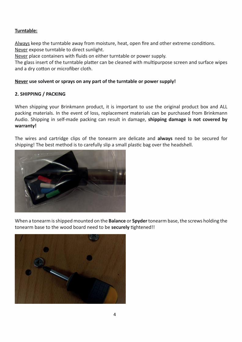
When a tonearm is shipped mounted on the Balance or Spyder tonearm base, the screws holding the tonearm base to the wood board need to be securely tightened!!
4

ALWAYS strap the tonearm tube to the arm rest when shipping a tonearm mounted on the arm board!! ALWAYS remove the counterweight prior to shipping!!
3. TOOLS
These items may be a part of the tool kit supplied with your Brinkmann product. Please note that not all tools are needed for all products: only the tools necessary for the purchased product are part of the included tool supply. All tools are metric.
Tool for azimuth zero adjustmentM6 allen key to clamp Balance tonearm baseM5 allen key to mount Spyder jigM3 allen key to clamp tonearm top plateM2.5 allen key to clamp tonearm socketM2 allen key M2 allen key (short) for azimuth adjustmentM1.5 allen key to clamp cueing device and counterweightSmall Screwdriver for speed adjustment
5

4. GENERAL INFORMATION FOR BRINKMANN TURNTABLES
Please follow the set up procedure in the precise order as described in this manual, e.g. always place the platter on the bearing before placing the motor next to the turntable to prevent acciden-tal damage to motor or platter. The tonearm adjustments in the manual follow the most sensible order to achieve good results and minimize potential damage without having to go back and forth between different adjustments.
Analog Setup
Although many turntable manufacturers, reviewers and audiophiles insist that complex, instrument-based setup is required for proper turntable function, Helmut Brinkmann has always believed that “Simpler is better;” for this reason, Brinkmann turntables have been engineered for simple and stable setup. When skilfully used, basic tools—protractor, stylus force gauge, etc.—and a critical ear are all that are required to obtain optimal results. This is actually an essential compo-nent of Brinkmann’s design process. USB microscopes, electronic azimuth meters and other complex apparatus are, in our opinion, not necessary to achieve superb performance from Brinkmann Analog Systems.
Placement
All Brinkmann turntables are non-suspended designs with a strong emphasis upon resonance control and discharge of unwanted mechanical energy. Consequently, the materials which comprise the stand or base upon which the turntable is placed have a significant influence upon sound quality. We have had the best results with aluminium and granite surfaces, as their microstructure is ideal to transfer resonances evenly across the entire resonant spectrum. As a general rule, harder materials like granite or aluminium are better suited for the placement of a Brinkmann turntable than softer materials like wood or plastic.Since tastes are different and sound is always a matter of synergy of the whole system, we encourage you to experiment with different materials.
Levelling Procedure
Level the stand, NOT the turntable: although the feet on Brinkmann turntables are adjustable, they are primarily designed for resonance control and rigidity. By design, our turntables are not as sensitive to level adjustments as other turntables. Due to the precision engineering and manufactu-ring of all Brinkmann turntables, the relative geometries of the various pieces will all be level in re-lation to each other: if the stand (Platform) upon which the turntable is placed is level, the turntable will be level.Start with the turntable feet screwed all the way into the base and then adjust/extend from the base until all three feet make contact with the Stand and the turntable doesn’t wobble. The goal is to have the feet as close to the turntable body as possible.
6

Spacer and Clamp
The Tool Kit for all Brinkmann turntables contains a small, black plastic ring which fits over the spindle and is the counterpart for the record clamp. It is easily removable and replaceable. The spacer slightly lifts the LP near the spindle. When the record clamp is placed over the spindle and screwed down, it presses the record downwards. This ensures an optimal contact between the LP and the crystal glass platter surface. Forceful use of the record clamp can damage or, at worst, strip the threads on clamp and/or spindle. Please proceed with care! With thick records, 180g and thicker, it’s better to remove the spacer to prevent damage to the thread of clamp and spindle!The round felt disc included in the tool set is intended for use as a “Place Mat” for the record clamp.
Glass Mat
The platter mat supplied with all Brinkmann turntables is made from crystal glass, cut to our precise specifications for optimised resonance control. Crystal also offers a surface that is easy to clean, thereby protecting records from dust and damage. Cutting and smoothing the rim of the crystal glass mat is a technically difficult process and can lead to small imperfections or slight unevenness of the rim. This has no impact on the superior sonic qualities of glass, it is merely a consequence of cutting and processing crystal.
Maintenance
Brinkmann turntables are largely fabricated of black anodized aluminium and when handled carefully the surface will retain a new and pristine appearance for many, many years. A dry microfi-ber cloth is the best and safest option to remove dust from all surfaces without damaging the finish. No alcohol or aggressive/abrasive cleaners should be used on any of the turntable surfaces! No solvents should be sprayed directly on the glass platter mat! A small amount of mild cleaner applied to a cloth, and not directly to turntable surfaces, may be used when absolutely necessary. Use of aggressive or otherwise non-approved cleaners can damage the finish and void the warranty!The platter bearing is sealed and maintenance-free, the oil doesn’t need to be changed or refilled.
Protective Red Tape On The Bearing
The red tape around the bearing of the Spyder, Oasis and Bardo is applied at the factory to prevent scratches during testing. It can either be removed or left on the bearing. The tape has no influence on the sound, nor does it interfere with proper turntable function.
7

5. GENERAL INFORMATION FOR BRINKMANN BELT DRIVE TURNTABLES
Brinkmann Sinus Motor
For over two decades Brinkman Turntables employed the highly-regarded German manufacturer Papst to supply Tape Capstan motors for use in our belt drive turntables. Techni-cally and musically we had good results with this motor in combination with our proprietary analog speed controller.Helmut Brinkmann’s extensive research and development program, which resulted in the development of our bespo-ke, direct drive motor for the Oasis and Bardo turntables gave him valuable insight into the control of magnetic fields and how to apply this knowledge to reduce cogging in a motor. The next logical step was to apply this knowledge to the design of a new motor for the belt drive turntables.Compared to the Papst, Brinkmann’s new Sinus motor is better suited to driving a high mass platter like the ones found in our Balance and Spyder turntables, because the use of 4-phase (4 times 90°) drive circuitry—as opposed to the commonly used two-phase design used by Pabst and others--enab-les a much smoother rotation with reduced “cogging.” The arrangement of the driving coils and the neodymium magnets in combination with the drive circuit achieves 12 “pulses” per revolution. Additionally the motor’s large rotating mass of 500 grams, achieved by using a nickel-plated steel motor body, works likes a flywheel, thereby enhancing speed stability, driving the platter of the turn-table with a very evenly distributed force and reduces vibration. The smooth and quiet rotation of our new, proprietary motor allows longer instrument sustains which results in more detail, resolution and musicality. The virtually frictionless progression of the motor is readily audible in the effortless flow of the music. Our Sinus motor also generates more torque and is therefore able to reduce start-up time to a few seconds, which makes it an ideal match with the new (and optional) RöNt II vacuum tube power supply, which also enhances Brinkmann direct drive motors.
Bearing Heating
As with all high performance bearings, the platter bearings of belt drive turntables are designed to operate at a specified, optimum temperature. Because the bearings in other ‘tables achieve their optimum temperature as a result of bearing friction (i.e., as the platter spins the bearing heats up), they must necessarily be designed with lower mechanical tolerances. Brinkmann belt drive turntables employ a bearing heater to maintain a stable temperature in the platter bearing. This enables Brinkmann’s platter bearings to be engineered and manufactured to much tighter toleran-ces than the bearings found in other turntables, as constant temperature of the platter bearing faci-litates the implementation of optimal, higher-precision tolerances. This ensures smoother platter ro-tation, extended bearing life, vanishingly low wow and flutter and guarantees optimal performance from the moment of turn-on.
8

Attributes and technical specifications Balance / Spyder Drive Mechanism: Belt drive using Sinus 4 -Phase, 12-Pole motorPower supply: External solid-state power supply is Standard Equipment. RöNt II External, vacuum-tube power supply is Optional.Bearing: Hydrostatic, zero-maintenance bearing with heating for optimal tolerancesPlatter: Resonance-optimized, anodized aluminum alloy; crystal-glass platter mat, aluminum clampChassis: Resonance-optimized, anodized aluminum alloyArm board: Movable (rotating) without play for simple and precise tonearm adjustment. Accepts all tonearms between 9” and 12“ effective length, as well as several linear tracking tonearmsConnectors: RCA, XLR or feed-through for tonearms with 5-pin DIN connectorsRPM: 33 1/3 and 45, selectable by a switchLED indicator for speed (33 1/3 = green, 45 = red) Deviation from nominal speed: 0.0% (adjustable) Fine adjustment of speed: ± 10% with trim potWow & Flutter: 0.07% linear, 0.035% weighted DIN 45507Speed-up time Balance: 8 / 12 seconds (33 1/3 / 45 rpm)Speed-up time Spyder: 6 / 8 seconds (33 1/3 / 45 rpm)Rumble (noise): -66 dB (test record DIN 45544); -70 dB (measuring adapter)Weight Balance: Total 33 kg (1-arm); 35 kg (2-arm), Chassis 9 kg (1-arm), 11 kg (2-arm), Platter 18 kg, Power Supply 3 kg; Motor 3 kgWeight Spyder: Total 21 kg (Bearing w/ 1 jig and tonearm 5 kg, Platter 10 kg, Power Supply 3 kg, Motor 3 kg)
9

6. SET UP OF BALANCE TURNTABLE
The Balance turntable is available in both 1-arm and 2-arm versions. Please note: because there are essential mechanical differences of the chassis and the motor, the 1-arm Balance can not be upgraded to the 2-arm version.
Tool Kit
M6 allen key to clamp Balance tonearm baseM3 allen key to clamp tonearm top plate and height adjustment of spikesSmall Screwdriver for speed adjustmentGround CordSpacerCircular Felt Mat for ClampBelt
Chassis
Place the chassis on a levelled surface. The platter and bearing should be in the centre of the base, with the tonearm base of a 1-arm Balance at the rear right side (TT viewed from front) or, in the case of the 2-arm version, with both tonearm bases to the rear. The Balance chassis features 3 adjustable spikes whose main purpose is for vibration control and discharge of unwanted resonances. The spikes should be adjusted to simply make contact with the stand surface, so that the chassis should not lift from the ground. (Levelling of the chassis is not critical but all spikes should be extended from chassis as little as possible, so as just to make contact with the surface of the shelf.)
10

Extending or withdrawing the spikes and the amount of contact that the chassis has to the surface upon which it is mounted will influence sound quality. Our recommendation might not be ideal for every system and requires experimentation. The 2-pole connector at the rear of the chassis is for the bearing heater. Please connect the cord of the power supply to the connector. The cap screw locks the connector and keeps it in place. Please remove the 2 cotton swabs in the bearing housing before placing the platter on the bearing!
Platter
The turntable platter is very heavy. It’s advisable to look through the hole for the spindle when carefully lowering the platter on the bearing to keep it centred. Attention! Please make sure that your hands don’t get caught between platter and chassis, especially when lowering the platter on the 2-arm Balance! Please place platter over bearing BEFORE positioning motor near the TT.Always carry platter and chassis separately.
Motor
The motor should be placed on the left side of the turntable (When viewed from the front.) The optimal distance between the platter rim and the centre of the motor pulley is 7,5cm. The belt connects the motor pulley with the platter and runs through the horizontal groove in the platter and the pulley. The motor needs to be placed correctly to make sure that the belt runs free through the cut out in the motor housing. The acrylic cover for the motor might have a protective tape that can be removed before placing the cover on the motor. The switch unit of the 2-arm Balance is permanently connected to the motor while the switch unit of the 1-arm Balance needs to be connected to the motor through a 5-pole socket in the connecting rod. The cap screw ensures a stable connection. Please remove the switch unit of the 1-arm Balance before lifting the motor to prevent damage to the connector!
The cable of the motor connects to the 3-pole socket in both the stan-dard solid-state power supply or the optional, RöNt II tubed power supply. The cap screw prevents unin-tended removal of the cord. There are 2 holes at the rear of the motor housing. They give access to the “trim pots” used for speed ad-justment. The screwdriver included in the tool kit fits the trim pots: turning
11

clockwise increases the speed, anti-clockwise decreases the speed. The left trim pot (viewed from the front of the turntable) is for the adjustment of 33 RPM and the right trim pot for 45 RPM. When viewed from the Speed Selector Switch, the trim pot for 33 RPM is on the same side as the 33 RPM button and the 45 RPM trim pot is on the same side as the 45 RPM button.
Power Supply
The casing of the power supply is crafted of aluminium. It is completely sealed and there are NO user-serviceable parts inside. Please make sure that the power supply is placed in an open shelf that allows air circulation.The AC power cord connects the power supply to the mains. A blue LED on the front panel lights up when the power supply is connected.
Tonearm base
The Balance tonearm base consists of a pod and a top plate. The pod fits in the hole of the plinth. It can be rotated 360° degrees to adjust the correct pivot-to-spindle distance for the tonearm and, when used with the Brinkmann Stylus Protractor, facilitates foolproof, highly accurate cartridge alignment.The 6mm key (with round, Black Plastic knob) in the tool kit can be used to tighten the large screw in the back of the chassis to clamp the tonearm base and hold it in place. The stainless steel ring of the tonearm base holds the gold socket for the ground connection and the RCA or XLR connectors (when equipped with a Standard top plate). There are 2 options for top plates: 1) Standard, to fit tonearms from 9” to 10.5” and 2) Extended, to fit tonearms from 10.5” to 12”. Both top plates can be mounted on the tonearm pod via 3 screws and are interchangeable. Brinkmann tonearm bases can be pre-drilled for almost all current tonearms.Before playing LPs: Please make sure to connect the ground cord (included) between the tonearm base and your phono preamplifier, with the banana plug end to the gold socket in the tonearm base and the spade end to the phono preamplifier.
12

7. SET UP OF SPYDER TURNTABLE
The Spyder turntable can be outfitted with 1 to 4 tonearms. Additional jigs with tonearm pods can be added, removed or exchanged any time. This arrangement allows a maximum of versatility and is one of the most significant design innovations of the Spyder. Unlike the Balance, which must be ordered as either a 1-arm or 2-arm turntable, any Spyder can accommodate up to four tonearms, the number of arms increasing or decreasing at the owner’s whim.
Tool Kit
M5 allen key to mount Spyder jigM3 allen key to clamp tonearm top plateSmall Screwdriver for speed adjustmentGround CordSpacerCircular Felt Mat for ClampBeltReplacement screw for jig
Bearing Housing
Place the Bearing Housing on a levelled surface. The platter and bearing should be in the centre of the base. The 2-pole connector at the rear of the Bearing Housing is for the bearing heater. Please connect the cord of the power supply to the connector. The cap screw locks the connector and keeps it in place. Please remove the 2 paper swabs in the bearing housing before placing the platter on the bearing!
13

Jigs with tonearm pods
The jig(s) mount in any desired position around the be-aring via 2 screws. The most convenient tonearm posi-tion for the user is the back right position and the back left position for the second tonearm. The 2 blue screws supplied by Brinkmann are actually sophisticated resonance-tuning devices optimized to complement the characteristics of the Spyder. We re-commend using these screws ONLY to mount the jig(s) and not exchange them with other screws.The contact between jig and tonearm base is pre-adjus-ted to ensure that the tonearm base is level and that it connects to the surface with all three spikes. In case one or more spikes don’t touch the surface, correct by loosening the two screws that can be found inside the tonearm base: they’re accessible when removing the top plate of the tonearm base. The screws should be tightened again as soon as the tonearm base is level. You will find it helpful to have the platter on the bearing for this adjustment.
Platter
It’s advisable to look through the hole for the spindle when carefully lowering the platter on the bearing to keep it centred. Please place platter over bearing BEFORE positioning motor near the TT.Always carry platter and chassis separately.
Motor
The motor can be placed in any free position around the turntable, the optimal distance between the platter rim and the centre of the motor pulley is 7,5cm.The belt connects the motor pulley with the platter and runs through the horizontal groove in the platter and the pulley. The cable of the motor connects to the 3-pole socket in both the standard solid-state power supply or the optional, RöNt II tubed power supply. The cap screw prevents unintended removal of the cord. The speed can be changed with the 2 speed switches located atop the motor housing. The LED lights up green for 33 and red for 45. When the LED lights up orange after initially connecting the motor, it can be switched off by pushing both switches in turn. This is not a defect. There are 2 holes on top of the motor housing, located next
14

to either speed switch. They give access to the trim pods for the speed adjustment. The screwdriver included in the tool kit fits the trim pots: turning clockwise increases the speed, anti-clockwise de-creases the speed.
Power Supply
The casing of the power supply is crafted of aluminium. It is completely sealed and there are NO user-serviceable parts inside. Please make sure that the power supply is placed in an open shelf that allows air circulation.The AC power cord connects the power supply to the mains. A blue LED on the front panel lights up when the power supply is connected.
Tonearm base
The Spyder tonearm base consists of a pod and a top plate. The top plate holds the locking collar for the tonearm and clamps via 3 screws. By loosening the screws, the top plate can be rotated 360° to adjust the correct pivot-to-spindle distance for the tonearm and, when used with the Brinkmann Stylus Protractor, facilitates foolproof, highly accurate cartridge alignment.The stainless steel ring at the bottom of the tonearm base holds the gold socket for the ground connection and the RCA or XLR connectors (when equipped with a Standard top plate). There are 2 options for top plates: 1) Standard, to fit tonearms from 9” to 10.5” and 2) Extended, to fit tonearms from 10.5” to 12”. Both top plates can be mounted on the tonearm pod via 3 screws and are interchangeable. Brinkmann tonearm bases can be pre-drilled for virtually all current tonearms.Before playing LPs: Please make sure to connect the ground cord (included) between the tonearm base and your phono preamplifier, with the banana plug end to the gold socket in the tonearm base and the spade end to the phono preamplifier.
15

8. GENERAL INFORMATION FOR BRINKMANN DIRECT DRIVE TURNTABLES
Magnetic drive
The Brinkmann magnetic direct drive motor was developed by Helmut Brinkmann and is produced in our factory in Germany. There is a single bearing for the motor and the platter. A circular magnet is mounted into the bearing of the platter and is concentrically driven into rotation via coils on the circuit board beneath the magnet. An electronic circuit drives the coils via two magnetically sensitive resistors that react to the magnetic fields, enabling a highly constant and slow circular movement.
Historically, direct drive systems have a dubious reputation among audiophiles. This is because older direct drive turntables were constructed for studios and radio stations where it was necessary to have very quick start-up times of less than a second, which was achieved with high torque motors and “Stiff” speed control that speed-up and stop the motor very rapidly. These motors were subject to heavy cogging effects accompanied by high instantaneous wow & flutter specifications. To avoid this, we devoted great effort to developing a proprietary motor con-trol that transfers just enough energy to the motor to enable it to remain at constant speed. In conjunc-tion with the 22-pound platter used for Bardo and Oasis models, the Brinkmann’s proprietary motor and control board result in less cogging and noise, lower wow and flutter and a smoother, richer, more musically involving sound. The motor’s stator consists
of four specially designed field coils, which are mounted concentrically with high precision around the platter bearing. Based on listening sessions we decided to forgo the typical 90-degree mounting angle in favor of a non-standard 22.5-degree roster, which, due to the magnetic fields overlapping, further reduced cogging. The motor’s rotor also acts as the sub-platter and carries a magnetic ring with eight poles on its underside. Inside the motor, the rpm of a speedometer disc is measured and turned into variable voltage that is fed into a control circuit where the rpm is compared to the reference voltage that is adjustable via the trim pots. A separate heater for the bearing, as inclu-ded with the Spyder and Balance bearings, is not necessary as the motor circuit is supplied current continuously, regardless of whether the speed is switched to zero or 33-rpm or 45-rpm. In this way, the bearing is kept warm by the quiescent current of the motor drive. For those who are interested, there is more information about the magnetic direct drive motor of our turntables Oasis and Bardo on our website: www.brinkmann-audio.com in a white paper about the Oasis.
The platter of the direct drive turntables can be stopped by hand to change LPs without any ne-gative effect for the motor!
16

Attributes and technical specifications Oasis / Bardo Drive Mechanism: Direct Drive, Platter driven by a proprietary, magnetic field motorPower supply: External, solid-state power supply is Standard Equipment. RöNt II External, vacuum-tube power supply is OptionalBearing: Hydrostatic, zero-maintenance bearing Platter: Resonance-optimized, anodized aluminum alloy; crystal-glass platter mat / clampPlinth Oasis: Resonance-optimized anodized aluminum alloy, wood frameChassis Bardo: Resonance-optimized anodized aluminum alloyArm board Oasis: Movable (rotating) without play for simple and precise tonearm adjustment. Ac-cepts all tonearms between 9” and 10.5“ effective lengthArm board Bardo: Movable (rotating) without play for simple and precise tonearm adjustment. Ac-cepts all tonearms between 9” and 12“ effective length, as well as several linear tracking tonearmsConnectors: RCA, XLR or feed-through for tonearms with 5-pin DIN connectorsRPM: 33 1/3 and 45, selectable by a switchLED indicator for speed (33 1/3 = green, 45 = red) Deviation from nominal speed: 0.0% (adjustable) Fine adjustment of speed: ± 10% with trim potWow & Flutter: 0.07% linear, 0.035% weighted DIN 45507Speed-up time: 12 / 16 seconds (33 1/3 / 45 rpm)Rumble (noise): -64 dB (test record DIN 45544); -68 dB (measuring adapter)Weight Oasis: Total 26 kg (Plinth 15 kg, Platter 10 kg, Power Supply 1 kg)Weight Bardo: Total 20 kg (Chassis 9 kg, Platter 10 kg, Power Supply 1 kg)
17

9. SET UP OF OASIS TURNTABLE
The Oasis has a wood plinth. The standard wood finish is Makassar high gloss, other wood options might be available on request as are both matte or high gloss finishes. Due to the wood plinth, only tonearms from 9” to 10.5” can be mounted on the Oasis. (The Bardo, which is essentially a “Plinth-less” version of the Oasis, can accommodate arms of virtually any length.)
Tool Kit
M3 allen key to clamp tonearm top plate and height adjustment of Oasis feetSmall Screwdriver for speed adjustmentGround CordSpacerCircular Felt Mat for Clamp
Plinth / Motor
Place the plinth on a levelled surface. The plinth features 3 feet, whose main purpose is for resonance control and discharge of unwanted resonances. They can be accessed through the holes in the top plate.Attention! There are strong magnetic fields around the bearing, be careful never to bring metallic objects near the turntable without platter in place.Please remove the 2 paper swabs in the bearing before placing the platter on the bearing!The cable of the standard, solid-state power supply or the optional RöNt II tubed power supply connects to the 3-pole socket at the rear of the plinth to supply the motor. The cap screw prevents unintended removal of the cord. The speed can be changed with the 2 speed switches on the left side of the plinth. The LED lights up green for 33 and red for 45. When the LED lights up orange after initially connecting the motor, it can be switched off by pushing both switches sequentially. This is not a defect.
18

There are 2 holes located next to either speed switch. They give access to the trim pods for the speed adjustment. The screwdriver included in the tool kit fits the trim pots: turning clockwise increases the speed, anti-clockwise decreases the speed. The plinth holds the gold socket for the ground connection and the RCA or XLR connectors. Before playing LPs: Please make sure to connect the ground cord (included) between the tonearm base and your phono preamplifier, with the banana plug end to the gold socket in the tonearm base and the spade end to the phono preamplifier.
Platter
It’s advisable to look through the hole for the spindle when carefully lowering the platter on the bearing to keep it centred. Attention, please hold the platter by the outer rim to make sure that your hands don’t get caught between platter and plinth. Always carry platter and plinth separately.
Power Supply
The casing of the power supply is crafted of aluminium. It is completely sealed and there are NO user-serviceable parts inside. Please make sure that the power supply is placed in an open shelf that allows air circulation.The AC power cord connects the power supply to the mains. A blue LED on the front panel lights up when the power supply is connected.
Tonearm base
The top plate holds the locking collar for the tonearm and clamps via 3 screws. By loosening the screws, the top plate can be rotated 360° to adjust the correct pivot to spindle distance for the tonearm and, when used with the Brinkmann Stylus Protractor, facilitates foolproof, highly accurate cartridge alignment. The top plates fit tonearms from 9” to 10.5” they can be mounted via 3 screws and are exchangeable. Brinkmann tonearm bases can be drilled for virtually all current tonearms.
19

10. SET UP OF BARDO TURNTABLE
The Bardo combines the direct drive technology of the Oasis with the classic Brinkmann “Plinthless” chassis structure pioneered in the Balance. Bardo can mount tonearms from 9” to 12”.
Tool Kit
M3 allen key to clamp tonearm top plate and height adjustment of Bardo footSmall Screwdriver for speed adjustmentGround CordSpacerCircular Felt Mat for Clamp
Chassis / Motor
Place the chassis on a levelled surface. The chassis features 3 feet whose main purpose is for resonance control and discharge of unwanted resonances. The foot next to the tonearm base can be accessed through a hole in the chassis, the other 2 feet can be moved up and down by turning the feet.Attention! There are strong magnetic fields around the bearing, be careful never to bring metallic objects near the turntable without platter in place.Please remove the 2 paper swabs in the bearing before placing the platter on the bearing!The cable of the standard, solid-state power supply or the optional RöNt II tubed power supply connects to the 3-pole socket at the rear of the chassis to supply the motor. The cap screw prevents unintended removal of the cord.
20

The speed can be changed with the toggle switch on the front of the chassis, below the tonearm base. The LED lights up green when moved upwards for 33 and red when moved downwards for 45. The middle position stops the motor. There are 2 holes located next to either speed switch location. They give access to the trim pods for the speed adjustment. The screwdriver included in the tool kit fits the trim pots: turning clockwise increases the speed, anti-clockwise decreases the speed.The chassis holds the gold socket for the ground connection and the RCA or XLR connectors. Before playing LPs: Please make sure to connect the ground cord (included) between the tonearm base and your phono preamplifier, with the banana plug end to the gold socket in the back of the chassis and the spade end to the phono preamplifier.
Platter
It’s advisable to look through the hole for the spindle when carefully lowering the platter on the bearing to keep it centred. Always carry platter and chassis separately.
Power Supply
The casing of the power supply consists of aluminium. It is completely sealed and there are NO user-serviceable parts inside. Please make sure that the power supply is placed in an open shelf that allows air circulation.The power cord connects the power supply to the mains.
Tonearm base
The top plate holds the locking collar for the tonearm and clamps via 3 screws. By loosening the screws, the top plate can be rotated 360° to adjust the correct pivot to spindle distance for the tonearm and, when used with the Brinkmann Stylus Protractor, facilitates foolproof, highly accurate cartridge alignment.There are 2 options for top plates: 1) Standard, to fit tonearms from 9” to 10.5” and 2) Extended, to fit tonearms from 10.5” to 12”. Both top plates can be mounted on the tonearm pod via 3 screws and are interchangeable. Brinkmann tonearm bases can be pre-drilled for almost all current tonearms.
21

11. RöNt II TUBED POWER SUPPLY
The optional RöNt II tube power supply is especially made for the direct drive motors of the Oasis and Bardo—as well as the new Sinus motors of the Balance and Spyder—and fits their demands of start-up, drive and stand-by current consumption perfectly. It delivers a stabilized output voltage of 24VDC; the output is short circuit proof. The output voltage ramps down when the current exceeds 500mA, which is more than the motors need during start up. Once the platters reach proper speed the current draw is much less, as it is during stand-by. The tube supply utilizes two high current low resistance tetrodes (PL36) and a full wave rectifier (5AR4). All tubes are made for long life; the tetrodes are good for 10000 hours under full load (which is by far not needed here). Secondary AC voltage is rectified by the full wave rectifier and directly fed to the current tetrodes. A filter network of capacitors and a choke feed a clean voltage of about 180VDC to the regulating tetrodes. The output voltage of 24VDC is controlled by referencing to a temperature-stabilized voltage reference. For start-up, the motor of the turntable needs about 450mA for the first brief moment, then the current drops to about 80mA. You may reduce the start-up current draw by giving the platter a push. (As the Direct Drive motor used in both Bardo and Oasis was purpose-designed for slow and gentle start-up, giving the platter a light push will expedite start-up.)When switched to stop, the supply reduces the output current to about 60mA, just enough to hold the motor electronics under current for the next start. The tube supply may remain in this stand-by state (motor „stop“) for a long time, but to increase the tubes life, please switch off the mains switch when the supply is not used for some time like overnight. Furthermore, as the RöNt II can become quite warm during normal operation, it is advisable to place the unit on a surface (stone or metallic) that will not be affected by heat.
The motor is connected to the 3-pole connector at the rear panel; there is a special cord in the supply to connect the direct drive turntables.
The heat of the big (5AR4) tubes may exceed 120°C, please do not touch the tubes during operation. The tube supply should have its solid granite support underneath, as the heat of the tubes could cause some discoloration in the finish of fine furniture.
Attributes and technical specifications
Power consumption: approximatley 80 Watts Output voltage: stabilized to 24VDC Output current: 0-500mA peakTube life time: better than 10,000 hoursTubes: 2x PL36, 1x 5AR4Dimensions: 180x310x100mm, 12kg
22

12. GENERAL INFORMATION FOR BRINKMANN TONEARMS
1-tonearm mount2-mounting socket3-clamp screw for mounting socket, allows VTA adjustment and turning the tonearm (adjusting the distance between tonearm tube and turntable platter in resting position) 4-tonearm tube5-clamp screw for cueing unit height adjustment6-height adjustment screw for VTA adjustment7-headshell8-azimuth adjustment screw9-counterweight10-magnet screw to adjust anti-skating force11-anti-skating magnet (not adjustable)12-ring magnet for anti-skating13-DIN socket (optional)14-screw for mounting the DIN-socket, when removing both screws, the DIN socket can be rotated 180°, use great care!15-clip to hold the tonearm tube in resting position16-hex screw to fixate the cueing device
23
7
1
92
12
10
6
5
38
11
14
13
4
15
15
16

Brinkmann tonearms have a strong focus on resonance control to prevent unwanted vibrations from degrading the music signal. The principal material is anodized aluminium. Brinkmann arm tubes have a special, hard-anodized ceramic surface to optimize the discharge of tonearm resonances. All tonearm bearings are the highest quality, Swiss-made ball bearings which enable a play-free adjustment with maximum stability. All tonearm bearings are adjusted for optimal sonic results at Brinkmann Audio and secured by a cap screw to ensure a long-term adjustment stability. It is neither advisable nor necessary to adjust the bearings or cap screws! The 12.1 and 10.5 tonearms are gimbal bearing designs and the 10.0 is a unique hybrid “gimbaled unipivot” exclusive to Brinkmann.
Please follow the set up procedure in the same order as described in the manual, the tonearm ad-justments follow the most sensible order to achieve good results and minimize potential damage without having to go back and forth between different adjustments.
Tool Kit
Tool for azimuth zero adjustmentM2.5 allen key to clamp tonearm socketM2 allen key M2 allen key (short) for azimuth adjustmentM1.5 allen key to clamp cueing device and counterweightSmall Screwdriver for speed adjustmentScrews and copper washers for mounting collarScrews and washers for mounting the cartridge
10.0 Tonearm Bearings
The Brinkmann 10.0 tonearm offers unique advantages in construction details, which elevate it above competitive tonearms, both sonically and in aesthetic terms. Special attention was given to the construction of the bearings and their alignment. Experiences with different tonearms and their bearing designs have led us to the develop something special which incorporates the best of different technologies.Usually tonearms are either single (“Uni”) pivoted or gimbal pivoted.A gimbal bearing construction, as you find it in our tonearms 10.5 and 12.1, is a very resonance-proof construction. Usually done with roller bearings, the friction, which opposes a free motion, depends primarily on the quality and alignment of the bearings used. Of course, in our tonearms we use the finest Swiss-made precision bearings available. To keep friction as low as possible, these bearings are very small, keeping the ground on which the balls run close to a fraction of a millimetre. In this way, these bearings come close to the ideal of a single pivot point. Real single pivots are usually made of a spike, rotating in a kind of socket, which keeps the spike centered in the pivot. This construction should reduce friction even more, but that would mean the point at which spike and socket meet is reduced to almost zero surface area. As this is impos-sible to achieve in reality, the actual friction is often larger than with most “Uni-Pivot” arms than those employing small, precision bearings. The two pieces of this bearing do not roll on each other,
24

but drag instead. This can cause wear that increases over time; as a result, the lifetime of such a construction is limited and sensitive to mishandling. The peak of the spike would flatten during time. Single pivot bearing construction is used quite often, as there is only one single bearing without the necessity of alignment and it’s easy to manufacture. To keep this single bearing quite resonant free, the whole arm construction is usually heavy and the use of damping oil is recommended. The advantages, therefore, tend to be less expensive construction and less precise tolerances, advantages which are offset by shortened lifespan and compromised performance.Coming back to the Brinkmann tonearm 10.0, we use a new and proprietary construction that is intended to combine the advantages of a single-point “Unipivot” bearing with the steadiness and rigidity of the gimbal bearing. Two of our Swiss made small, high-precision roller bearings are responsible for the vertical movement up and down, as is usual in gimbal bearing construction. These two bearings at the sides of the vertical cylinder at the pivot housing are critically aligned to simultaneously minimize friction and “play.” The horizontal bearing construction is an advancement of the Unipivot concept: the complete arm rests on one of our small roller bearings at the top of the Bearing Housing. It meets a shaft that goes through the complete arm down to the arm shank at the bottom. As the mass of the arm rests on this bearing, there is no alignment necessary. In some way, the arm “hangs” with its mass resting upon this bearing. The mass’ maximum point is well below this bearing, meaning that the center of gravity is below the pivot point. To keep friction as low as possible, this bearing is very small, keeping the ground on which the balls run close to a fraction of a millimetre. In this way, this bearing comes close to the theoretical ideal of a Unipivot, but without the wear caused by dragging a spike in a socket. In a typical Unipivot construction, this single bearing point allows simultaneously for horizontal and vertical movements of the arm. This causes some instability in form of staggering during tracking, which leads to permanently changing geometrical deviations. To prevent these deviations, we stabilize the arm with a second, freely running bearing at the bottom of the “spike”. A small amount of “Play” is engineered into this bearing to eliminate the influence of friction upon the top bearing.You can consider our construction as “Unipivot +2” or as “Gimbal pivoted -1” or simply a “Unipivot” depending on your preference; all that matters is that our design yields superior performance.
Drilling Data
All Brinkmann tonearms have the same mounting socket (base). Measure the correct Pivot to Spindle distance: 12.1 : 292 mm / 10.5 : 244 mm / 10.0 : 243 mm +/-2 mm
The Pivot to Spindle distance is of secondary importance as long as the final adjustment is geometrically correct. This is important to keep in mind because the distance between mounting holes and stylus can vary with different cartridges and it can get difficult to adjust the geometry correctly with some cartridges. A lot of modern turntables avoid this problem by offering a movable tonearm base with adjustable Pivot to Spindle distance.
25

Use compasses to lightly draw two circles around this point, one with a diameter of 20 mm and another with a diameter of 25 mm. Mark three points on the outer circle equidistant to each other at 120° angles as shown. Drill out the 20 mm circle using a woodcutting bit. Bevel the upper edge of the drilled hole slightly towards the center so that the top plate of the mounting assembly with its rounded seam at the mounting sleeve underneath will fit flush on the tone arm board. Next drill out the three marked points on the outer circle for M3 size machine screws. Insert the mounting assembly into the 20 mm diameter hole making sure that the setscrew for fixing the tone arm in the mounting sleeve is easily accessible. The slotted mounting plate and sleeve act like a clamp when the setscrew is tightened. To clamp the sleeve it is necessary that the two M3 mounting screws to the left and right of the slot allow some movement. They are therefore supplied with copper washers and must not be fixed too tightly. The third mounting screw opposite the slot is tightened without a washer.Insert the tonearm into the mounting sleeve. With the tonearm sitting firmly in the tonearm rest align it perpendicu-lar to the front of the turntable. As long as the setscrew in the
mounting plate has not been tightened the arm shaft in the sleeve can be moved up and down using the height adjustment screw.
Wiring
The tonearms can be ordered with a 5-pole socket. Otherwise the internal wires from the tone arm must be connected to a pair of either RCA or XLR terminals with the following color-coding:Red = right channel positiveGreen = right channel negativeWhite = left channel positiveBlue = left channel negativeThe copper-colored fifth (Litz) wire is for grounding the arm. It is connected to the tone arm base and the ground lead to the preamp.
26

13. SET UP OF BRINKMANN TONEARMS 10.0 / 10.5 / 12.1
Mounting the Cartridge
Please also refer to the section about cartridge mounting in FAQ Turntable Set Up.Mount the cartridge into the headshell with the mounting screws sitting approximately at the mid point of the slotted mounting holes in the headshell. Make sure that the sides of cartridge and headshell run parallel to each other. Keep the tonearm tube secured to the tonearm rest with the plastic clip while mounting the cartridge and counterweight! This prevents uncontrolled movement and potential damage to the cartridge. Release carefully while holding the tube. When the counterweight isn’t moun-ted or it’s too far in towards the back, the tonearm can flip upwards. The tonearm can be moved around without changing the alignment when the screw in the mounting socket is loosened, the tonearm tube should have a distance to the platter of approx.. 3cm where it’s closest to the platter to allow optimal anti-skating.
Mounting the counterweight
The first adjustment should be the tracking force following the manufacturer’s recommendation for the cartridge of your choice.The 10.5 and 12.1 counterweights consist of a centerpiece that holds two smaller, ring-shaped weights in the case of the 10.5 and one larger ring-shaped weight in the case of the 12.1. These auxiliary weights are held firmly in place by set screws. These are optimized for the tracking force needed for most cartridges, but since the centerpiece is the same, it’s possible to use the smaller rings for mounting very light cartridges on the 12.1 and the bigger ring to mount heavier cartridges on the 10.5.
The 10.0 has a one-piece counterweight. All counterweights have a Teflon insert to ensure easy movement on the arm tube and enhance the cancellation of resonances.With its beveled side pointing forward, i.e., towards the pivot, slide the counter weight onto the rear of the tone arm. The tracking force of the stylus can be adjusted by simply moving the counter weight back or forth. The position of the counter weight can be fixed with a small setscrew in the base weight. (Only the set screw closest to the bearing needs to be adjusted in order to loosen or tighten the counterweight.) Please be careful when tightening the set screw to avoid denting the tonearm tube.
27

Azimuth
To adjust azimuth take a strong magnifying glass (at least 10X) and look at the stylus exactly from the front. The triangle of the diamond stylus tip should point straight down. The best way to see this would be to lower the cartridge on a mirror and look from the front if the stylus and its mirror image are in one line.If a correction is necessary, loosen the screw at the underside of the headshell and carefully rotate the headshell until you have achieved the correct adjustment. The Azimuth Set Screw should be tightened again after the correction to avoid movement and minimize resonance. Please use the Tool for azimuth zero-adjustment (Supplied with your Brinkmann tonearm) before mounting a new cartridge. Mount the tool in the headshell with the two screws provided and lower the tonearm over the platter. When looking at the front of the tool, it should be level on the platter surface. If there is a gap on one side, loosen the screw on the underside of the headshell to turn it until it’s level, tighten the screw and check again. Only Brinkmann tonearms sold within the past several years allow azimuth adjustment. (Please consult your dealer or Brinkmann Audio.)
Cartridge Alignment
All Brinkmann turntables allow adjustment the of Pivot to Spindle distance by rotating the tonearm base after loosening the three screws on top of the tonearm base, or in the case of the Balance the clamp screw in the back of the chassis. This allows maximum adjustability for every tonearm and cartridge combination. Most alignment tools work with a specific Pivot to Spindle distance and then set the overhang to adjust the correct geometry. Using one of these tools, adjust the correct Pivot to Spindle distance and follow the instructions of your alignment tool. The Pivot to Spindle distance is of secondary importance as long as the final adjustment is geome-trically correct. This is important to keep in mind because the distance between mounting holes and stylus can vary with different cartridges and it can be difficult to adjust the geometry correctly with some cartridges. A lot of modern turntables avoid this problem by offering a movable tone-arm base with adjustable Pivot to Spindle distance.The Dennesen Geometric Soundtractor and Brinkmann Protractor work with a more simple and flexible method that can be used with a wide variety of tonearm and cartridge combinations. Please read the Protractor section of this manual for more information about cartridge alignment using the Brinkmann Protractor.
If you don’t have a Protractor or alignment tool or you don’t achieve the desired results with it, you might find the explanations of HTA in the Cartridge section of this manual helpful.
28

VTA
Now adjust the vertical tracking angle (VTA). It’s usually best to start with the tonearm tube parallel to the LP when the tonearm is lowered onto the record surface. (Proper Stylus force must be applied before obtaining parallel adjustment.) This usually is close to proper VTA and provides a good reference point. If you determine that after the correct setting of the geometry and HTA highs are too dull and bass is too plump and uncontrolled the VTA must be increased and the tonearm raised in the mounting socket. If the sound becomes hard, bright and glassy, you’ve raised the arm too much. At the correct setting highs sound
natural and transparent and bass lines sound bouncy and sonorous. To change the VTA, loosen the screw in the mounting socket of the tonearm, now the height can be changed with the height adjustment screw. Turn clockwise to raise the back of the tonearm (at the pivot) and counter clockwise to lower it. You might be needed to push the tonearm down gently when lowering the VTA. Exercise extreme caution! When the screw in the mounting socket is loosened, the tonearm can move and swing round. Cartridge damage can result.
Antiskating
The antiskating force is applied magnetically with a magnetic ring. It is magnetized at a 120° angle and it is set with an adjustable pin magnet in the back of the tonearm. The magnets try to move the tonearm back into its resting position and thus creating a counter force compensating the skating force. Screwing the pin magnet in the back further in increases the an-tiskating force. To find the correct setting it is best to use a recording with a voice centered between the speakers. Adjust the antiskating until you can hear the voice in the middle, between the speakers. Antiskating adjustments only make sense after azimuth, HTA and VTA have been set correctly. If the desired antiskating force exceeds the maximum magnetic force it is likely that one or more of the other settings are incorrect. Please note that setting the antiskating force could also slightly change the HTA.
To underscore this point again: Any adjustments which change the basic geometric setting that was determined by using a template or Protractor should be done with great care and in very small increments. Otherwise it is easy to lose track and move further and further away from the desired results.
29

Cueing
The tonearm cueing mechanism of the 10.5 and 12.1 can be height-adjusted by loosening the screw at the back of the plate that holds the cueing device and raising or lowering it. The cueing of our tonearms uses a thick lubricant for smooth and slow movement. In case the tonearm doesn’t move or goes down very slowly after lowering the cueing, move it back to resting position (away from the platter) and raise and lower the cueing a few times while gently pushing the cueing down to spread the lubricant in the inside. This might be necessary after exposure to cold or when not used for some time.
When the cartridge slides inwards when lowered on the LP instead of hitting the groove, then cleaning the rubber in the tonearm rest of the cueing with alcohol might help. The rubber holds the tonearm stable while being lowered and might fail when it’s greasy.
Attributes and technical specifications 10.0 / 10.5 / 12.1
Pivot to Spindle distance: 243 mm / 244 mm / 292 mm +/-2 mmEffective length: 258,8 / 259,8 mm / 305,6 mmOverhang: 15,8 mm / 15,8 mm / 13,6 mmDynamic mass: 14 g / 12 g / 14 gCartridge mount: ½” connector, long holesMinimum distance between mounting surface and platter top: 25 mmMounting depth: 30 mm / 46,5 mm with DIN socketCartridge weight: min 4 g, max 16 g with standard counterweightWeight: 410 g / 300 g / 350 gCounterweight: 150 g / 180 g / 200 g
30

14. GENERAL INFORMATION ON BRINKMANN CARTRIDGES
Brinkmann offers two different cartridges, the EMT-ti and the Pi. Both cartridges incorporate Brinkmann “fine-tuning” in several different areas and employing different materials like copper, titanium and various aluminum alloys. Special attention has been paid to optimizing unit-to-unit consistency and resonance tuning.
The Pi cartridge features a Micro Ridge stylus which offers the best resolution of the finest recorded details and which guaran-tees the best reliability. Natural-sounding in the midrange with good flexibility dynamics, it generates an enormous sounds-tage and three-dimensional images at the highest level of top cartridges. The stylus is mounted on a boron cantilever and drives a copper voice coil. Particular attention was paid to the rigidity of the magnetic circuit in order to prevent eddy currents.
The EMT-ti cartridge is essentially an EMT, which then under-goes heavy modifications. The list of modifications includes a van den Hul stylus, an aluminum mount with a resonance optimized contact patch (made of several layers of copper, titanium, beryllium and other special materials) and lastly our special sound-optimized micro-screws.
14. SET UP OF BRINKMANN CARTRIDGES
Both cartridges should be mounted using the aluminium screws with the titanium washers provided by Brinkmann. These screws together with the special damping materials between cart-ridge body and the mounting shell containing the connectors have been critically and sonically reso-nance-tuned, along with the internal wiring of the cartridge, to create a unique musical instrument.
Azimuth
To adjust azimuth, take a strong magnifying glass (at least 10X) and look at the stylus tip exactly from the front. The triangular front of the diamond stylus tip should point straight down. The best way to see this would be to lower the cartridge on a mirror and look from the front if the stylus and its mirror image are in one line.
Loading
We recommend 600 Ohm Loading for both cartridges, BUT different systems might sound better with different loading. We strongly recommend experimenting with different settings and choosing the one that sounds best. Resistive loading for MC cartridges are given strictly as a guideline and different systems might require very different settings.
31

HTA
We strongly recommend using an alignment tool, the Brinkmann Protractor or one of the other available alignment tools. This section only offers rough guidelines when there is no tool available. The horizontal tracking angle is the same as the geometrical alignment with a good alignment tool. The purpose is to achieve an optimal arc while the tonearm and cartridge move over the LP and to minimize the tracking error as it arcs across the record. Should there be no alignment tool available, the HTA setting can be improved by ear using the following methods:Loosen one of the two mounting screws on top of the head shell enough to turn the cartridge in minute increments inward or outward. To check the result you must re-tighten the screw every time. Check by playing a very familiar tune about one to two centimeters in from the beginning of the LP. Most revealing would be a solo voice recorded in the center of the stereo image. If the voice is slightly to the left of center the cartridge should be turned ever so slightly inwards towards the center spindle. The increments may be so slight that the naked eye could not detect any change. If the sound gets too soft and the image too hazy the cartridge as a whole should be moved slightly forward. Consequently, if the sound gets brittle it should be moved slightly back. These adjustments should be checked again after the cartridge is broken in. Please note that the setting for antiskate will also slightly influence HTA. Hence, changing the antiskating force amounts to a small adjustment in HTA.
Attributes and technical specifications EMT-ti / Pi
Type: Moving CoilWeight: approx. 11g / 14 gramsOutput voltage: 0,21 / 0.15mV (1cm / sec)Output impedance: 25 ohm / 20 ohmFrequency response: 20Hz ... 30kHzFrequency intermodulation: < 0.5%Vertical tracking angle: 23°Crosstalk: > 25dB (1kHz) Compliance: 15µm / mNStylus: vdHul, radius 3µm / micro ridge, radius 3µmTracking force: 1.8 – 2gRecommended load: 600 ohms
32

16. BRINKMANN PROTRACTOR FOR PRECISE ALIGNMENT OF TONEARMS AND CARTRIDGES
The Brinkmann protractor is machined with utmost possible precision. All machining steps of the ground plate and the guideway of the bar were performed in one set up on the CNC machine. This “Single Set-Up” process avoids any geometric errors caused by machine fixturesWe first mount the black block on the base plate and then the spindle hole is drilled, the guideway for the bar, the reticule and it’s grid of lines are machined. During this process only the tools of the CNC machine are changed but the protractor is not moved from the machine until all is done. This results in precision of better than 0.01 mm.With our construction methodology and tooling, the protractor allows for high-precision alignment of the cartridges and tone arm; however, very careful use of the protractor is still required to achieve optimal results. Geometrically, the protractor follows the IEC rules for the two null points—66.04 and 120.9mm—given as 66 and 121mm. There have been many discussions about different possible null points, but we will not debate this here. Evaluations have shown that the IEC rules are valid and lead to excellent sonic results. One special quality of this protractor is the offset between the guideway of the bar and the hole for the spindle. This offset is half of the difference between outer and inner null point 121 – 66mm. Due to mirroring over this offset the outer null point is automatically adjusted by adjusting the cartridge precisely on the inner null point; in other words, a single adjustment aligns both null points.
33

With this protractor there is no interpolati on necessary, which makes it quick and easy to achieve precise alignment of cartridges and tonearms. It should be recognized that a stylus contacti ng the record with only a few thousandths of a millimetre needs an extraordinary precise aligning: most protractors and alignment systems lack the necessary precision to obtain proper alignment. The protractor consists of the ground plate, bar and the protractor needle at the end of the bar.
Set up
The fi xing screws of the protractor should be loosened slightly at the beginning to allow a free movement of bar and the protractor needle. The protractor should be placed on the turntable spindle via the hole and the needle should be aligned to the pivot of the tonearm. In case the tonearm has no marked pivot point, blue tack or thick tape can help. Tape the top of the tonearm bearing structure, now draw lines across the top, use the middle where the lines cross as centre point for the protractor needle. This is NOT an issue with Brinkmann tonearms, which have a detente at the top of the pivot axis.The tonearm should be moved above the engraved grid and lowered gently with the stylus of the cartridge resti ng in the center-point of the grid. The side lines of the cartridge should be parallel to the lines of the grid. It might be necessary to move the cartridge in the tonearm headshell back or forth or even turn it a litt le to rotate the tonearm base and achieve the parallel alignment. In any event, the correct alignment is achieved when the stylus is in the centre of the reti cule and both sides of the cartridge are parallel with the grid marks.Now, ti ghten the fi xing screws at the bar to ensure that subsequent adjustments are accurate.
34

Critical Factors for Precise Alignment:It is essential to ensure that the deviation at the tonearm pivot (the protractor needle must be correctly placed in the middle) and the parallel alignment of the cartridge to the grid is as small as possible. The protractor needle should be fixed without play at the tonearm pivot to avoid deviation in the alignment. The fixing screws at the bar should be tightened carefully to achieve an accurate alignment. If the screws are too loose there will be too much play in the guideway of the bar and there will be some deviation in the alignment. If the screws are tightened too much, the plastic material of the guideway will bend and the alignment won’t be as precise. The fixture assembly is correct when the bar and protractor needle are tightened just enough to prevent movement. Sometimes, the correct alignment can be limited by the cartridge mounting slots in the tonearm headshell. In this case, the tonearm has to be moved to a different distance between spindle and pivot. It has to be moved so that the correct alignment of the cartridge can be achieved given the length of the headshell slots. Usually this is only possible by eccentrically drilled tonearm bases that can be turned. (As is the case with all Brinkmann turntables.) Or the arm itself has a slide which makes it possible for the arm to be moved with its mount (as with SME Arms). This sort of movement will alter the effective length of the tonearm, perhaps deviating from the given length mentioned in the data sheet of the arm. Such deviation is not a problem as long as the cartridge is properly aligned. As the bar of the protractor will follow this movement of the pivot (keep the protractor needle always on the pivot), and thus the reticule (Grid) will follow the new geometric situation the protractor will always show the correct aligning point of the cartridge. In this way it is very easy to find the correct arm mounting point and the correct cartridge mounting point in the tonearm. It may be the case that the cartridge has to be mounted at a slightly different angle than the headshell allows. This is OK as long as the cartridge mounting corresponds to the grid lines on the protractor.
Some Protractor Handling Tips
> First, loosen all fixing screws to enable the bar and the protractor needle to have free movement before placing the protractor on the platter. Be sure that the ground plate of the protractor is flat on the platter and the protractor needle is firm on the pivot without play. Then tighten the fixing screws again.
> Be sure that the protractor has no play (or at least as little as possible) by trying to move the ground plate a little.
> When you need to alter the distance between pivot and spindle by turning the arm base, first loosen the fixing screws of the bar a little. Don’t forget to fix them again when you align your cartridge.
> It is recommended to have the azimuth checked and corrected before aligning your cartridge with the protractor.
35

> The length of the cantilever will be effectively increased by the tracking force when you lower the cartridge on the centre point of the reticule. So it will help when you align your cartridge a little behind this point. The stylus should slip into the small drilling in the centre of the reticule ONLY when the full tracking force is reached. Therefore adjust the tracking force before aligning or use iterative process if necessary to make sure alignment is correct when proper cartridge tracking force is applied.
> Some cartridges do not have parallel sides and it is not easy to see if they are correctly aligned to the grid lines of the protractor. Perhaps a “Helping line” (a needle fabricated from antimagnetic material, for example) attached to the cartridge will do a good job.
> Sometimes the cantilever is not parallel to the sides of the cartridge body. In this case, you can simplify alignmednt by adjusting the cantilever parallel to the grid centre line behind the small drill-hole for the stylus.
> If it is necessary to mount the cartridge at an offset angle to the headshell slots, be sure that the stylus will always be kept on the small drilling in the centre of the reticule.
> When checking the sound quality of your alignment, always tighten the headshell screws to the same torque. If the screws do not have same torque it can show up as sonic differences which is not related to your alignment.
> Be sure to have the tonearm moved clear of the protractor before you remove the protractor from the platter; otherwise, stylus damage can occur.
36

17. FAQ TURNTABLE SET UP
Where can I best place my TT?
The material of the surface that holds the turntable has a significant influence on the sound. Differences in materials and levelling are more evident in modern, unsuspended TTs than suspended systems. The tracking process corresponds with resonances that travel through the TT, softer mate-rials absorb some of the resonances, but typically the absorption will occur at certain parts of the frequency spectrum and therefore cause a coloration of the sound. Harder materials transmit much better, but some materials, especially harder metals, tend to ring. Especially in unsuspended turn-tables, the base should be regarded as part of the turntable with the same significance regarding the choice of materials. Aluminium, granite, slate and some harder woods are popular materials because they’re fairly neutral. Since every music system is different, these are only recommenda-tions and the final choice of the turntable base should always be made with an eye—and ear—towards the synergy of the system. Harder and especially heavier materials give more stability and help with feedback problems that can occur through the floor or through the air. Lighter turntables are more sensitive to feedback than heavier designs and a massive, solid stand or platform is helpful. In some cases the turntable needs a decoupled isolation base or a damping system under the platform to prevent footfall problems.
What alignment tools are available and what’s the difference between them?
When a tonearm traverses the LP from the outer groove to the inner groove, it moves in a curve, not in a straight line. Consequently the cartridge and therefore the needle don’t maintain a constant angle in relation to the LP groove at all times. When the cartridge crosses the ideal line during the movement over the LP, it’s in a right angle (i.e., “Tangent”) to the groove. This is called ‘Null Point.” At all other positions, there’s a slight deviation from Tangency which is also called tracking error. Longer tonearms track with less tracking error and the offset angle in the headshell is smaller than in shorter tonearms. Geometric alignment is necessary to keep the tracking error as small as possible. Alignment tools can be based on different mathematical curves, i.e. Baerwald, Löfgren, IEC…..
Most commonly available alignment tools are based on one of two different systems:
One type works with the P/S (Pivot-to-Stylus) distance and overhang, first the P/S distance is adjusted according to the tonearm instructions and then the overhang is being set by moving the cartridge in the tonearm headshell. This type of alignment tool is based on a fixed P/S distance which is the case when the tonearm base or tonearm can’t be moved and the P/S distance can’t be changed. The second type of alignment tools is based on the Dennesen design (perfected by Brinkmann). Most modern turntables have a tonearm base that allows the adjustment of the P/S distance and there-fore gives a lot more adjustment flexibility. This type of alignment tool works without a specific P/S distance, so the geometry can be adjusted by changing the P/S distance or by moving the cartridge in the headshell. Either method allows the user to achieve correct geometry and this adjustment is more flexible when the slots in the headshell are limited and the cartridge can‘t be moved much.
37

What’s the best way to mount a cartridge?
Mounting or dismounting a cartridge is a moment that a lot of people fear because a small wrong movement can cause a lot of damage either to the cartridge or the fragile wiring. Here are a few things that make the job safer and easier:
-Place the turntable placed at a good height with free access to the tonearm.
-Have all tools available and some space to lean on your arms in order to steady your hands!
-Make sure there is ample light to accomplish proper setup and alignment.
-Put the mounting screws in the headshell holes first, before introducing the cartridge.
-Now. move the cartridge to the headshell and slip the con-nectors over the pins. Pliers help to hold the connectors, but make sure to use pliers carefully!
-Finally, use the screwdriver and fasten the screws to the cartridge
DONE!
-When dismounting the cartridge, start with the screws, not the connectors!
-Loosen the screws in the headshell and carefully move the cartridge away from the headshell improve access to the connectors
-Use the screwdriver like a crowbar and SLOWLY, CAREFULLY slip the connectors off the pins
38

What do I need to adjust apart from geometry and how does it work?
The following adjustments are important to achieve the best possible sonic result with your tonearm/cartridge combination. There are no practical instructions for the adjustments because these vary between tonearms from different brands.
-VTA (Vertical Tracking Angle) and SRA (Stylus Rake Angle) describe the vertical angle of the stylus in the groove, looked at from the side of the cartridge. Ideally this should be 90° to 93°. A good way to start is to set the tonearm tube parallel to the platter when the cartridge is in the groove. A small spirit level or a ruler can help to achieve this. Assuming that the stylus and cantilever are mounted correctly in the cartridge, this should get you close to the ideal angle. Finer adjustments can be done by ear or with the help of a microscope that magnifies the stylus.
-The Azimuth is the vertical angle of the stylus in the groove, viewed from the front of the cartridge. Azimuth adjustment ensures that the cartridge tracks both sides of the groove evenly. The best way to see this would be to lower the cartridge on a mirror and look from the front if the stylus and its mirror image are in one line. Another popular way to check the Azimuth is the Fozgometer. It’s used with a test LP that has signal on only one channel at a time. If it measures cross-talk, which descibes the information from one channel that bleeds into the other channel. This might be correctable by rotating the tonearm sideways (Azimuth adjustment). Cross-talk can also result from incorrect align-ment of the cartridge voice coil and the stylus (i.e., poor cartridge quality control). In this case the Azimuth correction might not be completely possible.
-The Tracking Force needs to be adjusted according to the instructions provided with the cartridge. Different cartridges have specific recommendations. In general, the tracking force needs to be high enough to prevent the cartridge from jumping out of the groove during heavy and sudden modula-tion. Cartridges with a stiffer (i.e., Low Compliance) suspension need more tracking force to prevent groove-jumping. Compared to recommendations from the early times of LP playback, most current cartridge manufacturers recommend a tracking force of approximately 2 grams because a heavy tracking force can damage the grooves and also sounds “heavier,” slower and less dynamic than a lighter tracking force.
-Antiskating is an adjustment that should counteract the tendency of pivoted tonearms to move inward. The offset angle of the headshell creates a pull towards the inner groove, this is called skating force. Without correction this would mostly track the inner groove and result in distortion and a one-sided soundstage. Most common Antiskating works with a weight or with magnets that pull the tonearm back towards the outer grooves. Antiskating is difficult to adjust correctly because it’s a dynamic force and is differs with lightly or heavily modulated grooves or at different volume levels. One way to get close to the ideal value would be to let the cartridge track a LP without grooves and adjust to the point where the tonearm stops moving inward. Another method is to use a test tone that gets louder.
39

How can I measure and adjust the speed?
The most common method is a stroboscope disc. This disc has 2-3 rings of parallel lines and is opti-mised to 50Hz or 60Hz. This refers to the pulses in the electric light. At the correct speed of 33-1/3, 45 or 78, the lines appear to be standing still. A 50Hz disc doesn’t work in an area with 60Hz elec-tricity. This method enables the user to check and adjust the average speed when the turntable is equipped with a speed adjustment option. Another popular method is to check speed measurement via a test tone that is compared to a reference tone—either with a professional wow and flutter meter or the popular Platter Speed App—to detect speed deviation. This method can be used to adjust average speed and also to check the speed stability of the turntable. It’s important to keep in mind that this method is based on acoustic measurement and factors like a warp or eccentricity in the test LP, tracking or noise in the room can have an influence on the measurement; in other words, factors other than the speed accuracy of the TT influence the result.
How can I clean my LPs and my Stylus?
Over the time a lot of different LP cleaning methods have been tried out and were either improved and perfected or discarded. The 2 most popular and efficient methods today are wet cleaning me-thods with purified water and a number of different cleaning liquids. The less expensive cleaning machines use a vacuum suction system to remove the dirty liquid after soaking the LP for a while. The more exclusive models work ultrasonically while soaking the LP, followed by a vacuum suction system. It’s important to remove the dirty cleaning liquid after soaking, otherwise the dirt and dust dries on the record and might prove more persistent than before initial cleaning. Interestingly, the pressing residue found on some new LPs is much harder to remove than ordinary dust on used LPs; therefore, it’s advisable to wash new LPs before the first playing!
It’s helpful to use a static brush on the LP prior to every playing to remove dust and static.
The stylus picks up a lot of dirt while playing and needs to be brushed every once in a while. Ordinary dust can be removed with a dry brush, more sticky substances like dirt out of the grooves and pres-sing residue often need to be removed with a brush and a stylus cleaner liquid. The stylus needs to be cleaned from every side. Various cleaning pads that can be placed on the platter and the stylus is lowered into are also popular and show good results.
What’s the difference between different tonearm bearing systems?
Tonearms need to possess good stability to ensure proper tracking and at the same time they need to perform horizontal and vertical movement easily to follow groove modulations. There are several different options to achieve these goals and one or the other is usually found in all tonearms in the market today (with a few unique exceptions). One option is the use of 4 bearings, 2 vertical and 2 horizontal. In some designs both horizontal bea-rings are below the tonearm tube, while the “Cardanic” system (as used by Brinkmann) deploys one horizontal bearing above and one below the tonearm tube. Different kinds of bearings (ball bearing, needle bearing etc.) may be used. The use of 4 bearings gives the tonearm a lot of stability but, as
40

the use of more bearings also results in more friction, this design requires high quality, easy-running bearings and a precise bearing adjustment.
Another common design is the unipivot tonearm, wherin the tonearm tube rests on a single horizontal bearing and the vertical movement is usually stabilised by oil damping etc. Unipivot tonearms run very smooth with a minimum amount of friction, but can be unstable due to the use of a single bearing.
Both designs above are pivoted tonearms with an offset angle in the headshell. The third common design is a linear tracking tonearm without offset angle. In this case the tonearm tube moves along a rod with the help of air pressure, wheels or pulleys. Contrary to a pivoted tonearm that moves in a circle, the linear tracking tonearm moves over the entire LP in a straight line and therefore without tracking error. The advantage of this design is the lack of tracking error, but these tonearms are usu-ally more costly because they need a complicated mechanical design to move smoothly over the LP.
What cables do you recommend?
Phono cables can have a 5-pole (or DIN/SME) XLR or RCA connection. The 5-pole cable is symme-trical and has 5 pins (right positive and negative, left positive and negative and ground) in a single connector. The pins are fine, break in fast and are very lossless. The XLR cable is also symmetric but split in 2 cables (right plus, minus and ground, left plus, minus and ground). The pins in the connec-tor are thicker and take longer to break in. The RCA cable is asymmetrical and split in 2 cables (right plus and minus and left plus and minus) and needs and additional ground connection between the tonearm and phono stage.
The channels in symmetrical connections are mirror-imaged and interferences are cancelled out. This is important in the recording industry where very long cable connections are needed and interference must be prevented. Symmetrical cables and amplifiers also become more popular in 2 channel audio for the same reason.
The quality of the cable and the connectors and the materials used in the cable play a very important role and have a bigger influence on the sound than the choice between 5-pole, XLR or RCA. Here too, the cable should be selected with a main focus on the synergy of the audio system.
What is different about a Mono cartridge and why might I need it to play a Mono LP?
Mono cartridges were used for Shellac LPs (78rpm) with wide grooves that were played on gramo-phones with a single speaker. Shortly after the invention of vinyl LPs came the microgrooves that are still in use today in all LPs and between the 1950 and 1960 mono slowly turned into stereo. Some recordings from that time are available in both mono and stereo. A lot of early stereo LPs are actually rechanneled mono or the recordings have a channel separation with the voices on one side and the instruments on the other side. In these cases the mono versions can be a much better choice. Most available mono LPs have microgrooves, only very few old mono LPs still have wider grooves. Conse-quently, a current mono cartridge can be an interesting option to play mono LPs.
41

But what is the difference between a mono and a stereo cartridge?
A stereo cartridge tracks diagonally, as both channels have information on the vertical and horizon-tal level. Both channels track simultaneously and the information transmits separately all the way to the speaker. The mono cartridge only tracks horizontally and processes only horizontally tracked information. Traditionally the information transmits through one channel into one speaker. On a stereo system the same information is split into both channels and transmits simultaneously: both speakers get the same information. When a mono LP is played with a stereo cartridge, the stereo cartridge transmits the vertical movement of the tracking process into additional information that is not actually meant to be on the recording. Consequently, a mono LP played with a mono cartridge sounds cleaner and more focused, played with a stereo cartridge the music sounds more confused.
What is the difference between MM and MC?
MC stands for Moving Coil and MM stands for Moving Magnet. A cartridge transfers the move-ment (tracking the groove) into electrical energy, pretty much like a small generator (engine). The conversion into electrical energy happens in the voice coil, in a MC cartridge the stylus sets the coil in motion and in a MM cartridge the magnet moves and generates the electrical information, in the form of alternating current, in the voice coil. MM cartridges have thicker coils and therefore a high output voltage and they usually need 47kOhm loading. The high output voltage results in a better signal to noise ratio which helps reduce hissing noises in tube amplifiers. MM cartridges also have a relatively high impedance, consequently they’re hum sensitive and not entirely linear. To allow movement, the coil of a MC cartridge is smaller and lighter than the coil of a MM cartridge. Consequently, MC cartridges have a lower output voltage between 10µV and 1mV, depending on various factors like windings on the coil and strength of the magnet. There is usually a factory recom-mendation for proper loading, but in the case of MC cartridges it’s not strictly necessary to use the manufacturer’s recommended loading. It is advisable to try several settings: the optimal result might require different settings in different systems.
42

NOTES
-----------------------------------------------------------------------------------------------------------------------------------
-----------------------------------------------------------------------------------------------------------------------------------
-----------------------------------------------------------------------------------------------------------------------------------
-----------------------------------------------------------------------------------------------------------------------------------
-----------------------------------------------------------------------------------------------------------------------------------
-----------------------------------------------------------------------------------------------------------------------------------
-----------------------------------------------------------------------------------------------------------------------------------
-----------------------------------------------------------------------------------------------------------------------------------
-----------------------------------------------------------------------------------------------------------------------------------
-----------------------------------------------------------------------------------------------------------------------------------
-----------------------------------------------------------------------------------------------------------------------------------
-----------------------------------------------------------------------------------------------------------------------------------
-----------------------------------------------------------------------------------------------------------------------------------
-----------------------------------------------------------------------------------------------------------------------------------
-----------------------------------------------------------------------------------------------------------------------------------
-----------------------------------------------------------------------------------------------------------------------------------
-----------------------------------------------------------------------------------------------------------------------------------
-----------------------------------------------------------------------------------------------------------------------------------
-----------------------------------------------------------------------------------------------------------------------------------
-----------------------------------------------------------------------------------------------------------------------------------
-----------------------------------------------------------------------------------------------------------------------------------
43