Embed Size (px)
Citation preview
Manual
Analog input module AI 8xU/I/RTD/TC ST (6ES7531-7KF00-0AB0)
07/2014Edition
Answers for industry.
SIMATICS7-1500
Analog input module
AI 8xU/I/RTD/TC ST (6ES7531-7KF00-0AB0)
___________________
___________________
___________________
___________________
___________________
___________________
___________________
___________________
___________________
___________________
___________________
SIMATIC
S7-1500/ET 200MP Analog input module AI 8xU/I/RTD/TC ST (6ES7531-7KF00-0AB0)
Manual
07/2014 A5E03484864-AC
Preface
Documentation guide 1
Product overview 2
Wiring 3
Parameters/address space 4
Interrupts/diagnostics alarms 5
Technical specifications 6
Dimensional drawing A
Parameter data records B
Representation of analog values
C
Open Source Software D
Siemens AG Industry Sector Postfach 48 48 90026 NÜRNBERG GERMANY
A5E03484864-AC 07/2014 Subject to change
Copyright © Siemens AG 2014. All rights reserved
Legal information Warning notice system
This manual contains notices you have to observe in order to ensure your personal safety, as well as to prevent damage to property. The notices referring to your personal safety are highlighted in the manual by a safety alert symbol, notices referring only to property damage have no safety alert symbol. These notices shown below are graded according to the degree of danger.
DANGER indicates that death or severe personal injury will result if proper precautions are not taken.
WARNING indicates that death or severe personal injury may result if proper precautions are not taken.
CAUTION indicates that minor personal injury can result if proper precautions are not taken.
NOTICE indicates that property damage can result if proper precautions are not taken.
If more than one degree of danger is present, the warning notice representing the highest degree of danger will be used. A notice warning of injury to persons with a safety alert symbol may also include a warning relating to property damage.
Qualified Personnel The product/system described in this documentation may be operated only by personnel qualified for the specific task in accordance with the relevant documentation, in particular its warning notices and safety instructions. Qualified personnel are those who, based on their training and experience, are capable of identifying risks and avoiding potential hazards when working with these products/systems.
Proper use of Siemens products Note the following:
WARNING Siemens products may only be used for the applications described in the catalog and in the relevant technical documentation. If products and components from other manufacturers are used, these must be recommended or approved by Siemens. Proper transport, storage, installation, assembly, commissioning, operation and maintenance are required to ensure that the products operate safely and without any problems. The permissible ambient conditions must be complied with. The information in the relevant documentation must be observed.
Trademarks All names identified by ® are registered trademarks of Siemens AG. The remaining trademarks in this publication may be trademarks whose use by third parties for their own purposes could violate the rights of the owner.
Disclaimer of Liability We have reviewed the contents of this publication to ensure consistency with the hardware and software described. Since variance cannot be precluded entirely, we cannot guarantee full consistency. However, the information in this publication is reviewed regularly and any necessary corrections are included in subsequent editions.
Analog input module AI 8xU/I/RTD/TC ST (6ES7531-7KF00-0AB0) Manual, 07/2014, A5E03484864-AC 3
Preface
Purpose of the documentation This manual supplements the system manuals:
S7-1500 Automation System
ET 200MP Distributed I/O System
Functions that relate in general to the systems are described in these system manuals.
The information provided in this manual and in the system/function manuals supports you in commissioning the systems.
Changes compared to previous version Changes described in this manual, compared to the previous version:
Module integrated in hardware catalog STEP 7 (TIA Portal) V13, Update 3 or higher with the functions:
– Module-internal shared input (MSI) for Shared Device
– Configurable submodules, e.g., for Shared Device
Appendix Open Source Software amended
Conventions The term "CPU" is used in this manual both for the CPUs of the S7-1500 automation system, as well as for interface modules of the ET 200MP distributed I/O system.
Please also observe notes marked as follows:
Note
A note contains important information regarding the product described in the documentation or its handling, or draws special attention to a section of the documentation.
Preface
Analog input module AI 8xU/I/RTD/TC ST (6ES7531-7KF00-0AB0) 4 Manual, 07/2014, A5E03484864-AC
Security information Siemens provides products and solutions with industrial security functions that support the secure operation of plants, solutions, machines, equipment and/or networks. They are important components in a holistic industrial security concept. With this in mind, Siemens’ products and solutions undergo continuous development. Siemens recommends strongly that you regularly check for product updates.
For the secure operation of Siemens products and solutions, it is necessary to take suitable preventive action (e.g. cell protection concept) and integrate each component into a holistic, state-of-the-art industrial security concept. Third-party products that may be in use should also be considered. You can find more information about industrial security on the Internet (http://www.siemens.com/industrialsecurity).
To stay informed about product updates as they occur, sign up for a product-specific newsletter. You can find more information on the Internet (http://support.automation.siemens.com).
Open Source Software Open-source software is used in the firmware of the product described. Open Source Software is provided free of charge. We are liable for the product described, including the open-source software contained in it, pursuant to the conditions applicable to the product. Siemens accepts no liability for the use of the open source software over and above the intended program sequence, or for any faults caused by modifications to the software.
For legal reasons, we are obliged to publish the original text of the license conditions and copyright notices. Please read the information relating to this in the appendix.
Analog input module AI 8xU/I/RTD/TC ST (6ES7531-7KF00-0AB0) Manual, 07/2014, A5E03484864-AC 5
Table of contents
Preface ................................................................................................................................................... 3
1 Documentation guide .............................................................................................................................. 6
2 Product overview .................................................................................................................................... 8
2.1 Properties .................................................................................................................................. 8
3 Wiring ................................................................................................................................................... 11
4 Parameters/address space ................................................................................................................... 19
4.1 Measuring types and ranges .................................................................................................. 19
4.2 Parameters ............................................................................................................................. 22
4.3 Declaration of parameters ...................................................................................................... 25
4.4 Address space ........................................................................................................................ 28
5 Interrupts/diagnostics alarms ................................................................................................................. 34
5.1 Status and error displays ........................................................................................................ 34
5.2 Interrupts ................................................................................................................................. 37
5.3 Diagnostics alarms .................................................................................................................. 39
6 Technical specifications ........................................................................................................................ 40
A Dimensional drawing ............................................................................................................................. 47
B Parameter data records......................................................................................................................... 49
B.1 Parameter assignment and structure of the parameter data records ..................................... 49
B.2 Structure of a data record for dynamic reference temperature............................................... 61
C Representation of analog values ........................................................................................................... 63
C.1 Representation of input ranges ............................................................................................... 64
C.2 Representation of analog values in voltage measuring ranges .............................................. 65
C.3 Representation of analog values in the current measuring ranges ........................................ 67
C.4 Representation of the analog values of resistance-based sensors/resistance thermometers .......................................................................................................................... 68
C.5 Representation of analog values for thermocouples .............................................................. 70
C.6 Measured values for wire break diagnostic ............................................................................ 73
D Open Source Software .......................................................................................................................... 74
Analog input module AI 8xU/I/RTD/TC ST (6ES7531-7KF00-0AB0) 6 Manual, 07/2014, A5E03484864-AC
Documentation guide 1
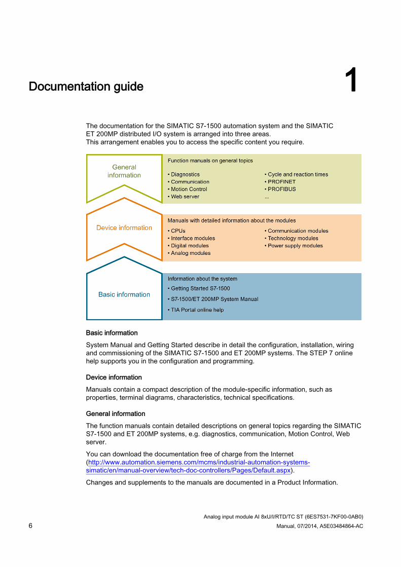
The documentation for the SIMATIC S7-1500 automation system and the SIMATIC ET 200MP distributed I/O system is arranged into three areas. This arrangement enables you to access the specific content you require.
Basic information
System Manual and Getting Started describe in detail the configuration, installation, wiring and commissioning of the SIMATIC S7-1500 and ET 200MP systems. The STEP 7 online help supports you in the configuration and programming.
Device information
Manuals contain a compact description of the module-specific information, such as properties, terminal diagrams, characteristics, technical specifications.
General information
The function manuals contain detailed descriptions on general topics regarding the SIMATIC S7-1500 and ET 200MP systems, e.g. diagnostics, communication, Motion Control, Web server.
You can download the documentation free of charge from the Internet (http://www.automation.siemens.com/mcms/industrial-automation-systems-simatic/en/manual-overview/tech-doc-controllers/Pages/Default.aspx).
Changes and supplements to the manuals are documented in a Product Information.
Documentation guide
Analog input module AI 8xU/I/RTD/TC ST (6ES7531-7KF00-0AB0) Manual, 07/2014, A5E03484864-AC 7
Manual Collection S7-1500 / ET 200MP The Manual Collection contains the complete documentation on the SIMATIC S7-1500 automation system and the ET 200MP distributed I/O system gathered together in one file.
You can find the Manual Collection on the Internet (http://support.automation.siemens.com/WW/view/en/86140384).
My Documentation Manager The My Documentation Manager is used to combine entire manuals or only parts of these to your own manual. You can export the manual as PDF file or in a format that can be edited later.
You can find the My Documentation Manager on the Internet (http://support.automation.siemens.com/WW/view/en/38715968).
Applications & Tools Applications & Tools supports you with various tools and examples for solving your automation tasks. Solutions are shown in interplay with multiple components in the system - separated from the focus in individual products.
You can find Applications & Tools on the Internet (http://support.automation.siemens.com/WW/view/en/20208582).
CAx Download Manager The CAx Download Manager is used to access the current product data for your CAx or CAe systems.
You configure your own download package with a few clicks.
In doing so you can select:
Product images, 2D dimension drawings, 3D models, internal circuit diagrams, EPLAN macro files
Manuals, characteristics, operating manuals, certificates
Product master data
You can find the CAx Download Manager on the Internet (http://support.automation.siemens.com/WW/view/en/42455541).
Analog input module AI 8xU/I/RTD/TC ST (6ES7531-7KF00-0AB0) 8 Manual, 07/2014, A5E03484864-AC
Product overview 2 2.1 Properties
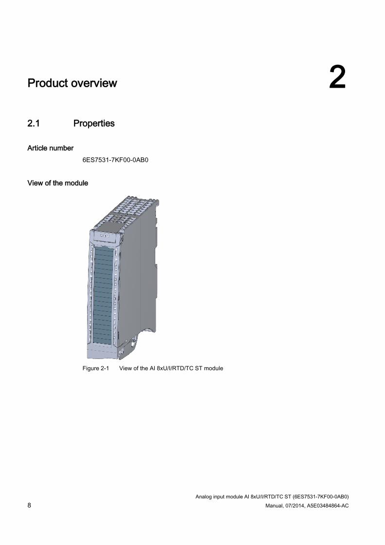
Article number 6ES7531-7KF00-0AB0
View of the module
Figure 2-1 View of the AI 8xU/I/RTD/TC ST module
Product overview 2.1 Properties
Analog input module AI 8xU/I/RTD/TC ST (6ES7531-7KF00-0AB0) Manual, 07/2014, A5E03484864-AC 9
Properties The module has the following technical properties:
8 analog inputs
Voltage measuring type can be set per channel
Current measuring type can be set per channel
Measuring type resistance adjustable for channel 0, 2, 4 and 6
Measuring type resistance thermometers (RTD) adjustable for channel 0, 2, 4 and 6
Thermocouple (TC) measuring type can be set per channel
Resolution 16 bits including sign
Configurable diagnostics (per channel)
Hardware interrupt on limit violation can be set per channel (two low and two high limits per channel)
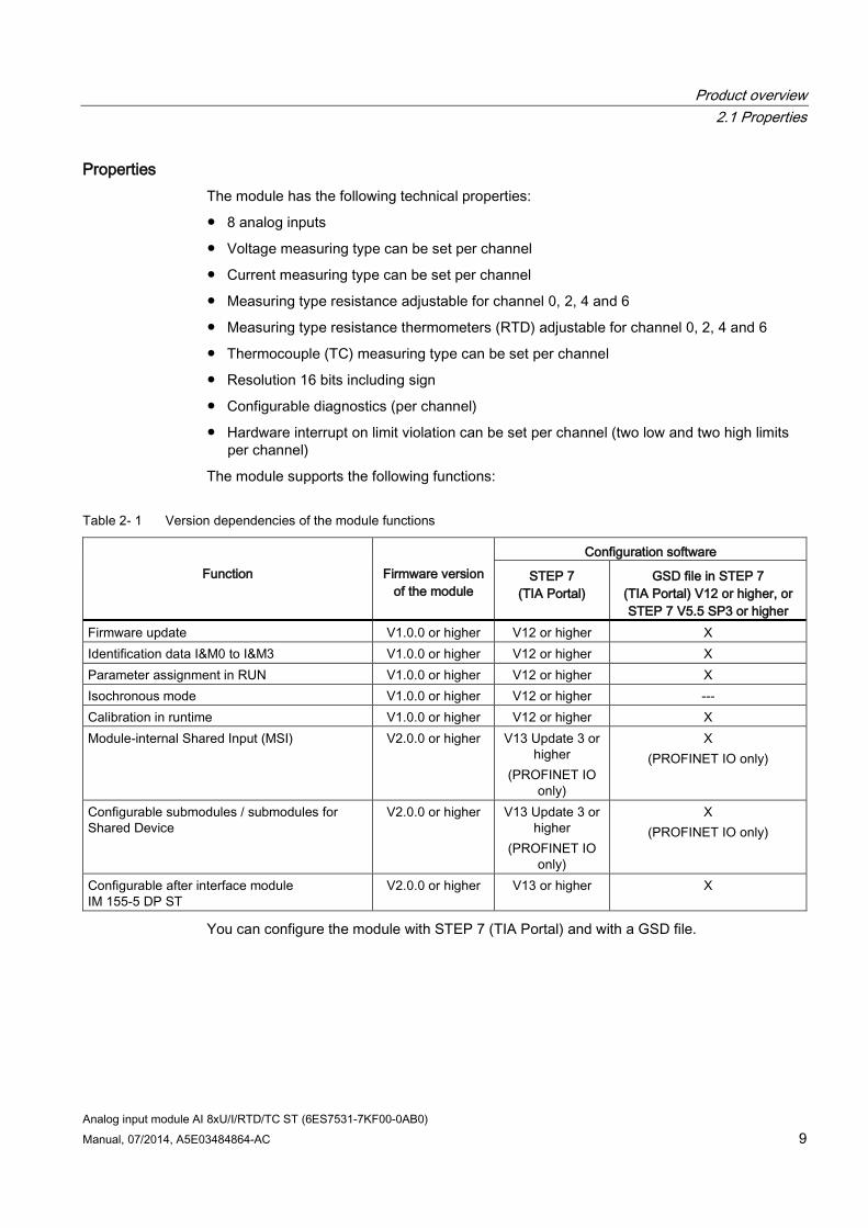
The module supports the following functions:
Table 2- 1 Version dependencies of the module functions
Function
Firmware version
of the module
Configuration software
STEP 7 (TIA Portal)
GSD file in STEP 7 (TIA Portal) V12 or higher, or STEP 7 V5.5 SP3 or higher
Firmware update V1.0.0 or higher V12 or higher X Identification data I&M0 to I&M3 V1.0.0 or higher V12 or higher X Parameter assignment in RUN V1.0.0 or higher V12 or higher X Isochronous mode V1.0.0 or higher V12 or higher --- Calibration in runtime V1.0.0 or higher V12 or higher X Module-internal Shared Input (MSI) V2.0.0 or higher V13 Update 3 or
higher (PROFINET IO
only)
X (PROFINET IO only)
Configurable submodules / submodules for Shared Device
V2.0.0 or higher V13 Update 3 or higher
(PROFINET IO only)
X (PROFINET IO only)
Configurable after interface module IM 155-5 DP ST
V2.0.0 or higher V13 or higher X
You can configure the module with STEP 7 (TIA Portal) and with a GSD file.
Product overview 2.1 Properties
Analog input module AI 8xU/I/RTD/TC ST (6ES7531-7KF00-0AB0) 10 Manual, 07/2014, A5E03484864-AC
Accessories The following accessories are supplied with the module and can also be ordered separately as spare parts:
Shield bracket
Shield terminal
Power supply element
Labeling strips
U connector
Universal front door
Other components The following component must be ordered separately:
Front connectors, including potential jumpers and cable ties
You can find more information on accessories in the S7-1500 Automation System system manual (http://support.automation.siemens.com/WW/view/en/59191792) and the ET 200MP Distributed I/O System system manual (http://support.automation.siemens.com/WW/view/en/59193214).
Analog input module AI 8xU/I/RTD/TC ST (6ES7531-7KF00-0AB0) Manual, 07/2014, A5E03484864-AC 11
Wiring 3
This section contains the block diagram of the module and outlines various connection options.
For more information on front connector wiring and creating cable shields, etc., refer to the "Wiring" section in the Automation System S7-1500 (http://support.automation.siemens.com/WW/view/en/59191792) and Distributed I/O System ET 200MP (http://support.automation.siemens.com/WW/view/en/59193214) system manuals.
You can find additional information on compensating the reference junction temperature in the function manual Analog value processing (http://support.automation.siemens.com/WW/view/en/67989094), the structure of a data record in the section Structure of a data record for dynamic reference temperature (Page 61).
Note
You may use and combine the different wiring options for all channels.
Note
Do not insert the potential jumpers included with the front connector!
Abbreviations used Meaning of the abbreviations used in the following figures: Un+/Un- Voltage input channel n (voltage only) Mn+/Mn- Measuring input channel n In+/In- Current input channel n (current only) Ic n+/Ic n- Current output for RTD, channel n UVn Supply voltage at channel n for 2-wire transmitters (2WT) Comp+/Comp- Compensation input IComp+/IComp- Current output for compensation L+ Supply voltage connection M Ground connection MANA Reference potential of the analog circuit CHx Channel or display of the channel status PWR Display for the supply voltage
Wiring
Analog input module AI 8xU/I/RTD/TC ST (6ES7531-7KF00-0AB0) 12 Manual, 07/2014, A5E03484864-AC
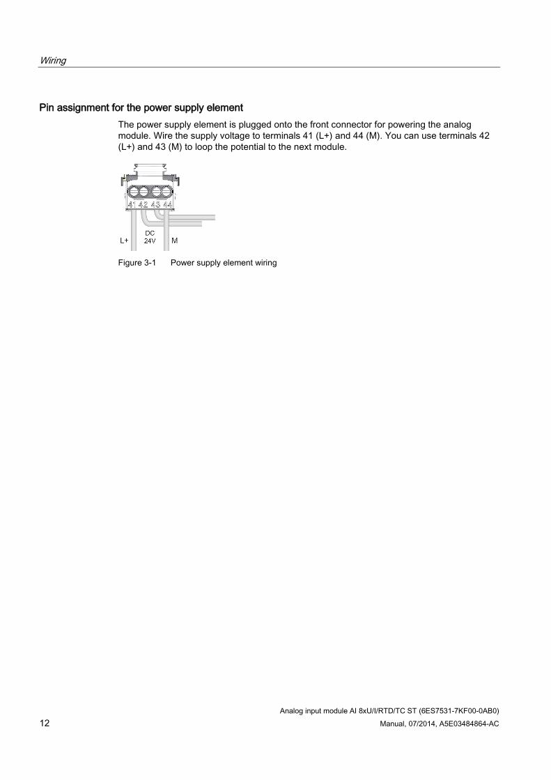
Pin assignment for the power supply element The power supply element is plugged onto the front connector for powering the analog module. Wire the supply voltage to terminals 41 (L+) and 44 (M). You can use terminals 42 (L+) and 43 (M) to loop the potential to the next module.
Figure 3-1 Power supply element wiring
Wiring
Analog input module AI 8xU/I/RTD/TC ST (6ES7531-7KF00-0AB0) Manual, 07/2014, A5E03484864-AC 13
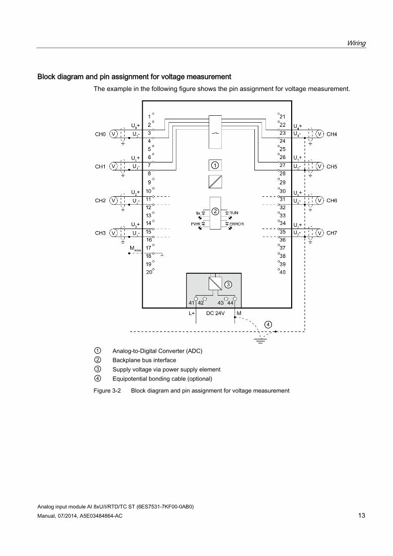
Block diagram and pin assignment for voltage measurement The example in the following figure shows the pin assignment for voltage measurement.
① Analog-to-Digital Converter (ADC) ② Backplane bus interface ③ Supply voltage via power supply element ④ Equipotential bonding cable (optional)
Figure 3-2 Block diagram and pin assignment for voltage measurement
Wiring
Analog input module AI 8xU/I/RTD/TC ST (6ES7531-7KF00-0AB0) 14 Manual, 07/2014, A5E03484864-AC
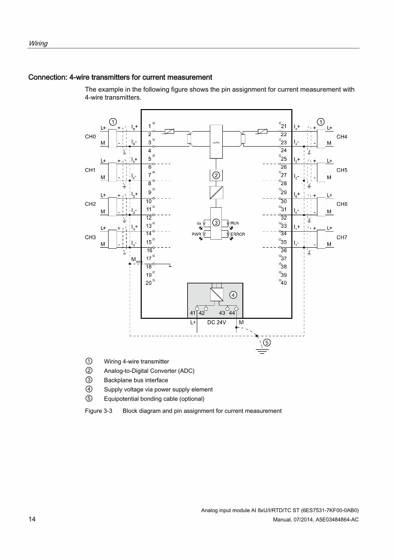
Connection: 4-wire transmitters for current measurement The example in the following figure shows the pin assignment for current measurement with 4-wire transmitters.
① Wiring 4-wire transmitter ② Analog-to-Digital Converter (ADC) ③ Backplane bus interface ④ Supply voltage via power supply element ⑤ Equipotential bonding cable (optional)
Figure 3-3 Block diagram and pin assignment for current measurement
Wiring
Analog input module AI 8xU/I/RTD/TC ST (6ES7531-7KF00-0AB0) Manual, 07/2014, A5E03484864-AC 15
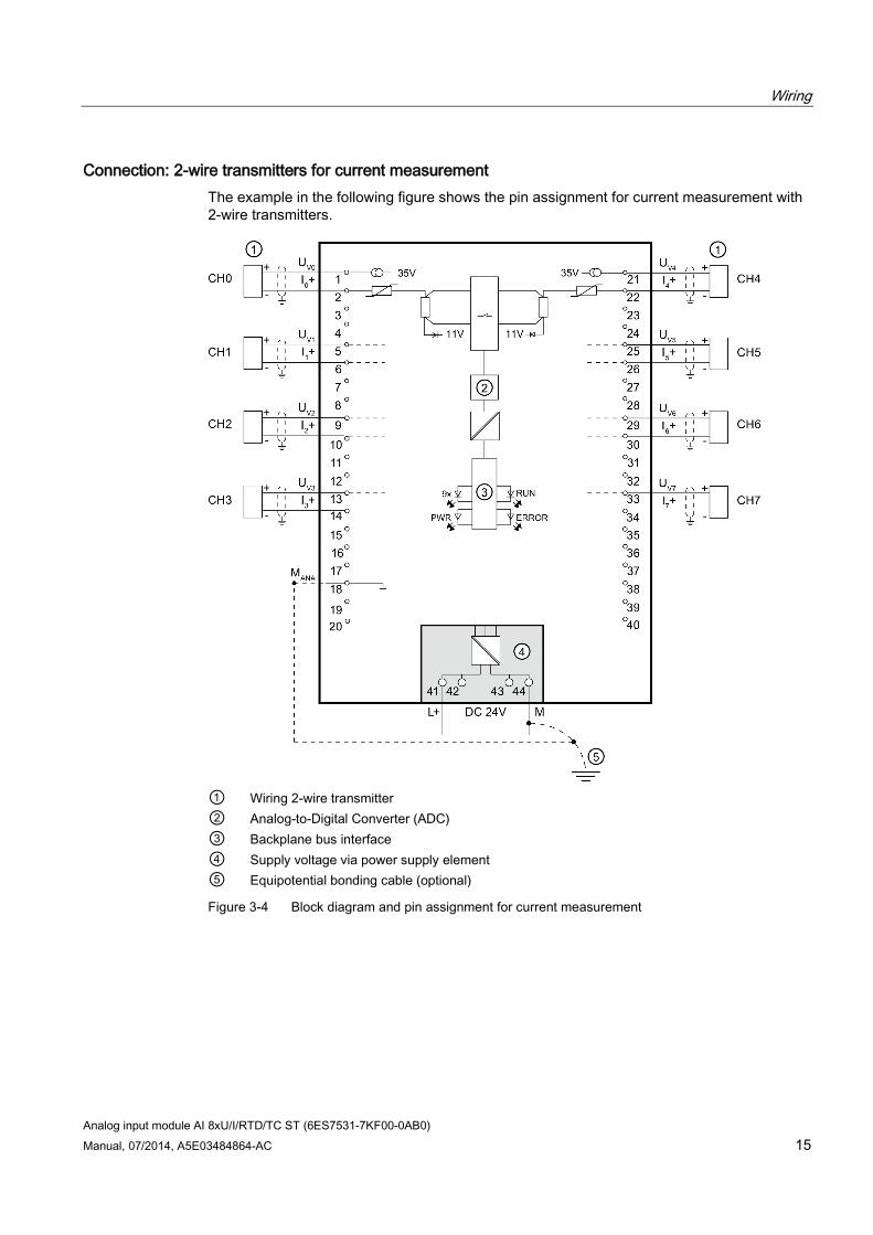
Connection: 2-wire transmitters for current measurement The example in the following figure shows the pin assignment for current measurement with 2-wire transmitters.
① Wiring 2-wire transmitter ② Analog-to-Digital Converter (ADC) ③ Backplane bus interface ④ Supply voltage via power supply element ⑤ Equipotential bonding cable (optional)
Figure 3-4 Block diagram and pin assignment for current measurement
Wiring
Analog input module AI 8xU/I/RTD/TC ST (6ES7531-7KF00-0AB0) 16 Manual, 07/2014, A5E03484864-AC
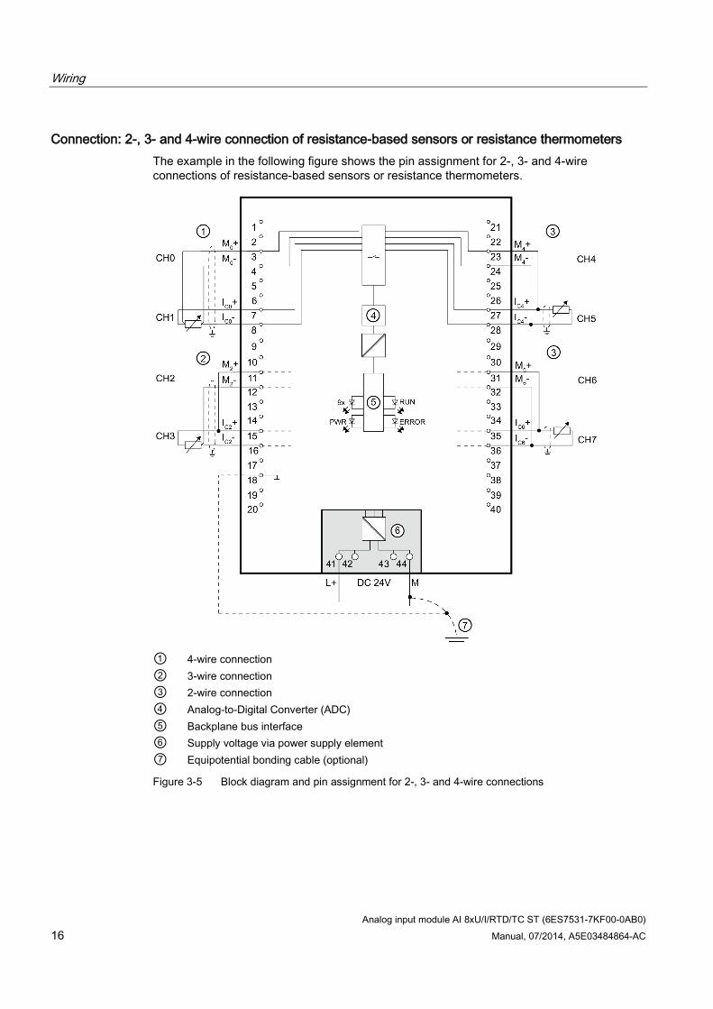
Connection: 2-, 3- and 4-wire connection of resistance-based sensors or resistance thermometers The example in the following figure shows the pin assignment for 2-, 3- and 4-wire connections of resistance-based sensors or resistance thermometers.
① 4-wire connection ② 3-wire connection ③ 2-wire connection ④ Analog-to-Digital Converter (ADC) ⑤ Backplane bus interface ⑥ Supply voltage via power supply element ⑦ Equipotential bonding cable (optional)
Figure 3-5 Block diagram and pin assignment for 2-, 3- and 4-wire connections
Wiring
Analog input module AI 8xU/I/RTD/TC ST (6ES7531-7KF00-0AB0) Manual, 07/2014, A5E03484864-AC 17
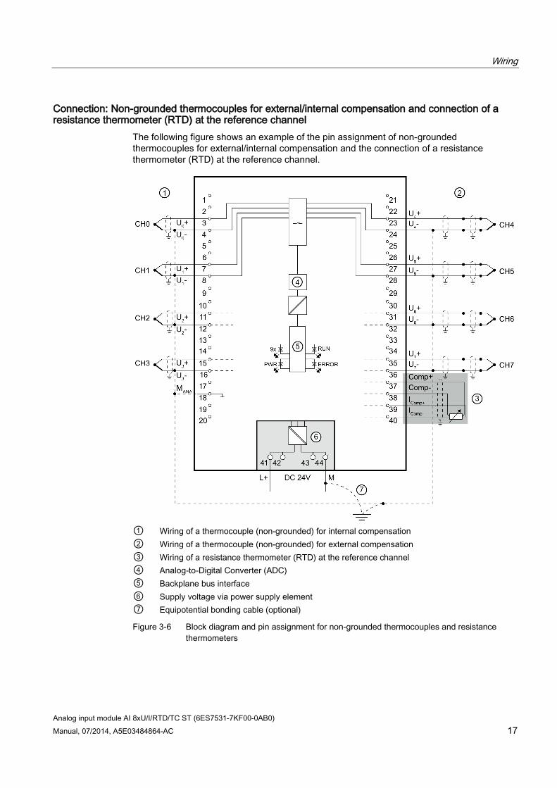
Connection: Non-grounded thermocouples for external/internal compensation and connection of a resistance thermometer (RTD) at the reference channel
The following figure shows an example of the pin assignment of non-grounded thermocouples for external/internal compensation and the connection of a resistance thermometer (RTD) at the reference channel.
① Wiring of a thermocouple (non-grounded) for internal compensation ② Wiring of a thermocouple (non-grounded) for external compensation ③ Wiring of a resistance thermometer (RTD) at the reference channel ④ Analog-to-Digital Converter (ADC) ⑤ Backplane bus interface ⑥ Supply voltage via power supply element ⑦ Equipotential bonding cable (optional)
Figure 3-6 Block diagram and pin assignment for non-grounded thermocouples and resistance thermometers
Wiring
Analog input module AI 8xU/I/RTD/TC ST (6ES7531-7KF00-0AB0) 18 Manual, 07/2014, A5E03484864-AC
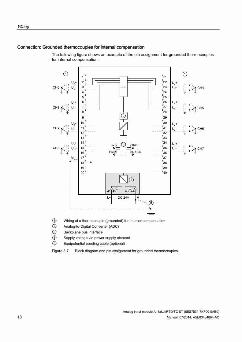
Connection: Grounded thermocouples for internal compensation The following figure shows an example of the pin assignment for grounded thermocouples for internal compensation.
① Wiring of a thermocouple (grounded) for internal compensation ② Analog-to-Digital Converter (ADC) ③ Backplane bus interface ④ Supply voltage via power supply element ⑤ Equipotential bonding cable (optional)
Figure 3-7 Block diagram and pin assignment for grounded thermocouples
Analog input module AI 8xU/I/RTD/TC ST (6ES7531-7KF00-0AB0) Manual, 07/2014, A5E03484864-AC 19
Parameters/address space 4 4.1 Measuring types and ranges
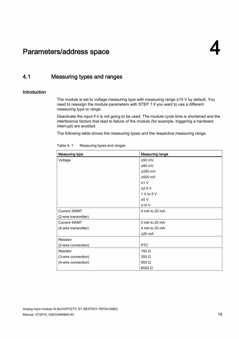
Introduction The module is set to voltage measuring type with measuring range ±10 V by default. You need to reassign the module parameters with STEP 7 if you want to use a different measuring type or range.
Deactivate the input if it is not going to be used. The module cycle time is shortened and the interference factors that lead to failure of the module (for example, triggering a hardware interrupt) are avoided.
The following table shows the measuring types and the respective measuring range.
Table 4- 1 Measuring types and ranges
Measuring type Measuring range Voltage ±50 mV
±80 mV ±250 mV ±500 mV ±1 V ±2.5 V 1 V to 5 V ±5 V ±10 V
Current 2WMT (2-wire transmitter)
4 mA to 20 mA
Current 4WMT (4-wire transmitter)
0 mA to 20 mA 4 mA to 20 mA ±20 mA
Resistor (2-wire connection)
PTC
Resistor (3-wire connection) (4-wire connection)
150 Ω 300 Ω 600 Ω 6000 Ω
Parameters/address space 4.1 Measuring types and ranges
Analog input module AI 8xU/I/RTD/TC ST (6ES7531-7KF00-0AB0) 20 Manual, 07/2014, A5E03484864-AC
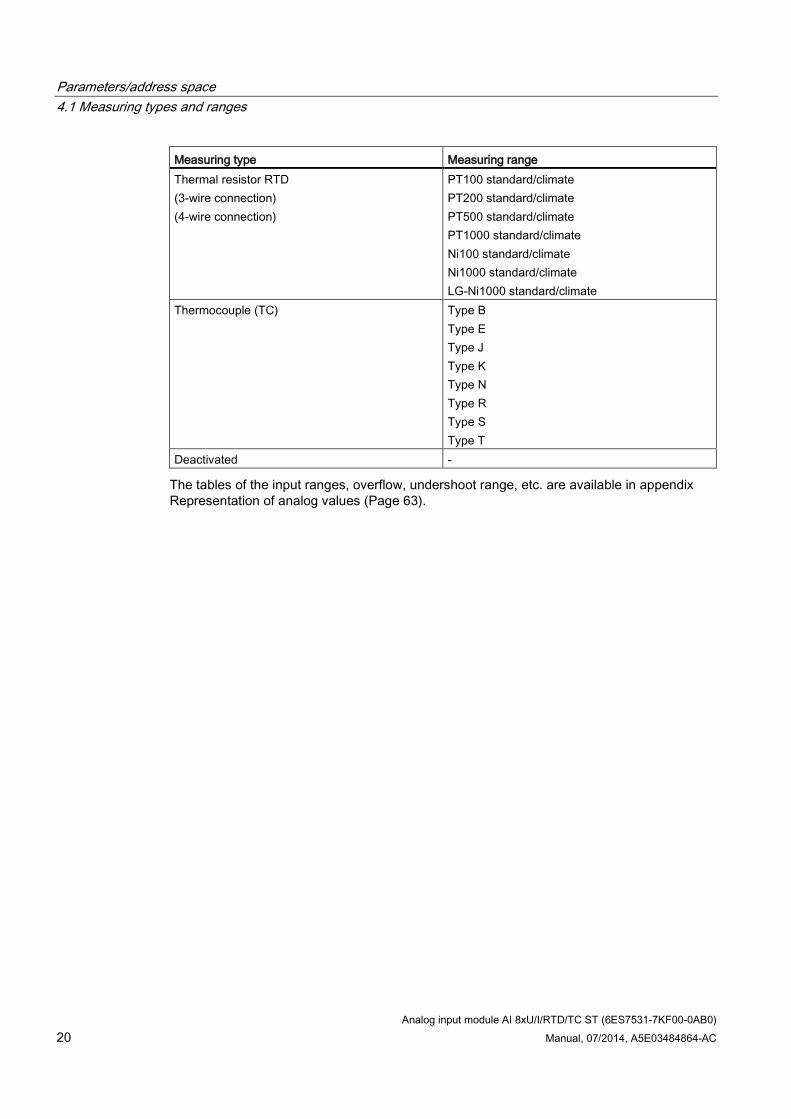
Measuring type Measuring range Thermal resistor RTD (3-wire connection) (4-wire connection)
PT100 standard/climate PT200 standard/climate PT500 standard/climate PT1000 standard/climate Ni100 standard/climate Ni1000 standard/climate LG-Ni1000 standard/climate
Thermocouple (TC) Type B Type E Type J Type K Type N Type R Type S Type T
Deactivated -
The tables of the input ranges, overflow, undershoot range, etc. are available in appendix Representation of analog values (Page 63).
Parameters/address space 4.1 Measuring types and ranges
Analog input module AI 8xU/I/RTD/TC ST (6ES7531-7KF00-0AB0) Manual, 07/2014, A5E03484864-AC 21
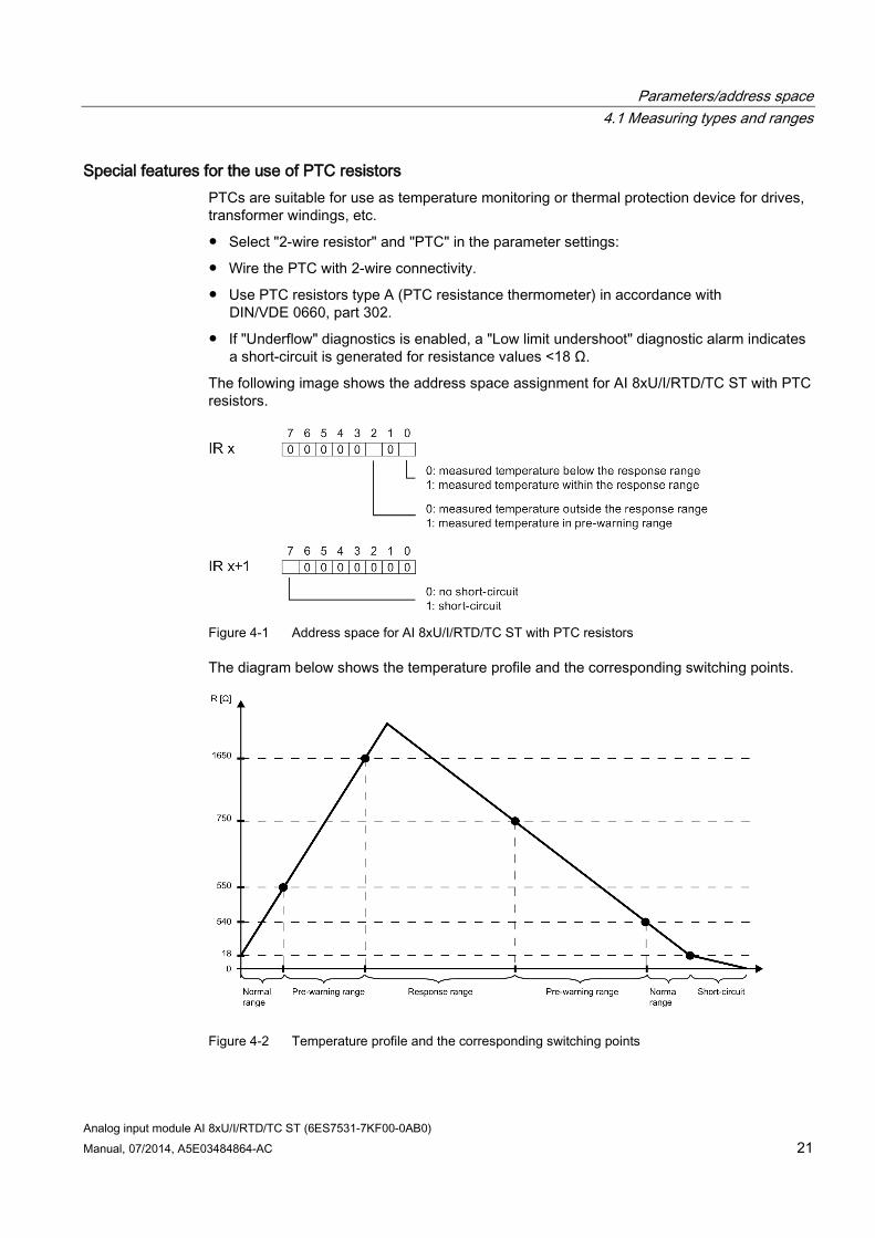
Special features for the use of PTC resistors PTCs are suitable for use as temperature monitoring or thermal protection device for drives, transformer windings, etc.
Select "2-wire resistor" and "PTC" in the parameter settings:
Wire the PTC with 2-wire connectivity.
Use PTC resistors type A (PTC resistance thermometer) in accordance with DIN/VDE 0660, part 302.
If "Underflow" diagnostics is enabled, a "Low limit undershoot" diagnostic alarm indicates a short-circuit is generated for resistance values <18 Ω.
The following image shows the address space assignment for AI 8xU/I/RTD/TC ST with PTC resistors.
Figure 4-1 Address space for AI 8xU/I/RTD/TC ST with PTC resistors
The diagram below shows the temperature profile and the corresponding switching points.
Figure 4-2 Temperature profile and the corresponding switching points
Parameters/address space 4.2 Parameters
Analog input module AI 8xU/I/RTD/TC ST (6ES7531-7KF00-0AB0) 22 Manual, 07/2014, A5E03484864-AC
Special features of the measured value acquisition with PTC resistors If faults occur (for example supply voltage L+ missing) that make it impossible to acquire measured values with PTC resistors, the corresponding channels (IR x/IR x+1) report overflow (7FFFH). If the value status (QI) is enabled, the value 0 = fault is output in the corresponding bit.
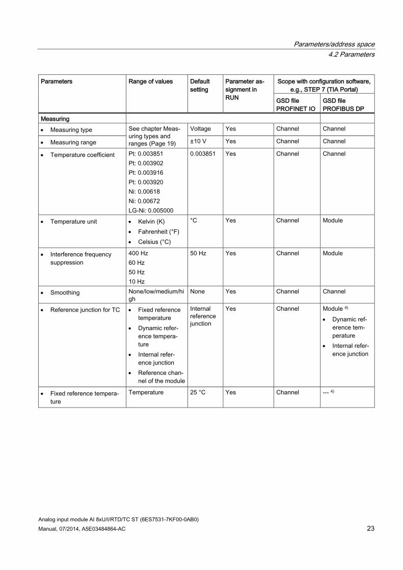
4.2 Parameters
AI 8xU/I/RTD/TC ST parameters When you assign the module parameters in STEP 7, you use various parameters to specify the module properties. The following table lists the configurable parameters. The effective range of the configurable parameters depends on the type of configuration. The following configurations are possible:
Central operation with a S7-1500 CPU
Distributed operation on PROFINET IO in an ET 200MP system
Distributed operation on PROFIBUS DP in an ET 200MP system
When assigning parameters in the user program, use the WRREC instruction to transfer the parameters to the module by means of data records; refer to the section Parameter assignment and structure of the parameter data records (Page 49).
The following parameter settings for the channels are possible:
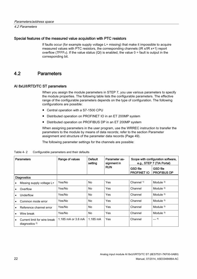
Table 4- 2 Configurable parameters and their defaults
Parameters Range of values Default setting
Parameter as-signment in RUN
Scope with configuration software, e.g., STEP 7 (TIA Portal)
GSD file PROFINET IO
GSD file PROFIBUS DP
Diagnostics
• Missing supply voltage L+ Yes/No No Yes Channel 1) Module 3)
• Overflow Yes/No No Yes Channel Module 3)
• Underflow Yes/No No Yes Channel Module 3)
• Common mode error Yes/No No Yes Channel Module 3)
• Reference channel error Yes/No No Yes Channel Module 3)
• Wire break Yes/No No Yes Channel Module 3)
• Current limit for wire break diagnostics 2)
1.185 mA or 3.6 mA 1.185 mA Yes Channel --- 4)
Parameters/address space 4.2 Parameters
Analog input module AI 8xU/I/RTD/TC ST (6ES7531-7KF00-0AB0) Manual, 07/2014, A5E03484864-AC 23
Parameters Range of values Default setting
Parameter as-signment in RUN
Scope with configuration software, e.g., STEP 7 (TIA Portal)
GSD file PROFINET IO
GSD file PROFIBUS DP
Measuring
• Measuring type See chapter Meas-uring types and ranges (Page 19)
Voltage Yes Channel Channel
• Measuring range ±10 V Yes Channel Channel
• Temperature coefficient Pt: 0.003851 Pt: 0.003902 Pt: 0.003916 Pt: 0.003920 Ni: 0.00618 Ni: 0.00672 LG-Ni: 0.005000
0.003851 Yes Channel Channel
• Temperature unit • Kelvin (K) • Fahrenheit (°F) • Celsius (°C)
°C Yes Channel Module
• Interference frequency suppression
400 Hz 60 Hz 50 Hz 10 Hz
50 Hz Yes Channel Module
• Smoothing None/low/medium/high
None Yes Channel Channel
• Reference junction for TC • Fixed reference temperature
• Dynamic refer-ence tempera-ture
• Internal refer-ence junction
• Reference chan-nel of the module
Internal reference junction
Yes Channel Module 4) • Dynamic ref-
erence tem-perature
• Internal refer-ence junction
• Fixed reference tempera-ture
Temperature 25 °C Yes Channel --- 4)
Parameters/address space 4.2 Parameters
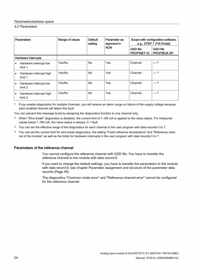
Analog input module AI 8xU/I/RTD/TC ST (6ES7531-7KF00-0AB0) 24 Manual, 07/2014, A5E03484864-AC
Parameters Range of values Default setting
Parameter as-signment in RUN
Scope with configuration software, e.g., STEP 7 (TIA Portal)
GSD file PROFINET IO
GSD file PROFIBUS DP
Hardware interrupts
• Hardware interrupt low limit 1
Yes/No No Yes Channel --- 4)
• Hardware interrupt high limit 1
Yes/No No Yes Channel --- 4)
• Hardware interrupt low limit 2
Yes/No No Yes Channel --- 4)
• Hardware interrupt high limit 2
Yes/No No Yes Channel --- 4)
1) If you enable diagnostics for multiple channels, you will receive an alarm surge on failure of the supply voltage because each enabled channel will detect this fault.
You can prevent this message burst by assigning the diagnostics function to one channel only. 2) When "Wire break" diagnostics is disabled, the current limit of 1.185 mA is applied to the value status. For measured
values below 1.185 mA, the value status is always: 0 = fault. 3) You can set the effective range of the diagnostics for each channel in the user program with data records 0 to 7. 4) You can set the current limit for wire break diagnostics, the setting "Fixed reference temperature" and "Reference chan-
nel of the module" as well as the limits for hardware interrupts in the user program with data records 0 to 7.
Parameters of the reference channel You cannot configure the reference channel with GSD file. You have to transfer the reference channel to the module with data record 8.
If you want to change the default settings, you have to transfer the parameters to the module with data record 8, see chapter Parameter assignment and structure of the parameter data records (Page 49).
The diagnostics "Common mode error" and "Reference channel error" cannot be configured for the reference channel.
Parameters/address space 4.3 Declaration of parameters
Analog input module AI 8xU/I/RTD/TC ST (6ES7531-7KF00-0AB0) Manual, 07/2014, A5E03484864-AC 25
4.3 Declaration of parameters
Missing supply voltage L+ Enabling of the diagnostics, with missing or too little supply voltage L+.
Overflow Enabling of the diagnostics if the measured value violates the high limit.
Underflow Enabling of the diagnostics when the measured value falls below the underrange or for voltage measurement ranges of ± 50 mV to ± 2.5 V if the inputs are not connected.
Common mode error Enable diagnostics if the valid common mode voltage is exceeded. Enable the Common mode error diagnostics when 2WMT is connected, for example, to check for a short circuit to MANA or a wire break. If you do not need the Common mode error diagnostics, disable the parameter.
Reference channel error Enable diagnostics for an error at the temperature compensation channel, e.g. wire
break.
Dynamic reference temperature compensation type is configured and no reference temperature has been transferred to the module yet.
Wire break Enabling of the diagnostics if the module has no current flow or the current is too weak for the measurement at the corresponding configured input or the applied voltage is too low.
Current limit for wire break diagnostics Threshold for reporting wire breaks. The value can be set to 1.185 mA or 3.6 mA, depending on the sensor used.
Temperature coefficient The temperature coefficient depends on the chemical composition of the material. In Europe, only one value is used per sensor type (default value). The temperature coefficient (α value) indicates by how much the resistance of a specific material changes relatively if the temperature increases by 1 °C. The further values facilitate a sensor-specific setting of the temperature coefficient and enhance accuracy.
Parameters/address space 4.3 Declaration of parameters
Analog input module AI 8xU/I/RTD/TC ST (6ES7531-7KF00-0AB0) 26 Manual, 07/2014, A5E03484864-AC
Interference frequency suppression At analog input modules, this suppresses interference caused by the frequency of AC mains.
The frequency of AC network may corrupt measurements, particularly in the low voltage ranges, and when thermocouples are being used. For this parameter, the user defines the mains frequency prevailing on his system.
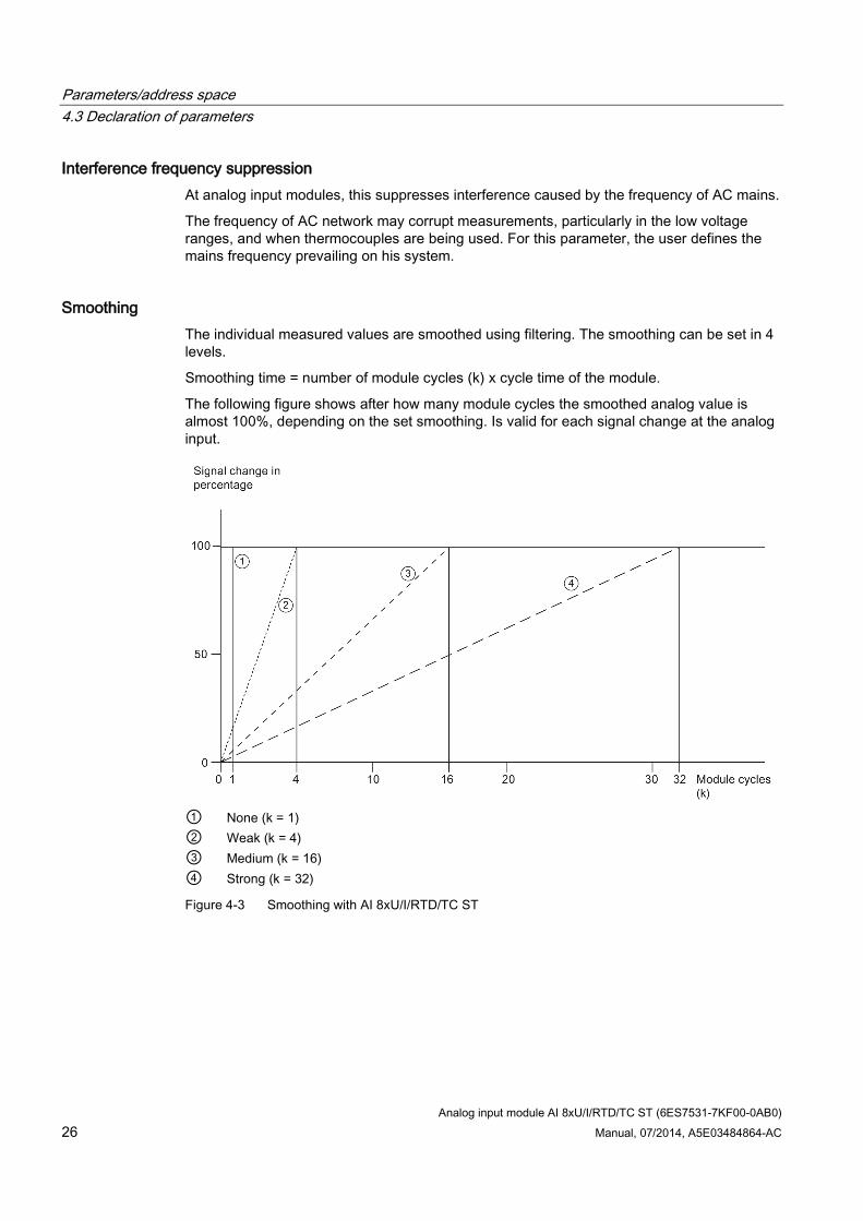
Smoothing The individual measured values are smoothed using filtering. The smoothing can be set in 4 levels.
Smoothing time = number of module cycles (k) x cycle time of the module.
The following figure shows after how many module cycles the smoothed analog value is almost 100%, depending on the set smoothing. Is valid for each signal change at the analog input.
① None (k = 1) ② Weak (k = 4) ③ Medium (k = 16) ④ Strong (k = 32)
Figure 4-3 Smoothing with AI 8xU/I/RTD/TC ST
Parameters/address space 4.3 Declaration of parameters
Analog input module AI 8xU/I/RTD/TC ST (6ES7531-7KF00-0AB0) Manual, 07/2014, A5E03484864-AC 27
Reference junction for TC The following settings can be configured for the reference junction parameter:
Table 4- 3 Possible parameter assignments for the reference junction parameter TC
Setting Description Fixed reference temperature The reference junction temperature is configured and stored in the module as
a fixed value. Dynamic reference temperature The reference junction temperature is transferred in the user program from the
CPU to the module by data records 192 to 199 using the WRREC (SFB 53) instruction.
Internal reference junction The reference junction temperature is determined using an integrated sensor of the module.
Reference channel of the module The reference junction temperature is determined using an external resistance thermometer (RTD) at the reference channel (COMP) of the module.
Hardware interrupt 1 or 2 Enable a hardware interrupt at violation of high limit 1 or 2 or low limit 1 or 2.
Low limit 1 or 2 Specifies the low limit threshold that triggers hardware interrupt 1 or 2.
High limit 1 or 2 Specifies the high limit threshold that triggers hardware interrupt 1 or 2.
Parameters/address space 4.4 Address space
Analog input module AI 8xU/I/RTD/TC ST (6ES7531-7KF00-0AB0) 28 Manual, 07/2014, A5E03484864-AC
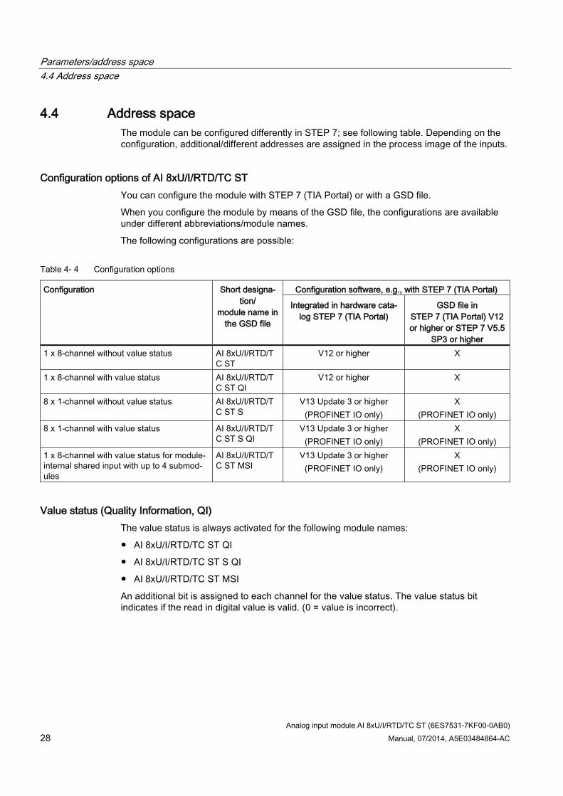
4.4 Address space The module can be configured differently in STEP 7; see following table. Depending on the configuration, additional/different addresses are assigned in the process image of the inputs.
Configuration options of AI 8xU/I/RTD/TC ST You can configure the module with STEP 7 (TIA Portal) or with a GSD file.
When you configure the module by means of the GSD file, the configurations are available under different abbreviations/module names.
The following configurations are possible:
Table 4- 4 Configuration options
Configuration Short designa-tion/
module name in the GSD file
Configuration software, e.g., with STEP 7 (TIA Portal)
Integrated in hardware cata-log STEP 7 (TIA Portal)
GSD file in STEP 7 (TIA Portal) V12 or higher or STEP 7 V5.5
SP3 or higher 1 x 8-channel without value status AI 8xU/I/RTD/T
C ST V12 or higher X
1 x 8-channel with value status AI 8xU/I/RTD/TC ST QI
V12 or higher X
8 x 1-channel without value status AI 8xU/I/RTD/TC ST S
V13 Update 3 or higher (PROFINET IO only)
X (PROFINET IO only)
8 x 1-channel with value status AI 8xU/I/RTD/TC ST S QI
V13 Update 3 or higher (PROFINET IO only)
X (PROFINET IO only)
1 x 8-channel with value status for module-internal shared input with up to 4 submod-ules
AI 8xU/I/RTD/TC ST MSI
V13 Update 3 or higher (PROFINET IO only)
X (PROFINET IO only)
Value status (Quality Information, QI) The value status is always activated for the following module names:
AI 8xU/I/RTD/TC ST QI
AI 8xU/I/RTD/TC ST S QI
AI 8xU/I/RTD/TC ST MSI
An additional bit is assigned to each channel for the value status. The value status bit indicates if the read in digital value is valid. (0 = value is incorrect).
Parameters/address space 4.4 Address space
Analog input module AI 8xU/I/RTD/TC ST (6ES7531-7KF00-0AB0) Manual, 07/2014, A5E03484864-AC 29
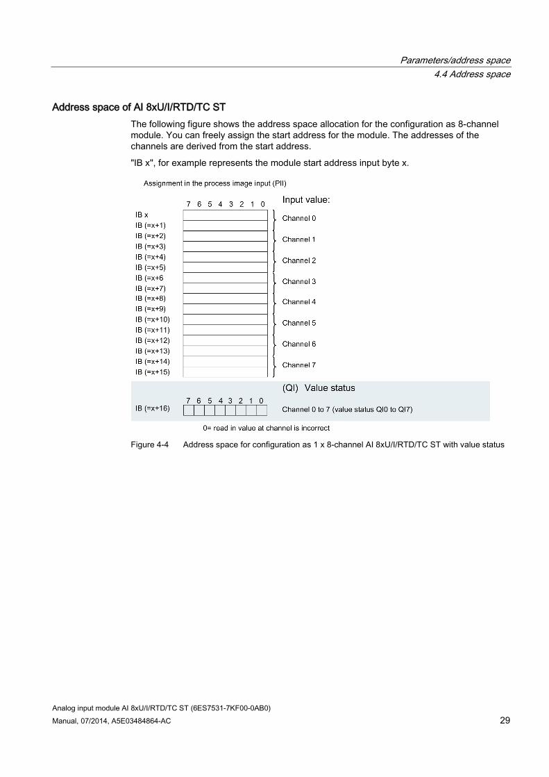
Address space of AI 8xU/I/RTD/TC ST The following figure shows the address space allocation for the configuration as 8-channel module. You can freely assign the start address for the module. The addresses of the channels are derived from the start address.
"IB x", for example represents the module start address input byte x.
Figure 4-4 Address space for configuration as 1 x 8-channel AI 8xU/I/RTD/TC ST with value status
Parameters/address space 4.4 Address space
Analog input module AI 8xU/I/RTD/TC ST (6ES7531-7KF00-0AB0) 30 Manual, 07/2014, A5E03484864-AC
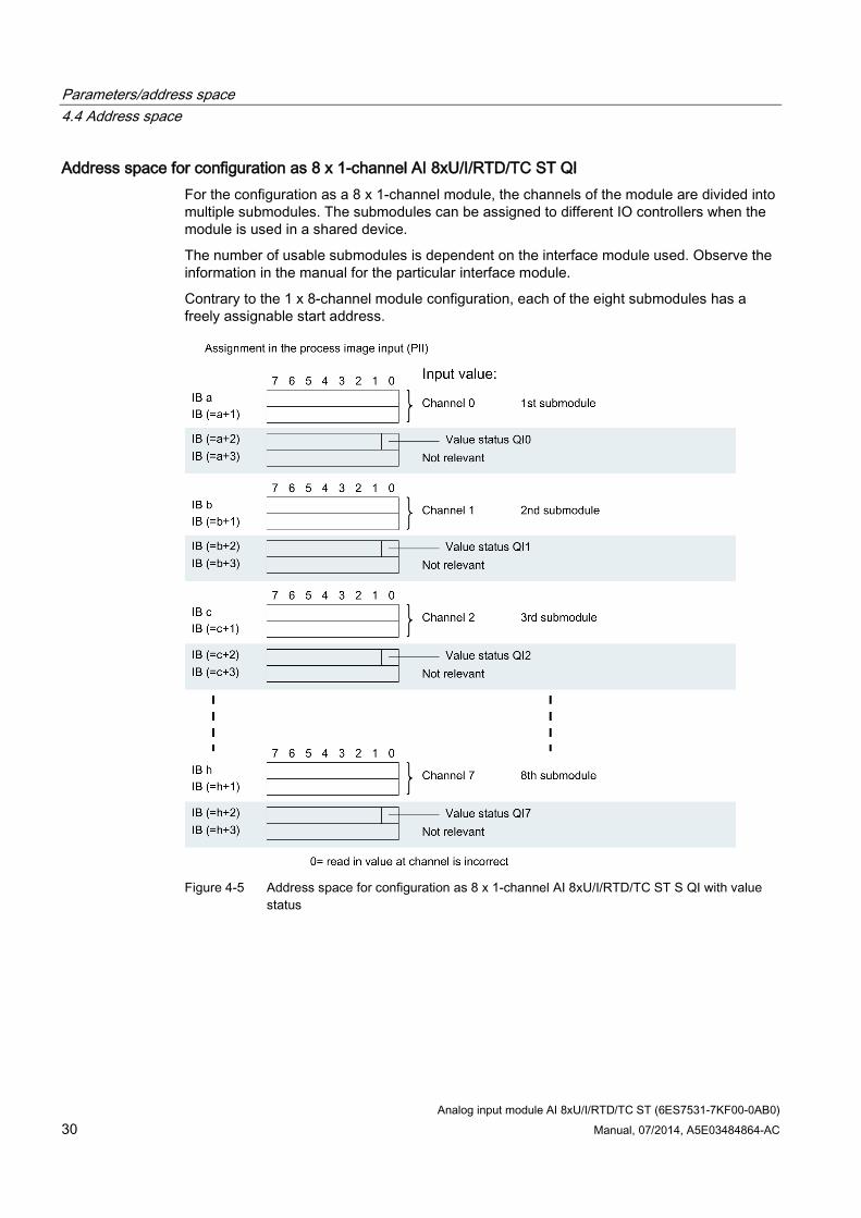
Address space for configuration as 8 x 1-channel AI 8xU/I/RTD/TC ST QI For the configuration as a 8 x 1-channel module, the channels of the module are divided into multiple submodules. The submodules can be assigned to different IO controllers when the module is used in a shared device.
The number of usable submodules is dependent on the interface module used. Observe the information in the manual for the particular interface module.
Contrary to the 1 x 8-channel module configuration, each of the eight submodules has a freely assignable start address.
Figure 4-5 Address space for configuration as 8 x 1-channel AI 8xU/I/RTD/TC ST S QI with value
status
Parameters/address space 4.4 Address space
Analog input module AI 8xU/I/RTD/TC ST (6ES7531-7KF00-0AB0) Manual, 07/2014, A5E03484864-AC 31
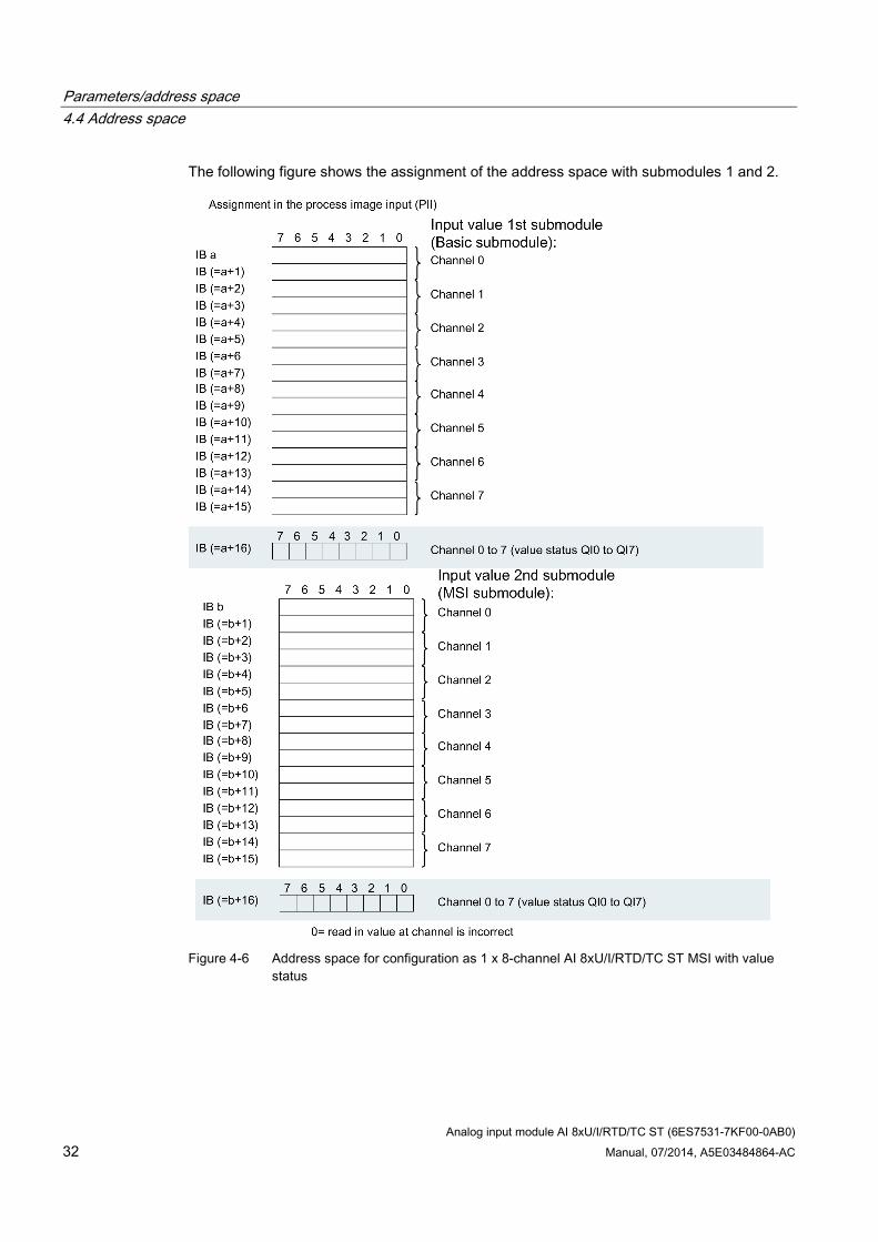
Address space for configuration as 1 x 8-channel AI 8xU/I/RTD/TC ST MSI The channels 0 to 7 of the module are copied in up to four submodules with configuration 1 x 8-channel module (Module-internal shared input, MSI). Channels 0 to 7 are then available with identical input values in different submodules. These submodules can be assigned to up to four IO controllers when the module is used in a shared device. Each IO controller has read access to the same channels.
The number of usable submodules is dependent on the interface module used. Please observe the information in the manual for the particular interface module.
Value status (Quality Information, QI)
The meaning of the value status depends on the submodule on which it occurs.
For the first submodule (=basic submodule), the value status 0 indicates that the value is incorrect.
For the 2nd to 4th submodule (=MSI submodule), the value status 0 indicates that the value is incorrect or the basic submodule has not yet been configured (not ready).
Parameters/address space 4.4 Address space
Analog input module AI 8xU/I/RTD/TC ST (6ES7531-7KF00-0AB0) 32 Manual, 07/2014, A5E03484864-AC
The following figure shows the assignment of the address space with submodules 1 and 2.
Figure 4-6 Address space for configuration as 1 x 8-channel AI 8xU/I/RTD/TC ST MSI with value
status
Parameters/address space 4.4 Address space
Analog input module AI 8xU/I/RTD/TC ST (6ES7531-7KF00-0AB0) Manual, 07/2014, A5E03484864-AC 33
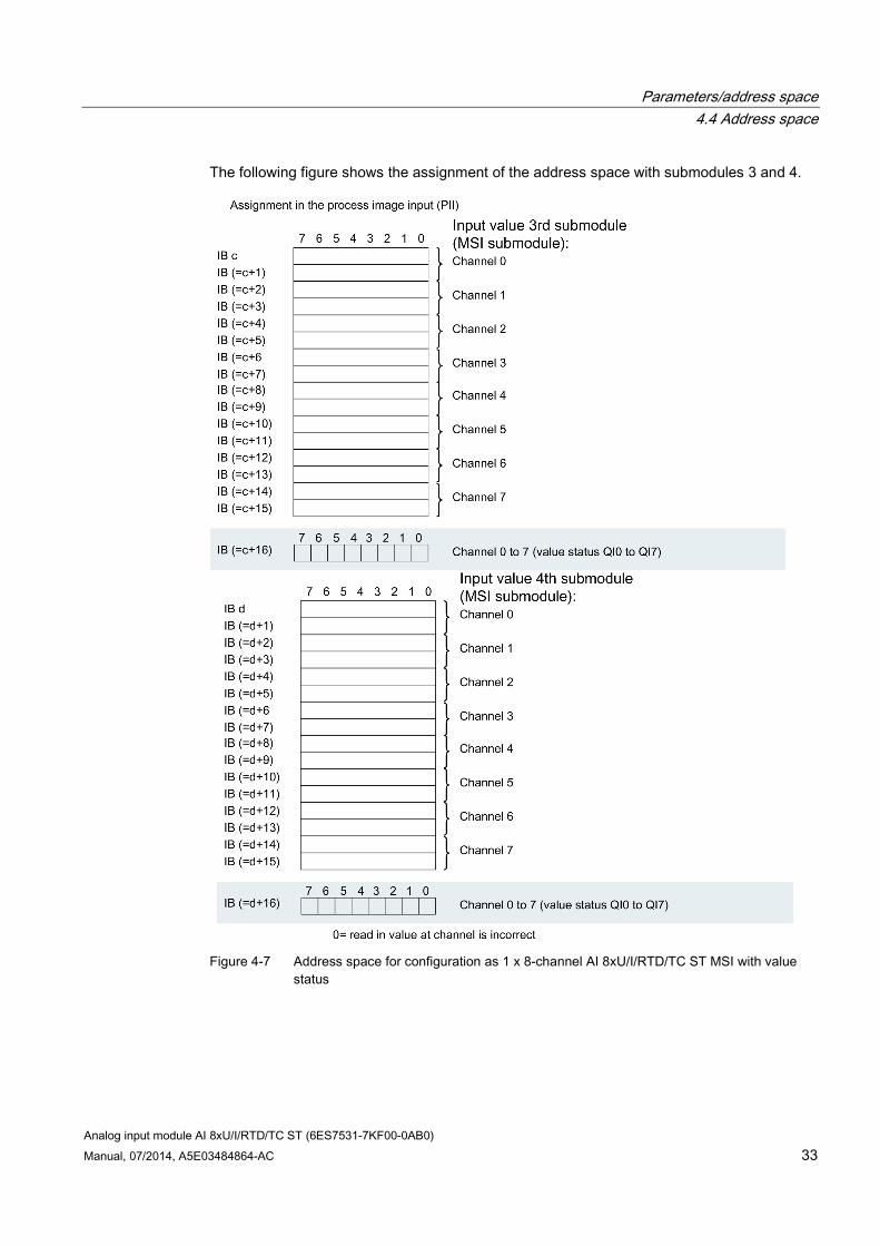
The following figure shows the assignment of the address space with submodules 3 and 4.
Figure 4-7 Address space for configuration as 1 x 8-channel AI 8xU/I/RTD/TC ST MSI with value
status
Analog input module AI 8xU/I/RTD/TC ST (6ES7531-7KF00-0AB0) 34 Manual, 07/2014, A5E03484864-AC
Interrupts/diagnostics alarms 5 5.1 Status and error displays
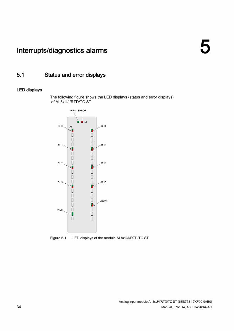
LED displays The following figure shows the LED displays (status and error displays) of AI 8xU/I/RTD/TC ST.
Figure 5-1 LED displays of the module AI 8xU/I/RTD/TC ST
Interrupts/diagnostics alarms 5.1 Status and error displays
Analog input module AI 8xU/I/RTD/TC ST (6ES7531-7KF00-0AB0) Manual, 07/2014, A5E03484864-AC 35
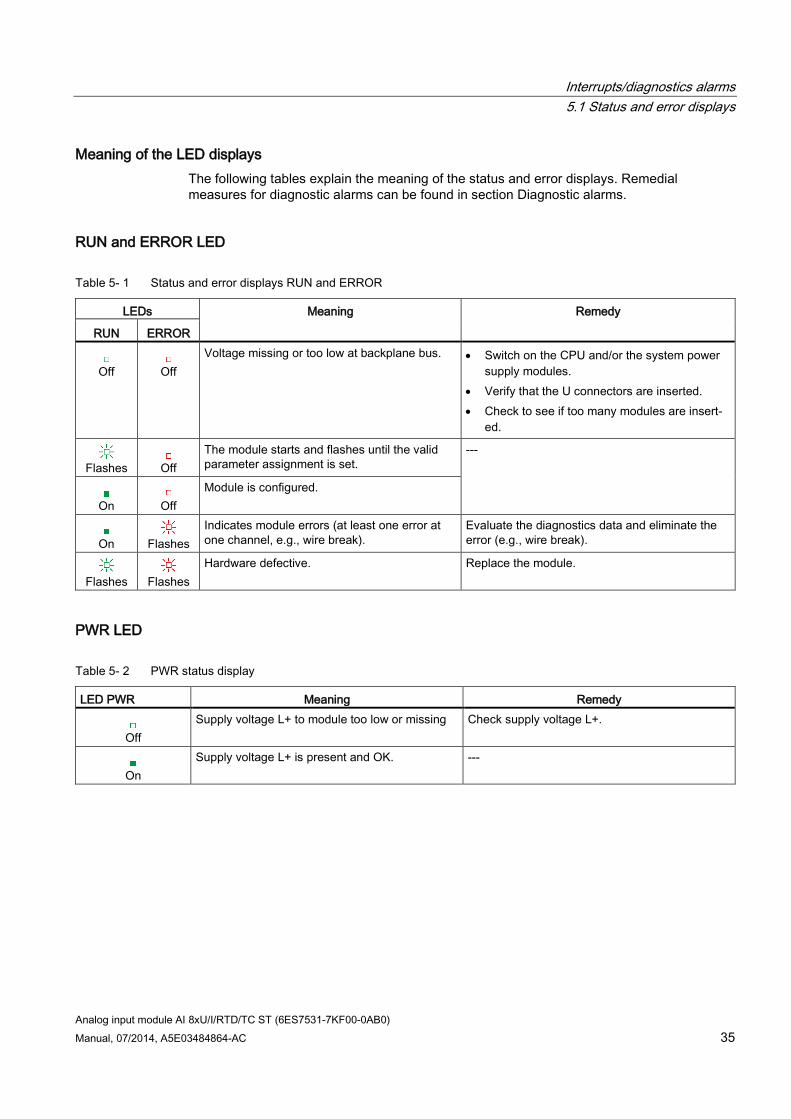
Meaning of the LED displays The following tables explain the meaning of the status and error displays. Remedial measures for diagnostic alarms can be found in section Diagnostic alarms.
RUN and ERROR LED
Table 5- 1 Status and error displays RUN and ERROR
LEDs Meaning Remedy
RUN ERROR
Off
Off Voltage missing or too low at backplane bus. • Switch on the CPU and/or the system power
supply modules. • Verify that the U connectors are inserted. • Check to see if too many modules are insert-
ed.
Flashes
Off
The module starts and flashes until the valid parameter assignment is set.
---
On
Off
Module is configured.
On
Flashes
Indicates module errors (at least one error at one channel, e.g., wire break).
Evaluate the diagnostics data and eliminate the error (e.g., wire break).
Flashes
Flashes
Hardware defective. Replace the module.
PWR LED
Table 5- 2 PWR status display
LED PWR Meaning Remedy
Off Supply voltage L+ to module too low or missing Check supply voltage L+.
On
Supply voltage L+ is present and OK. ---
Interrupts/diagnostics alarms 5.1 Status and error displays
Analog input module AI 8xU/I/RTD/TC ST (6ES7531-7KF00-0AB0) 36 Manual, 07/2014, A5E03484864-AC
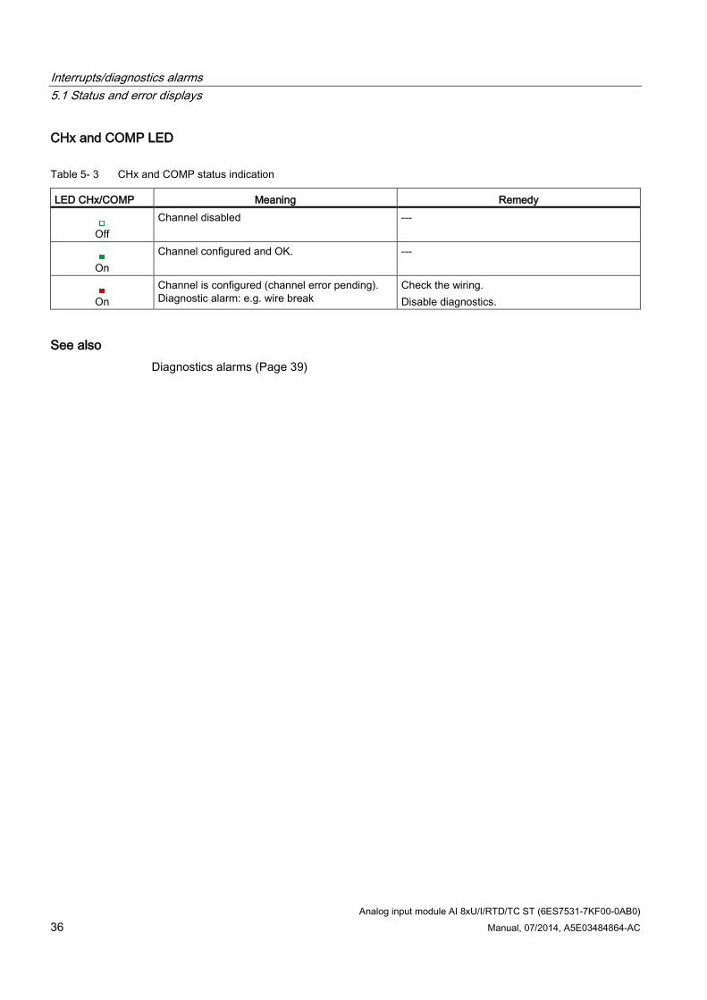
CHx and COMP LED
Table 5- 3 CHx and COMP status indication
LED CHx/COMP Meaning Remedy
Off Channel disabled ---
On
Channel configured and OK. ---
On
Channel is configured (channel error pending). Diagnostic alarm: e.g. wire break
Check the wiring. Disable diagnostics.
See also Diagnostics alarms (Page 39)
Interrupts/diagnostics alarms 5.2 Interrupts
Analog input module AI 8xU/I/RTD/TC ST (6ES7531-7KF00-0AB0) Manual, 07/2014, A5E03484864-AC 37
5.2 Interrupts Analog input module AI 8xU/I/RTD/TC ST supports the following diagnostic and hardware interrupts.
Diagnostic interrupt The module generates a diagnostic interrupt at the following events:
Missing supply voltage L+
Wire break
Overflow
Underflow
Common mode error
Reference channel error
Hardware interrupt The module generates a hardware interrupt at the following events:
Low limit violated 1
High limit violated 1
Low limit violated 2
Violation of high limit 2
For detailed information on the error event, refer to the hardware interrupt organization block with the "RALRM" instruction (read additional interrupt info) and to the STEP 7 online help.
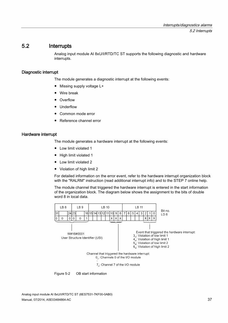
The module channel that triggered the hardware interrupt is entered in the start information of the organization block. The diagram below shows the assignment to the bits of double word 8 in local data.
Figure 5-2 OB start information
Interrupts/diagnostics alarms 5.2 Interrupts
Analog input module AI 8xU/I/RTD/TC ST (6ES7531-7KF00-0AB0) 38 Manual, 07/2014, A5E03484864-AC
Reaction when reaching limits 1 and 2 at the same time If the two high limits 1 and 2 are reached at the same time, the module always signals the hardware interrupt for high limit 1 first. The configured value for high limit 2 is irrelevant. After processing the hardware interrupt for high limit 1, the module triggers the hardware interrupt for high limit 2.
The module has the same reaction when the low limits are reached at the same time. If the two low limits 1 and 2 are reached at the same time, the module always signals the hardware interrupt for low limit 1 first. After processing the hardware interrupt for low limit 1, the module triggers the hardware interrupt for low limit 2.
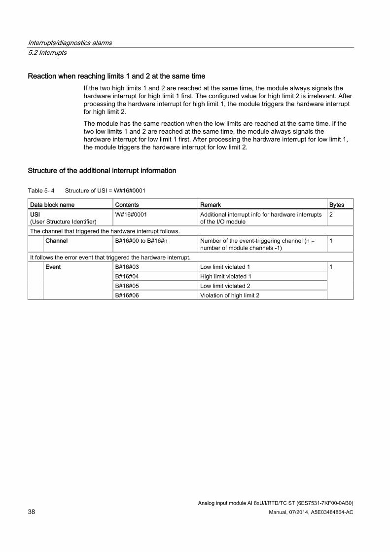
Structure of the additional interrupt information
Table 5- 4 Structure of USI = W#16#0001
Data block name Contents Remark Bytes USI (User Structure Identifier)
W#16#0001 Additional interrupt info for hardware interrupts of the I/O module
2
The channel that triggered the hardware interrupt follows. Channel B#16#00 to B#16#n Number of the event-triggering channel (n =
number of module channels -1) 1
It follows the error event that triggered the hardware interrupt. Event B#16#03 Low limit violated 1 1
B#16#04 High limit violated 1 B#16#05 Low limit violated 2 B#16#06 Violation of high limit 2
Interrupts/diagnostics alarms 5.3 Diagnostics alarms
Analog input module AI 8xU/I/RTD/TC ST (6ES7531-7KF00-0AB0) Manual, 07/2014, A5E03484864-AC 39
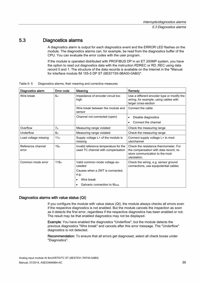
5.3 Diagnostics alarms A diagnostics alarm is output for each diagnostics event and the ERROR LED flashes on the module. The diagnostics alarms can, for example, be read from the diagnostics buffer of the CPU. You can evaluate the error codes with the user program.
If the module is operated distributed with PROFIBUS DP in an ET 200MP system, you have the option to read out diagnostics data with the instruction RDREC or RD_REC using data record 0 and 1. The structure of the data records is available on the Internet in the "Manual for interface module IM 155-5 DP ST (6ES7155-5BA00-0AB0)".
Table 5- 5 Diagnostics alarms, their meaning and corrective measures
Diagnostics alarm Error code Meaning Remedy Wire break 6H Impedance of encoder circuit too
high Use a different encoder type or modify the wiring, for example, using cables with larger cross-section
Wire break between the module and sensor
Connect the cable
Channel not connected (open) • Disable diagnostics • Connect the channel
Overflow 7H Measuring range violated Check the measuring range Underflow 8H Measuring range violated Check the measuring range Load voltage missing 11H Supply voltage L+ of the module is
missing Connect supply voltage L+ to mod-ule/channel
Reference channel error
15H Invalid reference temperature for the used TC channel with compensation
Check the resistance thermometer. For the compensation with data record, re-store communication to the mod-ule/station.
Common mode error 118H Valid common mode voltage ex-ceeded Causes when a 2WT is connected, e.g.: • Wire break • Galvanic connection to MANA
Check the wiring, e.g. sensor ground connections, use equipotential cables
Diagnostics alarms with value status (QI) If you configure the module with value status (QI), the module always checks all errors even if the respective diagnostics is not enabled. But the module cancels the inspection as soon as it detects the first error, regardless if the respective diagnostics has been enabled or not. The result may be that enabled diagnostics may not be displayed.
Example: You have enabled the diagnostics "Underflow", but the module detects the previous diagnostics "Wire break" and cancels after this error message. The "Underflow" diagnostics is not detected.
Recommendation: To ensure that all errors get diagnosed, select all check boxes under "Diagnostics".
Analog input module AI 8xU/I/RTD/TC ST (6ES7531-7KF00-0AB0) 40 Manual, 07/2014, A5E03484864-AC
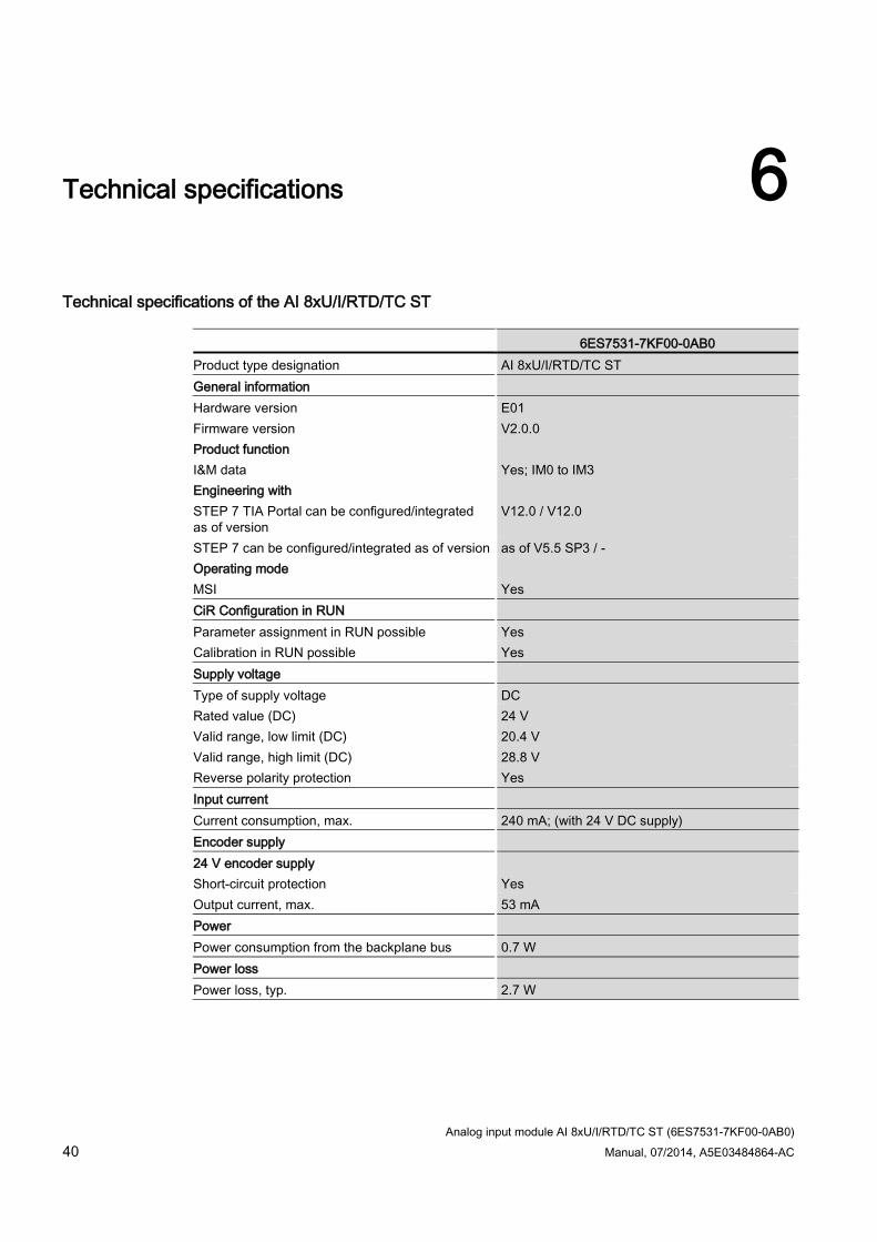
Technical specifications 6
Technical specifications of the AI 8xU/I/RTD/TC ST
6ES7531-7KF00-0AB0 Product type designation AI 8xU/I/RTD/TC ST General information Hardware version E01 Firmware version V2.0.0 Product function I&M data Yes; IM0 to IM3 Engineering with STEP 7 TIA Portal can be configured/integrated as of version
V12.0 / V12.0
STEP 7 can be configured/integrated as of version as of V5.5 SP3 / - Operating mode MSI Yes CiR Configuration in RUN Parameter assignment in RUN possible Yes Calibration in RUN possible Yes Supply voltage Type of supply voltage DC Rated value (DC) 24 V Valid range, low limit (DC) 20.4 V Valid range, high limit (DC) 28.8 V Reverse polarity protection Yes Input current Current consumption, max. 240 mA; (with 24 V DC supply) Encoder supply 24 V encoder supply Short-circuit protection Yes Output current, max. 53 mA Power Power consumption from the backplane bus 0.7 W Power loss Power loss, typ. 2.7 W
Technical specifications
Analog input module AI 8xU/I/RTD/TC ST (6ES7531-7KF00-0AB0) Manual, 07/2014, A5E03484864-AC 41
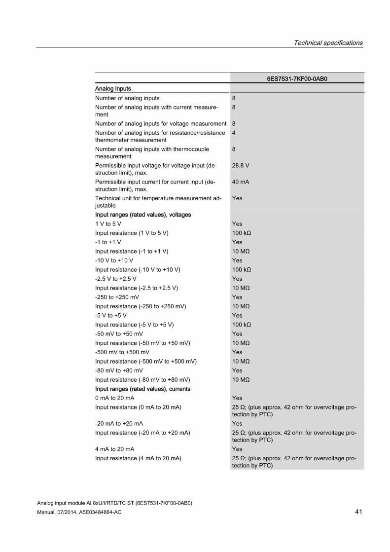
6ES7531-7KF00-0AB0 Analog inputs Number of analog inputs 8 Number of analog inputs with current measure-ment
8
Number of analog inputs for voltage measurement 8 Number of analog inputs for resistance/resistance thermometer measurement
4
Number of analog inputs with thermocouple measurement
8
Permissible input voltage for voltage input (de-struction limit), max.
28.8 V
Permissible input current for current input (de-struction limit), max.
40 mA
Technical unit for temperature measurement ad-justable
Yes
Input ranges (rated values), voltages 1 V to 5 V Yes Input resistance (1 V to 5 V) 100 kΩ -1 to +1 V Yes Input resistance (-1 to +1 V) 10 MΩ -10 V to +10 V Yes Input resistance (-10 V to +10 V) 100 kΩ -2.5 V to +2.5 V Yes Input resistance (-2.5 to +2.5 V) 10 MΩ -250 to +250 mV Yes Input resistance (-250 to +250 mV) 10 MΩ -5 V to +5 V Yes Input resistance (-5 V to +5 V) 100 kΩ -50 mV to +50 mV Yes Input resistance (-50 mV to +50 mV) 10 MΩ -500 mV to +500 mV Yes Input resistance (-500 mV to +500 mV) 10 MΩ -80 mV to +80 mV Yes Input resistance (-80 mV to +80 mV) 10 MΩ Input ranges (rated values), currents 0 mA to 20 mA Yes Input resistance (0 mA to 20 mA) 25 Ω; (plus approx. 42 ohm for overvoltage pro-
tection by PTC) -20 mA to +20 mA Yes Input resistance (-20 mA to +20 mA) 25 Ω; (plus approx. 42 ohm for overvoltage pro-
tection by PTC) 4 mA to 20 mA Yes Input resistance (4 mA to 20 mA) 25 Ω; (plus approx. 42 ohm for overvoltage pro-
tection by PTC)
Technical specifications
Analog input module AI 8xU/I/RTD/TC ST (6ES7531-7KF00-0AB0) 42 Manual, 07/2014, A5E03484864-AC
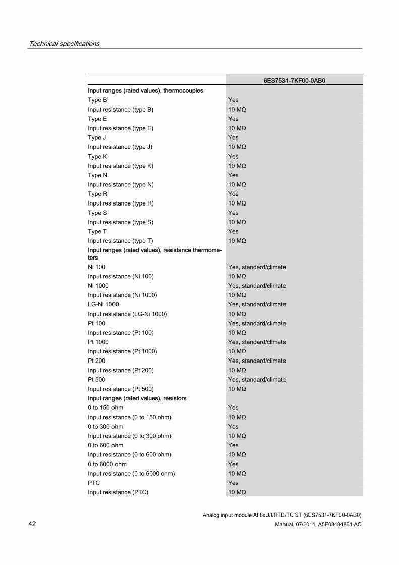
6ES7531-7KF00-0AB0 Input ranges (rated values), thermocouples Type B Yes Input resistance (type B) 10 MΩ Type E Yes Input resistance (type E) 10 MΩ Type J Yes Input resistance (type J) 10 MΩ Type K Yes Input resistance (type K) 10 MΩ Type N Yes Input resistance (type N) 10 MΩ Type R Yes Input resistance (type R) 10 MΩ Type S Yes Input resistance (type S) 10 MΩ Type T Yes Input resistance (type T) 10 MΩ Input ranges (rated values), resistance thermome-ters
Ni 100 Yes, standard/climate Input resistance (Ni 100) 10 MΩ Ni 1000 Yes, standard/climate Input resistance (Ni 1000) 10 MΩ LG-Ni 1000 Yes, standard/climate Input resistance (LG-Ni 1000) 10 MΩ Pt 100 Yes, standard/climate Input resistance (Pt 100) 10 MΩ Pt 1000 Yes, standard/climate Input resistance (Pt 1000) 10 MΩ Pt 200 Yes, standard/climate Input resistance (Pt 200) 10 MΩ Pt 500 Yes, standard/climate Input resistance (Pt 500) 10 MΩ Input ranges (rated values), resistors 0 to 150 ohm Yes Input resistance (0 to 150 ohm) 10 MΩ 0 to 300 ohm Yes Input resistance (0 to 300 ohm) 10 MΩ 0 to 600 ohm Yes Input resistance (0 to 600 ohm) 10 MΩ 0 to 6000 ohm Yes Input resistance (0 to 6000 ohm) 10 MΩ PTC Yes Input resistance (PTC) 10 MΩ
Technical specifications
Analog input module AI 8xU/I/RTD/TC ST (6ES7531-7KF00-0AB0) Manual, 07/2014, A5E03484864-AC 43
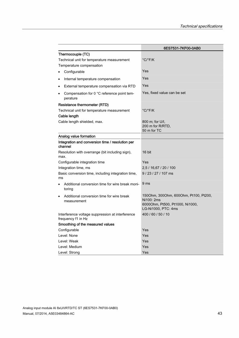
6ES7531-7KF00-0AB0 Thermocouple (TC) Technical unit for temperature measurement °C/°F/K Temperature compensation • Configurable Yes
• Internal temperature compensation Yes
• External temperature compensation via RTD Yes
• Compensation for 0 °C reference point tem-perature
Yes, fixed value can be set
Resistance thermometer (RTD) Technical unit for temperature measurement °C/°F/K Cable length Cable length shielded, max. 800 m; for U/I,
200 m for R/RTD, 50 m for TC
Analog value formation Integration and conversion time / resolution per channel
Resolution with overrange (bit including sign), max.
16 bit
Configurable integration time Yes Integration time, ms 2,5 / 16,67 / 20 / 100 Basic conversion time, including integration time, ms
9 / 23 / 27 / 107 ms
• Additional conversion time for wire break moni-toring
9 ms
• Additional conversion time for wire break measurement
150Ohm, 300Ohm, 600Ohm, Pt100, Pt200, Ni100: 2ms 6000Ohm, Pt500, Pt1000, Ni1000, LG-Ni1000, PTC: 4ms
Interference voltage suppression at interference frequency f1 in Hz
400 / 60 / 50 / 10
Smoothing of the measured values Configurable Yes Level: None Yes Level: Weak Yes Level: Medium Yes Level: Strong Yes
Technical specifications
Analog input module AI 8xU/I/RTD/TC ST (6ES7531-7KF00-0AB0) 44 Manual, 07/2014, A5E03484864-AC
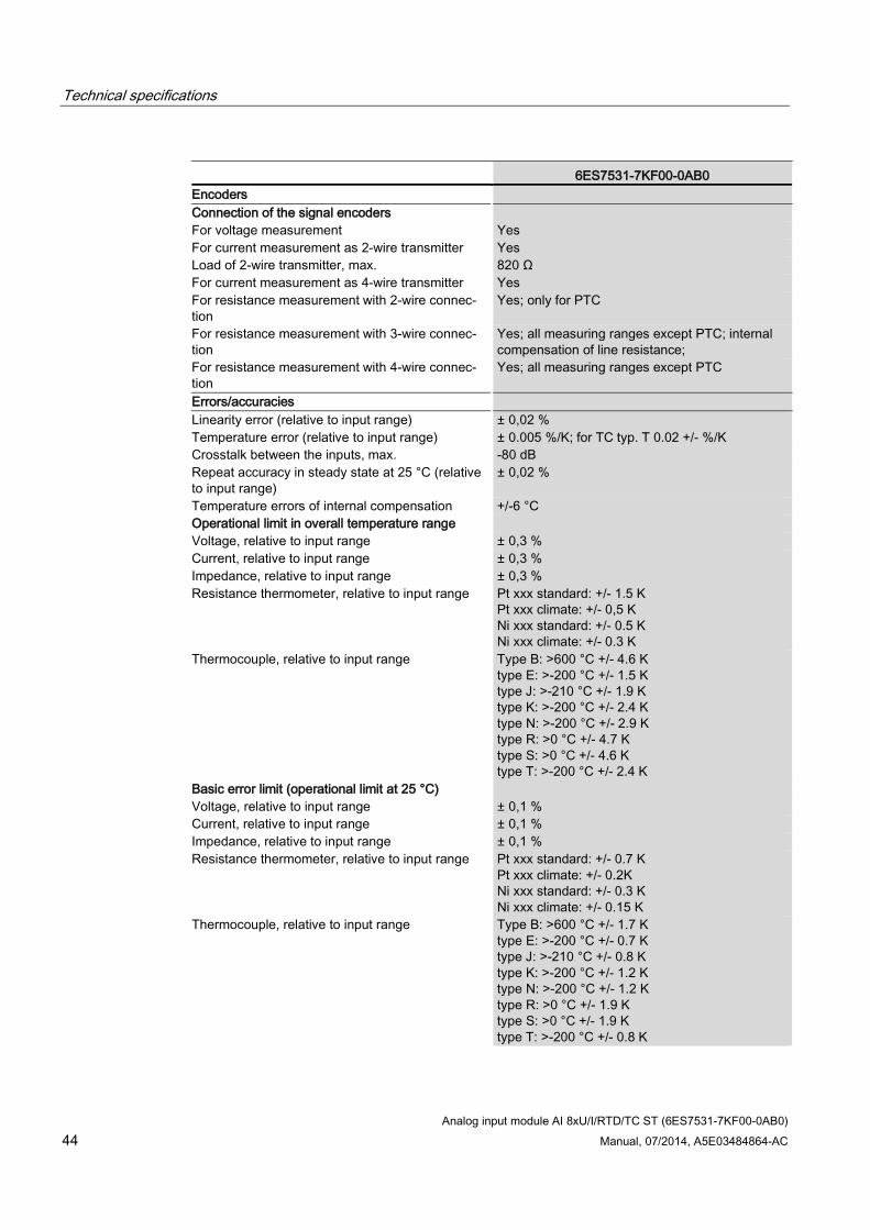
6ES7531-7KF00-0AB0 Encoders Connection of the signal encoders For voltage measurement Yes For current measurement as 2-wire transmitter Yes Load of 2-wire transmitter, max. 820 Ω For current measurement as 4-wire transmitter Yes For resistance measurement with 2-wire connec-tion
Yes; only for PTC
For resistance measurement with 3-wire connec-tion
Yes; all measuring ranges except PTC; internal compensation of line resistance;
For resistance measurement with 4-wire connec-tion
Yes; all measuring ranges except PTC
Errors/accuracies Linearity error (relative to input range) ± 0,02 % Temperature error (relative to input range) ± 0.005 %/K; for TC typ. T 0.02 +/- %/K Crosstalk between the inputs, max. -80 dB Repeat accuracy in steady state at 25 °C (relative to input range)
± 0,02 %
Temperature errors of internal compensation +/-6 °C Operational limit in overall temperature range Voltage, relative to input range ± 0,3 % Current, relative to input range ± 0,3 % Impedance, relative to input range ± 0,3 % Resistance thermometer, relative to input range Pt xxx standard: +/- 1.5 K
Pt xxx climate: +/- 0,5 K Ni xxx standard: +/- 0.5 K Ni xxx climate: +/- 0.3 K
Thermocouple, relative to input range Type B: >600 °C +/- 4.6 K type E: >-200 °C +/- 1.5 K type J: >-210 °C +/- 1.9 K type K: >-200 °C +/- 2.4 K type N: >-200 °C +/- 2.9 K type R: >0 °C +/- 4.7 K type S: >0 °C +/- 4.6 K type T: >-200 °C +/- 2.4 K
Basic error limit (operational limit at 25 °C) Voltage, relative to input range ± 0,1 % Current, relative to input range ± 0,1 % Impedance, relative to input range ± 0,1 % Resistance thermometer, relative to input range Pt xxx standard: +/- 0.7 K
Pt xxx climate: +/- 0.2K Ni xxx standard: +/- 0.3 K Ni xxx climate: +/- 0.15 K
Thermocouple, relative to input range Type B: >600 °C +/- 1.7 K type E: >-200 °C +/- 0.7 K type J: >-210 °C +/- 0.8 K type K: >-200 °C +/- 1.2 K type N: >-200 °C +/- 1.2 K type R: >0 °C +/- 1.9 K type S: >0 °C +/- 1.9 K type T: >-200 °C +/- 0.8 K
Technical specifications
Analog input module AI 8xU/I/RTD/TC ST (6ES7531-7KF00-0AB0) Manual, 07/2014, A5E03484864-AC 45
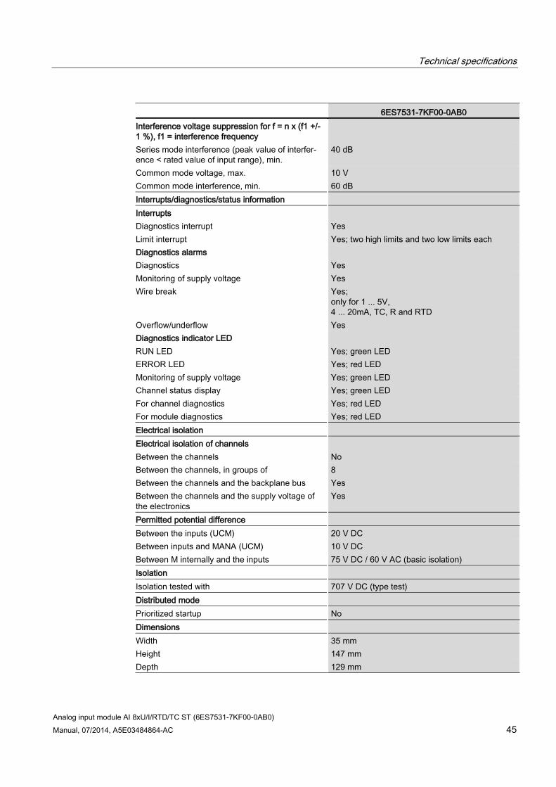
6ES7531-7KF00-0AB0 Interference voltage suppression for f = n x (f1 +/- 1 %), f1 = interference frequency
Series mode interference (peak value of interfer-ence < rated value of input range), min.
40 dB
Common mode voltage, max. 10 V Common mode interference, min. 60 dB Interrupts/diagnostics/status information Interrupts Diagnostics interrupt Yes Limit interrupt Yes; two high limits and two low limits each Diagnostics alarms Diagnostics Yes Monitoring of supply voltage Yes Wire break Yes;
only for 1 ... 5V, 4 ... 20mA, TC, R and RTD
Overflow/underflow Yes Diagnostics indicator LED RUN LED Yes; green LED ERROR LED Yes; red LED Monitoring of supply voltage Yes; green LED Channel status display Yes; green LED For channel diagnostics Yes; red LED For module diagnostics Yes; red LED Electrical isolation Electrical isolation of channels Between the channels No Between the channels, in groups of 8 Between the channels and the backplane bus Yes Between the channels and the supply voltage of the electronics
Yes
Permitted potential difference Between the inputs (UCM) 20 V DC Between inputs and MANA (UCM) 10 V DC Between M internally and the inputs 75 V DC / 60 V AC (basic isolation) Isolation Isolation tested with 707 V DC (type test) Distributed mode Prioritized startup No Dimensions Width 35 mm Height 147 mm Depth 129 mm
Technical specifications
Analog input module AI 8xU/I/RTD/TC ST (6ES7531-7KF00-0AB0) 46 Manual, 07/2014, A5E03484864-AC
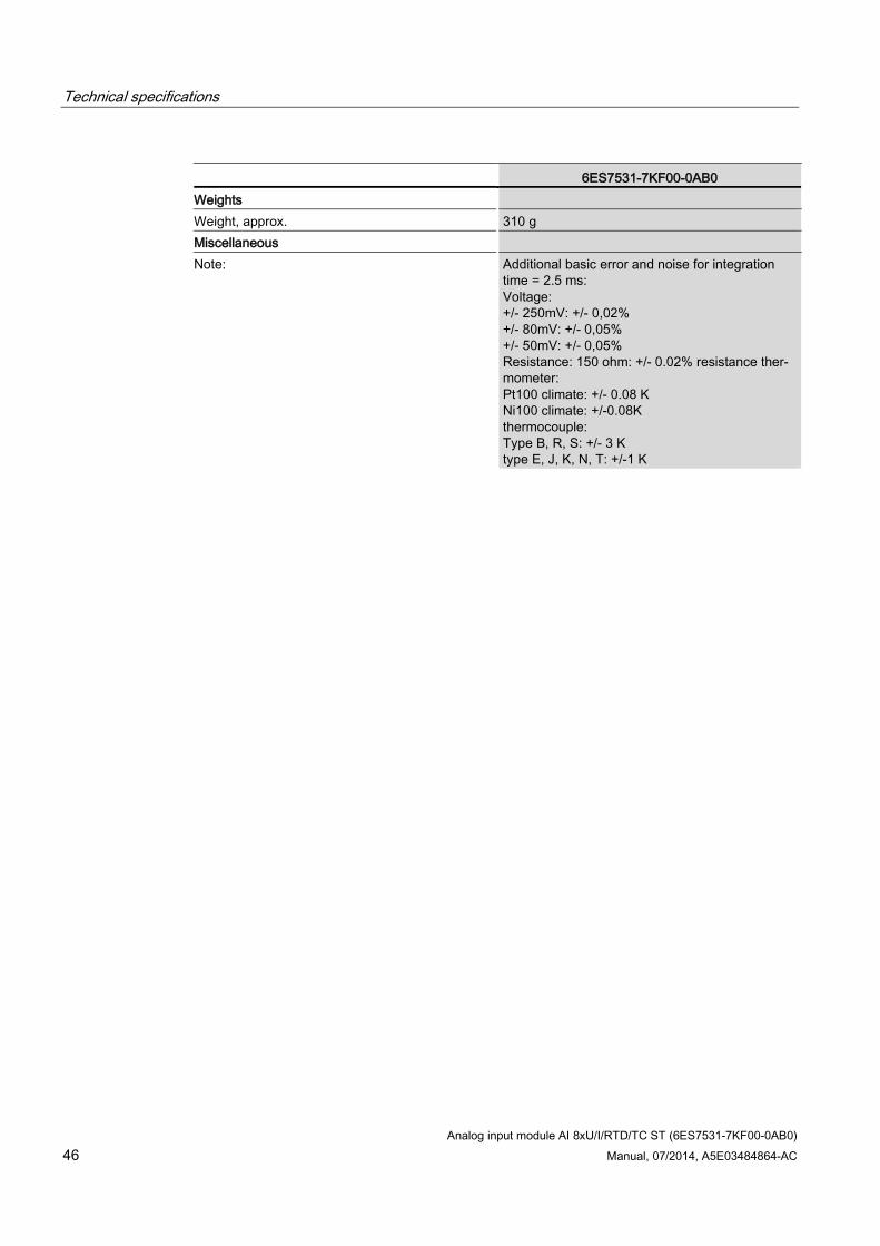
6ES7531-7KF00-0AB0 Weights Weight, approx. 310 g Miscellaneous Note: Additional basic error and noise for integration
time = 2.5 ms: Voltage: +/- 250mV: +/- 0,02% +/- 80mV: +/- 0,05% +/- 50mV: +/- 0,05% Resistance: 150 ohm: +/- 0.02% resistance ther-mometer: Pt100 climate: +/- 0.08 K Ni100 climate: +/-0.08K thermocouple: Type B, R, S: +/- 3 K type E, J, K, N, T: +/-1 K
Analog input module AI 8xU/I/RTD/TC ST (6ES7531-7KF00-0AB0) Manual, 07/2014, A5E03484864-AC 47
Dimensional drawing A
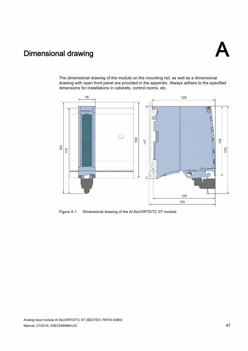
The dimensional drawing of the module on the mounting rail, as well as a dimensional drawing with open front panel are provided in the appendix. Always adhere to the specified dimensions for installations in cabinets, control rooms, etc.
Figure A-1 Dimensional drawing of the AI 8xU/I/RTD/TC ST module
Dimensional drawing
Analog input module AI 8xU/I/RTD/TC ST (6ES7531-7KF00-0AB0) 48 Manual, 07/2014, A5E03484864-AC
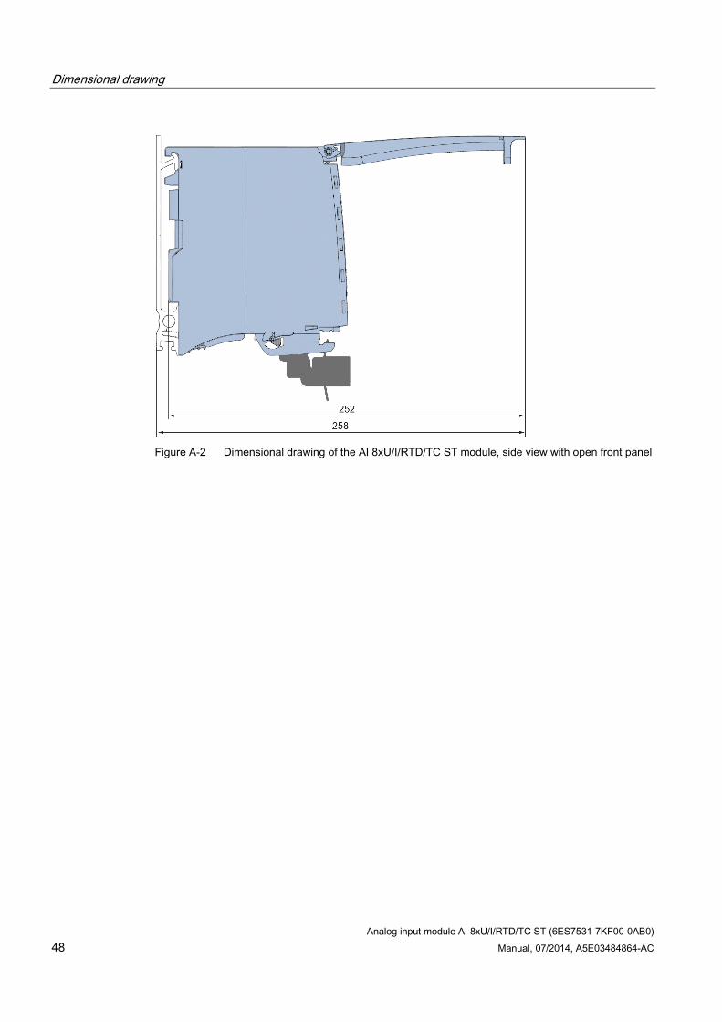
Figure A-2 Dimensional drawing of the AI 8xU/I/RTD/TC ST module, side view with open front panel
Analog input module AI 8xU/I/RTD/TC ST (6ES7531-7KF00-0AB0) Manual, 07/2014, A5E03484864-AC 49
Parameter data records B B.1 Parameter assignment and structure of the parameter data records
The data records of the module have an identical structure, regardless of whether you configure the module with PROFIBUS DP or PROFINET IO.
Dependencies for configuration with GSD file When configuring the module with a GSD file, remember that the settings of some parameters are dependent on each other. The parameters are only checked for plausibility by the module after the transfer to the module.
The following table lists the parameters that depend on one another.
Table B- 1 Dependencies of parameters for configuration with GSD file
Device-specific parameters (GSD file) Dependent parameters Current limit for wire break Only for measuring type current with measuring range 4 mA to 20 mA. Wire break Only for measuring type resistance, thermistor RTD, thermocouple TC,
voltage with measuring range 1V to 5 V and current with measuring range 4 mA to 20 mA.
Common mode error Only for measuring type voltage, current and thermocouple TC. Reference channel error Only for measuring type thermocouple TC. Measuring type resistance (4-wire connection, 3-wire connection)
Only for measuring range 150 Ω, 300 Ω, 600 Ω and 6000 Ω.
Measuring type resistance (4-wire connection, 3-wire connection, 2-wire connection)
Configurable for even channels (0, 2, 4 and 6) only. The following odd channel (1, 3, 5, 7) must be deactivated. Measuring type thermistor RTD (4-wire connec-
tion, 3-wire connection) Hardware interrupt limits Only if hardware interrupts are enabled. Fixed reference temperature Only if the value Fixed reference temperature is configured at parameter
Reference junction for TC. Temperature unit Kelvin (K) Only for measuring type thermistor RTD and for thermocouple TC.
Parameter assignment in the user program The module parameters can be assigned in RUN (for example, measuring ranges of selected channels can be edited in RUN without having an effect on the other channels).
Parameter data records B.1 Parameter assignment and structure of the parameter data records
Analog input module AI 8xU/I/RTD/TC ST (6ES7531-7KF00-0AB0) 50 Manual, 07/2014, A5E03484864-AC
Parameter assignment in RUN Instruction WRREC is used to transfer the parameters by means of data records 0 to 7 and 8. The parameters set in STEP 7 do not change in the CPU, which means the parameters set in STEP 7 are still valid after a restart.
The parameters are only checked for plausibility by the module after the transfer to the module.
Output parameter STATUS The module ignores errors that occurred during the transfer of parameters with the WRREC instruction and continues operation with the previous parameter assignment. However, a corresponding error code is written to the STATUS output parameter.
The description of the WRREC instruction and the error codes is available in the STEP 7 online help.
Operation of the module behind a PROFIBUS DP interface module If the module is operated behind a PROFIBUS DP interface module, the parameter data records 0 and 1 are not read back. You get the diagnostics data records 0 and 1 for the read back parameter data records 0 and 1. You can find more information in the Interrupts section of the PROFIBUS DP interface module device manual on the Internet (http://support.automation.siemens.com/WW/view/en/78324181).
Parameter data records B.1 Parameter assignment and structure of the parameter data records
Analog input module AI 8xU/I/RTD/TC ST (6ES7531-7KF00-0AB0) Manual, 07/2014, A5E03484864-AC 51
Assignment of data record and channel The parameters in data records 0 to 7 and in data record 8 are available for 1x 8-channel configuration and are assigned as follows:
Data record 0 for channel 0
Data record 1 for channel 1
…
Data record 6 for channel 6
Data record 7 for channel 7
Data record 8 for the reference channel (COMP)
For configuration 8 x 1-channel, the module has 8 submodules with one channel each and one submodule for the reference channel. The parameters for the channel are available in data record 0 and are assigned as follows:
Data record 0 for channel 0 (submodule 1)
Data record 0 for channel 1 (submodule 2)
…
Data record 0 for channel 6 (submodule 7)
Data record 0 for channel 7 (submodule 8)
Data record 0 for the reference channel (COMP) (submodule 9)
Address the respective submodule for data record transfer.
Data record structure The example in the following figure shows the structure of data record 0 for channel 0. The structure of channels 1 to 7 is identical. The values in byte 0 and byte 1 are fixed and may not be changed.
Parameter data records B.1 Parameter assignment and structure of the parameter data records
Analog input module AI 8xU/I/RTD/TC ST (6ES7531-7KF00-0AB0) 52 Manual, 07/2014, A5E03484864-AC
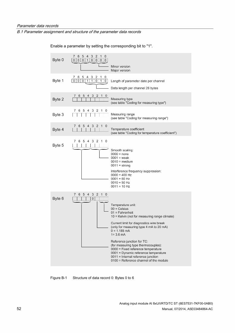
Enable a parameter by setting the corresponding bit to "1".
Figure B-1 Structure of data record 0: Bytes 0 to 6
Parameter data records B.1 Parameter assignment and structure of the parameter data records
Analog input module AI 8xU/I/RTD/TC ST (6ES7531-7KF00-0AB0) Manual, 07/2014, A5E03484864-AC 53
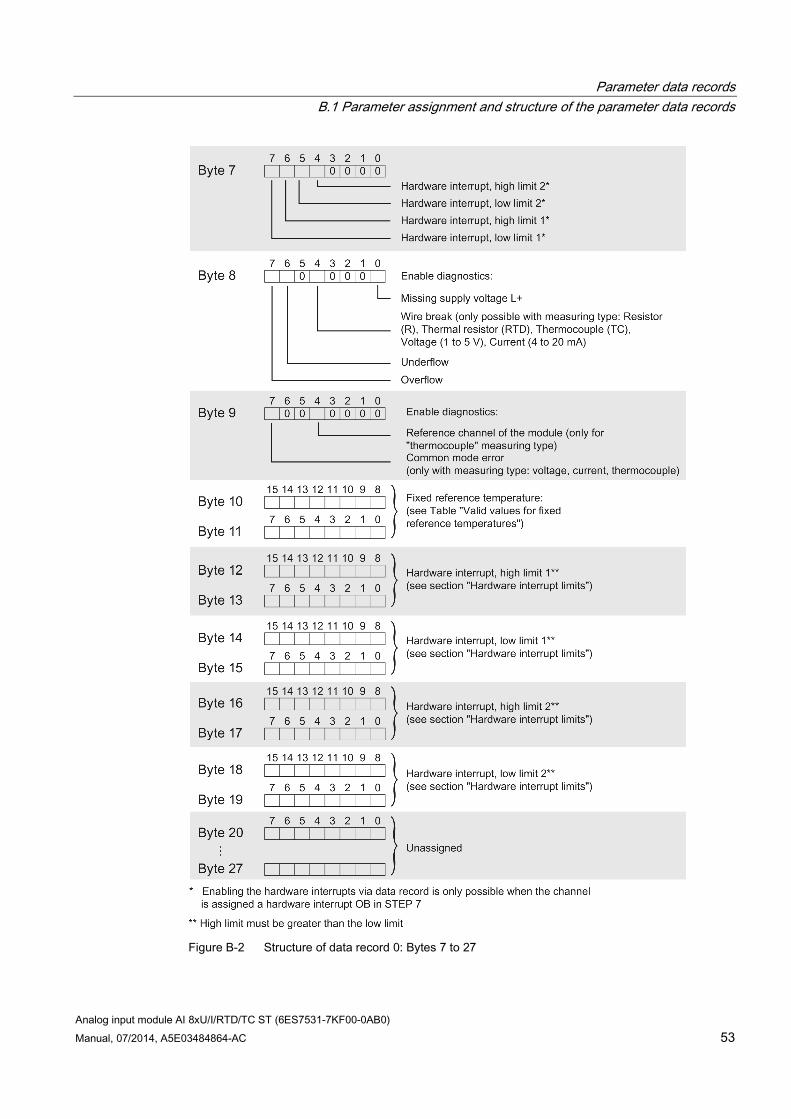
Figure B-2 Structure of data record 0: Bytes 7 to 27
Parameter data records B.1 Parameter assignment and structure of the parameter data records
Analog input module AI 8xU/I/RTD/TC ST (6ES7531-7KF00-0AB0) 54 Manual, 07/2014, A5E03484864-AC
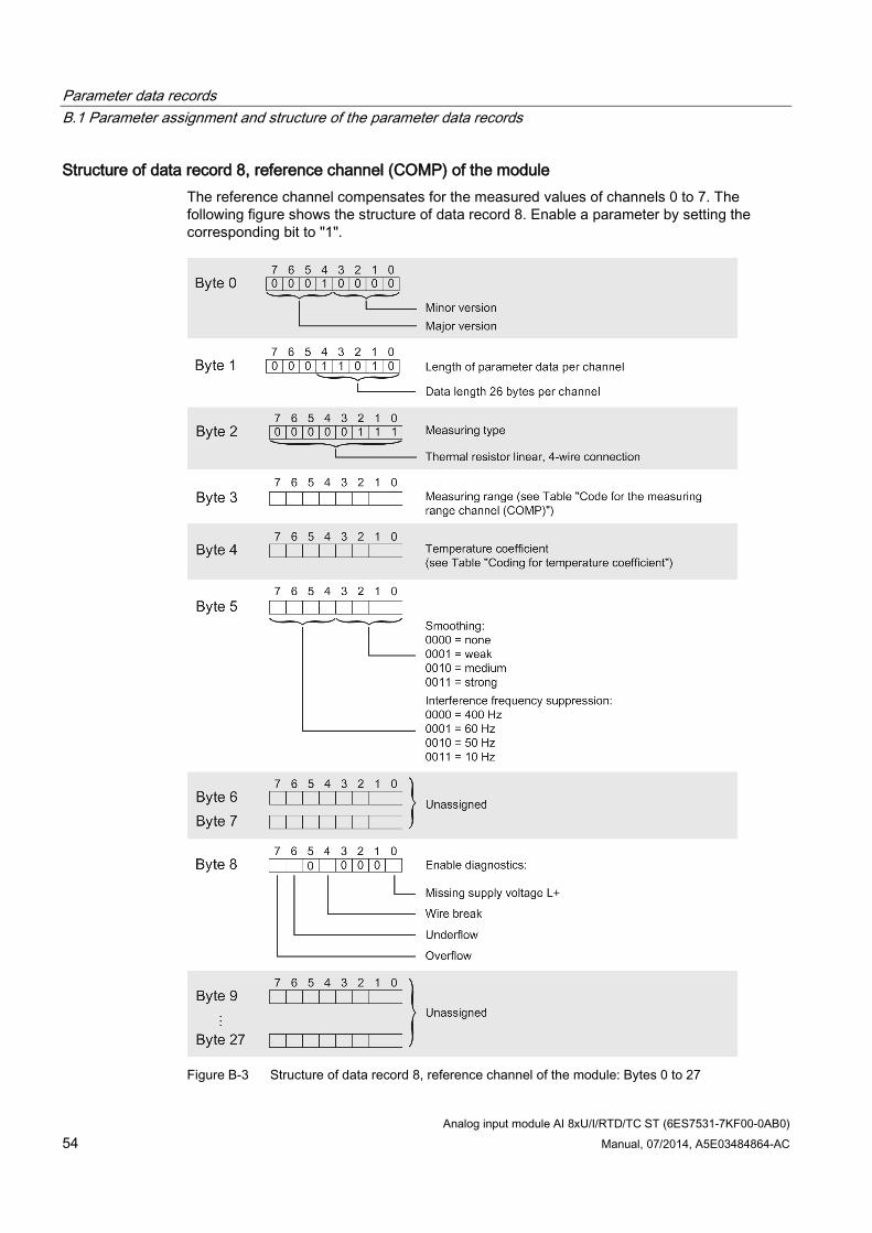
Structure of data record 8, reference channel (COMP) of the module The reference channel compensates for the measured values of channels 0 to 7. The following figure shows the structure of data record 8. Enable a parameter by setting the corresponding bit to "1".
Figure B-3 Structure of data record 8, reference channel of the module: Bytes 0 to 27
Parameter data records B.1 Parameter assignment and structure of the parameter data records
Analog input module AI 8xU/I/RTD/TC ST (6ES7531-7KF00-0AB0) Manual, 07/2014, A5E03484864-AC 55
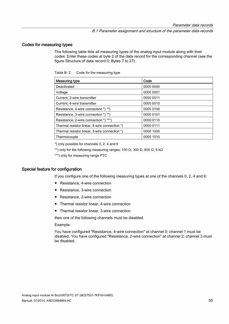
Codes for measuring types The following table lists all measuring types of the analog input module along with their codes. Enter these codes at byte 2 of the data record for the corresponding channel (see the figure Structure of data record 0: Bytes 7 to 27).
Table B- 2 Code for the measuring type
Measuring type Code Deactivated 0000 0000 Voltage 0000 0001 Current, 2-wire transmitter 0000 0011 Current, 4-wire transmitter 0000 0010 Resistance, 4-wire connection *) **) 0000 0100 Resistance, 3-wire connection *) **) 0000 0101 Resistance, 2-wire connection *) ***) 0000 0110 Thermal resistor linear, 4-wire connection *) 0000 0111 Thermal resistor linear, 3-wire connection *) 0000 1000 Thermocouple 0000 1010 *) only possible for channels 0, 2, 4 and 6
**) only for the following measuring ranges: 150 Ω, 300 Ω, 600 Ω, 6 kΩ ***) only for measuring range PTC
Special feature for configuration If you configure one of the following measuring types at one of the channels 0, 2, 4 and 6:
Resistance, 4-wire connection
Resistance, 3-wire connection
Resistance, 2-wire connection
Thermal resistor linear, 4-wire connection
Thermal resistor linear, 3-wire connection
then one of the following channels must be disabled.
Example:
You have configured "Resistance, 4-wire connection" at channel 0; channel 1 must be disabled. You have configured "Resistance, 2-wire connection" at channel 2; channel 3 must be disabled.
Parameter data records B.1 Parameter assignment and structure of the parameter data records
Analog input module AI 8xU/I/RTD/TC ST (6ES7531-7KF00-0AB0) 56 Manual, 07/2014, A5E03484864-AC
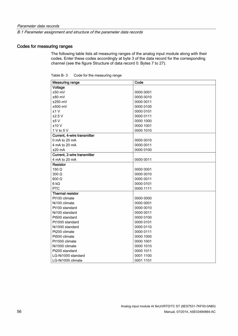
Codes for measuring ranges The following table lists all measuring ranges of the analog input module along with their codes. Enter these codes accordingly at byte 3 of the data record for the corresponding channel (see the figure Structure of data record 0: Bytes 7 to 27).
Table B- 3 Code for the measuring range
Measuring range Code Voltage ±50 mV ±80 mV ±250 mV ±500 mV ±1 V ±2.5 V ±5 V ±10 V 1 V to 5 V
0000 0001 0000 0010 0000 0011 0000 0100 0000 0101 0000 0111 0000 1000 0000 1001 0000 1010
Current, 4-wire transmitter 0 mA to 20 mA 4 mA to 20 mA ±20 mA
0000 0010 0000 0011 0000 0100
Current, 2-wire transmitter 4 mA to 20 mA
0000 0011
Resistor 150 Ω 300 Ω 600 Ω 6 kΩ PTC
0000 0001 0000 0010 0000 0011 0000 0101 0000 1111
Thermal resistor Pt100 climate Ni100 climate Pt100 standard Ni100 standard Pt500 standard Pt1000 standard Ni1000 standard Pt200 climate Pt500 climate Pt1000 climate Ni1000 climate Pt200 standard LG-Ni1000 standard LG-Ni1000 climate
0000 0000 0000 0001 0000 0010 0000 0011 0000 0100 0000 0101 0000 0110 0000 0111 0000 1000 0000 1001 0000 1010 0000 1011 0001 1100 0001 1101
Parameter data records B.1 Parameter assignment and structure of the parameter data records
Analog input module AI 8xU/I/RTD/TC ST (6ES7531-7KF00-0AB0) Manual, 07/2014, A5E03484864-AC 57
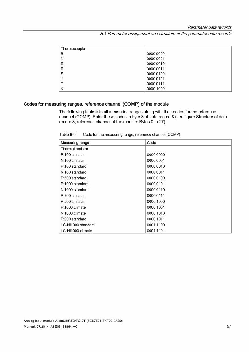
Thermocouple B N E R S J T K
0000 0000 0000 0001 0000 0010 0000 0011 0000 0100 0000 0101 0000 0111 0000 1000
Codes for measuring ranges, reference channel (COMP) of the module The following table lists all measuring ranges along with their codes for the reference channel (COMP). Enter these codes in byte 3 of data record 8 (see figure Structure of data record 8, reference channel of the module: Bytes 0 to 27).
Table B- 4 Code for the measuring range, reference channel (COMP)
Measuring range Code Thermal resistor Pt100 climate Ni100 climate Pt100 standard Ni100 standard Pt500 standard Pt1000 standard Ni1000 standard Pt200 climate Pt500 climate Pt1000 climate Ni1000 climate Pt200 standard LG-Ni1000 standard LG-Ni1000 climate
0000 0000 0000 0001 0000 0010 0000 0011 0000 0100 0000 0101 0000 0110 0000 0111 0000 1000 0000 1001 0000 1010 0000 1011 0001 1100 0001 1101
Parameter data records B.1 Parameter assignment and structure of the parameter data records
Analog input module AI 8xU/I/RTD/TC ST (6ES7531-7KF00-0AB0) 58 Manual, 07/2014, A5E03484864-AC
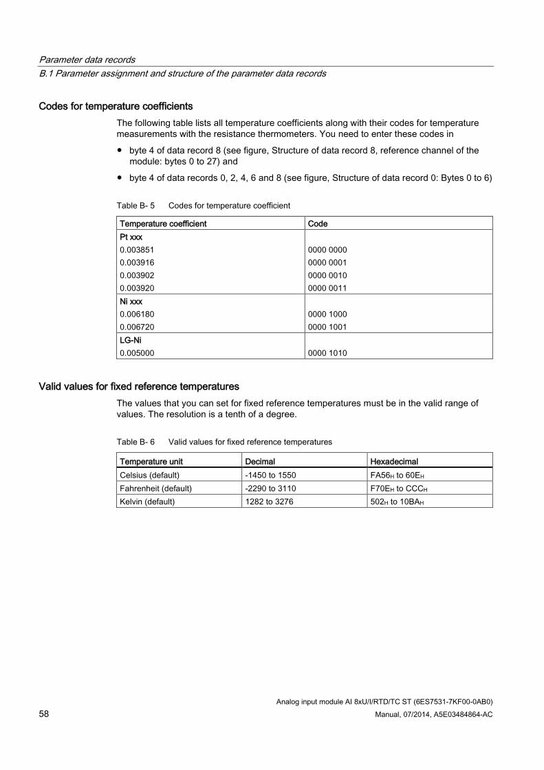
Codes for temperature coefficients The following table lists all temperature coefficients along with their codes for temperature measurements with the resistance thermometers. You need to enter these codes in
byte 4 of data record 8 (see figure, Structure of data record 8, reference channel of the module: bytes 0 to 27) and
byte 4 of data records 0, 2, 4, 6 and 8 (see figure, Structure of data record 0: Bytes 0 to 6)
Table B- 5 Codes for temperature coefficient
Temperature coefficient Code Pt xxx 0.003851 0.003916 0.003902 0.003920
0000 0000 0000 0001 0000 0010 0000 0011
Ni xxx 0.006180 0.006720
0000 1000 0000 1001
LG-Ni 0.005000
0000 1010
Valid values for fixed reference temperatures The values that you can set for fixed reference temperatures must be in the valid range of values. The resolution is a tenth of a degree.
Table B- 6 Valid values for fixed reference temperatures
Temperature unit Decimal Hexadecimal Celsius (default) -1450 to 1550 FA56H to 60EH Fahrenheit (default) -2290 to 3110 F70EH to CCCH Kelvin (default) 1282 to 3276 502H to 10BAH
Parameter data records B.1 Parameter assignment and structure of the parameter data records
Analog input module AI 8xU/I/RTD/TC ST (6ES7531-7KF00-0AB0) Manual, 07/2014, A5E03484864-AC 59
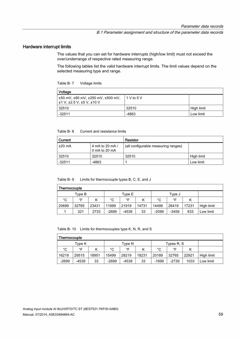
Hardware interrupt limits The values that you can set for hardware interrupts (high/low limit) must not exceed the over/underrange of respective rated measuring range.
The following tables list the valid hardware interrupt limits. The limit values depend on the selected measuring type and range.
Table B- 7 Voltage limits
Voltage ±50 mV, ±80 mV, ±250 mV, ±500 mV, ±1 V, ±2.5 V, ±5 V, ±10 V
1 V to 5 V
32510 32510 High limit -32511 -4863 Low limit
Table B- 8 Current and resistance limits
Current Resistor ±20 mA 4 mA to 20 mA /
0 mA to 20 mA (all configurable measuring ranges)
32510 32510 32510 High limit -32511 -4863 1 Low limit
Table B- 9 Limits for thermocouple types B, C, E, and J
Thermocouple Type B Type E Type J
°C °F K °C °F K °C °F K 20699 32765 23431 11999 21919 14731 14499 26419 17231 High limit
1 321 2733 -2699 -4539 33 -2099 -3459 633 Low limit
Table B- 10 Limits for thermocouples type K, N, R, and S
Thermocouple Type K Type N Types R, S
°C °F K °C °F K °C °F K 16219 29515 18951 15499 28219 18231 20189 32765 22921 High limit -2699 -4539 33 -2699 -4539 33 -1699 -2739 1033 Low limit
Parameter data records B.1 Parameter assignment and structure of the parameter data records
Analog input module AI 8xU/I/RTD/TC ST (6ES7531-7KF00-0AB0) 60 Manual, 07/2014, A5E03484864-AC
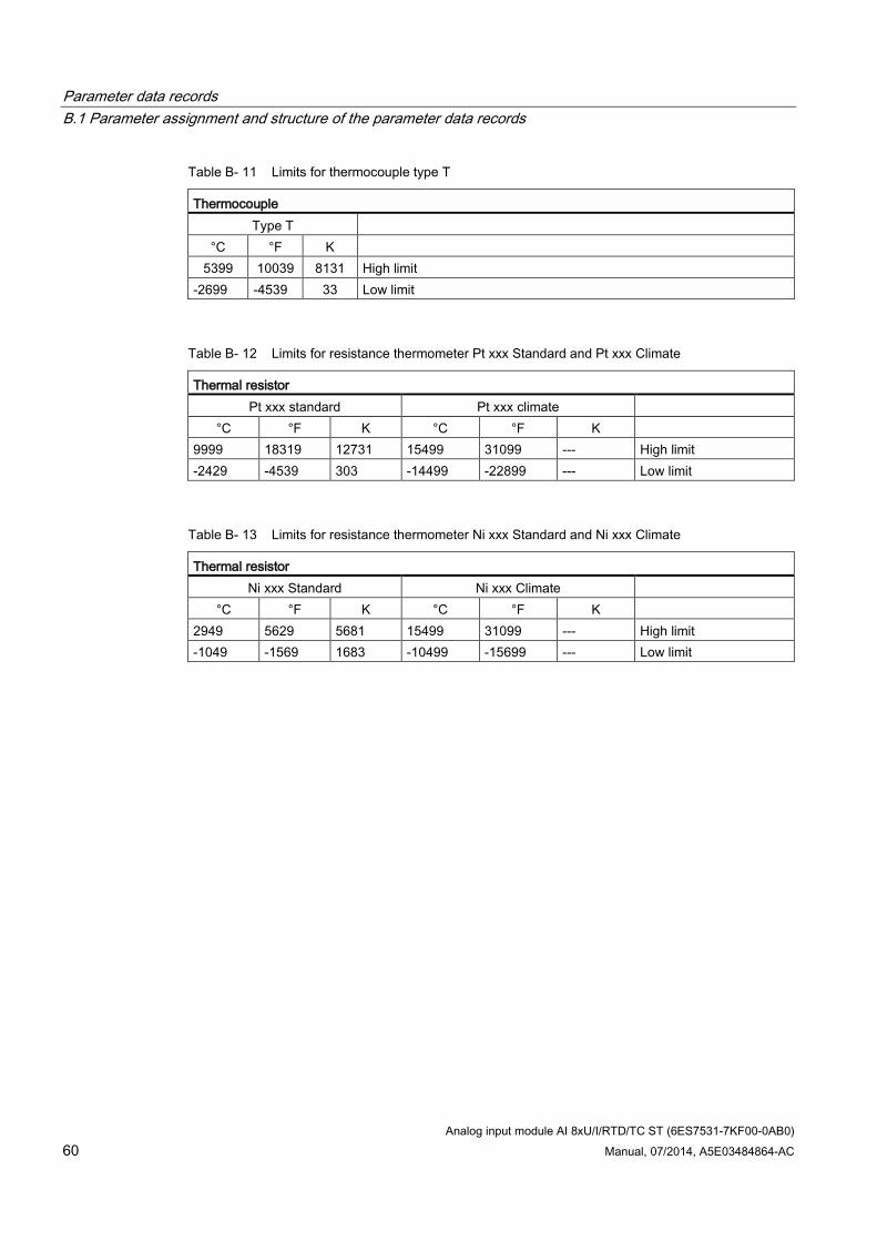
Table B- 11 Limits for thermocouple type T
Thermocouple Type T
°C °F K 5399 10039 8131 High limit
-2699 -4539 33 Low limit
Table B- 12 Limits for resistance thermometer Pt xxx Standard and Pt xxx Climate
Thermal resistor Pt xxx standard Pt xxx climate
°C °F K °C °F K 9999 18319 12731 15499 31099 --- High limit -2429 -4539 303 -14499 -22899 --- Low limit
Table B- 13 Limits for resistance thermometer Ni xxx Standard and Ni xxx Climate
Thermal resistor Ni xxx Standard Ni xxx Climate
°C °F K °C °F K 2949 5629 5681 15499 31099 --- High limit -1049 -1569 1683 -10499 -15699 --- Low limit
Parameter data records B.2 Structure of a data record for dynamic reference temperature
Analog input module AI 8xU/I/RTD/TC ST (6ES7531-7KF00-0AB0) Manual, 07/2014, A5E03484864-AC 61
B.2 Structure of a data record for dynamic reference temperature The WRREC instruction is used to transfer the reference junction temperature via data record 192 to data record 199 to the module.
The description of the WRREC instruction can be found in the online help from STEP 7.
If you have set the "Dynamic reference temperature" value for the "Reference junction" parameter, the module expects a new data record at least every 5 minutes. If the module does not receive a new data record within this time, it generates the "Reference channel error" diagnostics message.
Assignment of data record and channel The following assignment applies if no submodules (1 x 8-channel) are configured for the module:
Data record 192 for channel 0
Data record 193 for channel 1
Data record 194 for channel 2
Data record 195 for channel 3
Data record 196 for channel 4
Data record 197 for channel 5
Data record 198 for channel 6
Data record 199 for channel 7
If eight submodules (8 x 1-channel) are configured for the module, each submodule has only one channel. The parameters of the channel are in data record 192.
Background: Each submodule you address for the data record transfer has only one channel.
Parameter data records B.2 Structure of a data record for dynamic reference temperature
Analog input module AI 8xU/I/RTD/TC ST (6ES7531-7KF00-0AB0) 62 Manual, 07/2014, A5E03484864-AC
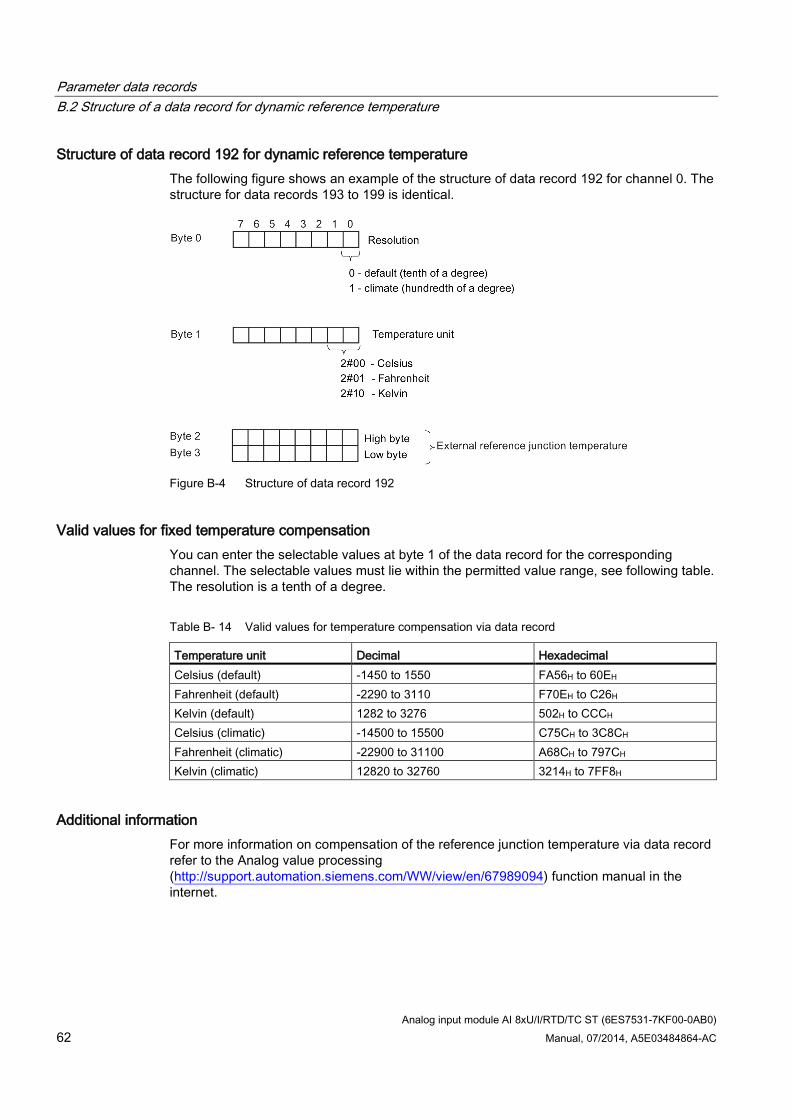
Structure of data record 192 for dynamic reference temperature The following figure shows an example of the structure of data record 192 for channel 0. The structure for data records 193 to 199 is identical.
Figure B-4 Structure of data record 192
Valid values for fixed temperature compensation You can enter the selectable values at byte 1 of the data record for the corresponding channel. The selectable values must lie within the permitted value range, see following table. The resolution is a tenth of a degree.
Table B- 14 Valid values for temperature compensation via data record
Temperature unit Decimal Hexadecimal Celsius (default) -1450 to 1550 FA56H to 60EH Fahrenheit (default) -2290 to 3110 F70EH to C26H Kelvin (default) 1282 to 3276 502H to CCCH Celsius (climatic) -14500 to 15500 C75CH to 3C8CH Fahrenheit (climatic) -22900 to 31100 A68CH to 797CH Kelvin (climatic) 12820 to 32760 3214H to 7FF8H
Additional information For more information on compensation of the reference junction temperature via data record refer to the Analog value processing (http://support.automation.siemens.com/WW/view/en/67989094) function manual in the internet.
Analog input module AI 8xU/I/RTD/TC ST (6ES7531-7KF00-0AB0) Manual, 07/2014, A5E03484864-AC 63
Representation of analog values C
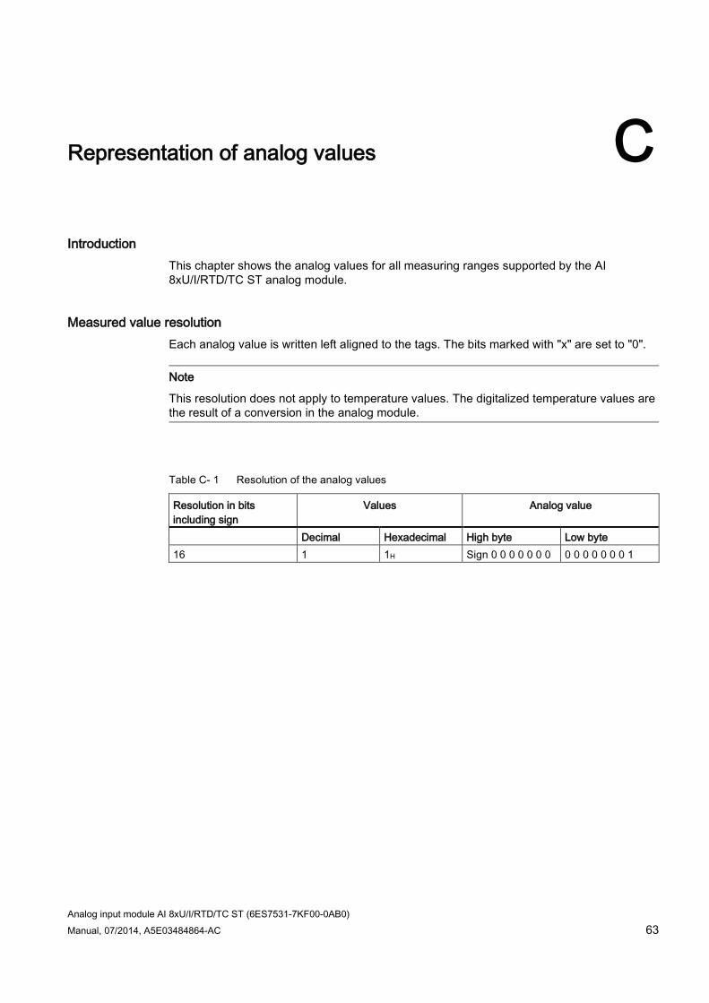
Introduction This chapter shows the analog values for all measuring ranges supported by the AI 8xU/I/RTD/TC ST analog module.
Measured value resolution Each analog value is written left aligned to the tags. The bits marked with "x" are set to "0".
Note
This resolution does not apply to temperature values. The digitalized temperature values are the result of a conversion in the analog module.
Table C- 1 Resolution of the analog values
Resolution in bits including sign
Values Analog value
Decimal Hexadecimal High byte Low byte 16 1 1H Sign 0 0 0 0 0 0 0 0 0 0 0 0 0 0 1
Representation of analog values C.1 Representation of input ranges
Analog input module AI 8xU/I/RTD/TC ST (6ES7531-7KF00-0AB0) 64 Manual, 07/2014, A5E03484864-AC
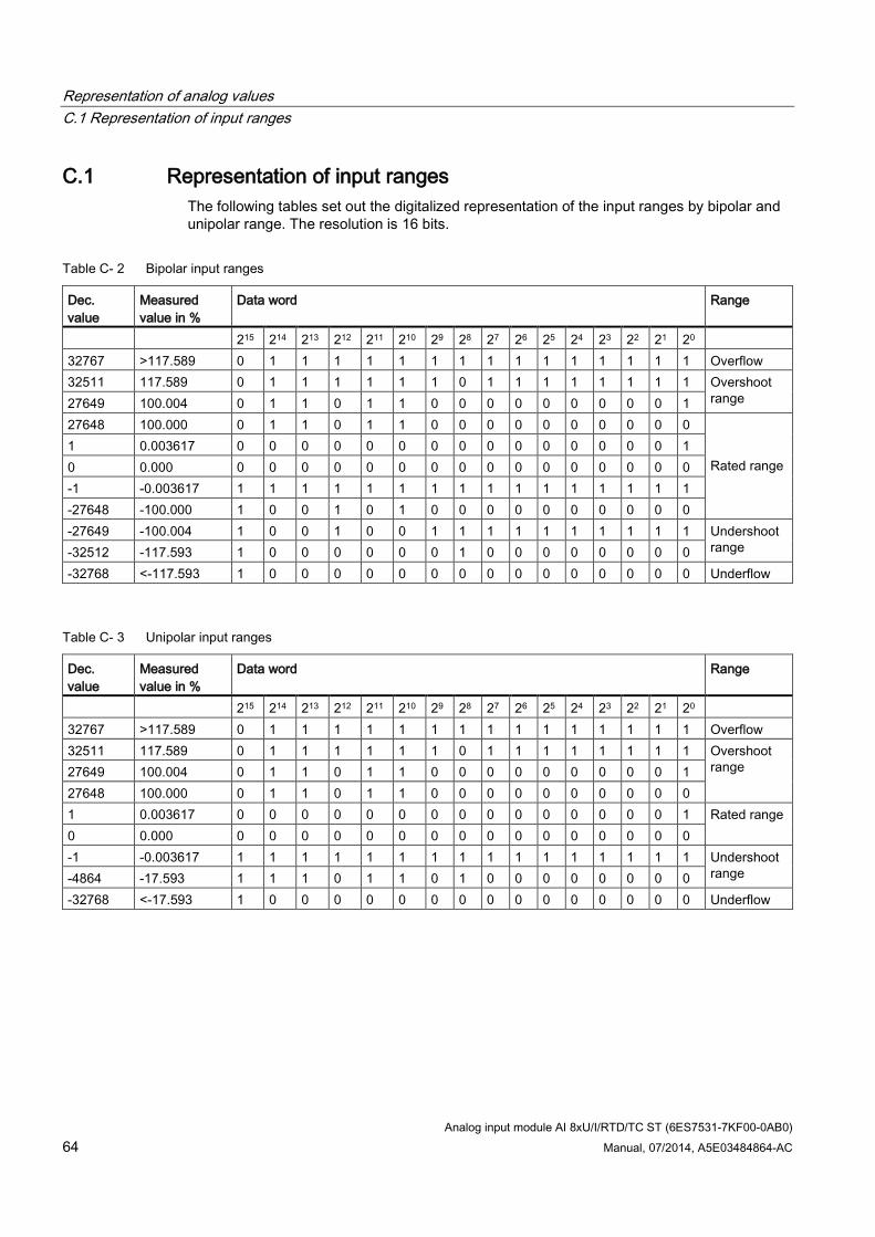
C.1 Representation of input ranges The following tables set out the digitalized representation of the input ranges by bipolar and unipolar range. The resolution is 16 bits.
Table C- 2 Bipolar input ranges
Dec. value
Measured value in %
Data word Range
215 214 213 212 211 210 29 28 27 26 25 24 23 22 21 20 32767 >117.589 0 1 1 1 1 1 1 1 1 1 1 1 1 1 1 1 Overflow 32511 117.589 0 1 1 1 1 1 1 0 1 1 1 1 1 1 1 1 Overshoot
range 27649 100.004 0 1 1 0 1 1 0 0 0 0 0 0 0 0 0 1 27648 100.000 0 1 1 0 1 1 0 0 0 0 0 0 0 0 0 0
Rated range
1 0.003617 0 0 0 0 0 0 0 0 0 0 0 0 0 0 0 1 0 0.000 0 0 0 0 0 0 0 0 0 0 0 0 0 0 0 0 -1 -0.003617 1 1 1 1 1 1 1 1 1 1 1 1 1 1 1 1 -27648 -100.000 1 0 0 1 0 1 0 0 0 0 0 0 0 0 0 0 -27649 -100.004 1 0 0 1 0 0 1 1 1 1 1 1 1 1 1 1 Undershoot
range -32512 -117.593 1 0 0 0 0 0 0 1 0 0 0 0 0 0 0 0 -32768 <-117.593 1 0 0 0 0 0 0 0 0 0 0 0 0 0 0 0 Underflow
Table C- 3 Unipolar input ranges
Dec. value
Measured value in %
Data word Range
215 214 213 212 211 210 29 28 27 26 25 24 23 22 21 20 32767 >117.589 0 1 1 1 1 1 1 1 1 1 1 1 1 1 1 1 Overflow 32511 117.589 0 1 1 1 1 1 1 0 1 1 1 1 1 1 1 1 Overshoot
range 27649 100.004 0 1 1 0 1 1 0 0 0 0 0 0 0 0 0 1 27648 100.000 0 1 1 0 1 1 0 0 0 0 0 0 0 0 0 0 1 0.003617 0 0 0 0 0 0 0 0 0 0 0 0 0 0 0 1 Rated range 0 0.000 0 0 0 0 0 0 0 0 0 0 0 0 0 0 0 0 -1 -0.003617 1 1 1 1 1 1 1 1 1 1 1 1 1 1 1 1 Undershoot
range -4864 -17.593 1 1 1 0 1 1 0 1 0 0 0 0 0 0 0 0 -32768 <-17.593 1 0 0 0 0 0 0 0 0 0 0 0 0 0 0 0 Underflow
Representation of analog values C.2 Representation of analog values in voltage measuring ranges
Analog input module AI 8xU/I/RTD/TC ST (6ES7531-7KF00-0AB0) Manual, 07/2014, A5E03484864-AC 65
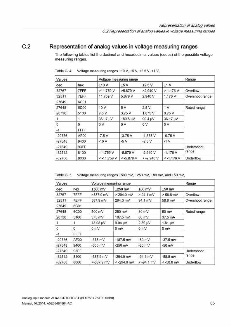
C.2 Representation of analog values in voltage measuring ranges The following tables list the decimal and hexadecimal values (codes) of the possible voltage measuring ranges.
Table C- 4 Voltage measuring ranges ±10 V, ±5 V, ±2.5 V, ±1 V,
Values Voltage measuring range Range dec hex ±10 V ±5 V ±2.5 V ±1 V 32767 7FFF >11.759 V >5.879 V >2.940 V > 1.176 V Overflow 32511 7EFF 11.759 V 5.879 V 2.940 V 1.176 V Overshoot range 27649 6C01 27648 6C00 10 V 5 V 2.5 V 1 V Rated range 20736 5100 7.5 V 3.75 V 1.875 V 0.75 V 1 1 361.7 µV 180.8 µV 90.4 µV 36.17 µV 0 0 0 V 0 V 0 V 0 V -1 FFFF -20736 AF00 -7.5 V -3.75 V -1.875 V -0.75 V -27648 9400 -10 V -5 V -2.5 V -1 V -27649 93FF Undershoot
range -32512 8100 -11.759 V -5.879 V -2.940 V -1.176 V -32768 8000 < -11.759 V < -5.879 V < -2.940 V < -1.176 V Underflow
Table C- 5 Voltage measuring ranges ±500 mV, ±250 mV, ±80 mV, and ±50 mV,
Values Voltage measuring range Range dec hex ±500 mV ±250 mV ±80 mV ±50 mV 32767 7FFF >587.9 mV > 294.0 mV > 94.1 mV > 58.8 mV Overflow 32511 7EFF 587.9 mV 294.0 mV 94.1 mV 58.8 mV Overshoot range 27649 6C01 27648 6C00 500 mV 250 mV 80 mV 50 mV Rated range 20736 5100 375 mV 187.5 mV 60 mV 37.5 mA 1 1 18.08 µV 9.04 µV 2.89 µV 1.81 µV 0 0 0 mV 0 mV 0 mV 0 mV -1 FFFF -20736 AF00 -375 mV -187.5 mV -60 mV -37.5 mV -27648 9400 -500 mV -250 mV -80 mV -50 mV -27649 93FF Undershoot
range -32512 8100 -587.9 mV -294.0 mV -94.1 mV -58.8 mV -32768 8000 <-587.9 mV < -294.0 mV < -94.1 mV < -58.8 mV Underflow
Representation of analog values C.2 Representation of analog values in voltage measuring ranges
Analog input module AI 8xU/I/RTD/TC ST (6ES7531-7KF00-0AB0) 66 Manual, 07/2014, A5E03484864-AC
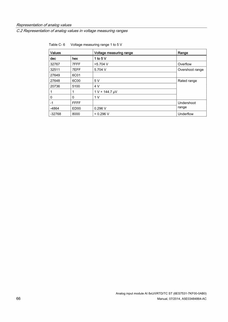
Table C- 6 Voltage measuring range 1 to 5 V
Values Voltage measuring range Range dec hex 1 to 5 V 32767 7FFF >5.704 V Overflow 32511 7EFF 5.704 V Overshoot range 27649 6C01 27648 6C00 5 V Rated range 20736 5100 4 V 1 1 1 V + 144.7 µV 0 0 1 V -1 FFFF Undershoot
range -4864 ED00 0.296 V -32768 8000 < 0.296 V Underflow
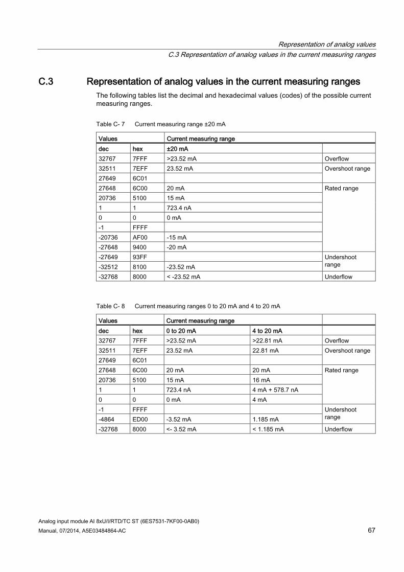
Representation of analog values C.3 Representation of analog values in the current measuring ranges
Analog input module AI 8xU/I/RTD/TC ST (6ES7531-7KF00-0AB0) Manual, 07/2014, A5E03484864-AC 67
C.3 Representation of analog values in the current measuring ranges The following tables list the decimal and hexadecimal values (codes) of the possible current measuring ranges.
Table C- 7 Current measuring range ±20 mA
Values Current measuring range dec hex ±20 mA 32767 7FFF >23.52 mA Overflow 32511 7EFF 23.52 mA Overshoot range 27649 6C01 27648 6C00 20 mA Rated range 20736 5100 15 mA 1 1 723.4 nA 0 0 0 mA -1 FFFF -20736 AF00 -15 mA -27648 9400 -20 mA -27649 93FF Undershoot
range -32512 8100 -23.52 mA -32768 8000 < -23.52 mA Underflow
Table C- 8 Current measuring ranges 0 to 20 mA and 4 to 20 mA
Values Current measuring range dec hex 0 to 20 mA 4 to 20 mA 32767 7FFF >23.52 mA >22.81 mA Overflow 32511 7EFF 23.52 mA 22.81 mA Overshoot range 27649 6C01 27648 6C00 20 mA 20 mA Rated range 20736 5100 15 mA 16 mA 1 1 723.4 nA 4 mA + 578.7 nA 0 0 0 mA 4 mA -1 FFFF Undershoot
range -4864 ED00 -3.52 mA 1.185 mA -32768 8000 <- 3.52 mA < 1.185 mA Underflow
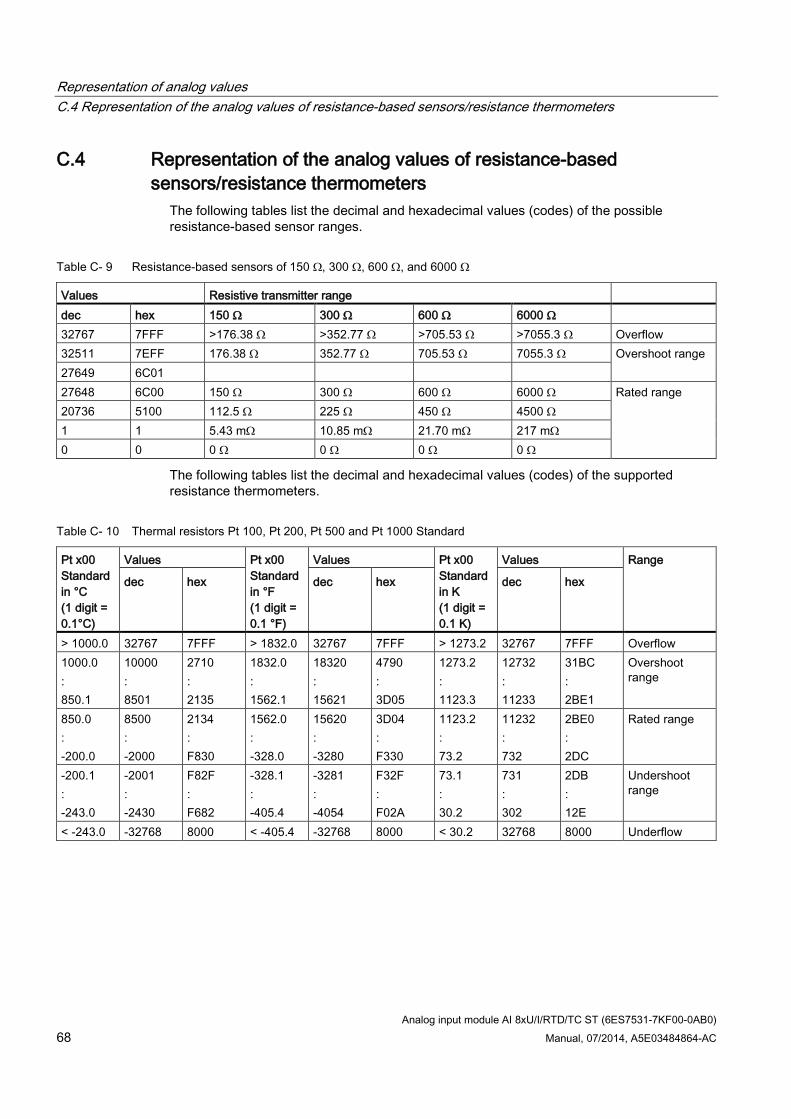
Representation of analog values C.4 Representation of the analog values of resistance-based sensors/resistance thermometers
Analog input module AI 8xU/I/RTD/TC ST (6ES7531-7KF00-0AB0) 68 Manual, 07/2014, A5E03484864-AC
C.4 Representation of the analog values of resistance-based sensors/resistance thermometers
The following tables list the decimal and hexadecimal values (codes) of the possible resistance-based sensor ranges.
Table C- 9 Resistance-based sensors of 150 Ω, 300 Ω, 600 Ω, and 6000 Ω
Values Resistive transmitter range dec hex 150 Ω 300 Ω 600 Ω 6000 Ω 32767 7FFF >176.38 Ω >352.77 Ω >705.53 Ω >7055.3 Ω Overflow 32511 7EFF 176.38 Ω 352.77 Ω 705.53 Ω 7055.3 Ω Overshoot range 27649 6C01 27648 6C00 150 Ω 300 Ω 600 Ω 6000 Ω Rated range 20736 5100 112.5 Ω 225 Ω 450 Ω 4500 Ω 1 1 5.43 mΩ 10.85 mΩ 21.70 mΩ 217 mΩ 0 0 0 Ω 0 Ω 0 Ω 0 Ω
The following tables list the decimal and hexadecimal values (codes) of the supported resistance thermometers.
Table C- 10 Thermal resistors Pt 100, Pt 200, Pt 500 and Pt 1000 Standard
Pt x00 Standard in °C (1 digit = 0.1°C)
Values Pt x00 Standard in °F (1 digit = 0.1 °F)
Values Pt x00 Standard in K (1 digit = 0.1 K)
Values Range
dec hex dec hex dec hex
> 1000.0 32767 7FFF > 1832.0 32767 7FFF > 1273.2 32767 7FFF Overflow 1000.0 : 850.1
10000 : 8501
2710 : 2135
1832.0 : 1562.1
18320 : 15621
4790 : 3D05
1273.2 : 1123.3
12732 : 11233
31BC : 2BE1
Overshoot range
850.0 : -200.0
8500 : -2000
2134 : F830
1562.0 : -328.0
15620 : -3280
3D04 : F330
1123.2 : 73.2
11232 : 732
2BE0 : 2DC
Rated range
-200.1 : -243.0
-2001 : -2430
F82F : F682
-328.1 : -405.4
-3281 : -4054
F32F : F02A
73.1 : 30.2
731 : 302
2DB : 12E
Undershoot range
< -243.0 -32768 8000 < -405.4 -32768 8000 < 30.2 32768 8000 Underflow
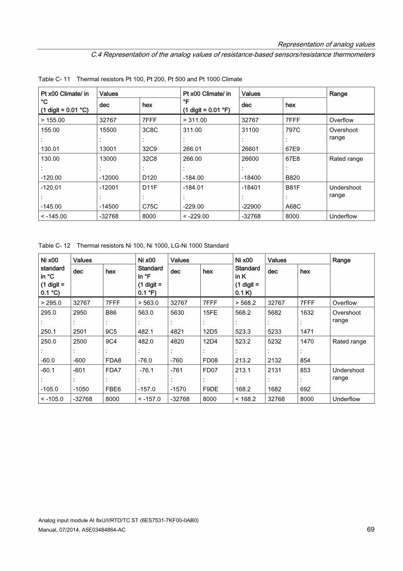
Representation of analog values C.4 Representation of the analog values of resistance-based sensors/resistance thermometers
Analog input module AI 8xU/I/RTD/TC ST (6ES7531-7KF00-0AB0) Manual, 07/2014, A5E03484864-AC 69
Table C- 11 Thermal resistors Pt 100, Pt 200, Pt 500 and Pt 1000 Climate
Pt x00 Climate/ in °C (1 digit = 0.01 °C)
Values Pt x00 Climate/ in °F (1 digit = 0.01 °F)
Values Range
dec hex dec hex
> 155.00 32767 7FFF > 311.00 32767 7FFF Overflow 155.00 : 130.01
15500 : 13001
3C8C : 32C9
311.00 : 266.01
31100 : 26601
797C : 67E9
Overshoot range
130.00 : -120.00
13000 : -12000
32C8 : D120
266.00 : -184.00
26600 : -18400
67E8 : B820
Rated range
-120.01 : -145.00
-12001 : -14500
D11F : C75C
-184.01 : -229.00
-18401 : -22900
B81F : A68C
Undershoot range
< -145.00 -32768 8000 < -229.00 -32768 8000 Underflow
Table C- 12 Thermal resistors Ni 100, Ni 1000, LG-Ni 1000 Standard
Ni x00 standard in °C (1 digit = 0.1 °C)
Values Ni x00 Standard in °F (1 digit = 0.1 °F)
Values Ni x00 Standard in K (1 digit = 0.1 K)
Values Range
dec hex dec hex dec hex
> 295.0 32767 7FFF > 563.0 32767 7FFF > 568.2 32767 7FFF Overflow 295.0 : 250.1
2950 : 2501
B86 : 9C5
563.0 : 482.1
5630 : 4821
15FE : 12D5
568.2 : 523.3
5682 : 5233
1632 : 1471
Overshoot range
250.0 : -60.0
2500 : -600
9C4 : FDA8
482.0 : -76.0
4820 : -760
12D4 : FD08
523.2 : 213.2
5232 : 2132
1470 : 854
Rated range
-60.1 : -105.0
-601 : -1050
FDA7 : FBE6
-76.1 : -157.0
-761 : -1570
FD07 : F9DE
213.1 : 168.2
2131 : 1682
853 : 692
Undershoot range
< -105.0 -32768 8000 < -157.0 -32768 8000 < 168.2 32768 8000 Underflow
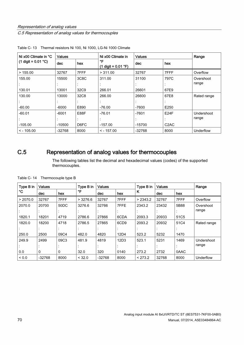
Representation of analog values C.5 Representation of analog values for thermocouples
Analog input module AI 8xU/I/RTD/TC ST (6ES7531-7KF00-0AB0) 70 Manual, 07/2014, A5E03484864-AC
Table C- 13 Thermal resistors Ni 100, Ni 1000, LG-Ni 1000 Climate
Ni x00 Climate in °C (1 digit = 0.01 °C)
Values Ni x00 Climate in °F (1 digit = 0.01 °F)
Values Range
dec hex dec hex
> 155.00 32767 7FFF > 311.00 32767 7FFF Overflow 155.00 : 130.01
15500 : 13001
3C8C : 32C9
311.00 : 266.01
31100 : 26601
797C : 67E9
Overshoot range
130.00 : -60.00
13000 : -6000
32C8 : E890
266.00 : -76.00
26600 : -7600
67E8 : E250
Rated range
-60.01 : -105.00
-6001 : -10500
E88F : D6FC
-76.01 : -157.00
-7601 : -15700
E24F : C2AC
Undershoot range
< - 105.00 -32768 8000 < - 157.00 -32768 8000 Underflow
C.5 Representation of analog values for thermocouples The following tables list the decimal and hexadecimal values (codes) of the supported thermocouples.
Table C- 14 Thermocouple type B
Type B in °C
Values Type B in °F
Values Type B in K
Values Range
dec hex dec hex dec hex > 2070.0 32767 7FFF > 3276.6 32767 7FFF > 2343.2 32767 7FFF Overflow 2070.0 : 1820.1
20700 : 18201
50DC : 4719
3276.6 : 2786.6
32766 : 27866
7FFE : 6CDA
2343.2 : 2093.3
23432 : 20933
5B88 : 51C5
Overshoot range
1820.0 : 250.0
18200 : 2500
4718 : 09C4
2786.5 : 482.0
27865 : 4820
6CD9 : 12D4
2093.2 : 523.2
20932 : 5232
51C4 : 1470
Rated range
249.9 : 0.0
2499 : 0
09C3 : 0
481.9 : 32.0
4819 : 320
12D3 : 0140
523.1 : 273.2
5231 : 2732
1469 : 0AAC
Undershoot range
< 0.0 -32768 8000 < 32.0 -32768 8000 < 273.2 32768 8000 Underflow
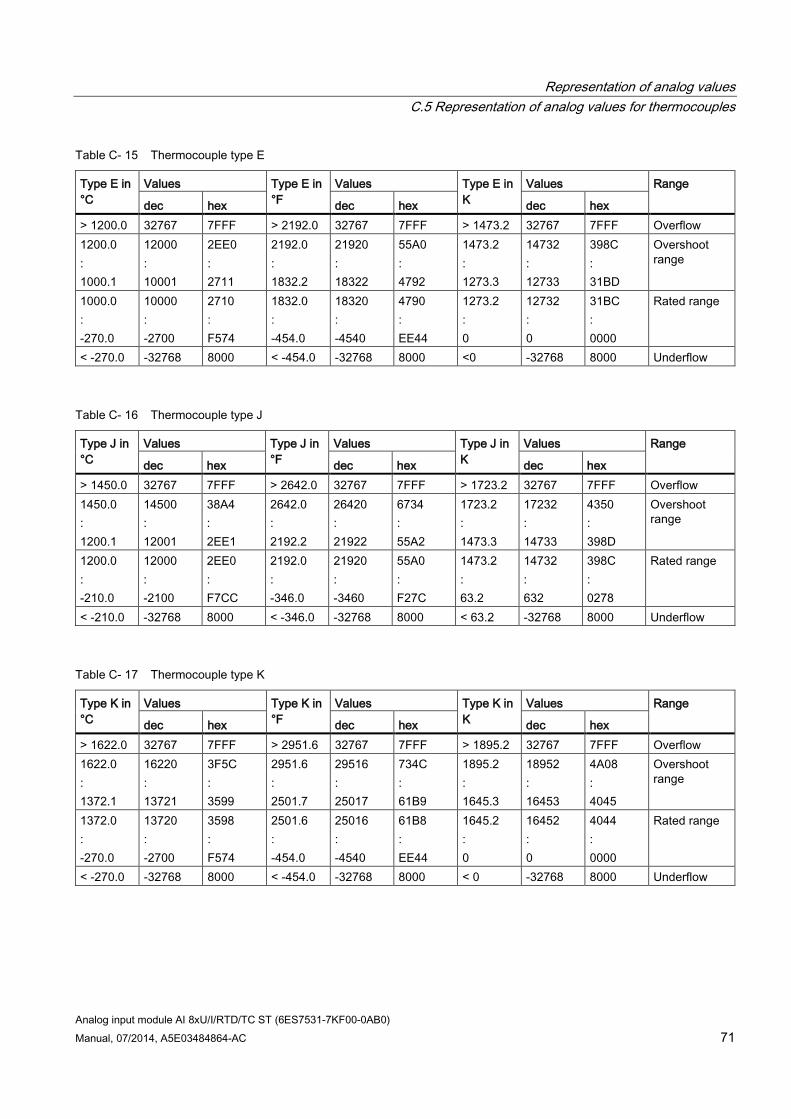
Representation of analog values C.5 Representation of analog values for thermocouples
Analog input module AI 8xU/I/RTD/TC ST (6ES7531-7KF00-0AB0) Manual, 07/2014, A5E03484864-AC 71
Table C- 15 Thermocouple type E
Type E in °C
Values Type E in °F
Values Type E in K
Values Range
dec hex dec hex dec hex > 1200.0 32767 7FFF > 2192.0 32767 7FFF > 1473.2 32767 7FFF Overflow 1200.0 : 1000.1
12000 : 10001
2EE0 : 2711
2192.0 : 1832.2
21920 : 18322
55A0 : 4792
1473.2 : 1273.3
14732 : 12733
398C : 31BD
Overshoot range
1000.0 : -270.0
10000 : -2700
2710 : F574
1832.0 : -454.0
18320 : -4540
4790 : EE44
1273.2 : 0
12732 : 0
31BC : 0000
Rated range
< -270.0 -32768 8000 < -454.0 -32768 8000 <0 -32768 8000 Underflow
Table C- 16 Thermocouple type J
Type J in °C
Values Type J in °F
Values Type J in K
Values Range
dec hex dec hex dec hex > 1450.0 32767 7FFF > 2642.0 32767 7FFF > 1723.2 32767 7FFF Overflow 1450.0 : 1200.1
14500 : 12001
38A4 : 2EE1
2642.0 : 2192.2
26420 : 21922
6734 : 55A2
1723.2 : 1473.3
17232 : 14733
4350 : 398D
Overshoot range
1200.0 : -210.0
12000 : -2100
2EE0 : F7CC
2192.0 : -346.0
21920 : -3460
55A0 : F27C
1473.2 : 63.2
14732 : 632
398C : 0278
Rated range
< -210.0 -32768 8000 < -346.0 -32768 8000 < 63.2 -32768 8000 Underflow
Table C- 17 Thermocouple type K
Type K in °C
Values Type K in °F
Values Type K in K
Values Range
dec hex dec hex dec hex > 1622.0 32767 7FFF > 2951.6 32767 7FFF > 1895.2 32767 7FFF Overflow 1622.0 : 1372.1
16220 : 13721
3F5C : 3599
2951.6 : 2501.7
29516 : 25017
734C : 61B9
1895.2 : 1645.3
18952 : 16453
4A08 : 4045
Overshoot range
1372.0 : -270.0
13720 : -2700
3598 : F574
2501.6 : -454.0
25016 : -4540
61B8 : EE44
1645.2 : 0
16452 : 0
4044 : 0000
Rated range
< -270.0 -32768 8000 < -454.0 -32768 8000 < 0 -32768 8000 Underflow
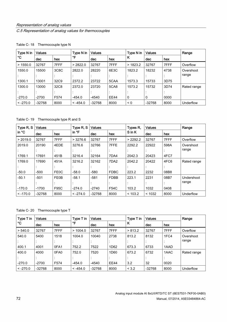
Representation of analog values C.5 Representation of analog values for thermocouples
Analog input module AI 8xU/I/RTD/TC ST (6ES7531-7KF00-0AB0) 72 Manual, 07/2014, A5E03484864-AC
Table C- 18 Thermocouple type N
Type N in °C
Values Type N in °F
Values Type N in K
Values Range
dec hex dec hex dec hex > 1550.0 32767 7FFF > 2822.0 32767 7FFF > 1823.2 32767 7FFF Overflow 1550.0 : 1300.1
15500 : 13001
3C8C : 32C9
2822.0 : 2372.2
28220 : 23722
6E3C : 5CAA
1823.2 : 1573.3
18232 : 15733
4738 : 3D75
Overshoot range
1300.0 : -270.0
13000 : -2700
32C8 : F574
2372.0 : -454.0
23720 : -4540
5CA8 : EE44
1573.2 : 0
15732 : 0
3D74 : 0000
Rated range
< -270.0 -32768 8000 < -454.0 -32768 8000 < 0 -32768 8000 Underflow
Table C- 19 Thermocouple type R and S
Type R, S in °C
Values Type R, S in °F
Values Types R, S in K
Values Range
dec hex dec hex dec hex > 2019.0 32767 7FFF > 3276.6 32767 7FFF > 2292.2 32767 7FFF Overflow 2019.0 : 1769.1
20190 : 17691
4EDE : 451B
3276.6 : 3216.4
32766 : 32164
7FFE : 7DA4
2292.2 : 2042.3
22922 : 20423
598A : 4FC7
Overshoot range
1769.0 : -50.0
17690 : -500
451A : FE0C
3216.2 : -58.0
32162 : -580
7DA2 : FDBC
2042.2 : 223.2
20422 : 2232
4FC6 : 08B8
Rated range
-50.1 : -170.0
-501 : -1700
FE0B : F95C
-58.1 : -274.0
-581 : -2740
FDBB : F54C
223.1 : 103.2
2231 : 1032
08B7 : 0408
Undershoot range
< -170.0 -32768 8000 < -274.0 -32768 8000 < 103.2 < 1032 8000 Underflow
Table C- 20 Thermocouple type T
Type T in °C
Values Type T in °F
Values Type T in K
Values Range
dec hex dec hex dec hex > 540.0 32767 7FFF > 1004.0 32767 7FFF > 813.2 32767 7FFF Overflow 540.0 : 400.1
5400 : 4001
1518 : 0FA1
1004.0 : 752.2
10040 : 7522
2738 : 1D62
813.2 : 673.3
8132 : 6733
1FC4 : 1AAD
Overshoot range
400.0 : -270.0
4000 : -2700
0FA0 : F574
752.0 : -454.0
7520 : -4540
1D60 : EE44
673.2 : 3.2
6732 : 32
1AAC : 0020
Rated range
< -270.0 -32768 8000 < -454.0 -32768 8000 < 3.2 -32768 8000 Underflow
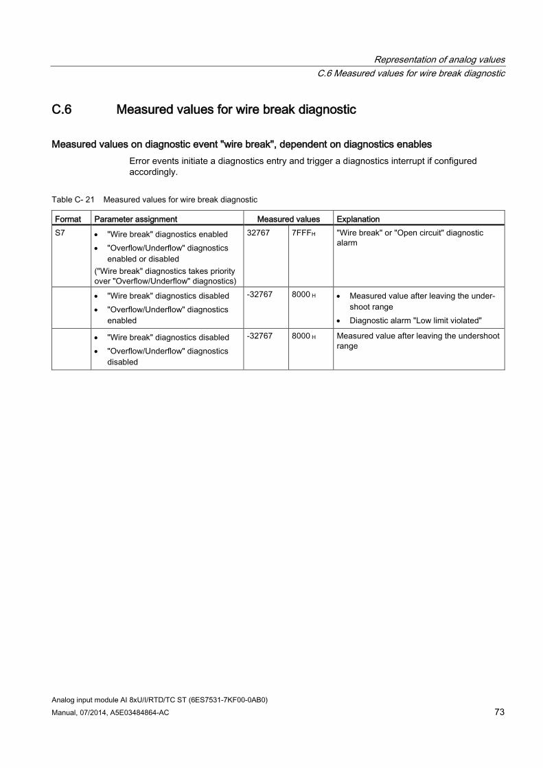
Representation of analog values C.6 Measured values for wire break diagnostic
Analog input module AI 8xU/I/RTD/TC ST (6ES7531-7KF00-0AB0) Manual, 07/2014, A5E03484864-AC 73
C.6 Measured values for wire break diagnostic
Measured values on diagnostic event "wire break", dependent on diagnostics enables Error events initiate a diagnostics entry and trigger a diagnostics interrupt if configured accordingly.
Table C- 21 Measured values for wire break diagnostic
Format Parameter assignment Measured values Explanation S7 • "Wire break" diagnostics enabled
• "Overflow/Underflow" diagnostics enabled or disabled
("Wire break" diagnostics takes priority over "Overflow/Underflow" diagnostics)
32767 7FFFH "Wire break" or "Open circuit" diagnostic alarm
• "Wire break" diagnostics disabled • "Overflow/Underflow" diagnostics
enabled
-32767 8000 H • Measured value after leaving the under-shoot range
• Diagnostic alarm "Low limit violated"
• "Wire break" diagnostics disabled • "Overflow/Underflow" diagnostics
disabled
-32767 8000 H Measured value after leaving the undershoot range
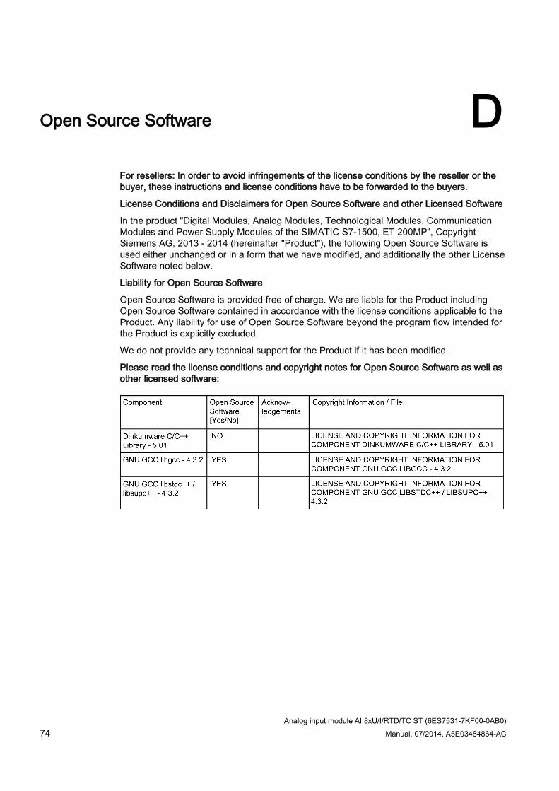
Analog input module AI 8xU/I/RTD/TC ST (6ES7531-7KF00-0AB0) 74 Manual, 07/2014, A5E03484864-AC
Open Source Software D
For resellers: In order to avoid infringements of the license conditions by the reseller or the buyer, these instructions and license conditions have to be forwarded to the buyers.
License Conditions and Disclaimers for Open Source Software and other Licensed Software
In the product "Digital Modules, Analog Modules, Technological Modules, Communication Modules and Power Supply Modules of the SIMATIC S7-1500, ET 200MP", Copyright Siemens AG, 2013 - 2014 (hereinafter "Product"), the following Open Source Software is used either unchanged or in a form that we have modified, and additionally the other License Software noted below.
Liability for Open Source Software
Open Source Software is provided free of charge. We are liable for the Product including Open Source Software contained in accordance with the license conditions applicable to the Product. Any liability for use of Open Source Software beyond the program flow intended for the Product is explicitly excluded.
We do not provide any technical support for the Product if it has been modified.
Please read the license conditions and copyright notes for Open Source Software as well as other licensed software:
Open Source Software
Analog input module AI 8xU/I/RTD/TC ST (6ES7531-7KF00-0AB0) Manual, 07/2014, A5E03484864-AC 75
Open Source Software
Analog input module AI 8xU/I/RTD/TC ST (6ES7531-7KF00-0AB0) 76 Manual, 07/2014, A5E03484864-AC
Open Source Software
Analog input module AI 8xU/I/RTD/TC ST (6ES7531-7KF00-0AB0) Manual, 07/2014, A5E03484864-AC 77
Open Source Software
Analog input module AI 8xU/I/RTD/TC ST (6ES7531-7KF00-0AB0) 78 Manual, 07/2014, A5E03484864-AC
Open Source Software
Analog input module AI 8xU/I/RTD/TC ST (6ES7531-7KF00-0AB0) Manual, 07/2014, A5E03484864-AC 79
Open Source Software
Analog input module AI 8xU/I/RTD/TC ST (6ES7531-7KF00-0AB0) 80 Manual, 07/2014, A5E03484864-AC
Open Source Software
Analog input module AI 8xU/I/RTD/TC ST (6ES7531-7KF00-0AB0) Manual, 07/2014, A5E03484864-AC 81
Open Source Software
Analog input module AI 8xU/I/RTD/TC ST (6ES7531-7KF00-0AB0) 82 Manual, 07/2014, A5E03484864-AC
Open Source Software
Analog input module AI 8xU/I/RTD/TC ST (6ES7531-7KF00-0AB0) Manual, 07/2014, A5E03484864-AC 83
Open Source Software
Analog input module AI 8xU/I/RTD/TC ST (6ES7531-7KF00-0AB0) 84 Manual, 07/2014, A5E03484864-AC
Open Source Software
Analog input module AI 8xU/I/RTD/TC ST (6ES7531-7KF00-0AB0) Manual, 07/2014, A5E03484864-AC 85