Embed Size (px)
Citation preview

Siemens MP 12 · 2003
Analog indicators
1/2 Regulations and standards
1/4 Technical descriptions
1/7 Rectangular indicators for direct current or voltage
1/7 96 x 48 mm and 48 x 96 mmwith moving-coil movement
1/10 144 x 72 mm and 72 x 144 mmwith moving-coil movement
1/13 Square indicators for direct current or voltage
1/13 72 x 72 mm with moving-coil movement1/16 96 x 96 mm with moving-coil movement
1/19 Square indicators for alternating current or voltage, 15 to 65 Hz
1/19 72 x 72 mm with moving-iron movement1/22 96 x 96 mm with moving-iron movement
1/25 Square indicators for alternating current
1/25 96 x 96 mm with bimetal movementfor mean and maximum value
1/27 72 x 72 mm with bimetal moving-iron movement for mean, maximum and instantaneous value
1/29 96 x 96 mm with bimetal moving-iron movement for mean, maximum and instantaneous value

Analog indicatorsRegulations and standards
1
Our indicators meet the specifications of the European Directive 73/23/EWG and 89/336/EWG, proven by compliance with the fol-lowing standards:7 DIN 57 410 or VDE 0410 (Safety requirements for indicatingand recording instruments and their accessories)7 IEC 60 051/EN 60 051/DIN EN 60 051 (Measuring instruments
with scale indication)7 EN 50 081-2: 1993 EMC (emitted interference, industrial sec-
tor)7 EN 50 082-2: 1995 EMC (immunity, industrial sector)
The following explains the key specifications of these regulations for the building of electrical measuring instruments and their re-quired properties.
Accuracy
The accuracy of a measuring intstrument is given through the limits of intrinsic errors and influence errors.
An error that is determined when the instrument and/or its acces-sories is/are under reference conditions (Tab. I-1 DIN EN 60 051) is referred to as an intrinsic error, as opposed to an influence er-ror, which occurs when the instrument is not under reference conditions, but within the limits of its nominal range of use (Tab. II-1 DIN EN 60 051).
Our indicators correspond to Class 1.5, unless another accuracy class rating is specified for individual types. As a further option, it may also be possible to customize the measuring instruments for higher accuracy class rating (Class 1).
The class is specified on the scale, e.g.:
1.5 accuracy class index for indication errors, output in a per-centage of the reference value.
The reference value generally corresponds to the higher-mea-suring range value with the following exceptions:
The reference value corresponds to:• the sum of the electrical values, which correspond to the limits
of the measuring range, independent of sign, when both the mechanical and the electrical zero points are within the scale.
• the length of the scale for instruments with non-linear contract-ing scales that do not have a separate linear scale.
Reference values and influence errors
Service position
The nominal position is usually indicated by a position mark. For instruments without a position mark, the reference area for each position lies between horizontal and vertical.
The nominal range of use is 5° in each direction starting from the reference position, whereby the influence error (in addition to the indication error) must not be greater than 50 % of the corre-sponding class error.
Possible nominal mounting positions
Operating temperature range
Unless otherwise specified, instruments of Class 0.5 - 5 must op-erate continuously in ambient temperatures of -25 and +40 °C, without causing permanent damage.
Temperature influence
Unless otherwise specified, the reference temperature is 23 °C ± 2 K for instruments of Classes 0.5 - 5.
Nominal range of use is the reference temperature ±10 K. Any additional errors within this temperature range may not be greater than the class error.
Vibration and mechanical impact resistance
Influence conditions for vibration and impacts are specified in DIN EN 60 051. Our measuring instruments comply with these requirements and can be supplied as follows (for feasibility, see relevant data sheet):
Effects of vibration and impact
Unless otherwise specified, measuring instruments and acces-sories with accuracy class index 1 and higher must withstand the following shake and impact tests as type tests:
Mechanical strength Impact resistance Vibration resistance
Standard version 15 gn11 ms
0.15 mm5 to 55 Hz
Increased demand S 20
30 gn11 ms
2.5 gn5 to 55 Hz
Increased demand S 19
50 gn11 ms
5.0 gn5 to 55 Hz
Siemens MP 12 · 20031/2

Analog indicatorsRegulations and standards
1
Vibration testThe vibration test must be performed using the following values:• Sweep frequency range:
10 Hz - 55 Hz - 10 Hz• Vibration amplitude: 0.15 mm
(corresponds to 1.5 gn at 50 Hz)• Number of sweep cycles: 5• Sweep speed:
1 octave per minute
The vibration level is vertical, the measuring instrument is fixed to the vibratory table in its service position.
Impact test
The impact test must be performed using the following values:• Peak acceleration:
- 147 m/s2 (15 gn)- 490 m/s2 (50 gn)
• For a peak acceleration according to a), no further data are re-quired, according to b), the manufacturer must separately specify the peak acceleration value of 490 m/s2.
• Wave form: semi-sinusoidal• Number of impacts: 3 impacts in both directions respectively
on 3 axles lying vertically on top of one another (total of 18 im-pacts)
• Shock duration: 11 ms.
The measuring instrument must be attached so that one of the three axles coincides with the direction of the rotary axle of the moving part of the measuring system.
After this test, the additional error of measurement must not ex-ceed 100 % of the value corresponding to the accuracy class in-dex.
Scale and pointer version
The standard DIN 43 802, Part 2 to 4, specifies the scale and pointer versions of the quadrant scale as well as the straight hor-izontal and vertical scale.
Our square and rectangular indicators with straight scales com-ply with these standards.
Unless otherwise specified, our measuring instruments comply with the following degree of protection according to DIN VDE 0470:• IP 50 for housing front panel• IP 00 for terminals.
Climate-proof measuring instruments
As a "conditionally tropic-proof" option, our measuring instru-ments are particularly suitable for:• Moisture-senstive rooms of the moderate zone• Inner rooms of dry tropics• Inner rooms of humid tropics, whereby condensation or seep-
ing water must be prevented through air-conditioning if neces-sary.
Conditions Permissible values
Normal measuring instruments
Conditionally tropic-proof measuring instrument
Operating temperature range
-25 to +40 °C -25 to +55 °C
Relative humidity Max. 85 %(temperature max. +27 °C) only 60 days in the year however, for the rest of the year 75 %, in the middle of the year 65 %
Max. 95 %(temperature max. +25 °C) only 30 days in the year however, for the rest of the year 85 %, in the middle of the year 75 %
Condensation None None
Siemens MP 12 · 2003 1/3
Analog indicatorsTechnical descriptions
1
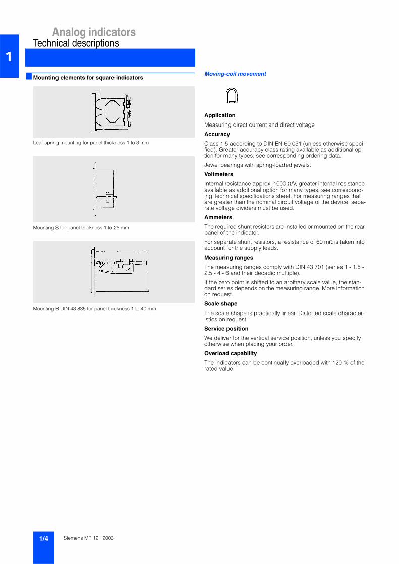
Mounting elements for square indicatorsLeaf-spring mounting for panel thickness 1 to 3 mm
Mounting S for panel thickness 1 to 25 mm
Mounting B DIN 43 835 for panel thickness 1 to 40 mm
Moving-coil movement
Application
Measuring direct current and direct voltage
Accuracy
Class 1.5 according to DIN EN 60 051 (unless otherwise speci-fied). Greater accuracy class rating available as additional op-tion for many types, see corresponding ordering data.
Jewel bearings with spring-loaded jewels.
Voltmeters
Internal resistance approx. 1000 Ω/V, greater internal resistance available as additional option for many types, see correspond-ing Technical specifications sheet. For measuring ranges that are greater than the nominal circuit voltage of the device, sepa-rate voltage dividers must be used.
Ammeters
The required shunt resistors are installed or mounted on the rear panel of the indicator.
For separate shunt resistors, a resistance of 60 mΩ is taken into account for the supply leads.
Measuring ranges
The measuring ranges comply with DIN 43 701 (series 1 - 1.5 - 2.5 - 4 - 6 and their decadic multiple).
If the zero point is shifted to an arbitrary scale value, the stan-dard series depends on the measuring range. More information on request.
Scale shape
The scale shape is practically linear. Distorted scale character-istics on request.
Service position
We deliver for the vertical service position, unless you specify otherwise when placing your order.
Overload capability
The indicators can be continually overloaded with 120 % of the rated value.
Siemens MP 12 · 20031/4

Analog indicatorsTechnical descriptions
1
Moving-iron movementApplication
Moving-iron indicators are primarily used for alternating current and alternating voltage measurements in the usual technical fre-quency range of 15 to 65 Hz. When measuring direct voltages or direct currents, there is usually a 1 % increase in errors. Special designs are available which also comply with the accuracy class rating for zero-frequency and periodic quantities.
Moving-iron indicators show the r.m.s. value of the alternating current and its virtual value; they therefore supply indications, which are independent of curve shape and the harmonic content of the current within specific limits. In the case of extreme curve shapes (e.g. pulse run control, generalized phase control) and extreme frequencies, the accuracy class rating is likely to be ex-ceeded for ammeters (saturation of the iron core) and voltmeters (inductance of the field coil). In such cases, please contact us with further details (special designs possible). Due to their spring-loaded toe bearing, our moving-iron indicators are me-chanically very robust, have high thermal and dynamic overload capabilty and provide outstanding magnetic damping. They therefore offer a solution for a wide range of measuring tasks in the field of heavy current metrology.
Measuring ranges
The measuring ranges comply with DIN 43 701 (series 1 - 1.5 - 2.5 - 4 - 6 and their decadic multiple).
Scale shape
The scale graduation starts at approx. a fifth of the full-scale reading.
If required, ammeters can be supplied with overload scales for double overload, some types even for quadruple overload.
Example:Current transformer 250/5 AAmmeter Display range 0 to 500 A
Measuring range 50 to 250 A
Accuracy
The accuracy of our moving-iron indicators corresponds to Class 1.5 according to DIN EN 60 051. In the case of individual types, the specified accuracy class rating applies.
Greater accuracy class rating available as additional option for many types, see corresponding Technical specifications sheet.
The specified accuracy only applies to the measuring range marked by points on the scale.
Frequency influence
Our moving-iron indicators for alternating current are calibrated at 50 Hz and maintain the accuracy class rating between 15 and 65 Hz. For a surcharge, we can also supply these indicators with a higher nominal frequency (up to 1000 Hz), see corresponding ordering data.
Power consumption
Voltmeters:depending on measuring range, approx. 0.9 to 2.5 VA
Ammeters:depending on measuring range, approx. 0.1 to 1.6 VA
Service position
We deliver for the vertical service position, unless you specify otherwise when placing your order.
Overload capability
The overload capability of our moving-iron indicators corre-sponds to DIN EN 60 051, i.e. they can be continuously over-loaded by 20 % of the rated current or rated voltage.
However, many types have considerably higher overload capa-bilities.
Ammeters:50-fold approx. 1 s4-fold approx. 2 to 3 min.2-fold approx. 10 min.
Voltmeters:2-fold approx. 1 min.
Connection
AC indicators can be connected directly over transformers (please specify rated transformation ratio).
DC indicators are designed for direct connection.
Ammeters ≥ 40 A are calibrated over supply cable leadouts at the side.
Siemens MP 12 · 2003 1/5

Analog indicatorsTechnical descriptions
1
Bimetal movementsApplication
Bimetal ammeters are ideally suited for monitoring the thermal load of cables and transformers.
They have thermal inertia and display the average r.m.s. value. Short-time current peaks have no influence on the measurement result, while continuous loads result in indication. The high torque of the instruments is approx. one thousand times greater than that of other measuring systems, so that the system pointer is also able to drive a slave pointer.
The slave pointer remains at the maximum value reached, which allows conclusions to be drawn on critical points of the supply networks, and can be subsequently read at any time. A sealable reset knob allows the red slave pointer in our bimetal ammeters to be reset to the position of the measuring system pointer.
As well as these measuring instruments with mean value and maximum indication, we also supply bimetal ammeters com-bined with a moving-iron movement for displaying the instanta-neous value.
MAqs. types with both measuring systems mounted diagonally opposite each other in one device and with minimum mounting depth.
Measuring ranges
The full-scale reading for bimetal ammeters and combined mov-ing-iron bimetal ammeters is 1 A or 5 A, maximum scale value is 1.2 or 6 A.
As an additional option, the moving-iron movement is also avail-able for 2-fold overload (i.e. full-scale reading 1 A or 5 A, maxi-mum scale value 2 A or 10 A) available.
When ordering, please specify the transformer rated currents according to DIN 42 600.
Accuracy
Indication error for the red slave pointer of the bimetal move-ments is max. 3 % of full-scale reading; for the moving-iron movement, Class 1.5 according to DIN EN 60 051.
Frequency range
15 to 65 Hz for moving-iron movements
Power consumption(bimetal movementor bimetal-plus moving-iron movement)
Secondary 1 A Mqs. approx. 1.1 VA,MAqs. approx. 1.35 VA
Secondary 5 A Mqs. approx. 1.9 VA,MAqs. approx. 2.2 VA
Service position
We deliver for the vertical service position, unless you specify otherwise when placing your order.
Overload capability
10-fold for 1 s
In the case of greater overloads, a protective current transformer must be connect in series to protect the bimetal movement, thus permitting a 50-fold or 100-fold overload for 1 s. The separate protective current transformer is calibrated together with the bi-metal movement and is not replaceable.
Thermal time lag (setting time)
15 min. (8 min. on request)
Diagram of connections for MAqs types
Bimetal moving-iron movement
Bimetal moving-iron movement with separate protective current trans-former
Bimetal moving-iron movement with integral protective current trans-former
Siemens MP 12 · 20031/6

Analog indicatorsRectangular indicators for direct current or voltage
96 x 48 mm and 48 x 96 mmwith moving-coil movement 1
Analog indicators Pfn 96 x 48
Overview
Input variables7 Direct current7 Direct voltage
Design
The analog indicator comprises:• Moving-coil movement with jewel bearings• Sizes of housing
- 96 x 48 mm (transverse version)- 48 x 96 mm (upright version)
• Polycarbonate housing suitable for- Control panel according to DIN 43 700- Slots
• Replaceable bezel and glass
Electrical connection is over tab connector.
Technical specifications
Display
Scale graduation Coarse-fine
Pointer Beam pointer with knife-edge
Scale length 65 mm
Input DC measuring range corre-sponding to the ordering data
Measuring range Internal resistance Ri (± 20 %)• 100 µA 7000 Ω• 150 µA 4667 Ω• 250 µA 2800 Ω• 400 µA 1750 Ω• 600 µA 1167 Ω
Measuring range Internal resistance Ri (± 20 %)• 1 mA 350 Ω• 1.5 mA 233 Ω• 2 mA 175 Ω• 2.5 mA 140 Ω• 4 mA 80 Ω• 5 mA 70 Ω• 6 mA 58 Ω• 10 mA 35 Ω• 15 mA 23 Ω• 0/4 to 20 mA 18 Ω• 25 mA 14 Ω• ≥ 60 mV to ≤ 250mV 2.5 kΩ/V• > 250 mV 1 kΩ/V
Voltage drop at• > 25 mA to < 1 A 350 mV (± 20 %)• ≥ 1 A 100 mV (± 20 %)
Power consumption if connected to shunt resistor
6 mA (± 20 %)
Error limits
Class 1.5
Housing Polycarbonate, self-extinguishing and drip-proof according to UL 94 V - 0
Front dimensions• Transverse version 96 mm x 48 mm• Upright version 48 mm x 96 mm
Bezel, matt Black (standard),gray (RAL 7037),light gray (RAL 7035),pebble gray (RAL 7032) ordark beige (e.g. RAL 1019)
Mounting depth, without electrical connection
Max. 126 mm
Panel cutout• Transverse version 92+0.8 mm x 45+0.6 mm• Upright version 45+0.6 mm x 92+0.8 mm
Weight Approx. 0.45 kg
Mounting Screw spindle for panel thickness 1 to 40 mm
Electric connection Tab connector 6.3 x 0.8 or 2 x 2, 8 x 0.8 (degree of protection IP 20)
Shock protection Available as optional extra
Reference conditions
Ambient temperature 23 °C ± 2 K
Service position Vertical nominal position ± 1°
Other DIN EN 60 051
Regulations
Nominal circuit voltage 660 V
Degree of protection• Housing front IP 52 according to EN 60 529• Connections IP 20 according to EN 60 529
Siemens MP 12 · 2003 1/7

Analog indicators
96 x 48 mm and 48 x 96 mmwith moving-coil movement
Rectangular indicators for direct current or voltage1
1) Specifications in plain text. 2) Available as type Pf2S5 on request.3) Additional one-off engraving costs on request.
Selection and ordering data Order No. Order Code
Analog indicator 96 x 48 and 48 x 96 with moving-coil movementMeasurement input direct current and direct voltage
M0 1 5 9 4 -
P7777 777
Input variable
• 0 to 20 mA 1 2 6 0
• 4 to 20 mA, mechanically suppressed 9 2 7 0
• Input in the ranges: 9 9 9 9 - Z Y 0 6 1)
- 100 µA to 60 mA- Shunt resistor 60 mV or
150 mV, rated current 1 A to 10 kA- 60 mV to 600 V- Other inputs on request
Additional designsAvailable for all Order Nos. - max. 1 add-on per group. Supplement Order No. with -Z and order code
M0 1 5 9 4 -
P7777 777
Device type
Format• Transverse version - Z H 0 1• Upright version - Z H 0 2
Measuring instrument models
Zero point• Zero point on the left for transverse version
(standard) orZero point at the bottom for upright version (standard)
• Zero point in center - Z N 3 0• Zero point optionally positioned - Z N 0 1 1)
• Zero point on the left, mechanically sup-pressed (not 4 to 20 mA) (max. suppression 20 %; measuring ranges ≥ 250 µA/≥ 250 mV, Ri 1 kΩ/V) (only if ordered together with Order No. H01)
- Z N 4 1 1)
• Zero point on the bottom , mechanically sup-pressed (not 4 to 20 mA) (max. suppression 20 %; measuring ranges ≥ 250 µA/≥ 250 mV, Ri 1 kΩ/V) (only if ordered together with Order No. H02)
- Z N 4 3 1)
Internal resistance for voltmeters• Standard• Ri approx. 10 kΩ/V
(measurement input ≥ 5 V/≤ 150 V)- Z R 0 3
Adjusting potentiometer for voltmeters• Without adjusting potentiometer (standard)• With adjusting potentiometer
Control range ± 15 % (measurement input ≥ 6 V/≤ 400 V; only Class 1.5; power consumption approx. 100 µA)
- Z J 0 1
Lead resistance if connected to shunt resistors ... A/60 mV and ... A/150 mV• 0.06 Ω (standard)• Deviating from 0.06 Ω, limit values:
... A/60 mV in Class 1.5 max. 1 Ω
... A/150 mV in Class 1.5 max. 7 Ω
- Z Z 2 6 1)
Service position• Vertical (standard)• Horizontal - Z G 2 1• Other service position
(specify angle of scale surface from horizontal in plain text)
- Z G 2 4 1)
Selection and ordering data Order No. Order Code
Additional designsAvailable for all Order Nos. - max. 1 add-on per group. Supplement Order No. with -Z and order code
M0 1 5 9 4 -
P7777 777
Measuring instrument models
Special requirements• Normal vibration and impact resistance
(standard)• Available for marine applications with the
following certifications:- Germanischer Lloyd - Z N 9 7 2)
- Vibration resistance 2.5 g; impact resistance 30 g
- Z S 2 0
Scale versions
Scale• Same as measurement input (standard)• Blank scale (start/center/end mark, logo,
symbols)- Z B 8 0
Scale graduation (different to measurement input)• Linear scale - Z Y 0 6 1)
• Scale per curve - Z S 2 6 1)
Graduation and pointer• Single graduation (standard)• Double graduation - Z D 3 1
Additional imprint• Second numbering - Z S 0 5 1)
• Lettering- Without additional lettering (standard)- Lettering ≤ 15 characters German - Z S 0 2 1)
- Lettering > 15 characters German - Z S 1 0 1)
- Lettering ≤ 15 characters foreign language(using Latin lettering)
- Z S 1 2 1)
- Lettering > 15 characters foreign language(using Latin lettering)
- Z S 1 1 1)
Color marking• Colored mark, red RAL 2002 - Z F 2 1 1)
• Colored field, yellow RAL 1021, green RAL 6018 or red RAL 2002
- Z F 2 2 1)
Scale and pointer colors• Scale, white; printing and pointer black
(standard)• Scale, black; printing and pointer white - Z S 5 2 3)
• Scale, black; printing and pointer yellow - Z S 5 3 3)
• Scale, black; printing white, pointer yellow - Z S 5 4 3)
Lighting• Without lighting (standard)• With lighting (direct)
(plexiscale, scale and lighting white)(must be supplemented with Order No. B78 or B79 )
- Z B 5 0
Lamp voltage for lighting• 24 V - Z B 7 8• 28 V - Z B 7 9
Housing models
Field of application• Standard• Conditionally tropic-proof - Z B 1 6
Siemens MP 12 · 20031/8
Analog indicatorsRectangular indicators for direct current or voltage
96 x 48 mm and 48 x 96 mmwith moving-coil movement 1
1) Specifications in plain text.
Dimension drawings
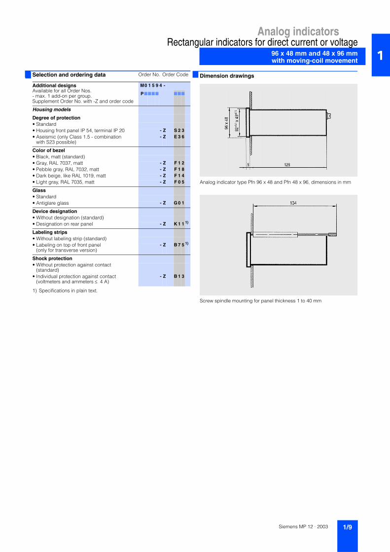
Analog indicator type Pfn 96 x 48 and Pfn 48 x 96, dimensions in mm
Screw spindle mounting for panel thickness 1 to 40 mm
Selection and ordering data Order No. Order Code
Additional designsAvailable for all Order Nos. - max. 1 add-on per group. Supplement Order No. with -Z and order code
M0 1 5 9 4 -
P7777 777
Housing models
Degree of protection• Standard• Housing front panel IP 54, terminal IP 20 - Z S 2 3• Aseismic (only Class 1.5 - combination
with S23 possible)- Z E 3 6
Color of bezel• Black, matt (standard)• Gray, RAL 7037, matt - Z F 1 2• Pebble gray, RAL 7032, matt - Z F 1 8• Dark beige, like RAL 1019, matt - Z F 1 4• Light gray, RAL 7035, matt - Z F 0 5
Glass• Standard• Antiglare glass - Z G 0 1
Device designation• Without designation (standard)• Designation on rear panel - Z K 1 1 1)
Labeling strips• Without labeling strip (standard)• Labeling on top of front panel
(only for transverse version)- Z B 7 5 1)
Shock protection• Without protection against contact
(standard)• Individual protection against contact
(voltmeters and ammeters ≤ 4 A)- Z B 1 3
Siemens MP 12 · 2003 1/9

Analog indicators
144 x 72 mm and 72 x 144 mmwith moving-coil movement
Rectangular indicators for direct current or voltage1
Analog indicator Pf 144 x 72
Overview
Input variables7 Direct current7 Direct voltage
Design
The analog indicator comprises:• Moving-coil movement with jewel bearings• Sizes of housing
- 144 x 72 mm (transverse version)- 72 x 144 mm (upright version)
• Sheet-steel housing suitable for- Control panel according to DIN 43 700- Slots
• Replaceable bezel and glass
Electrical connection is over tab connector
Technical specifications
Display
Scale graduation Coarse-fine
Pointer Beam pointer with knife-edge
Scale length 96 mm
Input DC measuring range corre-sponding to the ordering data
Measuring range Internal resistance Ri (± 20 %)• 100 µA 2000 Ω• 150 µA 2000 Ω• 250 µA 1080 Ω• 400 µA 497 Ω• 600 µA 163 Ω
Measuring range Internal resistance Ri (± 20 %)• 1 mA 69 Ω• 1.5 mA 26.5 Ω• 2 mA 20 Ω• 2.5 mA 10.8 Ω• 4 mA 7.1 Ω• 5 mA 5.8 Ω• 6 mA 2.4 Ω• 10 mA 1.6 Ω• 15 mA 4 Ω• 0/4 to 20 mA 3 Ω• 25 mA 2.4 Ω• ≥ 60 mV to ≤ 250mV 1 kΩ/V• > 250 mV 1 kΩ/V
Voltage drop at• > 25 mA to < 1 A 60 mV (± 20 %)• ≥ 1 A 60 mV (± 20 %)
Power consumption if connected to shunt resistor
6 mA (± 20 %)
Error limits
Class 1.5
Housing Sheet steel housing
Front dimensions• Transverse version 144 mm x 72 mm• Upright version 72 mm x 144 mm
Bezel, matt Black (standard),gray (RAL 7037),light gray (RAL 7035),pebble gray (RAL 7032) ordark beige (e.g. RAL 1019)
Mounting depth, without electrical connection
Max. 168 mm
Panel cutout• Transverse version 138+1 mm x 68+0.7 mm• Upright version 68+0.7 mm x 138+1 mm
Weight Approx. 1.0 kg
Mounting Mounting C DIN 43 835 for panel thickness 1 to 40 mm
Electric connection Terminal clamp M 5
Shock protection Available as optional extra
Reference conditions
Ambient temperature 23 °C ± 2 K
Service position Vertical nominal position ± 1°
Other DIN EN 60 051
Regulations
Nominal circuit voltage 660 V
Degree of protection• Housing front IP 50 according to EN 60 529• Connections IP 00 according to EN 60 529
Siemens MP 12 · 20031/10
Analog indicatorsRectangular indicators for direct current or voltage
144 x 72 mm and 72 x 144 mmwith moving-coil movement 1
1) Specifications in plain text. 2) 0 to 1 mA, 0 to 20 mA, 4 to 20 mA, ≥ 1.5 V.3) Additional one-off engraving costs on request.
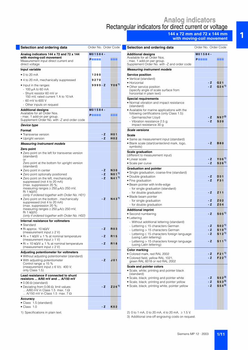
Selection and ordering data Order No. Order Code
Analog indicators 144 x 72 and 72 x 144 with moving-coil movementMeasurement input direct current and direct voltage
M0 1 5 8 4 -
P7777 777
Input variable
• 0 to 20 mA 1 2 6 0
• 4 to 20 mA, mechanically suppressed 9 2 7 0
• Input in the ranges: 9 9 9 9 - Z Y 0 6 1)
- 100 µA to 60 mA- Shunt resistor 60 mV or
150 mV, rated current 1 A to 10 kA- 60 mV to 600 V- Other inputs on request
Additional designsAvailable for all Order Nos. - max. 1 add-on per group. Supplement Order No. with -Z and order code
M0 1 5 8 4 -
P7777 777
Device type
Format• Transverse version - Z H 0 1• Upright version - Z H 0 2
Measuring instrument models
Zero point• Zero point on the left for transverse version
(standard) orZero point at the bottom for upright version (standard)
• Zero point in center - Z N 3 0• Zero point optionally positioned - Z N 0 1 1)
• Zero point on the left, mechanically suppressed (not 4 to 20 mA) (max. suppression 20 %; measuring ranges ≥ 250 µA/≥ 250 mV, Ri 1 kΩ/V)(only if ordered together with Order No. H01)
- Z N 4 1 1)
• Zero point on the bottom , mechanically suppressed (not 4 to 20 mA) (max. suppression 20 %; measuring ranges ≥ 250 µA/≥ 250 mV, Ri 1 kΩ/V) (only if ordered together with Order No. H02)
- Z N 4 3 1)
Internal resistance for voltmeters• Standard• Ri approx. 10 kΩ/V
(measurement input ≥ 2 V)- Z R 0 3
• Ri = 1 kΩ/V ± 1 % at nominal temperature(measurement input ≥ 1 V)
- Z R 1 5
• Ri = 10 kΩ/V ± 1 % at nominal temperature(measurement input ≥ 2 V)
- Z R 1 8
Adjusting potentiometer for voltmeters• Without adjusting potentiometer (standard)• With adjusting potentiometer
Control range ± 15 % (measurement input ≥ 6 V/≤ 400 V; only Class 1.5)
- Z J 0 1
Lead resistance if connected to shunt resistors ... A/60 mV and ... A/150 mV• 0.06 Ω (standard)• Deviating from 0.06 Ω, limit values:
... A/60 mV in Class 1.5 max. 1 Ω
... A/150 mV in Class 1.5 max. 7 Ω
- Z Z 2 6 1)
Accuracy• Class 1.5 (standard)• Class 1.0 - Z K 0 2
Selection and ordering data Order No. Order Code
Additional designsAvailable for all Order Nos. - max. 1 add-on per group. Supplement Order No. with -Z and order code
M0 1 5 8 4 -
P7777 777
Measuring instrument models
Service position• Vertical (standard)• Horizontal - Z G 2 1• Other service position
(specify angle of scale surface from horizontal in plain text)
- Z G 2 4 1)
Special requirements• Normal vibration and impact resistance
(standard)• Available for marine applications with the
following certifications (only Class 1.5):- Germanischer Lloyd - Z N 9 7 2)
- Vibration resistance 2.5 g; impact resistance 30 g
- Z S 2 0
Scale versions
Scale• Same as measurement input (standard)• Blank scale (start/center/end mark, logo,
symbols)- Z B 8 0
Scale graduation (different to measurement input)• Linear scale - Z Y 0 6 1)
• Scale per curve - Z S 2 6 1)
Graduation and pointer• Single graduation, coarse-fine (standard)• Double graduation - Z D 3 1• Fine graduation - Z F 3 1• Beam pointer with knife-edge
- for single graduation (standard)- for double graduation - Z Z 1 1
• Blade beam pointer- for single graduation - Z Z 0 2- for double graduation - Z Z 0 4
Additional imprint• Second numbering - Z S 0 5 1)
• Lettering- Without additional lettering (standard)- Lettering ≤ 15 characters German - Z S 0 2 1)
- Lettering > 15 characters German - Z S 1 0 1)
- Lettering ≤ 15 characters foreign language(using Latin lettering)
- Z S 1 2 1)
- Lettering > 15 characters foreign language(using Latin lettering)
- Z S 1 1 1)
Color marking• Colored mark, red RAL 2002 - Z F 2 1 1)
• Colored field, yellow RAL 1021, green RAL 6018 or red RAL 2002
- Z F 2 2 1)
Scale and pointer colors• Scale, white; printing and pointer black
(standard)• Scale, black; printing and pointer white - Z S 5 2 3)
• Scale, black; printing and pointer yellow - Z S 5 3 3)
• Scale, black; printing white, pointer yellow - Z S 5 4 3)
Siemens MP 12 · 2003 1/11

Analog indicators
144 x 72 mm and 72 x 144 mmwith moving-coil movement
Rectangular indicators for direct current or voltage1
1) Additional one-off engraving costs on request.2) Specifications in plain text.3) Not on bottom for transverse version.
Dimension drawings
Analog indicators type Pf 144 x 72 and Pf 72 x 144, dimensions in mm
Mounting C DIN 43 835 for panel thickness 1 to 40 mm
Selection and ordering data Order No. Order Code
Additional designsAvailable for all Order Nos. - max. 1 add-on per group. Supplement Order No. with -Z and order code
M0 1 5 8 4 -
P7777 777
Scale versions
Lighting• Without lighting (standard)• With lighting (direct)
(plexiscale, scale and lighting white)(must be supplemented with Order No. B78 or B79 )
- Z B 5 0
• Optical fiber with mask, lighting white - Z B 7 3 1)
• Optical fiber with mask, lighting red (must be supplemented with Order No. (S52, S53 or S54) and (B78 or B79))
- Z B 7 4 1)
Lamp voltage for lighting• 24 V - Z B 7 8• 28 V - Z B 7 9
Housing models
Field of application• Standard• Conditionally tropic-proof - Z B 1 6
Degree of protection• Standard• Housing front panel IP 54, terminal IP 00 - Z S 2 2• Aseismic (only Class 1.5 - combination with
S22 possible)- Z E 3 6
Color of bezel• Black, matt (standard)• Gray, RAL 7037, matt - Z F 1 2• Pebble gray, RAL 7032, matt - Z F 1 8• Dark beige, like RAL 1019, matt - Z F 1 4• Light gray, RAL 7035, matt - Z F 0 5
Glass• Standard• Antiglare glass - Z G 0 1
Device designation• Without designation (standard)• Designation on rear panel - Z K 1 1 2)
Labeling strips• Without labeling strip (standard)• Labeling on top or bottom of front panel - Z B 7 5 2)
3)
Shock protection• Without protection against contact
(standard)• Individual protection against contact
(voltmeters and ammeters ≤ 4 A)- Z B 1 3
Siemens MP 12 · 20031/12

Analog indicatorsSquare indicators for direct current or voltage
72 x 72 mmwith moving-coil movement 1
Analog indicator V-Pqs 72
Overview
Input variables7 Direct current7 Direct voltage
Design
The analog indicator comprises:• Moving-coil movement with jewel bearings• Housing size 72 x 72 mm• Polycarbonate housing suitable for
- Control panel according to DIN 43 700- Slots
• Replaceable bezel and glass• The indicator has an interchangeable scale
Electrical connection is over screw terminals.
Technical specifications
Display
Scale graduation Coarse-fine
Pointer Beam pointer with knife-edge
Scale length 66 mm
Interchangeable scale Yes
Input DC measuring range corre-sponding to the ordering data
Measuring range Internal resistance Ri• 100 µA 1943 Ω (± 20 %)• 150 µA 1547 Ω (± 20 %)• 250 µA 1233 Ω (± 20 %)• 400 µA 375 Ω (± 20 %)• 600 µA 202 Ω (± 20 %)
Measuring range Internal resistance Ri• 1 mA 79 Ω (± 20 %)• 1.5 mA 37.5 Ω (± 20 %)• 2 mA 21 Ω (± 20 %)• 2.5 mA 11.4 Ω (± 20 %)• 4 mA 6.7 Ω (± 30 %)• 5 mA 4.8 Ω (± 30 %)• 6 mA 3 Ω (± 30 %)• 10 mA 3.4 Ω (± 30 %)• 15 mA 4 Ω (± 30 %)• 0/4 to 20 mA 3 Ω (± 30 %)• 25 mA 2.4 Ω (± 30 %)• ≥ 60 mV 1 kΩ/V
Voltage drop at• > 25 mA 60 mV (± 20 %)
Power consumption if connected to shunt resistor
6 mA (± 20 %)
Error limits
Class 1.5
Housing Polycarbonate, self-extinguishing and drip-proof according to UL 94 V - 0Sheet-steel housing available as optional extra.
Front dimensions 72 mm x 72 mm
Bezel, matt Black (standard),gray (RAL 7037),light gray (RAL 7035),pebble gray (RAL 7032) ordark beige (e.g. RAL 1019)
Mounting depth, without electrical connection
43.5 mm,62.5 mm at BV 3340 of Federal Navy (Order No. N98)
Panel cutout 68+0.7 mm x 68+0.7 mm
Weight Approx. 0.2 kg
Mounting Mounting S for panel thickness 1 to 25 mm
Electric connection M4 (voltmeters & ammeters ≤ 4 A) or M6 (ammeters > 4 A).Screw terminals M 4 with self-lift-ing clamps; Screws suitable for Philips and normal screwdrivers.
Shock protection Available as optional extra
Reference conditions
Ambient temperature 23 °C ± 2 K
Service position Vertical nominal position ± 1°
Other DIN EN 60 051
Regulations
Nominal circuit voltage 1000 V
Degree of protection• Housing front IP 52 according to EN 60 529• Connections IP 00 according to EN 60 529
Siemens MP 12 · 2003 1/13
Analog indicators
72 x 72 mmwith moving-coil movement
Square indicators for direct current or voltage1
1) Specifications in plain text. 2) Contains sheet-steel housing with cone-head rivets (Order No. M40) and mounting B (Order No. B22).
3) The type is different in Pqs 72 and the Order No. in M01614-P.
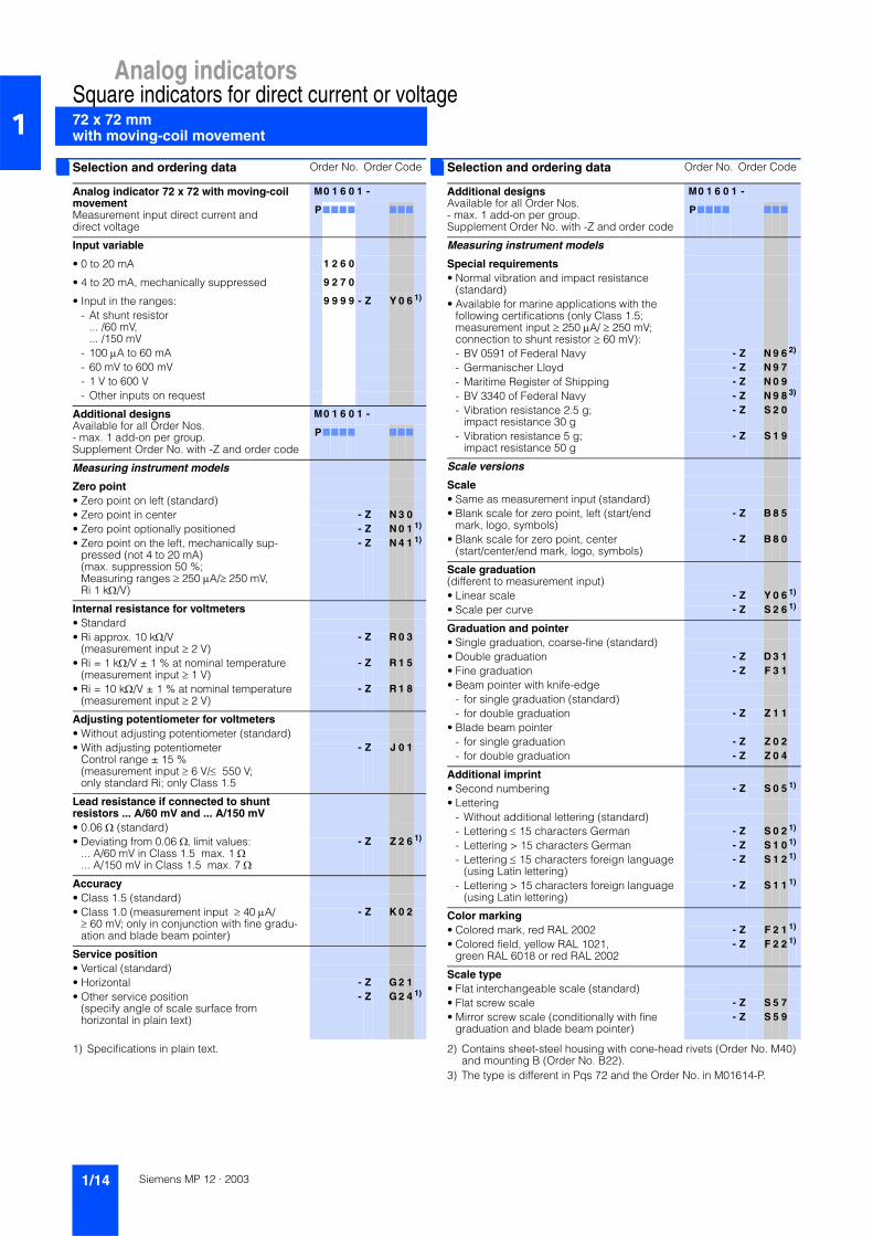
Selection and ordering data Order No. Order Code
Analog indicator 72 x 72 with moving-coil movementMeasurement input direct current and direct voltage
M0 1 6 0 1 -
P7777 777
Input variable
• 0 to 20 mA 1 2 6 0
• 4 to 20 mA, mechanically suppressed 9 2 7 0
• Input in the ranges: 9 9 9 9 - Z Y 0 6 1)
- At shunt resistor ... /60 mV, ... /150 mV
- 100 µA to 60 mA- 60 mV to 600 mV- 1 V to 600 V- Other inputs on request
Additional designsAvailable for all Order Nos. - max. 1 add-on per group. Supplement Order No. with -Z and order code
M0 1 6 0 1 -
P7777 777
Measuring instrument models
Zero point• Zero point on left (standard)• Zero point in center - Z N 3 0• Zero point optionally positioned - Z N 0 1 1)
• Zero point on the left, mechanically sup-pressed (not 4 to 20 mA) (max. suppression 50 %; Measuring ranges ≥ 250 µA/≥ 250 mV, Ri 1 kΩ/V)
- Z N 4 1 1)
Internal resistance for voltmeters• Standard• Ri approx. 10 kΩ/V
(measurement input ≥ 2 V)- Z R 0 3
• Ri = 1 kΩ/V ± 1 % at nominal temperature(measurement input ≥ 1 V)
- Z R 1 5
• Ri = 10 kΩ/V ± 1 % at nominal temperature(measurement input ≥ 2 V)
- Z R 1 8
Adjusting potentiometer for voltmeters• Without adjusting potentiometer (standard)• With adjusting potentiometer
Control range ± 15 % (measurement input ≥ 6 V/≤ 550 V; only standard Ri; only Class 1.5
- Z J 0 1
Lead resistance if connected to shunt resistors ... A/60 mV and ... A/150 mV• 0.06 Ω (standard)• Deviating from 0.06 Ω, limit values:
... A/60 mV in Class 1.5 max. 1 Ω
... A/150 mV in Class 1.5 max. 7 Ω
- Z Z 2 6 1)
Accuracy• Class 1.5 (standard)• Class 1.0 (measurement input ≥ 40 µA/
≥ 60 mV; only in conjunction with fine gradu-ation and blade beam pointer)
- Z K 0 2
Service position• Vertical (standard)• Horizontal - Z G 2 1• Other service position
(specify angle of scale surface from horizontal in plain text)
- Z G 2 4 1)
Selection and ordering data Order No. Order Code
Additional designsAvailable for all Order Nos. - max. 1 add-on per group. Supplement Order No. with -Z and order code
M0 1 6 0 1 -
P7777 777
Measuring instrument models
Special requirements• Normal vibration and impact resistance
(standard)• Available for marine applications with the
following certifications (only Class 1.5; measurement input ≥ 250 µA/ ≥ 250 mV; connection to shunt resistor ≥ 60 mV):- BV 0591 of Federal Navy - Z N 9 6 2)
- Germanischer Lloyd - Z N 9 7- Maritime Register of Shipping - Z N 0 9- BV 3340 of Federal Navy - Z N 9 8 3)
- Vibration resistance 2.5 g; impact resistance 30 g
- Z S 2 0
- Vibration resistance 5 g; impact resistance 50 g
- Z S 1 9
Scale versions
Scale• Same as measurement input (standard)• Blank scale for zero point, left (start/end
mark, logo, symbols)- Z B 8 5
• Blank scale for zero point, center (start/center/end mark, logo, symbols)
- Z B 8 0
Scale graduation (different to measurement input)• Linear scale - Z Y 0 6 1)
• Scale per curve - Z S 2 6 1)
Graduation and pointer• Single graduation, coarse-fine (standard)• Double graduation - Z D 3 1• Fine graduation - Z F 3 1• Beam pointer with knife-edge
- for single graduation (standard)- for double graduation - Z Z 1 1
• Blade beam pointer- for single graduation - Z Z 0 2- for double graduation - Z Z 0 4
Additional imprint• Second numbering - Z S 0 5 1)
• Lettering- Without additional lettering (standard)- Lettering ≤ 15 characters German - Z S 0 2 1)
- Lettering > 15 characters German - Z S 1 0 1)
- Lettering ≤ 15 characters foreign language(using Latin lettering)
- Z S 1 2 1)
- Lettering > 15 characters foreign language(using Latin lettering)
- Z S 1 1 1)
Color marking• Colored mark, red RAL 2002 - Z F 2 1 1)
• Colored field, yellow RAL 1021, green RAL 6018 or red RAL 2002
- Z F 2 2 1)
Scale type • Flat interchangeable scale (standard)• Flat screw scale - Z S 5 7• Mirror screw scale (conditionally with fine
graduation and blade beam pointer)- Z S 5 9
Siemens MP 12 · 20031/14

Analog indicatorsSquare indicators for direct current or voltage
72 x 72 mmwith moving-coil movement 1
1) Additional one-off engraving costs on request.
2) Specifications in plain text.
Dimension drawings
Analog indicator type V-Pqs 72, dimensions in mm
Selection and ordering data Order No. Order Code
Additional designsAvailable for all Order Nos. - max. 1 add-on per group. Supplement Order No. with -Z and order code
M0 1 6 0 1 -
P7777 777
Scale versions
Scale and pointer colors• Scale, white; printing and pointer black
(standard)• Scale, black; printing and pointer white - Z S 5 2 1)
• Scale, black; printing and pointer yellow - Z S 5 3 1)
• Scale, black; printing white, pointer yellow - Z S 5 4 1)
• Without scale; pointer, black (only for devices for connection to transducers and shunt resistors)
- Z S 6 2
• Without scale; pointer, white(only for devices for connection to transducers and shunt resistors)
- Z S 6 3
• Without scale; pointer, yellow (only for devices for connection to transducers and shunt resistors)
- Z S 6 4
Lighting• Without lighting (standard)• With lighting (direct)
(plexiscale, scale and lighting, white)(must be supplemented with Order No. B77, B78 or B79)
- Z B 5 0
• Optical fiber with mask, lighting white - Z B 7 3 1)
• Optical fiber with mask, lighting red (must be supplemented with Order No. (S52, S53 or S54) and (B77, B78 or B79).lighting only available with flat screw scale (Order No. S57).)
- Z B 7 4 1)
Lamp voltage for lighting• 12 V - Z B 7 7• 24 V - Z B 7 8• 28 V - Z B 7 9
Housing models
Field of application• Standard• Conditionally tropic-proof - Z B 1 6
Degree of protection• Standard• Housing front panel IP 54, terminal IP 00 - Z S 2 2• Aseismic (only Class 1.5 - combination with
S22 possible)- Z E 3 6
Color of bezel• Black, matt (standard)• Gray, RAL 7037, matt - Z F 1 2• Pebble gray, RAL 7032, matt - Z F 1 8• Dark beige, like RAL 1019, matt - Z F 1 4• Light gray, RAL 7035, matt - Z F 0 5
Intermediate frame, 3 mm high• Without intermediate frame (standard)• Intermediate frame, black, gloss
(only in conjunction with mounting S or B)- Z Z 3 1
• Intermediate frame, gray RAL 7037, gloss(only in conjunction with mounting S or B)
- Z Z 3 2
Glass• Standard• Antiglare glass - Z G 0 1
Selection and ordering data Order No. Order Code
Additional designsAvailable for all Order Nos. - max. 1 add-on per group. Supplement Order No. with -Z and order code
M0 1 6 0 1 -
P7777 777
Housing models
Housing• Standard housing (standard housing in con-
junction with mounting B92 also suitable for Mauell and H&B Unibloc slots)
• Sheet-steel housing with cone-head rivets - Z M4 0
Mounting• Mounting S (panel thickness 1 to 25 mm)
(standard)• 2 leaf-springs (panel thickness 1 to 3 mm) - Z B 9 2• 4 leaf-springs (panel thickness 1 to 3 mm) - Z B 2 1• Mounting B (panel thickness 1 to 40 mm)
(only if ordered together with Order No. M40)- Z B 2 2
• Subklew fasteners (mounting S without pivot) - Z B 1 5• Without mounting - Z B 2 3
Device designation• Without designation (standard)• Designation on rear panel - Z K 1 1 2)
Constants indication• Without constant indication (standard)• Constant indication
1-1.5-2-2.5-3-4-5-6-7.5-8-10- Z K 3 5
Adjustable set pointer• Without adjustable set pointer (standard)• 1 adjustable set pointer, red - Z M0 1
Labeling strips• Without labeling strip (standard)• Labeling on the bottom of front panel - Z B 7 5 2)
Shock protection• Without protection against contact
(standard)• Overall protection against contact - Z B 0 8• Individual protection against contact
(voltmeters and ammeters ≤ 4 A)- Z B 1 3
Siemens MP 12 · 2003 1/15
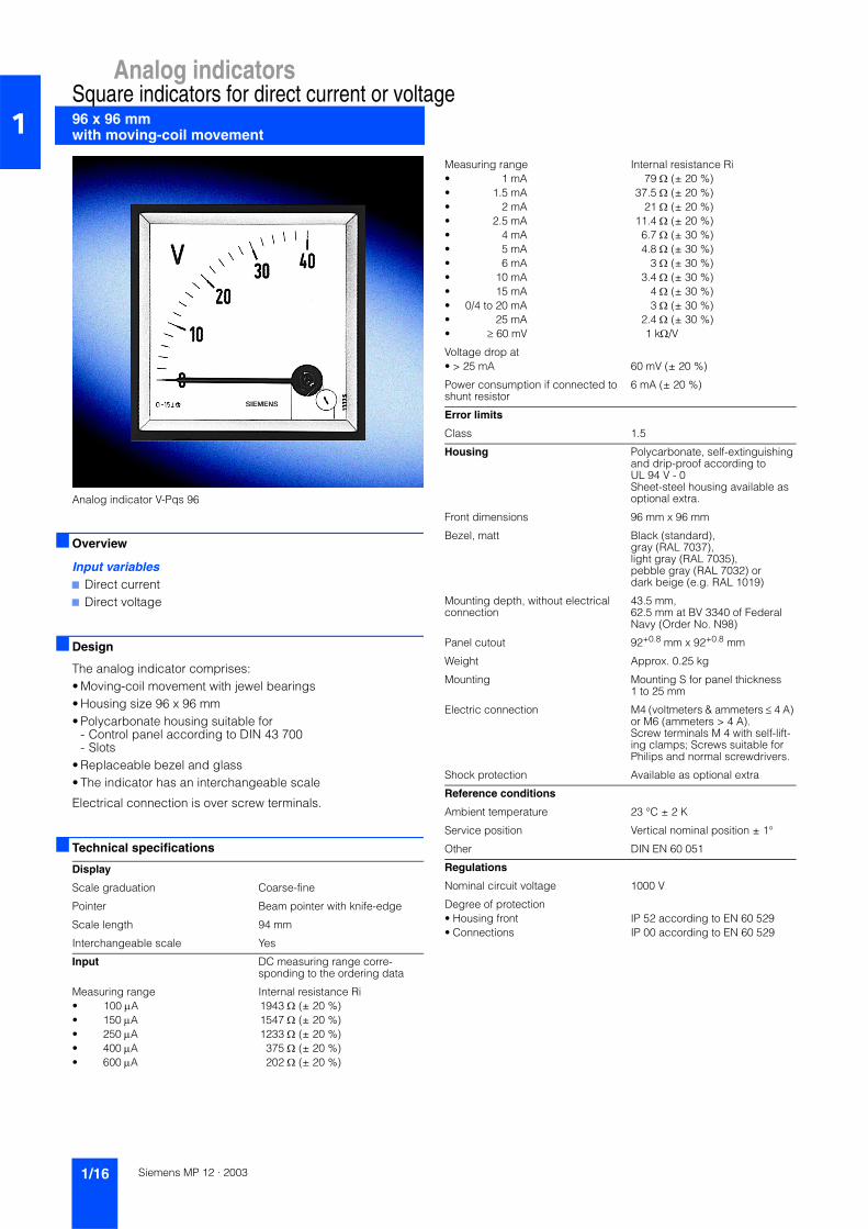
Analog indicators
96 x 96 mm with moving-coil movement
Square indicators for direct current or voltage1
Analog indicator V-Pqs 96
Overview
Input variables7 Direct current7 Direct voltage
Design
The analog indicator comprises:• Moving-coil movement with jewel bearings• Housing size 96 x 96 mm• Polycarbonate housing suitable for
- Control panel according to DIN 43 700- Slots
• Replaceable bezel and glass• The indicator has an interchangeable scale
Electrical connection is over screw terminals.
Technical specifications
Display
Scale graduation Coarse-fine
Pointer Beam pointer with knife-edge
Scale length 94 mm
Interchangeable scale Yes
Input DC measuring range corre-sponding to the ordering data
Measuring range Internal resistance Ri• 100 µA 1943 Ω (± 20 %)• 150 µA 1547 Ω (± 20 %)• 250 µA 1233 Ω (± 20 %)• 400 µA 375 Ω (± 20 %)• 600 µA 202 Ω (± 20 %)
Measuring range Internal resistance Ri• 1 mA 79 Ω (± 20 %)• 1.5 mA 37.5 Ω (± 20 %)• 2 mA 21 Ω (± 20 %)• 2.5 mA 11.4 Ω (± 20 %)• 4 mA 6.7 Ω (± 30 %)• 5 mA 4.8 Ω (± 30 %)• 6 mA 3 Ω (± 30 %)• 10 mA 3.4 Ω (± 30 %)• 15 mA 4 Ω (± 30 %)• 0/4 to 20 mA 3 Ω (± 30 %)• 25 mA 2.4 Ω (± 30 %)• ≥ 60 mV 1 kΩ/V
Voltage drop at• > 25 mA 60 mV (± 20 %)
Power consumption if connected to shunt resistor
6 mA (± 20 %)
Error limits
Class 1.5
Housing Polycarbonate, self-extinguishing and drip-proof according to UL 94 V - 0Sheet-steel housing available as optional extra.
Front dimensions 96 mm x 96 mm
Bezel, matt Black (standard),gray (RAL 7037),light gray (RAL 7035),pebble gray (RAL 7032) ordark beige (e.g. RAL 1019)
Mounting depth, without electrical connection
43.5 mm,62.5 mm at BV 3340 of Federal Navy (Order No. N98)
Panel cutout 92+0.8 mm x 92+0.8 mm
Weight Approx. 0.25 kg
Mounting Mounting S for panel thickness 1 to 25 mm
Electric connection M4 (voltmeters & ammeters ≤ 4 A) or M6 (ammeters > 4 A).Screw terminals M 4 with self-lift-ing clamps; Screws suitable for Philips and normal screwdrivers.
Shock protection Available as optional extra
Reference conditions
Ambient temperature 23 °C ± 2 K
Service position Vertical nominal position ± 1°
Other DIN EN 60 051
Regulations
Nominal circuit voltage 1000 V
Degree of protection• Housing front IP 52 according to EN 60 529• Connections IP 00 according to EN 60 529
Siemens MP 12 · 20031/16

Analog indicatorsSquare indicators for direct current or voltage
96 x 96 mmwith moving-coil movement 1
1) Specifications in plain text. 2) Contains sheet-steel housing with cone-head rivets (Order No. M40) and mounting B (Order No. B22).
3) The type is different in Pqs 96 and the Order No. in M01616-P.
Selection and ordering data Order No. Order Code
Analog indicator 96 x 96 with moving-coil movementMeasurement input direct current anddirect voltage
M0 1 6 0 4 -
P7777 777
Input variable
• 0 to 20 mA 1 2 6 0
• 4 to 20 mA, mechanically suppressed 9 2 7 0
• Input in the ranges: 9 9 9 9 - Z Y 0 6 1)
- At shunt resistor ... /60 mV, ... /150 mV
- 100 µA to 60 mA- 60 mV to 600 mV- 1 V to 600 V- Other inputs on request
Additional designsAvailable for all Order Nos. - max. 1 add-on per group. Supplement Order No. with -Z and order code
M0 1 6 0 4 -
P7777 777
Measuring instrument models
Zero point• Zero point on left (standard)• Zero point in center - Z N 3 0• Zero point optionally positioned - Z N 0 1 1)
• Zero point on the left, mechanically suppressed (not 4 to 20 mA) (max. suppression 50 %; Measuring ranges ≥ 250 µA/≥ 250 mV, Ri 1 kΩ/V)
- Z N 4 1 1)
Internal resistance for voltmeters• Standard• Ri approx. 10 kΩ/V
(measurement input ≥ 2 V)- Z R 0 3
• Ri = 1 kΩ/V ± 1 % at nominal temperature(measurement input ≥ 1 V)
- Z R 1 5
• Ri = 10 kΩ/V ± 1 % at nominal temperature(measurement input ≥ 2 V)
- Z R 1 8
Adjusting potentiometer for voltmeters• Without adjusting potentiometer (standard)• With adjusting potentiometer
Control range ± 15 % (measurement input ≥ 6 V/≤ 550 V; only standard Ri; only Class 1.5
- Z J 0 1
Lead resistance if connected to shunt resistors ... A/60 mV and ... A/150 mV• 0.06 Ω (standard)• Deviating from 0.06 Ω, limit values:
... A/60 mV in Class 1.5 max. 1 Ω
... A/150 mV in Class 1.5 max. 7 Ω
- Z Z 2 6 1)
Accuracy• Class 1.5 (standard)• Class 1.0
(measurement input ≥ 40 mA/≥ 60 mV)- Z K 0 2
Service position• Vertical (standard)• Horizontal - Z G 2 1• Other service position
(specify angle of scale surface from horizontal in plain text)
- Z G 2 4 1)
Selection and ordering data Order No. Order Code
Additional designsAvailable for all Order Nos. - max. 1 add-on per group. Supplement Order No. with -Z and order code
M0 1 6 0 4 -
P7777 777
Measuring instrument models
Special requirements• Normal vibration and impact resistance
(standard)• Available for marine applications with the
following certifications (only Class 1.5; measurement input ≥ 250 µA/ ≥ 250 mV; connection to shunt resistor ≥ 60 mV):- BV 0591 of Federal Navy - Z N 9 6 2)
- Germanischer Lloyd - Z N 9 7- Maritime Register of Shipping - Z N 0 9- BV 3340 of Federal Navy - Z N 9 8 3)
- Vibration resistance 2.5 g; impact resistance 30 g
- Z S 2 0
- Vibration resistance 5 g; impact resistance 50 g
- Z S 1 9
Scale versions
Scale• Same as measurement input (standard)• Blank scale for zero point, left (start/end
mark, logo, symbols)- Z B 8 5
• Blank scale for zero point, center (start/center/end mark, logo, symbols)
- Z B 8 0
Scale graduation (different to measurement input)• Linear scale - Z Y 0 6 1)
• Scale per curve - Z S 2 6 1)
Graduation and pointer• Single graduation, coarse-fine (standard)• Double graduation - Z D 3 1• Fine graduation - Z F 3 1• Beam pointer with knife-edge
- for single graduation (standard)- for double graduation - Z Z 1 1
• Blade beam pointer- for single graduation - Z Z 0 2- for double graduation - Z Z 0 4
Additional imprint• Second numbering - Z S 0 5 1)
• Lettering- Without additional lettering (standard)- Lettering ≤ 15 characters German - Z S 0 2 1)
- Lettering > 15 characters German - Z S 1 0 1)
- Lettering ≤ 15 characters foreign language(using Latin lettering)
- Z S 1 2 1)
- Lettering > 15 characters foreign language(using Latin lettering)
- Z S 1 1 1)
Color marking• Colored mark, red RAL 2002 - Z F 2 1 1)
• Colored field, yellow RAL 1021, green RAL 6018 or red RAL 2002
- Z F 2 2 1)
Scale type • Flat interchangeable scale (standard)• Flat screw scale - Z S 5 7• Mirror interchangeable scale (conditionally
with fine graduation and blade beam pointer)- Z S 5 8
• Mirror screw scale (conditionally with fine graduation and blade beam pointer)
- Z S 5 9
Siemens MP 12 · 2003 1/17

Analog indicators
96 x 96 mm with moving-coil movement
Square indicators for direct current or voltage1
1) Additional one-off engraving costs on request.
2) Specifications in plain text.
Dimension drawings
Analog indicator type V-Pqs 96, dimensions in mm
Selection and ordering data Order No. Order Code
Additional designsAvailable for all Order Nos. - max. 1 add-on per group. Supplement Order No. with -Z and order code
M0 1 6 0 4 -
P7777 777
Scale versions
Scale and pointer colors• Scale, white; printing and pointer black
(standard)• Scale, black; printing and pointer white - Z S 5 2 1)
• Scale, black; printing and pointer yellow - Z S 5 3 1)
• Scale, black; printing white, pointer yellow - Z S 5 4 1)
• Without scale; pointer, black (only for devices for connection to transducers and shunt resistors)
- Z S 6 2
• Without scale; pointer, white(only for devices for connection to transducers and shunt resistors)
- Z S 6 3
• Without scale; pointer, yellow (only for devices for connection to transducers and shunt resistors)
- Z S 6 4
Lighting• Without lighting (standard)• With lighting (direct)
(plexiscale, scale and lighting, white)(must be supplemented with Order No. B77, B78 or B79)
- Z B 5 0
• Optical fiber with mask, lighting white - Z B 7 3 1)
• Optical fiber with mask, lighting red (must be supplemented with Order No. (S52, S53 or S54) and (B77, B78 or B79).lighting only available with flat screw scale (Order No. S57).)
- Z B 7 4 1)
Lamp voltage for lighting• 12 V - Z B 7 7• 24 V - Z B 7 8• 28 V - Z B 7 9
Housing models
Field of application• Standard• Conditionally tropic-proof - Z B 1 6
Degree of protection• Standard• Housing front panel IP 54, terminal IP 00 - Z S 2 2• Aseismic (only Class 1.5 - combination with
S22 possible)- Z E 3 6
Color of bezel• Black, matt (standard)• Gray, RAL 7037, matt - Z F 1 2• Pebble gray, RAL 7032, matt - Z F 1 8• Dark beige, like RAL 1019, matt - Z F 1 4• Light gray, RAL 7035, matt - Z F 0 5
Intermediate frame, 3 mm high• Without intermediate frame (standard)• Intermediate frame, black, gloss
(only in conjunction with mounting S or B)- Z Z 3 1
• Intermediate frame, gray RAL 7037, gloss(only in conjunction with mounting S or B)
- Z Z 3 2
Glass• Standard• Antiglare glass - Z G 0 1
Selection and ordering data Order No. Order Code
Additional designsAvailable for all Order Nos. - max. 1 add-on per group. Supplement Order No. with -Z and order code
M0 1 6 0 4 -
P7777 777
Housing models
Housing• Standard housing(standard housing in con-
junction with mounting B92 also suitable for Mauell and H&B Unibloc slots)
• Sheet-steel housing with cone-head rivets - Z M4 0
Mounting• Mounting S (panel thickness 1 to 25 mm)
(standard)• 2 leaf-springs (panel thickness 1 to 3 mm) - Z B 9 2• 4 leaf-springs (panel thickness 1 to 3 mm) - Z B 2 1• Mounting B (panel thickness 1 to 40 mm)
(only if ordered together with Order No. M40)- Z B 2 2
• Subklew fasteners (mounting S without pivot) - Z B 1 5• Without mounting - Z B 2 3
Device designation• Without designation (standard)• Designation on rear panel - Z K 1 1 2)
Constants indication• Without constant indication (standard)• Constant indication
1-1.5-2-2.5-3-4-5-6-7.5-8-10- Z K 3 5
Adjustable set pointer• Without adjustable set pointer (standard)• 1 adjustable set pointer, red - Z M0 1
Labeling strips• Without labeling strip (standard)• Labeling on the bottom of front panel - Z B 7 5 2)
Shock protection• Without protection against contact
(standard)• Overall protection against contact - Z B 0 8• Individual protection against contact
(voltmeters and ammeters ≤ 4 A)- Z B 1 3
Siemens MP 12 · 20031/18

Analog indicatorsSquare indicators for alternating current or voltage, 15 to 65 Hz
72 x 72 mmwith moving-iron movement 1
Analog indicator V-Aqs 72
Overview
Input variables7 Alternating current 15 to 65 Hz7 Alternating voltage 15 to 65 Hz
Design
The analog indicator comprises:• Moving-iron movement with jewel bearings• Housing size 72 x 72 mm• Polycarbonate housing suitable for
- Control panel according to DIN 43 700- Slots
• Replaceable bezel and glass• The indicator has an interchangeable scale
Electrical connection is over screw terminals.
Technical specifications
Display
Scale graduation Coarse-fine
Pointer Beam pointer with knife-edge
Scale length 66 mm
Interchangeable scale Yes
Input DC measuring range corre-sponding to the ordering data
Power consumption
If connected to voltage transformer• Secondary/100 V (120 V) Approx. 1.0 VA (1.4 VA)• Secondary/110 V (132 V) Approx. 1.4 VA (2.0 VA)
If connected to current transformer• Secondary 1 A Approx. 0.25 VA• Secondary 5 A Approx. 0.30 VA
Error limits
Class 1.5
Housing Polycarbonate, self-extinguishing and drip-proof according to UL 94 V - 0Sheet-steel housing available as optional extra.
Front dimensions 72 mm x 72 mm
Bezel, matt Black (standard),gray (RAL 7037),light gray (RAL 7035),pebble gray (RAL 7032) ordark beige (e.g. RAL 1019)
Mounting depth, without electrical connection
43.5 mm
Panel cutout 68+0.7 mm x 68+0.7 mm
Weight Approx. 0.2 kg
Mounting Mounting S for panel thickness 1 to 25 mm
Electric connection M4 (voltmeter & ammeter ≤ 9 A), M6 (ammeter > 9 A to ≤ 60 A) or M8 (ammeter > 60 A to ≤ 100 A).Screw terminals M 4 with self-lift-ing clamps; Screws suitable for Philips and normal screwdrivers.
Shock protection Available as optional extra
Reference conditions
Ambient temperature 23 °C ± 2 K
Service position Vertical nominal position ± 1°
Other DIN EN 60 051
Regulations
Nominal circuit voltage 1000 V
Degree of protection• Housing front IP 52 according to EN 60 529• Connections IP 00 according to EN 60 529
Siemens MP 12 · 2003 1/19

Analog indicators
72 x 72 mm with moving-iron movement
Square indicators for alternating current or voltage, 15 to 65 Hz1
1) Specifications in plain text.2) Contains sheet-steel housing with cone-head rivets (Order No. M40)
and mounting B (Order No. B22).
3) Additional one-off engraving costs on request.
Selection and ordering data Order No. Order Code
Analog indicator 72 x 72 with moving-iron movementMeasurement input alternating current oralternating voltage
M0 1 6 0 1 -
E7777 777
Input variable• ... A/1 A, connection to current transformer 3 9 9 0 - Z Y 0 6 1)
• ... A/5 A, connection to current transformer 4 9 9 0 - Z Y 0 6 1)
• Input in the ranges: 9 9 9 9 - Z Y 0 6 1)
- 100 mA to 6 A- 6 V to 100 V- Voltage transformer secondary 100 V/110 V
primary ... V- Other inputs on request
Additional designsAvailable for all Order Nos. - max. 1 add-on per group. Supplement Order No. with -Z and order code
M0 1 6 0 1 -
E7777 777
Measuring instrument models
Measurement input• Alternating current/voltage (standard)• Direct current/voltage - Z M5 4• Direct/alternating current and direct/
alternating voltage- Z M5 3
Nominal frequency• 15 to 65 Hz (standard)• ... Hz
(one frequency in the range > 65 to 500 Hz) for voltmeters ≥ 40 V with standard ranges and ammeters ≤ 6 A
- Z N 1 3 1)
• ... Hz (one frequency in the range > 65 to 500 Hz) for ammeters > 6 A
- Z N 1 4 1)
Shielding• Installation conditions, normal (standard)• Increased external field protection - Z F 3 7
Service position• Vertical (standard)• Horizontal - Z G 2 1• Other service position (specify angle of scale
surface from horizontal in plain text)- Z G 2 4 1)
Special requirements• Normal vibration and impact resistance
(standard)• Available for marine applications with the
following certifications (only Class 1.5; Measurement input ≥ 100 mA/≥ 6 V):- BV 0591 of Federal Navy - Z N 9 6 2)
- Germanischer Lloyd - Z N 9 7- Maritime Register of Shipping - Z N 0 9- Vibration resistance 2.5 g;
impact resistance 30 g- Z S 2 0
- Vibration resistance 5 g; impact resistance 50 g
- Z S 1 9
Scale versions
Scale• Same as measurement input (standard)• Blank scale (start/end mark, logo, symbols) - Z B 8 5
Selection and ordering data Order No. Order Code
Additional designsAvailable for all Order Nos. - max. 1 add-on per group. Supplement Order No. with -Z and order code
M0 1 6 0 1 -
E7777 777
Scale versions
Graduation and pointer• Single graduation, coarse-fine (standard)• Double graduation - Z D 3 1• Fine graduation - Z F 3 1• Beam pointer with knife-edge
- for single graduation (standard)- for double graduation - Z Z 1 1
• Blade beam pointer- for single graduation - Z Z 0 2- for double graduation - Z Z 0 4
Additional imprint• Second numbering - Z S 0 5 1)
• Lettering- Without additional lettering (standard)- Lettering ≤ 15 characters German - Z S 0 2 1)
- Lettering > 15 characters German - Z S 1 0 1)
- Lettering ≤ 15 characters foreign language(using Latin lettering)
- Z S 1 2 1)
- Lettering > 15 characters foreign language(using Latin lettering)
- Z S 1 1 1)
Color marking• Colored mark, red RAL 2002 - Z F 2 1 1)
• Colored field, yellow RAL 1021, green RAL 6018 or red RAL 2002
- Z F 2 2 1)
Scale type • Flat interchangeable scale (standard)• Flat screw scale - Z S 5 7
Overload• No overload (standard)• 1.2-fold - Z U 0 1• 2-fold (only for ammeters) - Z U 0 2• 4-fold (only for ammeters;
full-scale reading ≤ 40 A)- Z U 0 3
Scale and pointer colors• Scale, white; printing and pointer black
(standard)• Scale, black; printing and pointer white - Z S 5 2 3)
• Scale, black; printing and pointer yellow - Z S 5 3 3)
• Without scale; Pointer, black (only for devices with connection to current and voltage transformers)
- Z S 6 2
• Without scale; Pointer, white(only for devices with connection to current and voltage transformers)
- Z S 6 3
• Without scale; Pointer, yellow(only for devices with connection to current and voltage transformers)
- Z S 6 4
Lighting• Without lighting (standard)• With lighting (direct)
(plexiscale, scale and lighting, white)(must be supplemented with Order No. B77, B78 or B79)
- Z B 5 0
Siemens MP 12 · 20031/20

Analog indicatorsSquare indicators for alternating current or voltage, 15 to 65 Hz
72 x 72 mmwith moving-iron movement 1
1) Specifications in plain text.
Dimension drawings
Analog indicator type V-Aqs 72, dimensions in mm
Selection and ordering data Order No. Order Code
Additional designsAvailable for all Order Nos. - max. 1 add-on per group. Supplement Order No. with -Z and order code
M0 1 6 0 1 -
E7777 777
Housing models
Lamp voltage for lighting• 12 V - Z B 7 7• 24 V - Z B 7 8• 28 V - Z B 7 9
Field of application• Standard• Conditionally tropic-proof - Z B 1 6
Degree of protection• Standard• Housing front panel IP 54, terminal IP 00 - Z S 2 2• Aseismic (only Class 1.5 - combination with
S22 possible)- Z E 3 6
Color of bezel• Black, matt (standard)• Gray, RAL 7037, matt - Z F 1 2• Pebble gray, RAL 7032, matt - Z F 1 8• Dark beige, like RAL 1019, matt - Z F 1 4• Light gray, RAL 7035, matt - Z F 0 5
Intermediate frame, 3 mm high• Without intermediate frame (standard)• Intermediate frame, black, gloss
(only in conjunction with mounting S or B)- Z Z 3 1
• Intermediate frame, gray RAL 7037, gloss(only in conjunction with mounting S or B)
- Z Z 3 2
Glass• Standard• Antiglare glass - Z G 0 1
Housing• Standard housing
(standard housing in conjunction with mounting B92 also suitable for Mauell and H&B Unibloc slots)
• Sheet-steel housing with cone-head rivets - Z M4 0
Mounting• Mounting S (panel thickness 1 to 25 mm)
(standard)• 2 leaf-springs (panel thickness 1 to 3 mm) - Z B 9 2• 4 leaf-springs (panel thickness 1 to 3 mm) - Z B 2 1• Mounting B (panel thickness 1 to 40 mm)
(only if ordered together with Order No. M40)- Z B 2 2
• Subklew fasteners(mounting S without pivot)
- Z B 1 5
• Without mounting - Z B 2 3
Device designation• Without designation (standard)• Designation on rear panel - Z K 1 1 1)
Constants indication• Without constant indication (standard)• Constant indication
1-1.5-2-2.5-3-4-5-6-7.5-8-10- Z K 3 5
Selection and ordering data Order No. Order Code
Additional designsAvailable for all Order Nos. - max. 1 add-on per group. Supplement Order No. with -Z and order code
M0 1 6 0 1 -
E7777 777
Housing models
Adjustable set pointer• Without adjustable set pointer (standard)• 1 adjustable set pointer, red - Z M0 1
Labeling strips• Without labeling strip (standard)• Labeling on the bottom of front panel - Z B 7 5 1)
Shock protection• Without protection against contact
(standard)• Overall protection against contact - Z B 0 8• Individual protection against contact
(voltmeters and ammeters ≤ 9 A)- Z B 1 3
Siemens MP 12 · 2003 1/21
Analog indicators
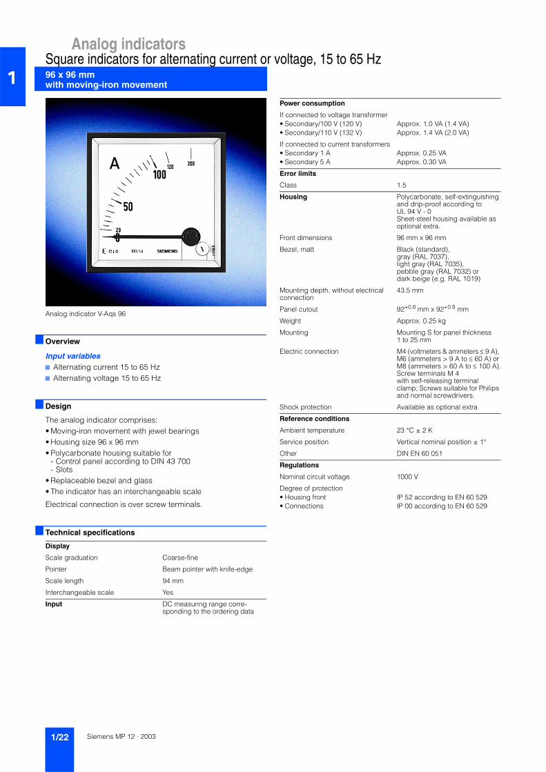
96 x 96 mm with moving-iron movement
Square indicators for alternating current or voltage, 15 to 65 Hz1
Analog indicator V-Aqs 96
Overview
Input variables7 Alternating current 15 to 65 Hz7 Alternating voltage 15 to 65 Hz
Design
The analog indicator comprises:• Moving-iron movement with jewel bearings• Housing size 96 x 96 mm• Polycarbonate housing suitable for
- Control panel according to DIN 43 700- Slots
• Replaceable bezel and glass• The indicator has an interchangeable scale
Electrical connection is over screw terminals.
Technical specifications
Display
Scale graduation Coarse-fine
Pointer Beam pointer with knife-edge
Scale length 94 mm
Interchangeable scale Yes
Input DC measuring range corre-sponding to the ordering data
Power consumption
If connected to voltage transformer• Secondary/100 V (120 V) Approx. 1.0 VA (1.4 VA)• Secondary/110 V (132 V) Approx. 1.4 VA (2.0 VA)
If connected to current transformers• Secondary 1 A Approx. 0.25 VA• Secondary 5 A Approx. 0.30 VA
Error limits
Class 1.5
Housing Polycarbonate, self-extinguishing and drip-proof according to UL 94 V - 0Sheet-steel housing available as optional extra.
Front dimensions 96 mm x 96 mm
Bezel, matt Black (standard),gray (RAL 7037),light gray (RAL 7035),pebble gray (RAL 7032) ordark beige (e.g. RAL 1019)
Mounting depth, without electrical connection
43.5 mm
Panel cutout 92+0.8 mm x 92+0.8 mm
Weight Approx. 0.25 kg
Mounting Mounting S for panel thickness 1 to 25 mm
Electric connection M4 (voltmeters & ammeters ≤ 9 A), M6 (ammeters > 9 A to ≤ 60 A) or M8 (ammeters > 60 A to ≤ 100 A).Screw terminals M 4 with self-releasing terminal clamp; Screws suitable for Philips and normal screwdrivers.
Shock protection Available as optional extra
Reference conditions
Ambient temperature 23 °C ± 2 K
Service position Vertical nominal position ± 1°
Other DIN EN 60 051
Regulations
Nominal circuit voltage 1000 V
Degree of protection• Housing front IP 52 according to EN 60 529• Connections IP 00 according to EN 60 529
Siemens MP 12 · 20031/22

Analog indicatorsSquare indicators for alternating current or voltage, 15 to 65 Hz
96 x 96 mmwith moving-iron movement 1
1) Specifications in plain text.2) Contains sheet-steel housing with cone-head rivets (Order No. M40)
and mounting B (Order No. B22).
3) Additional one-off engraving costs on request.
Selection and ordering data Order No. Order Code
Analog indicator 96 x 96 with moving-iron movementMeasurement input alternating current or alternating voltage
M0 1 6 0 4 -
E7777 777
Input variable• ... A/1 A, connection to current transformer 3 9 9 0 - Z Y 0 6 1)
• ... A/5 A, connection to current transformer 4 9 9 0 - Z Y 0 6 1)
• Input in the ranges: 9 9 9 9 - Z Y 0 6 1)
- 100 mA to 6 A- 6 V to 100 V- Voltage transformer secondary 100 V/110 V
primary ... V- Other inputs on request
Additional designsAvailable for all Order Nos. - max. 1 add-on per group. Supplement Order No. with -Z and order code
M0 1 6 0 4 -
E7777 777
Measuring instrument models
Measurement input• Alternating current/voltage (standard)• Direct current/voltage - Z M5 4• Direct/alternating current and direct/
alternating voltage- Z M5 3
Nominal frequency• 15 to 65 Hz (standard)• ... Hz
(one frequency in the range > 65 to 500 Hz) for voltmeters ≥ 40 V with standard ranges and ammeters ≤ 6 A
- Z N 1 3 1)
• ... Hz (one frequency in the range > 65 to 500 Hz) for ammeters > 6 A
- Z N 1 4 1)
Shielding• Installation conditions, normal (standard)• Increased external field protection - Z F 3 7
Accuracy• Class 1.5 (standard)• Class 1.0 (only for alternating current/
voltages 50 Hz)- Z K 0 2
Service position• Vertical (standard)• Horizontal - Z G 2 1• Other service position (specify angle of scale
surface from horizontal in plain text)- Z G 2 4 1)
Special requirements• Normal vibration and impact resistance
(standard)• Available for marine applications with the
following certifications (only Class 1.5; Measurement input ≥ 100 mA/≥ 6 V):- BV 0591 of Federal Navy - Z N 9 6 2)
- Germanischer Lloyd - Z N 9 7- Maritime Register of Shipping - Z N 0 9- Vibration resistance 2.5 g;
impact resistance 30 g- Z S 2 0
- Vibration resistance 5 g; impact resistance 50 g
- Z S 1 9
Selection and ordering data Order No. Order Code
Additional designsAvailable for all Order Nos. - max. 1 add-on per group. Supplement Order No. with -Z and order code
M0 1 6 0 4 -
E7777 777
Scale versions
Scale• Same as measurement input (standard)• Blank scale (start/end mark, logo, symbols) - Z B 8 5
Graduation and pointer• Single graduation, coarse-fine
(standard)• Double graduation - Z D 3 1• Fine graduation - Z F 3 1• Beam pointer with knife-edge
- for single graduation (standard)- for double graduation - Z Z 1 1
• Blade beam pointer- for single graduation - Z Z 0 2- for double graduation - Z Z 0 4
Additional imprint• Second numbering - Z S 0 5 1)
• Lettering- Without additional lettering (standard)- Lettering ≤ 15 characters German - Z S 0 2 1)
- Lettering > 15 characters German - Z S 1 0 1)
- Lettering ≤ 15 characters foreign language(using Latin lettering)
- Z S 1 2 1)
- Lettering > 15 characters foreign language(using Latin lettering)
- Z S 1 1 1)
Color marking• Colored mark, red RAL 2002 - Z F 2 1 1)
• Colored field, yellow RAL 1021, green RAL 6018 or red RAL 2002
- Z F 2 2 1)
Scale type • Flat interchangeable scale (standard)• Flat screw scale - Z S 5 7
Overload• No overload (standard)• 1.2-fold - Z U 0 1• 2-fold (only for ammeters) - Z U 0 2• 4-fold (only for ammeters;
full-scale reading ≤ 40 A)- Z U 0 3
Scale and pointer colors• Scale, white; printing and pointer black
(standard)• Scale, black; printing and pointer white - Z S 5 2 3)
• Scale, black; printing and pointer yellow - Z S 5 3 3)
• Without scale; Pointer, black (only for devices with connection to current and voltage transformers)
- Z S 6 2
• Without scale; Pointer, white(only for devices with connection to current and voltage transformers)
- Z S 6 3
• Without scale; Pointer, yellow(only for devices with connection to current and voltage transformers)
- Z S 6 4
Siemens MP 12 · 2003 1/23

Analog indicators
96 x 96 mm with moving-iron movement
Square indicators for alternating current or voltage, 15 to 65 Hz1
1) Specifications in plain text.
Dimension drawings
Analog indicator type V-Aqs 96, dimensions in mm
Selection and ordering data Order No. Order Code
Additional designsAvailable for all Order Nos. - max. 1 add-on per group. Supplement Order No. with -Z and order code
M0 1 6 0 4 -
E7777 777
Scale versions
Lighting• Without lighting (standard)• With lighting (direct)
(plexiscale, scale and lighting, white)(must be supplemented with Order No. B77, B78 or B79)
- Z B 5 0
Lamp voltage for lighting• 12 V - Z B 7 7• 24 V - Z B 7 8• 28 V - Z B 7 9
Housing models
Field of application• Standard• Conditionally tropic-proof - Z B 1 6
Degree of protection• Standard• Housing front panel IP 54, terminal IP 00 - Z S 2 2• Aseismic (only Class 1.5 - combination with
S22 possible)- Z E 3 6
Color of bezel• Black, matt (standard)• Gray, RAL 7037, matt - Z F 1 2• Pebble gray, RAL 7032, matt - Z F 1 8• Dark beige, like RAL 1019, matt - Z F 1 4• Light gray, RAL 7035, matt - Z F 0 5
Intermediate frame, 3 mm high• Without intermediate frame (standard)• Intermediate frame, black, gloss
(only in conjunction with mounting S or B)- Z Z 3 1
• Intermediate frame, gray RAL 7037, gloss(only in conjunction with mounting S or B)
- Z Z 3 2
Glass• Standard• Antiglare glass - Z G 0 1
Housing• Standard housing
(standard housing in conjunction with mounting B92 also suitable for Mauell and H&B Unibloc slots)
• Sheet-steel housing with cone-head rivets - Z M4 0
Mounting• Mounting S (panel thickness 1 to 25 mm)
(standard)• 2 leaf-springs (panel thickness 1 to 3 mm) - Z B 9 2• 4 leaf-springs (panel thickness 1 to 3 mm) - Z B 2 1• Mounting B (panel thickness 1 to 40 mm)
(only if ordered together with Order No. M40)- Z B 2 2
• Subklew fasteners(mounting S without pivot)
- Z B 1 5
• Without mounting - Z B 2 3
Selection and ordering data Order No. Order Code
Additional designsAvailable for all Order Nos. - max. 1 add-on per group. Supplement Order No. with -Z and order code
M0 1 6 0 4 -
E7777 777
Housing models
Device designation• Without designation (standard)• Designation on rear panel - Z K 1 1 1)
Constants indication• Without constant indication (standard)• Constant indication
1-1.5-2-2.5-3-4-5-6-7.5-8-10- Z K 3 5
Adjustable set pointer• Without adjustable set pointer (standard)• 1 adjustable set pointer, red - Z M0 1
Labeling strips• Without labeling strip (standard)• Labeling on the bottom of front panel - Z B 7 5 1)
Shock protection• Without protection against contact
(standard)• Overall protection against contact - Z B 0 8• Individual protection against contact
(voltmeters and ammeters ≤ 9 A)- Z B 1 3
Siemens MP 12 · 20031/24

Analog indicatorsSquare indicators for alternating current
96 x 96 mm with bimetal movementfor mean and maximum value 1
Analog indicator V-Mqs 96
Overview
Input variables7 Alternating current
Special features7 Mean value indication7 Maximum value indication
Design
The analog indicator comprises:• Bimetal movement with jewel bearings• Housing size 96 x 96 mm• Polycarbonate housing suitable for
- Control panel according to DIN 43 700- Slots
• Replaceable bezel and glass• The indicator has an interchangeable scale
Electrical connection is over screw terminals.
Technical specifications
Display
Scale graduation Coarse-fine
Pointer Beam pointer with knife-edge
Scale length 94 mm
Indication errors Max. ± 3 %
Interchangeable scale Yes
Input DC measuring range correspond-ing to the ordering data
Power consumption
If connected to current transformers• Secondary 1 A Approx. 1.1 VA• Secondary 5 A Approx. 1.9 VA
Housing Polycarbonate, self-extinguishing and drip-proof according to UL 94 V - 0Sheet-steel housing available as optional extra.
Front dimensions 96 mm x 96 mm
Bezel, matt Black (standard),gray (RAL 7037),light gray (RAL 7035),pebble gray (RAL 7032) ordark beige (e.g. RAL 1019)
Mounting depth, without electrical connection
43.5 mm
Panel cutout 92+0.8 mm x 92+0.8 mm
Weight Approx. 0.25 kg
Mounting Mounting S for panel thickness 1 to 25 mm
Electric connection Screw terminals M 4 with self-releasing terminal clamp; Screws suitable for Philips and normal screwdrivers.
Shock protection Available as optional extra
Reference conditions
Ambient temperature 23 °C ± 2 K
Service position Vertical nominal position ± 1°
Other DIN EN 60 051
Regulations
Nominal circuit voltage 1000 V
Degree of protection• Housing front IP 52 according to EN 60 529• Connections IP 00 according to EN 60 529
Siemens MP 12 · 2003 1/25

Analog indicators
96 x 96 mm with bimetal movementfor mean and maximum value
Square indicators for alternating current1
1) Specifications in plain text.2) Additional one-off engraving costs on request.
Dimension drawings
Analog indicator type V-Mqs 96, dimensions in mm
Selection and ordering data Order No. Order Code
Analog indicator 96 x 96 with bimetal move-ment for mean value and maximum valueMeasurement input alternating current
M0 1 6 0 4 -
M7777 777
Input variable• ... A, connection, direct (1 or 5 A) 9 9 9 9 - Z Y 0 6 1)
• ... A/1 A, connection to current transformer 3 9 9 0 - Z Y 0 6 1)
• ... A/5 A, connection to current transformer 4 9 9 0 - Z Y 0 6 1)
Additional designsAvailable for all Order Nos. - max. 1 add-on per group. Supplement Order No. with -Z and order code
M0 1 6 0 4 -
M7777 777
Measuring instrument models
Setting time• 15 min (standard)• 8 min - Z E 0 8
Overload• 1.2-fold (standard)• 1.5-fold (only for 0 to 5 A or secondary 5 A) - Z U 1 8• Overload 1.2-fold with integral protective cur-
rent transformer 50-fold/1s- Z U 2 0
• Overload 1.2-fold with separate protective current transformer 100-fold/1s
- Z U 2 1
Service position• Vertical (standard)• Horizontal - Z G 2 1• Other service position (specify angle of scale
surface from horizontal in plain text)- Z G 2 4 1)
Scale versions
Scale• Same as measurement input (standard)• Blank scale (start/end mark, logo, symbols) - Z B 8 5
Additional imprint• Second numbering - Z S 0 5 1)
• Lettering- Without additional lettering (standard)- Lettering ≤ 15 characters German - Z S 0 2 1)
- Lettering > 15 characters German - Z S 1 0 1)
- Lettering ≤ 15 characters foreign language(using Latin lettering)
- Z S 1 2 1)
- Lettering > 15 characters foreign language(using Latin lettering)
- Z S 1 1 1)
Color marking• Colored mark, red RAL 2002 - Z F 2 1 1)
• Colored field, yellow RAL 1021, green RAL 6018 or red RAL 2002
- Z F 2 2 1)
Scale and pointer colors• Scale, white; printing and pointer black
(standard)• Scale, black; printing and pointer white - Z S 5 2 2)
• Scale, black; printing and pointer yellow - Z S 5 3 2)
• Without scale; Pointer, black - Z S 6 2• Without scale; Pointer, white - Z S 6 3• Without scale; Pointer, yellow - Z S 6 4
Selection and ordering data Order No. Order Code
Additional designsAvailable for all Order Nos. - max. 1 add-on per group. Supplement Order No. with -Z and order code
M0 1 6 0 4 -
M7777 777
Housing models
Color of bezel• Black, matt (standard)• Gray, RAL 7037, matt - Z F 1 2• Pebble gray, RAL 7032, matt - Z F 1 8• Dark beige, like RAL 1019, matt - Z F 1 4• Light gray, RAL 7035, matt - Z F 0 5
Intermediate frame, 3 mm high• Without intermediate frame (standard)• Intermediate frame, black, gloss
(only in conjunction with mounting S or B)- Z Z 3 1
• Intermediate frame, gray RAL 7037, gloss(only in conjunction with mounting S or B)
- Z Z 3 2
Glass• Standard• Antiglare glass - Z G 0 1
Housing• Standard housing• Sheet-steel housing with cone-head rivets - Z M4 0
Mounting• Mounting S (panel thickness 1 to 25 mm)
(standard)• 2 leaf-springs (panel thickness 1 to 3 mm) - Z B 9 2• 4 leaf-springs (panel thickness 1 to 3 mm) - Z B 2 1• Mounting B (panel thickness 1 to 40 mm)
(only if ordered together with Order No. M40)- Z B 2 2
Device designation• Without designation (standard)• Designation on rear panel - Z K 1 1 1)
Constants indication• Without constant indication (standard)• Constant indication
1-1.5-2-2.5-3-4-5-6-7.5-8-10- Z K 3 5
Shock protection• Without protection against contact
(standard)• Overall protection against contact - Z B 0 8• Individual protection against contact - Z B 1 3
Siemens MP 12 · 20031/26

Analog indicatorsSquare indicators for alternating current72 x 72 mm with bimetal moving-iron movement
for mean, maximum and instantaneous value 1
Analog indicator V-MAqs 72
Overview
Input variables7 Alternating current
Special features7 Mean value indication7 Maximum value indication7 Instantaneous value indication
Design
The analog indicator comprises:• Bimetal moving-iron movement with jewel bearings• Housing size 72 x 72 mm• Polycarbonate housing suitable for
- Control panel according to DIN 43 700- Slots
• Replaceable bezel and glass• The indicator has an interchangeable scale
Electrical connection is over screw terminals.
Technical specifications
Display
Scale graduation Coarse-fine
Pointer Beam pointer with knife-edge
Scale length• Bimetal 66 mm• Moving-iron 60 mm
Indication error, bimetal Max. ± 3 %
Interchangeable scale Yes
Input DC measuring range correspond-ing to the ordering data
Power consumption
If connected to current transformers• Secondary 1 A
- Bimetal Approx. 1.1 VA- Moving-iron Approx. 0.25 VA
• Secondary 5 A- Bimetal Approx. 1.9 VA- Moving-iron Approx. 0.3 VA
Error limits
Class, moving-iron 1.5
Housing Polycarbonate, self-extinguishing and drip-proof according to UL 94 V - 0Sheet-steel housing available as optional extra.
Front dimensions 72 mm x 72 mm
Bezel, matt Black (standard),gray (RAL 7037),light gray (RAL 7035),pebble gray (RAL 7032) ordark beige (e.g. RAL 1019)
Mounting depth, without electrical connection
43.5 mm
Panel cutout 68+0.7 mm x 68+0.7 mm
Weight Approx. 0.3 kg
Mounting Mounting S for panel thickness 1 to 25 mm
Electric connection Screw terminals M 4 with self-releasing terminal clamp; Screws suitable for Philips and normal screwdrivers.
Shock protection Available as optional extra
Reference conditions
Ambient temperature 23 °C ± 2 K
Service position Vertical nominal position ± 1°
Other DIN EN 60 051
Regulations
Nominal circuit voltage 1000 V
Degree of protection• Housing front IP 50 according to EN 60 529• Connections IP 00 according to EN 60 529
Siemens MP 12 · 2003 1/27

Analog indicators
72 x 72 mm with bimetal moving-iron movementfor mean, maximum and instantaneous value
Square indicators for alternating current1
1) Specifications in plain text.2) Additional one-off engraving costs on request.
Dimension drawings
Analog indicator type V-MAqs 72, dimensions in mm
Selection and ordering data Order No. Order Code
Analog indicator 72 x 72 with bimetal mov-ing-iron movement for mean value, maxi-mum value and instantaneous valueMeasurement input alternating current, measuring system 1: Bimetal, measuring system 2: Moving-iron
M0 1 6 0 3 -
C7777 777
Input variable• ... A, connection, direct (1 or 5 A) 9 9 9 9 - Z Y 0 6 1)
• ... A/1 A, connection to current transformer 3 9 9 0 - Z Y 0 6 1)
• ... A/5 A, connection to current transformer 4 9 9 0 - Z Y 0 6 1)
Additional designsAvailable for all Order Nos. - max. 1 add-on per group. Supplement Order No. with -Z and order code
M0 1 6 0 3 -
C7777 777
Measuring instrument models
Setting time for bimetal movements• 15 min (standard)• 8 min - Z E 0 8
Overload for bimetal movements• 1.2-fold (standard)• 1.5-fold (only for 0 to 5 A or secondary 5 A) - Z U 1 8• Overload 1.2-fold with separate protective
current transformer 100-fold/1s- Z U 2 1
Overload for moving-iron movements• 1.2-fold (standard)• Double - Z U 2 2
Service position• Vertical (standard)• Horizontal - Z G 2 1• Other service position (specify angle of scale
surface from horizontal in plain text)- Z G 2 4 1)
Scale versions
Scale• Same as measurement input (standard)• Blank scale (start/end mark, logo, symbols) - Z B 8 5
Additional imprint• Lettering
- Without additional lettering (standard)- Lettering ≤ 15 characters German - Z S 0 2 1)
- Lettering > 15 characters German - Z S 1 0 1)
- Lettering ≤ 15 characters foreign language(using Latin lettering)
- Z S 1 2 1)
- Lettering > 15 characters foreign language(using Latin lettering)
- Z S 1 1 1)
Color marking• Colored mark, red RAL 2002 - Z F 2 1 1)
• Colored field, yellow RAL 1021, green RAL 6018 or red RAL 2002
- Z F 2 2 1)
Scale and pointer colors• Scale, white; printing and pointer black
(standard)• Scale, black; printing and pointer white - Z S 5 2 2)
• Scale, black; printing and pointer yellow - Z S 5 3 2)
• Without scale; Pointer, black - Z S 6 2• Without scale; Pointer, white - Z S 6 3• Without scale; Pointer, yellow - Z S 6 4
Selection and ordering data Order No. Order Code
Additional designsAvailable for all Order Nos. - max. 1 add-on per group. Supplement Order No. with -Z and order code
M0 1 6 0 3 -
C7777 777
Housing models
Color of bezel• Black, matt (standard)• Gray, RAL 7037, matt - Z F 1 2• Pebble gray, RAL 7032, matt - Z F 1 8• Dark beige, like RAL 1019, matt - Z F 1 4• Light gray, RAL 7035, matt - Z F 0 5
Intermediate frame, 3 mm high• Without intermediate frame (standard)• Intermediate frame, black, gloss
(only in conjunction with mounting S or B)- Z Z 3 1
• Intermediate frame, gray RAL 7037, gloss(only in conjunction with mounting S or B)
- Z Z 3 2
Glass• Standard• Antiglare glass - Z G 0 1
Housing• Standard housing• Sheet-steel housing with cone-head rivets - Z M4 0
Mounting• Mounting S (panel thickness 1 to 25 mm)
(standard)• 2 leaf-springs (panel thickness 1 to 3 mm) - Z B 9 2• 4 leaf-springs (panel thickness 1 to 3 mm) - Z B 2 1• Mounting B (panel thickness 1 to 40 mm)
(only if ordered together with Order No. M40)- Z B 2 2
Device designation• Without designation (standard)• Designation on rear panel - Z K 1 1 1)
Shock protection• Without protection against contact
(standard)• Overall protection against contact - Z B 0 8• Individual protection against contact - Z B 1 3
Siemens MP 12 · 20031/28

Analog indicatorsSquare indicators for alternating current96 x 96 mm with bimetal moving-iron movement
for mean, maximum and instantaneous value 1
Analog indicator V-MAqs 96
Overview
Input variables7 Alternating current
Special features7 Mean value indication7 Maximum value indication7 Instantaneous value indication
Design
The analog indicator comprises:• Bimetal moving-iron movement with jewel bearings• Housing size 96 x 96 mm• Polycarbonate housing suitable for
- Control panel according to DIN 43 700- Slots
• Replaceable bezel and glass• The indicator has an interchangeable scale
Electrical connection is over screw terminals.
Technical specifications
Display
Scale graduation Coarse-fine
Pointer Beam pointer with knife-edge
Scale length• Bimetal 94 mm• Moving-iron 81 mm
Indication error, bimetal Max. ± 3 %
Interchangeable scale Yes
Input DC measuring range correspond-ing to the ordering data
Power consumption
If connected to current transformers• Secondary 1 A
- Bimetal Approx. 1.1 VA- Moving-iron Approx. 0.25 VA
• Secondary 5 A- Bimetal Approx. 1.9 VA- Moving-iron Approx. 0.3 VA
Error limits
Class, moving-iron 1.5
Housing Polycarbonate, self-extinguishing and drip-proof according to UL 94 V - 0Sheet-steel housing available as optional extra.
Front dimensions 96 mm x 96 mm
Bezel, matt Black (standard),gray (RAL 7037),light gray (RAL 7035),pebble gray (RAL 7032) ordark beige (e.g. RAL 1019)
Mounting depth, without electrical connection
43.5 mm
Panel cutout 92+0.8 mm x 92+0.8 mm
Weight Approx. 0.35 kg
Mounting Mounting S for panel thickness 1 to 25 mm
Electric connection Screw terminals M 4 with self-releasing terminal clamp; Screws suitable for Philips and normal screwdrivers.
Shock protection Available as optional extra
Reference conditions
Ambient temperature 23 °C ± 2 K
Service position Vertical nominal position ± 1°
Other DIN EN 60 051
Regulations
Nominal circuit voltage 1000 V
Degree of protection• Housing front IP 50 according to EN 60 529• Connections IP 00 according to EN 60 529
Siemens MP 12 · 2003 1/29
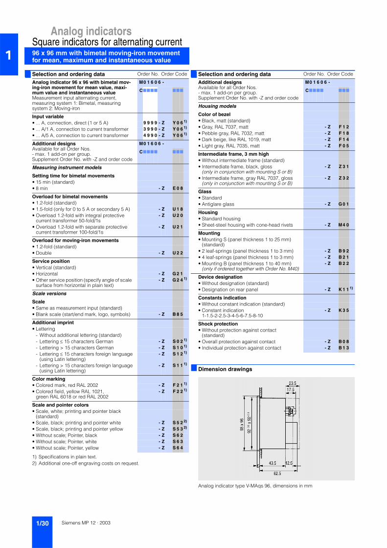
Analog indicators
96 x 96 mm with bimetal moving-iron movement for mean, maximum and instantaneous value
Square indicators for alternating current1
1) Specifications in plain text.2) Additional one-off engraving costs on request.
Dimension drawings
Analog indicator type V-MAqs 96, dimensions in mm
Selection and ordering data Order No. Order Code
Analog indicator 96 x 96 with bimetal mov-ing-iron movement for mean value, maxi-mum value and instantaneous valueMeasurement input alternating current, measuring system 1: Bimetal, measuring system 2: Moving-iron
M0 1 6 0 6 -
C7777 777
Input variable• ... A, connection, direct (1 or 5 A) 9 9 9 9 - Z Y 0 6 1)
• ... A/1 A, connection to current transformer 3 9 9 0 - Z Y 0 6 1)
• ... A/5 A, connection to current transformer 4 9 9 0 - Z Y 0 6 1)
Additional designsAvailable for all Order Nos. - max. 1 add-on per group. Supplement Order No. with -Z and order code
M0 1 6 0 6 -
C7777 777
Measuring instrument models
Setting time for bimetal movements• 15 min (standard)• 8 min - Z E 0 8
Overload for bimetal movements• 1.2-fold (standard)• 1.5-fold (only for 0 to 5 A or secondary 5 A) - Z U 1 8• Overload 1.2-fold with integral protective
current transformer 50-fold/1s- Z U 2 0
• Overload 1.2-fold with separate protective current transformer 100-fold/1s
- Z U 2 1
Overload for moving-iron movements• 1.2-fold (standard)• Double - Z U 2 2
Service position• Vertical (standard)• Horizontal - Z G 2 1• Other service position (specify angle of scale
surface from horizontal in plain text)- Z G 2 4 1)
Scale versions
Scale• Same as measurement input (standard)• Blank scale (start/end mark, logo, symbols) - Z B 8 5
Additional imprint• Lettering
- Without additional lettering (standard)- Lettering ≤ 15 characters German - Z S 0 2 1)
- Lettering > 15 characters German - Z S 1 0 1)
- Lettering ≤ 15 characters foreign language(using Latin lettering)
- Z S 1 2 1)
- Lettering > 15 characters foreign language(using Latin lettering)
- Z S 1 1 1)
Color marking• Colored mark, red RAL 2002 - Z F 2 1 1)
• Colored field, yellow RAL 1021, green RAL 6018 or red RAL 2002
- Z F 2 2 1)
Scale and pointer colors• Scale, white; printing and pointer black
(standard)• Scale, black; printing and pointer white - Z S 5 2 2)
• Scale, black; printing and pointer yellow - Z S 5 3 2)
• Without scale; Pointer, black - Z S 6 2• Without scale; Pointer, white - Z S 6 3• Without scale; Pointer, yellow - Z S 6 4
Selection and ordering data Order No. Order Code
Additional designsAvailable for all Order Nos. - max. 1 add-on per group. Supplement Order No. with -Z and order code
M0 1 6 0 6 -
C7777 777
Housing models
Color of bezel• Black, matt (standard)• Gray, RAL 7037, matt - Z F 1 2• Pebble gray, RAL 7032, matt - Z F 1 8• Dark beige, like RAL 1019, matt - Z F 1 4• Light gray, RAL 7035, matt - Z F 0 5
Intermediate frame, 3 mm high• Without intermediate frame (standard)• Intermediate frame, black, gloss
(only in conjunction with mounting S or B)- Z Z 3 1
• Intermediate frame, gray RAL 7037, gloss(only in conjunction with mounting S or B)
- Z Z 3 2
Glass• Standard• Antiglare glass - Z G 0 1
Housing• Standard housing• Sheet-steel housing with cone-head rivets - Z M4 0
Mounting• Mounting S (panel thickness 1 to 25 mm)
(standard)• 2 leaf-springs (panel thickness 1 to 3 mm) - Z B 9 2• 4 leaf-springs (panel thickness 1 to 3 mm) - Z B 2 1• Mounting B (panel thickness 1 to 40 mm)
(only if ordered together with Order No. M40)- Z B 2 2
Device designation• Without designation (standard)• Designation on rear panel - Z K 1 1 1)
Constants indication• Without constant indication (standard)• Constant indication
1-1.5-2-2.5-3-4-5-6-7.5-8-10- Z K 3 5
Shock protection• Without protection against contact
(standard)• Overall protection against contact - Z B 0 8• Individual protection against contact - Z B 1 3
Siemens MP 12 · 20031/30
![A Scalable Heterogeneous Solution for Massive Data ... [Read-Only].pdf · §Data warehouse of key performance indicators ... Global Business Services DB Siemens Ericsson ... Global](https://img.pdfslide.us/doc/110x75/5a71120d7f8b9a93538c9d13/a-scalable-heterogeneous-solution-for-massive-data-read-onlypdfpdf.jpg)