Embed Size (px)
Citation preview
Analog Computation by DNA Strand Displacement CircuitsTianqi Song, Sudhanshu Garg, Reem Mokhtar, Hieu Bui, and John Reif*
Department of Computer Science, Duke University, Durham, North Carolina 27708, United States
*S Supporting Information
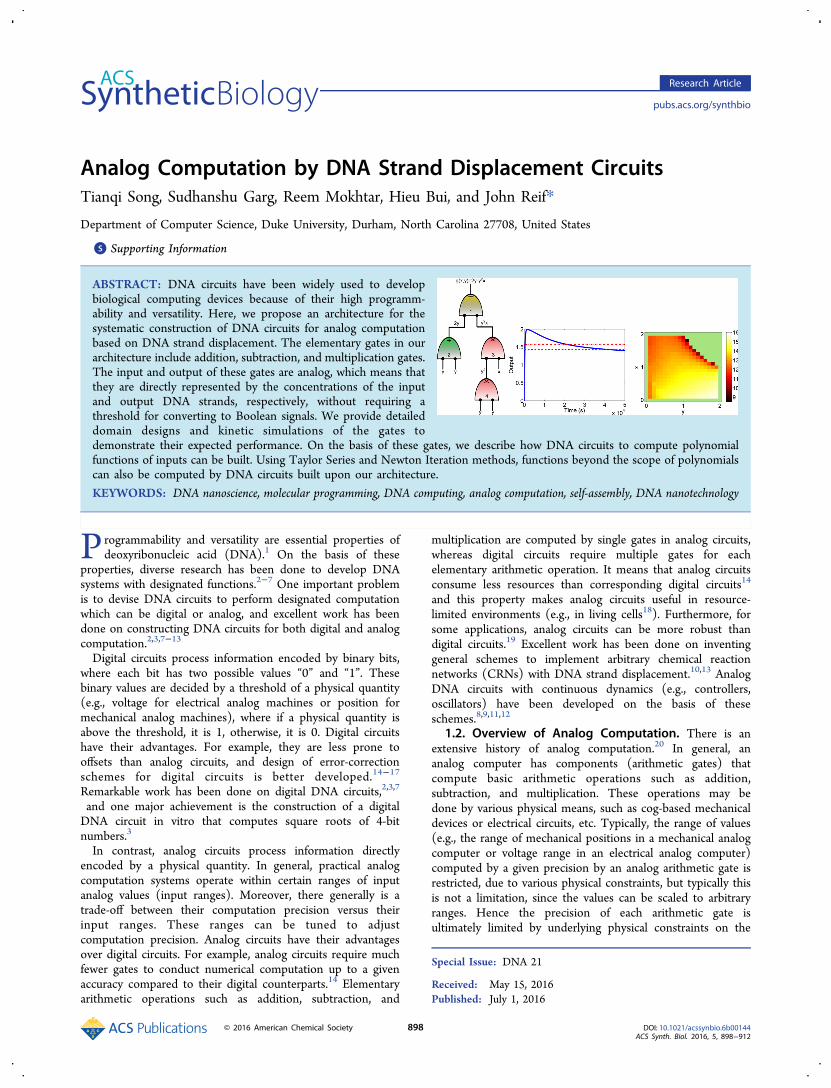
ABSTRACT: DNA circuits have been widely used to developbiological computing devices because of their high programm-ability and versatility. Here, we propose an architecture for thesystematic construction of DNA circuits for analog computationbased on DNA strand displacement. The elementary gates in ourarchitecture include addition, subtraction, and multiplication gates.The input and output of these gates are analog, which means thatthey are directly represented by the concentrations of the inputand output DNA strands, respectively, without requiring athreshold for converting to Boolean signals. We provide detaileddomain designs and kinetic simulations of the gates todemonstrate their expected performance. On the basis of these gates, we describe how DNA circuits to compute polynomialfunctions of inputs can be built. Using Taylor Series and Newton Iteration methods, functions beyond the scope of polynomialscan also be computed by DNA circuits built upon our architecture.
KEYWORDS: DNA nanoscience, molecular programming, DNA computing, analog computation, self-assembly, DNA nanotechnology
Programmability and versatility are essential properties ofdeoxyribonucleic acid (DNA).1 On the basis of these
properties, diverse research has been done to develop DNAsystems with designated functions.2−7 One important problemis to devise DNA circuits to perform designated computationwhich can be digital or analog, and excellent work has beendone on constructing DNA circuits for both digital and analogcomputation.2,3,7−13
Digital circuits process information encoded by binary bits,where each bit has two possible values “0” and “1”. Thesebinary values are decided by a threshold of a physical quantity(e.g., voltage for electrical analog machines or position formechanical analog machines), where if a physical quantity isabove the threshold, it is 1, otherwise, it is 0. Digital circuitshave their advantages. For example, they are less prone tooffsets than analog circuits, and design of error-correctionschemes for digital circuits is better developed.14−17
Remarkable work has been done on digital DNA circuits,2,3,7
and one major achievement is the construction of a digitalDNA circuit in vitro that computes square roots of 4-bitnumbers.3
In contrast, analog circuits process information directlyencoded by a physical quantity. In general, practical analogcomputation systems operate within certain ranges of inputanalog values (input ranges). Moreover, there generally is atrade-off between their computation precision versus theirinput ranges. These ranges can be tuned to adjustcomputation precision. Analog circuits have their advantagesover digital circuits. For example, analog circuits require muchfewer gates to conduct numerical computation up to a givenaccuracy compared to their digital counterparts.14 Elementaryarithmetic operations such as addition, subtraction, and
multiplication are computed by single gates in analog circuits,whereas digital circuits require multiple gates for eachelementary arithmetic operation. It means that analog circuitsconsume less resources than corresponding digital circuits14
and this property makes analog circuits useful in resource-limited environments (e.g., in living cells18). Furthermore, forsome applications, analog circuits can be more robust thandigital circuits.19 Excellent work has been done on inventinggeneral schemes to implement arbitrary chemical reactionnetworks (CRNs) with DNA strand displacement.10,13 AnalogDNA circuits with continuous dynamics (e.g., controllers,oscillators) have been developed on the basis of theseschemes.8,9,11,12
1.2. Overview of Analog Computation. There is anextensive history of analog computation.20 In general, ananalog computer has components (arithmetic gates) thatcompute basic arithmetic operations such as addition,subtraction, and multiplication. These operations may bedone by various physical means, such as cog-based mechanicaldevices or electrical circuits, etc. Typically, the range of values(e.g., the range of mechanical positions in a mechanical analogcomputer or voltage range in an electrical analog computer)computed by a given precision by an analog arithmetic gate isrestricted, due to various physical constraints, but typically thisis not a limitation, since the values can be scaled to arbitraryranges. Hence the precision of each arithmetic gate isultimately limited by underlying physical constraints on the
Special Issue: DNA 21
Received: May 15, 2016Published: July 1, 2016
Research Article
pubs.acs.org/synthbio
© 2016 American Chemical Society 898 DOI: 10.1021/acssynbio.6b00144ACS Synth. Biol. 2016, 5, 898−912
devices that implement the arithmetic gate, but the precisioncan typically be tuned by adjusting the input ranges. Allknown analog computers (including in particular ourproposed DNA-based analog circuits) appear to have somesort of trade-off between precision of analog values computedand the operating range of values over which the analogcomputations are done. Analog devices can offer someadvantages (such as requiring a smaller number of gates)over computing devices whose gates can only execute Booleanoperations. The same issues of advantages (e.g., in number ofgates) and limitations (e.g., in the range of values, butreleased via rescaling) appear in the DNA-based analogcircuits of this paper. Analog circuits for arithmetic operationscompute the outputs whose values are determined by theinputs. Analog circuits with continuous dynamics generateoutputs that are designated functions in the time domain.1.3. Potential Applications of Analog DNA Circuits.
Analog DNA circuits can be used as analog controldevices11,12 in which real values are sensed and analogcomputation provides controlling output. For example, controlof chemical reaction networks requires both sensing ofconcentrations of input molecules and after analog computa-tion, controlling concentrations of output molecules. Also, inapplications known as “DNA doctor”,21 in which variousnucleic acid sequence concentrations (e.g., concentrations ofmRNAs) are sensed, and an analog computation can be usedto determine the amount of a drug molecule that should bereleased. Prior devices for control of chemical reactionnetworks and DNA doctor21 applications have been limitedto finite-state control, and analog DNA circuits will allowmuch more sophisticated analog signal processing and control.DNA robotics have allowed devices to operate autonomously(e.g., to walk on a nanostructure) but also have been limitedto finite-state control. Analog DNA circuits can allowmolecular robots to include real-time analog control circuitsto provide much more sophisticated control than offered bypurely digital control. Many artificial intelligence systems (e.g.,neural networks and probabilistic inference) that dynamicallylearn from environments require analog computation,14 andanalog DNA circuits can be used for back-propagationcomputation of neural networks and Bayesian probabilisticinference systems.1.4. Prior Molecular-Scale Analog Computation.
There is considerable excellent prior work on engineeringnucleic acid systems8−12,22−24 (both using enzymes andenzyme-free) and cells18,25,26 to do complex dynamics. Forexample, the following ingenious prior systems have beendemonstrated to compute time-varying cyclic signals: (a) anucleic acid system using enzymes,22 (b) a DNA-based systemusing only hybridization reactions,8 (c) and a cell-basedsystem.25 Prior work on analog DNA systems has mainlyfocused on developing DNA circuits with continuousdynamics.8,9,11,12 There is still a need to develop anarchitecture to construct analog DNA circuits for arithmeticcomputation. In principle, the general schemes to implementarbitrary chemical reaction networks (CRNs) with DNAstrand displacement10,13 can serve as such an architecture, butthere needs to be more detailed investigation.1.5. Our Contribution. In this paper, we present an
architecture to construct DNA circuits for arithmeticcomputation in an analog fashion. There are three elementarygates in our architecture: addition, subtraction, and multi-plication gates. For each gate, we first propose its high-level
chemical reaction network analogy and then give our DNAimplementation. Each gate is evaluated by simulation usingLanguage for Biochemical Systems (LBS).27 DNA circuits tocompute polynomial functions of inputs can be built on thebasis of these gates. By Taylor Series and Newton Iterationmethods, some functions beyond the scope of polynomialscan also be computed by DNA circuits built upon ourarchitecture.
2. RESULTS2.1. Preliminaries of Analog DNA Gates. 2.1.1. Toe-
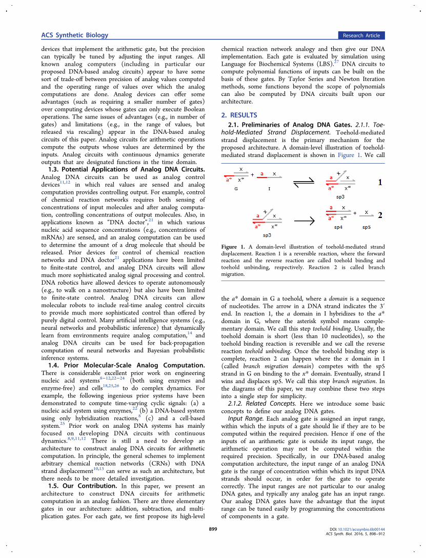
hold-Mediated Strand Displacement. Toehold-mediatedstrand displacement is the primary mechanism for theproposed architecture. A domain-level illustration of toehold-mediated strand displacement is shown in Figure 1. We call
the a* domain in G a toehold, where a domain is a sequenceof nucleotides. The arrow in a DNA strand indicates the 3′end. In reaction 1, the a domain in I hybridizes to the a*domain in G, where the asterisk symbol means comple-mentary domain. We call this step toehold binding. Usually, thetoehold domain is short (less than 10 nucleotides), so thetoehold binding reaction is reversible and we call the reversereaction toehold unbinding. Once the toehold binding step iscomplete, reaction 2 can happen where the x domain in I(called branch migration domain) competes with the sp5strand in G on binding to the x* domain. Eventually, strand Iwins and displaces sp5. We call this step branch migration. Inthe diagrams of this paper, we may combine these two stepsinto a single step for simplicity.
2.1.2. Related Concepts. Here we introduce some basicconcepts to define our analog DNA gates.
Input Range. Each analog gate is assigned an input range,within which the inputs of a gate should lie if they are to becomputed within the required precision. Hence if one of theinputs of an arithmetic gate is outside its input range, thearithmetic operation may not be computed within therequired precision. Specifically, in our DNA-based analogcomputation architecture, the input range of an analog DNAgate is the range of concentration within which its input DNAstrands should occur, in order for the gate to operatecorrectly. The input ranges are not particular to our analogDNA gates, and typically any analog gate has an input range.Our analog DNA gates have the advantage that the inputrange can be tuned easily by programming the concentrationsof components in a gate.
Figure 1. A domain-level illustration of toehold-mediated stranddisplacement. Reaction 1 is a reversible reaction, where the forwardreaction and the reverse reaction are called toehold binding andtoehold unbinding, respectively. Reaction 2 is called branchmigration.
ACS Synthetic Biology Research Article
DOI: 10.1021/acssynbio.6b00144ACS Synth. Biol. 2016, 5, 898−912
899
Valid Output Range. Analog gates process continuousphysical quantities as input and provide continuous output.This makes analog gates suffer more from two thingscompared to digital gates: signal fluctuation and signaldegradation. Continuous information is more sensitive tonoise and more difficult to restore than discrete informationencoded by binary bits. Therefore, due to noise, the output ofan analog gate cannot remain at the theoretically correct valuefor given inputs. There will always be an error, which usuallytends to grow larger over time due to signal degradation. Toevaluate analog gates, we define the term valid output range:Given inputs x1 and x2, a gate that conducts arithmeticoperation ⊗, and 0 < r < 1 which describes the error, thevalid output range is ((1 − r)*(x1⊗ x2), (1 + r)*(x1⊗ x2))for inputs x1 and x2. The output lying within this range isconsidered correct. The time that the output stays within thevalid output range is used to quantify the performance of thegate under these inputs. The value of r does not reallyinfluence the execution of a gate and it is just a parameter forinterpreting the performance.Note that all known analog systems, like electronic and
mechanical analog systems, have restricted input ranges.Fluctuation and degradation of output signal is also acommon problem for all known analog systems, whichnecessitates a valid output range. These properties areunavoidable for all analog systems,14 not only for our DNA-based analog system.2.2. Abstractions of the Gates. The abstractions in
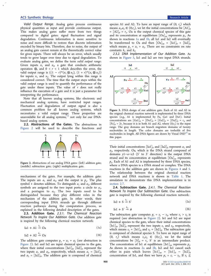
Figure 2 will be used to describe the functions and
mechanisms of the gates. For example, the addition gate:The inputs are a1 and a2, and the output is pa. The plussymbol + denotes addition. To distinguish a1 and a2, differentsymbols are assigned to the two input ports: a circle to a1,and a pentagon to a2. The two inputs need to bedistinguished because they play different roles in themechanism of the addition gate. In other words, theircorresponding input DNA strands go through differentreaction pathways during the computation process, asexplained in the following detailed description of the gates.2.3. Addition Gate. 2.3.1. The Chemical Reaction
Network To Inspire Our Addition Gate. Our addition gateis inspired by the following chemical reaction network:
+ →Ia1 A1 Oak1 (1a)
+ →Ia2 A2 Oak2 (1b)
The addition gate computes pa = a1 + a2 (see abstraction inFigure 2). Ia1 and Ia2 are input chemical species to the gate,where their initial concentrations [Ia1]0, [Ia2]0 represent thetwo inputs a1 and a2, respectively, which means a1 = [Ia1]0and a2 = [Ia2]0. The addition gate is composed of chemical
species A1 and A2. To have an input range of (0, ra) whichmeans a1,a2 ∈ (0,ra), we let the initial concentrations be [A1]0= [A2]0 = ra. Oa is the output chemical species of this gateand its concentration at equilibrium [Oa]∞ represents pa. Asshown in reactions 1a and 1b, all Ia1 and Ia2 will eventuallybe transformed to Oa and then [Oa]∞ = [Ia1]0 + [Ia2]0which means pa = a1 + a2. There are no constraints on rateconstants k1 and k2.
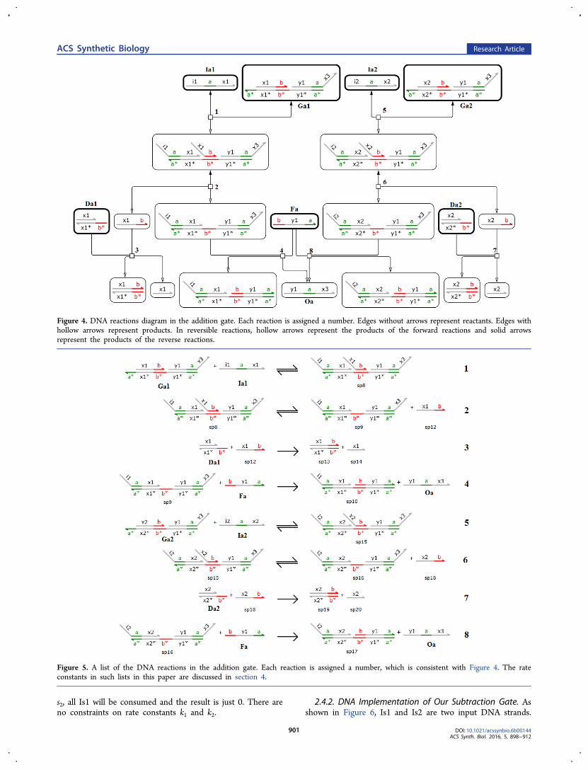
2.3.2. DNA Implementation of Our Addition Gate. Asshown in Figure 3, Ia1 and Ia2 are two input DNA strands.
Their initial concentrations [Ia1]0 and [Ia2]0 represent a1 anda2, respectively. Oa, which is the DNA strand composed ofdomains y1−a−x3 (5′ to 3′ direction) is the output DNAstrand and its concentration at equilibrium [Oa]∞ representspa. Each of A1 and A2 is implemented by three DNA species,where a DNA species is a DNA strand or complex. The DNAreactions in the addition gate are shown in Figures 4 and 5.The relationship between the original chemical reactionnetwork and DNA reactions is shown in Table 1. Thesimulation to demonstrate this DNA implementation is insection 2.7.
2.4. Subtraction Gate. 2.4.1. The Chemical ReactionNetwork To Inspire Our Subtraction Gate. Our subtractiongate is inspired by the following chemical reaction network:
+ → ′Is2 S Sk1 (2a)
+ ′ → ⌀Is1 Sk2 (2b)
The subtraction gate computes ps = s1 − s2, where s1 > s2 isrequired (see abstraction in Figure 2). Is1 and Is2 are inputchemical species to the gate, where their initial concentrations[Is1]0, [Is2]0 represent the two inputs s1 and s2, respectively,which means s1 = [Is1]0 and s2 = [Is2]0. The subtraction gateis composed of chemical species S. To have an input range of(0, rs) which means s1,s2 ∈ (0,rs), we let the initialconcentrations be [S]0 = rs. S′ is an intermediate product.The concentration of Is1 at equilibrium [Is1]∞ represents ps.As shown in reactions 2a and 2b, Is2 and Is1 cancel eachother in pairs which leaves [Is1]∞ = [Is1]0 − [Is2]0concentration of Is1, and then we have ps = s1 − s2. If s1 ≤
Figure 2. Abstractions of our analog DNA gates: (left) addition gate;(middle) subtraction gate; (right) multiplication gate.
Figure 3. DNA design of our addition gate. Each of A1 and A2 inthe original chemical reaction network is implemented by three DNAspecies (e.g., A1 is implemented by Fa, Ga1 and Da1). Initialconcentrations are [Ga1]0 = [Da1]0 = [Ga2]0 = [Da2]0 = ra, and[Fa]0 = 2ra because it is in both A1 and A2, where (0,ra) is the inputrange. The gray domains are branch migration domains of twentynucleotides in length. The color domains are toeholds of fivenucleotides in length. All DNA figures are drawn by Visual DSD28 inthis paper.
ACS Synthetic Biology Research Article
DOI: 10.1021/acssynbio.6b00144ACS Synth. Biol. 2016, 5, 898−912
900
s2, all Is1 will be consumed and the result is just 0. There areno constraints on rate constants k1 and k2.
2.4.2. DNA Implementation of Our Subtraction Gate. Asshown in Figure 6, Is1 and Is2 are two input DNA strands.
Figure 4. DNA reactions diagram in the addition gate. Each reaction is assigned a number. Edges without arrows represent reactants. Edges withhollow arrows represent products. In reversible reactions, hollow arrows represent the products of the forward reactions and solid arrowsrepresent the products of the reverse reactions.
Figure 5. A list of the DNA reactions in the addition gate. Each reaction is assigned a number, which is consistent with Figure 4. The rateconstants in such lists in this paper are discussed in section 4.
ACS Synthetic Biology Research Article
DOI: 10.1021/acssynbio.6b00144ACS Synth. Biol. 2016, 5, 898−912
901
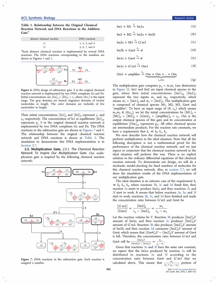
Their initial concentrations [Is1]0 and [Is2]0 represent s1 ands2, respectively. The concentration of Is1 at equilibrium [Is1]∞represents ps. S in the original chemical reaction network isimplemented by two DNA complexes Gs and Ds. The DNAreactions in the subtraction gate are shown in Figures 7 and 8.The relationship between the original chemical reactionnetwork and DNA reactions is shown in Table 2. Thesimulation to demonstrate this DNA implementation is inSection 2.7.2.5. Multiplication Gate. 2.5.1. The Chemical Reaction
Network To Inspire Our Multiplication Gate. Our multi-plication gate is inspired by the following chemical reactionnetwork:
+ →Im1 M1 Im1aks (3a)
+ → +Im2 M2 Im2a Im2bkf (3b)
+ → ′Im2a M3 G m3k1 (3c)
+ → ⌀Im2b Gm4k2 (3d)
+ → ⌀Im1a Gm4k3 (3e)
+ ′ →Im1a G m3 Om1k3 (3f)
+ → + + + Om1 amplifier Om Om .. Omk
r Om
4
m (3g)
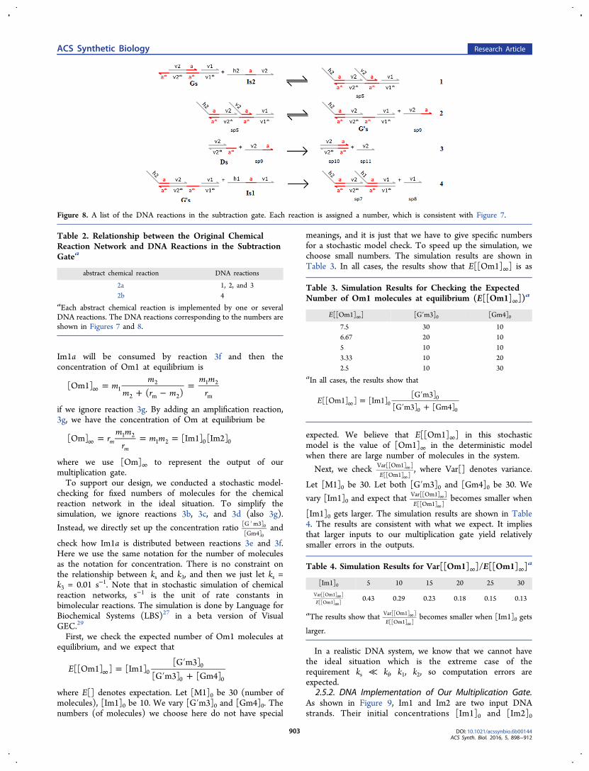
The multiplication gate computes pm = m1m2 (see abstractionin Figure 2). Im1 and Im2 are input chemical species to thegate, where their initial concentrations [Im1]0, [Im2]0represent the two inputs m1 and m2, respectively, whichmeans m1 = [Im1]0 and m2 = [Im2]0. The multiplication gateis composed of chemical species M1, M2, M3, Gm4 and“amplifier”. To have an input range of (0, rm) which meansm1,m2 ∈ (0,rm), we let the initial concentrations be [M1]0 =[M2]0 = [M3]0 = [Gm4]0 = [amplifier]0 = rm. Om is theoutput chemical species of this gate and its concentration atequilibrium [Om]∞ represents pm. All other chemical speciesare intermediate products. For the reaction rate constants, wehave a requirement that ks ≪ kf, k1, k2.We now describe how the chemical reaction network will
perform multiplication in the ideal situation. Note that all thefollowing description is not a mathematical proof for theperformance of the chemical reaction network, and we justexpect or conjecture that the chemical reaction network in theideal situation will perform this way. There is no explicitsolution to the ordinary differential equations of this chemicalreaction network. To demonstrate our design, we will do astochastic model-checking for fixed numbers of molecules forthis chemical reaction network. Also, in section 2.7, we willshow the simulation results of the DNA implementation ofour multiplication gate.The ideal situation is an extreme case of the requirement ks
≪ kf, k1, k2, where reactions 3b, 3c and 3d finish first, thenreaction 3a starts to produce Im1a, and then reactions 3e and3f start to work. It means that before reactions 3a, 3e, and 3fstart to work, reactions 3b, 3c, and 3d have finished and madethe concentration ratio between G′m3 and Gm4 be
′ =−
=−rm
r m[G m3][Gm4]
[Im2][Im2]
0
m 0
2
m 2
Let the reaction volume be V. Reaction 3b produces [Im2]0Vamount of Im2a, and then reaction 3c produces [Im2]0Vamount of G′m3. Reaction 3b also produces [Im2]0V amountof Im2b, and then reaction 3d consumes [Im2]0V amount ofGm4, which means that [Gm4]0V − [Im2]0V amount of Gm4is left. Therefore, the concentration ratio between G′m3 and
Gm4 will be =− −
VV V
mr m
[Im2][Gm4] [Im2]
0
0 0
2
m 2.
Given that reactions 3e and 3f have the same rate constant,we expect that the Im1a produced by reaction 3a will bedistributed to reactions 3e and 3f according to theconcentration ratio between Gm4 and G′m3 that wecalculated above. This means that
+ −m
m r m( )2
2 m 2portion of
Table 1. Relationship between the Original ChemicalReaction Network and DNA Reactions in the AdditionGatea
abstract chemical reaction DNA reactions
1a 1, 2, 3, and 41b 5, 6, 7, and 8
aEach abstract chemical reaction is implemented by several DNAreactions. The DNA reactions corresponding to the numbers areshown in Figures 4 and 5.
Figure 6. DNA design of subtraction gate. S in the original chemicalreaction network is implemented by two DNA complexes Gs and Ds.Initial concentrations are [Gs]0 = [Ds]0 = rs, where (0,rs) is the inputrange. The gray domains are branch migration domains of twentynucleotides in length. The color domains are toeholds of fivenucleotides in length.
Figure 7. DNA reactions in the subtraction gate. Each reaction isassigned a number.
ACS Synthetic Biology Research Article
DOI: 10.1021/acssynbio.6b00144ACS Synth. Biol. 2016, 5, 898−912
902
Im1a will be consumed by reaction 3f and then theconcentration of Om1 at equilibrium is
=+ −
=∞ mm
m r mm m
r[Om1]
( )12
2 m 2
1 2
m
if we ignore reaction 3g. By adding an amplification reaction,3g, we have the concentration of Om at equilibrium be
= = =∞ rm m
rm m[Om] [Im1] [Im2]m
m
1 21 2 0 0
where we use [Om]∞ to represent the output of ourmultiplication gate.To support our design, we conducted a stochastic model-
checking for fixed numbers of molecules for the chemicalreaction network in the ideal situation. To simplify thesimulation, we ignore reactions 3b, 3c, and 3d (also 3g).
Instead, we directly set up the concentration ratio ′[G m3][Gm4]
0
0and
check how Im1a is distributed between reactions 3e and 3f.Here we use the same notation for the number of moleculesas the notation for concentration. There is no constraint onthe relationship between ks and k3, and then we just let ks =k3 = 0.01 s−1. Note that in stochastic simulation of chemicalreaction networks, s−1 is the unit of rate constants inbimolecular reactions. The simulation is done by Language forBiochemical Systems (LBS)27 in a beta version of VisualGEC.29
First, we check the expected number of Om1 molecules atequilibrium, and we expect that
=′
′ +∞E[[Om1] ] [Im1][G m3]
[G m3] [Gm4]00
0 0
where E[] denotes expectation. Let [M1]0 be 30 (number ofmolecules), [Im1]0 be 10. We vary [G′m3]0 and [Gm4]0. Thenumbers (of molecules) we choose here do not have special
meanings, and it is just that we have to give specific numbersfor a stochastic model check. To speed up the simulation, wechoose small numbers. The simulation results are shown inTable 3. In all cases, the results show that E[[Om1]∞] is as
expected. We believe that E[[Om1]∞] in this stochasticmodel is the value of [Om1]∞ in the deterministic modelwhen there are large number of molecules in the system.
Next, we check ∞
∞EVar[[Om1] ]
[[Om1] ], where Var[] denotes variance.
Let [M1]0 be 30. Let both [G′m3]0 and [Gm4]0 be 30. We
vary [Im1]0 and expect that ∞
∞EVar[[Om1] ]
[[Om1] ]becomes smaller when
[Im1]0 gets larger. The simulation results are shown in Table4. The results are consistent with what we expect. It impliesthat larger inputs to our multiplication gate yield relativelysmaller errors in the outputs.
In a realistic DNA system, we know that we cannot havethe ideal situation which is the extreme case of therequirement ks ≪ kf, k1, k2, so computation errors areexpected.
2.5.2. DNA Implementation of Our Multiplication Gate.As shown in Figure 9, Im1 and Im2 are two input DNAstrands. Their initial concentrations [Im1]0 and [Im2]0
Figure 8. A list of the DNA reactions in the subtraction gate. Each reaction is assigned a number, which is consistent with Figure 7.
Table 2. Relationship between the Original ChemicalReaction Network and DNA Reactions in the SubtractionGatea
abstract chemical reaction DNA reactions
2a 1, 2, and 32b 4
aEach abstract chemical reaction is implemented by one or severalDNA reactions. The DNA reactions corresponding to the numbers areshown in Figures 7 and 8.
Table 3. Simulation Results for Checking the ExpectedNumber of Om1 molecules at equilibrium (E[[Om1]∞])
a
E[[Om1]∞] [G′m3]0 [Gm4]0
7.5 30 106.67 20 105 10 103.33 10 202.5 10 30
aIn all cases, the results show that
=′
′ +∞E[[Om1] ] [Im1][G m3]
[G m3] [Gm4]00
0 0
Table 4. Simulation Results for Var[[Om1]∞]/E[[Om1]∞]a
[Im1]0 5 10 15 20 25 30
∞∞E
Var[[Om1] ][[Om1] ] 0.43 0.29 0.23 0.18 0.15 0.13
aThe results show that ∞
∞EVar[[Om1] ]
[[Om1] ]becomes smaller when [Im1]0 gets
larger.
ACS Synthetic Biology Research Article
DOI: 10.1021/acssynbio.6b00144ACS Synth. Biol. 2016, 5, 898−912
903
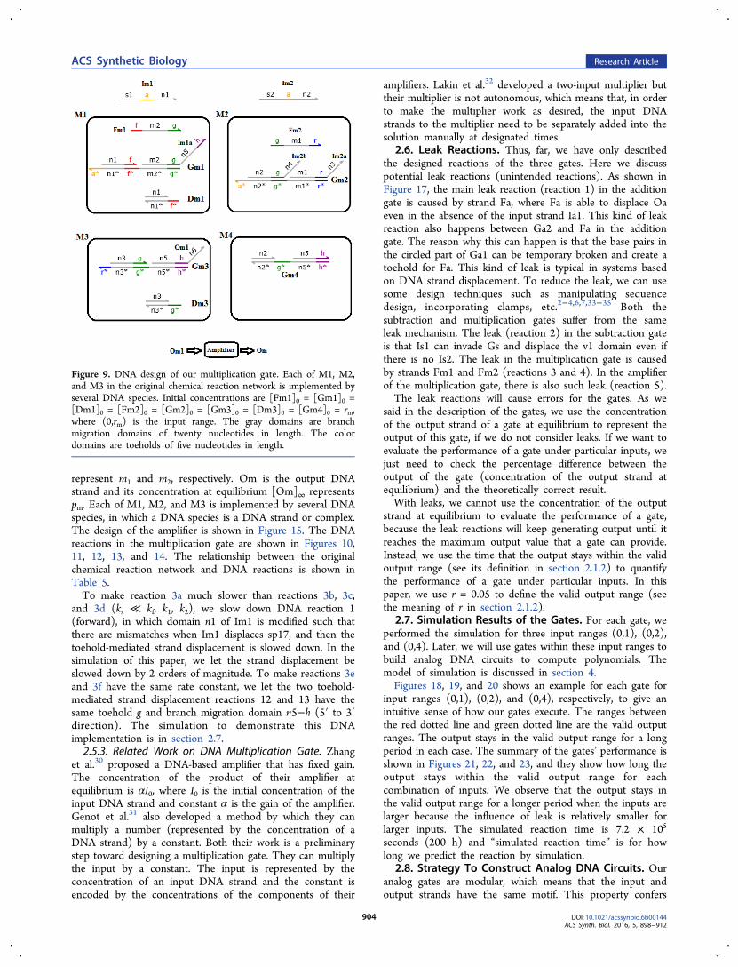
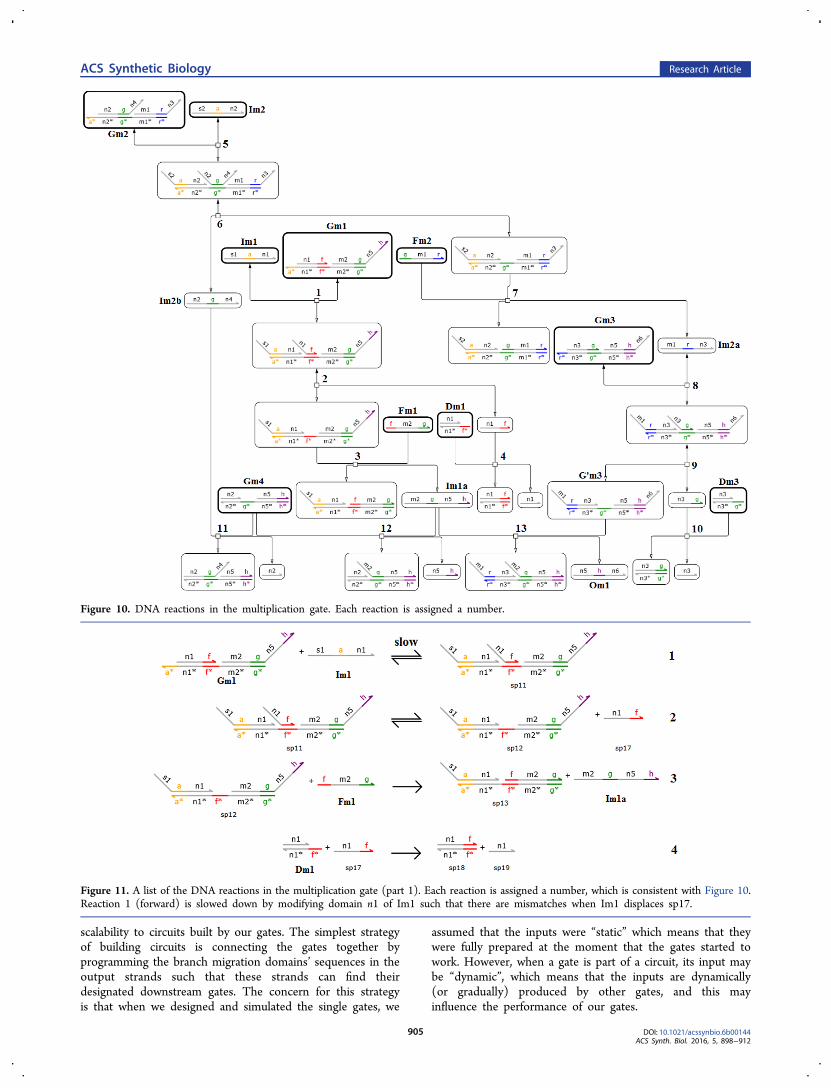
represent m1 and m2, respectively. Om is the output DNAstrand and its concentration at equilibrium [Om]∞ representspm. Each of M1, M2, and M3 is implemented by several DNAspecies, in which a DNA species is a DNA strand or complex.The design of the amplifier is shown in Figure 15. The DNAreactions in the multiplication gate are shown in Figures 10,11, 12, 13, and 14. The relationship between the originalchemical reaction network and DNA reactions is shown inTable 5.To make reaction 3a much slower than reactions 3b, 3c,
and 3d (ks ≪ kf, k1, k2), we slow down DNA reaction 1(forward), in which domain n1 of Im1 is modified such thatthere are mismatches when Im1 displaces sp17, and then thetoehold-mediated strand displacement is slowed down. In thesimulation of this paper, we let the strand displacement beslowed down by 2 orders of magnitude. To make reactions 3eand 3f have the same rate constant, we let the two toehold-mediated strand displacement reactions 12 and 13 have thesame toehold g and branch migration domain n5−h (5′ to 3′direction). The simulation to demonstrate this DNAimplementation is in section 2.7.2.5.3. Related Work on DNA Multiplication Gate. Zhang
et al.30 proposed a DNA-based amplifier that has fixed gain.The concentration of the product of their amplifier atequilibrium is αI0, where I0 is the initial concentration of theinput DNA strand and constant α is the gain of the amplifier.Genot et al.31 also developed a method by which they canmultiply a number (represented by the concentration of aDNA strand) by a constant. Both their work is a preliminarystep toward designing a multiplication gate. They can multiplythe input by a constant. The input is represented by theconcentration of an input DNA strand and the constant isencoded by the concentrations of the components of their
amplifiers. Lakin et al.32 developed a two-input multiplier buttheir multiplier is not autonomous, which means that, in orderto make the multiplier work as desired, the input DNAstrands to the multiplier need to be separately added into thesolution manually at designated times.
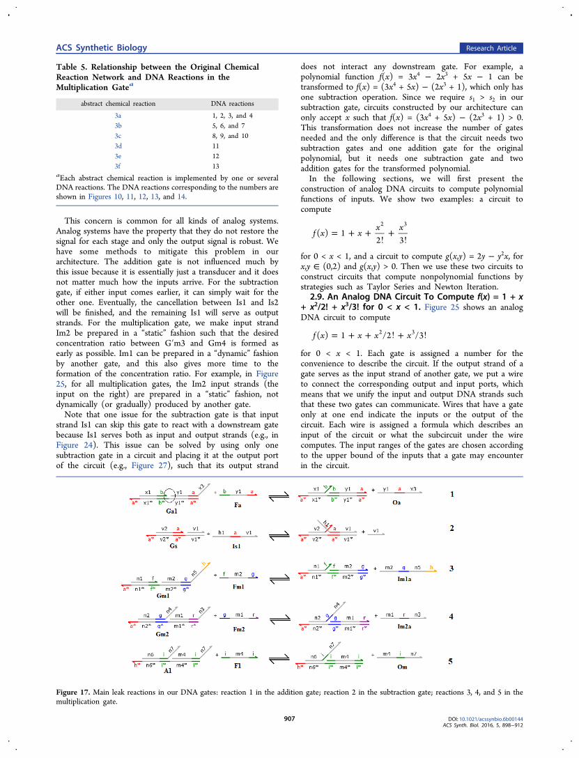
2.6. Leak Reactions. Thus, far, we have only describedthe designed reactions of the three gates. Here we discusspotential leak reactions (unintended reactions). As shown inFigure 17, the main leak reaction (reaction 1) in the additiongate is caused by strand Fa, where Fa is able to displace Oaeven in the absence of the input strand Ia1. This kind of leakreaction also happens between Ga2 and Fa in the additiongate. The reason why this can happen is that the base pairs inthe circled part of Ga1 can be temporary broken and create atoehold for Fa. This kind of leak is typical in systems basedon DNA strand displacement. To reduce the leak, we can usesome design techniques such as manipulating sequencedesign, incorporating clamps, etc.2−4,6,7,33−35 Both thesubtraction and multiplication gates suffer from the sameleak mechanism. The leak (reaction 2) in the subtraction gateis that Is1 can invade Gs and displace the v1 domain even ifthere is no Is2. The leak in the multiplication gate is causedby strands Fm1 and Fm2 (reactions 3 and 4). In the amplifierof the multiplication gate, there is also such leak (reaction 5).The leak reactions will cause errors for the gates. As we
said in the description of the gates, we use the concentrationof the output strand of a gate at equilibrium to represent theoutput of this gate, if we do not consider leaks. If we want toevaluate the performance of a gate under particular inputs, wejust need to check the percentage difference between theoutput of the gate (concentration of the output strand atequilibrium) and the theoretically correct result.With leaks, we cannot use the concentration of the output
strand at equilibrium to evaluate the performance of a gate,because the leak reactions will keep generating output until itreaches the maximum output value that a gate can provide.Instead, we use the time that the output stays within the validoutput range (see its definition in section 2.1.2) to quantifythe performance of a gate under particular inputs. In thispaper, we use r = 0.05 to define the valid output range (seethe meaning of r in section 2.1.2).
2.7. Simulation Results of the Gates. For each gate, weperformed the simulation for three input ranges (0,1), (0,2),and (0,4). Later, we will use gates within these input ranges tobuild analog DNA circuits to compute polynomials. Themodel of simulation is discussed in section 4.Figures 18, 19, and 20 shows an example for each gate for
input ranges (0,1), (0,2), and (0,4), respectively, to give anintuitive sense of how our gates execute. The ranges betweenthe red dotted line and green dotted line are the valid outputranges. The output stays in the valid output range for a longperiod in each case. The summary of the gates’ performance isshown in Figures 21, 22, and 23, and they show how long theoutput stays within the valid output range for eachcombination of inputs. We observe that the output stays inthe valid output range for a longer period when the inputs arelarger because the influence of leak is relatively smaller forlarger inputs. The simulated reaction time is 7.2 × 10⁵
seconds (200 h) and “simulated reaction time” is for howlong we predict the reaction by simulation.
2.8. Strategy To Construct Analog DNA Circuits. Ouranalog gates are modular, which means that the input andoutput strands have the same motif. This property confers
Figure 9. DNA design of our multiplication gate. Each of M1, M2,and M3 in the original chemical reaction network is implemented byseveral DNA species. Initial concentrations are [Fm1]0 = [Gm1]0 =[Dm1]0 = [Fm2]0 = [Gm2]0 = [Gm3]0 = [Dm3]0 = [Gm4]0 = rm,where (0,rm) is the input range. The gray domains are branchmigration domains of twenty nucleotides in length. The colordomains are toeholds of five nucleotides in length.
ACS Synthetic Biology Research Article
DOI: 10.1021/acssynbio.6b00144ACS Synth. Biol. 2016, 5, 898−912
904
scalability to circuits built by our gates. The simplest strategyof building circuits is connecting the gates together byprogramming the branch migration domains’ sequences in theoutput strands such that these strands can find theirdesignated downstream gates. The concern for this strategyis that when we designed and simulated the single gates, we
assumed that the inputs were “static” which means that theywere fully prepared at the moment that the gates started towork. However, when a gate is part of a circuit, its input maybe “dynamic”, which means that the inputs are dynamically(or gradually) produced by other gates, and this mayinfluence the performance of our gates.
Figure 10. DNA reactions in the multiplication gate. Each reaction is assigned a number.
Figure 11. A list of the DNA reactions in the multiplication gate (part 1). Each reaction is assigned a number, which is consistent with Figure 10.Reaction 1 (forward) is slowed down by modifying domain n1 of Im1 such that there are mismatches when Im1 displaces sp17.
ACS Synthetic Biology Research Article
DOI: 10.1021/acssynbio.6b00144ACS Synth. Biol. 2016, 5, 898−912
905

Figure 12. A list of the DNA reactions in the multiplication gate (part 2). Each reaction is assigned a number, which is consistent with Figure 10.
Figure 13. A list of the DNA reactions in the multiplication gate (part 3). Each reaction is assigned a number, which is consistent with Figure 10.
Figure 14. A list of the DNA reactions in the multiplication gate (part 4). Each reaction is assigned a number, which is consistent with Figure 10.
Figure 15. Design of a 2 × amplifier, where one Om1 strandgenerates two Om strands. We can choose rm as a power of 2. For rm= 2n, we just need to connect n layers of such 2× amplifiers in seriesto get a 2n× amplifier. The maximum possible input of layer-0(represented by [Om1]) is = =r 2r r
rn
mm m
mas the calculation in
section 2.3.1 with m1 = m2 = rm. Therefore, the maximum possibleinput of layer i is 2n+i (0 ≤ i ≤ n − 1). In layer i, we let the initialconcentrations of the DNA strand F and the DNA complex A be2n+i, such that the amplifier can afford the maximum possible input.The reactions in the amplifier are shown in Figure 16. The two Omstrands are identical in terms that only the i−n7 (5′ to 3′ direction)part in the two strands matters in further reactions.
Figure 16. DNA reactions in a 2× amplifier.
ACS Synthetic Biology Research Article
DOI: 10.1021/acssynbio.6b00144ACS Synth. Biol. 2016, 5, 898−912
906
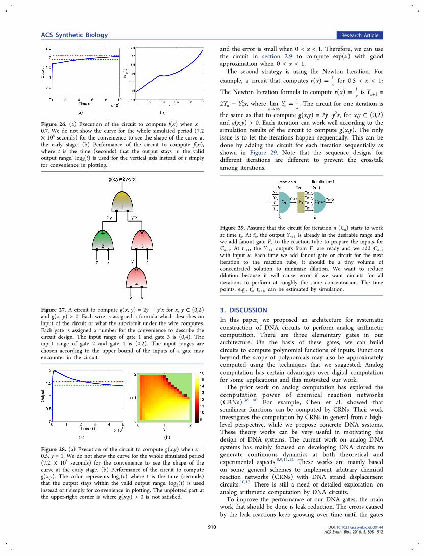
This concern is common for all kinds of analog systems.Analog systems have the property that they do not restore thesignal for each stage and only the output signal is robust. Wehave some methods to mitigate this problem in ourarchitecture. The addition gate is not influenced much bythis issue because it is essentially just a transducer and it doesnot matter much how the inputs arrive. For the subtractiongate, if either input comes earlier, it can simply wait for theother one. Eventually, the cancellation between Is1 and Is2will be finished, and the remaining Is1 will serve as outputstrands. For the multiplication gate, we make input strandIm2 be prepared in a “static” fashion such that the desiredconcentration ratio between G′m3 and Gm4 is formed asearly as possible. Im1 can be prepared in a “dynamic” fashionby another gate, and this also gives more time to theformation of the concentration ratio. For example, in Figure25, for all multiplication gates, the Im2 input strands (theinput on the right) are prepared in a “static” fashion, notdynamically (or gradually) produced by another gate.Note that one issue for the subtraction gate is that input
strand Is1 can skip this gate to react with a downstream gatebecause Is1 serves both as input and output strands (e.g., inFigure 24). This issue can be solved by using only onesubtraction gate in a circuit and placing it at the output portof the circuit (e.g., Figure 27), such that its output strand
does not interact any downstream gate. For example, apolynomial function f(x) = 3x4 − 2x3 + 5x − 1 can betransformed to f(x) = (3x4 + 5x) − (2x3 + 1), which only hasone subtraction operation. Since we require s1 > s2 in oursubtraction gate, circuits constructed by our architecture canonly accept x such that f(x) = (3x4 + 5x) − (2x3 + 1) > 0.This transformation does not increase the number of gatesneeded and the only difference is that the circuit needs twosubtraction gates and one addition gate for the originalpolynomial, but it needs one subtraction gate and twoaddition gates for the transformed polynomial.In the following sections, we will first present the
construction of analog DNA circuits to compute polynomialfunctions of inputs. We show two examples: a circuit tocompute
= + +!
+!
f x xx x
( ) 12 3
2 3
for 0 < x < 1, and a circuit to compute g(x,y) = 2y − y2x, forx,y ∈ (0,2) and g(x,y) > 0. Then we use these two circuits toconstruct circuits that compute nonpolynomial functions bystrategies such as Taylor Series and Newton Iteration.
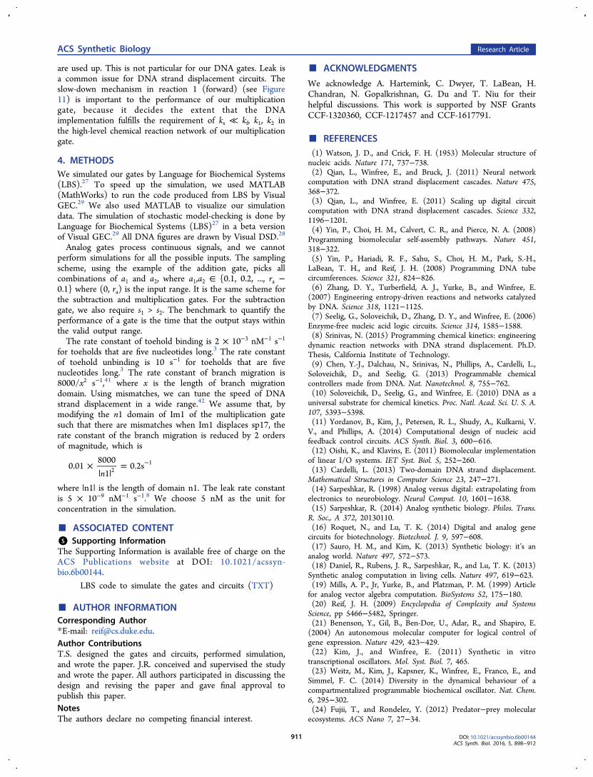
2.9. An Analog DNA Circuit To Compute f(x) = 1 + x+ x2/2! + x3/3! for 0 < x < 1. Figure 25 shows an analogDNA circuit to compute
= + + ! + !f x x x x( ) 1 /2 /32 3
for 0 < x < 1. Each gate is assigned a number for theconvenience to describe the circuit. If the output strand of agate serves as the input strand of another gate, we put a wireto connect the corresponding output and input ports, whichmeans that we unify the input and output DNA strands suchthat these two gates can communicate. Wires that have a gateonly at one end indicate the inputs or the output of thecircuit. Each wire is assigned a formula which describes aninput of the circuit or what the subcircuit under the wirecomputes. The input ranges of the gates are chosen accordingto the upper bound of the inputs that a gate may encounterin the circuit.
Table 5. Relationship between the Original ChemicalReaction Network and DNA Reactions in theMultiplication Gatea
abstract chemical reaction DNA reactions
3a 1, 2, 3, and 43b 5, 6, and 73c 8, 9, and 103d 113e 123f 13
aEach abstract chemical reaction is implemented by one or severalDNA reactions. The DNA reactions corresponding to the numbers areshown in Figures 10, 11, 12, 13, and 14.
Figure 17. Main leak reactions in our DNA gates: reaction 1 in the addition gate; reaction 2 in the subtraction gate; reactions 3, 4, and 5 in themultiplication gate.
ACS Synthetic Biology Research Article
DOI: 10.1021/acssynbio.6b00144ACS Synth. Biol. 2016, 5, 898−912
907
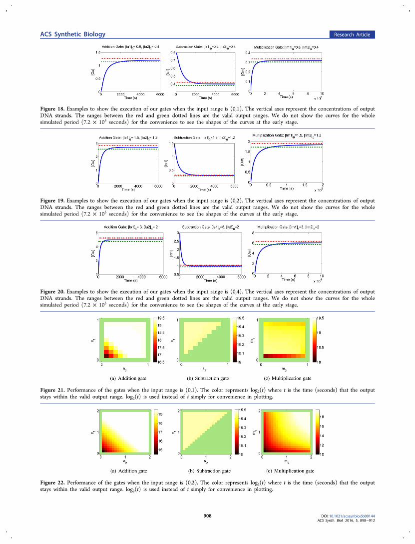
Figure 18. Examples to show the execution of our gates when the input range is (0,1). The vertical axes represent the concentrations of outputDNA strands. The ranges between the red and green dotted lines are the valid output ranges. We do not show the curves for the wholesimulated period (7.2 × 10⁵ seconds) for the convenience to see the shapes of the curves at the early stage.
Figure 19. Examples to show the execution of our gates when the input range is (0,2). The vertical axes represent the concentrations of outputDNA strands. The ranges between the red and green dotted lines are the valid output ranges. We do not show the curves for the wholesimulated period (7.2 × 10⁵ seconds) for the convenience to see the shapes of the curves at the early stage.
Figure 20. Examples to show the execution of our gates when the input range is (0,4). The vertical axes represent the concentrations of outputDNA strands. The ranges between the red and green dotted lines are the valid output ranges. We do not show the curves for the wholesimulated period (7.2 × 10⁵ seconds) for the convenience to see the shapes of the curves at the early stage.
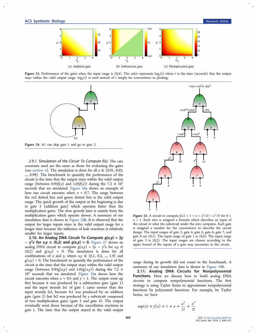
Figure 21. Performance of the gates when the input range is (0,1). The color represents log2(t) where t is the time (seconds) that the outputstays within the valid output range. log2(t) is used instead of t simply for convenience in plotting.
Figure 22. Performance of the gates when the input range is (0,2). The color represents log2(t) where t is the time (seconds) that the outputstays within the valid output range. log2(t) is used instead of t simply for convenience in plotting.
ACS Synthetic Biology Research Article
DOI: 10.1021/acssynbio.6b00144ACS Synth. Biol. 2016, 5, 898−912
908
2.9.1. Simulation of the Circuit To Compute f(x). The rateconstants used are the same as those for evaluating the gates(see section 4). The simulation is done for all x ∈ {0.01, 0.02,..., 0.99}. The benchmark to quantify the performance of thecircuit is the time that the output stays within the valid outputrange (between 0.95f(x) and 1.05f(x)) during the 7.2 × 10⁵
seconds that we simulated. Figure 26a shows an example ofhow our circuit executes when x = 0.7. The range betweenthe red dotted line and green dotted line is the valid outputrange. The quick growth of the output at the beginning is dueto gate 3 (addition gate) which operates faster than themultiplication gates. The slow growth later is mainly from themultiplication gates which operate slower. A summary of oursimulation data is shown in Figure 26b. It is observed that theoutput for larger inputs stays in the valid output range for alonger time because the influence of leak reactions is relativelysmaller for larger inputs.2.10. An Analog DNA Circuit To Compute g(x,y) = 2y
− y2x for x,y ∈ (0,2) and g(x,y) > 0. Figure 27 shows ananalog DNA circuit to compute g(x,y) = 2y − y2x for x,y ∈(0,2) and g(x,y) > 0. The simulation is done for allcombinations of x and y, where x,y ∈ {0.1, 0.2, ..., 1.9} andg(x,y) > 0. The benchmark to quantify the performance of thecircuit is the time that the output stays within the valid outputrange (between 0.95g(x,y) and 1.05g(x,y)) during the 7.2 ×10⁵ seconds that we simulated. Figure 28a shows how thecircuit executes when x = 0.5 and y = 1. The output went upfirst because it was produced by a subtraction gate (gate 1)and the input strands Is1 of gate 1 came sooner than theinput strands Is2, because Is1 was produced by an additiongate (gate 2) but Is2 was produced by a subcircuit composedof two multiplication gates (gate 3 and gate 4). The outputeventually went down because of the cancellation reactions ingate 1. The time that the output stayed in the valid output
range during its growth did not count to the benchmark. Asummary of our simulation data is shown in Figure 28b.
2.11. Analog DNA Circuits for NonpolynomialFunctions. Here we discuss how to build analog DNAcircuits to compute nonpolynomial functions. The firststrategy is using Taylor Series to approximate nonpolynomialfunctions by polynomial functions. For example, by TaylorSeries, we have
≈ = + +!
+!
x f x xx x
exp( ) ( ) 12 3
2 3
Figure 23. Performance of the gates when the input range is (0,4). The color represents log2(t) where t is the time (seconds) that the outputstays within the valid output range. log2(t) is used instead of t simply for convenience in plotting.
Figure 24. Is1 can skip gate 1 and go to gate 2.
Figure 25. A circuit to compute f(x) = 1 + x + x2/2! + x3/3! for 0 <x < 1. Each wire is assigned a formula which describes an input ofthe circuit or what the subcircuit under the wire computes. Each gateis assigned a number for the convenience to describe the circuitdesign. The input ranges of gate 2, gate 4, gate 5, gate 6, gate 7, andgate 8 are (0,1). The input range of gate 1 is (0,4). The input rangeof gate 3 is (0,2). The input ranges are chosen according to theupper bound of the inputs of a gate may encounter in the circuit.
ACS Synthetic Biology Research Article
DOI: 10.1021/acssynbio.6b00144ACS Synth. Biol. 2016, 5, 898−912
909
and the error is small when 0 < x < 1. Therefore, we can usethe circuit in section 2.9 to compute exp(x) with goodapproximation when 0 < x < 1.The second strategy is using the Newton Iteration. For
example, a circuit that computes =r x( )x1 for 0.5 < x < 1:
The Newton Iteration formula to compute =r x( )x1 is Yn+1 =
2Yn − Yn2x, where =
→∞Ylim
nn x
1 . The circuit for one iteration is
the same as that to compute g(x,y) = 2y−y2x, for x,y ∈ (0,2)and g(x,y) > 0. Each iteration can work well according to thesimulation results of the circuit to compute g(x,y). The onlyissue is to let the iterations happen sequentially. This can bedone by adding the circuit for each iteration sequentially asshown in Figure 29. Note that the sequence designs fordifferent iterations are different to prevent the crosstalkamong iterations.
3. DISCUSSIONIn this paper, we proposed an architecture for systematicconstruction of DNA circuits to perform analog arithmeticcomputation. There are three elementary gates in ourarchitecture. On the basis of these gates, we can buildcircuits to compute polynomial functions of inputs. Functionsbeyond the scope of polynomials may also be approximatelycomputed using the techniques that we suggested. Analogcomputation has certain advantages over digital computationfor some applications and this motivated our work.The prior work on analog computation has explored the
computation power of chemical reaction networks(CRNs).36−40 For example, Chen et al. showed thatsemilinear functions can be computed by CRNs. Their workinvestigates the computation by CRNs in general from a high-level perspective, while we propose concrete DNA systems.These theory works can be very useful in motivating thedesign of DNA systems. The current work on analog DNAsystems has mainly focused on developing DNA circuits togenerate continuous dynamics at both theoretical andexperimental aspects.8,9,11,12 These works are mainly basedon some general schemes to implement arbitrary chemicalreaction networks (CRNs) with DNA strand displacementcircuits.10,13 There is still a need of detailed exploration onanalog arithmetic computation by DNA circuits.To improve the performance of our DNA gates, the main
work that should be done is leak reduction. The errors causedby the leak reactions keep growing over time until the gates
Figure 26. (a) Execution of the circuit to compute f(x) when x =0.7. We do not show the curve for the whole simulated period (7.2× 10⁵ seconds) for the convenience to see the shape of the curve atthe early stage. (b) Performance of the circuit to compute f(x),where t is the time (seconds) that the output stays in the validoutput range. log2(t) is used for the vertical axis instead of t simplyfor convenience in plotting.
Figure 27. A circuit to compute g(x, y) = 2y − y2x for x, y ∈ (0,2)and g(x, y) > 0. Each wire is assigned a formula which describes aninput of the circuit or what the subcircuit under the wire computes.Each gate is assigned a number for the convenience to describe thecircuit design. The input range of gate 1 and gate 3 is (0,4). Theinput range of gate 2 and gate 4 is (0,2). The input ranges arechosen according to the upper bound of the inputs of a gate mayencounter in the circuit.
Figure 28. (a) Execution of the circuit to compute g(x,y) when x =0.5, y = 1. We do not show the curve for the whole simulated period(7.2 × 10⁵ seconds) for the convenience to see the shape of thecurve at the early stage. (b) Performance of the circuit to computeg(x,y). The color represents log2(t) where t is the time (seconds)that the output stays within the valid output range. log2(t) is usedinstead of t simply for convenience in plotting. The unplotted part atthe upper-right corner is where g(x,y) > 0 is not satisfied.
Figure 29. Assume that the circuit for iteration n (Cn) starts to workat time tn. At tn′, the output Yn+1 is already in the desirable range andwe add fanout gate Fn to the reaction tube to prepare the inputs forCn+1. At tn+1, the Yn+1 outputs from Fn are ready and we add Cn+1with input x. Each time we add fanout gate or circuit for the nextiteration to the reaction tube, it should be a tiny volume ofconcentrated solution to minimize dilution. We want to reducedilution because it will cause error if we want circuits for alliterations to perform at roughly the same concentration. The timepoints, e.g., tn′, tn+1, can be estimated by simulation.
ACS Synthetic Biology Research Article
DOI: 10.1021/acssynbio.6b00144ACS Synth. Biol. 2016, 5, 898−912
910
are used up. This is not particular for our DNA gates. Leak isa common issue for DNA strand displacement circuits. Theslow-down mechanism in reaction 1 (forward) (see Figure11) is important to the performance of our multiplicationgate, because it decides the extent that the DNAimplementation fulfills the requirement of ks ≪ kf, k1, k2 inthe high-level chemical reaction network of our multiplicationgate.
4. METHODSWe simulated our gates by Language for Biochemical Systems(LBS).27 To speed up the simulation, we used MATLAB(MathWorks) to run the code produced from LBS by VisualGEC.29 We also used MATLAB to visualize our simulationdata. The simulation of stochastic model-checking is done byLanguage for Biochemical Systems (LBS)27 in a beta versionof Visual GEC.29 All DNA figures are drawn by Visual DSD.28
Analog gates process continuous signals, and we cannotperform simulations for all the possible inputs. The samplingscheme, using the example of the addition gate, picks allcombinations of a1 and a2, where a1,a2 ∈ {0.1, 0.2, ..., ra −0.1} where (0, ra) is the input range. It is the same scheme forthe subtraction and multiplication gates. For the subtractiongate, we also require s1 > s2. The benchmark to quantify theperformance of a gate is the time that the output stays withinthe valid output range.The rate constant of toehold binding is 2 × 10⁻³ nM−1 s−1
for toeholds that are five nucleotides long.3 The rate constantof toehold unbinding is 10 s−1 for toeholds that are fivenucleotides long.3 The rate constant of branch migration is8000/x2 s−1,41 where x is the length of branch migrationdomain. Using mismatches, we can tune the speed of DNAstrand displacement in a wide range.42 We assume that, bymodifying the n1 domain of Im1 of the multiplication gatesuch that there are mismatches when Im1 displaces sp17, therate constant of the branch migration is reduced by 2 ordersof magnitude, which is
×| |
= −
n0.01
80001
0.2s21
where |n1| is the length of domain n1. The leak rate constantis 5 × 10⁻⁹ nM−1 s−1.8 We choose 5 nM as the unit forconcentration in the simulation.
■ ASSOCIATED CONTENT*S Supporting InformationThe Supporting Information is available free of charge on theACS Publications website at DOI: 10.1021/acssyn-bio.6b00144.
LBS code to simulate the gates and circuits (TXT)
■ AUTHOR INFORMATIONCorresponding Author*E-mail: [email protected] ContributionsT.S. designed the gates and circuits, performed simulation,and wrote the paper. J.R. conceived and supervised the studyand wrote the paper. All authors participated in discussing thedesign and revising the paper and gave final approval topublish this paper.NotesThe authors declare no competing financial interest.
■ ACKNOWLEDGMENTS
We acknowledge A. Hartemink, C. Dwyer, T. LaBean, H.Chandran, N. Gopalkrishnan, G. Du and T. Niu for theirhelpful discussions. This work is supported by NSF GrantsCCF-1320360, CCF-1217457 and CCF-1617791.
■ REFERENCES(1) Watson, J. D., and Crick, F. H. (1953) Molecular structure ofnucleic acids. Nature 171, 737−738.(2) Qian, L., Winfree, E., and Bruck, J. (2011) Neural networkcomputation with DNA strand displacement cascades. Nature 475,368−372.(3) Qian, L., and Winfree, E. (2011) Scaling up digital circuitcomputation with DNA strand displacement cascades. Science 332,1196−1201.(4) Yin, P., Choi, H. M., Calvert, C. R., and Pierce, N. A. (2008)Programming biomolecular self-assembly pathways. Nature 451,318−322.(5) Yin, P., Hariadi, R. F., Sahu, S., Choi, H. M., Park, S.-H.,LaBean, T. H., and Reif, J. H. (2008) Programming DNA tubecircumferences. Science 321, 824−826.(6) Zhang, D. Y., Turberfield, A. J., Yurke, B., and Winfree, E.(2007) Engineering entropy-driven reactions and networks catalyzedby DNA. Science 318, 1121−1125.(7) Seelig, G., Soloveichik, D., Zhang, D. Y., and Winfree, E. (2006)Enzyme-free nucleic acid logic circuits. Science 314, 1585−1588.(8) Srinivas, N. (2015) Programming chemical kinetics: engineeringdynamic reaction networks with DNA strand displacement. Ph.D.Thesis, California Institute of Technology.(9) Chen, Y.-J., Dalchau, N., Srinivas, N., Phillips, A., Cardelli, L.,Soloveichik, D., and Seelig, G. (2013) Programmable chemicalcontrollers made from DNA. Nat. Nanotechnol. 8, 755−762.(10) Soloveichik, D., Seelig, G., and Winfree, E. (2010) DNA as auniversal substrate for chemical kinetics. Proc. Natl. Acad. Sci. U. S. A.107, 5393−5398.(11) Yordanov, B., Kim, J., Petersen, R. L., Shudy, A., Kulkarni, V.V., and Phillips, A. (2014) Computational design of nucleic acidfeedback control circuits. ACS Synth. Biol. 3, 600−616.(12) Oishi, K., and Klavins, E. (2011) Biomolecular implementationof linear I/O systems. IET Syst. Biol. 5, 252−260.(13) Cardelli, L. (2013) Two-domain DNA strand displacement.Mathematical Structures in Computer Science 23, 247−271.(14) Sarpeshkar, R. (1998) Analog versus digital: extrapolating fromelectronics to neurobiology. Neural Comput. 10, 1601−1638.(15) Sarpeshkar, R. (2014) Analog synthetic biology. Philos. Trans.R. Soc., A 372, 20130110.(16) Roquet, N., and Lu, T. K. (2014) Digital and analog genecircuits for biotechnology. Biotechnol. J. 9, 597−608.(17) Sauro, H. M., and Kim, K. (2013) Synthetic biology: it’s ananalog world. Nature 497, 572−573.(18) Daniel, R., Rubens, J. R., Sarpeshkar, R., and Lu, T. K. (2013)Synthetic analog computation in living cells. Nature 497, 619−623.(19) Mills, A. P., Jr, Yurke, B., and Platzman, P. M. (1999) Articlefor analog vector algebra computation. BioSystems 52, 175−180.(20) Reif, J. H. (2009) Encyclopedia of Complexity and SystemsScience, pp 5466−5482, Springer.(21) Benenson, Y., Gil, B., Ben-Dor, U., Adar, R., and Shapiro, E.(2004) An autonomous molecular computer for logical control ofgene expression. Nature 429, 423−429.(22) Kim, J., and Winfree, E. (2011) Synthetic in vitrotranscriptional oscillators. Mol. Syst. Biol. 7, 465.(23) Weitz, M., Kim, J., Kapsner, K., Winfree, E., Franco, E., andSimmel, F. C. (2014) Diversity in the dynamical behaviour of acompartmentalized programmable biochemical oscillator. Nat. Chem.6, 295−302.(24) Fujii, T., and Rondelez, Y. (2012) Predator−prey molecularecosystems. ACS Nano 7, 27−34.
ACS Synthetic Biology Research Article
DOI: 10.1021/acssynbio.6b00144ACS Synth. Biol. 2016, 5, 898−912
911
(25) Elowitz, M. B., and Leibler, S. (2000) A synthetic oscillatorynetwork of transcriptional regulators. Nature 403, 335−338.(26) McMillen, D., Kopell, N., Hasty, J., and Collins, J. (2002)Synchronizing genetic relaxation oscillators by intercell signaling.Proc. Natl. Acad. Sci. U. S. A. 99, 679−684.(27) Pedersen, M., and Plotkin, G. D. (2010) Transactions onComputational Systems Biology XII, pp 77−145, Springer, Berlin,Heidelberg.(28) Lakin, M. R., Youssef, S., Polo, F., Emmott, S., and Phillips, A.(2011) Visual DSD: a design and analysis tool for DNA stranddisplacement systems. Bioinformatics 27, 3211−3213.(29) Pedersen, M., and Phillips, A. (2009) Towards programminglanguages for genetic engineering of living cells. J. R. Soc., Interface 6,S437−S450.(30) Zhang, D. Y., and Seelig, G. (2011) DNA Computing andMolecular Programming, pp 176−186, Springer, Berlin, Heidelberg.(31) Genot, A. J., Bath, J., and Turberfield, A. J. (2013)Combinatorial displacement of DNA strands: application to matrixmultiplication and weighted sums. Angew. Chem., Int. Ed. 52, 1189−1192.(32) Lakin, M. R., and Stefanovic, D. (2015) Proceedings of the 21stInternational Conference on DNA Computing and Molecular Program-ming 9211, 154−167.(33) Qian, L., and Winfree, E. (2009) DNA Computing andMolecular Programming, pp 70−89, Springer, Berlin, Heidelberg.(34) Qian, L., and Winfree, E. (2011) A simple DNA gate motif forsynthesizing large-scale circuits. J. R. Soc., Interface 8, 1281−1297.(35) Zhang, D. Y. (2011) DNA Computing and MolecularProgramming, pp 162−175, Springer, Berlin, Heidelberg.(36) Soloveichik, D., Cook, M., Winfree, E., and Bruck, J. (2008)Computation with finite stochastic chemical reaction networks. Nat.Comput. 7, 615−633.(37) Cook, M., Soloveichik, D., Winfree, E., and Bruck, J. (2009)Algorithmic Bioprocesses, pp 543−584, Springer.(38) Chen, H.-L., Doty, D., and Soloveichik, D. (2014) Rate-independent computation in continuous chemical reaction networks.Proceedings of the 5th Conference on Innovations in TheoreticalComputer Science, pp 313−326, Association for ComputingMachinery.(39) Cummings, R., Doty, D., and Soloveichik, D. (2014) DNAComputing and Molecular Programming, pp 37−52, Springer.(40) Jiang, H., Riedel, M. D., and Parhi, K. K. (2011)Asynchronous computation with molecular reactions. ConferenceRecord of the Forty Fifth Asilomar Conference on Signals, Systemsand Computers (ASILOMAR), pp 493−497.(41) Zhang, D. Y., and Winfree, E. (2009) Control of DNA stranddisplacement kinetics using toehold exchange. J. Am. Chem. Soc. 131,17303−17314.(42) Machinek, R. R., Ouldridge, T. E., Haley, N. E., Bath, J., andTurberfield, A. J. (2014) Programmable energy landscapes for kineticcontrol of DNA strand displacement. Nat. Commun. 5, 5324.
ACS Synthetic Biology Research Article
DOI: 10.1021/acssynbio.6b00144ACS Synth. Biol. 2016, 5, 898−912
912