Embed Size (px)
Citation preview
232 Revista Română de Materiale / Romanian Journal of Materials 2016, 46 (2),232 -241
ANALIZA COMPARATIVĂ A CONSTANTELOR ELASTICE INGINEREȘTI ALE STRATIFICATELOR COMPOZITE
COMPARATIVE ANALYSIS OF THE ENGINEERING CONSTANTS
OF COMPOSITE LAMINATES
IULIANA HUDIȘTEANU, NICOLAE ȚĂRANU , IOANA-SORINA ENȚUC, SEBASTIAN GEORGE MAXINEASA “Gheorghe Asachi” Technical University of Iaşi, 43 Mangeron Blvd., Iaşi, Romania, 700050
Composite structures subjected to complex states
of stresses require tailored strength and stiffness characteristics in certain directions, while the properties of the unidirectional lamina are disproportioned and unequal in different directions. Therefore, a multi-layered composite is needed, with various stacking sequences of elementary laminas and different fibre orientations. An accurate prediction of the elastic engineering constants is essential, in order to evaluate the stiffness properties of composite laminates.
The paper presents a comparative analysis of the in-plane elastic engineering constants of continuous fibre reinforced laminated composites, pointing out the influencing parameters of the stiffness properties of multi-layered composites. Three types of laminates, made of composite laminas reinforced with S glass fibres or E glass fibres, embedded in an epoxy resin, with different geometric arrangements of laminas are analysed: an asymmetric general laminate, an anti-symmetric angle-ply and a symmetric angle-ply laminate. The obtained results, illustrated by the graphical distributions of the engineering constants, reveal superior stiffness properties in case of particular laminates.
Structurile compozite solicitate la stări complexe
de tensiuni necesită caracteristici de rezistență și rigiditate dirijate după anumite direcții, în timp ce proprietățile unei lamele armate unidirecțional sunt disproporționate și inegale pe direcții diferite. Din acest motiv, este necesară alcătuirea unor structuri compozite stratificate cu anumite succesiuni ale straturilor elementare și diferite orientări ale fibrelor. O cunoaștere precisă a constantelor elastice inginerești este esențială, pentru o evaluare a caracteristicilor de rigiditate ale stratificatelor compozite.
Lucrarea prezintă o analiză comparativă a constantelor elastice inginerești în planul unor stratificate compozite armate cu fibre continue, evidențiind parametrii ce influențează caracteristicile de rigiditate ale acestora. Sunt analizate trei tipuri de stratificate, realizate din lamele compozite armate cu fibre de sticlă S sau fibre de sticlă E, înglobate în rășină epoxidică, cu diferite configurații geometrice: un stratificat general asimetric, un stratificat unghiular antisimetric și un stratificat unghiular simetric. Rezultatele obținute, reprezentate prin distribuția grafică a constantelor inginerești, evidențiază caracteristici de rigiditate ridicate în cazul stratificatelor particulare.
Keywords: in-plane engineering constants, composite laminates, fibre orientation, glass fibres
1. Introduction
Fibre reinforced polymeric (FRP) composites are widely used structural materials, having strong directional properties, mainly in case of continuous fibres. Due to their remarkable properties, they are utilised in various applications, such as construction, automotive, marine, electrical, aerospace, oil and gas industries [1, 2].
The plurality of fibrous composites advantages, such as the outstanding mechanical properties, high strength related to the lightweight, tailoring of performance, flexibility in design, corrosion resistance, the improved fatigue strength, have led to an increasing utilisation in load-bearing structures [1].
A composite lamina is the simplest element of a composite material, an elementary layer or a building block for multi-layered or composite
laminates. It consists of a thin ply of composite material, generally realized of parallel fibres embedded in a matrix [3]. The stiffness of unidirectional lamina in transverse direction is very poor compared to the longitudinal one, because the matrix properties dominate [4]. Therefore, a laminate is formed by stacking two or more laminas with different fibre orientation angles, in the direction of the lamina thickness [5].
The glass fibres, which are the most frequently utilised reinforcing fibres due to their relative low cost, attain high strength as a result of the low number and size of defects on the fibre surface. For structural FRP composites use, the most commonly types of glass fibres are S-glass and E-glass, in case of elements with load bearing structural, strengthening and electrical purposes [6-9]. Although glass fibres develop high tensile strength, chemical resistance and good impact
Autor corespondent/Corresponding author,
E-mail: [email protected]

I.Hudișteanu, N. Țăranu, I-S. Ențuc, S.G. Maxineasa / Analiza comparativă a constantelor elastice inginerești 233 ale stratificatelor compozite
strength, they have low fatigue resistance, poor adhesion with polymers and relatively low modulus of elasticity [10-13].
Epoxy resins are thermosets with excellent processability and good electrical insulating properties, widely used in structural adhesives, surface coatings, but also as a matrix for high-strength engineering composites and structural laminates [14].
An accurate prediction of the in-plane elastic engineering constants is needed, in order to characterize the stiffness behaviour of laminated composites. The elastic properties of multi-layered composites are influenced by the constituent material characteristics, orientation and location of the individual unidirectional laminas [15, 16].
2. Stiffness properties of laminated structures
made of FRP composites In order to apply the lamination theory
predictions for the macroscopic evaluation of the stiffness properties of multi-layered composites, several aspects regarding micromechanics of orthotropic lamina are needed. Therefore, the specially orthotropic lamina, illustrated in Figure 1, is defined as an elementary thin layer of composite material, with the principal material axes (1, 2) identical with the general system of axes (x, y).
Fig. 1 - The specially orthotropic lamina / Lamela ortotropă
specială.
The analysis of composite laminates is realized in a similar manner as in strength of materials, by establishing a constitutive relationship between stress and strain, according to Hooke’s law [17]. The constitutive equations which describe the linear-elastic response of the specially orthotropic lamina is given in Eq. (1a) [18]:
Q , (1a)
or in the expanded form in Eq. (1b):
12
2
1
66
2212
1211
12
2
1
00
0
0
Q
, (1b)
where:
Q is the reduced stiffness matrix;
1 , 2 , 12 are the in-plane stress components with
respect to the principal material directions;
1 , 2 , 12 are the in-plane strain components with
respect to the principal material directions. The elements i jQ of the stiffness matrix are
expressed in terms of the engineering constants of the lamina, with respect to principal material directions, as follows [19]:
2112
111
1
EQ
2112
212
2112
12112
11
EEQ (2)
2112
222
1
EQ 1266 GQ ,
where:
1E , 2E , 12G are the axial and shear elastic moduli
along the principal material axes;
12 , 21 are the Poisson’s ratios referring to the
axes 1 and 2. The generally orthotropic lamina, shown in
Figure 2, also called the off-axis unidirectional lamina, makes a fibre orientation angle θ with respect to the arbitrary system of axes (x, y).
Fig. 2 - The generally orthotropic lamina / Lamela ortotropă
generală.
The constitutive equation which describes
the relationship between stresses and strains for a generally orthotropic lamina, is given by the condensed form in Eq. (3a) [18]:
Q , (3a)
or in the expanded form in Eq. (3b):
xy
y
x
xy
y
x
QQQ
QQQ
QQQ
662616
262212
161211
, (3b)
where:
Q is the transformed reduced stiffness matrix;
x , y , xy are the in-plane stress components
along the global reference axes;
x , y , xy are the in-plane strain components
along the global reference axes.
The terms i jQ of the transformed reduced
stiffness matrix are expressed in Eq. (4), as follows [20]

234 I.Hudișteanu, N. Țăranu, I-S. Ențuc, S.G. Maxineasa / Comparative analysis of the engineering constants of composite laminates
422
226612
41111 22 sQscQQcQQ
4412
2266221112 4 scQscQQQQ
422
226612
41122 22 cQscQQsQQ
csQ2QQ
scQ2QQQ
3662212
366121116
(4)
3662212
366121126 22 scQQQcsQQQQ
4466
226612221166 22 scQscQQQQQ ,
where: cosc , sins .
Because the fibre contribution to the transverse stiffness of the unidirectional lamina is less compared to that in the longitudinal direction, it is necessary to add laminas with various orientations in the thickness direction, in order to satisfy the design requirements [21]. Therefore, laminates are conceived and designed from unidirectional composite laminas as to improve the directional properties and satisfy the design needs of specific composite structures [1, 22].
The general laminates consist of an arbitrary number of layers stacked and bonded together, oriented in the desired direction [21, 23]. The angle-ply laminate is a particular case of the specially orthotropic laminate, obtained by alternating equal number of layers with +θ and –θ fibre orientation angles, with same thickness and material properties [17, 24].
Symmetric laminates have identical layers in thickness, fibre orientation and material, symmetrically disposed with respect to the middle plane [24]. Reversely, the anti-symmetric laminates are identified by having plies arranged in an anti-symmetrical way about the mid-surface [17].
The geometrical characteristics for a general laminated composite having n layers and 2H thickness are illustrated in Figure 3:
Fig. 3 - Geometrical characteristics of a n-layered laminate Caracteristici geometrice ale unui stratificat cu n straturi.
The constitutive equation which describes the relationship between stresses and strains in a multi-layered laminate is written for an elementary layer k of a generally orthotropic lamina, given by the condensed form in Eq. (5a) [24]:
kkk Q , (5a)
or in the expanded form in Eq. (5b):
kxy
y
x
kkxy
y
x
QQQ
QQQ
QQQ
662616
262212
161211
, (5b)
The resultant in-plane forces ( xN , yN , xyN )
and moments ( xM , yM , xyM ) acting on the middle
plane of the laminated composite is shown in Figure 4.
The force-deformation and moment-deformation relations of multi-layered laminates are described by Eq. (6a) and (6b):
xy
y
x
662616
262212
161211
0xy
0y
0x
662616
262212
161211
xy
y
x
k
k
k
BBB
BBB
BBB
AAA
AAA
AAA
N
N
N
, (6a)
Fig. 4 - In-plane forces and moments per unit width / Forțe și momente pe unitatea de lățime.
I.Hudișteanu, N. Țăranu, I-S. Ențuc, S.G. Maxineasa / Analiza comparativă a constantelor elastice inginerești 235 ale stratificatelor compozite
xy
y
x
662616
262212
161211
0xy
0y
0x
662616
262212
161211
xy
y
x
k
k
k
DDD
DDD
DDD
BBB
BBB
BBB
M
M
M
, (6b)
where:
( 0x ,
0y ,
0xy ) represents the laminate mid-plane
strains;
( xk , yk , xyk ) represents the laminate curvatures;
The contribution of the geometric configuration of the fibres orientation and the stacking sequence on the laminate elastic behaviour is expressed through the matrix terms [A], [B], [D], involved in the force-deformation and moment-deformation relations and discussed below [15, 25].
The extensional stiffness matrix or the in-plane stiffness matrix [A] relates the resultant in-plane forces to the in-plane strains and it can be evaluated with Eq. (7a) or (7b), as follows [10, 26]:
1kk
n
1kkiji j zzQA
, (7a)
662616
262212
161211
1
662616
262212
161211
1
AAA
AAA
AAA
dz
QQQ
QQQ
QQQ
Ak
k
z
z
k
n
k
(7b)
where:
kz , 1kz are the coordinates to the bottom and to the
top of the k layer. The bending-stretching coupling matrix [B]
importance is referred to the coupling effect between forces and moments to the middle plane strains and middle plane curvatures. Matrix [B] is determined according to Eq. (8a) or (8b) [5, 24]:
21k
2k
k
n
1kiji j zzQ
2
1B
, (8a)
662616
262212
161211
1
662616
262212
161211
1
BBB
BBB
BBB
zdz
QQQ
QQQ
QQQ
Bk
k
z
z
k
n
k
(8b)
The bending stiffness matrix [D] relates the resultant bending moments to the plate curvatures [5, 24] and it is expressed as follows:
31k
3k
k
n
1kiji j zzQ
3
1D
, (9a)
662616
262212
161211
2
1
662616
262212
161211
1
DDD
DDD
DDD
dzz
QQQ
QQQ
QQQ
Dk
k
z
z
k
n
k
(9b)
The various coupling effects in laminated composites can be minimized or eliminated through suitable choices of the laminas stacking sequences. The mid-plane symmetry arrangements eliminate the bending-stretching coupling [15]. In case of angle-ply laminate, the D16 and D26 terms can be diminished by increasing the number of unidirectional laminas.
The in-plane engineering constants of laminated composites are determined for the given conditions in Eq. (10), such that the non-zero stresses corresponds to the elastic constants in the needed directions.
0x
xxE
, when 0x , 0y , 0xy ,
0y
y
yE
, when 0y , 0x , 0xy ,
0xy
xy
xyG
, when 0xy , 0x , 0y ,
(10)
0
0
x
yxy
, when 0x , 0y , 0xy ,
0
0
y
xyx
, when 0y , 0x , 0xy .
In case of the in-plane Poisson’s ratio, νxy,
both longitudinal strain 0x and transverse strain
0y
must be written in terms of an applied stress in the x-direction, while in case of the in-plane Poisson’s
ratio, νyx, both longitudinal strain 0y and the
transverse strain 0x will be evaluated in terms of an
applied stress in the y-direction. The development of the explicit relations,
which describe the in-plane elastic characteristics of multi-layered composites, is related to [A], [B], [D] matrices, taking account of stress-strain relationships [27].

236 I.Hudișteanu, N. Țăranu, I-S. Ențuc, S.G. Maxineasa / Comparative analysis of the engineering constants of composite laminates
H
DDDBB
DDDBB
DDDBB
BBBAA
BBBAA
DDDBBB
DDDBBB
DDDBBB
BBBAAA
BBBAAA
BBBAAA
E x2
1
6626166626
2622122622
1612111612
6626166626
2622122622
662616662616
262212262212
161211161211
662616662616
262212262212
161211161211
(11a)
H
DDDBB
DDDBB
DDDBB
BBBAA
BBBAA
DDDBBB
DDDBBB
DDDBBB
BBBAAA
BBBAAA
BBBAAA
Ey2
1
6626166616
2622122612
1612111611
6626166616
1612111611
662616662616
262212262212
161211161211
662616662616
262212262212
161211161211
(11b)
H
DDDBB
DDDBB
DDDBB
BBBAA
BBBAA
DDDBBB
DDDBBB
DDDBBB
BBBAAA
BBBAAA
BBBAAA
Gxy2
1
6626162616
2622122212
1612111211
2622122212
1612111211
662616662616
262212262212
161211161211
662616662616
262212262212
161211161211
(11c)
6626166626
2622122622
1612111612
6626166626
2622122622
6626166616
2622122612
1612111611
6626166616
2622122612
DDDBB
DDDBB
DDDBB
BBBAA
BBBAA
DDDBB
DDDBB
DDDBB
BBBAA
BBBAA
xy (11d)
6626166616
2622122612
1612111611
6626166616
1612111611
6626166626
2622122622
1612111612
6626166626
1612111612
DDDBB
DDDBB
DDDBB
BBBAA
BBBAA
DDDBB
DDDBB
DDDBB
BBBAA
BBBAA
yx (11e)
where: 2H represents the total thickness of the laminate. 3. Case studies
For an accurate prediction of the elastic
engineering constants for multi-layered composites, a comparative analysis is performed according to the classical lamination theory. The study is carried out for three different geometric arrangements of laminas, with 4 layers and the same ply thickness, t=0.4 mm, resulting in the following configurations:
a general laminate 2/ , an anti-symmetric
angle-ply laminate 2 and a symmetric angle-
ply laminate s . The analysis is materialized
through the variations of the in-plane elastic engineering constants with respect to fiber orientation angles, for three selected fibre volume fractions. The composite material properties are given in Table 1 [19], the laminates being made alternatively of S glass or E glass fibres and epoxy resin.
The implication of the [A], [B], [D] matrices on the elastic behaviour of laminates, influenced by the orientation of fibres and stacking sequences, can be observed in Table 2, for both types of glass fibres.
The differences between the analysed laminates can be firstly observed from the corresponding [A], [B], [D] matrices, involved subsequently in the engineering constants graphics. It can be noticed that for the general
laminate, 2/ , the in-plane extensional and
the shear coupling occurs, because of the nonzero
A16 and A26 terms. As expected, both 2 and
s angle-ply configurations are specially
orthotropic laminates, proven by 02616 AA .
Moreover, the requirement that 02616 DD has
no need to be fulfilled in case of specially orthotropic multi-layered composites, since they are distinguished by the in-plane response and not by the bending response. However, the D16 and
I.Hudișteanu, N. Țăranu, I-S. Ențuc, S.G. Maxineasa / Analiza comparativă a constantelor elastice inginerești 237 ale stratificatelor compozite
Table 1
Mechanical characteristics of constituent materials / Caracteristicile mecanice ale materialelor constituente
Constituents of the composite laminas Materialele constituente ale lamelei compozite
Longitudinal Young’s modulus Modulul de elasticitate
longitudinal [GPa]
Poisson’s ratio Coeficientul lui Poisson
S glass fibres / fibre de sticlă S 85.5 0.22
E glass fibres / fibre de sticlă E 72.4 0.22
epoxy resin matrix / matrice din rășină epoxidică 4.1 0.4
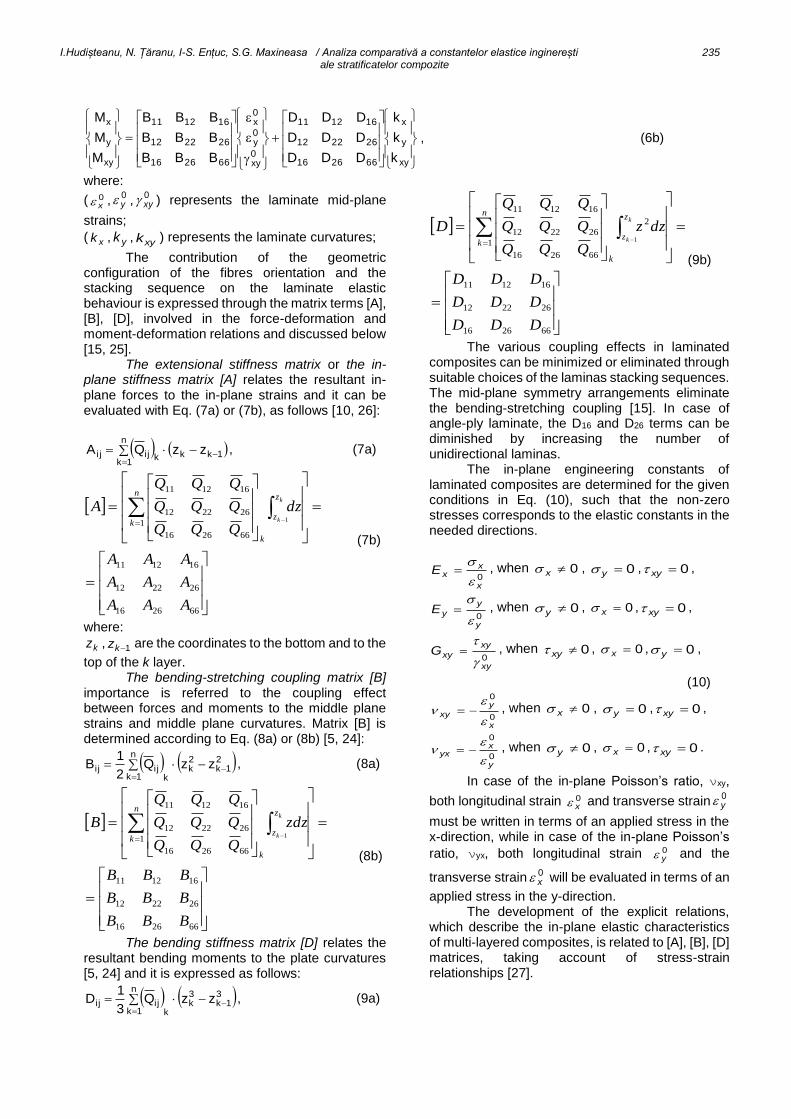
Table 2
[A], [B], [D] stiffness matrices for θ= 45o and Vf = 70% / Matricile de rigiditate [A], [B], [D] pentru θ= 45o și Vf = 70%
S glass fibres and epoxy resin / fibre de sticlă S și matrice epoxidică
[A] [B] [D]
2/
30.2043.743.7
43.754.2925.19
43.725.1954.29
[GPa.mm]
012.112.1
12.100
12.100
[GPa.mm2]
44.256.156.1
56.155.331.2
56.131.255.3
[GPa.mm3]
2
30.2000
054.2925.19
025.1954.29
[GPa.mm]
023.223.2
23.200
23.200
[GPa.mm2]
44.200
055.331.2
031.255.3
[GPa.mm3]
s
30.2000
054.2925.19
025.1954.29
[GPa.mm]
000
000
000
[GPa.mm2]
44.234.134.1
34.155.331.2
34.131.255.3
[GPa.mm3]
E glass fibres and epoxy resin / fibre de sticlă E și matrice epoxidică
[A] [B] [D]
2/
51.1708.608.6
08.661.2653.16
08.653.1661.26
[GPa.mm]
091.091.0
91.000
91.000
[GPa.mm2]
10.228.128.1
28.119.398.1
28.198.119.3
[GPa.mm3]
2
51.1700
061.2653.16
053.1661.26
[GPa.mm]
083.183.1
83.100
83.100
[GPa.mm2]
10.200
019.398.1
098.119.3
[GPa.mm3]
s
51.1700
061.2653.16
053.1661.26
[GPa.mm]
000
000
000
[GPa.mm2]
10.210.110.1
10.119.398.1
10.198.119.3
[GPa.mm3]
D26 zero terms are noticed for the anti-symmetric angle-ply case, while for the symmetric angle-ply laminate, the bending - torsion coupling occurs. Because of the stacking sequence symmetry in
case of s angle-ply laminate, the [B] matrix is
zero, meaning that there is no coupling between in-plane extensional and bending response.
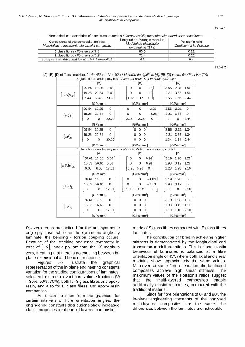
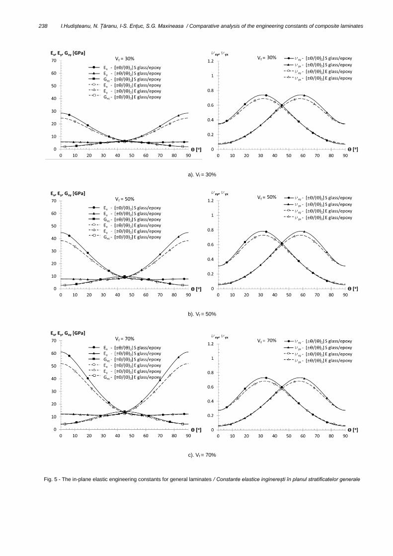
Figures 5-7 illustrate the graphical representation of the in-plane engineering constants variation for the studied configurations of laminates, selected for three relevant fibre volume fractions (Vf = 30%; 50%; 70%), both for S glass fibres and epoxy resin, and also for E glass fibres and epoxy resin composites.
As it can be seen from the graphics, for certain intervals of fibre orientation angles, the engineering constants distributions show increased elastic properties for the multi-layered composites
made of S glass fibres compared with E glass fibres laminates.
The contribution of fibres in achieving higher stiffness is demonstrated by the longitudinal and transverse moduli variations. The in-plane elastic behaviour of laminates is balanced at a fibre orientation angle of 45o, where both axial and shear modulus show approximately the same values. Moreover, at same fibre orientation, the laminated composites achieve high shear stiffness. The maximum values of the Poisson’s ratios suggest that the multi-layered composites enable additionally elastic responses, compared with the traditional material.
Since for fibre orientations of 0o and 90o, the in-plane engineering constants of the analysed multi-layered composites are the same, the differences between the laminates are noticeable
238 I.Hudișteanu, N. Țăranu, I-S. Ențuc, S.G. Maxineasa / Comparative analysis of the engineering constants of composite laminates
a). Vf = 30%
b). Vf = 50%
c). Vf = 70%
Fig. 5 - The in-plane elastic engineering constants for general laminates / Constante elastice inginerești în planul stratificatelor generale
I.Hudișteanu, N. Țăranu, I-S. Ențuc, S.G. Maxineasa / Analiza comparativă a constantelor elastice inginerești 239 ale stratificatelor compozite
a). Vf = 30%
b). Vf = 50%
c). Vf = 70%
Fig. 6 - The in-plane elastic engineering constants for anti-symmetric angle-ply laminates / Constante elastice inginerești în planul stratificatelor unghiulare antisimetrice.

240 I.Hudișteanu, N. Țăranu, I-S. Ențuc, S.G. Maxineasa / Comparative analysis of the engineering constants of composite laminates
a). Vf = 30%
b). Vf = 50%
c). Vf = 70%
Fig. 7 - The in-plane elastic engineering constants for symmetric angle-ply laminates / Constante elastice inginerești în planul stratificatelor unghiulare simetrice .

I.Hudișteanu, N. Țăranu, I-S. Ențuc, S.G. Maxineasa / Analiza comparativă a constantelor elastice inginerești 241 ale stratificatelor compozite
for certain intervals of fibre orientation angles. In case of the longitudinal modulus Ex, angle-ply laminates are stiffer than the general configuration laminate, for fibre orientation angles up to 5o to 40o, while for transverse
modulus Ey, for o8550 . Significant differences
occur in case of the shear modulus Gxy, for fibre orientations of 10o to 80o. For the Poisson’s ratio xy ,
the stiffening effect is visible for 15-50o fibre orientations interval and, as expected, in case of yx ,
for fibre orientation angles of 40o to 75o. As shown in Figures 5-7, the stiffness behaviour
of laminated composites is improved with increasing fibre volume fraction, but also through suitable choices of the stacking sequences. Therefore, the elastic performance of particular laminates compared with general laminates is demonstrated for the specified intervals of fibre orientations.
The symmetric laminates show superior elastic characteristics than the anti-symmetric or asymmetric multi-layered structures.
Therefore, the tailoring benefit of composite laminates to achieve the required stiffness properties in the desired direction, can be obtained by selecting the right influencing parameters, such as constituents of the composite, fibre volume fractions, fibre orientations, number of plies and stacking sequences.
4. Conclusions
A comparative analysis of the elastic engineering constants of three types of laminates has been performed. The influence of the elementary layers’ parameters on the elastic properties of composite laminates is demonstrated by graphical distributions of the in-plane engineering constants. The importance of using the appropriate fiber orientation angle and stacking sequence or the adequate composite material is crucial when it is necessary to meet the stiffness requirements for the design of a composite structure.
The variation curves illustrate improved elastic behaviour of particular laminates compared with general laminates, introduced by the stacking sequence symmetry. Interchanging this important parameter when designing multi-layered composites, will affect its response to bending or may influence the coupling effects. Symmetric laminates are therefore preferred for most practical situations.
In terms of material aspects, the laminated composites realized of S glass fibres reach the maximum values of the elastic engineering constants, for certain fibre orientations.
REFERENCES
1. B.D. Agarwal, L.J. Broutman, K. Chandrashekhara, Analysis and performance of fibre composites, Third Edition, Wiley Interscience, New York, 2006.
2. M.A. Masuelli, Fiber Reinforced Polymers – The Technology Applied for Concrete Repair, InTech Publisher, 2013.
3. V.V. Vasiliev, E. Morozov, Advanced Mechanics of Composite Materials and Structural Elements. Third Edition, Elsevier, 2013.
4. J.W.S. Hearle, High-performance fibres, CRC Press, Woodhead Publishing Ltd, 2001.
5. A.K. Kaw, Mechanics of Composite Materials. Second Edition, CRC Press, Taylor & Francis Group, New York, 2006.
6. M. Amăreanu, The confinement of concrete with fiber reinforced polymers - Method of consolidation of structural elements, Romanian Journal of Materials, 2014, 44(1), 25.
7. N. Țăranu, C. Banu, G. Oprișan, M. Budescu, V. Munteanu, O. Ioniță, Tensile characteristics of glass fibre reinforced polymeric bars, Romanian Journal of Materials, 2010, 40(4), 323.
8. C.O. Burada, C.M. Mirițoiu, M.M. Stănescu, D. Bolcu, The vibration behaviour of composite sandwich platbands reinforced with glass fiber, Romanian Journal of Materials, 2015, 45(3), 244.
9. C.O. Burada, C.M. Mirițoiu, D. Bolcu, M.M. Stănescu, Experimental determinations of the damping factor and stiffness for new sandwich platbands with different reinforcement and core, Romanian Journal of Materials, 2014, 44(4), 405.
10. M. Sonmez, D. Ficai, A. Ficai, L. Alexandrescu, G. Voicu, E. Andronescu, Functionalization of glass fibers for obtaining polypropylene based composite materials, Romanian Journal of Materials, 2014, 44(1), 88.
11. M. Dima, C. Frâncu, Method for testing glass fibre reinforced polymer composites (GFRP’s) with polyester matrix, Romanian Journal of Materials, 2014, 44(3), 304.
12. D. Flore, K. Wegener, Modelling the mean stress effect on fatigue life of fibre reinforced plastics, International Journal of Fatigue, 2016, 82, 689.
13. L.P. Borrego, J.D.M. Costa, J.A.M. Ferreira, H. Silva, Fatigue behaviour of glass fibre reinforced epoxy composites enhanced with nanoparticles, Composites: Part B, 2014, 62, 65.
14. D. Ratna, Handbook of Thermoset Resins, iSmithers Publisher, Shawbury, UK, 2009.
15. T.W. Chou, Microstructural design of fiber composites, Cambridge Univ. Press, New York, 2005.
16. L. Bejan, N. Taranu, A. Sarbu, Advanced polymeric
composites with hybrid reinforcement, Journal of Optoelectronics and Advanced Materials, 2010, 12 (9), 1930
17. G.H. Staab, Laminar Composites, Butterworth-Heinemann, Reed Elsevier Group, 1999.
18. I.M. Daniel, O. Ishai, Engineering Mechanics of Composite Materials. Second Edition, Oxford Univ. Press, Oxford, New York, 2006.
19. N. Ţăranu, L. Bejan, R. Cozmanciuc, R. Hohan, Elements of composite materials, Politehnium Publishing House, Iaşi, 2013.
20. N. Țăranu, D. Isopescu, Structures made of composite materials, Ed. Vesper, Iași, 1996.
21. E.J. Barbero, Introduction to Composite Materials Design. Second Edition, CRC Press, Taylor & Francis Group, New York, 2011.
22. M.H. Datoo, Mechanics of fibrous composites, Elsevier LTD, New York, 1991.
23. R.F. Gibson, Principles of Composite Material Mechanics, CRP Press, Taylor & Francis Group, Boca Raton, 2012.
24. C.T. Herakovich, Mechanics of Fibrous Composites, John Wiley & Sons, Inc., Univ. of Virginia, United States of America, 1998.
25. I. Dupir (Hudișteanu), N. Țăranu, The influence of the stacking sequence on stress and strain distributions for quasi-isotropic laminates, Bulletin of the Polytechnic Institute of Jassy, Construction. Architecture Section, 2015, LXI (LXV) (2), 97.
26. R.M. Jones, Mechanics of Composite Materials. Second Edition, Taylor & Francis, Inc., Philadelphia, 1999.
27. A.T. Nettles, Basic Mechanics of Laminated Composite Plates, NASA Reference Publication 1351, 1994.
****************************************************************************************************************************


![INTERPRETAREA COMPARATIVĂ A ETNICITĂŢII RURALE, … · românilor comlăuşeni şi a romilor [cf. Chelcea, Lăţea, 2000]; date privind familiile nobiliare maghiare de la Zăbala,](https://img.pdfslide.us/doc/110x75/5e34133ee7e6461e9808a254/interpretarea-comparativ-a-etnicitii-rurale-romnilor-comlfueni-i-a.jpg)