Embed Size (px)
Citation preview
AN990: BLUETOOTH SERIAL PORT PROFILE
iWRAP APPLICATION NOTE
Thursday, 19 April 2012
Version 1.2

Silicon Labs
VERSION HISTORY
Version Comment
1.0 First version
1.1 Advanced usage tips and mode switching chapters added
1.2 Multiplexing mode documentation added

Silicon Labs
Contents 1 Introduction ..................................................................................................................................................... 5
1.1 Serial Port Profile ...................................................................................................................................... 5
2 iWRAP firmware overview ............................................................................................................................... 6
3 Using SPP with iWRAP ................................................................................................................................... 8
3.1 Configuration ............................................................................................................................................. 8
3.2 Service discovery ...................................................................................................................................... 9
3.3 Connection establishment ....................................................................................................................... 10 3.3.1 SPP data channel ........................................................................................................................... 10
3.3.2 Mode switching ............................................................................................................................... 10
3.4 Connection termination ............................................................................................................................. 11
3.4.1 SPP data channel ............................................................................................................................... 11
3.5 Advanced SPP information ..................................................................................................................... 12
3.5.1 Modem Control Signals (MSC) ....................................................................................................... 12 3.5.2 Maximum Transfer Unit (MTU) ....................................................................................................... 12
3.5.3 Bluetooth page mode ..................................................................................................................... 13
3.5.4 Carrier Detect (CD) signal .............................................................................................................. 13
3.5.5 Automatic connection establishment .............................................................................................. 13
3.5.6 Throughput optimization ................................................................................................................. 13 3.5.7 Latency optimization ....................................................................................................................... 13
3.5.8 Power saving .................................................................................................................................. 13
4 Multiplexing ................................................................................................................................................... 14
5 Example connection diagram ........................................................................................................................ 17
6 References ................................................................................................................................................... 18
Silicon Labs Page 5 of 19
1 Introduction This application note discusses Serial Port Profile (SPP) and its advantages and how it can be used. Also practical examples are given how the SPP is used with the iWRAP firmware.
1.1 Serial Port Profile
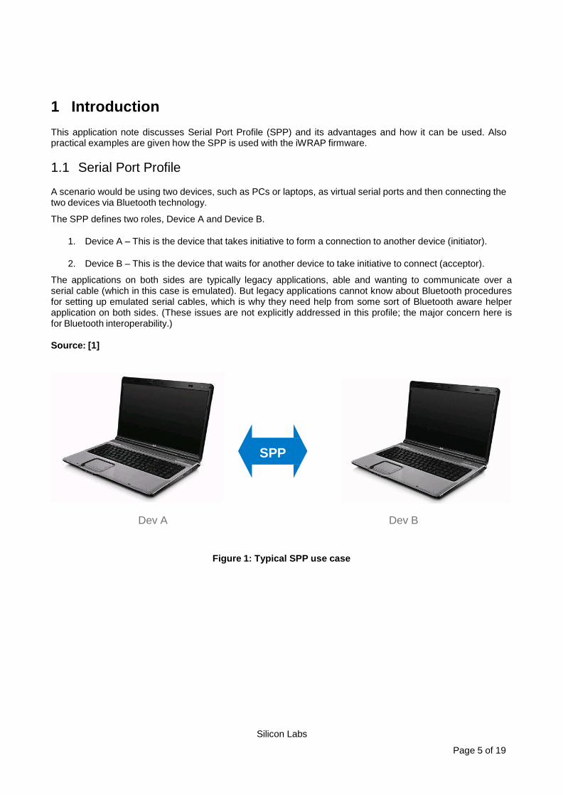
A scenario would be using two devices, such as PCs or laptops, as virtual serial ports and then connecting the two devices via Bluetooth technology.
The SPP defines two roles, Device A and Device B.
1. Device A – This is the device that takes initiative to form a connection to another device (initiator).
2. Device B – This is the device that waits for another device to take initiative to connect (acceptor).
The applications on both sides are typically legacy applications, able and wanting to communicate over a serial cable (which in this case is emulated). But legacy applications cannot know about Bluetooth procedures for setting up emulated serial cables, which is why they need help from some sort of Bluetooth aware helper application on both sides. (These issues are not explicitly addressed in this profile; the major concern here is for Bluetooth interoperability.)
Source: [1]
Dev A Dev B
Figure 1: Typical SPP use case
SPP

Silicon Labs Page 6 of 19
iWRAP
iWRAP
RFCOMM
SDP Audio
L2CAP / eL2CAP
Host Controller Interface
GPIO / AIO Link Manager
Host + application
PCM / I2S / SPDIF Baseband
Analogue Radio
2 iWRAP firmware overview iWRAP is an embedded firmware running entirely on the RISC processor of WT12, WT11, WT41 and WT32 modules. It implements the full Bluetooth protocol stack and serveral Bluetooth profiles. All software layers, including application software, run on the internal RISC processor in a protected user software execution environment known as a Virtual Machine (VM).
The host system can interface to iWRAP firmware through one or more physical interfaces, which are also shown in the figure below. The most common interfacing is done through the UART interface by using the ASCII commands that iWRAP firmware supports. With these ASCII commands, the host can access Bluetooth functionality without paying any attention to the complexity, which lies in the Bluetooth protocol stack. GPIO interface can be used for event monitoring and command execution. PCM, SPDIF, I2S or analog interfaces are available for audio. The available interfaces depend on the used hardware.
The user can write application code to the host processor to control iWRAP firmware using ASCII commands or GPIO events. In this way, it is easy to develop Bluetooth enabled applications.
On WT32 there is an extra DSP processor available for data/audio processing.
Hardware
Figure 2: iWRAP Bluetooth stack
UART / USB

Silicon Labs Page 7 of 19
In the figure above, a Bluegiga Bluetooth module with iWRAP firmware could be connected to a host system for example through the UART interface. The options are:
• If the host system has a processor, software can be used to control iWRAP by using ASCII based commands or GPIO events.
• If there is no need to control iWRAP, or the host system does not need a processor, iWRAP can be configured to be totally transparent and autonomous, in which case it only accepts connections or automatically opens them.
• GPIO lines that WRAP THOR modules offer can also be used together with iWRAP to achieve additional functionality, such as Carrier Detect or DTR signaling.
• Audio interfaces can be used to transmit audio over a Bluetooth link.

Silicon Labs Page 8 of 19
3 Using SPP with iWRAP This chapter instructs the SPP usage and configuration with the iWRAP firmware.
3.1 Configuration
SPP is enabled with command “SET PROFILE SPP {service_name}”
service_name This parameter configures a user friendly description of the service. Neither special characters nor white spaces are allowed. Service name ON enables the profile with the default name.
Finally a reset is needed to for the SPP profile to become active.
Below is an example how to enable SPP mode.
In iWRAP firmware SPP profile is enabled by default.
If no parameter is given, the profile will be disabled.
SET PROFILE SPP ON RESET
Silicon Labs Page 9 of 19
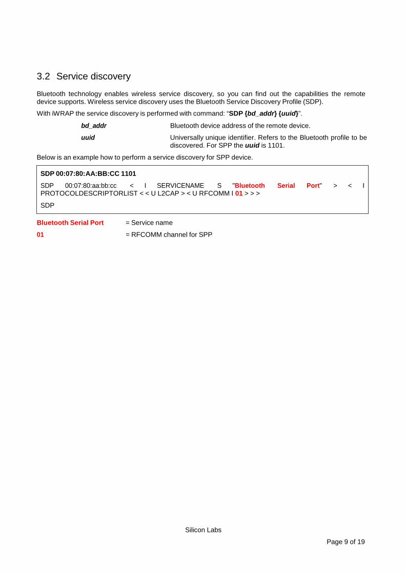
3.2 Service discovery
Bluetooth technology enables wireless service discovery, so you can find out the capabilities the remote device supports. Wireless service discovery uses the Bluetooth Service Discovery Profile (SDP).
With iWRAP the service discovery is performed with command: “SDP {bd_addr} {uuid}”.
bd_addr Bluetooth device address of the remote device.
uuid Universally unique identifier. Refers to the Bluetooth profile to be discovered. For SPP the uuid is 1101.
Below is an example how to perform a service discovery for SPP device.
Bluetooth Serial Port = Service name
01 = RFCOMM channel for SPP
SDP 00:07:80:AA:BB:CC 1101
SDP 00:07:80:aa:bb:cc < I SERVICENAME S "Bluetooth Serial Port" > < I PROTOCOLDESCRIPTORLIST < < U L2CAP > < U RFCOMM I 01 > > >
SDP
Silicon Labs Page 10 of 19
3.3 Connection establishment
3.3.1 SPP data channel
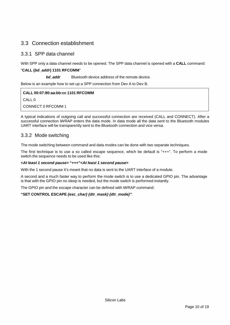
With SPP only a data channel needs to be opened. The SPP data channel is opened with a CALL command:
“CALL {bd_addr} 1101 RFCOMM”
bd_addr Bluetooth device address of the remote device.
Below is an example how to set up a SPP connection from Dev A to Dev B.
A typical indications of outgoing call and successful connection are received (CALL and CONNECT). After a successful connection iWRAP enters the data mode. In data mode all the data sent to the Bluetooth modules UART interface will be transparently sent to the Bluetooth connection and vice versa.
3.3.2 Mode switching
The mode switching between command and data modes can be done with two separate techniques.
The first technique is to use a so called escape sequence, which be default is “+++”. To perform a mode switch the sequence needs to be used like this:
<At least 1 second pause> “+++”<At least 1 second pause>
With the 1 second pause it’s meant that no data is sent to the UART interface of a module.
A second and a much faster way to perform the mode switch is to use a dedicated GPIO pin. The advantage is that with the GPIO pin no sleep is needed, but the mode switch is performed instantly.
The GPIO pin and the escape character can be defined with iWRAP command:
“SET CONTROL ESCAPE {esc_char} {dtr_mask} {dtr_mode}”.
CALL 00:07:80:aa:bb:cc 1101 RFCOMM
CALL 0
CONNECT 0 RFCOMM 1
Silicon Labs Page 11 of 19
3.4 Connection termination
3.4.1 SPP data channel
The SPP data channel can simply be closed with iWRAP command “CLOSE {link_id}”.
link_id Numeric connection identifier of the SPP associated RFCOMM link
SPP control channel termination.
CLOSE 0
NO CARRIER 0 ERROR 0
Silicon Labs Page 12 of 19
3.5 Advanced SPP information
This chapter contains advanced information and tips about the SPP usage with iWRAP. The exact descriptions of the commands used in this chapter can be found from the iWRAP user guide.
3.5.1 Modem Control Signals (MSC)
With iWRAP firmware, it is possible to transmit all the UART modem signals over the SPP (Serial Port Profile). The signals, which are: DSR, DTR, RTS, CTS, RI and DCD can be specified to GPIO pins on the Bluetooth modules allowing the status of the MSC signals to be reported over a Bluetooth link.
iWRAP allows several ways to monitor and change the status of MSC signals. Probably the most straightforward way is to bind the MSC signals to the physical GPIO pins. This can be done with the following iWRAP command:
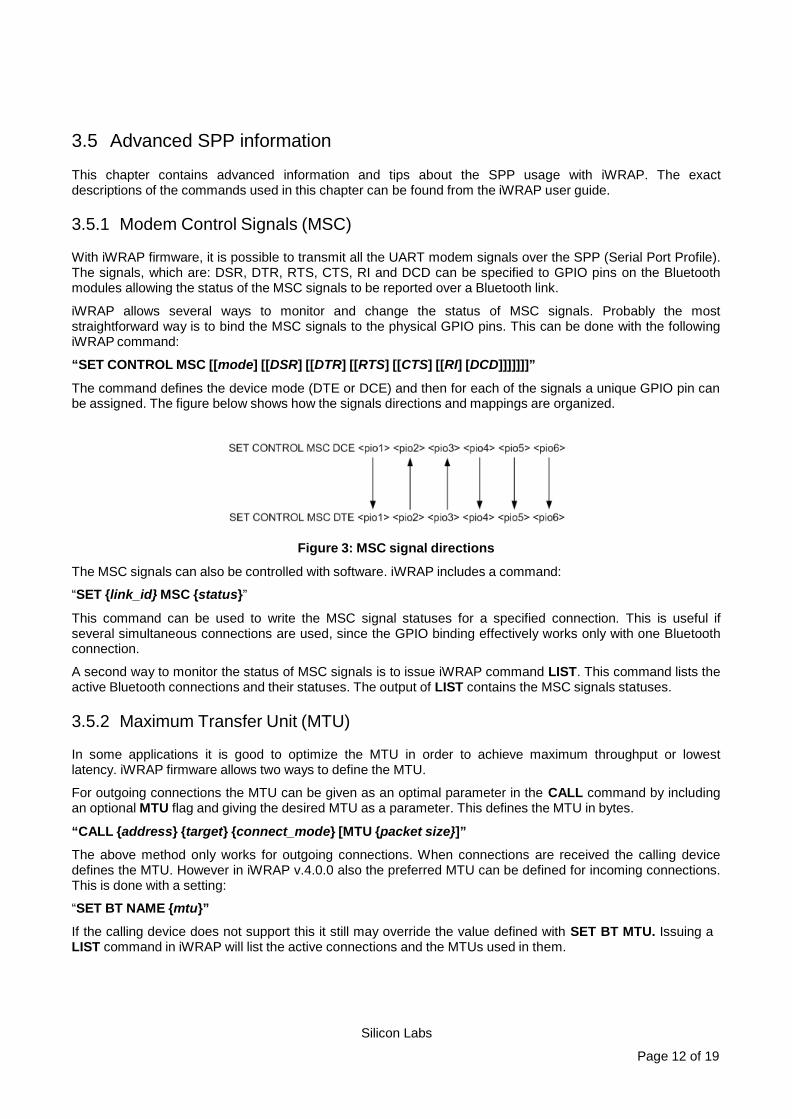
“SET CONTROL MSC [[mode] [[DSR] [[DTR] [[RTS] [[CTS] [[RI] [DCD]]]]]]]”
The command defines the device mode (DTE or DCE) and then for each of the signals a unique GPIO pin can be assigned. The figure below shows how the signals directions and mappings are organized.
Figure 3: MSC signal directions
The MSC signals can also be controlled with software. iWRAP includes a command:
“SET {link_id} MSC {status}”
This command can be used to write the MSC signal statuses for a specified connection. This is useful if several simultaneous connections are used, since the GPIO binding effectively works only with one Bluetooth connection.
A second way to monitor the status of MSC signals is to issue iWRAP command LIST. This command lists the active Bluetooth connections and their statuses. The output of LIST contains the MSC signals statuses.
3.5.2 Maximum Transfer Unit (MTU)
In some applications it is good to optimize the MTU in order to achieve maximum throughput or lowest latency. iWRAP firmware allows two ways to define the MTU.
For outgoing connections the MTU can be given as an optimal parameter in the CALL command by including an optional MTU flag and giving the desired MTU as a parameter. This defines the MTU in bytes.
“CALL {address} {target} {connect_mode} [MTU {packet size}]”
The above method only works for outgoing connections. When connections are received the calling device defines the MTU. However in iWRAP v.4.0.0 also the preferred MTU can be defined for incoming connections. This is done with a setting:
“SET BT NAME {mtu}”
If the calling device does not support this it still may override the value defined with SET BT MTU. Issuing a LIST command in iWRAP will list the active connections and the MTUs used in them.
Silicon Labs Page 13 of 19
3.5.3 Bluetooth page mode
The visibility and connect ability of a Bluetooth device can be controlled. Usually a device should not be visible or connectable unless needed by the application. In iWRAP the following command can be used to control these modes:
“SET BT PAGEMODE {page_mode} {page_timeout} {page_scan_mode}” 3.5.4 Carrier Detect (CD) signal
A GPIO pin can be used to indicate an active Bluetooth connection. In iWRAP this feature can be enabled with command:
“SET CONTROL CD {cd_mask} {datamode}” 3.5.5 Automatic connection establishment
An automatic connection establishment mode can be also used with iWRAP. In this mode iWRAP tries to automatically establish a connection to a paired Bluetooth device. This feature can be enabled or disabled with the following iWRAP command:
“SET CONTROL AUTOCALL {target} {timeout} {profile}” 3.5.6 Throughput optimization
The basic tricks for optimizing iWRAP throughput are listed below:
• Data transmission from master to slave is slightly faster then vice versa.
• Best throughput has been achieved with MTU size 667, which is the default value in iWRAP.
• The MTU should be optimized so that it matches the packet size used by the application level protocol. This optimizes the efficiency.
• The UART baud rate should always be higher then the desired throughput. 3.5.7 Latency optimization
The basic tricks for optimizing iWRAP latency are listed below:
• Data transmission from master to slave is slightly quicker then vice versa
• The MTU should be optimized so that it matches the packet size used by the application level protocol. This optimizes the efficiency and also latency.
• Sniff power saving mode can be used to reduce the latency. The lowest latency can be achieved by using the smallest possible sniff intervals, which can be taken in to use for example with command: ”SET BT SNIFF 4 2”. This however slightly increases the current consumption.
3.5.8 Power saving
iWRAP offers two power saving options. Sniff mode, which can be used to save power for active Bluetooth connections and deep sleep more which puts the internal processor into a reduced duty cycle mode. Please refer to iWRAP user guide for more information about sniff and deep sleep modes.
One should also know that when Bluetooth connections are in active mode i.e. no power saving in use the master device uses 3-4 times less power then a slave device. Therefore for battery powered applications it might be useful to configure the device as a master rather then a slave, eventually considering role switching.

Silicon Labs Page 14 of 19
4 Multiplexing In the typical operational mode iWRAP has separate command and data modes. In command mode iWRAP commands can be issued and in data mode data transmission with other Bluetooth devices can take place. However the limitation of this mode is that data can be sent or received from one device at a time and a time consuming mode switching needs to be performed to switch to an other connection.
iWRAP however includes an other operational mode called multiplexing mode also referred as MUX mode. In the multiplexing mode no separate command and data modes exists but all the transactions occur in a single mode. However a special MUX protocol needs to be used for iWRAP commands and data, since they need to be sent over a single UART interface.
This chapter explains the basics of the multiplexing mode.
The multiplexing mode is enabled or disabled with iWRAP command:
“SET CONTROL MUX {mode}”
An example how to enabled MUX mode:
An example how to disable multiplexing mode
The command used above is “SET CONTROL MUX 0” in the frame format used by MUX mode. The command must be sent in hex format, NOT in ASCII format.
BF FF 00 11 53 45 54 20 43 4f 4e 54 52 4f 4c 20 4d 55 58 20 30 00
READY
SET CONTROL MUX 1
¿READY.

Silicon Labs Page 15 of 19
The multiplexing frame format is presented below:
Length: Name: Description: Value:
8 bits SOF Start of frame 0xBF
8 bits
LINK
Bluetooth connection ID (link_id)
0x00 - 0x06 or
0xFF (iWRAP control)
6 bits FLAGS Frame flags always 0x00
10 bits LENGTH Size of data field in bytes -
0-1023 Bytes DATA Application data or iWRAP cmd. -
8 bits nLINK {LINK} XOR 0xFF -
Table 1: Multiplexing frame format
When multiplexing mode is enabled, all the commands and data sent from host to iWRAP must be sent by using the frame format described above instead of plain ASCII commands. Also, the responses and data coming from iWRAP to the host are sent using the same format. iWRAP firmware autonomously processes the frames and decides whether they contain iWRAP control commands or data which should be forwarded to a Bluetooth connection.
The next figure illustrates the host-iWRAP-host communications in multiplexing mode.
Figure 4: AT-OK test using MUX mode
Silicon Labs Page 16 of 19
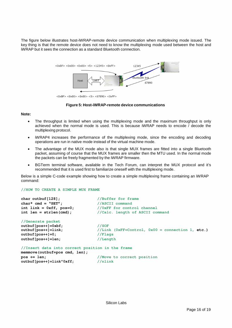
The figure below illustrates host-iWRAP-remote device communication when multiplexing mode issued. The key thing is that the remote device does not need to know the multiplexing mode used between the host and iWRAP but it sees the connection as a standard Bluetooth connection.
Figure 5: Host-iWRAP-remote device communications
Note:
• The throughput is limited when using the multiplexing mode and the maximum throughput is only achieved when the normal mode is used. This is because iWRAP needs to encode / decode the multiplexing protocol.
• iWRAP4 increases the performance of the multiplexing mode, since the encoding and decoding operations are run in native mode instead of the virtual machine mode.
• The advantage of the MUX mode also is that single MUX frames are fitted into a single Bluetooth packet, assuming of course that the MUX frames are smaller then the MTU used. In the normal mode the packets can be freely fragmented by the iWRAP firmware.
• BGTerm terminal software, available in the Tech Forum, can interpret the MUX protocol and it’s recommended that it is used first to familiarize oneself with the multiplexing mode.
Below is a simple C-code example showing how to create a simple multiplexing frame containing an iWRAP command:
//HOW TO CREATE A SIMPLE MUX FRAME char outbuf[128]; //Buffer for frame char* cmd = “SET”; //ASCII command int link = 0xff, pos=0; //0xFF for control channel int len = strlen(cmd); //Calc. length of ASCII command //Generate packet outbuf[pos++]=0xbf; //SOF outbuf[pos++]=link; //Link (0xFF=Control, 0x00 = connection 1, etc.) outbuf[pos++]=0; //Flags outbuf[pos++]=len; //Length //Insert data into correct position in the frame memmove(outbuf+pos cmd, len); pos += len; //Move to correct position outbuf[pos++]=link^0xff; //nlink
Silicon Labs Page 17 of 19
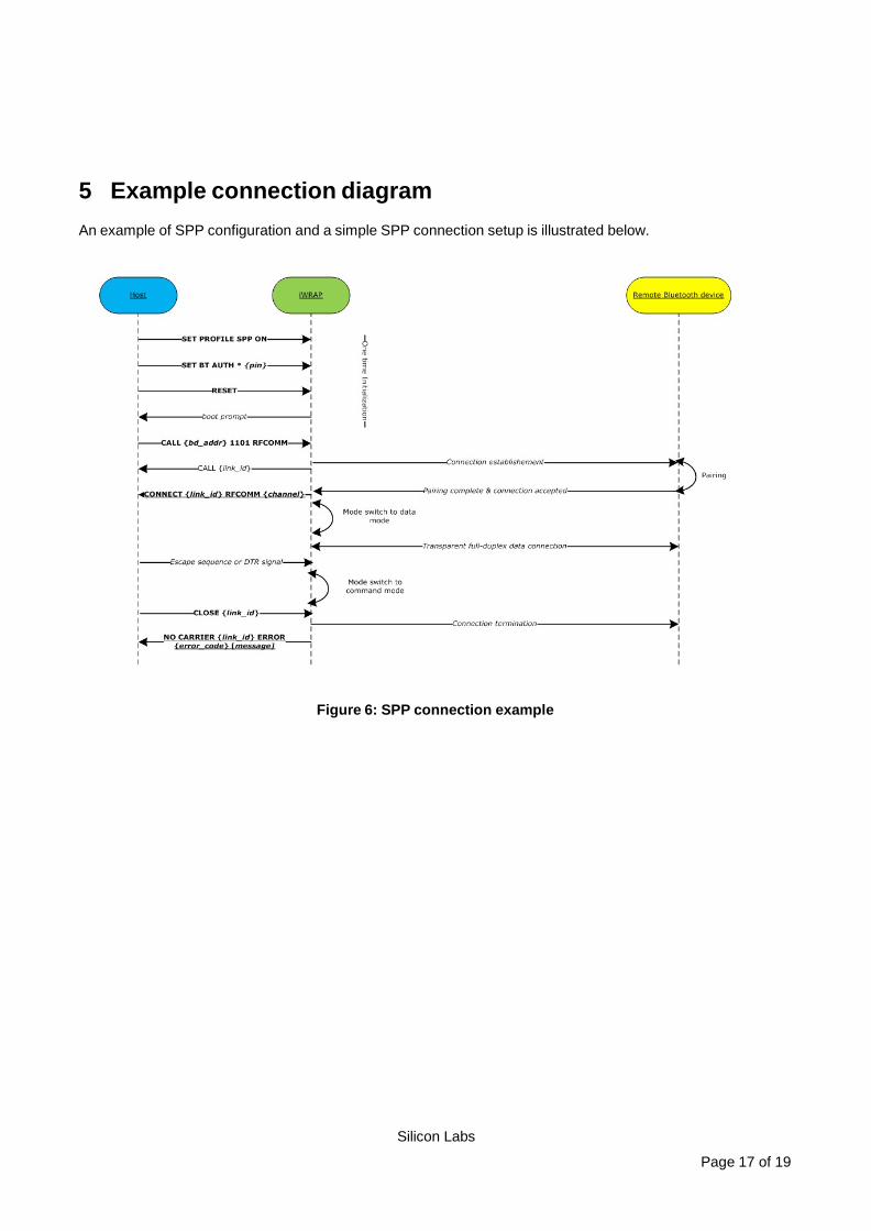
5 Example connection diagram An example of SPP configuration and a simple SPP connection setup is illustrated below.
Figure 6: SPP connection example

Silicon Labs Page 18 of 19
6 References [1] The Bluetooth SIG, Serial Port Profile overview, URL:
http://www.bluetooth.com/Bluetooth/Technology/Works/SPP.htm

http://www.silabs.com
Silicon Laboratories Inc.400 West Cesar ChavezAustin, TX 78701USA
Simplicity StudioOne-click access to MCU and wireless tools, documentation, software, source code libraries & more. Available for Windows, Mac and Linux!
IoT Portfoliowww.silabs.com/IoT
SW/HWwww.silabs.com/simplicity
Qualitywww.silabs.com/quality
Support and Communitycommunity.silabs.com
DisclaimerSilicon Laboratories intends to provide customers with the latest, accurate, and in-depth documentation of all peripherals and modules available for system and software implementers using or intending to use the Silicon Laboratories products. Characterization data, available modules and peripherals, memory sizes and memory addresses refer to each specific device, and "Typical" parameters provided can and do vary in different applications. Application examples described herein are for illustrative purposes only. Silicon Laboratories reserves the right to make changes without further notice and limitation to product information, specifications, and descriptions herein, and does not give warranties as to the accuracy or completeness of the included information. Silicon Laboratories shall have no liability for the consequences of use of the information supplied herein. This document does not imply or express copyright licenses granted hereunder to design or fabricate any integrated circuits. The products are not designed or authorized to be used within any Life Support System without the specific written consent of Silicon Laboratories. A "Life Support System" is any product or system intended to support or sustain life and/or health, which, if it fails, can be reasonably expected to result in significant personal injury or death. Silicon Laboratories products are not designed or authorized for military applications. Silicon Laboratories products shall under no circumstances be used in weapons of mass destruction including (but not limited to) nuclear, biological or chemical weapons, or missiles capable of delivering such weapons.
Trademark InformationSilicon Laboratories Inc.® , Silicon Laboratories®, Silicon Labs®, SiLabs® and the Silicon Labs logo®, Bluegiga®, Bluegiga Logo®, Clockbuilder®, CMEMS®, DSPLL®, EFM®, EFM32®, EFR, Ember®, Energy Micro, Energy Micro logo and combinations thereof, "the world’s most energy friendly microcontrollers", Ember®, EZLink®, EZRadio®, EZRadioPRO®, Gecko®, ISOmodem®, Precision32®, ProSLIC®, Simplicity Studio®, SiPHY®, Telegesis, the Telegesis Logo®, USBXpress® and others are trademarks or registered trademarks of Silicon Laborato-ries Inc. ARM, CORTEX, Cortex-M3 and THUMB are trademarks or registered trademarks of ARM Holdings. Keil is a registered trademark of ARM Limited. All other products or brand names mentioned herein are trademarks of their respective holders.