Embed Size (px)
Citation preview

AN805: Si446x Wireless MBUS Receiver
This application note describes how to create a wireless MBUS-compliant device usingSilicon Labs Si4461/63/64 cost-efficient, high-performance EZRadioPRO® RF trans-ceiver and EZR32 wireless MCU family. It does not cover the duty cycle and other tim-ing requirements of the standard; rather, it focuses on the RF-related requirements ofthe prEN 13757-4 rev:2013 wireless MBUS standard, unless noted otherwise. The RFmeasurements listed in this application note were performed on the 4461-868-PDK de-velopment kit using the Wireless Development Suite. Refer to 2.6 Radio Link Require-ments for Mode F for more details.
KEY POINTS
• Silicon Labs Si446x high-performance RFtransceivers support all the WMBUSmodes, including S, T, R, C, F and variousN modes
• The EZRadioPRO® transceivers meetWMBUS specifications
silabs.com | Smart. Connected. Energy-friendly. Rev. 0.3

1. Summary
Table 1.1 Measured Sensitivity for 80% PER on page 1 summarizes the measured sensitivity for 80% PER and indicates that theradio meets the given MBUS mode specification.
Table 1.1. Measured Sensitivity for 80% PER
Mode Parameter Measurement Results Comment
1 S1,S2 Sensitivity –110 dBm Meets MBUS Specifica-tions
freq. offset, data rate, |deviation corners
Meets all Corners
2 T1, T2 Sensitivity –106 dBm Meets MBUS Specifica-tions
freq. offset, data rate, de-viation corners
Meets all Corners
3 R2 Sensitivity –117 dBm Meets MBUS Specifica-tions
freq. offset, data rate, de-viation corners
Meets all Corners
4 C Sensitivity –110 dBm
(Meter to other)
-113 dBm
(Other to meter)
Meets MBUS Specifica-tions
freq. offset, data rate, de-viation corners
Meets All Corners
5 N(1,2)a/b/e/f Sensitivity –122 dBm Meets MBUS Specifica-tions1 , 2
freq. offset, data rate, de-viation corners
Meets All Corners
6 N(1,2)c/d Sensitivity –120.5 dBm Meets MBUS Specifica-tions2
freq. offset, data rate, de-viation corners
Meets all Corners
7 Sensitivity –113 dBm Meets MBUS Specifica-tions
N2g freq. offset, data rate, de-viation corners
Meets all corners
8 F Sensitivity –117 dBm Meets MBUS Specifica-tions
freq. offset, data rate, de-viation corners
Meets all corners withlonger wake-up window
Note:1. 2.4 kHz deviation is used for the measurement according to the prEN 13757-4:2013 draft version of the standard.2. The deviation offset tolerances were measured according to the prEN 13757-4:2013 draft version of the standard.
AN805: Si446x Wireless MBUS ReceiverSummary
silabs.com | Smart. Connected. Energy-friendly. Rev. 0.3 | 1

2. Wireless MBUS Standard
The Wireless MBUS standard (EN 13757-4) specifies two kinds of devices: “Meters” and “Others” (mobile readout devices, data collec-tors, etc.). The standard also defines several types of communication between devices:• Mode S ("Stationary mode"):
• Mode S1: unidirectional link from the Meter to the Other device• Mode S1m: unidirectional link from the Meter to the Other device• Mode S2: bidirectional communication between the Meter and Other device
• Mode T ("Frequent transmit mode"):• Mode T1: unidirectional link from the Meter to the Other device• Mode T2: bidirectional link from the Meter to the Other device
• Mode R ("Frequent receive mode"): special, multipchannel receiving mode• Mode R2: bidirectional link from Meter to Other device
• Mode C ("Compact Mode"):• Mode C1: unidirectional link from the Meter to the Other device• Mode C2: bidirectional link from the Meter to the Other device
• Mode N ("Narrowband VHF Mode"):• Mode N1a-g: unidirectional link from the Meter to the Other device• Mode N2a-g: bidirectional link from the Meter to the Other device
• Mode F: protocol using routers
The following tables list the radio requirements for the transmitter and receiver for Mode S, T, R, C, N, and F devices.
AN805: Si446x Wireless MBUS ReceiverWireless MBUS Standard
silabs.com | Smart. Connected. Energy-friendly. Rev. 0.3 | 2

2.1 Radio Link Requirements for Mode S
Table 2.1. Transmitter Requirements for Mode S
Characteristic Mode Sym Min Typ Max Unit Note
Center Fre-quency
(Transmit OnlyMeter, S1-Sub-Mode)
868.25 868.30 868.35 MHz ~ 60 x 10 – 6
(ppm)
Center Fre-quency
(Other and S2-Mode)
868.278 868.300 868.322 MHz ~ 25 x 10 – 6
(ppm)
FSK Deviation ±40 ±50 ±80 kHz
Chip RateTransmit
fchip — 32.768 — kcps
Chip Rate Tol-erance
— — ±1.5 %
Digital Bit Jit-ter1
— — ±3 µs
Data Rate(Manchester)2
— fchip × 1/2 — bps
PreambleLength Includ-ing Bit/ ByteSync,
Both Directions
S2,
S1-M48
— —
chips
PreambleLength Includ-ing Bit/byteSync
S1 PL 576— —
chipsOptional for S2
Postamble(Trailer)Length3
2 — 8 chips
Response De-lay4
(Other To Me-ter Communi-cation)
tRO 3 — 50 ms
FAC Transmis-sion Delay5 , 6
S2 tTxD N × 1000 – 0.5 N × 1000 N × 1000 + 0.5 ms N = 2,3,4,or 5
FAC Time Out7 S2 tTO 25 — 30 s
AN805: Si446x Wireless MBUS ReceiverWireless MBUS Standard
silabs.com | Smart. Connected. Energy-friendly. Rev. 0.3 | 3

Characteristic Mode Sym Min Typ Max Unit Note
Note:1. The bit jitter shall be measured at the output of the microcontroller or encoder circuit.2. Each bit shall be coded as two chips (Manchester encoding).3. The postamble (trailer) shall consist of n = 1 to 4 “ones”, i.e., the chip sequence is n x (01).4. Response delay: After transmitting a frame in S2-mode, the receiver shall be ready for the reception of a response in a time
shorter than the minimum response delay and shall be receiving at least for the duration of the maximum response delay.5. FAC Transmission delay describes the time by which a meter shall delay the first response to a received message from another
device referred to in its last transmission. This delay shall also be applied between the first response of the meter and the nextrepeated response of the meter and all following repeated responses during the Frequent Access Cycle (FAC). The referencetime point shall be the end of preamble (end of sync sequence) of the meter transmission. For timing diagrams, see Appendix E.
6. The selected timeslot, N, shall be the same throughout the Frequent Access Cycle.7. FAC Time out: is the time period between the last successful reception of a frame from the Other Device during the Frequent
Access Cycle (FAC) and the moment where the repetition of the last response of the Meter shall be stopped (end of FrequentAccess Cycle).
Table 2.2. Receiver Requirements for Mode S
Characteristic Class Sym Min Typ Max Unit
Sensitivity (BER< 102) or (PER <0.8)1
HR Po –100 –105 — dBm
Blocking Per-formance2
LR 3 — — Category
Blocking Per-formance2, 3
MR 2 — — Category
Blocking Per-formance23, 4
HR 2 — — Category
Acceptable ChipRate Tolerance
Dfchip — — ± 2 %
Chip rate (Meter) fchip — 32,768 — kcps
Note:1. At a frame size of 20 bytes.2. Receiver category according to ETSI En 300 220-1, V2, 4, 1:2012, 4.1.1.3. Additional requirement for class MR and class HR receivers: The equipment shall meet the immunity requirements as specified in
ETSI EN 301 489-1, V1.9.2: 2011, 9.2.4. Additional requiremen for class HR receivers: Adjacent band selectivity shall be 40 dB when measured according to ETSI EN 300
220-1, v2.4.1: 2012, 8.3.
AN805: Si446x Wireless MBUS ReceiverWireless MBUS Standard
silabs.com | Smart. Connected. Energy-friendly. Rev. 0.3 | 4

2.2 Radio Link Requirements for Mode T
Table 2.3. Transmitter Requirements for Mode T
Characteristic Mode Sym Min Typ Max Unit Note
Center Fre-quency (Meterto Other)
T1,T2 868.90 868.95 869.00 MHz ~ 60 x 10 – 6
(ppm)
Center Fre-quency (Otherto Meter)
T2 868.278 868.300 868.322 MHz ~ 25 x 10 – 6
(ppm)
FSK Deviation(Meter to Oth-er)
T1,T2 ±40 ±50 ±80 kHz
FSK Deviation(Other to Me-ter)
T2 ±40 ±50 ±80 kHz
Chip RateTransmit (Me-ter to Other)
T1,T2 fchip 90 100 110 kcps
Rate Variationwithin Header+ Frame (Me-ter)
T1,T2 Dfchip — 0 ±1 %
Data Rate1
(Meter to Oth-er, 3 out of 6Encoding)
T1,T2 — fchip × 2/3 — bps
Chip RateTransmit (Oth-er to Meter)
T2 — 32.768 — kcps
Chip Rate Tol-erance
(Other to Me-ter)
T2 — — ±1.5 %
Digital Bit Jit-ter1
T2 — — ±3 us
Data Rate
(Other to Me-ter, Manches-ter)2
T2 — fchip × 1/2 — bps
PreambleLength Includ-ing Bit / ByteSync
Both Directions
T1,T2 PL 48 — — chips
Postamble(Trailer)Length3
T1,T2 2 — 8 chips
AN805: Si446x Wireless MBUS ReceiverWireless MBUS Standard
silabs.com | Smart. Connected. Energy-friendly. Rev. 0.3 | 5

Characteristic Mode Sym Min Typ Max Unit Note
Response De-lay4
(Other to MeterCommunica-tion)
T2 tRO 2 — 3 ms
FAC Transmis-sion Delay 5 , 6
T2 tTxD N×1000 – 0.5 N×1000 N×1000 + 0.5 ms N = 2,3,4, or 5
FAC Time Out7 T2 tTO 25 — 30 s
Note:1. Each nibble (4 bits) shall be coded as six chips.2. The bit jitter shall be measured at the output of the microprocessor or encoder circuit.3. The postamble (trailer) shall consist of at least of at least two alternating chips. If the last chip of the CRC was a zero, then the
minimum postamble shall be “10”; otherwise, it shall be “01”.4. Response delay: after transmitting a frame including the postamble, the receiver shall be ready for the reception of a response in
a time shorter that the minimum response delay. After transmitting a frame, the receiver shall listen for a possible response for atleast the maximum response delay.
5. FAC Transmission delay describes the time by which a meter shall delay the first response to a received message from anotherreceived message from another device referred to in its last transmission. This delay shall also be applied between the first re-sponse of the meter and the next repeated response of the meter and all following repeated responses during the Frequent Ac-cess Cycle (FAC). The reference time point shall be the end of preamble (end of sync sequence) of the meter transmission.
6. The selected timeslot, N, shall be the same throughout the Frequent Access Cycle.7. FAC Time out is the time period between the last successful reception of a frame from the other device during the Frequent Ac-
cess Cycle (FAC) and the moment when the repetition of the last response of the meter shall be stopped (end of Frequent Ac-cess Cycle).
Table 2.4. Receiver Requirements for Mode T
Characteristic Class Sym Min Typ Max Unit Note
Sensitivity(BER < 10–2)or (PER <0,8)1
HR Po –100 –105 — dBm
Blocking Per-formance2
LR — 3 — Category
Blocking Per-formance 2, 3
MR — 2 — Category
Blocking Per-formance 23, 4
HR — 2 — Category
AcceptableHeader ChipRate Range:(Other)
T1,T2 fchip 88 100 112 kcps ~± 12%
AcceptableChip Rate Var-iation DuringHeader andFrame: (Other)
T1,T2 Dfchip — 0 ±2 %
AcceptableChip Rate Tol-erance
T2 Dfchip — ±2 %
AN805: Si446x Wireless MBUS ReceiverWireless MBUS Standard
silabs.com | Smart. Connected. Energy-friendly. Rev. 0.3 | 6

Characteristic Class Sym Min Typ Max Unit Note
Chip Rate(Meter)
T2 fchip — 32,768 — kcps
Acceptablechip rate toler-ance (meter)
T2 Dfchip2 — 0 ±2 % —
Note:1. At a frame size of 20 bytes.2. Receiver category according to ETSI EN 300 220-1, V2.4.1:2012, 4.1.1.3. Additional requirement for class MR and class HR receivers: The equipment shall meet the immunity requirements as specified in
ETSI EN 301 489-1, V1.9.2: 2011, 9.2.4. Additional requirement for class HR receivers: Adjacent band selectivity shall be \>40 dB when measured according to ETSI EN
300 220-1, V2.4.1: 2012, 8.3.
AN805: Si446x Wireless MBUS ReceiverWireless MBUS Standard
silabs.com | Smart. Connected. Energy-friendly. Rev. 0.3 | 7

2.3 Radio Link Requirements for Mode R2
Table 2.5. Transmitter Requirements for Mode R2
Characteristic Mode Sym Min Typ Max Unit Note
Center Fre-quency (Other)
— 868.33 — MHz
Center Fre-quency (Meter)
— 868.030 + n x0.06
— MHz
Frequency Tol-erance (Meter/Other)
— 0 ±17 ~ 20 x 10 – 6(ppm)
FSK Deviation ±4.8 ±6 ±7.2 kHz
Chip Rate(Wakeup andCommunica-tions)
fchip — 4.8 kcps
Chip rate Tol-erance
(Wakeup andCommunica-tions
— — ±1.5 %
Digital Bit Jit-ter1
— — ±15 us
Data rate(Manchester)2
— fchip × 1/2 — bps
PreambleLength Includ-ing Bit / ByteSync
PL 96 — — chips
Postamble(Trailer)Length3
2 — 8 chips
Response De-lay4 (Other toMeter Commu-nication)
tRO 3 — 50 ms
Response De-lay4 (Meter toOther Commu-nication)
tRM 10 — 10000 ms
FAC Transmis-sion Delay5, 6
R2 tTxD N×1000 – 1 N×1000 N × 1000 + 1 ms N=12,13,14, or15
FAC Time Out7 R2 tTO 25 — 30 s
AN805: Si446x Wireless MBUS ReceiverWireless MBUS Standard
silabs.com | Smart. Connected. Energy-friendly. Rev. 0.3 | 8

Characteristic Mode Sym Min Typ Max Unit Note
Note:1. The bit jitter shall be measured at the output of the micro-controller or encoder circuit.2. Each bit shall be coded as two chips (Manchester encoding).3. The postamble (trailer) shall consist of n = 1 to 4 “ones”, i.e., the chip sequence is n x (01).4. Response delay: after transmitting a frame, the receiver shall be ready for the reception of a response in a time shorter than the
minimum response delay and shall receive at least for the duration of the maximum response delay.5. FAC Transmission delay describes the time by which a meter shall delay the first response to a received message from another
device referring to its last transmission. This delay shall also be applied between the first response of the meter and the nextrepeated response of the meter and all following repeated responses during the Frequent Access Cycle (FAC). The referencetime point shall be the end of preamble (end of sync sequence) of the meter transmission.
6. The selected timeslot, N, shall be the same throughout the Frequent Access Cycle.7. FAC Time out is the time period between the last successful reception of a frame from the other device during the Frequent Ac-
cess Cycle (FAC) and the moment where the repetition of the last response of the meter shall be stopped (end of Frequent Ac-cess Cycle).
Table 2.6. Receiver Requirements for Mode R2
Characteristic Class Sym Min Typ Max Unit Note
Sensitivity(BER < 10Ù–2)or (PER <0,8)1
HR Po –105 –110 — dBm
Blocking per-formance2
LR — 3 — Category
Blocking per-formance 2,3
MR — 2 — Category
Blocking per-formance 2,3,4
HR — 2 — Category
AcceptableChip rate varia-tion duringheader andframe
Dfchip — — ±0.2 %
Acceptablechip rate range
fchip 4.7 4.8 4.9 kcps ~ ±2%
Note:1. At a frame size of 20 bytes.2. Receiver category according to ETSI EN 300 220-1, V2.4.1:2012, 4.1.1.3. Additional requirement for class MR and class HR receivers: The equipment shall meet the immunity requirements as specified in
ETSI EN 301 489-1, V1.9.2: 2011, 9.2.4. Additional requirement for class HR receivers: Adjacent band selectivity shall be \>40 dB when measured according to ETSI EN
300 220-1, V2.4.1: 2012, 8.3.
AN805: Si446x Wireless MBUS ReceiverWireless MBUS Standard
silabs.com | Smart. Connected. Energy-friendly. Rev. 0.3 | 9

2.4 Radio Link Requirements for Mode C
Table 2.7. Transmitter Requirements for Mode C
Characteristic Mode Sym Min Typ Max Unit Note
Center Fre-quency
(Meter to Oth-er)
C1,C2 868.928 868.95 868.972 MHz ~ 25 x 10-6
(ppm)
Centre Fre-quency (Otherto Meter)
C2 869.503 869.525 869.547 MHz ~ 25 x 10-6
(ppm)
FSK Deviation(Meter to Oth-er)
C1,C2 ±43 ±45 ±47 kHz
GFSK Devia-tion (Other toMeter)
C2 ±23 ±25 ±27 kHz
GFSK RelativeBandwidth
C2 BT — 0.5 —
Chip Rate
(Meter to Oth-er)
C1,C2 fchip — 100 — kcps
Chip Rate
(Other to Me-ter)
C2 fchip — 50 — kcps
Chip Rate Tol-erance
C1,C2 Dfchip — — 100 ppm
Data Rate1 C1,C2 — fchip — bps
PreambleLength
C1,C2 PL — 32 — chips
Synchroniza-tion Length
C1,C2 SL — 32 — chips
Fast ResponseDelay2, 3, 4
C2 tRO 90 — 91 ms
Slow Re-sponse Delay2, 3, 4
(Other to MeterCommunica-tion)
C2 tRO_slow 1000 — 1001 ms
Fast ResponseDelay (De-fault)2, 3
(Meter to OtherCommunica-tion)
C2 tRM 90 — 91 ms
AN805: Si446x Wireless MBUS ReceiverWireless MBUS Standard
silabs.com | Smart. Connected. Energy-friendly. Rev. 0.3 | 10

Characteristic Mode Sym Min Typ Max Unit Note
Slow Re-sponse Delay2,
3
(Meter to OtherCommunica-tion)
C2 tRM_slow 1000 — 1001 ms
FAC Transmis-sion Delay 5, 6
C2 tTxD N×1000 – 0,5 N×1000 N×1000 + 0,5 ms N=2,3,4 or 5
FAC Time Out7 C2 tTO 25 — 30 s
Note:1. All bits are NRZ coded.2. Response delay: after transmitting a frame including the postamble, the receiver shall be ready for the reception of a response in
a time shorter than the minimum response delay. After transmitting a frame, the receiver shall listen for a possible response for atleast a maximum response delay.
3. The use of slow or fast response delay is specified in the “Communication Control Field” of the extended link layer. If an extendedlink layer is not included in the frame, the default response delay shall be used.
4. If the frame is repeated, the other end shall instead use a shorter response delay (tRR or tRR_slow) being 75 ms shorter than thecorresponding tRO or tRO_slow. This enables bidirectional communication to be repeated without loss of communication speed.The frame from meter to other shall be repeated with a delay of less than 5 ms (tDR).
5. FAC Transmission delay describes the time by which a meter shall delay the first response to a received message from anotherdevice referring to its last transmission. This delay shall also be applied between the first response of the meter and the nextrepeated response of the meter and all following repeated responses during the Frequent Access Cycle (FAC). The referencetime point shall be the end of preamble (end of sync sequence) of the meter transmission.
6. The selected timeslot, N, shall be the same throughout the Frequent Access Cycle.7. FAC Time out is the time period between the last successful reception of a frame from the other device during the Frequent Ac-
cess Cycle (FAC) and the moment when the repetition of the last response of the meter shall be stopped (end of Frequent Ac-cess Cycle).
Table 2.8. Receiver Requirements for Mode C
Characteristic Class Sym Min Typ Max Unit Note
Sensitivity(BER < 10–2)or (PER < 0. 8)(Other Device)
HR Po –100 –105 — dBm
Sensitivity(BER < 10–2)or (PER < 0. 8)(Meter)1
HR Po — –95 — dBm
Blocking Per-formances 2, 3,
4
HR — 2 — Category
Note:1. At a frame size of 20 bytes.2. Receiver category according to ETSI EN 300 220-1, V2.4.1:2012, 4.1.1.3. Additional requirement for class MR and class HR receivers: The equipment shall meet the immunity requirements as specified in
ETSI EN 301 489-1, V1.9.2: 2011, 9.2.4. Additional requirement for class HR receivers: Adjacent band selectivity shall be \>40 dB when measured according to ETSI EN
300 220-1, V2.4.1: 2012, 8.3.
AN805: Si446x Wireless MBUS ReceiverWireless MBUS Standard
silabs.com | Smart. Connected. Energy-friendly. Rev. 0.3 | 11

2.5 Radio Link Requirements for Mode N
Table 2.9. Link Parameters for Mode N
Mode Channel 1 , 2 Center Frequen-cy (MHz)
Channel Spac-ing (kHz)
GFSK (kbps) 4GMSK (kbps) Frequency Tol-erance (± kHz)
N1a, N2a3 1a 169,406,250 12,5 4,8 1,5
N1b, N2b3 1b 169,418,750 12,5 4,8 1,5
N1c, N2c 2a 169,431,250 12,5 2,4 2,0
N1d, N2d 2b 169,443,750 12,5 2,4 2,0
N1a, N2a3 3a 169,456,250 12,5 4,8 1,5
N1b, N2b3 3b 169,468,750 12,5 4,8 1,5
N2g 04 169,437,500 50 19,2 2,5
a 1 169,412,500 25
a 2 169,437,500 25
a 3 169,462,500 25
Note:1. These channels are optional and reserved for future use or national specific use.2. Channel designation according to EU commission decision 2005/928/EC.3. 2.4 kHz deviation is used for the measurement according to the prEN 13757-4:2013 draft version of the standard.4. This channel may be used for multi-hop transmission of meter data as specified in EN 13757-5. The duty cycle for transmission
from the meter shall be limited to 0.02% in this channel.
Table 2.10. Mode N, Modulation and Timing
Characteristic Data Rate Sym Min Typ Max Unit Note
GFSK Modula-tion (modula-tion index 2.0)
2,4 kbps ± 1.68 ± 2.4 ± 3.12 kHz 70-130 % ofnominal devia-
tion1
GFSK Modula-tion (modula-tion index 1.0)
4.8 kbps ± 1.68 ± 2.4 ± 3.12 kHz 70-130 % ofnominal devia-
tion1
4GFSK Modu-lation (modula-tion index 0.5)
19.2 kbps –7.2, –2.4,+2.4, +7.2
kHz
4GFSK peakmodulation
19.2 kbps ± 5.04 ± 9.36 kHz 70-130 % ofnominal devia-
tion1
GFSK/4GFSKrelative band-width
All BT 0.5
Bit/symbol ratetolerance
All ± 100 ppm
Preamblelength
All PL 16 16 bits or sym-bols
AN805: Si446x Wireless MBUS ReceiverWireless MBUS Standard
silabs.com | Smart. Connected. Energy-friendly. Rev. 0.3 | 12

Characteristic Data Rate Sym Min Typ Max Unit Note
Synchronisa-tion length
All SL 16 16 bits or sym-bols
Postamble(trailer) length
All 0 bits or sym-bols
Fast responsedelay2 (OtherDevice to Me-ter)
All tRO 99.5 100 100.5 ms
Slow responsedelay2 (OtherDevice to Me-ter)
2.4 kbps 4.8kbps 19.2 kbps
tRO_slow 2 099,5 1099,5 1 099,5
2 100,5 1100,5 1 100,5
ms
FAC transmis-sion delay (N2ato N2f)3, 4
2.4 kbps 4.8kbps
tTxD N×1 000 –0.5 N×1 000 N×1 000+0.5 ms N=5,7 or 13
FAC transmis-sion delay (N2gonly)3, 4
19.2 kbps tTxD N×1 000 –0.5 N×1 000 N×1 000+0.5 ms N= 2,3 or 5
FAC time out 5 All tTO 25 30 s
Note:
1. Measured in centre of outer symbol (frequency vs. time eye opening) transmitting PN9 sequence, min./max. based on rms errorvalue.
2. The transmitter shall start transmitting the preamble within this time delay after last bit of received frame. The use of slow or fastresponse delay is specified in the “Communication Control Field” of the Extended Link Layer – refer to 12.2.2.3. For timing dia-grams see Annex E. If an Extended Link Layer is not included in the frame, the default response delay shall be used.
3. FAC Transmission delay: describes the duration which a Meter shall delay the first response to a received message from an Oth-er Device referred to its last transmission. This delay shall also be applied between the first response of the Meter and the nextrepeated response of the Meter and all following repeated responses during the Frequent Access Cycle (FAC). The referencetime point shall be the end of preamble (end of sync sequence) of the Meter transmission.
4. The selected timeslot N shall be the same throughout the Frequent Access Cycle.5. FAC Time out: is the time period between the last successful reception of a frame from the Other Device during the Frequent
Access Cycle (FAC) and the moment where the repetition of the last response of the Meter shall be stopped (end of FrequentAccess Cycle).
Table 2.11. Mode N, Receiver
Characteris-tic
Class Sym Min Typ Max Unit Note
Sensitivity(BER <10-2) or(PER <0.8)1(Other De-vice /Meter)GFSK
HR PO –115 –123 dBm 2.4 kbps
Sensitivity(BER <10-2) or(PER <0.8)1(Other De-vice /Meter)GFSK
HR PO –112 –120 dBm 4.8 kbps
AN805: Si446x Wireless MBUS ReceiverWireless MBUS Standard
silabs.com | Smart. Connected. Energy-friendly. Rev. 0.3 | 13

Characteris-tic
Class Sym Min Typ Max Unit Note
Sensitivity(BER <10-2) or(PER <0.8)1(Other De-vice /Meter)4GFSK
HR PO –104 –107 dBm 19.2 kbps
Blocking Per-formance2
LR 3 Category
Blocking Per-formance2, 3
MR 2 Category
Blocking Per-formance2, 3, 4
HR 2 Category
Note:
1. At a frame size of 20 bytes.2. Receiver category according to ETSI EN 300 220-1, V2.4.1:2012; 4.1.1.3. Additional requirements for Class MR and Class HR receivers: The equipment shall meet the immunity requirements as specified
in ETSI EN 301 489-1, V1.9.2:2011, 9.2.4. Additional requirement for Class HR receivers: Adjacent band selectivity shall be > 40 dB when measured according to ETSI EN
300 220-1, V2.4.1:2012, 8.3.
AN805: Si446x Wireless MBUS ReceiverWireless MBUS Standard
silabs.com | Smart. Connected. Energy-friendly. Rev. 0.3 | 14

2.6 Radio Link Requirements for Mode F
Table 2.12. Mode F, Transmitter Parameters
Characteristic Sym Mode Min Typ Max Unit Note
Centre fre-quency
All 433,813 433,82 433,827 MHz 16 ppm
FSK Deviationa F2, F2-m ±4.8 ±5.5 ±7.0 kHz
Data rate F2, F2-m 2,4 kcps
Data rate toler-ance
All ±100 ppm
Response de-lay (Meter toOther Device)b
tRM F2-m 3 50 4 000 ms
Fast responsedelay (OtherDevice to Me-ter)c d
tRO F2 99.5 100 100.5 ms
Slow responsedelay (OtherDevice to Me-ter)c d
tRO_slow F2 999.5 1 000 1 000.5 ms
FAC transmis-sion delaye f
tTxD F2 Nx1 000 Nx1 000 Nx1 000 ms N=5,7 or 13
–0.5 +0.5
FAC time outg tTO F2 25 30 s
Note:
a 75–125% of nominal deviation measured in centre of chip (frequency vs. time eye opening) transmitting a 9 bit pseudo-random(PN9) sequence, min/max based on the root-mean-square (rms) error value selected.
b The time a Meter shall delay the response to a required message from an Other Device.
c After receiving a frame the responding unit shall start the transmission of preamble after the specified response delay. The responsedelay is measured from the reception time of the last bit of the frame. For timing diagrams see Annex E.
d The use of slow or fast response delay is specified in the “Communication Control Field” of the Extended Link Layer—refer to12.2.2.3. For timing diagrams see Annex E. If an Extended Link Layer is not included in the frame, the default response delay shall beused.
e FAC Transmission delay: This delay shall be applied between the first response of the meter and the next repeated response of themeter and all following repeated responses during the Frequent Access Cycle (FAC). The reference time point shall be the end ofpreamble (end of sync sequence) of the meter transmission. For timing diagrams see Annex E.
f The selected timeslot N shall be the same throughout the Frequent Access Cycle.
g FAC time out: This is the time period between the last successful reception of a frame from the Other Device during the FrequentAccess Cycle (FAC) and the moment where the repetition of the last response of the Meter shall be stopped (end of Frequent AccessCycle).
If the frame is repeated (specified in the “Communication Control Field” of the Extended Link Layer—refer to 12.2.2) the Other Deviceshall instead use a shorter response delay (tRR or tRR_slow) being 85 ms shorter than the corresponding tRO or tRO_slow. This enablesbi-directional communication to be repeated without loss of communication speed. The frame from Meter to Other Device shall berepeated with a delay less than 5 ms (tDRF). For timing diagrams see Annex E.
AN805: Si446x Wireless MBUS ReceiverWireless MBUS Standard
silabs.com | Smart. Connected. Energy-friendly. Rev. 0.3 | 15

Table 2.13. Mode F, Receiver
Characteristic Class Sym Min Typ Max Unit Note
Sensitivity(BER <10-2) or(PER < 0,8)
HR PO –115 –117 dBm 2.4 kbps
Blocking per-formance
LR 3 Category
Blocking per-formance
MR 2 Category
Blocking per-formance
HR 2 Category
Note:
1. At a frame size of 20 bytes.2. Receiver category according to ETSI EN 300 220-1, V2.4.1:2012; 4.1.1.3. Additional requirements for Class MR and Class HR receivers: The equipment shall meet the immunity requirements as specified
in ETSI EN 301 489-1, V1.9.2:2011, 9.2.4. Additional requirement for Class HR receivers: Adjacent band selectivity shall be > 40 dB when measured according to ETSI EN
300 220-1, V2.4.1:2012, 8.3.
AN805: Si446x Wireless MBUS ReceiverWireless MBUS Standard
silabs.com | Smart. Connected. Energy-friendly. Rev. 0.3 | 16

3. Measurement Setup
The measurement setup contains a single signal generator capable of playing back predefined modulation patterns and various RF picoboards for the different frequency bands to be tested.169 MHz 4362CPRXB169
434 MHz 4362CPRXB169
868 MHz 4362CPRXB868
All the receiver tests have been performed utilizing the on-chip packet handler. Wireless Development Suite (WDS) can be used toconfigure the radio for the given WMBUS modes. WDS configuration files are provided to help configure the radio for various WMBUSmodes. These modes can be open in the Radio Configuration Application. Refer to AN796: Wireless Development Suite General De-scription and AN632: WDS User's Guide for EZRadioPRO Devices for more details regarding WDS.
Upon sync word detection, the packet handler places a predefined number of bytes into the FIFO. It also does a CRC calculation on thepayload data and compares it to the received CRC bytes located at the end of the packet. If the CRC check is successful, the chipasserts its packet_received status bit; otherwise, it will assert the CRC_error status bit. During the measurement, a packet reception isdeemed successful if the packet_received status bit is set and is deemed unsuccessful if either the CRC_error status bit is set (corrup-ted packet) or neither of the above two status bits are set (missed packet).
The test procedure for one packet is as follows:1. Start receiver (only once at the beginning of the test).2. Wait one packet length’s worth of time.3. Fire packet on the generator.4. Wait one packet length’s worth of time.5. Check reception. Then go back to step #2.
Packet-related parameters:• The preamble and sync word length are set according to the requirements of the actual MBUS mode.• Payload length: 20 bytes• Payload bytes: 0x0F, 0x44, 0xAE, 0x0C, 0x78, 0x56, 0x34, 0x12, 0x01, 0x07, 0x44, 0x47, 0x78, 0x0B, 0x13, 0x43, 0x65, 0x87,
0x1E, 0x6D• CRC length: 2 bytes• CRC polynomial: CRC-16 (IBM): X16+X15+X2+1
Note:1. Whenever coding is required on the data, the length of the payload is adjusted accordingly.2. In the case of Manchester coding, the payload is twice as long (40 bytes) in the air.3. In the case of 3-out-of-6 coding, the payload is 1.5 times as long in the air (30 bytes).4. The CRC used at the tests does not match the CRC specified in the standard. The CRC check is merely there to help qualify the
packet reception.
For each mode a PER curve, sensitivity vs. frequency offset, deviation offset and DR offset curves (where applicable) are presented inthe next sections. On the sensitivity curves the minimum sensitivity limit (taken from the standard) is drawn as a horizontal red line andthe offset limits are drawn as vertical red lines. The traces should always travel below the horizontal lines in the region bordered by thevertical lines. Deriving the DR and deviation offset limits are straightforward from the Tx side specifications in the standard. The fre-quency offset limits, however, deserve a few words here.
In the standard only the Tx side frequency accuracy is specified; we simply need an RX solution that can receive Tx signals with theextreme frequency offsets. The receiver, however on its own has its own frequency inaccuracy that must also be taken into account.Throughout the tests conducted for this application note, however, the receiver was calibrated to have close to 0 ppm frequency accu-racy with regards to the signal generator. So in the test setup we do not have the aforementioned inaccuracy at the Rx side. The resolu-tion to this issue is that we "place" the Rx inaccuracy to the Tx side and draw the offset limit lines at twice the specification on the Tx.This logic assumes that the Rx has the same inaccuracy as the Tx. This assumption became a design goal when the receive configura-tions were put together.
As an example N2a mode requires a ± 1.5 kHz frequency accuracy on the nodes. On the sensitivity vs. frequency offset graph thisnumber is translated to ± 3kHz as the receiver has no frequency error at all in the tests. This also practically means that in an applica-tion that the same reference source (XO/TCXO) can be used in the Rx node as specified in the Tx node. In our example it means a ±1500 [Hz] /169 [MHz] = ± 8.87 ppm reference source accuracy at either side of the link.
This logic is adhered throughout the document at the sensitivity vs. frequency offset graphs unless otherwise stated.
AN805: Si446x Wireless MBUS ReceiverMeasurement Setup
silabs.com | Smart. Connected. Energy-friendly. Rev. 0.3 | 17

4. Wireless MBUS Measurement Results
4.1 S Mode
The following link parameters were used for the measurement:• Center frequency: 868.3 MHz• Chip rate: 32.768 kcps, 2 FSK modulation• Frequency deviation: ±50 kHz• Receiver filter BW: 264.5 kHz• Packet Format: preamble (n = 15 or 279 – depending on the preamble length definition) x (01) + sync word “000111011010010110”
+ 20 byte payload + CRC
4.1.1 Receiver Sensitivity
Figure 4.1. S-Mode Receiver Sensitivity
Short preamble mode (S2, S1-M modes):• 0% PER at strong RF i/p.• The measured sensitivity for <1% PER is –105 dBm.• The measured sensitivity for <20% PER is –106 dBm.• The measured sensitivity for <80% PER is -108 dBm.
AN805: Si446x Wireless MBUS ReceiverWireless MBUS Measurement Results
silabs.com | Smart. Connected. Energy-friendly. Rev. 0.3 | 18

4.1.2 Receiver Frequency Error Tolerance
Figure 4.2 S-Mode Receiver Frequency Error Tolerance on page 19 shows the frequency error tolerance capability of the receiver.The plot shows the sensitivity of the receiver measured at 80% PER versus frequency offset.
Figure 4.2. S-Mode Receiver Frequency Error Tolerance
The limits are placed at ± 85 ppm offset on the graph. Worst case transmitters (S1, S1m) will have a ± 60 ppm accuracy, worst casereceive modes (S2) will have a worst case ± 25 ppm accuracy. Therefore, the sum of the two numbers has been used to determine thelimits.
AN805: Si446x Wireless MBUS ReceiverWireless MBUS Measurement Results
silabs.com | Smart. Connected. Energy-friendly. Rev. 0.3 | 19

4.1.3 Receive Data Rate Error Tolerance
Figure 4.3 S-Mode Receiver Data Rate Error Tolerance on page 20 shows the data rate error tolerance capability of the receiver. Theplot shows the sensitivity of the receiver measured at 80% PER versus the percentage of data rate error.
Figure 4.3. S-Mode Receiver Data Rate Error Tolerance
AN805: Si446x Wireless MBUS ReceiverWireless MBUS Measurement Results
silabs.com | Smart. Connected. Energy-friendly. Rev. 0.3 | 20

4.1.4 Receiver Deviation Error Tolerance
Figure 4.4 S-Mode Receiver Deviation Error Tolerance on page 21 shows the deviation error tolerance capability of the receiver. Theplot shows the sensitivity of the receiver measured at 80% PER, versus the deviation error in kHz.
Figure 4.4. S-Mode Receiver Deviation Error Tolerance
AN805: Si446x Wireless MBUS ReceiverWireless MBUS Measurement Results
silabs.com | Smart. Connected. Energy-friendly. Rev. 0.3 | 21
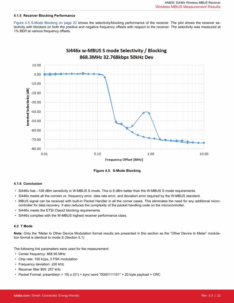
4.1.5 Receiver Blocking Performance
Figure 4.5 S-Mode Blocking on page 22 shows the selectivity/blocking performance of the receiver. The plot shows the receiver se-lectivity with blockers on both the positive and negative frequency offsets with respect to the receiver. The selectivity was measured at1% BER at various frequency offsets.
Figure 4.5. S-Mode Blocking
4.1.6 Conclusion
• Si446x has –108 dBm sensitivity in W-MBUS S mode. This is 8 dBm better than the W-MBUS S mode requirements.• Si446x meets all the corners vs. frequency error, data rate error, and deviation error required by the W-MBUS standard.• MBUS signal can be received with built-in Packet Handler in all the corner cases. This eliminates the need for any additional micro-
controller for data recovery. It also reduces the complexity of the packet handling code on the microcontroller.• Si446x meets the ETSI Class2 blocking requirements.• Si446x complies with the W-MBUS highest receiver performance class.
4.2 T Mode
Note: Only the “Meter to Other Device Modulation format results are presented in this section as the “Other Device to Meter” modula-tion format is identical to mode S (Section 5.1)
The following link parameters were used for the measurement:• Center frequency: 868.95 MHz• Chip rate: 100 kcps, 2 FSK modulation• Frequency deviation: ±50 kHz• Receiver filter BW: 257 kHz• Packet Format: preamble(n = 19) x (01) + sync word “0000111101” + 20 byte payload + CRC
AN805: Si446x Wireless MBUS ReceiverWireless MBUS Measurement Results
silabs.com | Smart. Connected. Energy-friendly. Rev. 0.3 | 22

4.2.1 Receiver Sensitivity
Figure 4.6. T-Mode Receiver Sensitivity
• 0% PER at High RF i/p• The measured sensitivity for <1% PER is –100 dBm• The measured sensitivity for <20% PER is –102 dBm• The measured sensitivity for <80% PER is –104.5 dBm
AN805: Si446x Wireless MBUS ReceiverWireless MBUS Measurement Results
silabs.com | Smart. Connected. Energy-friendly. Rev. 0.3 | 23

4.2.2 Receiver Frequency Error Tolerance
Figure 4.7 T-Mode Receiver Frequency Error Tolerance on page 24 and Figure 4.8 T-Mode Receiver Frequency Error Tolerance onpage 25 show the frequency error tolerance capability of the receiver. The figures show the sensitivity of the receiver measured at80% PER versus frequency offset. Sensitivity vs. frequency offset curves are presented at various Tx signal DR values (nominal, mini-mum, maximum) parameterized with various Tx signal deviation values (nominal, minimum, maximum).
Figure 4.7. T-Mode Receiver Frequency Error Tolerance
The limits are placed at ± 85 ppm offset on the graph. Worst case transmitters (T1) will have a ± 60 ppm accuracy; worst case receivemodes (T2) will have a worst case ± 25 ppm accuracy. Therefore, the sum of the two numbers has been used to determine the limits.
AN805: Si446x Wireless MBUS ReceiverWireless MBUS Measurement Results
silabs.com | Smart. Connected. Energy-friendly. Rev. 0.3 | 24

Figure 4.8. T-Mode Receiver Frequency Error Tolerance
AN805: Si446x Wireless MBUS ReceiverWireless MBUS Measurement Results
silabs.com | Smart. Connected. Energy-friendly. Rev. 0.3 | 25

4.2.3 Receiver Data Rate Error Tolerance
Figure 4.9 T-Mode Receiver Data Rate Error Tolerance on page 26 shows the data rate error tolerance capability of the receiver. Theplot shows the sensitivity of the receiver measured at 80% PER versus the data rate error in kHz.
Figure 4.9. T-Mode Receiver Data Rate Error Tolerance
AN805: Si446x Wireless MBUS ReceiverWireless MBUS Measurement Results
silabs.com | Smart. Connected. Energy-friendly. Rev. 0.3 | 26

4.2.4 Receiver Deviation Error Tolerance
Figure 4.10 T-Mode Receiver Deviation Error Tolerance on page 27 shows the deviation error tolerance capability of the receiver. Theplot shows the sensitivity of the receiver measured at 80% PER versus the deviation error in kHz.
Figure 4.10. T-Mode Receiver Deviation Error Tolerance
AN805: Si446x Wireless MBUS ReceiverWireless MBUS Measurement Results
silabs.com | Smart. Connected. Energy-friendly. Rev. 0.3 | 27

4.2.5 Receiver Blocking Performance
Figure 4.11 T-Mode Receiver Selectivities on page 28shows the selectivity/blocking performance of the receiver. The plots show re-ceiver selectivity with blockers on both the positive and negative frequency offsets with respect to the receiver. The selectivity wasmeasured at 1% BER at various frequency offsets.
Figure 4.11. T-Mode Receiver Selectivities
4.2.6 Conclusion
• Si446x has –104.5 dBm sensitivity in W-MBUS T mode. This is 4.5 dBm better than the W-MBUS T mode requirements.• Si446x meets all the corners (frequency error, data rate error, and deviation error) required by the W-MBUS standard.• MBUS signal can be received with built-in Packet Handler in all the corner cases. This eliminates the need for any additional micro-
controller for data recovery. It also reduces the complexity of the packet handling code on the microcontroller.• Si446x meets the ETSI Class2 blocking requirements.• Si446x complies with the W-MBUS highest receiver performance class.
4.3 R2 Mode
The following link parameters were used for the measurement:• Center frequency: 868.03 MHz• Chip rate: 4.8 kcps, 2 FSK modulation• Frequency deviation: ±6 kHz• Receiver filter BW: 60 kHz• Packet Format: preamble (n = 39) x (01) + sync word “000111011010010110” + 20 byte payload + CRC
AN805: Si446x Wireless MBUS ReceiverWireless MBUS Measurement Results
silabs.com | Smart. Connected. Energy-friendly. Rev. 0.3 | 28

4.3.1 Receiver Sensitivity
Figure 4.12. R-Mode Receiver Sensitivity
• 0% PER at strong RF i/p.• The measured sensitivity for <1% PER is –113 dBm• The measured sensitivity for <20% PER is –115 dBm• The measured sensitivity for <80% PER is –117 dBm
AN805: Si446x Wireless MBUS ReceiverWireless MBUS Measurement Results
silabs.com | Smart. Connected. Energy-friendly. Rev. 0.3 | 29

4.3.2 Receiver Frequency Error Tolerance
Figure 4.13 R-Mode Receiver Frequency Error Tolerance on page 30 shows the frequency error tolerance capability of the receiver.The plot shows the sensitivity of the receiver measured at 80% PER versus frequency offset.
Figure 4.13. R-Mode Receiver Frequency Error Tolerance
Mode R2 is the only mode that is channelized and has a 60 kHz channel spacing specification. Now, let us have a look at a worst caseTx scenario with the largest deviation and maximum frequency offset.
ModBW_max = 2 x deviation_max + DR = 2*7.2 kHz + 6 kbps = 19.4 kHz
single_sided_frequency_offset_max = 20 [ppm] * 868 [MHz] = 17.36 kHz
In such a worst case scenario the Tx signal can span between ± 27.06 kHz (with the ± worst case frequency offset) with regards to thecenter frequency. That only leaves a "slack" of ± 2.94 kHz on the receiver to still comply with the 60 kHz channel spacing. This trans-lates to a ± 3.4 ppm reference accuracy at the Rx side. With the current wording of the standard this is the only way to comply with the60 kHz channel spacing specification.
The limit lines are set to ± 23.4 ppm (± 20 kHz).
AN805: Si446x Wireless MBUS ReceiverWireless MBUS Measurement Results
silabs.com | Smart. Connected. Energy-friendly. Rev. 0.3 | 30

4.3.3 Receiver Data Rate Error Tolerance
Figure 4.14 R-Mode Receiver Data Rate Error Tolerance on page 31 shows the data rate error tolerance capability of the receiver.The plot shows the sensitivity of the receiver measured at 80% PER versus the percentage of data rate error.
Figure 4.14. R-Mode Receiver Data Rate Error Tolerance
AN805: Si446x Wireless MBUS ReceiverWireless MBUS Measurement Results
silabs.com | Smart. Connected. Energy-friendly. Rev. 0.3 | 31

4.3.4 Receiver Deviation Error Tolerance
Figure 4.15 R Mode Receiver Deviation Error Tolerance on page 32 shows the deviation error tolerance capability of the receiver.The plot shows the sensitivity of the receiver measured at 80% PER versus the deviation error in kHz.
Figure 4.15. R Mode Receiver Deviation Error Tolerance
AN805: Si446x Wireless MBUS ReceiverWireless MBUS Measurement Results
silabs.com | Smart. Connected. Energy-friendly. Rev. 0.3 | 32

4.3.5 Receiver Blocking Performance
Figure 4.16 R2 Mode Receiver Selectivity on page 33 shows the selectivity/blocking performance of the receiver. The plot shows thereceiver selectivity with blockers on both the positive and negative frequency offsets with respect to the receiver. The selectivity wasmeasured at 1% BER at various frequency offsets.
Figure 4.16. R2 Mode Receiver Selectivity
4.3.6 Conclusion
• Si446x has –117 dBm sensitivity in W-MBUS R2 mode. This is 12 dBm better than the W-MBUS R2 mode requirements.• Si446x meets all the corners vs. frequency error, data rate error, and deviation error required by the W-MBUS standard.• MBUS signal can be received with built-in Packet Handler in all the corner cases. This eliminates the need for any additional micro-
controller for data recovery. It also reduces the complexity of the packet handling code on the microcontroller.• Si446x meets the ETSI Class2 blocking requirements.• Si446x complies with the W-MBUS highest receiver performance class.
AN805: Si446x Wireless MBUS ReceiverWireless MBUS Measurement Results
silabs.com | Smart. Connected. Energy-friendly. Rev. 0.3 | 33

4.4 C Mode
The following link parameters were used for the measurement:• Direction from meter:
• Center frequency: 868.95 MHz• Chip rate: 100 kcps, 2 FSK modulation• Frequency deviation: ±45 kHz• Receiver filter BW: 214.04 kHz• Packet Format: preamble (n = 16) x (01) + sync word “0101010000111101 0101010011001101” + 20 bytes payload + CRC
• Direction to meter:• Center frequency: 869.525 MHz• Chip rate: 50 kcps, 2 GFSK modulation• Frequency deviation: ±25 kHz• Receiver filter BW: 143.24 kHz• Packet Format: preamble (n = 16) x (01) + sync word “0101010000111101 0101010011001101” + 20 byte payload + CRC
AN805: Si446x Wireless MBUS ReceiverWireless MBUS Measurement Results
silabs.com | Smart. Connected. Energy-friendly. Rev. 0.3 | 34

4.4.1 Receiver Sensitivity
Figure 4.17. C-Mode Receiver Sensitivity
• Direction: Meter to other (C1, C2):• 0% PER at strong RF i/p.• The measured sensitivity for <1% PER is –104 dBm.• The measured sensitivity for <20% PER is –106 dBm.• The measured sensitivity for <80% PER is –109 dBm.
• Direction: Other to meter (C2):• 0% PER at strong RF i/p.• The measured sensitivity for <1% PER is –107 dBm.• The measured sensitivity for <20% PER is –108 dBm.• The measured sensitivity for <80% PER is –111 dBm.
AN805: Si446x Wireless MBUS ReceiverWireless MBUS Measurement Results
silabs.com | Smart. Connected. Energy-friendly. Rev. 0.3 | 35

4.4.2 Receiver Frequency Error Tolerance
Figure 4.18 C Mode Receiver Frequency Error Tolerance from Meter / to Meter on page 36 shows the frequency error tolerance ca-pability of the receiver. The plots show the sensitivity of the receiver measured at 80% PER versus frequency offset.
AN805: Si446x Wireless MBUS ReceiverWireless MBUS Measurement Results
silabs.com | Smart. Connected. Energy-friendly. Rev. 0.3 | 36

Figure 4.18. C Mode Receiver Frequency Error Tolerance from Meter / to Meter
AN805: Si446x Wireless MBUS ReceiverWireless MBUS Measurement Results
silabs.com | Smart. Connected. Energy-friendly. Rev. 0.3 | 37

4.4.3 Receiver Data Rate Error Tolerance
Figure 4.19 C Mode Receiver Data Rate Error Tolerance on page 38 shows the data rate error tolerance capability of the receiver.The plot shows the sensitivity of the receiver measured at 80% PER versus the data rate error in ppm.
Figure 4.19. C Mode Receiver Data Rate Error Tolerance
AN805: Si446x Wireless MBUS ReceiverWireless MBUS Measurement Results
silabs.com | Smart. Connected. Energy-friendly. Rev. 0.3 | 38

4.4.4 Receiver Deviation Error Tolerance
Figure 4.20 C Mode Receiver Deviation Error Tolerance (from Meter / to Meter) on page 39 shows the deviation error tolerance capa-bility of the receiver. The plots show the sensitivity of the receiver measured at 80% PER versus the deviation error in kHz.
AN805: Si446x Wireless MBUS ReceiverWireless MBUS Measurement Results
silabs.com | Smart. Connected. Energy-friendly. Rev. 0.3 | 39

Figure 4.20. C Mode Receiver Deviation Error Tolerance (from Meter / to Meter)
AN805: Si446x Wireless MBUS ReceiverWireless MBUS Measurement Results
silabs.com | Smart. Connected. Energy-friendly. Rev. 0.3 | 40

4.4.5 Receiver Blocking Performance
Figure 4.21 C Mode Receiver Selectivity on page 41 shows the selectivity/blocking performance of the receiver. The plots show thereceiver selectivity with blockers on both the positive and negative frequency offsets with respect to the receiver. The selectivity wasmeasured at 1% BER at various frequency offsets.
AN805: Si446x Wireless MBUS ReceiverWireless MBUS Measurement Results
silabs.com | Smart. Connected. Energy-friendly. Rev. 0.3 | 41

Figure 4.21. C Mode Receiver Selectivity
4.4.6 Conclusion
• Si446x has –109 dBm or –111 dBm sensitivity in W-MBUS C mode (depending on the direction). These are 8 dB and 11 dB betterthan the W-MBUS C mode requirements.
• Si446x meets all the corners vs. frequency error, data rate error, and deviation error required by the W-MBUS standard.• MBUS signal can be received with built-in Packet Handler in all the corner cases. This eliminates the need for any additional micro-
controller for data recovery. It also reduces the complexity of the packet handling code on the microcontroller.• Si446x meets the ETSI Class2 blocking requirements.• Si446x complies with the W-MBUS highest receiver performance class.
4.5 N(1,2)a/b/e/f Mode
The following link parameters were used for the measurement:• Center frequency: 169.40625 MHz• Chip rate: 4.8 kbps, 2 GFSK modulation• Frequency deviation: ±2.4 kHz• Receiver filter BW: 10.33 kHz• Packet Format: preamble(n = 8) x (01) + sync word “11110110 10001101” + 20 bytes payload + CRC
AN805: Si446x Wireless MBUS ReceiverWireless MBUS Measurement Results
silabs.com | Smart. Connected. Energy-friendly. Rev. 0.3 | 42

4.5.1 Receiver Sensitivity
Figure 4.22. N(1,2)a/b/e/f Mode Receiver Sensitivity
• <1% PER at High RF i/p.• The measured sensitivity for <1% PER is –117 dBm.• The measured sensitivity for <20% PER is –118 dBm.• The measured sensitivity for <80% PER is –120.5 dBm.
AN805: Si446x Wireless MBUS ReceiverWireless MBUS Measurement Results
silabs.com | Smart. Connected. Energy-friendly. Rev. 0.3 | 43
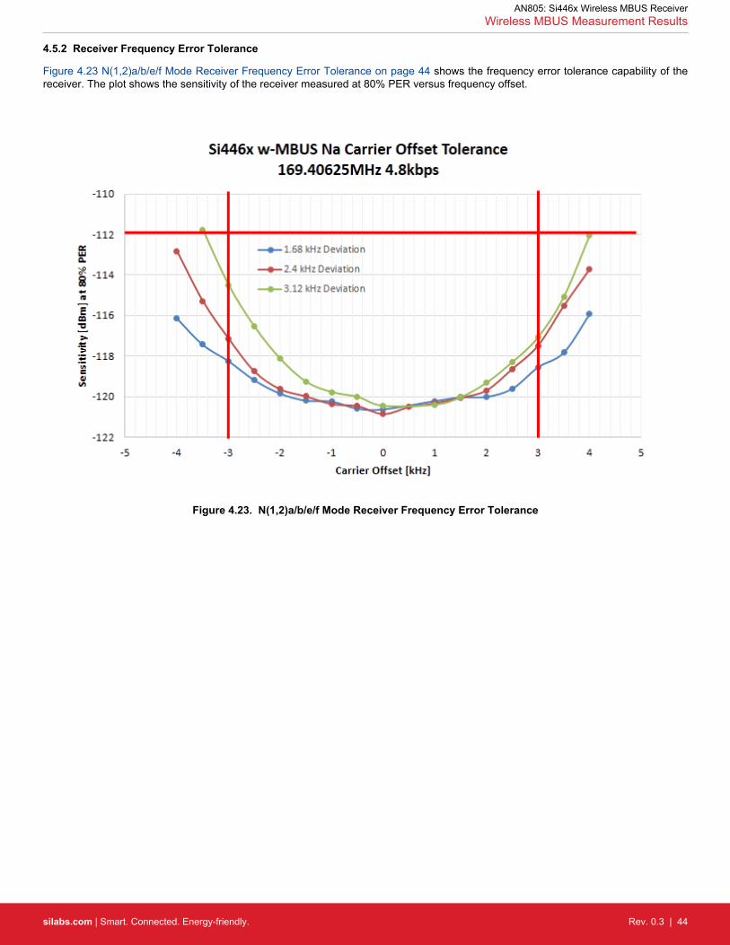
4.5.2 Receiver Frequency Error Tolerance
Figure 4.23 N(1,2)a/b/e/f Mode Receiver Frequency Error Tolerance on page 44 shows the frequency error tolerance capability of thereceiver. The plot shows the sensitivity of the receiver measured at 80% PER versus frequency offset.
Figure 4.23. N(1,2)a/b/e/f Mode Receiver Frequency Error Tolerance
AN805: Si446x Wireless MBUS ReceiverWireless MBUS Measurement Results
silabs.com | Smart. Connected. Energy-friendly. Rev. 0.3 | 44

4.5.3 Receiver Data Rate Error Tolerance
Figure 4.24 N(1,2)a/b/e/f Mode Receiver Data Rate Error Tolerance on page 45 shows the data rate error tolerance capability of thereceiver. The plot shows the sensitivity of the receiver measured at 80% PER versus percentage of data rate error.
Figure 4.24. N(1,2)a/b/e/f Mode Receiver Data Rate Error Tolerance
AN805: Si446x Wireless MBUS ReceiverWireless MBUS Measurement Results
silabs.com | Smart. Connected. Energy-friendly. Rev. 0.3 | 45

4.5.4 Receiver Deviation Error Tolerance
Figure 4.25 N(1,2)a/b/e/f Mode Receiver Deviation Error Tolerance on page 46 shows the deviation error tolerance capability of thereceiver. The plot shows the sensitivity of the receiver measured at 80% PER versus the deviation error in kHz.
Figure 4.25. N(1,2)a/b/e/f Mode Receiver Deviation Error Tolerance
AN805: Si446x Wireless MBUS ReceiverWireless MBUS Measurement Results
silabs.com | Smart. Connected. Energy-friendly. Rev. 0.3 | 46

4.5.5 Receiver Blocking Performance
Figure 4.26 N(1,2)a/b Mode Receiver Selectivity on page 47 shows the selectivity/blocking performance of the receiver. The plotshows the receiver selectivity with blockers on both the positive and negative frequency offsets with respect to the receiver. The selec-tivity was measured at 1% BER at various frequency offsets.
Figure 4.26. N(1,2)a/b Mode Receiver Selectivity
4.5.6 Conclusion
• Si446x has –120.5 dBm sensitivity in W-MBUS N(1,2)a/b/e/f mode. This is 8.5 dB better than the W-MBUS N(1,2)a/b/e/f mode re-quirements.
• Si446x meets all the corners vs. frequency error, data rate error, and deviation error required by the W-MBUS N(1,2)a/b/e/f stand-ard.
• MBUS signal can be received with built-in Packet Handler in all the corner cases. This eliminates the need for any additional micro-controller for data recovery. It also reduces the complexity of the packet handling code on the microcontroller.
• Si446x meets the ETSI Class2 blocking requirements.• Si446x complies with the W-MBUS highest receiver performance class.
4.6 N(1,2)c/d Mode
The following link parameters were used for the measurement:• Center frequency: 169.43125 MHz• Chip rate: 2.4 kbps, 2 GFSK modulation• Frequency deviation: ±2.4 kHz• Receiver Filter BW: 11.58 kHz• Packet Format: preamble (n = 8) x (01) + sync word “11110110 10001101” + 20 bytes payload + CRC
AN805: Si446x Wireless MBUS ReceiverWireless MBUS Measurement Results
silabs.com | Smart. Connected. Energy-friendly. Rev. 0.3 | 47

4.6.1 Receiver Sensitivity
Figure 4.27. Nc/d Mode Receiver Sensitivity
• <1% PER at High RF i/p.• The measured sensitivity for <1% PER is –116 dBm.• The measured sensitivity for <20% PER is –118 dBm.• The measured sensitivity for <80% PER is –120.5 dBm.
AN805: Si446x Wireless MBUS ReceiverWireless MBUS Measurement Results
silabs.com | Smart. Connected. Energy-friendly. Rev. 0.3 | 48

4.6.2 Receiver Frequency Error Tolerance
Figure 4.28 Nc/d Mode Receiver Frequency Error Tolerance on page 49 shows the frequency error tolerance capability of the receiv-er. The plot shows the sensitivity of the receiver measured at 80% PER versus frequency offset.
Figure 4.28. Nc/d Mode Receiver Frequency Error Tolerance
The limits are placed at ± 21 ppm offset on the graph.Worst case transmitters will have a ±11.5 ppm accuracy. In such a narrowbandworst case receive modes can have a worst case ±9.5 ppm accuracy. Therefore, the sum of the two numbers has been used to deter-mine the limits.
AN805: Si446x Wireless MBUS ReceiverWireless MBUS Measurement Results
silabs.com | Smart. Connected. Energy-friendly. Rev. 0.3 | 49

4.6.3 Receiver Data Rate Error Tolerance
Figure 4.29 Nc/d Mode Receiver Data Rate Error Tolerance on page 50 shows the data rate error tolerance capability of the receiver.The plot shows the sensitivity of the receiver measured at 80% PER versus the percentage of data rate error.
Figure 4.29. Nc/d Mode Receiver Data Rate Error Tolerance
AN805: Si446x Wireless MBUS ReceiverWireless MBUS Measurement Results
silabs.com | Smart. Connected. Energy-friendly. Rev. 0.3 | 50

4.6.4 Receiver Deviation Error Tolerance
Figure 4.30 Nc/d Mode Receiver Deviation Error Tolerance on page 51 shows the deviation error tolerance capability of the receiver.The plot shows the sensitivity of the receiver measured at 80% PER versus the deviation error in Hz.
Figure 4.30. Nc/d Mode Receiver Deviation Error Tolerance
AN805: Si446x Wireless MBUS ReceiverWireless MBUS Measurement Results
silabs.com | Smart. Connected. Energy-friendly. Rev. 0.3 | 51

4.6.5 Receiver Blocking Performance
Figure 4.31 Nc/d Mode Receiver Selectivity on page 52 shows the selectivity/blocking performance of the receiver. The plot showsthe receiver selectivity with blockers on both the positive and negative frequency offsets with respect to the receiver. The selectivity wasmeasured at 1% BER at various frequency offsets.
Figure 4.31. Nc/d Mode Receiver Selectivity
4.6.6 Conclusion
• Si446x has –120.5 dBm sensitivity in W-MBUS Nc/d modes, which is 5.5 dB better than the W-MBUS Nc/d mode requirements.• Si446x meets all the corners vs. frequency error, data rate error, and deviation error required by the W-MBUS standard.• MBUS signal can be received with built-in Packet Handler in all the corner cases. This eliminates the need for any additional micro-
controller for data recovery. It also reduces the complexity of the packet handling code on the microcontroller.• Si446x meets the ETSI Class2 blocking requirements.• Si446x complies with the W-MBUS highest receiver performance class.
4.7 N2g Mode
The following link parameters were used for the measurement:• Center frequency: 169.4375 MHz• Chip rate: 9.6 kcps, 4 GFSK modulation• Frequency deviation: ± 2.4 kHz• Receiver filter BW: 26 kHz• Packet Format: preamble (n=8) x (AD) + sync word “DDDDADDA DAAADDAD” + 20 bytes payload + CRC
Data transmitted using 4GFSK modulation shall be NRZ encoded, with the lowest frequency corresponding to binary “01” (symbol A),the second frequency corresponding to binary “00” (B), the third frequency corresponding to binary “10” (C) and the highest frequencycorresponding to binary “11” (D).
AN805: Si446x Wireless MBUS ReceiverWireless MBUS Measurement Results
silabs.com | Smart. Connected. Energy-friendly. Rev. 0.3 | 52

4.7.1 Receiver Sensitivity
Figure 4.32. N2g Mode Receiver Sensitivity
• The measured sensitivity for <1% PER is –108 dBm.• The measured sensitivity for <20% PER is –110 dBm.• The measured sensitivity for <80% PER is –113 dBm
AN805: Si446x Wireless MBUS ReceiverWireless MBUS Measurement Results
silabs.com | Smart. Connected. Energy-friendly. Rev. 0.3 | 53

4.7.2 Receiver Frequency Error Tolerance
Figure 4.33 N2g Mode Receiver Frequency Error Tolerance on page 54 shows the frequency error tolerance capability of the receiv-er. The plot shows the sensitivity of the receiver measured at 80% PER versus frequency offset.
Figure 4.33. N2g Mode Receiver Frequency Error Tolerance
AN805: Si446x Wireless MBUS ReceiverWireless MBUS Measurement Results
silabs.com | Smart. Connected. Energy-friendly. Rev. 0.3 | 54

4.7.3 Receiver Deviation Error Tolerance
Figure 4.34 N2g Mode Receiver Deviation Error Tolerance on page 55 shows the deviation error tolerance capability of the receiver.The plot shows the sensitivity of the receiver measured at 80% PER versus the deviation error in Hz.
Figure 4.34. N2g Mode Receiver Deviation Error Tolerance
AN805: Si446x Wireless MBUS ReceiverWireless MBUS Measurement Results
silabs.com | Smart. Connected. Energy-friendly. Rev. 0.3 | 55

4.7.4 Receiver Blocking Performance
Figure 4.35 N2g Mode Receiver Selectivity on page 56 shows the selectivity/blocking performance of the receiver. The plot shows thereceiver selectivity with blockers on both the positive and negative frequency offsets with respect to the receiver. The selectivity wasmeasured at 1% BER at various frequency offsets.
Figure 4.35. N2g Mode Receiver Selectivity
4.7.5 Conclusion
• Si446x has –113 dBm sensitivity in W-MBUS N2g modes, which is 9 dB better than the W-MBUS N2g mode requirements.• Si446x meets all the corners vs. frequency error, data rate error, and deviation error required by the WMBUS standard.• MBUS signal can be received with built-in Packet Handler in all the corner cases. This eliminates the need for any additional micro-
controller for data recovery. It also reduces the complexity of the packet handling code on the microcontroller.• Si446x meets the ETSI Class2 blocking requirements.• Si446x complies with the W-MBUS highest receiver performance class.
4.8 F Mode
The following link parameters were used for the measurement:• Center frequency: 433.82 MHz• Chip rate: 2.4 kcps, 2 FSK modulation• Frequency deviation: ±5.5 kHz• Receiver Filter BW: 46.3 kHz• Packet Format: preamble (n = 39) x (01) + sync word “000111010110100101” + 20 bytes payload + CRC
AN805: Si446x Wireless MBUS ReceiverWireless MBUS Measurement Results
silabs.com | Smart. Connected. Energy-friendly. Rev. 0.3 | 56

4.8.1 Receiver Sensitivity
Figure 4.36. F Mode Receiver Sensitivity
• 0% PER at High RF i/p with 32 bit preamble• The measured sensitivity for <1% PER is –114 dBm.• The measured sensitivity for <20% PER is –117 dBm.• The measured sensitivity for <80% PER is –118.5 dBm.
AN805: Si446x Wireless MBUS ReceiverWireless MBUS Measurement Results
silabs.com | Smart. Connected. Energy-friendly. Rev. 0.3 | 57

4.8.2 Receiver Frequency Error Tolerance
Figure 4.37 F Mode Receiver Frequency Error Tolerance on page 58 shows the frequency error tolerance capability of the receiver.The plot shows the sensitivity of the receiver measured at 80% PER versus frequency offset.
Figure 4.37. F Mode Receiver Frequency Error Tolerance
AN805: Si446x Wireless MBUS ReceiverWireless MBUS Measurement Results
silabs.com | Smart. Connected. Energy-friendly. Rev. 0.3 | 58

4.8.3 Receiver Data Rate Error Tolerance
Figure 4.38 F Mode Receiver Data Rate Error Tolerance on page 59 shows the data rate error tolerance capability of the receiver.The plot shows the sensitivity of the receiver measured at 80% PER versus the data rate error in ppm.
Figure 4.38. F Mode Receiver Data Rate Error Tolerance
AN805: Si446x Wireless MBUS ReceiverWireless MBUS Measurement Results
silabs.com | Smart. Connected. Energy-friendly. Rev. 0.3 | 59

4.8.4 Receiver Deviation Error Tolerance
Figure 4.39 F Mode Receiver Deviation Error Tolerance on page 60 shows the deviation error tolerance capability of the receiver. Theplot shows the sensitivity of the receiver measured at 80% PER versus the deviation error in kHz.
Figure 4.39. F Mode Receiver Deviation Error Tolerance
AN805: Si446x Wireless MBUS ReceiverWireless MBUS Measurement Results
silabs.com | Smart. Connected. Energy-friendly. Rev. 0.3 | 60

4.8.5 Receiver Blocking Performance
Figure 4.40 F Mode Receiver Selectivity on page 61 shows the selectivity/blocking performance of the receiver. The plot shows thereceiver selectivity with blockers on both the positive and negative frequency offsets with respect to the receiver. The selectivity wasmeasured at 1% BER at various frequency offsets.
Figure 4.40. F Mode Receiver Selectivity
4.8.6 Conclusion
• Si446x has –118.5 dBm sensitivity in W-MBUS F mode. This is 2.5 dB better than the W-MBUS F mode requirements.• Si446x meets all the corners vs. frequency error, data rate error, and deviation error required by the W-MBUS standard.• MBUS signal can be received with built-in Packet Handler in all the corner cases. This eliminates the need for any additional micro-
controller for data recovery. It also reduces the complexity of the packet handling code on the microcontroller.• Si446x meets the ETSI Class2 blocking requirements.• Si446x complies with the W-MBUS highest receiver performance class. Complies with the W-MBUS highest receiver performance
class.
AN805: Si446x Wireless MBUS ReceiverWireless MBUS Measurement Results
silabs.com | Smart. Connected. Energy-friendly. Rev. 0.3 | 61

5. Document Change List
5.1 Revision 0.1 to Revision 0.2
• Add clarification regarding the HW platform and tools for configuring the radio.
5.2 Revision 0.2 to Revision 0.3
• All the data was updated for Rev C based on the EN13757-4-2013 w-MBUS standard.
AN805: Si446x Wireless MBUS ReceiverDocument Change List
silabs.com | Smart. Connected. Energy-friendly. Rev. 0.3 | 62

DisclaimerSilicon Laboratories intends to provide customers with the latest, accurate, and in-depth documentation of all peripherals and modules available for system and software implementers using or intending to use the Silicon Laboratories products. Characterization data, available modules and peripherals, memory sizes and memory addresses refer to each specific device, and "Typical" parameters provided can and do vary in different applications. Application examples described herein are for illustrative purposes only. Silicon Laboratories reserves the right to make changes without further notice and limitation to product information, specifications, and descriptions herein, and does not give warranties as to the accuracy or completeness of the included information. Silicon Laboratories shall have no liability for the consequences of use of the information supplied herein. This document does not imply or express copyright licenses granted hereunder to design or fabricate any integrated circuits. The products must not be used within any Life Support System without the specific written consent of Silicon Laboratories. A "Life Support System" is any product or system intended to support or sustain life and/or health, which, if it fails, can be reasonably expected to result in significant personal injury or death. Silicon Laboratories products are generally not intended for military applications. Silicon Laboratories products shall under no circumstances be used in weapons of mass destruction including (but not limited to) nuclear, biological or chemical weapons, or missiles capable of delivering such weapons.
Trademark InformationSilicon Laboratories Inc., Silicon Laboratories, Silicon Labs, SiLabs and the Silicon Labs logo, CMEMS®, EFM, EFM32, EFR, Energy Micro, Energy Micro logo and combinations thereof, "the world’s most energy friendly microcontrollers", Ember®, EZLink®, EZMac®, EZRadio®, EZRadioPRO®, DSPLL®, ISOmodem ®, Precision32®, ProSLIC®, SiPHY®, USBXpress® and others are trademarks or registered trademarks of Silicon Laboratories Inc. ARM, CORTEX, Cortex-M3 and THUMB are trademarks or registered trademarks of ARM Holdings. Keil is a registered trademark of ARM Limited. All other products or brand names mentioned herein are trademarks of their respective holders.
http://www.silabs.com
Silicon Laboratories Inc.400 West Cesar ChavezAustin, TX 78701USA
Simpilcity StudioOne-click access to MCU tools, documentation, software, source code libraries & more. Available for Windows, Mac and Linux!
www.silabs.com/simplicity
MCU Portfoliowww.silabs.com/mcu
SW/HWwww.silabs.com/simplicity
Qualitywww.silabs.com/quality
Support and Communitycommunity.silabs.com
63


![MBus: A Fully Synthesizable Low-power Portable ... › content › pubs › lee16mbus.pdfsensor nodes, a new chip-to-chip bus interconnect, referred to as MBus, is proposed in [11]](https://img.pdfslide.us/doc/110x75/60c96eb99c109f62dc4147a9/mbus-a-fully-synthesizable-low-power-portable-a-content-a-pubs-a-lee16mbuspdf.jpg)