Embed Size (px)
Citation preview
Experiments in Nuclear Science
AN34 Laboratory Manual Third Edition, Revised
Introduction to Theory and Basic Applications
Alpha, Beta, Gamma, X-Ray, and NeutronDetectors and Associated Electronics
Published September 1987.

PrefaceThe series of experiments included in this Laboratory Manual provide an introduction to the varioustechniques that are currently used to study nuclear science and a framework to help the student learn. Themethodology, list of equipment, and step-by-step instructions that are needed are included in eachexperiment, together with sufficient reference material and theoretical information about the experimentto help the student interpret results.
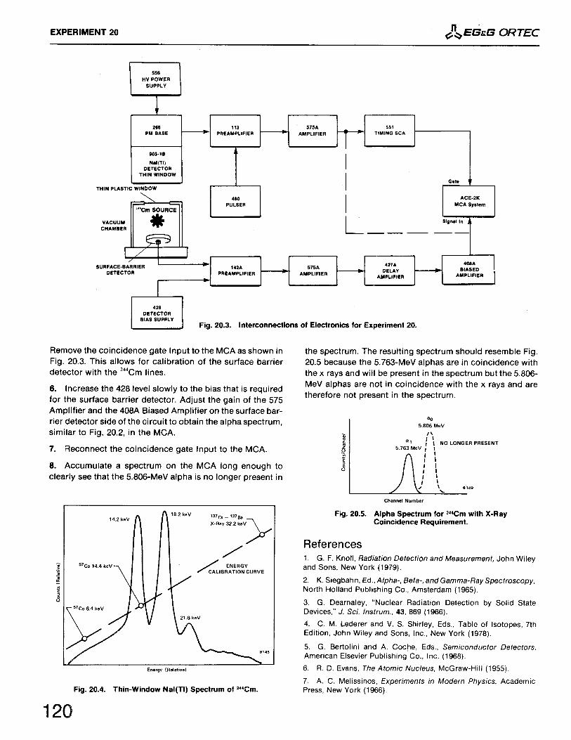
EG&G ORTEC has tried to consider all major disciplines that are involved in nuclear science. Theseinclude physics, chemistry, biology, radiopharmacy, nuclear engineering, and other specialized nucleartechnologies. By consulting many sources, EG&G ORTEC has determined which of these experiments aremost appropriate to each discipline; the sources include university professors, appropriate texts,experimental manuals, and the published recommendations of the U.S. Department of Energy (DOE) andother government agencies. From these studies, EG&G ORTEC recommends the following basicexperiment groups for each of the major disciplines:
PhysicsChemistryBiologyRadiopharmacyNuclear EngineeringNuclear Technology
1 through 21, and 23 through 26.1 through 6, and 12, 17, 23, 24, and 26.1 through 7, and 12, 17, 22, 23, and 24.1 through 6, and 17, 22, 23, and 24.1 through 9, and 12, 13, 14, 15, 17, and 23 through 26.1 through 6, and 12, 17, 22, 23, and 24.
The series of experiments that are appropriate to nuclear technology are also appropriate for nucleartechnician training. Other combinations of experiments can be derived for use in other fields of interestsuch as environmental studies, medical research, quality control and many more in the rapidly growing listof nuclear applications.
Most of the 26 experiments are divided into parts that can be completed in an average time of 30 to 45minutes and can be performed independently. For example, Experiment 3 deals with gamma-rayspectroscopy and includes Experiments 3.1 through 3.10. All experiments that are to be made, however,should be done in sequence. The experiments are provided for educational purposes and can be duplicatedfor class use as desired.
A complete nuclear laboratory, or one that is designed to serve a given area, can be set up with the aid ofthe information that is furnished in this Laboratory Manual.
EG&G ORTEC hopes that this manual will benefit you in your Nuclear Science Program.
AcknowledgementsEG&G ORTEC wishes to thank the author, Professor Jerome L. Duggan, Texas State University, forwriting these experiments and for his continued support of this effort from rough draft to publication.EG&G ORTEC also wishes to thank university professors all over the world for their comments andsuggestions.
The author wishes to thank Professor Dollard Desmarais of the University of Alberta, Canada, for hisassistance with Experiments 21, 25, and 26. He also wishes to thank the many university professorsthroughout the world who have performed the experiments with their students in the first two editions ofthis manual and were kind enough to send their comments and suggestions to us for consideration in ourrevisions.
AN34 Table of Contents
Errata Obsolete Model Replacements
Safe Handling of Radioactive Sources
Experiment 11.11.21.3
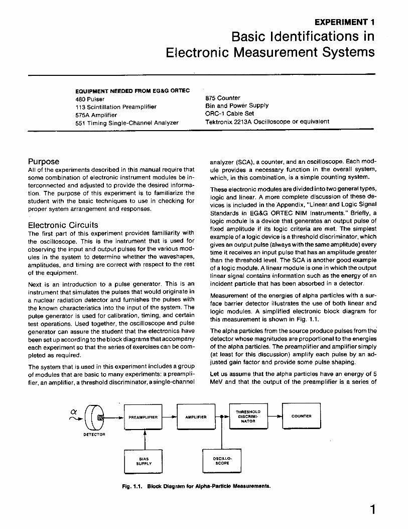
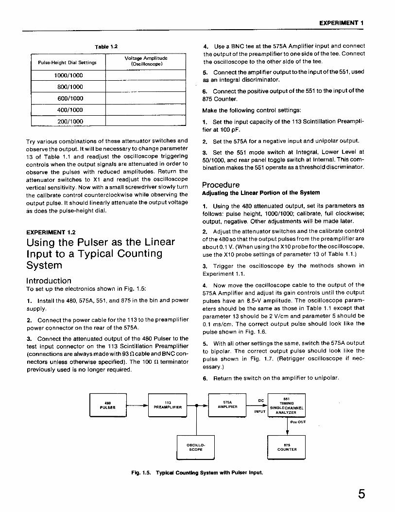
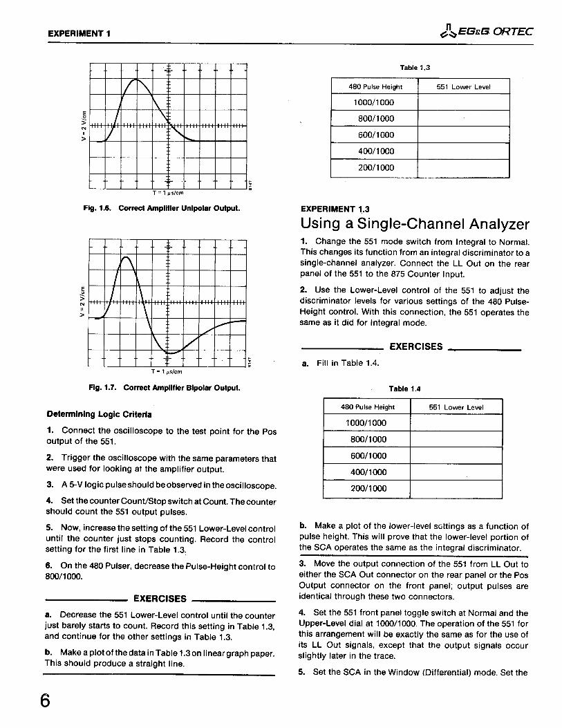
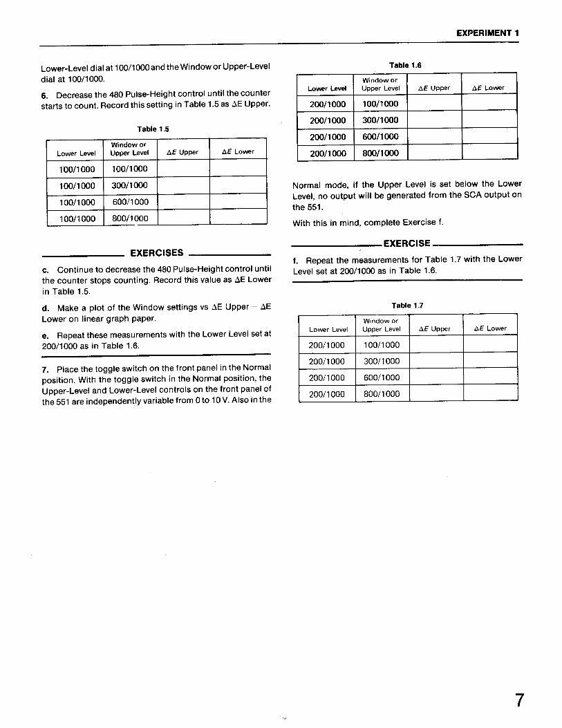
Basic Identification in Electronic Measurement SystemsObserving the Direct and Attenuated Outputs of the Pulser Using the Pulser as the Linear Input to a Typical Counting System Using a Single-Channel Analyzer
Experiment 22.12.22.32.42.52.6
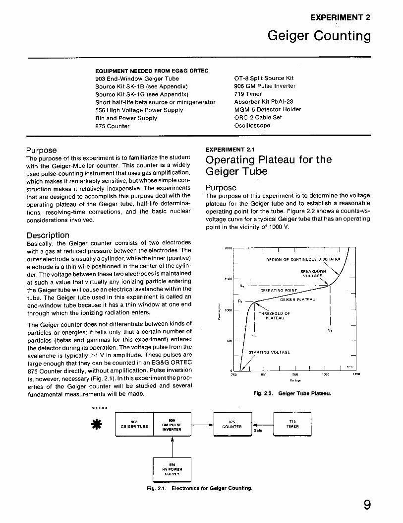
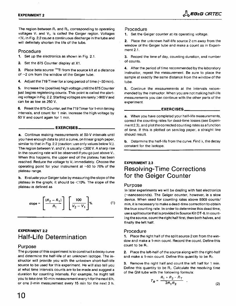
Geiger CountingOperating Plateau for the Geiger Tube Half-Life Determination Resolving-Time Corrections for the Geiger Counter Linear Absorption Coefficient Inverse Square Law Counting Statistics
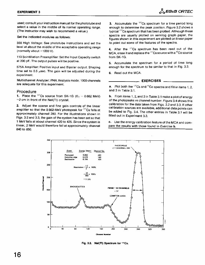
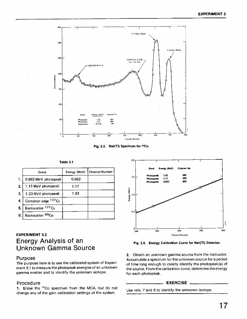
Experiment 33.13.23.33.43.53.63.73.83.9
3.10
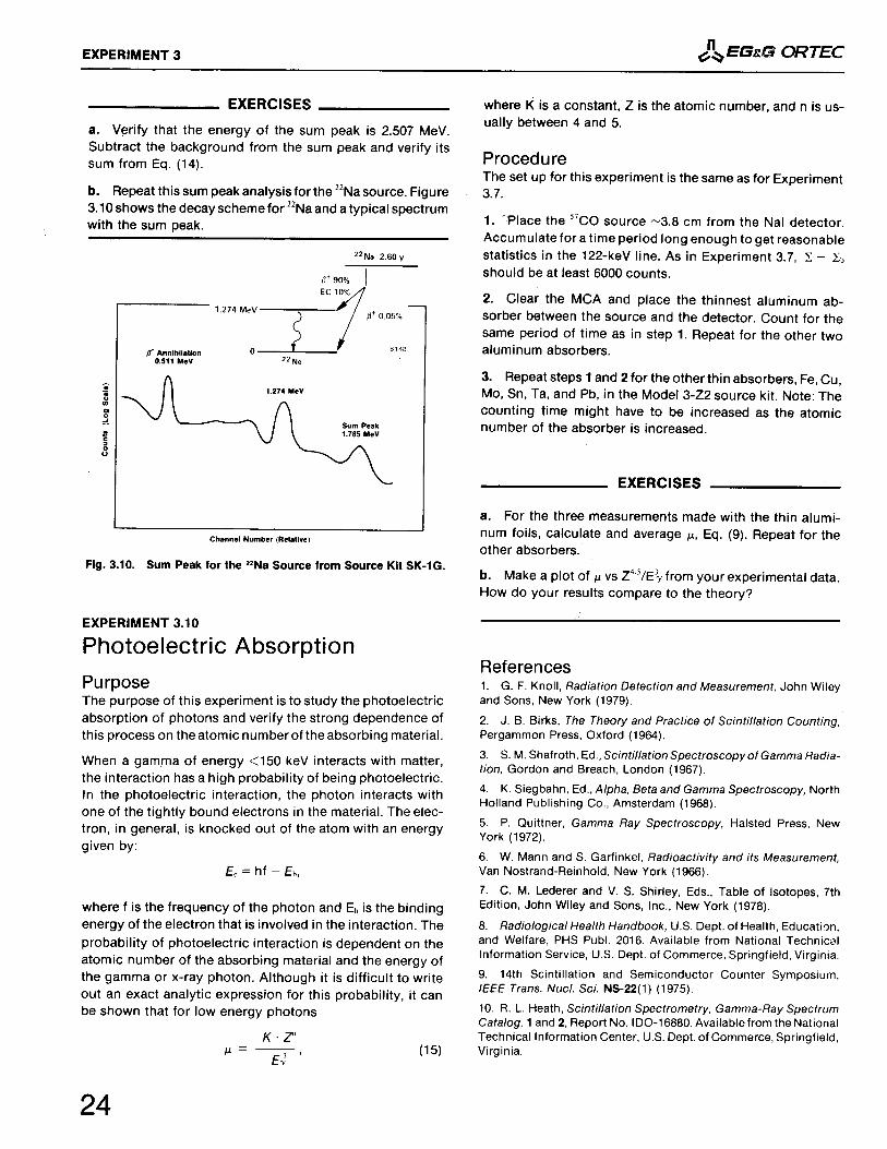
Gamma-Ray Spectroscopy Using NaI(Tl)Energy Calibration Energy Analysis of an Unknown Gamma Source Spectrum Analysis of 60Co and 137Cs Energy Resolution Activity of a Gamma Emitter (Relative Method) Activity of a Gamma Emitter (Absolute Method) Mass Absorption Coefficient The Linear Gate in Gamma-Ray Spectroscopy Sum Peak Analysis Photoelectric Absorption
Experiment 44.14.24.34.44.54.6
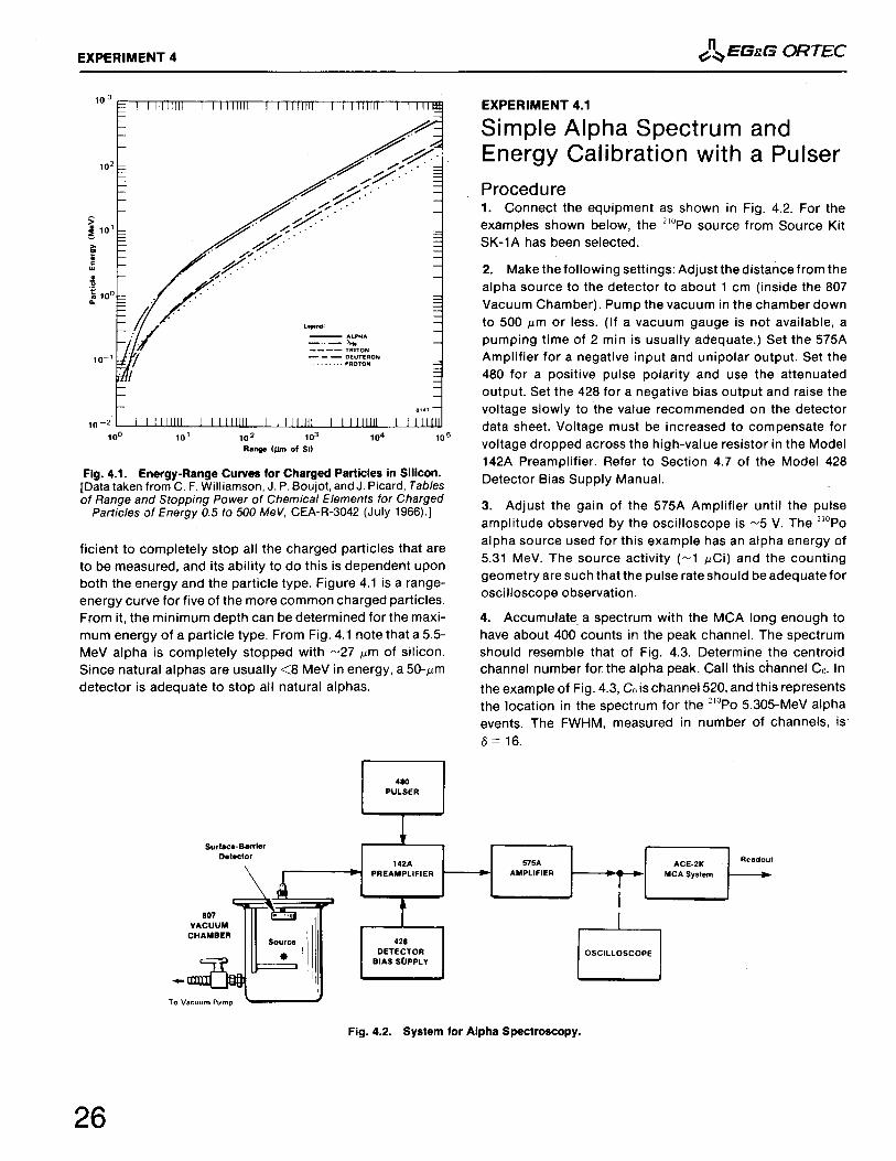
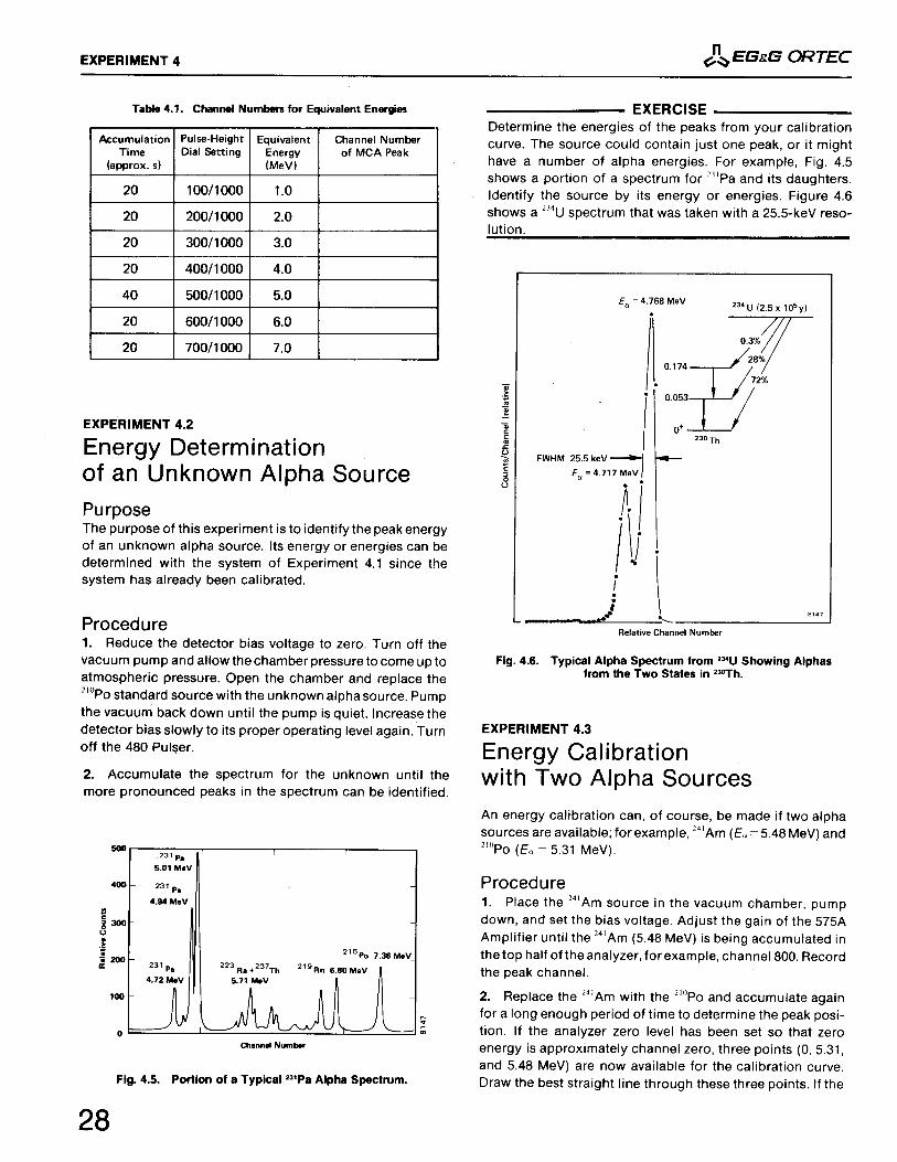
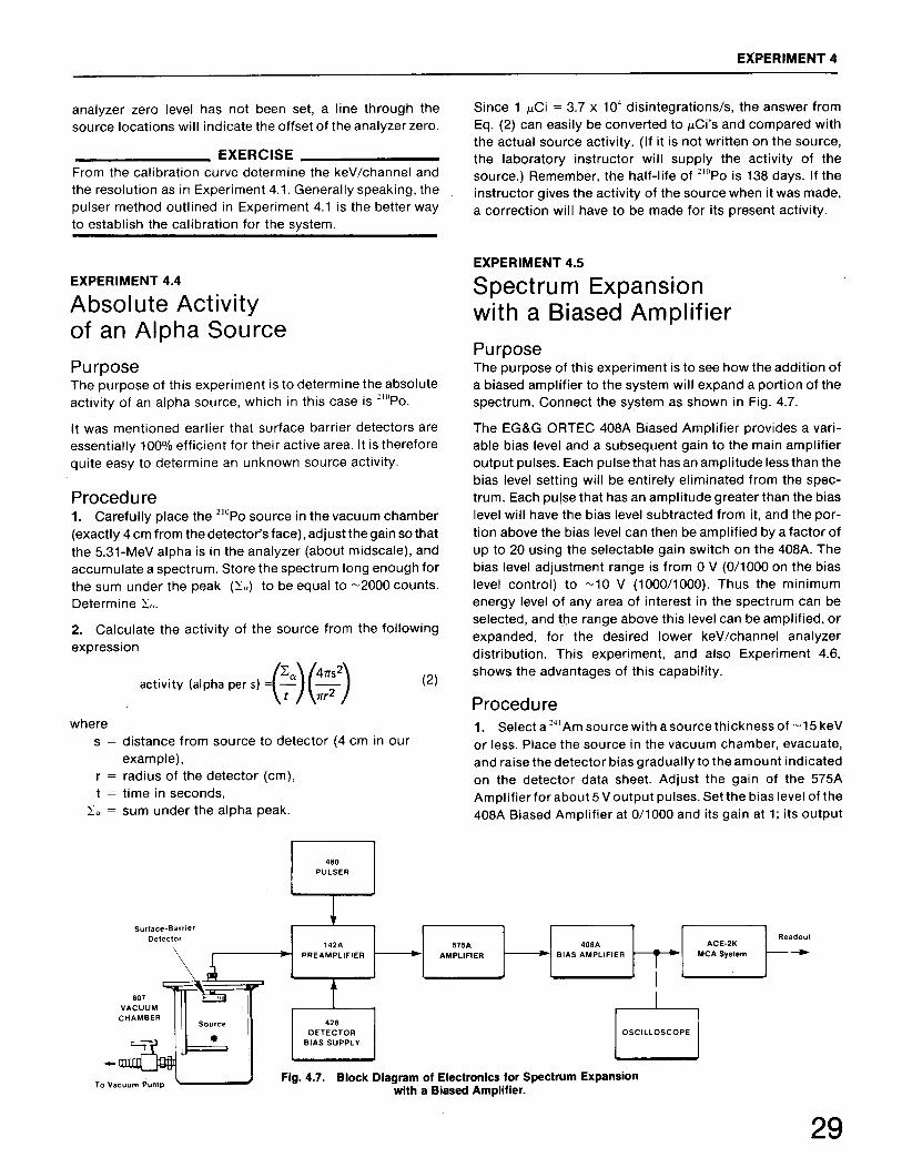
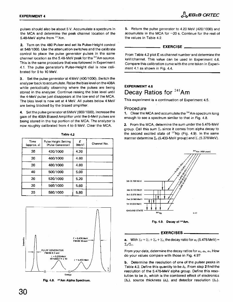
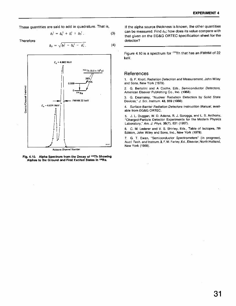
Alpha Spectroscopy with Surface Barrier DetectorsSimple Alpha Spectrum and Energy Calibration with a Pulser Energy Determination of an Unknown Alpha Source Energy Calibration with Two Alpha Sources Absolute Activity of an Alpha Source Spectrum Expansion with a Biased Amplifier Decay Ratios for 241Am
Experiment 55.15.2
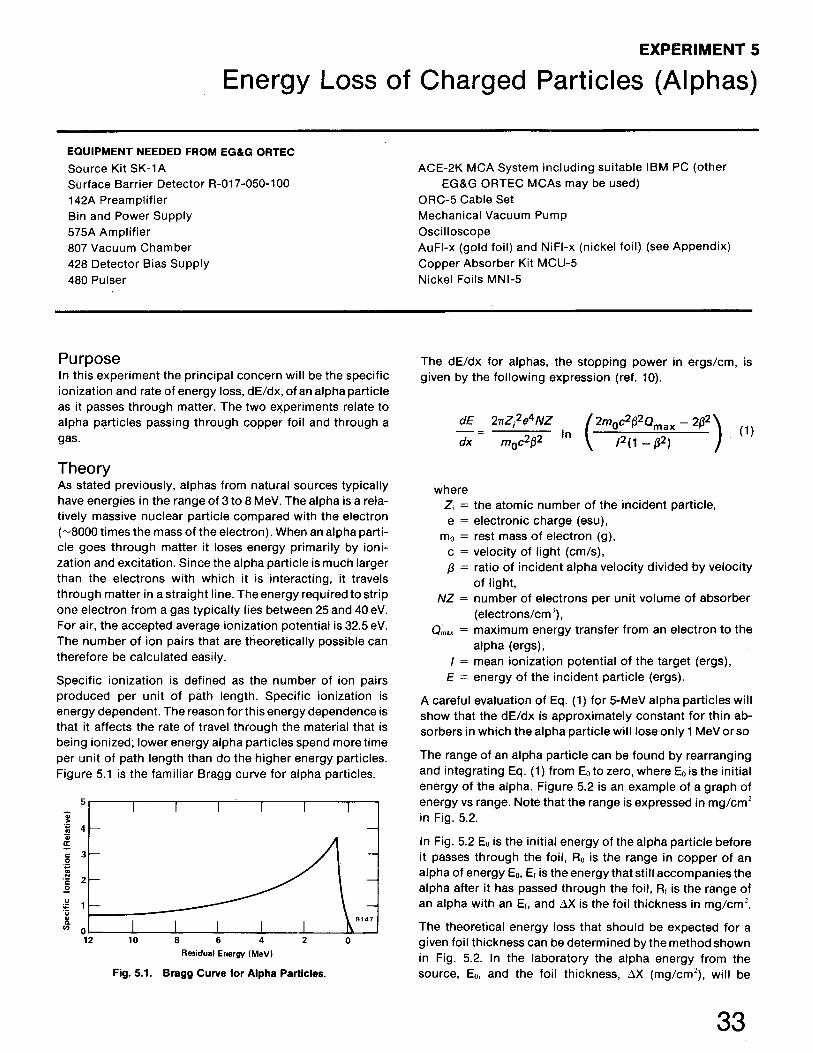
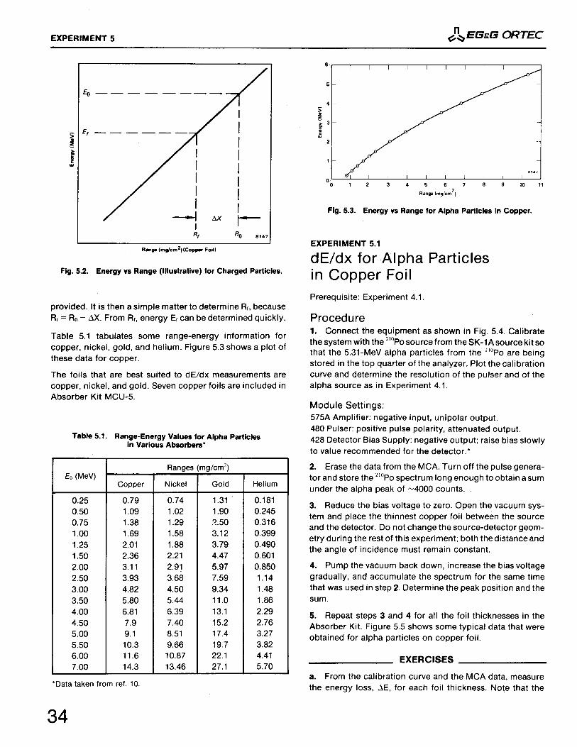
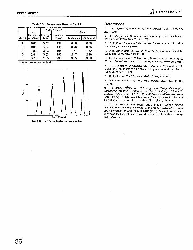
Energy Loss of Charged Particles (Alphas)dE/dx for Alpha Particles in Copper Foil dE/dx for Alpha Particles in Gas
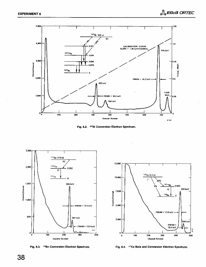
Experiment 66.16.2
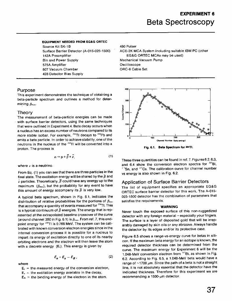
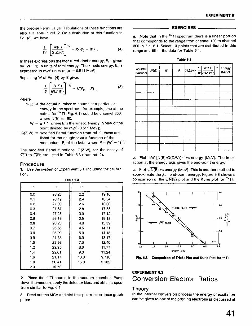
Beta SpectroscopyCalibration with a Pulser Beta End-Point Determination for 204Tl
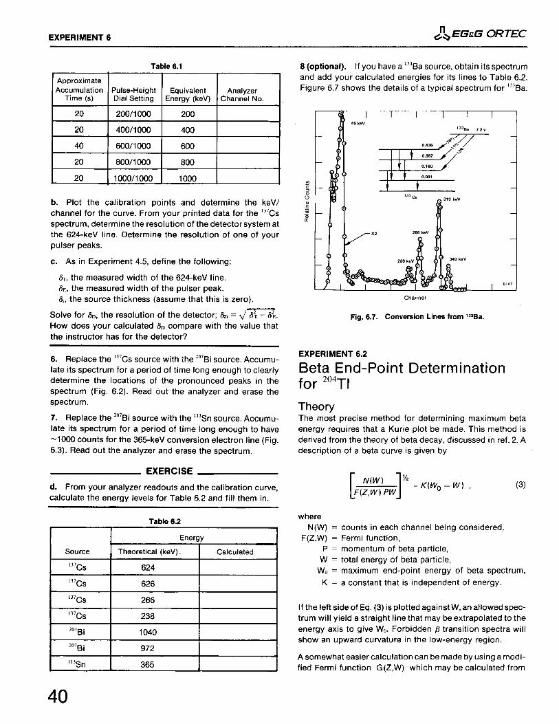
6.3 Conversion Electron Ratios
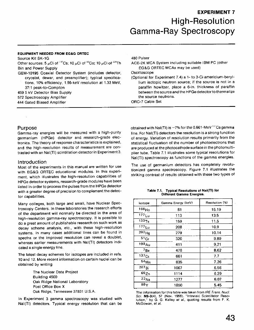
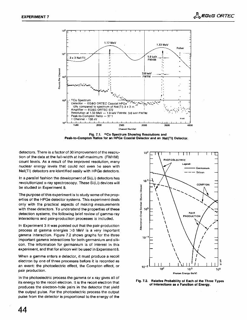
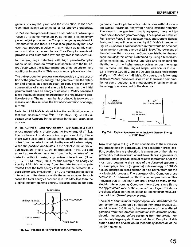
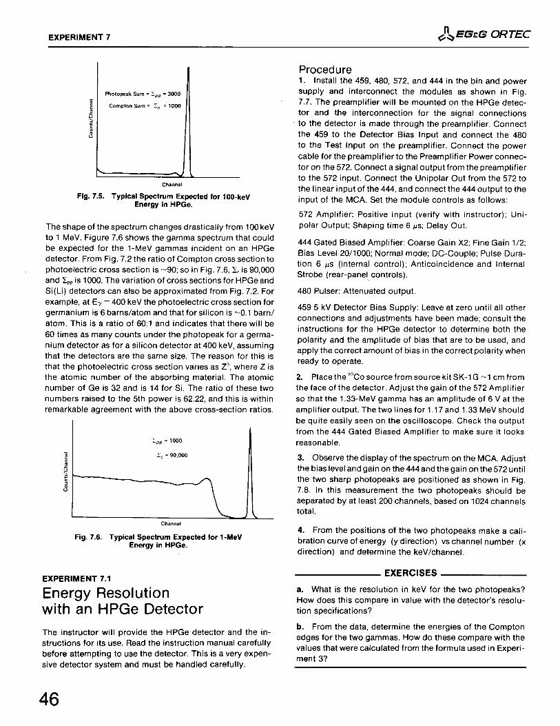
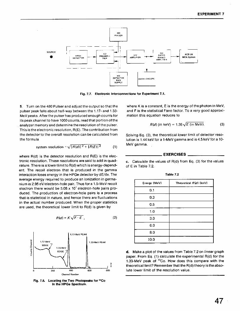
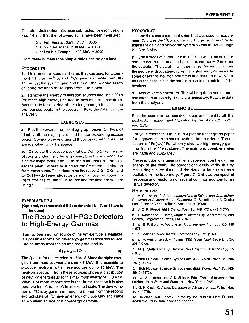
Experiment 77.17.27.37.4
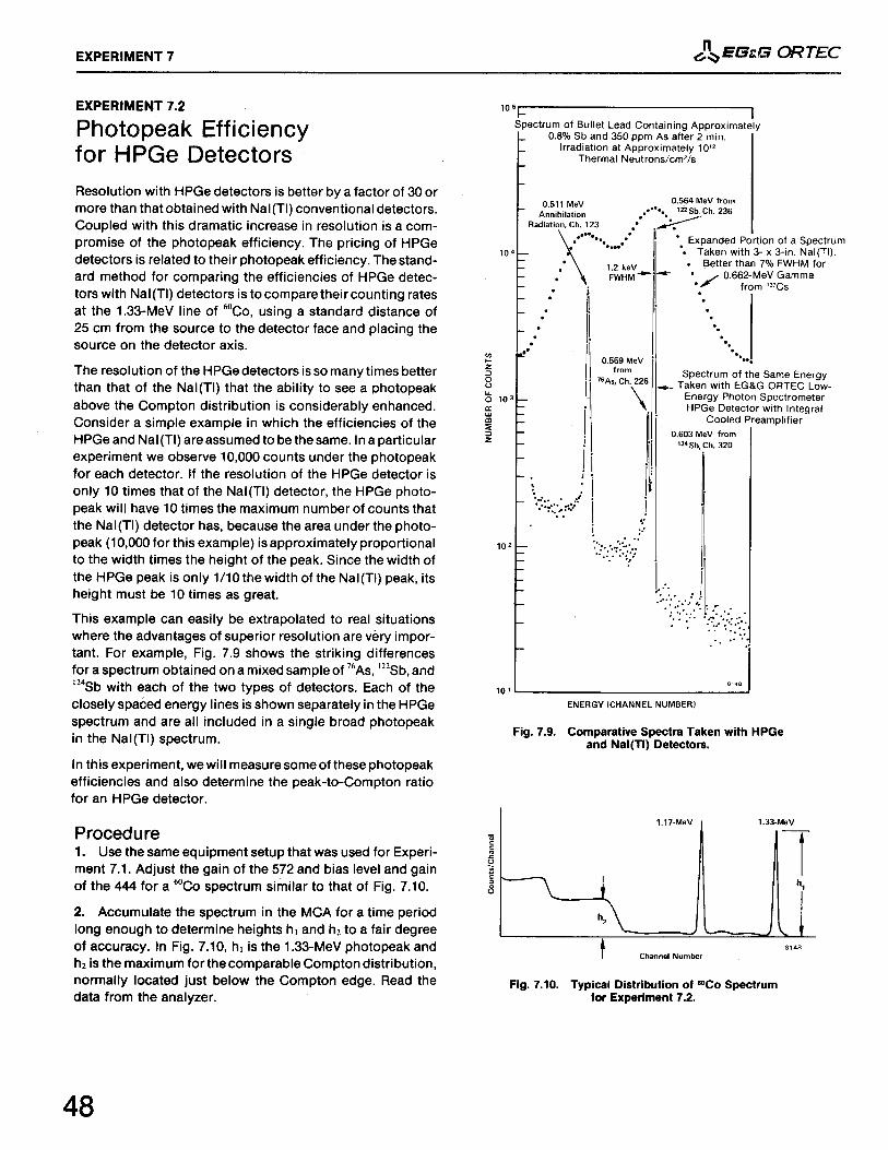
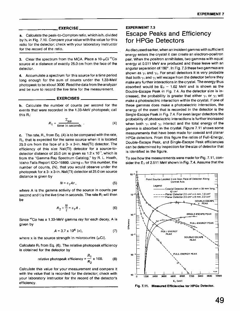
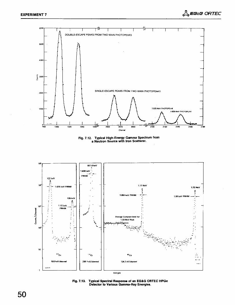
High-Resolution Gamma-Ray SpectroscopyEnergy Resolution with an HPGe Detector Photopeak Efficiency for HPGe Detectors Escape Peaks and Efficiency for HPGe Detectors The Response of HPGe Detectors to High-Energy Gammas
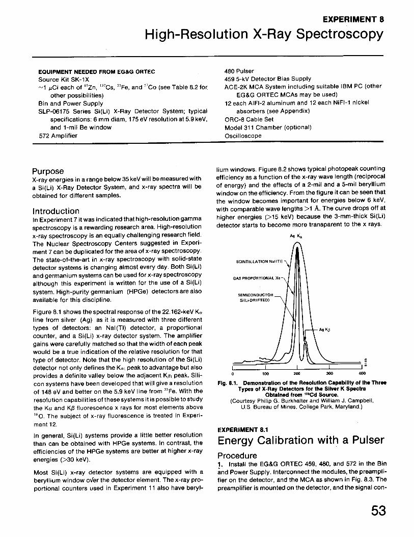
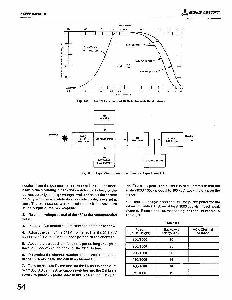
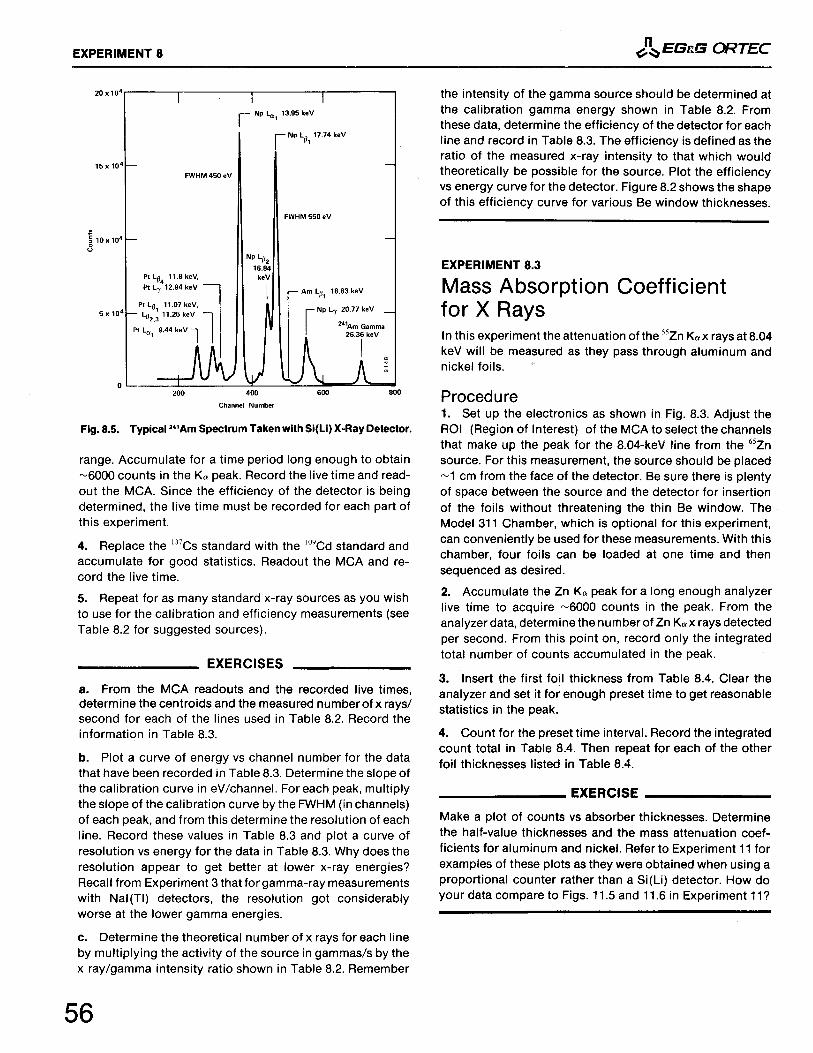
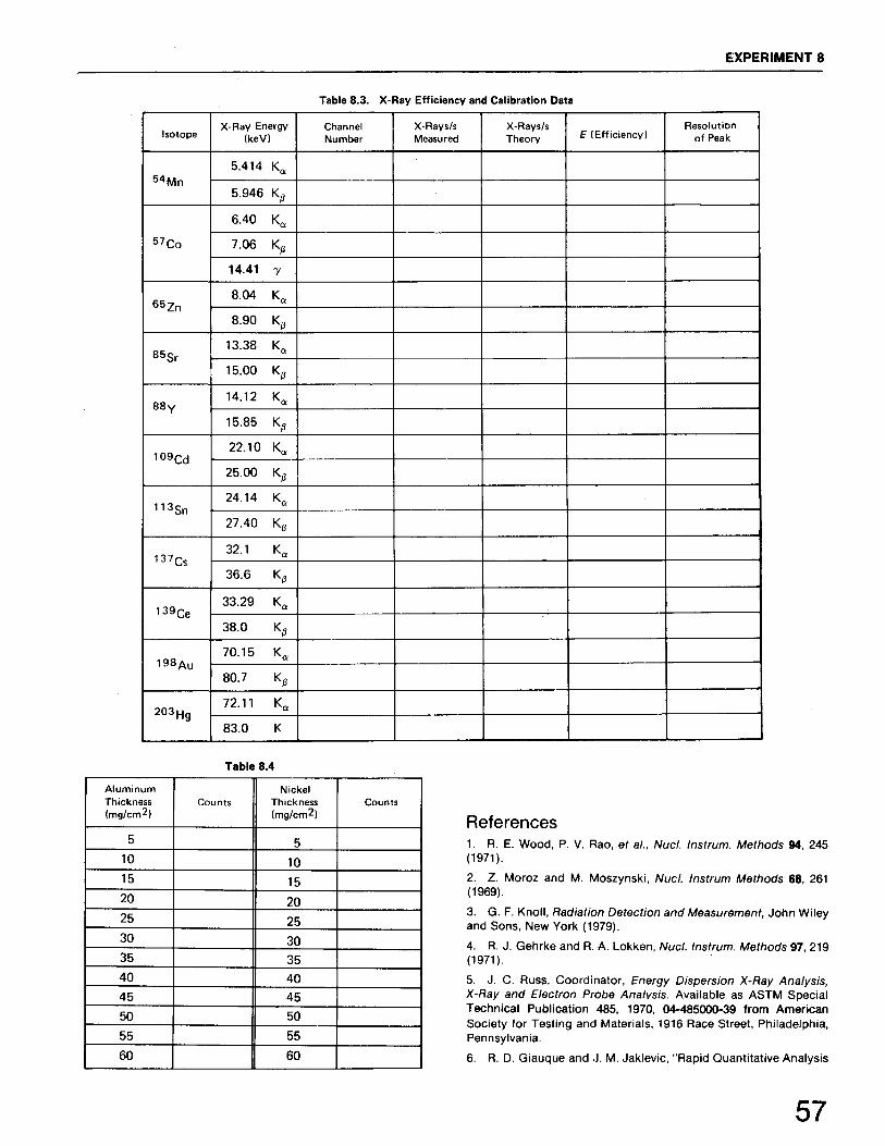
Experiment 88.18.28.3
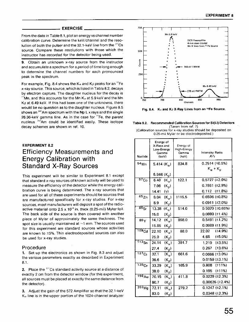
High-Resolution X-Ray SpectroscopyEnergy Calibration with a Pulser Efficiency Measurements and Energy Calibration with Standard X-Ray Sources Mass Absorption Coefficient for X Rays
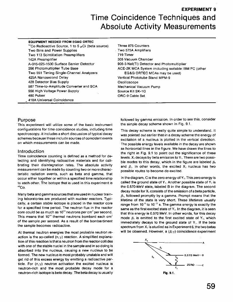
Experiment 99.19.29.3
Time Coincidence Techniques and Absolute Activity MeasurementsSimple Fast Coincidence Fast Coincidence and the Time-to-Amplitude Converter Determination of Absolute Activity by the Coincidence Method
Experiment10
10.110.210.310.4
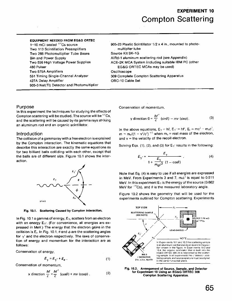
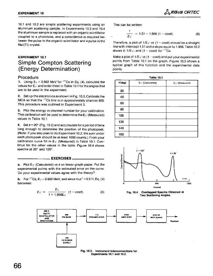
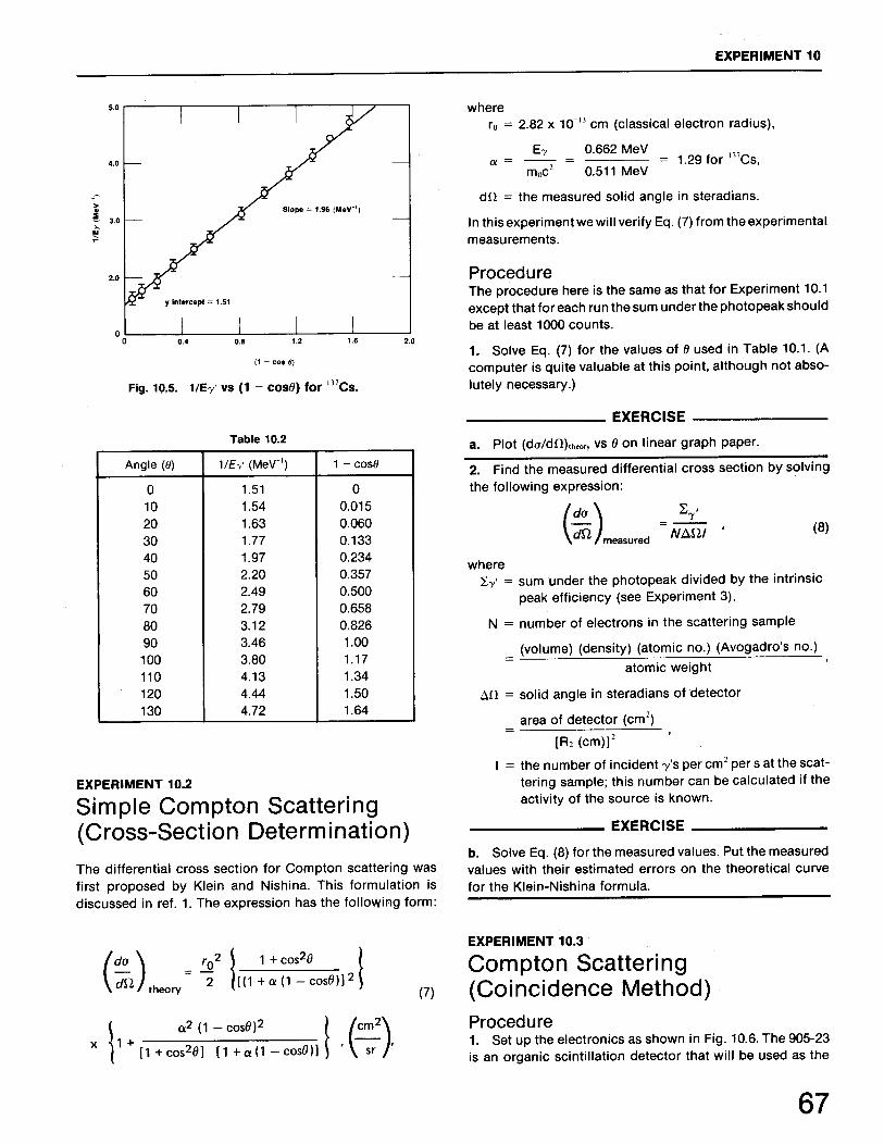
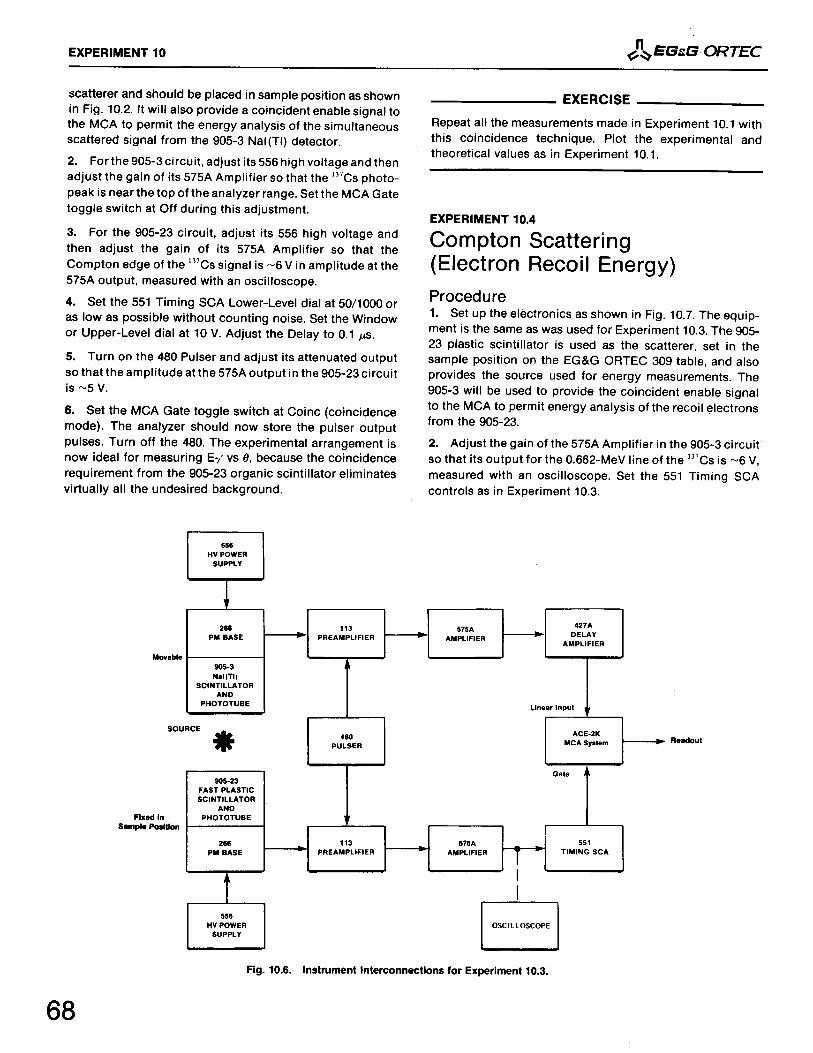
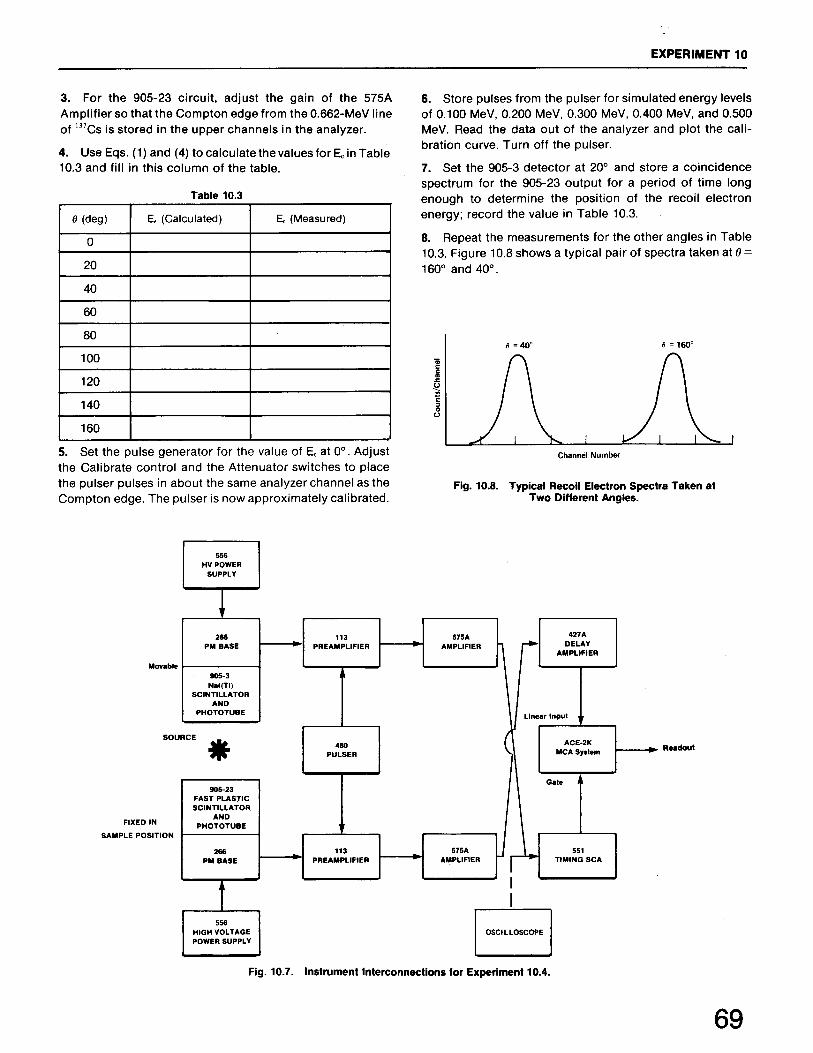
Compton ScatteringSimple Compton Scattering (Energy Determination) Simple Compton Scattering (Cross-Section Determination) Compton Scattering (Coincidence Method) Compton Scattering (Electron Recoil Energy)
Experiment11
11.111.2
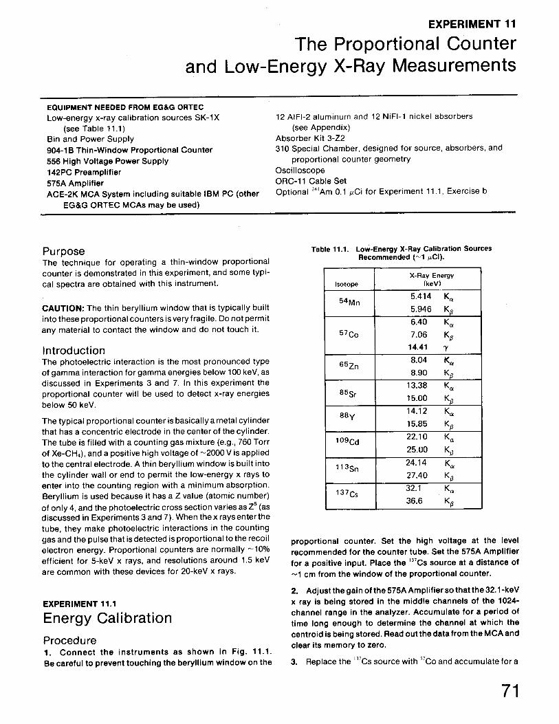
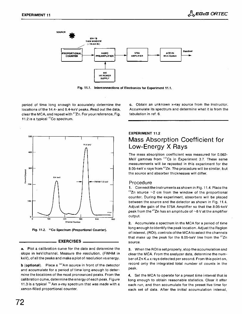
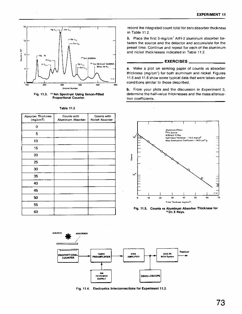
The Proportional Counter and Low-Energy X-Ray MeasurementsEnergy Calibration Mass Absorption Coefficient for Low-Energy X Rays
Experiment12
12.112.2
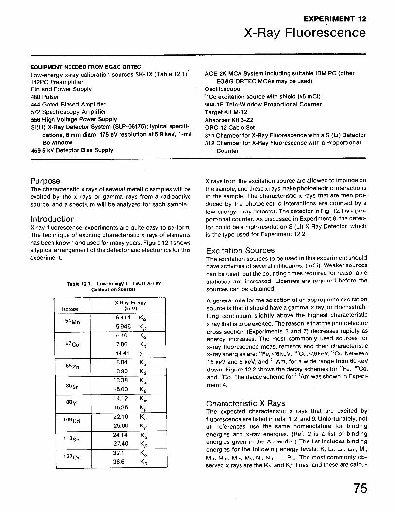
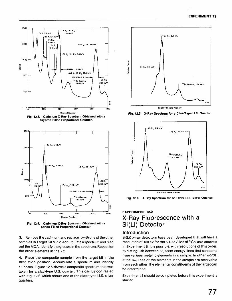
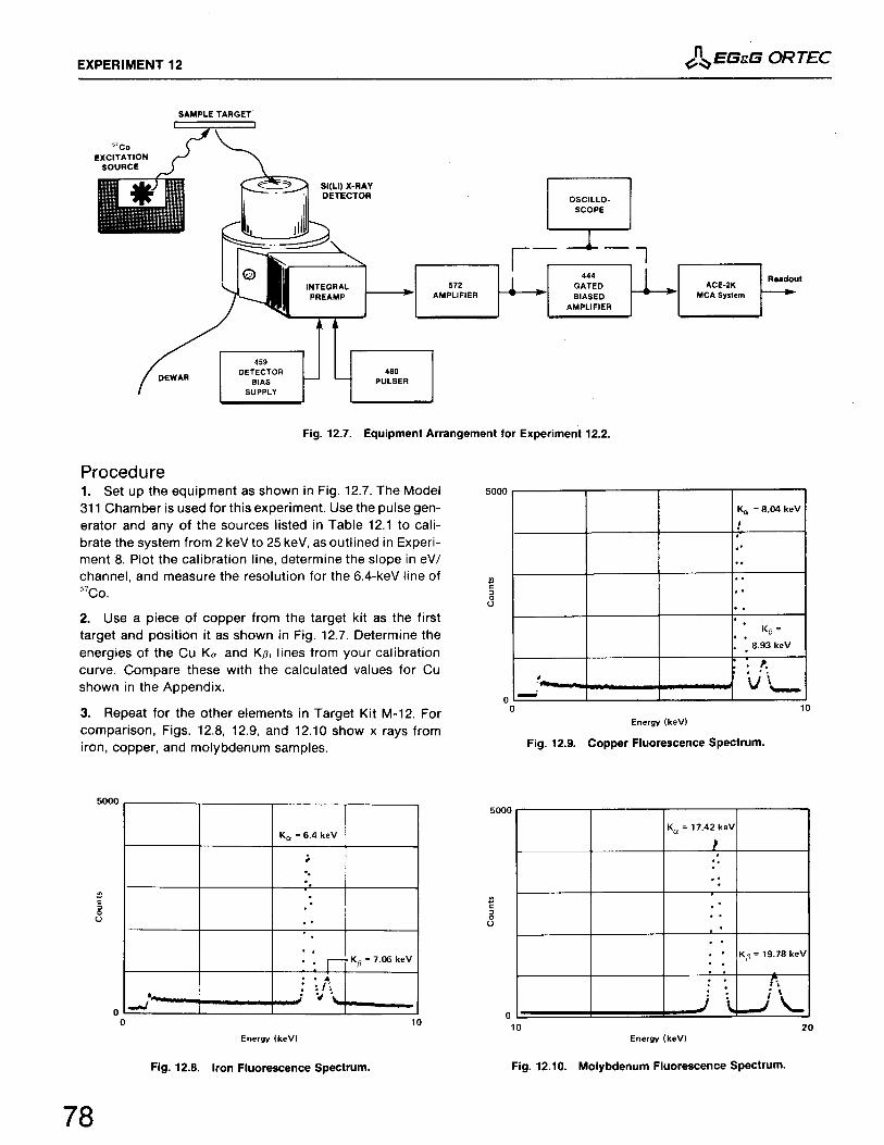
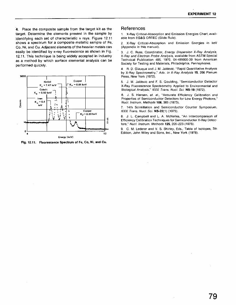
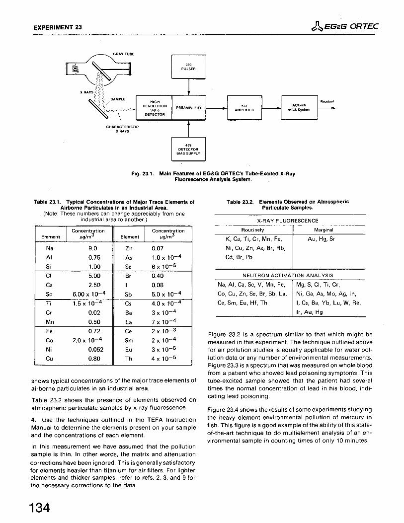
X-Ray FluorescenceX-Ray Fluorescence with a Proportional Counter X-Ray Fluorescence with a Si(Li) Detector
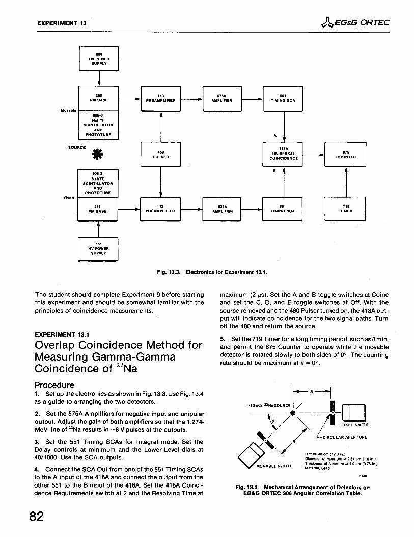
Experiment13
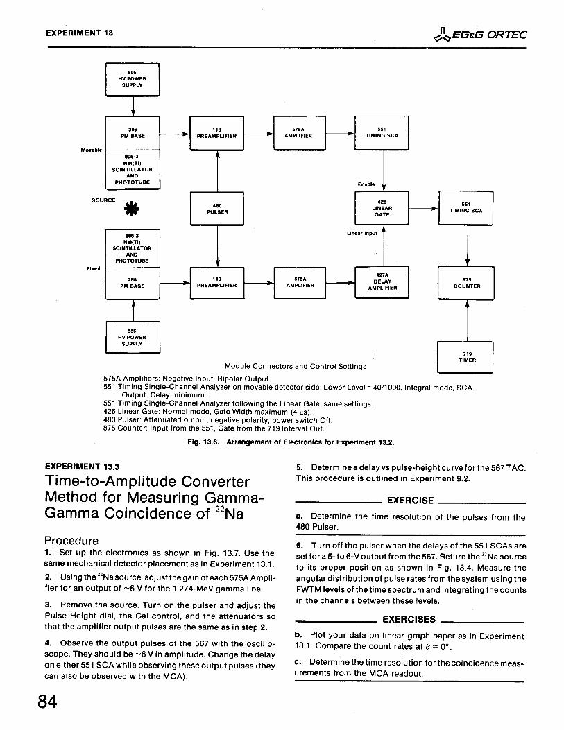
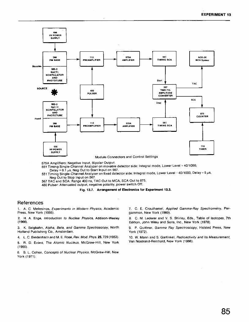
13.113.213.3
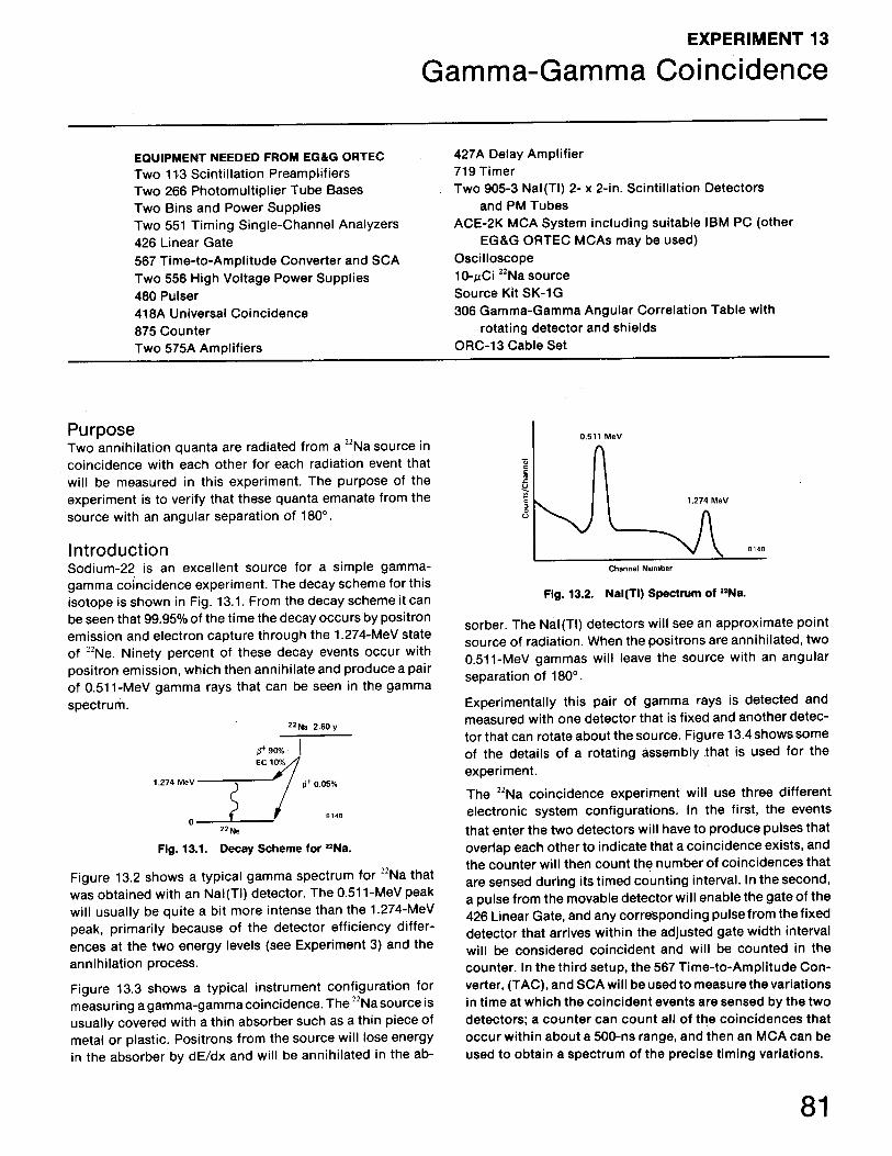
Gamma-Gamma CoincidenceOverlap Coincidence Method for Measuring Gamma-Gamma Coincidence of22Na Linear Gate Method for Measuring Gamma-Gamma Coincidence of 22Na Time-to-Amplitude Converter Method for Measuring Gamma-GammaCoincidence of 22Na
Experiment14
14.114.214.3
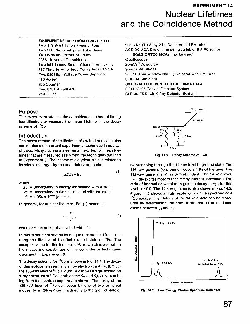
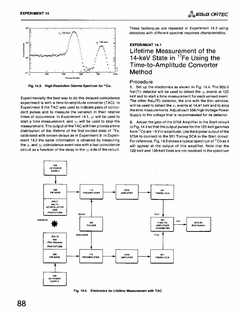
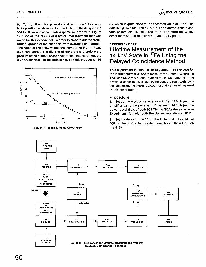
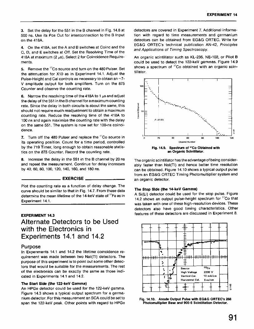
Nuclear Lifetimes and the Coincidence MethodLifetime Measurement of the 14-keV State in 57Fe Using the TAC Method Lifetime Measurement of the 14-keV State in 57Fe Using the DelayedCoincidence Method Alternate Detectors to be Used with the Electronics in Experiments 14.1 and14.2
Experiment15
15.115.2
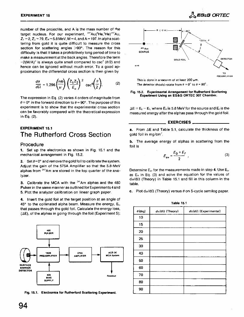
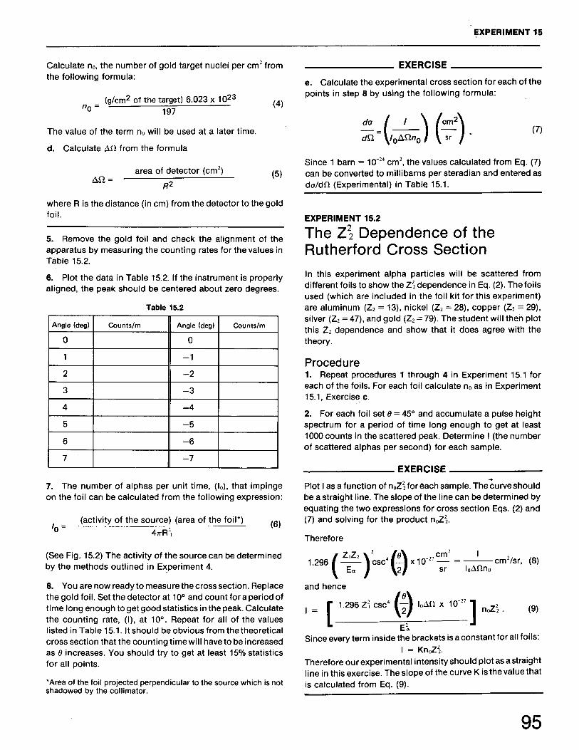
Rutherford Scattering of Alphas from Thin Gold FoilThe Rutherford Cross Section The Z2
2 Dependence of the Rutherford Cross Section
Experiment16
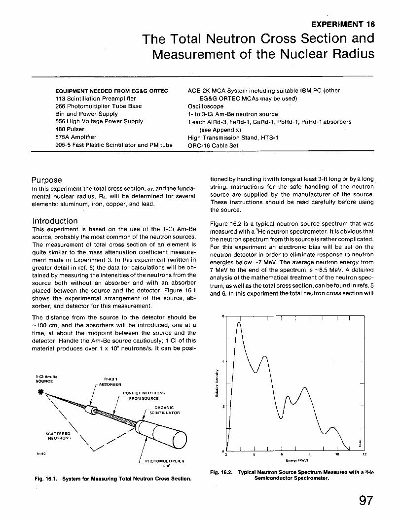
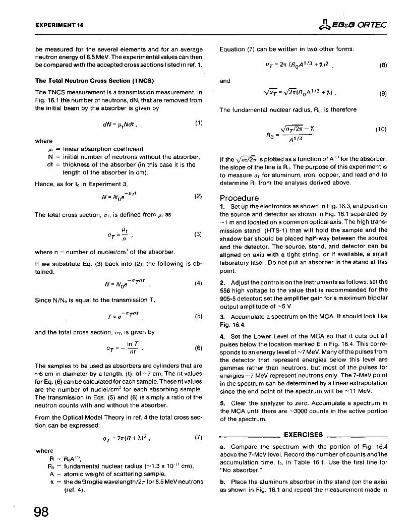
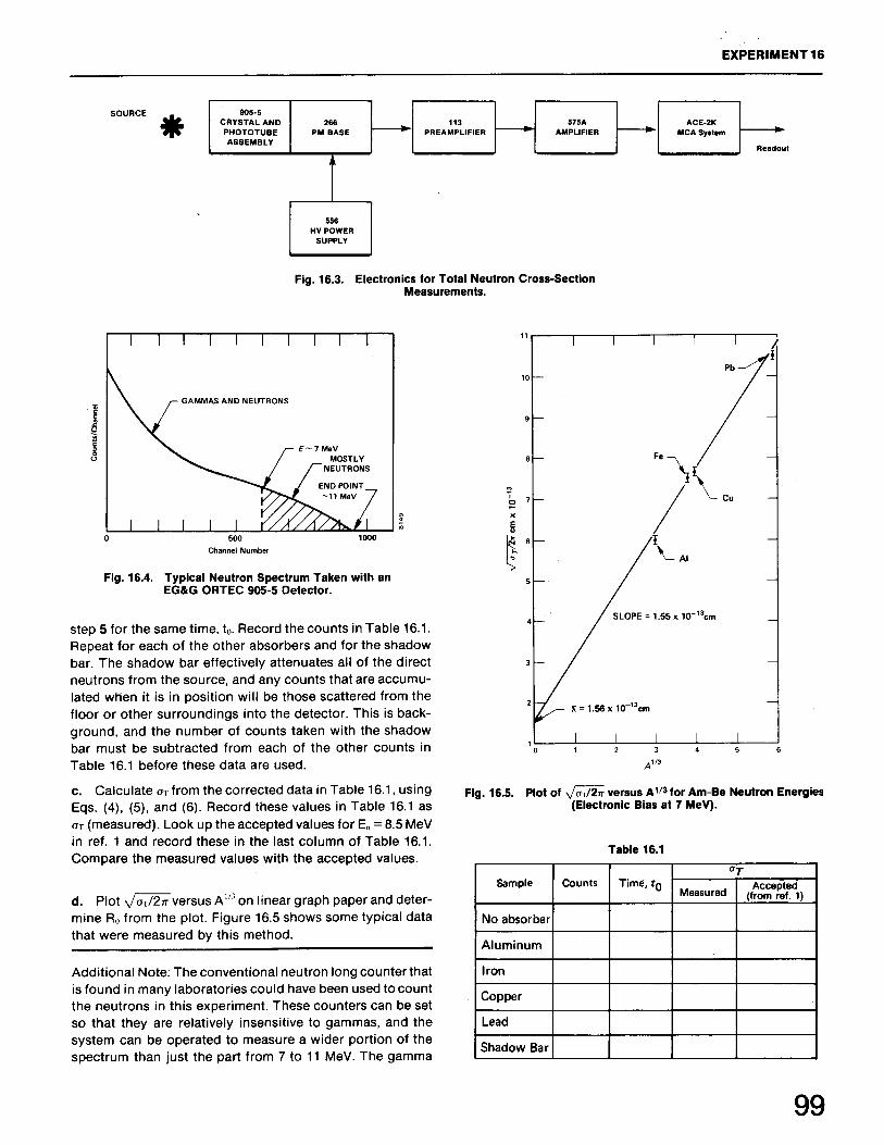
The Total Neutron Cross Section and Measurement of the Nuclear Radius
Experiment17
17.117.217.317.417.517.617.7
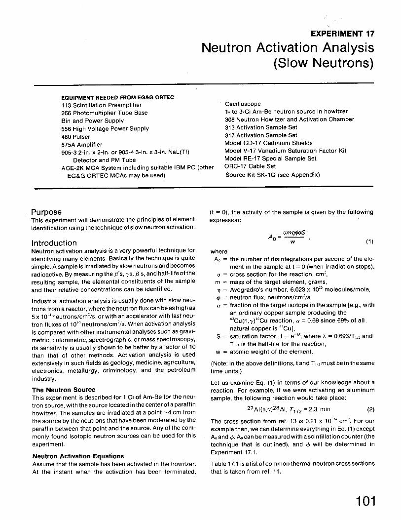
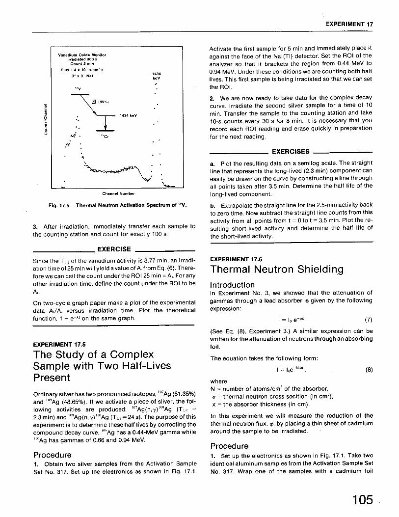
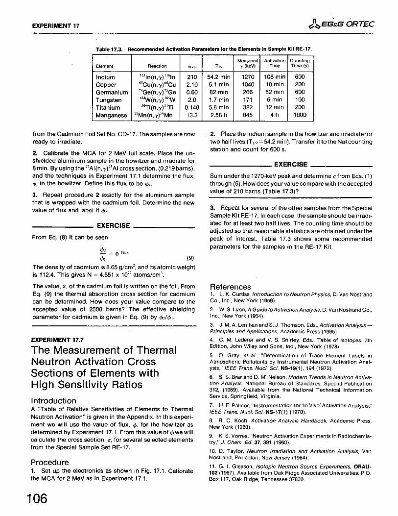
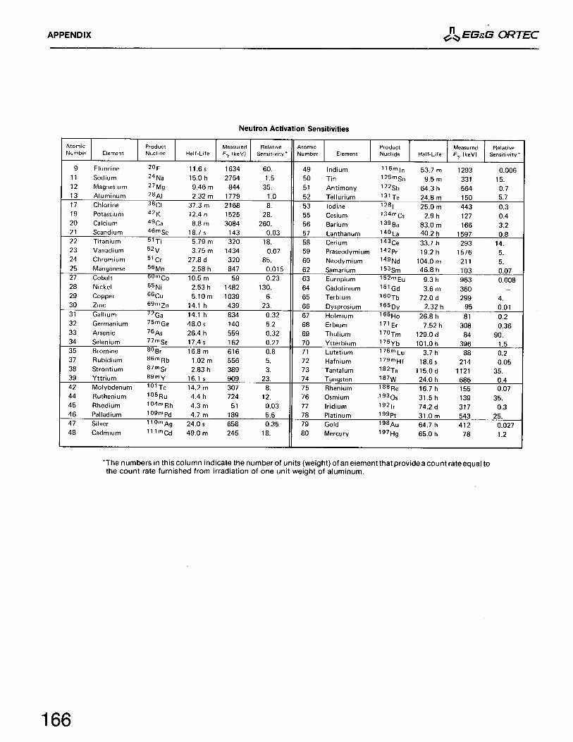
Neutron Activation Analysis (Slow Neutrons)Neutron Flux Determination Measurement of the Thermal Neutron Cross Section for the 51V(n, g) 52VReaction Determination of the Half-Life for the 27Al (n, g) 28Al Reaction The Saturation Factor in Neutron Activation Analysis The Study of a Complex Sample with Two Half-Lives Present Thermal Neutron Shielding The Measurement of Thermal Neutron Activation Cross Sections of Elementswith High Sensitivity Ratios
Experiment18
18.118.2
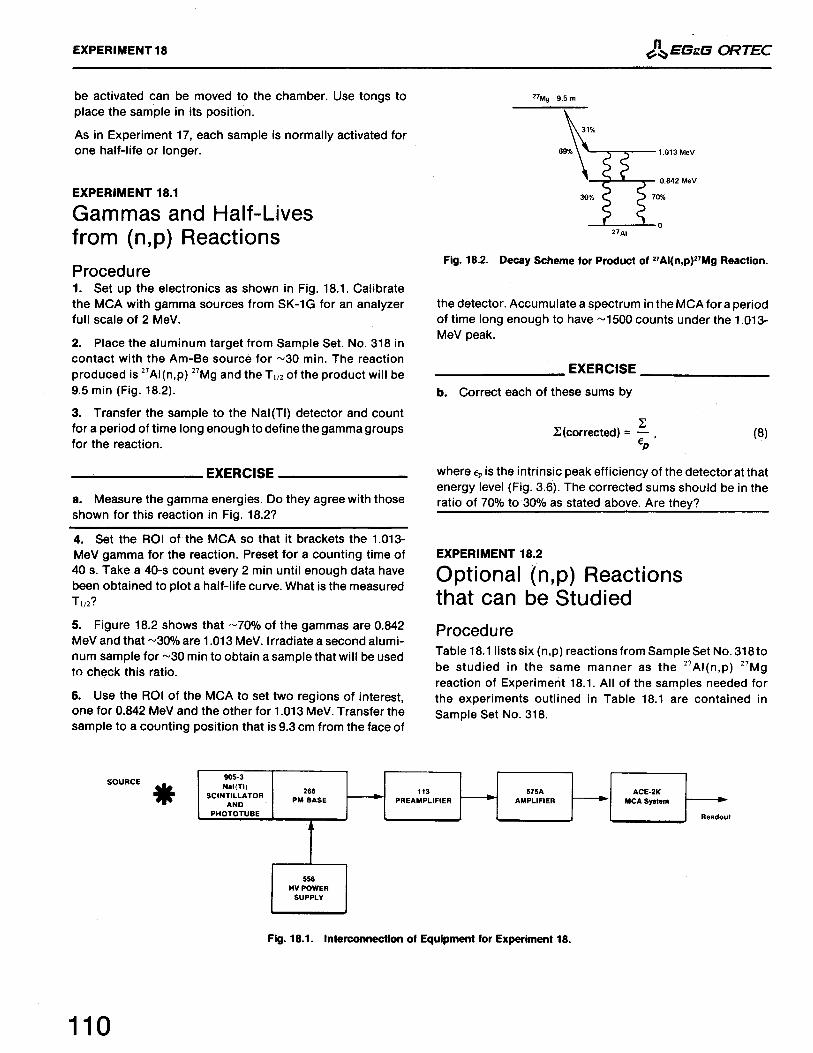
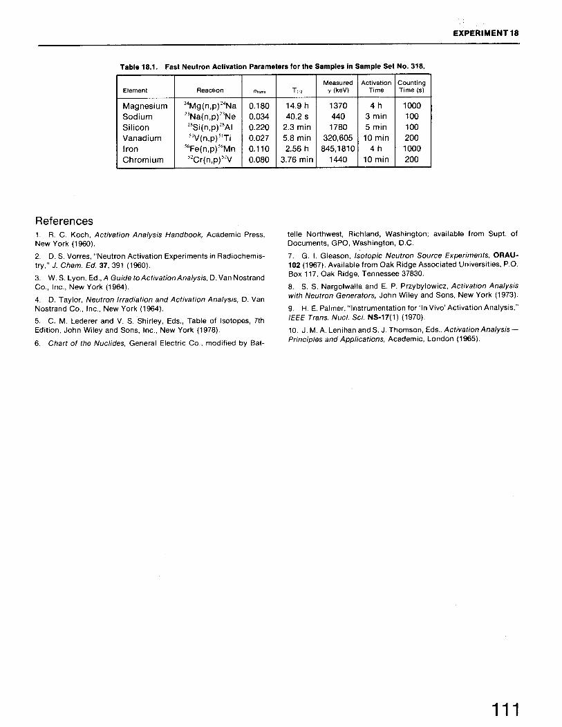
Neutron Activation Analysis (Fast Neutron)Gammas and Half-Lives from (n, p) Reactions Optional (n, p) Reactions that can be Studied
Experiment19
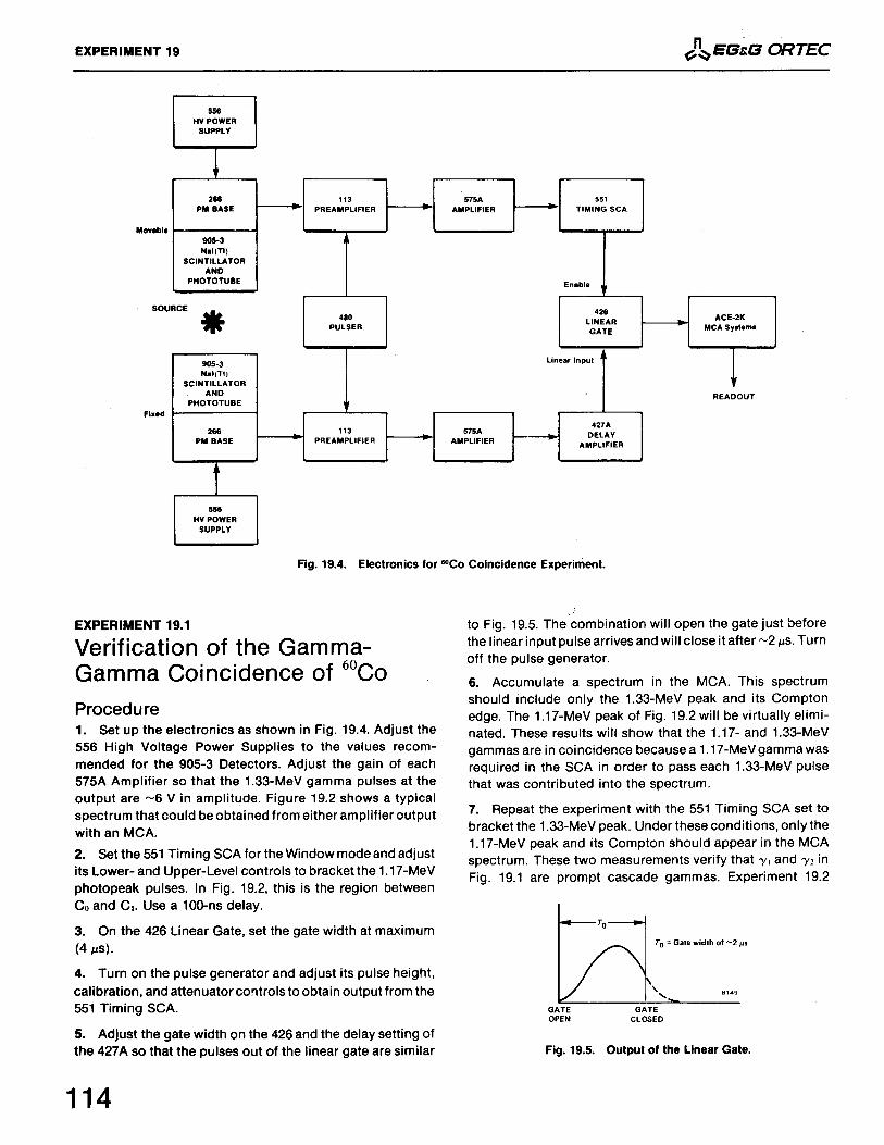
19.119.2
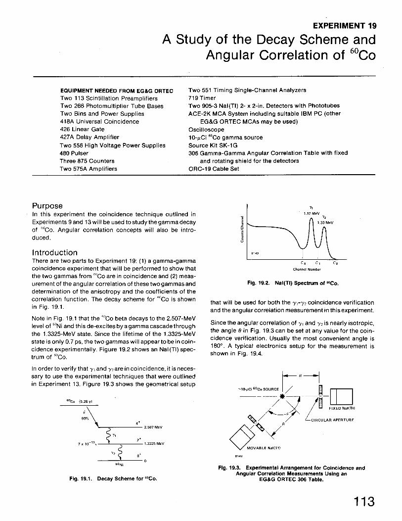
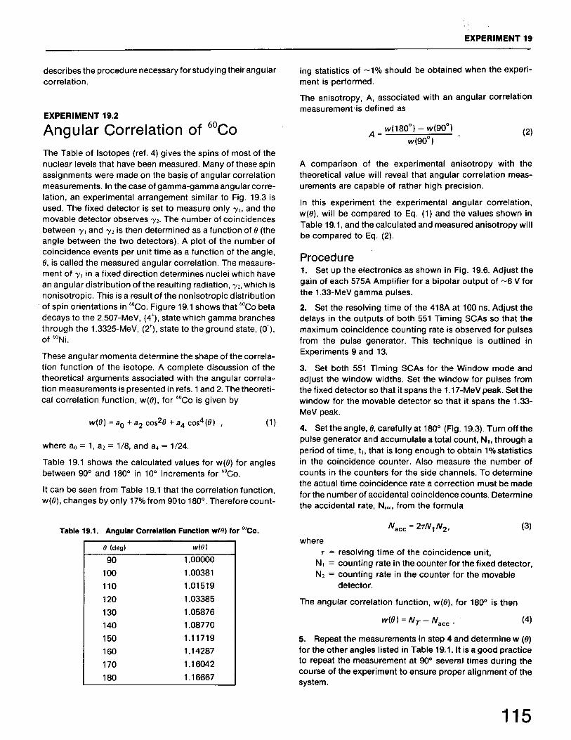
A Study of the Decay Scheme and Angular Correlation of 60CoVerification of the Gamma-Gamma Coincidence of 60Co Angular Correlation of 60Co
Experiment20
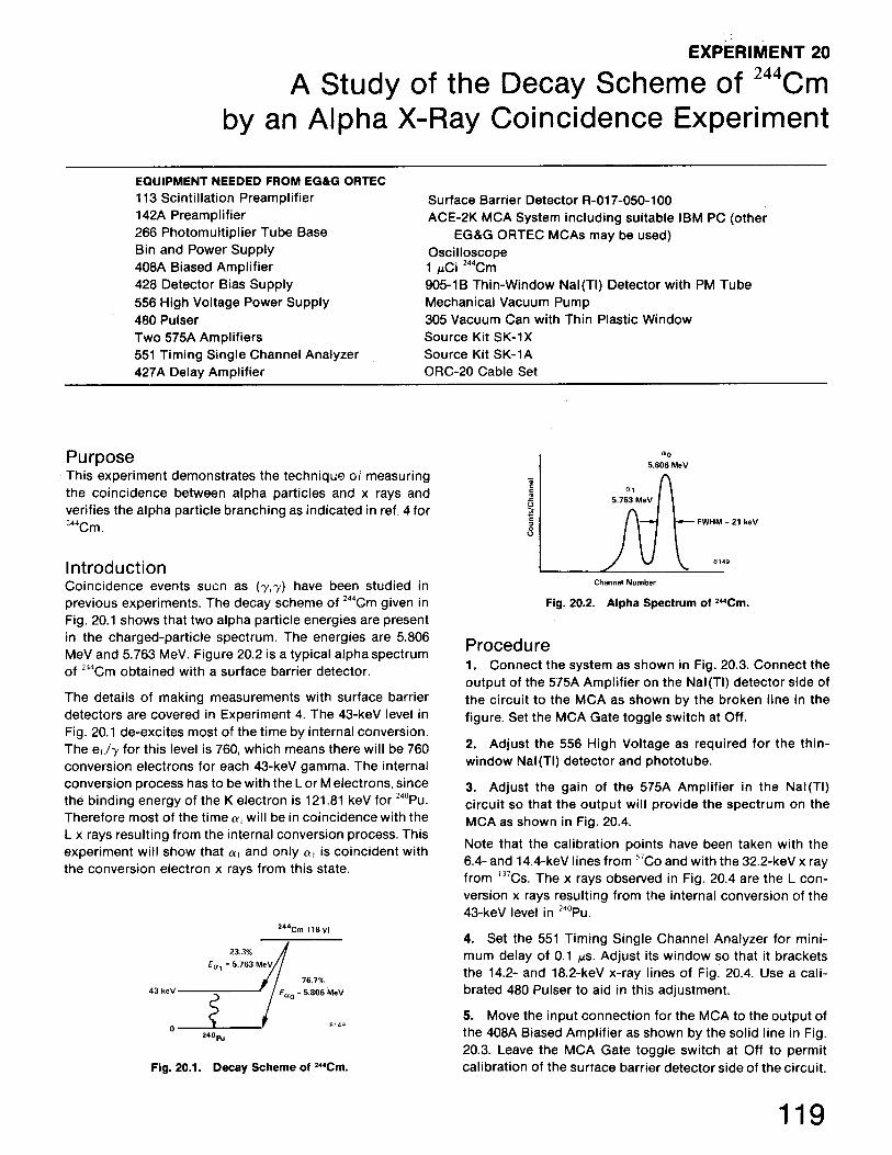
A Study of the Decay Scheme of 244Cm by an Alpha X-Ray CoincidenceExperiment
Experiment21
21.121.221.3
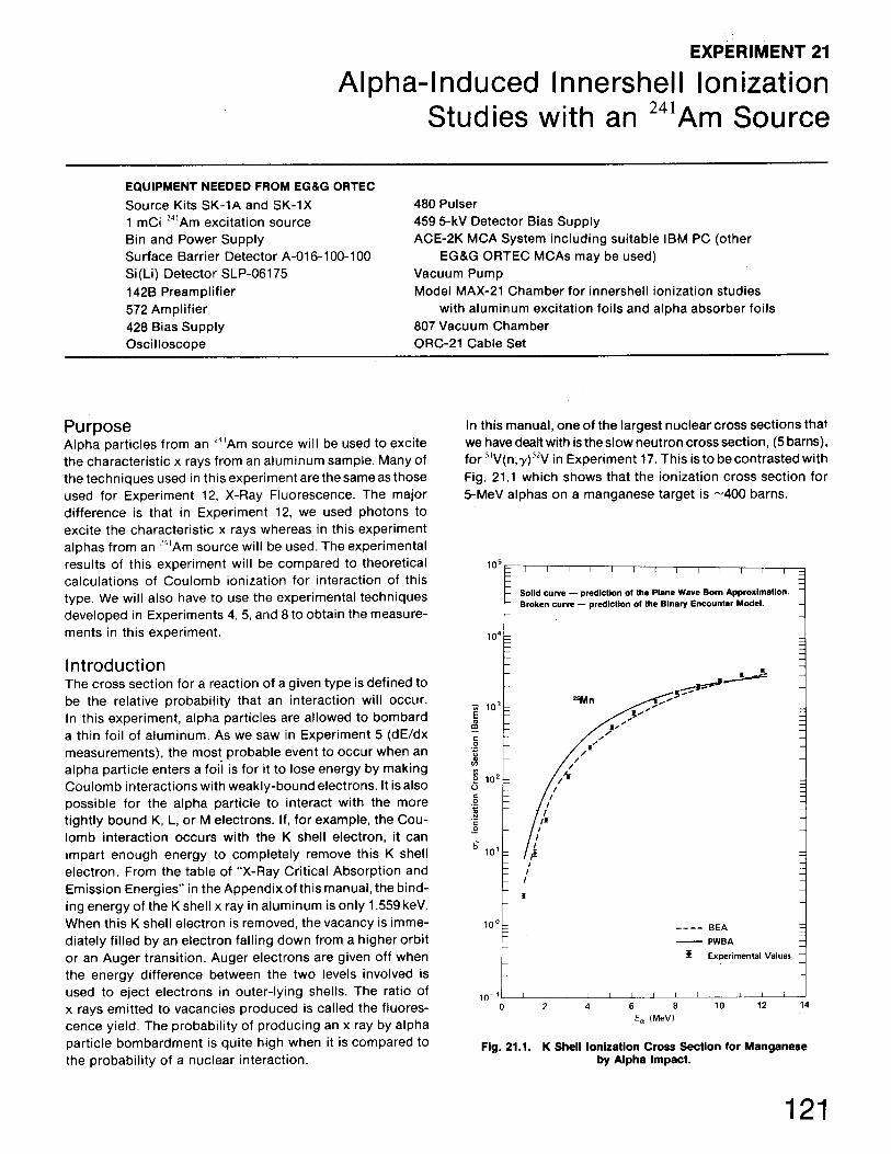
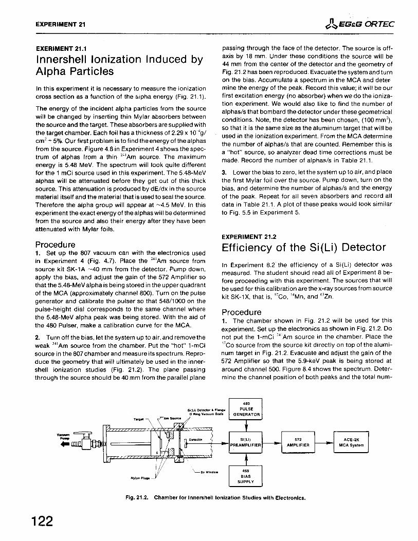
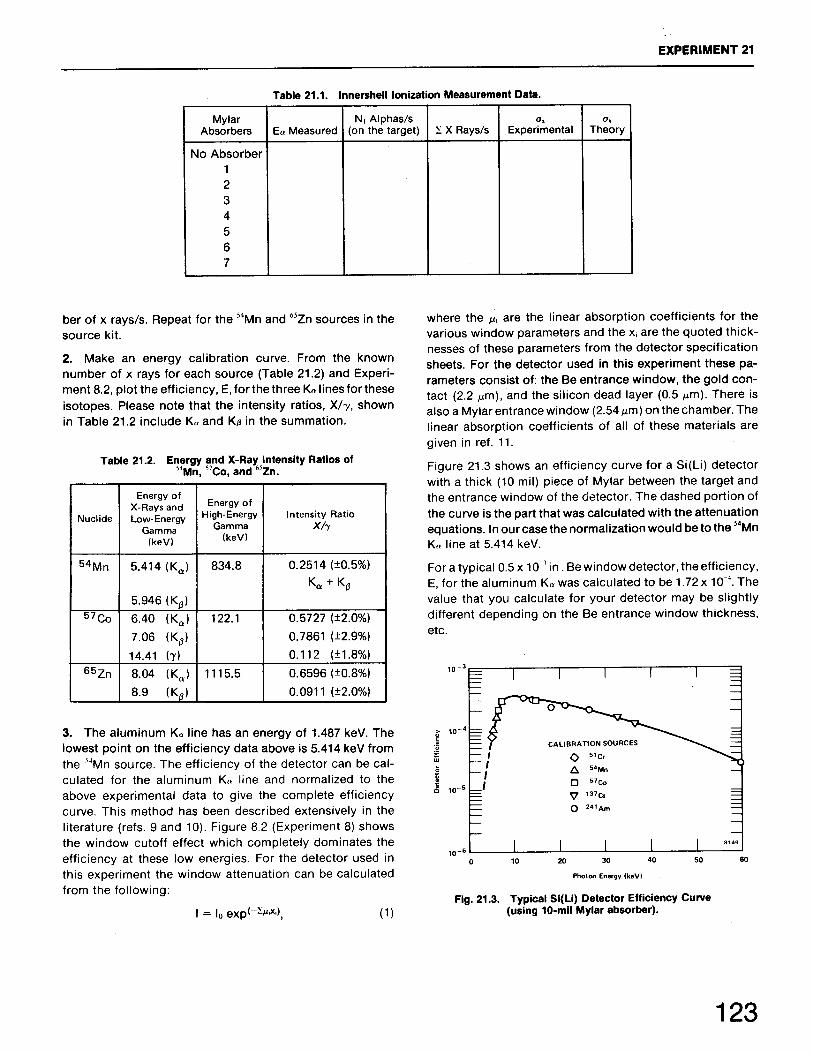
Alpha-Induced Innershell Ionization Studies with an 241Am SourceInnershell Ionization Induced by Alpha Particles Efficiency of the Si(Li) Detector The Innershell Ionization Measurements
Experiment22
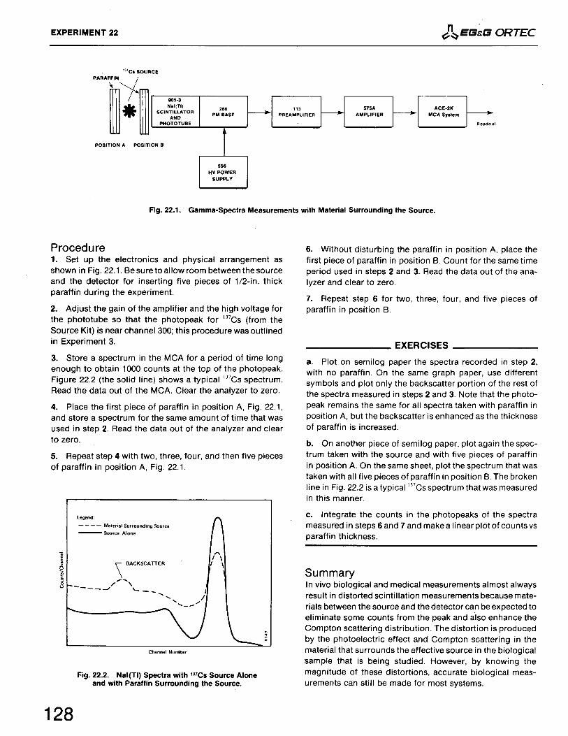
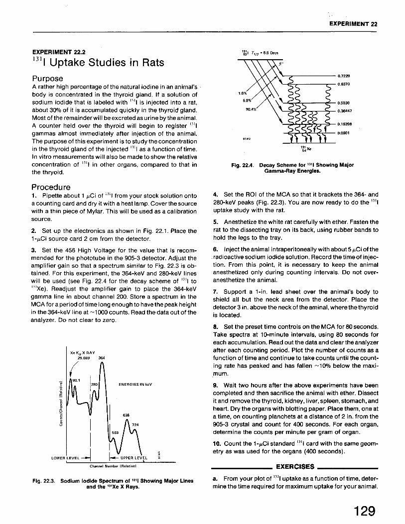
22.122.222.3
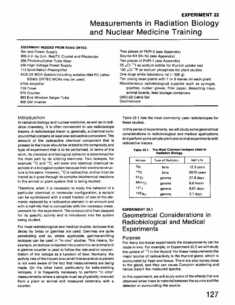
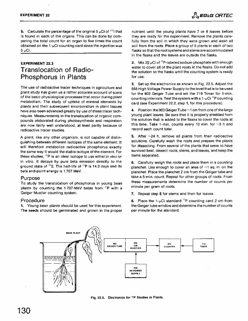
Measurements in Radiation BiologyGeometrical Considerations in Radiobiological and Medical Experiments 131I Uptake Studies in Rats Translocation of Radio-Phosphorus in Plants
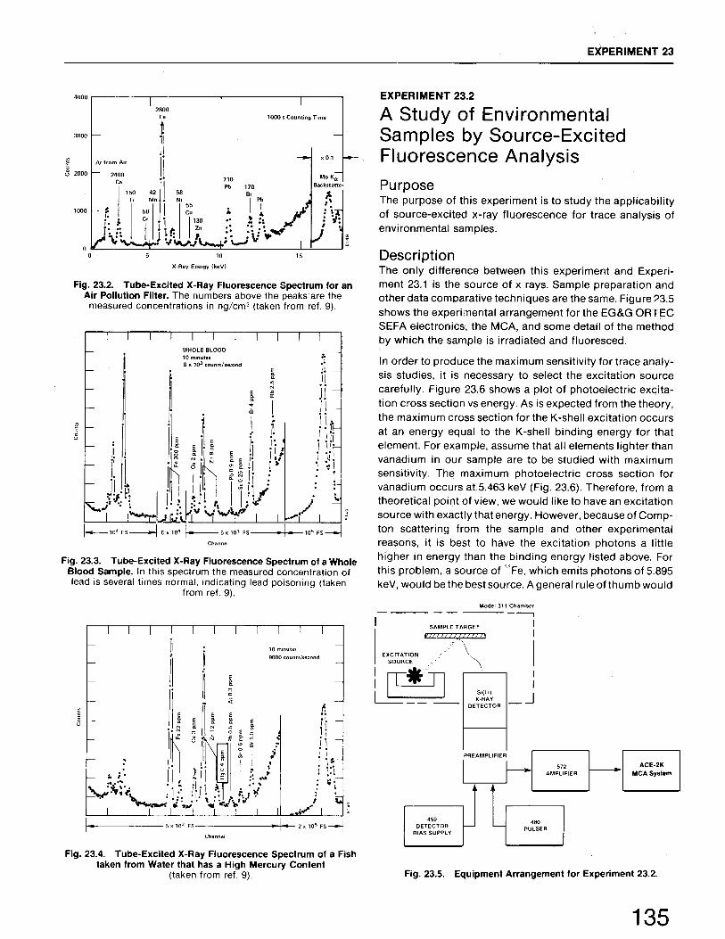
Experiment23
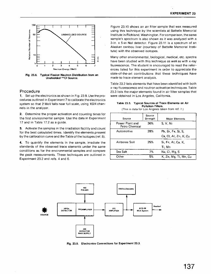
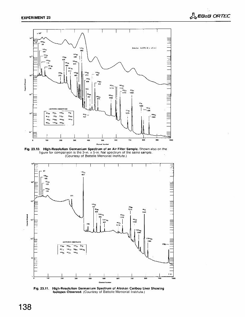
23.123.223.3
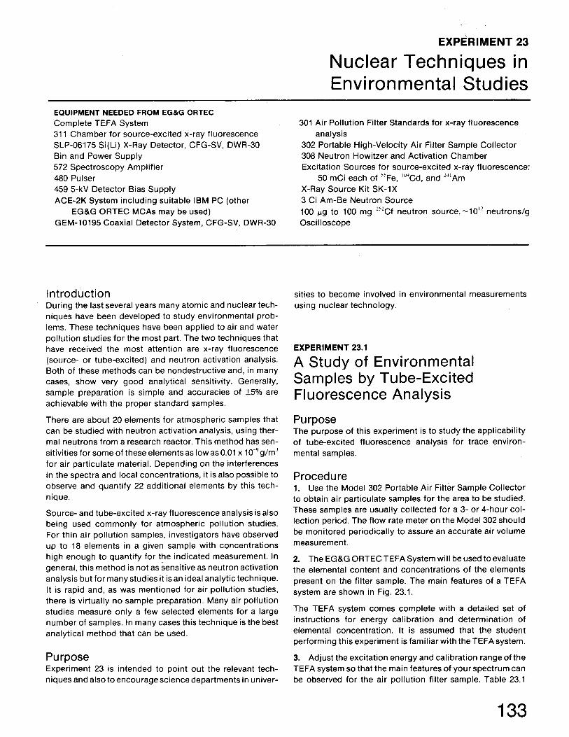
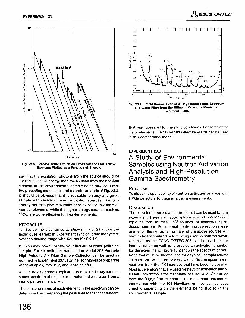
Nuclear Techniques in Environmental StudiesA Study of Environmental Samples by Tube-Excited Fluorescence Analysis A Study of Environmental Samples by Source-Excited Fluroescence Analysis A Study of Environmental Samples Using Neutron Activation Analysis andHigh-Resolution Gamma Spectroscopy

Experiment24
24.124.224.324.424.524.624.7
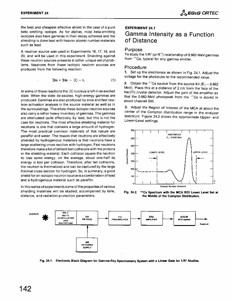
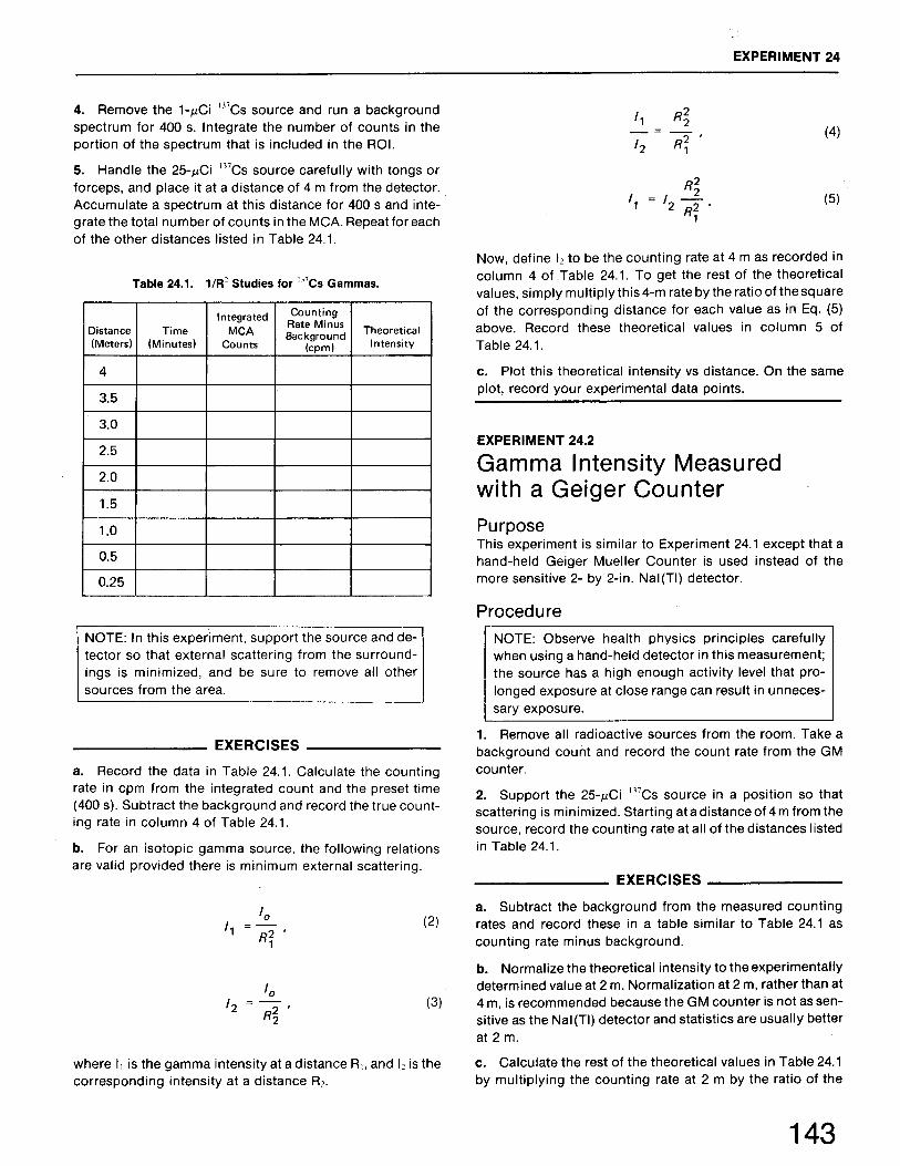
Measurements in Health PhysicsGamma Intensity as a Function of Distance Gamma Intensity Measured with a Geiger Counter Shielding Effectiveness of Different Materials for Gammas Attenuation of Betas in Aluminum by the Geiger Mueller Method Attenuation of Betas in Aluminum by the Surface Barrier Detector Method A Study of Paraffin as a Neutron Shielding Material A Study of Lead as a Neutron Shielding Material
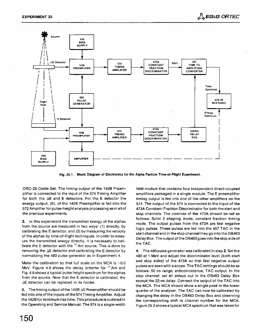
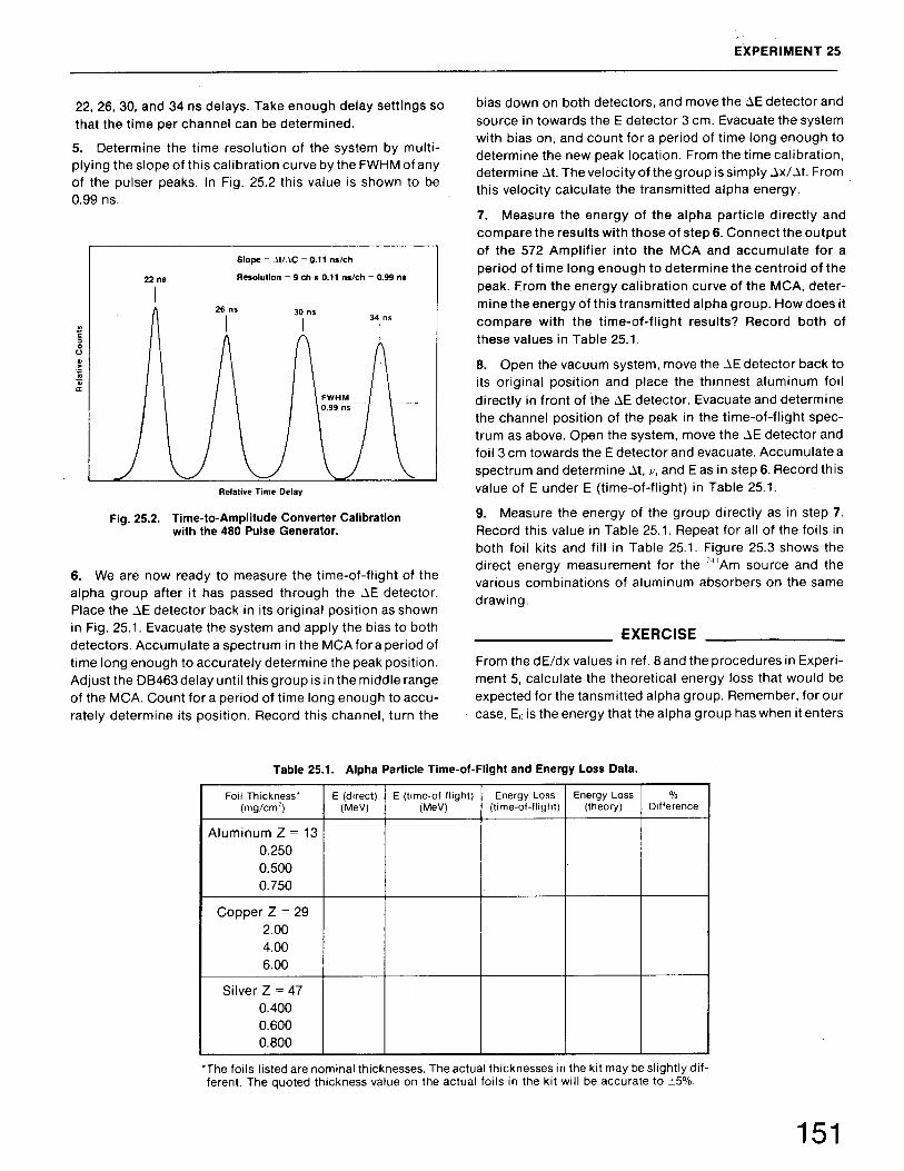
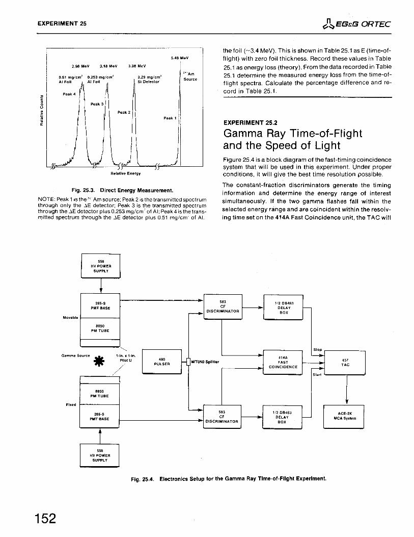
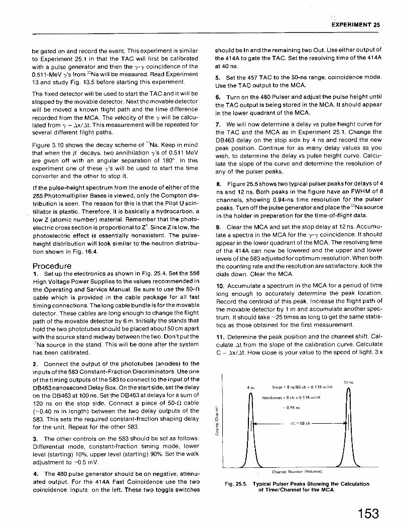
Experiment25
25.125.2
Time-of-Flight SpectroscopyAlpha Particle Time-of-Flight and Energy Loss Measurements Gamma Ray Time-of-Flight and the Speed of Light
Experiment26
26.1
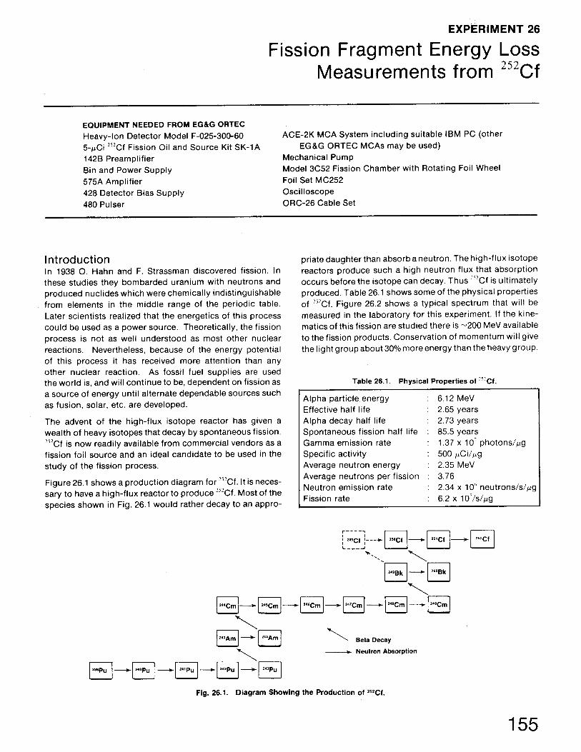
Fission Fragment Energy Loss Measurements from 252CfEnergy Calibration for Fission Fragments
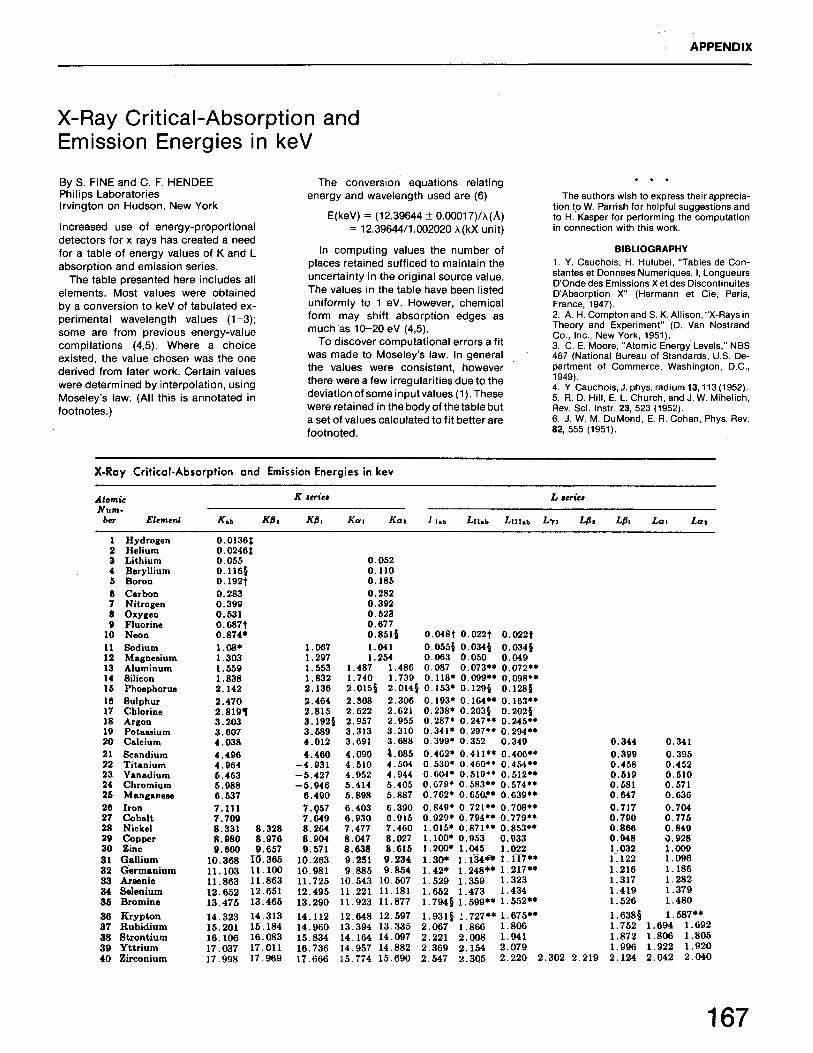
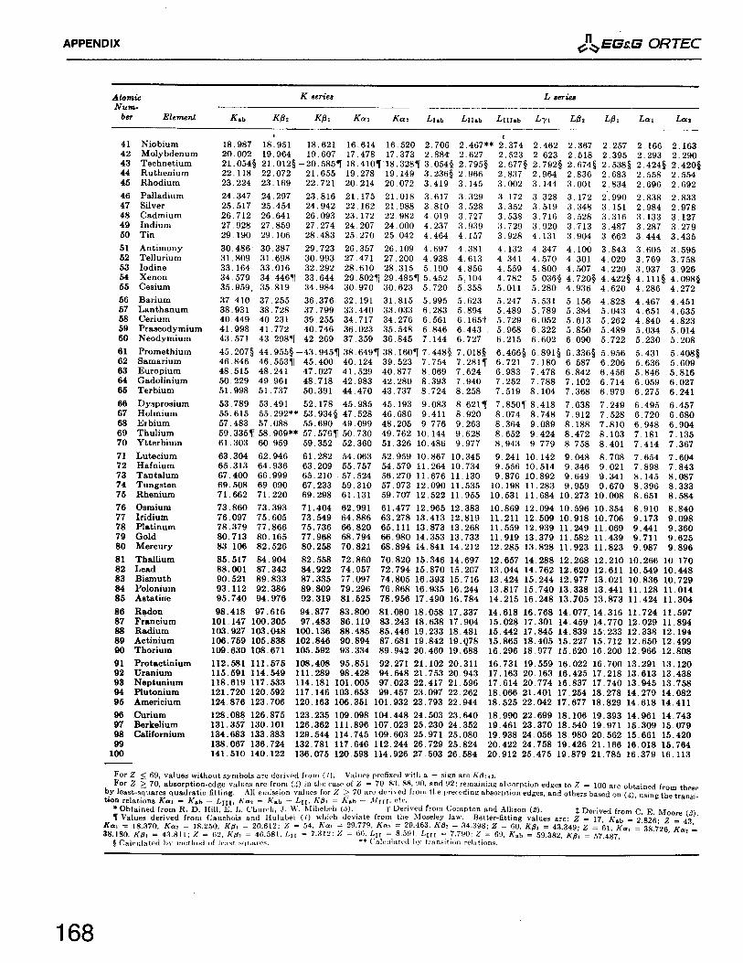
AppendixLinear and Logic Signal Standards in EG&G ORTEC NIM Instruments Equipment and Supplies Identified by Code Glossary Relative Sensitivities of Elements to Thermal Neutron Activation X-Ray Critical-Absorption and Emission Energies in KeV
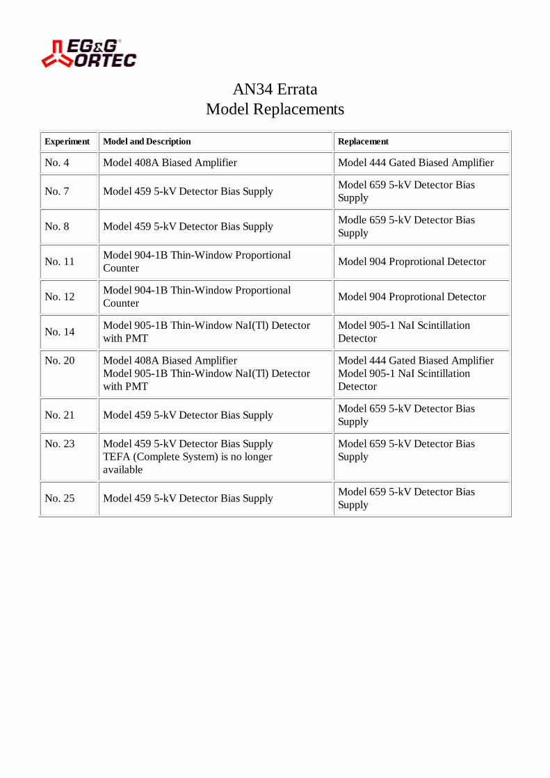
AN34 ErrataModel Replacements
Experiment Model and Description Replacement
No. 4 Model 408A Biased Amplifier Model 444 Gated Biased Amplifier
No. 7 Model 459 5-kV Detector Bias Supply Model 659 5-kV Detector Bias Supply
No. 8 Model 459 5-kV Detector Bias Supply Modle 659 5-kV Detector Bias Supply
No. 11 Model 904-1B Thin-Window Proportional Counter Model 904 Proprotional Detector
No. 12 Model 904-1B Thin-Window Proportional Counter Model 904 Proprotional Detector
No. 14 Model 905-1B Thin-Window NaI(Tl) Detector with PMT
Model 905-1 NaI Scintillation Detector
No. 20 Model 408A Biased AmplifierModel 905-1B Thin-Window NaI(Tl) Detector with PMT
Model 444 Gated Biased AmplifierModel 905-1 NaI Scintillation Detector
No. 21 Model 459 5-kV Detector Bias Supply Model 659 5-kV Detector Bias Supply
No. 23 Model 459 5-kV Detector Bias SupplyTEFA (Complete System) is no longer available
Model 659 5-kV Detector Bias Supply
No. 25 Model 459 5-kV Detector Bias Supply Model 659 5-kV Detector Bias Supply


551Timing Single-Channel Analyzer
2.240
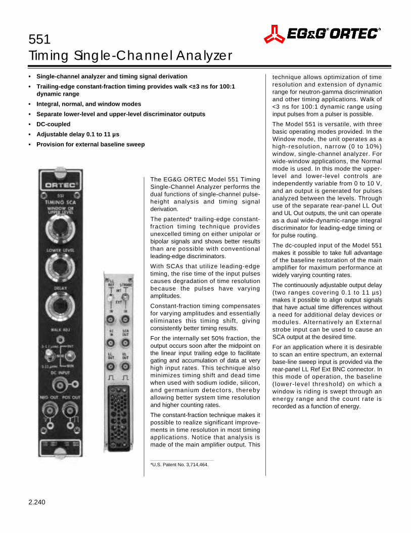
The EG&G ORTEC Model 551 TimingSingle-Channel Analyzer performs thedual functions of single-channel pulse-height analysis and timing signalderivation.
The patented* trailing-edge constant-fraction timing technique providesunexcelled timing on either unipolar orbipolar signals and shows better resultsthan are possible with conventionalleading-edge discriminators.
With SCAs that utilize leading-edgetiming, the rise time of the input pulsescauses degradation of time resolutionbecause the pulses have varyingamplitudes.
Constant-fraction timing compensatesfor varying amplitudes and essentiallyeliminates this timing shift, givingconsistently better timing results.
For the internally set 50% fraction, theoutput occurs soon after the midpoint onthe linear input trailing edge to facilitategating and accumulation of data at veryhigh input rates. This technique alsominimizes timing shift and dead timewhen used with sodium iodide, silicon,and germanium detectors, therebyallowing better system time resolutionand higher counting rates.
The constant-fraction technique makes itpossible to realize significant improve-ments in time resolution in most timingapplications. Notice that analysis ismade of the main amplifier output. This
technique allows optimization of timeresolution and extension of dynamicrange for neutron-gamma discriminationand other timing applications. Walk of< 3 ns for 100:1 dynamic range usinginput pulses from a pulser is possible.
The Model 551 is versatile, with threebasic operating modes provided. In theWindow mode, the unit operates as ahigh-resolut ion, narrow (0 to 10%)window, single-channel analyzer. Forwide-window applications, the Normalmode is used. In this mode the upper-level and lower-level controls areindependently variable from 0 to 10 V,and an output is generated for pulsesanalyzed between the levels. Throughuse of the separate rear-panel LL Outand UL Out outputs, the unit can operateas a dual wide-dynamic-range integraldiscriminator for leading-edge timing orfor pulse routing.
The dc-coupled input of the Model 551makes it possible to take full advantageof the baseline restoration of the mainamplifier for maximum performance atwidely varying counting rates.
The continuously adjustable output delay(two ranges covering 0.1 to 11 µs)makes it possible to align output signalsthat have actual time differences withouta need for additional delay devices ormodules. Alternatively an Externalstrobe input can be used to cause anSCA output at the desired time.
For an application where it is desirableto scan an entire spectrum, an externalbase-line sweep input is provided via therear-panel LL Ref Ext BNC connector. Inthis mode of operation, the baseline( lower- level threshold) on which awindow is riding is swept through anenergy range and the count rate isrecorded as a function of energy.
• Single-channel analyzer and timing signal derivation
• Trailing-edge constant-fraction timing provides walk <±3 ns for 100:1 dynamic range
• Integral, normal, and window modes
• Separate lower-level and upper-level discriminator outputs
• DC-coupled
• Adjustable delay 0.1 to 11 µs
• Provision for external baseline sweep
*U.S. Patent No. 3,714,464.
551Timing Single-Channel Analyzer
2.241
SpecificationsPERFORMANCE
DYNAMIC RANGE 200:1.
PULSE-PAIR RESOLVING TIME O u t p u tpulse width plus Delay (as selected by thefront-panel Delay controls), plus 100 ns forfast NIM output or plus 200 ns for positiveNIM output. Minimum resolving time fornegative output 220 ns; for positive output800 ns.
THRESHOLD TEMPERATUREINSTABILITY ≤±0.01%/°C of full scale, 0 to50°C using a NIM Class A power supply(referenced to –12 V).
DISCRIMINATOR NONLINEARITY ≤±0.25%of full scale (integral) for both discriminators.
DELAY TEMPERATURE INSTABILITY≤±0.03%/°C of full scale, 0 to 50°C.
DELAY NONLINEARITY <±2% of delayrange.
WINDOW WIDTH CONSTANCY ≤ ± 0 . 1 %variation of full-scale window width over thelinear range 0 to 10 V.
MINIMUM INPUT THRESHOLD 50 mV forlower-level discriminator.
TIME SHIFT vs PULSE HEIGHT (WALK)
System A: Using an EG&G ORTEC Model460 Amplif ier, single delay-line mode,integrate ≤0.1 µs with 1-µs delay line.
System B: Using an EG&G ORTEC Model570, 571, or 572 Amplifier, unipolar outputwith 0.5-µs shaping time. Input from EG&GORTEC Model 419 Pulser.
CONTROLSLOWER LEVEL Front-panel 10-turn poten-tiometer adjustable from 0 to 10 V; when therear-panel LL Ref mode switch is set on Int,determines the threshold setting for the lower-level discriminator. When the LL RE F m o d eswitch on the rear panel is in the E X Tposition, this control is ineffective.
WINDOW OR UPPER LEVEL F r o n t - p a n e l10-turn potentiometer determines the windowwidth (0 to +1 V) in the Window mode or theupper-level (0 to +10 V) threshold in theNormal mode. This control is disabled in theIntegral mode.
INT/NOR/WIN Front-panel 3-position lockingtoggle switch selects one of three operatingmodes:Integral LL sets a single-discriminatorthreshold (0 to +10 V) and UL is disabled.Normal UL and LL are independent lyadjustable levels (0 to +10 V).Window LL sets the baseline level (0 to+ 1 0 V) and UL sets the window width (0 to+1 V).
DELAY RANGE Front-panel locking toggleswitch selects delay ranges of 0.1 to 1.1 µs or1.0 to 11 µs.
DELAY Front-panel 10-turn potentiometer forcontinuous adjustment of output delay overselected range. In the external strobe modethe delay control adjusts the automatic resettime from ≈5 µs to 50 µs.
WALK ADJUST Front-panel screwdriveradjustment for precise set t ing of walkcompensation.
LL REF MODE Rear-panel 2-position lockingtoggle switch selects either the front-panel LLpotentiometer or the voltage signal applied tothe rear-panel LL REF EXT connector as theLL discriminator reference threshold.
STROBE Rear-panel 2-position lockingtoggle switch selects ei ther Internal orExternal source for the SCA output signalstrobe function.
INPUTSSIGNAL INPUT Front-panel dc-coupled BNCconnector accepts positive unipolar or bipolars ignal , 0 to +10 V l inear range, ±12 Vmaximum; width 100 ns; 1000- Ω inputimpedance. Rear-panel ac-coupled BNCconnector accepts positive unipolar or bipolarsignal, 0 to +10 V l inear range, ±100 Vmaximum; width 0.2 to 10 µs; 1000-Ω inputimpedance.
LL REF EXT When the rear-panel LL RE Fmode switch is on EX T, the rear-panel LLREF EXT BNC connector accepts the lower-level biasing (an input of 0 to –10 V on thisconnector corresponds to a range of 0 to 10 Vfor the lower-level discriminator setting). Inputprotected to ±24 V.
EXT STROBE I N T When the rear-panelEXT/INT STROBE locking toggle switch is inEX T, the rear-panel EX T STROBE IN B N Cconnector accepts a positive NIM-standardinput, nominally +5 V, 500 ns wide, to causean output to occur from the SCA. The externalstrobe should be given within 5 µs (or 50 µsas determined by the front-panel Delaycontrol) of the linear input. At the end of thisperiod, the Model 551 resets its internal logicwithout producing an output signal.
OUTPUTSSCA POS OUT Front- and rear-panel BNCconnectors provide positive NIM-standardoutput, nominally +5 V; 500 ns wide; 10-Ωoutput impedance. For internal strobe theoutput occurs at the midpoint of the linearinput trailing edge plus the output Delay asselected by the front-panel controls. Forexternal strobe the output occurs at the timeof strobe signal.
SCA NEG OUT Front-panel BNC connectorprovides fast NIM-standard output, nominally–16 mA (–800 mV on 50-Ω load); width≤ 2 0 ns; r ise t ime ≤5 ns; ≤10- Ω outputimpedance. Output occurs at the mid-point ofthe linear trailing edge plus the output Delayas selected by the front-panel controls.
LL OUT Rear-panel BNC connector providespositive NIM-standard output, nominally +5 V,500 ns wide; ≤10-Ω output impedance.Output occurs as leading edge of linear inputcrosses the LL threshold.
UL OUT Rear-panel BNC connector providesNIM-standard output, nominally +5 V, 500 nswide; ≤10-Ω output impedance. Output occursas leading edge of linear input crosses the ULthreshold.
ELECTRICAL AND MECHANICALPOWER REQUIRED +12 V, 160 mA; –12 V,110 mA; +24 V, 90 mA; –24 V, 50mA.
WEIGHTNet 1.1 kg (2.5 lb).Shipping 2.25 kg (5.0 lb).
D I M E N S I O N S NIM-standard single-widthmodule 3.43 X 22.13 cm (1.35 X 8.714 in.)per DOE/ER-0457T.
Related EquipmentThe Model 551 is compatible with all EG&GORTEC amplifiers and other amplifiers havinga 0 to 10 V positive, linear output range.
Ordering Information To order, specify:
Model Description
551 Timing Single-Channel Analyzer
System A
±1.0
±2.5
±3.0
System B
±2.0
±4.0
±8.0
DynamicRange
10:1
50:1
100:1
Walk (ns)
480 Pulser
2.321
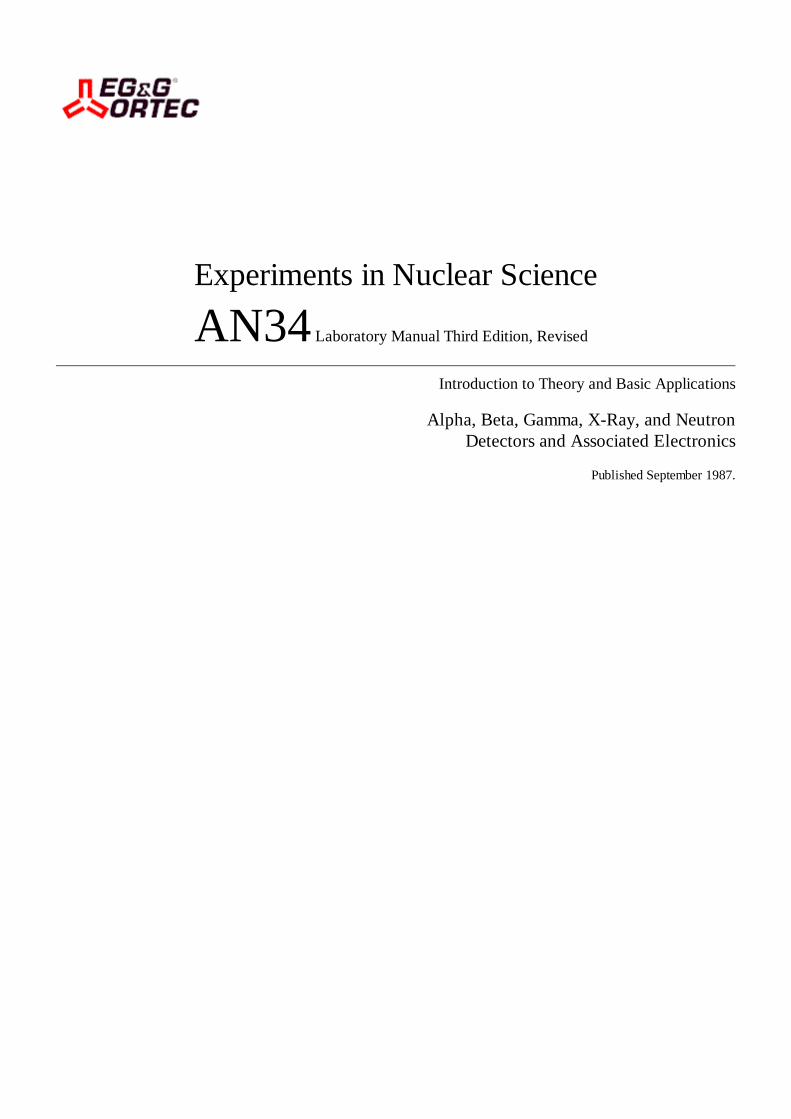
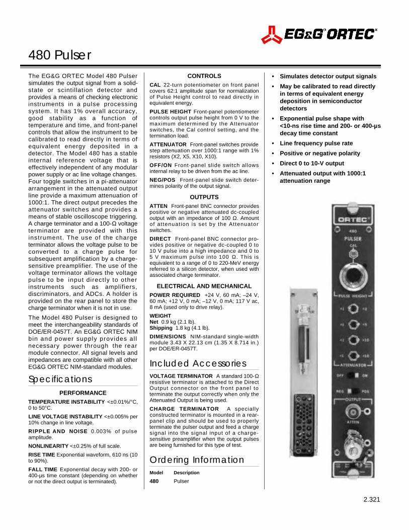
The EG&G ORTEC Model 480 Pulsersimulates the output signal from a solid-state or scinti l lation detector andprovides a means of checking electronicinstruments in a pulse processingsystem. It has 1% overall accuracy,good stability as a function oftemperature and time, and front-panelcontrols that allow the instrument to becalibrated to read directly in terms ofequivalent energy deposited in adetector. The Model 480 has a stableinternal reference voltage that iseffectively independent of any modularpower supply or ac line voltage changes.Four toggle switches in a pi-attenuatorarrangement in the attenuated outputline provide a maximum attenuation of1000:1. The direct output precedes theattenuator switches and provides ameans of stable oscilloscope triggering.A charge terminator and a 100-Ω voltageterminator are provided with thisinstrument. The use of the chargeterminator allows the voltage pulse to beconverted to a charge pulse forsubsequent amplification by a charge-sensitive preamplifier. The use of thevoltage terminator allows the voltagepulse to be input direct ly to otherinstruments such as amplifiers,discriminators, and ADCs. A holder isprovided on the rear panel to store thecharge terminator when it is not in use.
The Model 480 Pulser is designed tomeet the interchangeability standards ofDOE/ER-0457T. An EG&G ORTEC NIMbin and power supply provides al lnecessary power through the rearmodule connector. All signal levels andimpedances are compatible with all otherEG&G ORTEC NIM-standard modules.
SpecificationsPERFORMANCE
TEMPERATURE INSTABILITY < ± 0 . 0 1 % / ° C ,0 to 50°C.
LINE VOLTAGE INSTABILITY <±0.005% per10% change in line voltage.
RIPPLE AND NOISE 0.003% of pulseamplitude.
NONLINEARITY <±0.25% of full scale.
RISE TIME Exponential waveform, 610 ns (10to 90%).
FALL TIME Exponential decay with 200- or400-µs time constant (depending on whetheror not the direct output is terminated).
CONTROLSCAL 22-turn potentiometer on front panelcovers 62:1 amplitude span for normalizationof Pulse Height control to read directly inequivalent energy.
PULSE HEIGHT Front-panel potentiometercontrols output pulse height from 0 V to themaximum determined by the Attenuatorswitches, the Cal control setting, and thetermination load.
ATTENUATOR Front-panel switches providestep attenuation over 1000:1 range with 1%resistors (X2, X5, X10, X10).
O F F / O N Front-panel slide switch allowsinternal relay to be driven from the ac line.
N E G / P O S Front-panel slide switch deter-mines polarity of the output signal.
OUTPUTSATTEN Front-panel BNC connector providespositive or negative attenuated dc-coupledoutput with an impedance of 100 Ω. Amountof at tenuat ion is set by the Attenuatorswitches.
DIRECT Front-panel BNC connector pro-vides positive or negative dc-coupled 0 to1 0 V pulse into a high impedance and 0 to5 V maximum pulse into 100 Ω . This isequivalent to a range of 0 to 220-MeV energyreferred to a silicon detector, when used withassociated charge terminator.
ELECTRICAL AND MECHANICALPOWER REQUIRED +24 V, 60 mA; –24 V,60 mA; +12 V, 0 mA; –12 V, 0 mA; 117 V ac,8 mA (used only to drive relay).
WEIGHT Net 0.9 kg (2.1 lb).Shipping 1.8 kg (4.1 lb).
DIMENSIONS NIM-standard single-widthmodule 3.43 X 22.13 cm (1.35 X 8.714 in.)per DOE/ER-0457T.
Included AccessoriesVOLTAGE TERMINATOR A standard 100-Ωresistive terminator is attached to the DirectOutput connector on the front panel toterminate the output correctly when only theAttenuated Output is being used.
CHARGE TERMINATOR A speciallyconstructed terminator is mounted in a rear-panel clip and should be used to properlyterminate the pulser output and feed a chargesignal into the signal input of a charge-sensitive preamplifier when the output pulsesare being furnished for this type of test.
Ordering InformationModel Description
480 Pulser
• Simulates detector output signals
• May be calibrated to read directly in terms of equivalent energy deposition in semiconductor detectors
• Exponential pulse shape with <10-ns rise time and 200- or 400-µsdecay time constant
• Line frequency pulse rate
• Positive or negative polarity
• Direct 0 to 10-V output
• Attenuated output with 1000:1attenuation range