Embed Size (px)
Citation preview
AN11211 CLRC663 Software Quick start guide Rev. 2.8 — 7 May 2018 226228
Application note COMPANY PUBLIC
Document information Info Content Keywords CLRC663, Blueboard, LPCXpresso, MCU, Code Red, eclipse, LPC1769,
NFC Reader Library, CLEV663B
Abstract This application note is related to the installation procedures of the CLEV6630B Blueboard. It describes the actions to be done to become acquainted with the demo reader.
NXP Semiconductors AN11211 CLRC663 Software Quick start guide
AN11211 All information provided in this document is subject to legal disclaimers. © NXP B.V. 2018. All rights reserved.
Application note COMPANY PUBLIC
Rev. 2.8 — 7 May 2018 226228
2 of 40
Revision history Rev Date Description 2.8 20180507 Editorial updates
2.7 20180117 Descriptive title changed into “CLRC663 Software Quick start guide”, no content change
2.6 20170105 Updated Blueboard CLEV6630B and example descriptions
2.5 20161123 Updated examples descriptions
2.4 20160901 Added LPCXpresso version 8.1.4 requirement Changed note about RTOS option
2.3 20160323 Added description about Ex10 – MIFARE DESFire
2.2 20160125 Added description about LPC11U68 support.
2.1 20151111 Updated all relevant parts in respect to the NFC Reader Library update Removed LPC1227 support
2.0 20150707 Changed chapter 2 based the Blueboard version 3.0. (version 2.1 removed) Changed chapter 4 installation LPCXpresso IDE Added chapter 5.4 ICODE Demo Project Added chapter 7.2 ICODE Software Architecture Chapter 8 – added new links related with ICODE
1.9 20141201 Added a note about RAM limitation of LPC1227
1.8 20140721 Updates in the description regarding the TUSA board.
1.7 20140519 Removed the note about the version of the LPCXpresso IDE. Some small corrections. Changed the description and pictures of the projects Polling and, Classic Changed the description of the P2P description due to a software update. Removed the description about the projects MIFARE Ultralight and MIFARE DESFire. All projects are now based on the NFC Reader Library version 3.010. Therefore all projects have been refactored. Added support for the development board LPCXpresso LPC1769 which is based on an ARM Cortex M3 microcontroller. The NXP Reader Library is now called NFC Reader Library
1.6 20131110 Added a note about the LPCXpresso IDE version in chapter 0
1.5 20130613 Added description about the P2P Snep Client
1.4 20130221 Added description of the P2P project. Added description of the I²C configuration for the Blueboard version 3.0 and above. Added information about the use of the projects in conjunction with the LPC1227 MCU. Added information about the documentation of the NFC Reader Library. Added information about the exemplary project of code size optimization of the NFC Reader Library.
1.3 20120913 Small corrections of the TUSA description
1.2 20120822 Insertion of the description for the 3rd party “Tusa” Board
1.1 20120704 Small text corrections
1.0 20120604 First release
NXP Semiconductors AN11211 CLRC663 Software Quick start guide
AN11211 All information provided in this document is subject to legal disclaimers. © NXP B.V. 2018. All rights reserved.
Application note COMPANY PUBLIC
Rev. 2.8 — 7 May 2018 226228
3 of 40
1. Introduction This application note gives a detailed overview of the hardware for working with the RC663 contactless reader – Blueboard CLEV6630B (Chapter 2) – the installation procedures of the Development Environment (Chapter 3.2) and the handling of the reader projects using the NFC Reader Library (Chapter 3.4).
In this document the term „MIFARE Classic card“ refers to a MIFARE Classic IC-based contactless card, the term “MIFARE DESFire card” refers to a MIFARE DESFire IC-based contactless card, the term “MIFARE Ultralight card” refers to a MIFARE Ultralight IC-based contactless card.
The projects used and explained in this documentation are:
Table 1. Example projects Example projects delivered with the NFC Reader Library Example Description NfcrdlilbEx1_BasicDiscovery Loop
Explains how to poll for different technologies (Tag, P2P, HCE), detect and report them. Default configuration parameters are used.
NfcrdlilbEx2_AdvancedDiscovery Loop
Explains how to poll for different technologies (Tag, P2P, HCE), detect and report them. All configuration parameters are used and explained.
NfcrdlilbEx4_MIFARE Classic Explains the usage of MIFARE Classic card communication commands.
NfcrdlilbEx5_ISO15693 Explains the usage of this technology and provides an overview about the most common commands.
NfcrdlilbEx7_EMVCo_Polling Explains polling for EMVCo payment cards.
NfcrdlilbEx9_NTagI2C Explains NTAG-I2C specific commands.
NfcrdlilbEx10_MIFAREDESFire Explains the usage of MIFARE DESFire cards. (This example is delivered with NXP Reader Library version available via NXP DocStore)
NfcrdlibEx11_ISO10373_PCD Example is used to perform ISO 10373-6 PCD compliance validation.
Nfcrdlib_SimplifiedAPI _EMVCo EMVCo loopback application with simplified API, which can be used for EMVCo level 1 digital certification
Nfcrdlib_SimplifiedAPI _ISO Explains how to use simplified API with different types of cards.
ICODE ILT/SLI Extensively explains the communication with ICODE ILT and ICODE SLI tags. This example is provided in a separate package.
NXP Semiconductors AN11211 CLRC663 Software Quick start guide
AN11211 All information provided in this document is subject to legal disclaimers. © NXP B.V. 2018. All rights reserved.
Application note COMPANY PUBLIC
Rev. 2.8 — 7 May 2018 226228
4 of 40
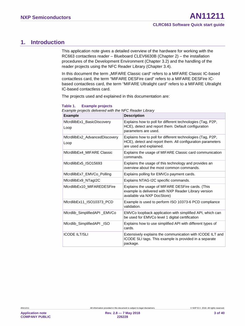
2. Hardware overview of the Demo Board Customer Evaluation Board CLEV6630B demo board is the primary platform for the RC663 reader chip and the current version is Blueboard v2.0. (see Fig 1).
2.1 CLEV6630B demo board (Blueboard)
Fig 1. Picture of RC663 demo board
The CLRC663B V2.0 demo board embeds the contactless communication transceiver IC CLRC66303 with all its elements needed for transmission: EMC filter, matching network and the antenna and LPC1769 MCU with SWD/JTAG interface. The RC66303 supports different kind of contactless communication methods and protocols at 13.56 MHz: • Reader/Writer mode supporting ISO/IEC14443A • Reader/Writer communication mode for MIFARE Classic, • Reader/Writer mode supporting ISO/IEC14443B, • Reader/Writer mode supporting FeliCa scheme, • Passive initiator mode according to NFCIP-1 • Reader/writer supporting ISO/IEC 15693, • Reader/writer supporting ISO/IEC 18000-3 Mode 3, • Refer to the data sheet of this IC [2] for more details
NXP Semiconductors AN11211 CLRC663 Software Quick start guide
AN11211 All information provided in this document is subject to legal disclaimers. © NXP B.V. 2018. All rights reserved.
Application note COMPANY PUBLIC
Rev. 2.8 — 7 May 2018 226228
5 of 40
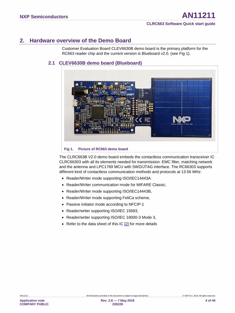
The voltage of the power supply VDD, the pad supply PDD and the transmitter supply can also be configured independently to 3.3 V or 5 V using the jumpers.
Fig 2. Picture of jumper settings
2.2 CE certification of the Blueboard The current version of the Blueboard (CLEV6630B V2.0) is CE (European Conformity) compliant.
NXP Semiconductors AN11211 CLRC663 Software Quick start guide
AN11211 All information provided in this document is subject to legal disclaimers. © NXP B.V. 2018. All rights reserved.
Application note COMPANY PUBLIC
Rev. 2.8 — 7 May 2018 226228
6 of 40
3. Managing the Demo Reader project with LPCXpresso IDE The example reader projects are delivered in a zip package. It can be extracted, edited, compiled and linked with LPCXpresso IDE.
LPCXpresso is a new, low-cost development platform available from NXP. It supports NXP's ARM-based LPC microcontrollers. The platform is comprised of a simplified Eclipse-based IDE and low-cost target boards which include an attached JTAG debugger. This tool can freely be downloaded from the LPCXpresso website [1].
3.1 Development environment To use CLEV6630B prepared software package all components listed in the Table 2 are required.
Table 2. Development Environment Item Version Description
CLEV663B 2.0 Customer Evaluation board (hardware)
LPC-Link 2 1.0 Standalone debug adaptor (hardware)
LPCXpresso IDE 8.1.4 or higher Development IDE (PC software)
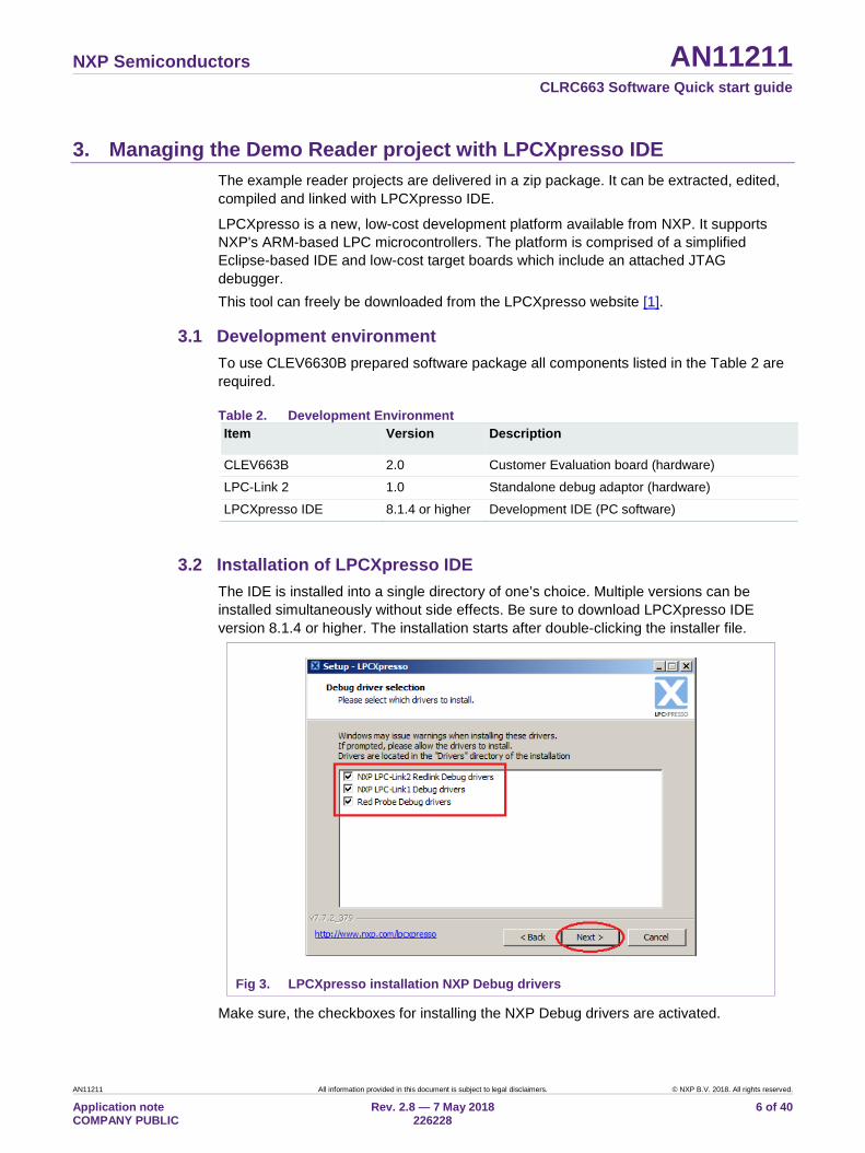
3.2 Installation of LPCXpresso IDE The IDE is installed into a single directory of one’s choice. Multiple versions can be installed simultaneously without side effects. Be sure to download LPCXpresso IDE version 8.1.4 or higher. The installation starts after double-clicking the installer file.
Fig 3. LPCXpresso installation NXP Debug drivers
Make sure, the checkboxes for installing the NXP Debug drivers are activated.
NXP Semiconductors AN11211 CLRC663 Software Quick start guide
AN11211 All information provided in this document is subject to legal disclaimers. © NXP B.V. 2018. All rights reserved.
Application note COMPANY PUBLIC
Rev. 2.8 — 7 May 2018 226228
7 of 40
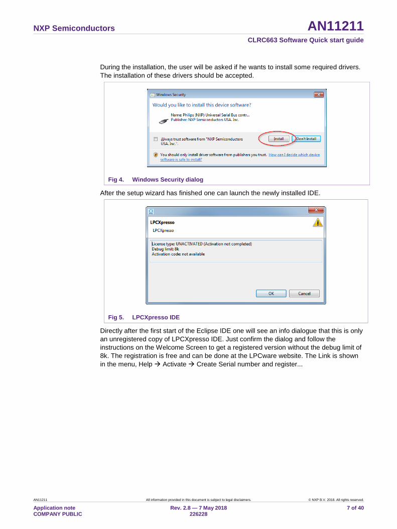
During the installation, the user will be asked if he wants to install some required drivers. The installation of these drivers should be accepted.
Fig 4. Windows Security dialog
After the setup wizard has finished one can launch the newly installed IDE.
Fig 5. LPCXpresso IDE
Directly after the first start of the Eclipse IDE one will see an info dialogue that this is only an unregistered copy of LPCXpresso IDE. Just confirm the dialog and follow the instructions on the Welcome Screen to get a registered version without the debug limit of 8k. The registration is free and can be done at the LPCware website. The Link is shown in the menu, Help Activate Create Serial number and register...
NXP Semiconductors AN11211 CLRC663 Software Quick start guide
AN11211 All information provided in this document is subject to legal disclaimers. © NXP B.V. 2018. All rights reserved.
Application note COMPANY PUBLIC
Rev. 2.8 — 7 May 2018 226228
8 of 40
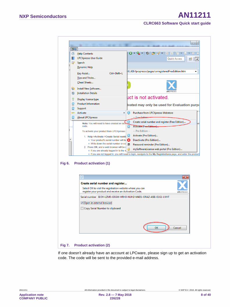
Fig 6. Product activation (1)
Fig 7. Product activation (2)
If one doesn’t already have an account at LPCware, please sign up to get an activation code. The code will be sent to the provided e-mail address.
NXP Semiconductors AN11211 CLRC663 Software Quick start guide
AN11211 All information provided in this document is subject to legal disclaimers. © NXP B.V. 2018. All rights reserved.
Application note COMPANY PUBLIC
Rev. 2.8 — 7 May 2018 226228
9 of 40
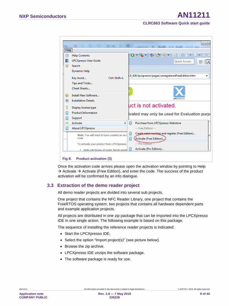
Fig 8. Product activation (3)
Once the activation code arrives please open the activation window by pointing to Help Activate Activate (Free Edition), and enter the code. The success of the product activation will be confirmed by an info dialogue.
3.3 Extraction of the demo reader project All demo reader projects are divided into several sub projects.
One project that contains the NFC Reader Library, one project that contains the FreeRTOS operating system, two projects that contains all hardware dependent parts and example application projects.
All projects are distributed in one zip package that can be imported into the LPCXpresso IDE in one single action. The following example is based on this package.
The sequence of installing the reference reader projects is indicated: • Start the LPCXpresso IDE. • Select the option “Import project(s)” (see picture below). • Browse the zip archive. • LPCXpresso IDE unzips the software package. • The software package is ready for use.
NXP Semiconductors AN11211 CLRC663 Software Quick start guide
AN11211 All information provided in this document is subject to legal disclaimers. © NXP B.V. 2018. All rights reserved.
Application note COMPANY PUBLIC
Rev. 2.8 — 7 May 2018 226228
10 of 40
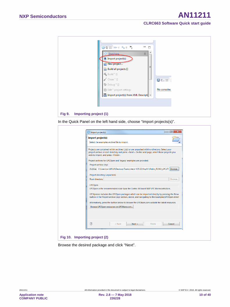
Fig 9. Importing project (1)
In the Quick Panel on the left hand side, choose “Import projects(s)”.
Fig 10. Importing project (2)
Browse the desired package and click “Next”.
NXP Semiconductors AN11211 CLRC663 Software Quick start guide
AN11211 All information provided in this document is subject to legal disclaimers. © NXP B.V. 2018. All rights reserved.
Application note COMPANY PUBLIC
Rev. 2.8 — 7 May 2018 226228
11 of 40
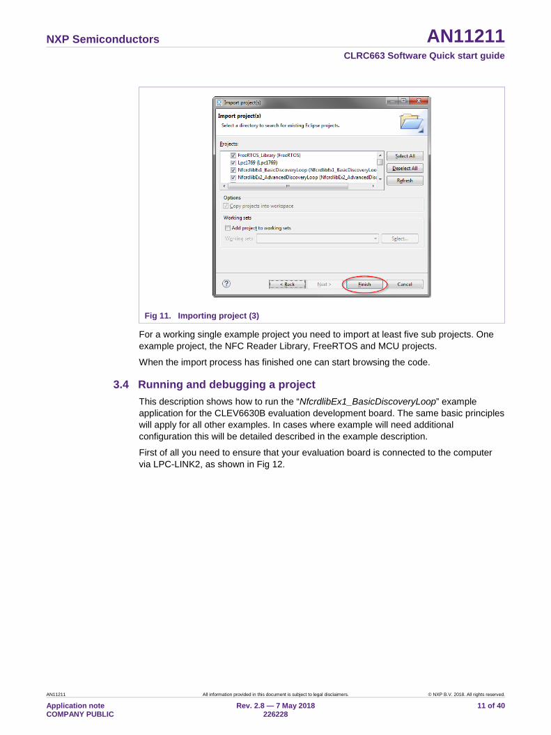
Fig 11. Importing project (3)
For a working single example project you need to import at least five sub projects. One example project, the NFC Reader Library, FreeRTOS and MCU projects.
When the import process has finished one can start browsing the code.
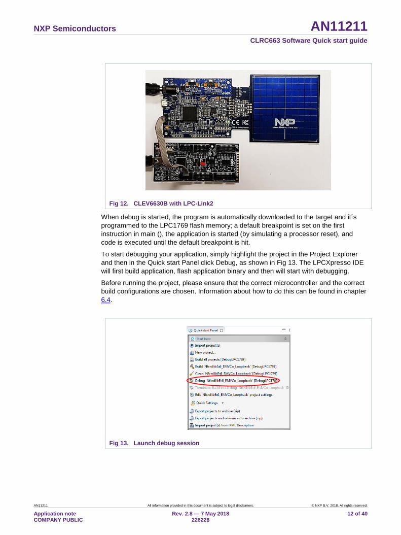
3.4 Running and debugging a project This description shows how to run the “NfcrdlibEx1_BasicDiscoveryLoop” example application for the CLEV6630B evaluation development board. The same basic principles will apply for all other examples. In cases where example will need additional configuration this will be detailed described in the example description.
First of all you need to ensure that your evaluation board is connected to the computer via LPC-LINK2, as shown in Fig 12.
NXP Semiconductors AN11211 CLRC663 Software Quick start guide
AN11211 All information provided in this document is subject to legal disclaimers. © NXP B.V. 2018. All rights reserved.
Application note COMPANY PUBLIC
Rev. 2.8 — 7 May 2018 226228
12 of 40
Fig 12. CLEV6630B with LPC-Link2
When debug is started, the program is automatically downloaded to the target and it´s programmed to the LPC1769 flash memory; a default breakpoint is set on the first instruction in main (), the application is started (by simulating a processor reset), and code is executed until the default breakpoint is hit.
To start debugging your application, simply highlight the project in the Project Explorer and then in the Quick start Panel click Debug, as shown in Fig 13. The LPCXpresso IDE will first build application, flash application binary and then will start with debugging.
Before running the project, please ensure that the correct microcontroller and the correct build configurations are chosen. Information about how to do this can be found in chapter 6.4.
Fig 13. Launch debug session
NXP Semiconductors AN11211 CLRC663 Software Quick start guide
AN11211 All information provided in this document is subject to legal disclaimers. © NXP B.V. 2018. All rights reserved.
Application note COMPANY PUBLIC
Rev. 2.8 — 7 May 2018 226228
13 of 40
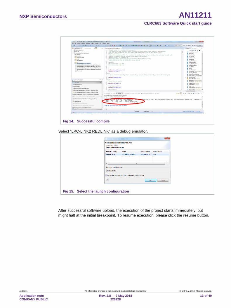
Fig 14. Successful compile Select “LPC-LINK2 REDLINK” as a debug emulator.
Fig 15. Select the launch configuration
After successful software upload, the execution of the project starts immediately, but might halt at the initial breakpoint. To resume execution, please click the resume button.
NXP Semiconductors AN11211 CLRC663 Software Quick start guide
AN11211 All information provided in this document is subject to legal disclaimers. © NXP B.V. 2018. All rights reserved.
Application note COMPANY PUBLIC
Rev. 2.8 — 7 May 2018 226228
14 of 40
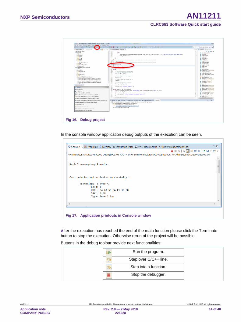
Fig 16. Debug project
In the console window application debug outputs of the execution can be seen.
Fig 17. Application printouts in Console window
After the execution has reached the end of the main function please click the Terminate button to stop the execution. Otherwise rerun of the project will be possible.
Buttons in the debug toolbar provide next functionalities:
Run the program.
Step over C/C++ line.
Step into a function.
Stop the debugger.
NXP Semiconductors AN11211 CLRC663 Software Quick start guide
AN11211 All information provided in this document is subject to legal disclaimers. © NXP B.V. 2018. All rights reserved.
Application note COMPANY PUBLIC
Rev. 2.8 — 7 May 2018 226228
15 of 40
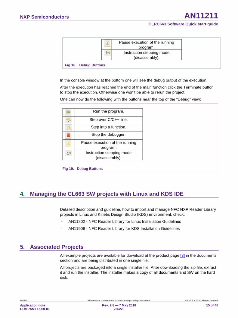
Pause execution of the running
program.
Instruction stepping mode (disassembly).
Fig 18. Debug Buttons
In the console window at the bottom one will see the debug output of the execution.
After the execution has reached the end of the main function click the Terminate button to stop the execution. Otherwise one won’t be able to rerun the project.
One can now do the following with the buttons near the top of the “Debug” view:
Run the program.
Step over C/C++ line.
Step into a function.
Stop the debugger.
Pause execution of the running
program.
Instruction stepping mode (disassembly).
Fig 19. Debug Buttons
4. Managing the CL663 SW projects with Linux and KDS IDE
Detailed description and guideline, how to import and manage NFC NXP Reader Library projects in Linux and Kinetis Design Studio (KDS) environment, check:
- AN11802 - NFC Reader Library for Linux Installation Guidelines
- AN11908 - NFC Reader Library for KDS Installation Guidelines
5. Associated Projects All example projects are available for download at the product page [3] in the documents section and are being distributed in one single file.
All projects are packaged into a single installer file. After downloading the zip file, extract it and run the installer. The installer makes a copy of all documents and SW on the hard disk.
NXP Semiconductors AN11211 CLRC663 Software Quick start guide
AN11211 All information provided in this document is subject to legal disclaimers. © NXP B.V. 2018. All rights reserved.
Application note COMPANY PUBLIC
Rev. 2.8 — 7 May 2018 226228
16 of 40
Running the projects with, or without FreeRTOS
All projects described in the following sub chapters can be configured to run with or without FreeRTOS operating system. To enable/disable FreeRTOS support, define settings in the file “../intfs/ph_NxpBuild_App.h” needs to be configured properly.
E.g. enable FreeRTOS //#define NXPBUILD__PH_OSAL_NULLOS #define NXPBUILD__PH_OSAL_FREERTOS
5.1 Example 1 – Basic Discovery Loop The Discovery Loop can be seen as the entry point when starting to communicate with an NFC tag or device. It scans the close environment for tags and devices of different technologies.
Example is implemented to work in POLL and LISTEN mode of the discovery loop. Information (like UID, SAK, and product type of MIFARE IC) of the detected tags are printed out and it also prints information when it gets activated as a target by an external initiator/reader. Whenever multiple technologies are detected, example select first detected technology and resolve it.
In passive poll mode, Low Power Card Detection (LPCD) is enabled.
NXP Semiconductors AN11211 CLRC663 Software Quick start guide
AN11211 All information provided in this document is subject to legal disclaimers. © NXP B.V. 2018. All rights reserved.
Application note COMPANY PUBLIC
Rev. 2.8 — 7 May 2018 226228
17 of 40
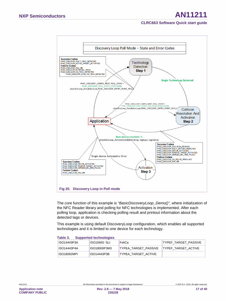
Fig 20. Discovery Loop in Poll mode
The core function of this example is “BasicDiscoveryLoop_Demo()”, where initialization of the NFC Reader library and polling for NFC technologies is implemented. After each polling loop, application is checking polling result and printout information about the detected tags or devices.
This example is using default DiscoveryLoop configuration, which enables all supported technologies and it is limited to one device for each technology.
Table 3. Supported technologies ISO14443P3A ISO15693- SLI FeliCa TYPEF_TARGET_PASSIVE
ISO14443P4A ISO18000P3M3 TYPEA_TARGET_PASSIVE TYPEF_TARGET_ACTIVE
ISO18092MPI ISO14443P3B TYPEA_TARGET_ACTIVE
NXP Semiconductors AN11211 CLRC663 Software Quick start guide
AN11211 All information provided in this document is subject to legal disclaimers. © NXP B.V. 2018. All rights reserved.
Application note COMPANY PUBLIC
Rev. 2.8 — 7 May 2018 226228
18 of 40
5.2 Example 2 – Advanced Discovery Loop Additionally to Example 1 the Advanced Discovery Loop example explains the different configuration options of the Discovery Loop and configure DiscoveryLoop with default values based on the interested profile, NFC or EMVCo.
The configuration of the “DiscoveryLoop” is implemented in "LoadProfile()” function.
5.3 Example 4 – MIFARE Classic card communication This example demonstrates how to configure “DiscoveryLoop” to poll for only one technology and how to resolve detected card, in this example MIFARE Classic is used.
Once MIFARE Classic card is activated, application printout information like UID, ATQA and SAK and perform the authentication with MIFARE Classic card default key. After successful authentication basic read/write operations are implemented.
This example is good start in case of working with only one card or to see how to manage MIFARE Classic cards.
5.4 Example 5 - ISO15693 Similar to the previous example, this one is also using only one technology, in that case ISO15693. “DiscoveryLoop” is configured to resolve only one device and in the example it is shown how to change Tx Guard Time for T5T cards, this is implemented in “phApp_Init()” function.
Once ICODE SLI is resolved and activated, application printout card information like type of the card and UID, and it will read and write from/to the memory block.
This example is good start in case of working with only one card or to see how to manage ISO15693 type of the cards.
5.5 Example 7 – EMVCo Polling The EMVCo Polling example it is demonstrated how to configure NFC Reader Library as specified by EMVCo specifications and starts polling for EMVCo cards.
Once an EMVCo compatible card is resolved and activated, it demonstrates the exchange of APDU commands. This example shall help the developers getting started more quickly when working with EMVCo cards.
5.6 Example 9 – NTAG I2C The NTAG I2C example demonstrates the use of special features which are supported by NTAG I2C. By using POLL mode of the discovery loop, example detect the NTAG I2C cards and displays detected tag information like UID, ATQA, SAK, Version info and perform “Page Read” and “PageWrite” commands.
NXP Semiconductors AN11211 CLRC663 Software Quick start guide
AN11211 All information provided in this document is subject to legal disclaimers. © NXP B.V. 2018. All rights reserved.
Application note COMPANY PUBLIC
Rev. 2.8 — 7 May 2018 226228
19 of 40
For more details about the NTAG-I2C and its functionalities please consult the product page of the same [13].
5.7 Example 10 – MIFARE DESFire card communication The MIFARE DESFire example demonstrates how to use MIFARE DESFire EV1 cards.
Once MIFARE DESFire card is resolved and activated, it displays MIFARE DESFire applications created by this example previously and it displays 32bit signed integer which is incremented after each successful detection of tag.
In case no application is present on the tag, new application will be created with two new files to hold NXPNFCRDLIB version used to create this application and another file to hold 32bit signed integer.
Note: This example including the required modules of the NFC Reader Library is only available via NXP Docstore.
5.8 Example 11 – ISO10373 PCD This example is used to perform ISO 10373-6 PCD compliance validation. This example has to be executed in the DUT which has an ISO 14443 based PCD implementation. The ISO 10373-6 test methods verifies the compliance to the ISO 14443 protocols. An external tool like Micropross MP300 implements the test methods for the ISO 10373-6 and is used as the counterpart for this testing.
5.9 SimplifiedAPI EMVCo This example is similar to the “EMVCo Loopback” example, as it can be used to perform EMVCo 2.5 level 1 digital compliance validation.
The different between both examples is in NFCReaderLibrary initialization, where this example is using simplified reader library initialization process. Simplified approach, after library initialization, is using only three commands:
- phNfcLib_Activate()
- phNfcLib_Transmit()
- phNfcLib_Receive()
5.10 SimplifiedAPI ISO This example is a reference application to demonstrate the usage of Simplified API with ISO profile. Application contains example of Type A Layer 4, Type B Layer 4, ISO/IEC15693 and ISO/IEC180003m3 and MIFARE DESFire card, MIFARE Ultralight card and MIFARE Classic card communication.
Example demonstrates how to use simplified API, which require, after successful library initialization, only three commands:
- phNfcLib_Activate()
- phNfcLib_Transmit()
NXP Semiconductors AN11211 CLRC663 Software Quick start guide
AN11211 All information provided in this document is subject to legal disclaimers. © NXP B.V. 2018. All rights reserved.
Application note COMPANY PUBLIC
Rev. 2.8 — 7 May 2018 226228
20 of 40
- phNfcLib_Receive()
5.11 ICODE Demo Project The ICODE Demo package is a simple embedded software that shows how to perform basic operations with ICODE ILT, ICODE SLI, SLIX and SLIX2 tags. The application interacts with a user through user interface (UI) hosted in the console window of the LPCXpresso IDE. It is designed to get prompts from the user, giving him a possibility to customize the order of execution of commands. It can be downloaded from the documents section of the RC663 demo board page [12].
The package further includes:
• Special version of the NFC Reader Library with content reduced to those modules which are necessary for support of ILT and SLI tags and library dependencies necessary for LPC1769-RC663 platform. The reduced version of the NFC Reader Library is closer described in the chapter 6.2.
• LPC1769 with necessary sources for support of LPC1769 MCU. The LPC1769 MCU has sufficient amount of RAM (64kB) to host the ICODE Demo Project.
The ICODE Demo Project is distributed in a standalone zip file. After downloading and installing, it needs to be imported as a new project into a separate workspace than the previous software packages (MIFARE Classic card communication, P2P communication) because it is not possible to have two different projects with the same name (NFC Reader Library) inside one workspace.
To make the ICODE Demo Project package running follow these steps:
1. Create a new workspace
2. Import the project package zip file into the new created workspace. To do this, follow the instructions from the chapter 3.3
• Running the project Launch Debug configuration of the software (see section 3.4), then it by pressing the resume button. Click with mouse pointer anywhere inside the console window and follow the instructions.
• How to control menu To choose a menu item, press the corresponding key on the keyboard and confirm with ENTER key.
• How to customize the build configuration of the project In the configuration file icode_common.h are three configuration options providing the possibility to build the ICODE Demo project in different configurations to only handle certain type of tags – ILT, SLI without SLIX2, SLI and SLIX2.
Build configuration defines:
o NXPBUILD_SLI_TAG enable SLI tag handling
o NXPBUILD_SLIX_2_TAG enable SLIX2 tag handling
NXP Semiconductors AN11211 CLRC663 Software Quick start guide
AN11211 All information provided in this document is subject to legal disclaimers. © NXP B.V. 2018. All rights reserved.
Application note COMPANY PUBLIC
Rev. 2.8 — 7 May 2018 226228
21 of 40
o NXPBUILD_ILT_TAG enable ILT tag handling Note: SLI is necessary prerequisite for SLIX2 – project cannot be configured only for SLIX2.
To apply a particular build configuration, comment unwanted build configurations, compile and run the project.
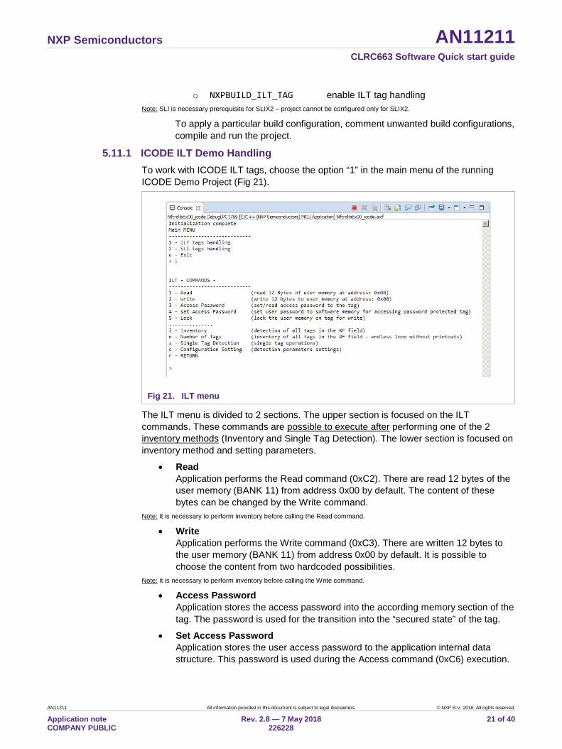
5.11.1 ICODE ILT Demo Handling To work with ICODE ILT tags, choose the option “1” in the main menu of the running ICODE Demo Project (Fig 21).
Fig 21. ILT menu
The ILT menu is divided to 2 sections. The upper section is focused on the ILT commands. These commands are possible to execute after performing one of the 2 inventory methods (Inventory and Single Tag Detection). The lower section is focused on inventory method and setting parameters.
• Read Application performs the Read command (0xC2). There are read 12 bytes of the user memory (BANK 11) from address 0x00 by default. The content of these bytes can be changed by the Write command.
Note: It is necessary to perform inventory before calling the Read command.
• Write Application performs the Write command (0xC3). There are written 12 bytes to the user memory (BANK 11) from address 0x00 by default. It is possible to choose the content from two hardcoded possibilities.
Note: It is necessary to perform inventory before calling the Write command.
• Access Password Application stores the access password into the according memory section of the tag. The password is used for the transition into the “secured state” of the tag.
• Set Access Password Application stores the user access password to the application internal data structure. This password is used during the Access command (0xC6) execution.
NXP Semiconductors AN11211 CLRC663 Software Quick start guide
AN11211 All information provided in this document is subject to legal disclaimers. © NXP B.V. 2018. All rights reserved.
Application note COMPANY PUBLIC
Rev. 2.8 — 7 May 2018 226228
22 of 40
This helps to demonstrate the use-case when the user password doesn’t fit the access password stored in the tag and the secure operations on the tag are not allowed.
• Lock Application locks and unlocks the user memory (BANK 11) for writing. Write is possible only if the locked tag is in “secured state”. Transition of the tag from “open state” to “secured state” need to be accomplished by using the Access command.
Note 1: All commands of the tag (read, write, lock … etc.) are performed like commands sequence to transition the tag’s state from Ready, Arbitrate or Reply state to Open or Secured state (see the specification [8]). Within this sequence it is conditional calling the Access command. The condition if command is called or not is possible to set via the Access Password menu or via the Configuration setting.
Note 2: In case verification of memory lock is needed, you can perform the following command sequence: “set Access Password” - 0x12345678, “Set Password” - 0x12345678, “Set Password” - set the usage the an access password to ON state, “Lock” - lock the user memory for writing, “Write” – something from menu - writing is possible, “Lock” - un-lock the user memory for writing, “Write” – something from menu -> write is not possible, because memory is locked without access.
Note 3: Parameter of Access command calling is set by default to state OFF.
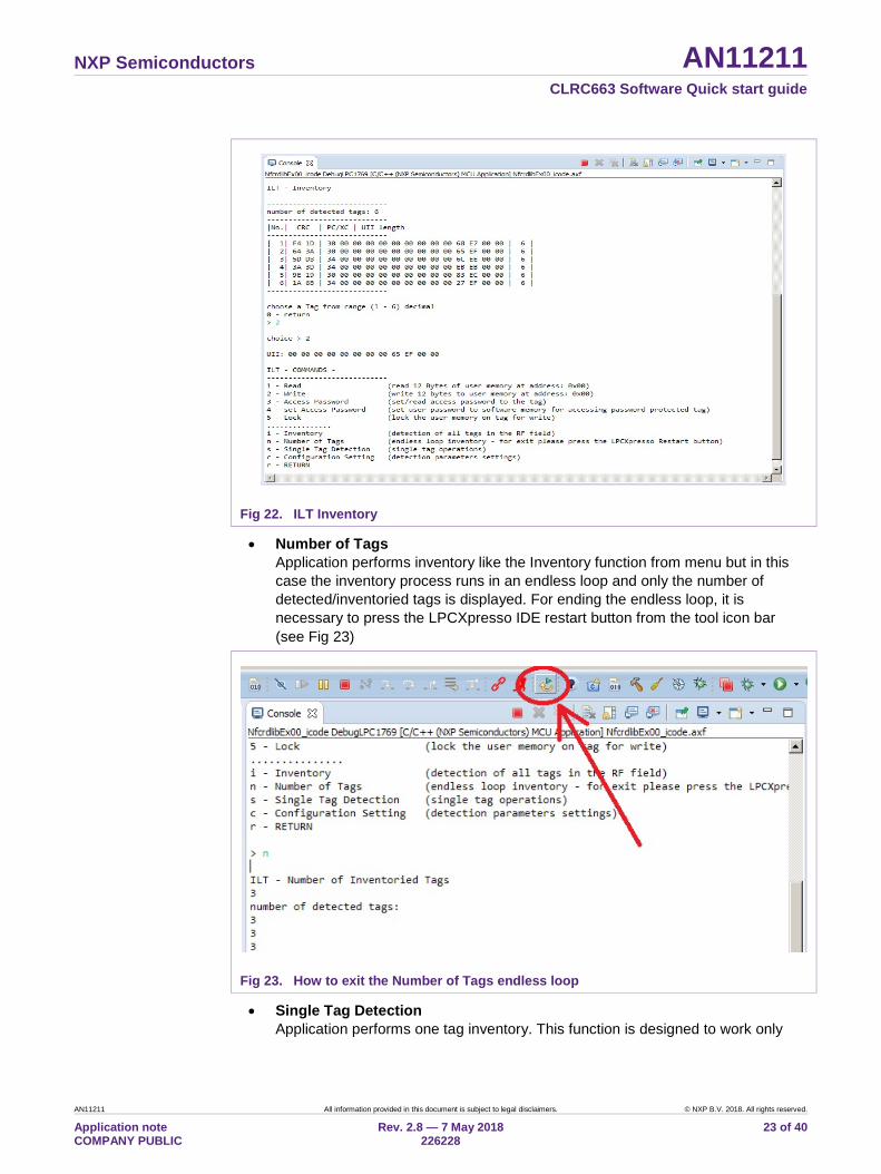
• Inventory Application performs the inventory of all ILT tags which are placed in the RF field. After the inventory process the list of all found tags is printed out in the console window in the LPCXpresso IDE. The listed table consists of the stored CRC and whole PC/XC data packet. The PC/XC consists the UII (Fig 22) The maximum number of detected tags is limited by the power of the RF field of the RC663 Blueboard. Part of the inventory functionality is choosing a certain tag for further operations.
Note: Choosing the tag feature: - The user is asked to choose the tag he wants to choose for further operations by typing the number which is written next to the tags UII in the listing after inventory. Entering ‘0’ means no tag chosen and the program goes back to the menu. Any non-number character is interpreted as zero. Only first 3 characters are taken as input. If just one tag is detected by Inventory, the tag is automatically chosen by the software. In case no tag is detected it is necessary to repeat the inventory. All later operations are performed with the chosen tag in masked mode. The whole UII is taken for mask usage.
NXP Semiconductors AN11211 CLRC663 Software Quick start guide
AN11211 All information provided in this document is subject to legal disclaimers. © NXP B.V. 2018. All rights reserved.
Application note COMPANY PUBLIC
Rev. 2.8 — 7 May 2018 226228
23 of 40
Fig 22. ILT Inventory
• Number of Tags Application performs inventory like the Inventory function from menu but in this case the inventory process runs in an endless loop and only the number of detected/inventoried tags is displayed. For ending the endless loop, it is necessary to press the LPCXpresso IDE restart button from the tool icon bar (see Fig 23)
Fig 23. How to exit the Number of Tags endless loop
• Single Tag Detection Application performs one tag inventory. This function is designed to work only
NXP Semiconductors AN11211 CLRC663 Software Quick start guide
AN11211 All information provided in this document is subject to legal disclaimers. © NXP B.V. 2018. All rights reserved.
Application note COMPANY PUBLIC
Rev. 2.8 — 7 May 2018 226228
24 of 40
with one tag. In case more tags are in the field the “Multiple tags detected” message is displayed in the console. The purpose of this method is to significantly speed up working with a single tag. Other operations (read, write, lock, access) can be performed without any limitation.
Note: All operations are performed with the chosen tag in non-masked mode. UII is not stored for executing further commands. In case no tag or more than one tag are detected, it is necessary repeat the inventory.
• Configuration Setting Application allows setting and changing parameters that affect detection of tags (inventory method) and accessing the tag. All parameters for the detection and accessing are handled as variables in the code. These variables are set to the default values during the software initialization or via this function by setting Default_SetConfig_18000p3m3.
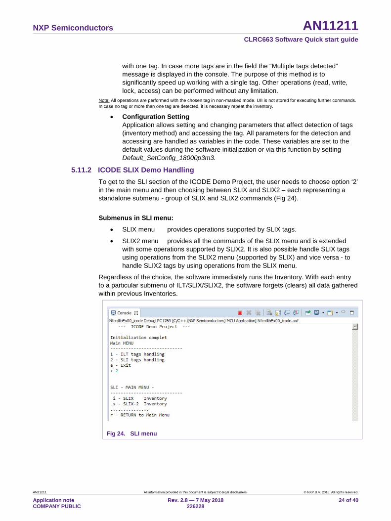
5.11.2 ICODE SLIX Demo Handling To get to the SLI section of the ICODE Demo Project, the user needs to choose option ‘2’ in the main menu and then choosing between SLIX and SLIX2 – each representing a standalone submenu - group of SLIX and SLIX2 commands (Fig 24).
Submenus in SLI menu:
• SLIX menu provides operations supported by SLIX tags.
• SLIX2 menu provides all the commands of the SLIX menu and is extended with some operations supported by SLIX2. It is also possible handle SLIX tags using operations from the SLIX2 menu (supported by SLIX) and vice versa - to handle SLIX2 tags by using operations from the SLIX menu.
Regardless of the choice, the software immediately runs the Inventory. With each entry to a particular submenu of ILT/SLIX/SLIX2, the software forgets (clears) all data gathered within previous Inventories.
Fig 24. SLI menu
NXP Semiconductors AN11211 CLRC663 Software Quick start guide
AN11211 All information provided in this document is subject to legal disclaimers. © NXP B.V. 2018. All rights reserved.
Application note COMPANY PUBLIC
Rev. 2.8 — 7 May 2018 226228
25 of 40
• Inventory The method performs the Inventory command in order to find as much ICODE SLI(X)(2) tags as possible.
Note 1: Internally the function operates recursively – when a collision occurs, the same method is called with the collided UID
Mask Value and Mask bit length increased by 4. Inventory runs in 16 number slot mode.
As a result it lists detected tags in the following pattern: Number | type | UID
o Number – the number of the detected tag sorted by UID. From 1 to N, where N is number of successfully detected tags.
o Type - type of the detected tag. Type can be one of following: SLI, SLIX, SLIX2, RFU. It is identified based on the 36th and 37th bit of the UID
o UID - 64 bit unique identifier of the tag, gained from the response during the Inventory request from each individual tag.
Note 3: Choosing the tag feature – The user is asked to type the number of the desired tag. Entering ‘0’ means no tag chosen and the program returns to the command menu. Any non-number character is interpreted as zero. Only first 3 characters are taken as input. If just one single tag is detected by the Inventory method, the tag is automatically chosen by software. All later operations are performed with the chosen tag, unless Non-addressed mode is selected for particular operation or until new Inventory command. If there is no specific tag chosen all later “addressed operations” fail. In such case it is recommended to re-Inventory or perform Non-addressed operation (Reset To Ready (one-shot), Reset To Ready Loop, Write Single Block).
• Read Single Block Application performs the Read Single Block command (0x20). By default, it reads 4 bytes from block 0. To read another block it’s necessary to modify the value of the BLOCK_NUM_READ_SINGLE_BLOCK macro. The ICODE Demo Project provides this command only in Non-addressed mode.
• Write Single Block Application performs the Write Single Block command (0x21). By default, it writes 4 bytes to block 0. To write another block it is necessary to modify the value of the BLOCK_NUM_WRITE_SINGLE_BLOCK macro. User can choose whether to write “NXP_” or clear the block (write four zeros). This command is provided by the ICODE Demo Project in Addressed mode and Non-addressed mode as well.
Note: Non-addressed mode (write to all tags) is provided even if there has been just one tag detected in previous Inventory.
• Read multiple blocks Application performs The Read Multiple Blocks command (0x23). By default, it reads blocks 0 and 1 (resulting in reading 8 bytes). To start reading form another block it is necessary to modify the value of the FIRST_BLOCK_NUM_READ_MULTIPLE_BLOCKS macro. Reading different length of tag memory is possible via changing the NUM_OF_BLOCKS_READ_MULTIPLE_BLOCKS macro. This command is provided by the ICODE Demo Project only in Non-addressed mode.
Note: This command is not supported by SLI-L and SLI-S tags. When attempting to perform this command with those tag types, only a vague error message “ERROR – Read Multiple Blocks” is printed.
• Stay Quiet Application performs Stay Quiet command (0x02) over the previously chosen tag. The tag in Quiet state cannot be detected by Inventory. The tag stays in Quiet state until power off (removed from RF field) or Reset To Ready or Broadcast Reset Loop is applied.
NXP Semiconductors AN11211 CLRC663 Software Quick start guide
AN11211 All information provided in this document is subject to legal disclaimers. © NXP B.V. 2018. All rights reserved.
Application note COMPANY PUBLIC
Rev. 2.8 — 7 May 2018 226228
26 of 40
Note: It is not possible to recognize whether requested tag has been really turned to the Quiet state or the command has not been caught by the tag (tag out of range of RF field) because the tag gives no response (and operation returns with success) in both of the situations.
• Reset tag(s) to ready Application performs Reset To Ready command (0x26) once. This operation is provided by ICODE Demo Project in both, the Addressed and Non-addressed mode. All tags in Quiet (or Persistent Quiet SLIX-2) state requested by this command are transferred to Ready state and can be detected by Inventory again.
• Broadcast reset loop Application performs Reset To Ready command (0x26) in loop for given amount of time (from 1 to 9 seconds). During that time nothing but transmission of Reset To Ready in Non-Addressed mode is executed – the operation is a blocker. The operation does not provide Addressed mode – the Reset to Ready commands are always transmitted to all the tags in the field.
Note: During execution the application claims one OSAL timer. The timer is released as soon as the loop ends.
5.11.3 ICODE SLIX-2 Demo Handling • Read Single Block
See Read Single Block in section 5.11.2.
• Write Single Block See Write Single Block in section 5.11.2.
• Read Multiple Block See Read Multiple Blocks in section 5.11.2.
• Get NXP System Information Application performs Get NXP System Information command (0xAB) on a previously chosen tag. The output provides information about the memory structure and protection status of particular L and H pages.
• Set Password Application performs Get Random Number command (0xB2) and Set Password command (0xB3) on a previously chosen tag. The software provides “log in” only with read or write password. This operation needs to be executed prior to Write Password, Lock Password or Protect Page command. If Protect Page is intended to be called, the Set Password function must be called twice prior to Protect Page, once for writing and once for reading. If a page is read or (and) write protected, this operation must be called prior to Read Single Block (Read Multiple Blocks) or (and) Write Single Block operation.
Note: Console error message “ERROR - Set Password command is not supported by chosen tag” is printed either when the requested tag is not capable to perform the operation (for example an SLI tag is requested) or also in case the password is incorrect.
Precondition: Prior to this operation, Set Password needs to be run.
• Write Password Application performs Write Password command (0xB4) on previously chosen tag. Application supports just changing of write and read password. Password identifier (read/write) has to be chosen
Note: Choosing the Password identifier (read/write) is provided only by the Set Password command. The software uses for the Write Password command the same password identifier.
NXP Semiconductors AN11211 CLRC663 Software Quick start guide
AN11211 All information provided in this document is subject to legal disclaimers. © NXP B.V. 2018. All rights reserved.
Application note COMPANY PUBLIC
Rev. 2.8 — 7 May 2018 226228
27 of 40
• Lock Password Application performs Lock Password Setting a new Password and placing a subsequently Lock, can be done in the following steps:
• 1) Set Password 2) Write Password with new password 3) Set Password with the new password 4) Lock Password with new password
Precondition: Prior to this operation Set Password need to be run.
Note: Choosing the Password identifier is only provided with Set Password. The software uses for Lock Password the same password identifier.
• Protect Page Application performs Lock Password command (0xB6) while dividing tag memory into L and H page on address 0x0A. The operation provides possibility to protect L page for reading, H page for reading, L page for writing, H page for writing and clearing all protection flags at once.
Preconditions: Prior to Protect Page the Set Password must be called twice – for both reading and writing.
Note 1: Setting of more protection flags can be done only one by one, without necessity to call Set Password between particular page protection settings.
Note 2: To prevent unintended transfer of page protection configuration from one tag to another, the user needs to be aware that the last page protection configuration stays stored in the software. Clear protect page clears the last setting stored in the software but, it also clears current page protection configuration on currently chosen tag (meaning, it is not possible to clear page protection configuration in the software without applying it to the chosen tag).
• Stay Quiet See Stay Quiet in section 5.11.2.
• Stay Quiet Persistent Application performs Stay Quiet Persistent command (0xBC) on previously chosen tag. Tags in Stay Quiet Persistent state cannot be detected by Inventory. The tag stays in Persistent Quiet state until it is powered off (removed from RF field), persistent time is exceeded (tens of seconds depending on temperature) or Reset To Ready or Broadcast Reset Loop is applied.
Note: It is not possible to recognize whether requested tag has been really turned to the Persistent Quiet state or the command has not been caught by the tag (tag out of range of RF field) because the tag gives no response in both situations.
• Reset tag(s) to ready See Reset tag(s) to ready in section 5.11.2.
• Broadcast reset loop See Broadcast reset loop in section 5.11.2.
5.11.4 ICODE SLI/SLIX-2 software and configurations There are a few #define values, that influence the behavior of the ICODE SLIX Demo software.
• Macro input parameters for commands. In the icode_sli_ui.c there are defined macros, which are used as input values for some commands.
o #define BLOCK_NUM_READ_SINGLE_BLOCK 0 Number of blocks from which the Read Single Block command reads 4 bytes.
NXP Semiconductors AN11211 CLRC663 Software Quick start guide
AN11211 All information provided in this document is subject to legal disclaimers. © NXP B.V. 2018. All rights reserved.
Application note COMPANY PUBLIC
Rev. 2.8 — 7 May 2018 226228
28 of 40
o #define BLOCK_NUM_WRITE_SINGLE_BLOCK 0 Number of blocks to which the Write Single Block command writes 4 bytes.
o #define FIRST_BLOCK_NUM_READ_MULTIPLE_BLOCKS 0 Number of the first block from which the Read Multiple Blocks command starts reading.
o #define NUM_OF_BLOCKS_READ_MULTIPLE_BLOCKS 2 Number of the block at which the Read Multiple Blocks command stops reading.
These macros can be customized with respect to the memory boundaries of the tags to be handled.
• MAX_NUM_DETECTED_SLI_TAGS defines how many SLI tags the application can store. Although it is possible to detect more tags during inventory, this value limits the number of tags stored by the application.
• SPRINTF_BUFFER_SIZE defines the number of bytes that are pre-buffered and printed in one frame during listing of the detected tags. If listing the inventoried tags causes a stack overflow, it is recommended to set the value of this macro to a lower value.
NXP Semiconductors AN11211 CLRC663 Software Quick start guide
AN11211 All information provided in this document is subject to legal disclaimers. © NXP B.V. 2018. All rights reserved.
Application note COMPANY PUBLIC
Rev. 2.8 — 7 May 2018 226228
29 of 40
6. Supplementary Notes Fore detailed API description of the NFC Reader Library please refer to the chm help file located at NFC_Reader_Library\docs\14_user_doc\NXP NFC Reader Library.chm.
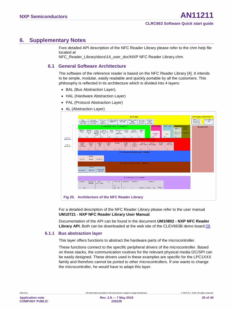
6.1 General Software Architecture The software of the reference reader is based on the NFC Reader Library [4]. It intends to be simple, modular, easily readable and quickly portable by all the customers. This philosophy is reflected in its architecture which is divided into 4 layers: • BAL (Bus Abstraction Layer), • HAL (Hardware Abstraction Layer) • PAL (Protocol Abstraction Layer) • AL (Abstraction Layer)
Fig 25. Architecture of the NFC Reader Library
For a detailed description of the NFC Reader Library please refer to the user manual UM10721 - NXP NFC Reader Library User Manual. Documentation of the API can be found in the document UM10802 - NXP NFC Reader Library API. Both can be downloaded at the web site of the CLEV663B demo board [3].
6.1.1 Bus abstraction layer This layer offers functions to abstract the hardware parts of the microcontroller.
These functions connect to the specific peripheral drivers of the microcontroller. Based on these stacks, the communication routines for the relevant physical media I2C/SPI can be easily designed. These drivers used in these examples are specific for the LPC1XXX family and therefore cannot be ported to other microcontrollers. If one wants to change the microcontroller, he would have to adapt this layer.
NXP Semiconductors AN11211 CLRC663 Software Quick start guide
AN11211 All information provided in this document is subject to legal disclaimers. © NXP B.V. 2018. All rights reserved.
Application note COMPANY PUBLIC
Rev. 2.8 — 7 May 2018 226228
30 of 40
6.1.2 Hardware abstraction layer This layer offers functions to abstract the hardware parts of the supported transceivers.
6.1.3 Protocol abstraction layer Every PAL function is a low-level function realizing a single functionality. It is encapsulated in a module which is independent from the others. The user can easily design his application by doing a drag-and-drop of the relevant module.
The following PAL modules are available in this software package: • ISO/IEC 14443-3A, • ISO/IEC 14443-3B, • ISO/IEC 14443-4, • MIFARE product • ISO/IEC 14443-4mC • FeliCa, • NFC Initiator • NFC Target • ISO/IEC 15693 • ISO/IEC 18000-3 Mode 3
6.1.4 Application layer Lying on the previous software layers, the application layer is on top of the reader software package. It combines elements of the previous three parts into high level functionalities.
6.1.5 NFC Activity This component provides the Discovery Loop component. It implements poll mode based on NFC Activity Specification 1.1 (backward compatibility with version 1.0) and EMVCo Specification 2.3.1a. Listen mode is implemented based on NFC Activity Specification 1.1. Support for Type V (ISO 15693) polling is included based on NFC Forum draft specification. ISO 18000-3 Mode 3 (EPC Gen2) is supported as a proprietary technology in poll mode.
6.1.6 HCE Layer This component implements the card emulation of NFC Forum Type 4A Tag.
The implementation is based on NFC Forum Type 4 Tag Operation Specification version 2.0. SELECT, READ BINARY and UPDATE BINARY commands are supported as per NFC Forum Type 4 Tag Operation Specification.
This layer follows a multi-threaded RTOS based design using one reader library thread and one application thread. Application thread along with application callback can be used for handling of UPDATE BINARY and proprietary commands.
A pictorial representation of reader library thread and application thread used for card emulation is shown below. Refer function documentation for more information.
NXP Semiconductors AN11211 CLRC663 Software Quick start guide
AN11211 All information provided in this document is subject to legal disclaimers. © NXP B.V. 2018. All rights reserved.
Application note COMPANY PUBLIC
Rev. 2.8 — 7 May 2018 226228
31 of 40
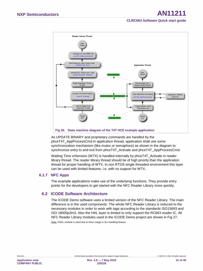
Fig 26. State machine diagram of the T4T HCE example application
As UPDATE BINARY and proprietary commands are handled by the phceT4T_AppProcessCmd in application thread, application shall use some synchronization mechanism (like mutex or semaphore) as shown in the diagram to synchronize entry to and exit from phceT4T_Activate and phceT4T_AppProcessCmd.
Waiting Time eXtension (WTX) is handled internally by phceT4T_Activate in reader library thread. The reader library thread should be of high priority than the application thread for proper handling of WTX. In non RTOS single threaded environment this layer can be used with limited features, i.e. with no support for WTX.
6.1.7 NFC Apps The example applications make use of the underlying functions. They provide entry points for the developers to get started with the NFC Reader Library more quickly.
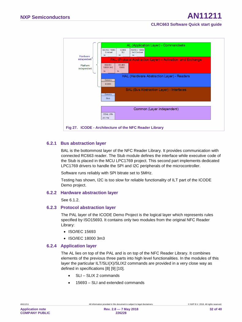
6.2 ICODE Software Architecture The ICODE Demo software uses a limited version of the NFC Reader Library. The main difference is in the used components. The whole NFC Reader Library is reduced to the necessary modules in order to work with tags according to the standards ISO15693 and ISO 18000p3m3. Also the HAL layer is limited to only support the RC663 reader IC. All NFC Reader Library modules used in the ICODE Demo project are shown in Fig 27. Note: OSAL module is used due to timer usage in SLI handling feature.
NXP Semiconductors AN11211 CLRC663 Software Quick start guide
AN11211 All information provided in this document is subject to legal disclaimers. © NXP B.V. 2018. All rights reserved.
Application note COMPANY PUBLIC
Rev. 2.8 — 7 May 2018 226228
32 of 40
Fig 27. ICODE - Architecture of the NFC Reader Library
6.2.1 Bus abstraction layer BAL is the bottommost layer of the NFC Reader Library. It provides communication with connected RC663 reader. The Stub module defines the interface while executive code of the Stub is placed in the MCU LPC1769 project. This second part implements dedicated LPC1769 drivers to handle the SPI and I2C peripherals of the microcontroller.
Software runs reliably with SPI bitrate set to 5MHz.
Testing has shown, I2C is too slow for reliable functionality of ILT part of the ICODE Demo project.
6.2.2 Hardware abstraction layer See 6.1.2.
6.2.3 Protocol abstraction layer The PAL layer of the ICODE Demo Project is the logical layer which represents rules specified by ISO15693. It contains only two modules from the original NFC Reader Library: • ISO/IEC 15693 • ISO/IEC 18000 3m3
6.2.4 Application layer The AL lies on top of the PAL and is on top of the NFC Reader Library. It combines elements of the previous three parts into high level functionalities. In the modules of this layer the particular ILT/SLI(X)/SLIX2 commands are provided in a very close way as defined in specifications [8] [9] [10].
• SLI – SLIX 2 commands
• 15693 – SLI and extended commands
NXP Semiconductors AN11211 CLRC663 Software Quick start guide
AN11211 All information provided in this document is subject to legal disclaimers. © NXP B.V. 2018. All rights reserved.
Application note COMPANY PUBLIC
Rev. 2.8 — 7 May 2018 226228
33 of 40
• ILT – ILT Access commands
6.3 Build configuration All the projects mentioned in Chapter 5 are available in debug and release configuration. • Debug configuration
This configuration is mainly used when the target board is attached to the PC with the JTAG debugger. It allows the display of debug messages in the console window, which is useful in the early stage of the project.
• Release configuration Once the project is debugged and mature, it might be interesting to use the release configuration, to use the hardware stand alone. No debug messages are displayed in the console window. Note, that only in Release Configuration one can flash the software onto the Blueboard and start it automatically, once power has been attached to the board.
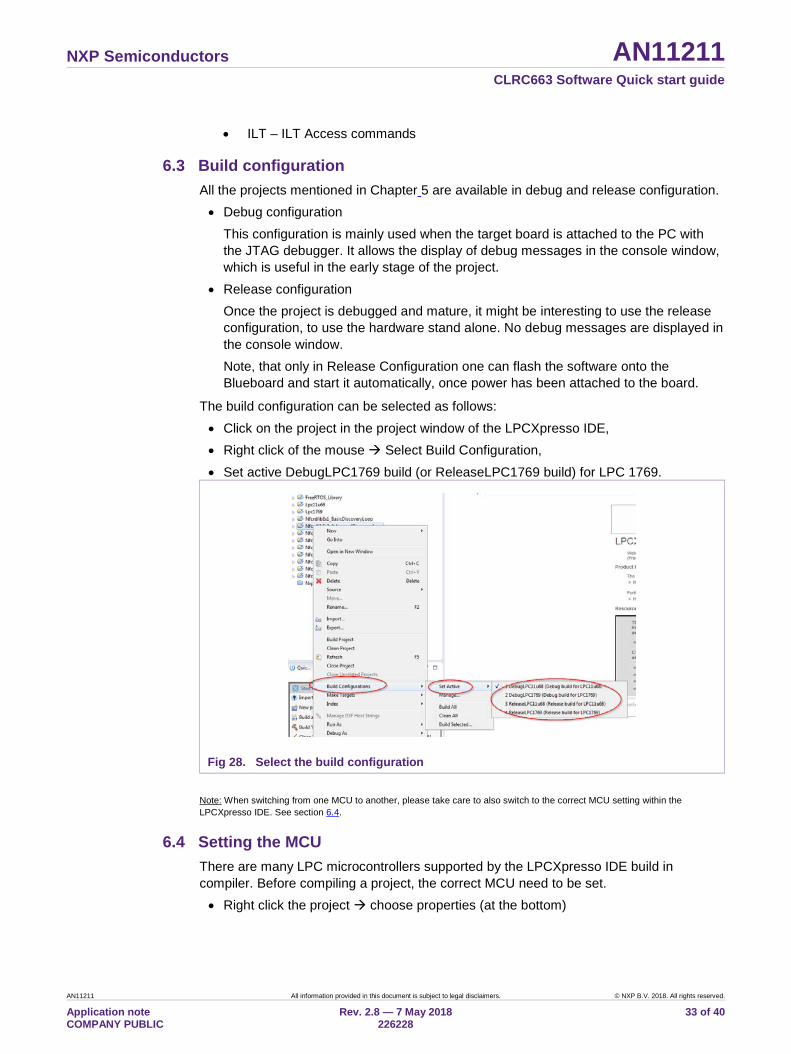
The build configuration can be selected as follows: • Click on the project in the project window of the LPCXpresso IDE, • Right click of the mouse Select Build Configuration, • Set active DebugLPC1769 build (or ReleaseLPC1769 build) for LPC 1769.
Fig 28. Select the build configuration Note: When switching from one MCU to another, please take care to also switch to the correct MCU setting within the LPCXpresso IDE. See section 6.4.
6.4 Setting the MCU There are many LPC microcontrollers supported by the LPCXpresso IDE build in compiler. Before compiling a project, the correct MCU need to be set. • Right click the project choose properties (at the bottom)
NXP Semiconductors AN11211 CLRC663 Software Quick start guide
AN11211 All information provided in this document is subject to legal disclaimers. © NXP B.V. 2018. All rights reserved.
Application note COMPANY PUBLIC
Rev. 2.8 — 7 May 2018 226228
34 of 40
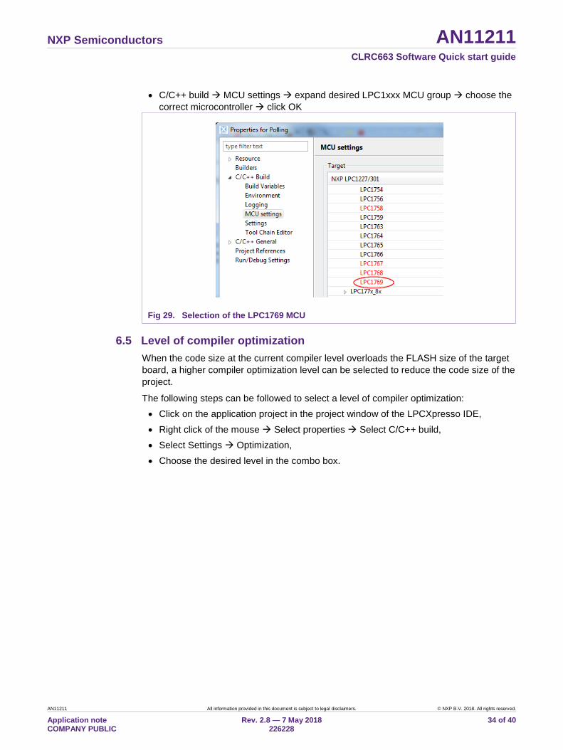
• C/C++ build MCU settings expand desired LPC1xxx MCU group choose the correct microcontroller click OK
Fig 29. Selection of the LPC1769 MCU
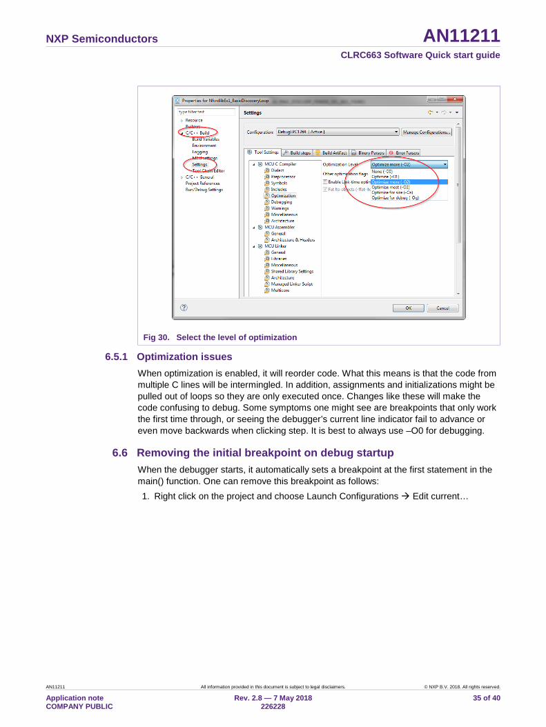
6.5 Level of compiler optimization When the code size at the current compiler level overloads the FLASH size of the target board, a higher compiler optimization level can be selected to reduce the code size of the project.
The following steps can be followed to select a level of compiler optimization: • Click on the application project in the project window of the LPCXpresso IDE, • Right click of the mouse Select properties Select C/C++ build, • Select Settings Optimization, • Choose the desired level in the combo box.
NXP Semiconductors AN11211 CLRC663 Software Quick start guide
AN11211 All information provided in this document is subject to legal disclaimers. © NXP B.V. 2018. All rights reserved.
Application note COMPANY PUBLIC
Rev. 2.8 — 7 May 2018 226228
35 of 40
Fig 30. Select the level of optimization
6.5.1 Optimization issues When optimization is enabled, it will reorder code. What this means is that the code from multiple C lines will be intermingled. In addition, assignments and initializations might be pulled out of loops so they are only executed once. Changes like these will make the code confusing to debug. Some symptoms one might see are breakpoints that only work the first time through, or seeing the debugger’s current line indicator fail to advance or even move backwards when clicking step. It is best to always use –O0 for debugging.
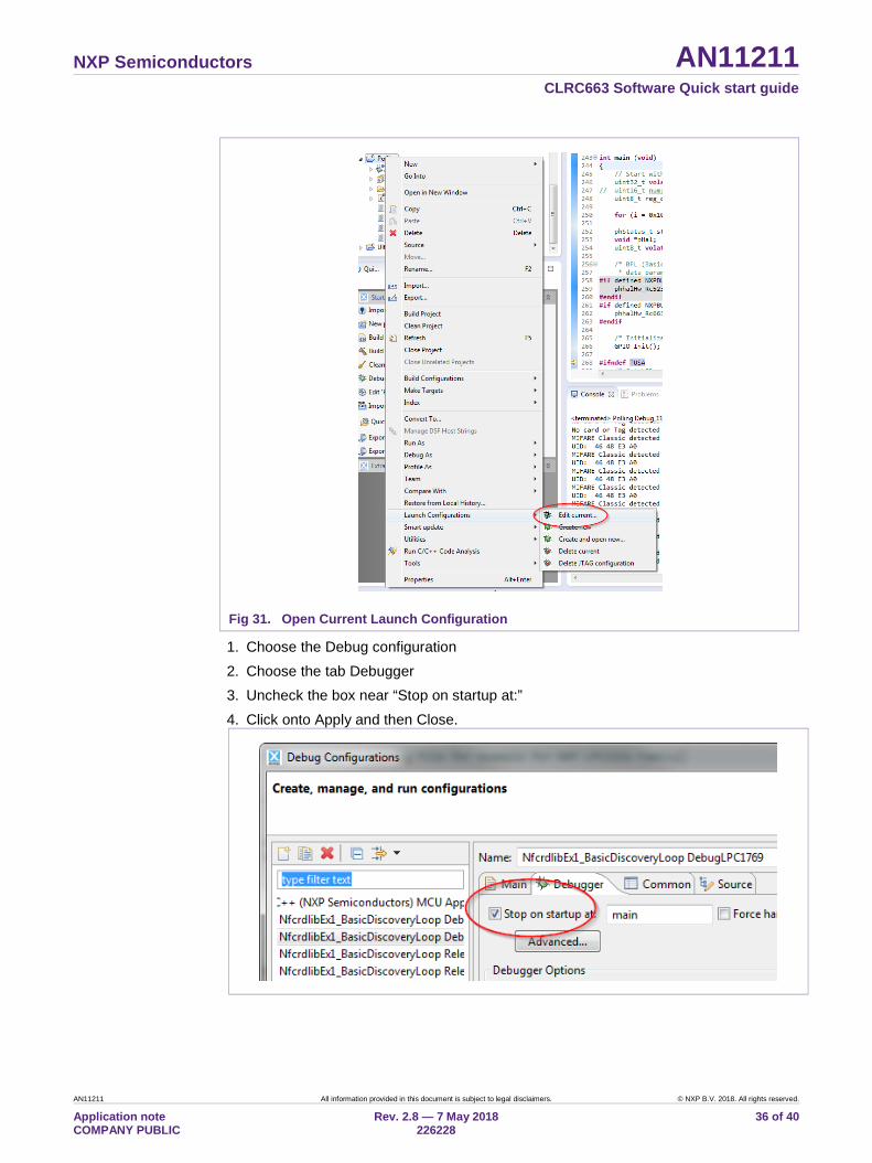
6.6 Removing the initial breakpoint on debug startup When the debugger starts, it automatically sets a breakpoint at the first statement in the main() function. One can remove this breakpoint as follows: 1. Right click on the project and choose Launch Configurations Edit current…
NXP Semiconductors AN11211 CLRC663 Software Quick start guide
AN11211 All information provided in this document is subject to legal disclaimers. © NXP B.V. 2018. All rights reserved.
Application note COMPANY PUBLIC
Rev. 2.8 — 7 May 2018 226228
36 of 40
Fig 31. Open Current Launch Configuration
1. Choose the Debug configuration 2. Choose the tab Debugger 3. Uncheck the box near “Stop on startup at:” 4. Click onto Apply and then Close.
NXP Semiconductors AN11211 CLRC663 Software Quick start guide
AN11211 All information provided in this document is subject to legal disclaimers. © NXP B.V. 2018. All rights reserved.
Application note COMPANY PUBLIC
Rev. 2.8 — 7 May 2018 226228
37 of 40
7. References [1] LPCXpresso website
http://www.lpcware.com/lpcxpresso/download
[2] RC663 data sheet http://www.nxp.com/documents/data_sheet/CLRC663.pdf
[3] CLEV6630B demo board site http://www.nxp.com/demoboard/CLEV663B.html
[4] NXP NFC Reader Library User Manual http://www.nxp.com/documents/user_manual/UM10721.pdf
[5] Technical Specification – Simple NDEF Exchange Protocol, NFCForum-TS-SNEP_1.0 http://www.nfc-forum.org/specs/spec_license
[6] EMV – The table of card types and their matching AIDs are available on http://www.en.wikipedia.org/wiki/EMV
[7] EXPLORE-NFC product page http://www.nxp.com/demoboard/PNEV512R.html#documentation
[8] ISO/IEC 18000-3:2010(E) Information technology — Radio frequency identification for item management Part 3: Parameters for air interface communications at 13,56 MHz Third Edition 2010-11-15
[9] ISO/IEC 15693-3 Identification cards — Contactless integrated circuit cards — Vicinity cards Part 3: Anticollision and transmission protocol Second Edition 2009-04-15
[10] SLIX2 – datasheet with custom commands specification http://www.nxp.com/documents/data_sheet/SL2S2602.pdf
[11] CLRC663 Antenna Design Guide http://www.nxp.com/documents/application_note/AN11019.pdf
[12] CLEV663B software and documents download http://www.nxp.com/board/CLEV663B.html#documentation
[13] NTAG-I2C http://www.nxp.com/products/identification_and_security/nfc_and_reader_ics/connected_tag_solutions/series/NT3H1101_NT3H1201.html
NXP Semiconductors AN11211 CLRC663 Software Quick start guide
AN11211 All information provided in this document is subject to legal disclaimers. © NXP B V. 2018. All rights reserved.
Application note COMPANY PUBLIC
Rev. 2.8 — 7 May 2018 226228
38 of 40
8. Legal information
8.1 Definitions Draft — The document is a draft version only. The content is still under internal review and subject to formal approval, which may result in modifications or additions. NXP Semiconductors does not give any representations or warranties as to the accuracy or completeness of information included herein and shall have no liability for the consequences of use of such information.
8.2 Disclaimers Limited warranty and liability — Information in this document is believed to be accurate and reliable. However, NXP Semiconductors does not give any representations or warranties, expressed or implied, as to the accuracy or completeness of such information and shall have no liability for the consequences of use of such information. NXP Semiconductors takes no responsibility for the content in this document if provided by an information source outside of NXP Semiconductors.
In no event shall NXP Semiconductors be liable for any indirect, incidental, punitive, special or consequential damages (including - without limitation - lost profits, lost savings, business interruption, costs related to the removal or replacement of any products or rework charges) whether or not such damages are based on tort (including negligence), warranty, breach of contract or any other legal theory.
Notwithstanding any damages that customer might incur for any reason whatsoever, NXP Semiconductors’ aggregate and cumulative liability towards customer for the products described herein shall be limited in accordance with the Terms and conditions of commercial sale of NXP Semiconductors.
Right to make changes — NXP Semiconductors reserves the right to make changes to information published in this document, including without limitation specifications and product descriptions, at any time and without notice. This document supersedes and replaces all information supplied prior to the publication hereof.
Suitability for use — NXP Semiconductors products are not designed, authorized or warranted to be suitable for use in life support, life-critical or safety-critical systems or equipment, nor in applications where failure or malfunction of an NXP Semiconductors product can reasonably be expected to result in personal injury, death or severe property or environmental damage. NXP Semiconductors and its suppliers accept no liability for inclusion and/or use of NXP Semiconductors products in such equipment or applications and therefore such inclusion and/or use is at the customer’s own risk.
Applications — Applications that are described herein for any of these products are for illustrative purposes only. NXP Semiconductors makes no representation or warranty that such applications will be suitable for the specified use without further testing or modification.
Customers are responsible for the design and operation of their applications and products using NXP Semiconductors products, and NXP Semiconductors accepts no liability for any assistance with applications or customer product design. It is customer’s sole responsibility to determine whether the NXP Semiconductors product is suitable and fit for the customer’s applications and products planned, as well as for the planned application and use of customer’s third party customer(s). Customers should provide appropriate design and operating safeguards to minimize the risks associated with their applications and products.
NXP Semiconductors does not accept any liability related to any default, damage, costs or problem which is based on any weakness or default in the customer’s applications or products, or the application or use by customer’s third party customer(s). Customer is responsible for doing all necessary testing for the customer’s applications and products using NXP
Semiconductors products in order to avoid a default of the applications and the products or of the application or use by customer’s third party customer(s). NXP does not accept any liability in this respect.
Export control — This document as well as the item(s) described herein may be subject to export control regulations. Export might require a prior authorization from competent authorities.
Translations — A non-English (translated) version of a document is for reference only. The English version shall prevail in case of any discrepancy between the translated and English versions.
Evaluation products — This product is provided on an “as is” and “with all faults” basis for evaluation purposes only. NXP Semiconductors, its affiliates and their suppliers expressly disclaim all warranties, whether express, implied or statutory, including but not limited to the implied warranties of non-infringement, merchantability and fitness for a particular purpose. The entire risk as to the quality, or arising out of the use or performance, of this product remains with customer.
In no event shall NXP Semiconductors, its affiliates or their suppliers be liable to customer for any special, indirect, consequential, punitive or incidental damages (including without limitation damages for loss of business, business interruption, loss of use, loss of data or information, and the like) arising out the use of or inability to use the product, whether or not based on tort (including negligence), strict liability, breach of contract, breach of warranty or any other theory, even if advised of the possibility of such damages.
Notwithstanding any damages that customer might incur for any reason whatsoever (including without limitation, all damages referenced above and all direct or general damages), the entire liability of NXP Semiconductors, its affiliates and their suppliers and customer’s exclusive remedy for all of the foregoing shall be limited to actual damages incurred by customer based on reasonable reliance up to the greater of the amount actually paid by customer for the product or five dollars (US$5.00). The foregoing limitations, exclusions and disclaimers shall apply to the maximum extent permitted by applicable law, even if any remedy fails of its essential purpose.
8.3 Licenses Purchase of NXP ICs with ISO/IEC 14443 type B functionality
This NXP Semiconductors IC is ISO/IEC 14443 Type B software enabled and is licensed under Innovatron’s Contactless Card patents license for ISO/IEC 14443 B.
The license includes the right to use the IC in systems and/or end-user equipment.
RATP/Innovatron Technology
8.4 Trademarks Notice: All referenced brands, product names, service names and trademarks are property of their respective owners.
MIFARE— is a trademark of NXP B.V.
MIFARE Classic — is a trademark of NXP B.V.
DESFire — is a trademark of NXP B.V.
MIFARE Ultralight — is a trademark of NXP B.V.
ICODE — is a trademark of NXP B.V.
NTAG — is a trademark of NXP B.V.
Kinetis — is a trademark of NXP B.V.
NXP Semiconductors AN11211 CLRC663 Software Quick start guide
AN11211 All information provided in this document is subject to legal disclaimers. © NXP B.V. 2018. All rights reserved.
Application note COMPANY PUBLIC
Rev. 2.8 — 7 May 2018 226228
39 of 40
9. List of figures
Fig 1. Picture of RC663 demo board ........................... 4 Fig 2. Picture of jumper settings.................................. 5 Fig 3. LPCXpresso installation NXP Debug drivers .... 6 Fig 4. Windows Security dialog ................................... 7 Fig 5. LPCXpresso IDE ............................................... 7 Fig 6. Product activation (1) ........................................ 8 Fig 7. Product activation (2) ........................................ 8 Fig 8. Product activation (3) ........................................ 9 Fig 9. Importing project (1) ........................................ 10 Fig 10. Importing project (2) ........................................ 10 Fig 11. Importing project (3) ........................................ 11 Fig 12. CLEV6630B with LPC-Link2 ........................... 12 Fig 13. Launch debug session .................................... 12 Fig 14. Successful compile ......................................... 13 Fig 15. Select the launch configuration ....................... 13 Fig 16. Debug project .................................................. 14
Fig 17. Application printouts in Console window ......... 14 Fig 18. Debug Buttons ................................................ 15 Fig 19. Debug Buttons ................................................ 15 Fig 20. Discovery Loop in Poll mode ........................... 17 Fig 21. ILT menu ......................................................... 21 Fig 22. ILT Inventory ................................................... 23 Fig 23. How to exit the Number of Tags endless loop . 23 Fig 24. SLI menu ......................................................... 24 Fig 25. Architecture of the NFC Reader Library .......... 29 Fig 26. State machine diagram of the T4T HCE
example application ........................................ 31 Fig 27. ICODE - Architecture of the NFC Reader Library
........................................................................ 32 Fig 28. Select the build configuration .......................... 33 Fig 29. Selection of the LPC1769 MCU ...................... 34 Fig 30. Select the level of optimization ........................ 35 Fig 31. Open Current Launch Configuration ............... 36
NXP Semiconductors AN11211 CLRC663 Software Quick start guide
Please be aware that important notices concerning this document and the product(s) described herein, have been included in the section 'Legal information'.
© NXP B.V. 2018. All rights reserved. For more information, visit: http://www.nxp.com
Date of release: 7 May 2018 226228 Document identifier: AN11211
10. Contents
1. Introduction ......................................................... 3 2. Hardware overview of the Demo Board ............. 4 2.1 CLEV6630B demo board (Blueboard) ................ 4 2.2 CE certification of the Blueboard ........................ 5 3. Managing the Demo Reader project with
LPCXpresso IDE .................................................. 6 3.1 Development environment ................................. 6 3.2 Installation of LPCXpresso IDE .......................... 6 3.3 Extraction of the demo reader project ................ 9 3.4 Running and debugging a project .................... 11 4. Managing the CL663 SW projects with Linux
and KDS IDE ...................................................... 15 5. Associated Projects .......................................... 15 5.1 Example 1 – Basic Discovery Loop .................. 16 5.2 Example 2 – Advanced Discovery Loop ........... 18 5.3 Example 4 – MIFARE Classic card
communication ................................................. 18 5.4 Example 5 - ISO15693 ..................................... 18 5.5 Example 7 – EMVCo Polling ............................ 18 5.6 Example 9 – NTAG I2C .................................... 18 5.7 Example 10 – MIFARE DESFire card
communication ................................................. 19 5.8 Example 11 – ISO10373 PCD .......................... 19 5.9 SimplifiedAPI EMVCo ...................................... 19 5.10 SimplifiedAPI ISO ............................................. 19 5.11 ICODE Demo Project ....................................... 20 5.11.1 ICODE ILT Demo Handling .............................. 21 5.11.2 ICODE SLIX Demo Handling ........................... 24 5.11.3 ICODE SLIX-2 Demo Handling ........................ 26 5.11.4 ICODE SLI/SLIX-2 software and
configurations ................................................... 27 6. Supplementary Notes ....................................... 29 6.1 General Software Architecture ......................... 29 6.1.1 Bus abstraction layer ........................................ 29 6.1.2 Hardware abstraction layer .............................. 30 6.1.3 Protocol abstraction layer ................................. 30
6.1.4 Application layer ............................................... 30 6.1.5 NFC Activity ...................................................... 30 6.1.6 HCE Layer ........................................................ 30 6.1.7 NFC Apps ......................................................... 31 6.2 ICODE Software Architecture ........................... 31 6.2.1 Bus abstraction layer ........................................ 32 6.2.2 Hardware abstraction layer ............................... 32 6.2.3 Protocol abstraction layer ................................. 32 6.2.4 Application layer ............................................... 32 6.3 Build configuration ............................................ 33 6.4 Setting the MCU ............................................... 33 6.5 Level of compiler optimization .......................... 34 6.5.1 Optimization issues .......................................... 35 6.6 Removing the initial breakpoint on
debug startup ................................................... 35 7. References ......................................................... 37 8. Legal information .............................................. 38 8.1 Definitions ......................................................... 38 8.2 Disclaimers ....................................................... 38 8.3 Licenses ........................................................... 38 8.4 Trademarks ...................................................... 38 9. List of figures ..................................................... 39 10. Contents ............................................................. 40


![NXP POWERPOINT TEMPLATE CONFIDENTIAL · 2017. 5. 31. · •2014: VISA + Mastercard support HCE • [Berg Insight ]: 86% of the Point of Sale devices in North America and 78% in Europe](https://img.pdfslide.us/doc/110x75/5fc377e5afc48174717be4ac/nxp-powerpoint-template-confidential-2017-5-31-a2014-visa-mastercard-support.jpg)