Embed Size (px)
Citation preview

1
An X86 emulator written using Java
A dissertation submitted to the University of Manchester for the degree of Master
of Science in the Faculty of Engineering and Physical Sciences.
2005
Jonathan Kenneth William Burcham
School of Computer Science

2
Contents
Abstract ..................................................................................................................6
Declaration .............................................................................................................7
Copyright ...............................................................................................................8
Acknowledgements................................................................................................9
The Author ...........................................................................................................10
1 Emulation with Pearcolator...............................................................................11
1.1 Emulation ...................................................................................................11
1.2 Pearcolator..................................................................................................12
2 Emulating x86 Linux ........................................................................................13
2.1 Evaluation of the x86 Linux Environment.................................................13
2.2 X86 Architecture........................................................................................14
2.2.1 Overview.............................................................................................14
2.2.2 Registers..............................................................................................14
2.2.3 Addressing Modes...................................................................................18
3 Environment......................................................................................................19
3.1 Introduction................................................................................................19
3.2 Process Space.............................................................................................19
3.2.1 Overview.............................................................................................19
3.2.2 Registers..............................................................................................20
3.2.3 Memory...............................................................................................21
3.2.4 System Calls........................................................................................23
3.3 Binary Loader.............................................................................................25
3.3.1 Introduction.........................................................................................25
3.3.2 Purpose of Binary Formats .................................................................26
3.3.3 The ELF Binary Format......................................................................26
3.3.4 A problem with the Old Binary Loader ..............................................27
3.3.5 Determination of Binary Format.........................................................28
3.3.6 Reading ELF Header...........................................................................29
3.3.7 Creating ELF Program Header Table .................................................29
3.3.8 Reading ELF Program Headers ..........................................................29
3.3.9 Copy Executable Code........................................................................29

3
3.3.10 Copy Initialised Data ........................................................................30
3.3.11 Configure Uninitialised Data ............................................................30
3.3.12 Environment Variables .....................................................................30
3.3.13 Aux Vector........................................................................................31
3.3.14 Stack Initialisation.............................................................................31
4 Register Handling..............................................................................................33
4.1 Introduction................................................................................................33
4.2 Register handling in PowerPC Pearcolator ................................................33
4.3 Register Handling in x86 Pearcolator ........................................................34
4.3.1 Introduction.........................................................................................34
4.3.2 Sub Register Synchronisation Laziness ..............................................35
4.3.3 Removing Unnecessary Fills and Spills..............................................37
4.3.4 First Version........................................................................................37
4.3.5 Second Version ...................................................................................37
4.3.6 Third Version ......................................................................................38
4.3.7 Fourth Version ....................................................................................38
4.3.8 Alternative Implementation ................................................................39
4.4 Flag Handling.............................................................................................41
4.4.1 Introduction.........................................................................................41
4.4.2 Flag Laziness.......................................................................................41
5 Instruction Decoder...........................................................................................42
5.1 Introduction................................................................................................42
5.2 Instruction Format......................................................................................42
5.2.1 Instruction Prefix Field .......................................................................43
5.2.2 Opcode Field .......................................................................................43
5.2.3 ModR/M Field.....................................................................................43
5.2.4 SIB Field .............................................................................................44
5.2.5 Displacement Field .............................................................................45
5.2.6 Immediate Data ...................................................................................45
5.3 Decoder Implementations ..........................................................................45
5.3.1 QEMU.................................................................................................46
5.3.2 Bochs...................................................................................................46
5.3.3 libdisasm .............................................................................................46
5.3.4 libopcodes ...........................................................................................47

4
5.3.5 Jikes RVM...........................................................................................47
5.3.6 ndisasm................................................................................................47
5.3.7 Sled......................................................................................................48
5.3.8 Chosen Implementation ......................................................................48
5.4 Decoder Components .................................................................................48
5.4.1 X86_BaseInstructionDecoder Class ...................................................49
5.4.2 Instruction Class..................................................................................49
5.4.3 OpcodeFunction Class ........................................................................49
5.4.4 Opcode Decoder..................................................................................49
5.4.5 Operands .............................................................................................50
5.5 Improving the Decoder ..............................................................................51
6 Emulation Modes ..............................................................................................53
6.1 Introduction................................................................................................53
6.2 Code Translation ........................................................................................53
6.2.1 Introduction.........................................................................................53
6.2.2 Single Instruction Translation.............................................................54
6.2.3 Trace Translation Mode ......................................................................55
6.2.4 Structure ..................................................................................................56
6.2.5 Branch Handling .....................................................................................56
6.2.6 Reusing HIR........................................................................................57
6.2.7 Planting Method Calls.........................................................................57
6.2.8 Compilation.........................................................................................58
6.2.9 Execution ............................................................................................59
6.3 Interpretation..............................................................................................59
6.3.1 Introduction.........................................................................................59
6.3.2 Operation of the Interpreter.................................................................60
6.3.4 Switching from Interpretation to Code Translation ............................60
6.4 Improving the Translator............................................................................61
6.5 Status of Interpreter....................................................................................62
7 Current Status and The Future of x86 Pearcolator............................................63
7.1 Current Status.............................................................................................63
7.2 The future of x86 Pearcolator ....................................................................64
7.2.1 Completing Instruction Set and System Calls.....................................64
7.2.2 Dynamic Linking ................................................................................64

5
7.2.3 Parallelisation......................................................................................64
7.2.4 The Decoder........................................................................................64
7.2.5 Native Memory ...................................................................................65
References ............................................................................................................66

6
Abstract An extension to the program Pearcolator is presented that allows emulation of the
x86 architecture. Pearcolator is an emulator written in Java and runs as a front
end to the Jikes Research Virtual Machine.
The work presented was carried out as part of the Jamaica Project in the School
of Computer Science at the University of Manchester. The long term aim of the
Jamaica Project is to develop a chip multiprocessor architecture. Pearcolator is
needed as a way to run software compiled for legacy architectures. Jikes RVM
has parallel translation and execution abilities. It is hoped performance will be
better than that of more traditional emulators designed for single processor
architectures.

7
Declaration No portion of the work referred to in this dissertation has been submitted in
support of an application for another degree or qualification of this or any other
university or other institute of learning.

8
Copyright
1. Copyright in text of this dissertation rests with the author. Copies (by any
process) either in full, or of extracts, may be made only in accordance
with instructions given by the author. Details may be obtained from the
appropriate Graduate Office. This page must form part of any such copies
made. Further copies (by any process) of copies made in accordance with
such instructions may not be made without the permission (in writing) of
the author.
2. The ownership of any intellectual property rights which may be described
in this dissertation is vested in the University of Manchester, subject to
any prior agreement to the contrary, and may not be made available for
use by third parties without the written permission of the University,
which will prescribe the terms and conditions of any such agreement.
3. Further information on the conditions under which disclosures and
exploitation may take place is available from the Head of the School of
Computer Science.
9
Acknowledgements
To my supervisor Ian Watson and to Ian Rogers for his infectious enthusiasm for
Pearcolator. To all those involved in the development of Jikes RVM for making
this project possible in the first place.
To my family and friends for their support.
The x86 portion of Pearcolator was developed using Slackware Linux 10 and
Emacs. As such I am indebted to all those involved in the development of
GNU/Linux.
The dissertation was prepared on Microsoft Windows using Microsoft Word and
OpenOffice. I am therefore also indebted to Microsoft, and the Open Office
developers.

10
The Author
I graduated from Manchester University with a BSc(Hons) in Computer Science
in 2004. Feeling that my formal education wasn’t quite complete and that the
University still had much to offer I took the MSc Advanced Computer Science.
The final part is the work described in this dissertation carried out as part of the
Jamaica Project in the Advanced Processor Technologies Group.

11
1 Emulation with Pearcolator
1.1 Emulation
An emulator is a program that allows programs compiled for one type of
processor to run on a computer with another type of processor.
There are three ways to emulate a program: Static Binary Translation, Dynamic
Binary Translation and Interpretation.
Static Binary Translation (SBT) translates the entire emulated program to native
machine code before execution. This technique is not often used as it can be
difficult getting things like dynamic linking and self modifying code to work.
Dynamic Binary Translation (DBT) converts only the parts of the emulated
program that are likely to be executed. Each part that is translated is called a
trace. A trace gets translated just before execution. Because the translation
happens at run time there are not so many problems with dynamic linking and
self modifying code.
The last method is to use an interpreter. An interpreter does not perform any
translation. Instead, each time an instruction must be executed the instruction
must first be decoded. Decoding is the act of determining which instruction an
instruction is. Once the instruction is decoder a method is called that carries out
the same operation as the emulated instruction.
DBT usually generates very fast code. The trade off is that to translate the
emulated machine code to native machine code requires an expensive
compilation process. If a trace is to be executed many times the speed of the
generated code should offset the length of time spent on compilation. This
ensures that the generated code is often not much slower than native machine
code on long running programs such as servers.

12
An interpreter executes more slowly than the code generated by DBT. However,
because there is no translation process the overhead is lower. For short lived
programs where a piece of code is not run many times the interpreter can end up
being faster.
1.2 Pearcolator
Pearcolator is an emulator created by the Jamaica Project at the University of
Manchester [1]. It is written in Java and acts as a front end to the Jikes Research
Virtual Machine (RVM).
The long term goal of the Jamaica project is to design a chip multiprocessor
architecture [5].
Jikes RVM is a sophisticated Java Virtual Machine (JVM) written in Java. Jikes
RVM has an optimising compiler and supports parallelisation of code.
An emulator was needed by the Jamaica Project in order to run legacy code
written for single processor architectures. Other emulators were found not to be
suitable for the needs of the Jamaica Project so Pearcolator was created.
Initially Pearcolator was designed as a PowerPC emulator. This is because of the
simplicity of the PowerPC instruction set. The design was found to produce a
promising emulator so it was decided to expand to emulate other architectures.
The aim of this project is to extend Pearcolator to emulate the x86 architecture.
The x86 was chosen as it is one of the most commonly found architectures.

13
2 Emulating x86 Linux
2.1 Evaluation of the x86 Linux Environment Linux uses the ELF binary format. This has been developed over many years so
has gained many features while remaining simple to process. One of the features
allows statically linked binaries. This is a benefit for any fledgling emulator. It
allows programs to be run without needing to worry about the intricacies of
dynamic linking. Dynamic linking can cause many problems which need to be
solved before a program can be executed.
The x86 architecture is quite complicated. Being fundamentally a CISC
(Complex Instruction Set Computer) architecture means it has a lot of
instructions. Most instructions are capable of loading any data they need without
the use of load/store instructions. This means an x86 emulator must handle a
large number of instruction-addressing mode combinations.
Each instruction can be of a variable length. This has the advantage that code
density in memory is high, but the disadvantage that the instruction decoder
tends to be more complex than that of a RISC (Reduced Instruction Set
Computer) processor such as PowerPC.
Most instructions set condition bits in the eflags register. The condition bits are
used relatively infrequently. This can generate a lot of wasted computation. This
needs to be handled elegantly to prevent emulation slowing down to much.
Several x86 registers have sub-registers that can be used as unique registers. To
prevent a lot of mask and shift instructions being generated these must also be
handled elegantly.

14
2.2 X86 Architecture
2.2.1 Overview Modern x86 processors can operate in several modes, these being 16 bit real
mode, 32 bit protected mode, and 64 bit mode. Pearcolator emulates a 32 bit
protected mode processor. It should be fairly simple to add support for other
operating modes. Pearcolator has partial support for certain parts of 16 bit real
mode.
Pearcolator models the instruction set, data types, registers and memory. It does
not yet handle interrupts or virtual memory handling.
X86 processors use a little endian byte ordering. This means bit 0 is the least
significant bit.
X86 recognises 8 bit bytes, words (defined as two 8 bit bytes), double words
(defined as two words) all of which Pearcolator is able to handle. There is also a
quad word data type which is used by SIMD and 64 bit mode instructions.
Pearcolator does not yet handle these for x86 emulation, although a framework is
in place which should make adding support straight forward. Values in memory
do not need to be word aligned, although most compilers generate code where
this is the case.
X86 processors support 32 bit single precision, 64 bit double precision and 80 bit
double-extended precision floating point numbers. Pearcolator does not support
this yet. SSE instructions also add support for 128 bit floating point numbers.
2.2.2 Registers X86 has eight general purpose 32 bit registers. The registers are EAX, EBX,
ECX, EDX, EDI, ESI, ESP, EBP. ESP is the stack pointer and is used by so
many instructions that it is usually a good idea to not alter its value unless
absolutely necessary. Each other register only has a conventional purpose.

15
The first four general purpose registers contain a number of sub-registers that can
be referenced as if they were unique registers. Each of these registers has a 16 bit
register in the lower 16 bits. For EAX this 16 bit register would be AX. The 16
bit register is then split into two 8 bit registers – one in the lower 8 bits (for EAX
this would be AL) and one in the upper 8 bits (for EAX this would be AH).
The last four general purpose registers are able to be referenced as 16 bit
registers. These registers are generally used as pointers, so in 32 bit mode the 16
bit sub-registers are not generally used.
There are six segment registers : CS, DS, SS, ES, FS, GS. These are 16 bit
registers used to enable 16 bit processors to address up to 1 MB of RAM. These
are rarely if ever used now so will not be discussed further.
The instruction pointer is a 32 bit register that keeps track of the position in the
program. No instructions are able to alter this directly.
X86 processors have five control registers that are used to control certain features
of the processor. These are generally only used by operating systems, which
Pearcolator does not yet emulate so will not be discussed further.

16
The x86 has a flags register called EFLAGS. It is a 32 bit register with 17 fields,
each comprising 1 bit. Only six of the fields are used and are described in the
following table:
Flag Bit Name Description
CF 0 Carry Flag Set to 1 if an unsigned integer operation
generates a carry or borrow on the most
significant bit, 0 otherwise.
PF 2 Parity Flag Set to 1 if an integer operation produces a result
with an even number of 1's, 0 otherwise.
AF 4 Adjust Flag Set to 1 if a BCD operation produces a carry on
bit 3, 0 otherwise.
ZF 6 Zero Flag Set to 1 if an integer operation produces the
result 0, 0 if result is not zero.
SF 7 Sign Flag Set to the most significant bit of the result of an
integer operation.
OF 11 Overflow Flag Set to 1 if unsigned integer overflow occurs, 0
otherwise.
The other fields are used more by operating system kernels so will not be
discussed further.
The x86 has eight 80 bit double-extended precision registers. Pearcolator models
these using 64 bit double precision floating point values as it is faster for Java to
do this and most programs will not notice the reduced precision.
The Floating Point Unit (FPU) is used as a stack machine.
The floating point status register is 16 bits. It is used to keep track of various
aspects of results of floating point operations such as the outcome of
comparisons or exceptions triggered.

17
The floating point control register is 16 bits. It is used to enable or disable certain
functions of the FPU.
The floating point tag register is 16 bits. It is used to keep track of the value of
each register in the FPU stack. Two bits of this register are dedicated to each
element.
The possible values for each field are as follows:
Value Description
0x00 Register contains valid value
0x01 Register contains 0
0x10 Register contains special value
0x11 Register contains invalid value
MMX adds eight 64 bit registers for performing vector operations and operations
on large integers. Pearcolator does not currently support this so will not be
discussed further.
SSE adds eight 128 bit registers for performing vector operations, operations on
large integers, and operations on floating point numbers. Pearcolator does not
currently support this so will not be discussed further.
Recently 8 64 bit general purpose registers were added to x86 as part of the x86-
64 initiative. These can be referenced by sub-registers in a similar manner to the
existing 32 bit general purpose registers. Pearcolator does not currently support
these registers. Support should be simple to add as any instructions that wish to
use these registers must simply add a prefix (see chapter 4) to the start of the
instruction.

18
2.2.3 Addressing Modes The formula
segment_register + immediate_offset + base_register +
(index_register * scale_factor)
is used by nearly all instructions that need to access memory.
segment_register is one of the six segment registers. All other registers are
general purpose registers. immediate_offset is an immediate value given in the
instruction.
Virtually any combination of variables may be used. If scale_factor is used then
index_register must also be specified. segment_register is not used very often as
on Linux it is often fairly meaningless.
Using this formula allows fairly sophisticated array access operations to be
carried out within a single instruction.

19
3 Environment
3.1 Introduction
This chapter discusses how Pearcolator convinces an emulated binary it is being
run within a real environment.
3.2 Process Space
3.2.1 Overview
The ProcessSpace class is the part of Pearcolator which holds everything
together. It is about the only part to have complete knowledge of both the
Operating System (OS) and processor being emulated. ProcessSpace has three
main components, which are the registers, memory and system call interface.
The ProcessSpace ensures the correct set of system calls are used, and that
instructions are handled by the correct decoders and translators for the processor
being emulated.
Previous versions of Pearcolator did not use a modular Process Space class. All
memory, register and System Call handling was inside the Process Space class. It
was decided that instead of repeating a similar design for all future architectures
Pearcolator might support all memory, register and system call handling should
be placed in separate classes. This encapsulation allows each component to be far
more flexible and allows for greater code reuse.
The PowerPC version had a PPC_ProcessSpace class which handled everything.
There is now a ProcessSpace super class which contains functionality common to
all architectures and operating systems to be emulated.
20
Each architecture/operating system combination has a sub class of ProcessSpace
which sets up each component in the appropriate manner.
3.2.2 Registers A class named Registers has been created. Each type of register has methods
used for performing low level operations on that register. Each method receives
an index as an argument specifying which register of that type is to be accessed.
The registers object is designed to allow support for any type of register.
The registers object currently supports the following operations:
read 32 bit general purpose register
read 16 bit general purpose register
read 8 bit general purpose register
write 32 bit general purpose register
write 16 bit general purpose register
write 8 bit general purpose register
read 32 bit flags register
read 16 bit flags register
write 32 bit flags register
write 16 bit flags register
How each register is implemented is left to sub classes of Register. Each method
in Registers throws an exception if called.
Each method could have been declared as an abstract method. This was not
chosen as many architectures do not support all the register types that the
Register class supports. For example, PowerPC does not support 16 bit general
purpose registers. If the methods in Registers were all declared abstract, the sub
class of Registers for PowerPC would need to implement 16 bit registers, which
obviously does not make much sense. The sub class for x86 implements all the
above methods.

21
Encapsulation of the registers in this manner allows for a great deal of flexibility.
Any other parts of the emulator that need to access registers do not need to know
how each register type is implemented.
For the general purpose registers the x86 sub class only stores the value for the
32 bit registers. These are stored as an array of 32 bit integers. Accesses to 16 bit
and 8 bit registers are implemented as masks and shifts performed on the 32 bit
registers.
It should be possible to use native methods and a series of pointer manipulations
to access the 16 bit and 8 bit sub registers without changing any code that uses
registers. Using pointer manipulations like this may result in faster code,
although this is currently untested. This will help speed up the interpretor more
than the translator for reasons that are discussed in chapter 3.
3.2.3 Memory A new memory system has been created. This is based on the super class
Memory.
Pearcolator now supports x86 and PowerPC processors. X86 is little endian
while PowerPC is big endian which require different memory systems.
If x86 is being emulated on another x86 computer the emulated memories bytes
are in the correct order. However, if x86 is being emulated on a PowerPC
computer reading a multiple byte value requires the order to be reversed before
the value can be used.
Different endian memory schemes are handled by different sub classes of
Memory. The different memory schemes can also be addressed using either bytes
or integers.

22
Each of the memory schemes contains three page tables. One page table stores all
tracks pages with read permission, another with write permission and the last
handles execute permission.
Assuming an address space of 4GB, each page table has 0x100000 elements,
while each page is 4096 bytes long.
Each element of a page table contains a reference to an array containing the data
(the page). If a type of access is not allowed on a page, that element of the page
table for that type of access contains a null reference.
Previous versions of Pearcolator would explicitly check the permission of each
memory access before it occurred. Newer versions now assume the memory
access is allowed. If the page being accessed does not have the correct
permissions set, Pearcolator will attempt to deference a null reference, so an
exception is thrown.
The sub classes of Memory are as follows:
CallBasedMemory
Super class to all other Memory sub classes. Contains methods for translating
memory reads and writes.
ByteAddressedMemory
Data in each page is stored as array of bytes in the same order as the host
processor would expect.
ByteAddressedByteSwapMemory
Same as ByteAddressedMemory, but with multi-byte values being reversed.
ByteAddressedReversedMemory
Data in each page is stored as array of bytes. All memory addresses are reversed
(such as 0x00000000 being mapped to 0xffffffff and vice versa). Endian
conversion is performed.

23
IntAddressedMemory
Data in each page is stored as array of ints in the same order as the host processor
would expect.
IntAddressedByteSwapMemory
Similar to IntAddressedMemory except endian conversion is performed on reads
and writes.
IntAddressedPreSwappedMemory
Data stored as ints, with data stored in reverse order within the ints.
IntAddressedReversedMemory
Similar to ByteAddressedReversedMemory except all data is stored in ints.
The x86 version of Pearcolator uses ByteAddressedMemory when run on an x86
computer and IntAddressedByteSwappedMemory when run on a PowerPC.
In the last section, a technique using pointer manipulations to possibly speed up
register operations was described. It is hoped that similar techniques can be
applied to memory. This should benefit the translated code and interpretor
roughly equally. The effect of the memory optimisation will have a greater
benefit for the translated code than the similar register optimisation.
3.2.4 System Calls In previous versions of Pearcolator all system call handling was handled by
PPC_ProcessSpace [12]. When a system call was to be made
PPC_ProcessSpace.doSysCall() was called. This would retrieve the system call
number from the register r3 which would then be used in a large switch
statement. The body of the switch statement would carry out the same action as
the system call it was to emulate. The body of the switch statement would get
arguments as needed from the registers. The return value of the system call
would be written to register r3.

24
For the x86 version of Pearcolator the first problem is that the system call
number is stored in register EAX not r3. As other architectures store the system
call number in other ways it was decided to create an abstract method
getSysCallNumber() in ProcessSpace. This would be implemented in each
subclass of ProcessSpace. It was felt this should be a suitable way of selecting
the correct system call in an architecture independent way. The x86 version
simply returns the value held in the register EAX.
The next problem way how to get system call arguments in a architecture
independent manner. Looking at the system call specifications it becomes clear
that all arguments can be represented by 32 bit integers.
An abstract method getSysCallArguments() in ProcessSpace was created. This
receives an int as an argument which specifies how many arguments are
expected. getSysCallArguments() returns an array containing the arguments.
Each subclass of ProcessSpace implements this method. For the x86 processor if
the number of arguments is five or less the arguments in order are read from
EBX, ECX, EDX, ESI, and EDI. If the number of arguments is greater than five,
EBX contains a pointer to the list of arguments.
In a similar manner an abstract method setSysCallReturn() in ProcessSpace was
created. As its name would suggest it sets the system call return value. For the
x86 this involves setting EAX.
The next improvement was to move as much of the system call handling out of
the ProcessSpace class. The method doSysCall() method was kept in the
ProcessSpace class but was made abstract. The method doSysCall() is
implemented by all subclasses of ProcessSpace. In the subclass for x86 Linux
this method calls doSysCall() in the class
org.binarytranslator.LinuxSystemCaller. This reads the return value of
getSysCallNumber() which is then used as an index into an array of SystemCall
objects.

25
The array index technique was used instead of a switch statement for a number of
reasons. First is that it makes the code more object oriented. Second was that
using an array instead of a switch statement tends to help the branch prediction.
Each system call is implemented by a separate subclass of the class SystemCall.
For example, the exit system call is SysExit.
Any system calls as yet unimplemented are represented by the class USC. For
example, the fork system call is not implemented so its position in the look up
table is occupied by an instance of USC. If an unimplemented system call is used
an exception is thrown stating which system call is being attempted.
The position of unimplemented system calls could have been occupied by a null
reference. This would have thrown an exception automatically but would not
give any information about which system call the emulator was attempting to
use.
3.3 Binary Loader
3.3.1 Introduction Before it is possible to execute a program, whether natively or via emulation, it is
necessary to read the program from disk and load it into memory ready to be run.
This constitutes a number of stages. The stages to load a Linux binary are as
follows:
• Determination of format
• Read Elf header
• Read Elf program header table
• Read Elf program headers
• Read program code
• Read initialized data
• Configure unitialized space

26
• Environment variables
• Aux vector
• Stack inistialisation
Each of these stages will be covered in the following sections.
3.3.2 Purpose of Binary Formats In order for the binary loader to function it must first know the layout of the file
the binary is in.
The simplest layout would be if the file only contained the instructions to be
executed as part of the program perhaps immediately followed by any
preinitialized data. This is obviously quite an inflexible system. The user of the
computer would be responsible for making sure the correct program was being
used for the processor and operating system currently in use.
Fortunately, modern binary formats are much more sophisticated. Formats such
as ELF enable a file to be split into a number of different sections each one
usually containing either executable machine code or initialized data. Each
section can also have access permissions applied to it so that, for example, the
code section can not be written to and the data section is not executable.
3.3.3 The ELF Binary Format The Executable and Linkable Format (ELF) contains a large amount of data, a lot
of which is not currently of interest to Pearcolator [13]. The parts that Pearcolator
is interested in are the ELF Header, Program Header Table and segments.
The ELF Header contains data specifying the layout of the rest of the file. One of
the most important fields of the header is e_machine. This specifies the
architecture of the binary. Another important field is EI_OSABI. EI_OSABI

27
stores the operating system the binary is meant to run on. Unfortunately gcc
appears not to give very much detail in this field at the current time, only
specifying that the operating system is some variant of Unix.
Other fields of interest in the ELF header are e_ehsize which is the length in
bytes of the header, e_phnum which gives the number of entries in the Program
Header Table, and e_phentsize which gives the size of each entry in the Program
Header Table.
The Program Header Table contains a list of Program Headers. Program Headers
give information about each segment in the file such as segment size and access
permissions.
Two segments are usually of interest to a program: the code segment and the data
segment.
ELF is currently the only format supported by Pearcolator, although it does
contain a framework for supporting other formats.
3.3.4 A problem with the Old Binary Loader In previous versions of Pearcolator one of the first objects to be created would be
the PPC_ProcessSpace object. The PPC_ProcessSpace object stored the memory
of the process and all registers of the processor being emulated. This was
adequate when the only platform being emulated was PowerPC on Linux. The
binary being loaded could be assumed to be for PowerPC Linux.
However, this version introduced support for the x86 instruction set. This created
an equivalent X86_ProcessSpace object. It would be a simple to matter to copy
most of the code from the PowerPC Linux version and create a seperate branch
that dealt only with x86 Linux.

28
This raises a number of issues. Support for Sparc and Arm processors is currently
under consideration. This means a total of four differerent branches of
Pearcolator would be needed each needing to be executed from a different
command eg.
rvm org.binarytranslator.PPC_Main executable
rvm org.binarytranslator.X86_Main executable
rvm org.binarytranslator.ARM_Main executable
rvm org.binarytranslator.Sparc_Main executable
...
rvm org.binarytranslator.xxx_Main executable
If support for the OS X, Solaris and Windows operating systems were added in
the future even more org.binarytranslator.xxx_Main classes would be needed –
one for each operating system, architecture and binary format combination – all
to ensure the correct xxx_ProcessSpace class was loaded at run time. The
computer user may not even know or care what platform the architecture is
designed for making selecting the correct org.binarytranslator.xxx_Main class to
use.
The solution is to load enough of the binary to detect which xxx_ProcessSpace
object to select. This means there is only one entry point for Pearcolator which
solves the above problems.
3.3.5 Determination of Binary Format The first task to be carried out is to detect the binary format. This is the job of the
class org.binarytranslator.BinaryLoader.
Commonly the first four bytes of a binary file are used to specify the format of
the file.
Currently the only format of interest to Pearcolator is ELF. It should be fairly
easy to add support for Java classes, which can be passed to Jikes RVM without
to much problem. For an ELF file to be detected the first four bytes must contain

29
the characters 'E', 'L', 'F', and '\0' in that order. When an ELF binary has been
found control passes to the class org.binarytranslator.ELF_BinaryLoader.
3.3.6 Reading ELF Header
Reading the ELF Header is handled by the class
org.binarytranslator.ELF_Header. Once the ELF_Header has been loaded
Pearcolator has enough information to select the correct xxx_ProcessSpace class.
The ELF Header is directly after the binary format identifier.
3.3.7 Creating ELF Program Header Table The Program Header Table is implemented as an array in the class
org.binarytranslator.ELF_X86_ProgramHeaderTable. It has the responsibility of
calling org.binarytranslator.ELF_ProgramHeader to populate each element of the
array.
3.3.8 Reading ELF Program Headers Reading ELF Program Headers is handled by
org.binarytranslator.ELF_X86_ProgramHeader. Program Headers are stored
directly after the ELF Header in the file.
3.3.9 Copy Executable Code Up to this point no data has been copied to memory. The first step is to copy
executable code. This uses the method mmap in ProcessSpace to allocate space
in memory and then copy the code from the binary file to memory.
The mmap method allows various parameters specifying how the memory should
be set up. These include, MAP_GROWSDOWN, MAP_PRIVATE, and
MAP_SHARED. The only parameter currently handled is MAP_PRIVATE.

30
Pages allocated for executable code have read and execution permissions set.
3.3.10 Copy Initialised Data This step is similar to copying executable code, except initialised data is copied
from the binary file and the permissions are set to read and write access.
3.3.11 Configure Uninitialised Data At the end of the initialised data, ELF often specifies that there should be an area
for uninitialised data.
If the last page of initialised data is not full, the uninitialised data starts there.
Otherwise the uninitialised data starts in the next page.
The method mmap is called without a file to read from for this stage. This
version of mmap should only need to allocate space. However, for some reason
gcc/glibc generates code that relies on all uninitialised data areas being set to 0.
This can cause strange problems, so all data that according to ELF is uninitialised
must in fact be initialised to 0.
3.3.12 Environment Variables In old versions of Pearcolator, all environment variables were fixed. The values
were set up for a different computer to the one this version was developed on.
Rather than simply changing the values for each computer Pearcolator is run on,
a more flexible way of setting environment variables was needed.
This version of Pearcolator relies on Jikes RVM only running on variants of
Unix. This seems a reasonable assumption which should stay valid for the
foreseeable future.

31
The Unix command env is run from within Pearcolator. This outputs all
environment variables and the corresponding values. The output text of the
command is stored in an array and then placed on the stack.
3.3.13 Aux Vector The aux vector is an array of key-value pairs. It gives information about the
architecture Pearcolator is emulating. Since automatically obtaining such
information does not appear to be possible at present the data is constant.
3.3.14 Stack Initialisation Stack initialisation involves copying everything needed to access environment
variables, command line arguments and the aux vector to the stack.
First, the length of the stack once it has been initialised is calculated. This is so
that the stack can be built from the lowest memory location up to the highest.
The lowest memory location of the stack is called the stack top. The stack pointer
is set to the stack top using the method setStackPtr in ProcessSpace. The method
setStackPtr is abstract in ProcessSpace and needs to be implemented by its sub
classes. In the x86 Linux emulator setStackPtr sets the register ESP to the stack
top.
Directly above the stack top are the pointers to command line arguments. Next is
4 byte value 0x00000000. This is to show where the list of pointers ends.
This is followed by the environment variable pointers, followed by 0x00000000
again.
Next is the aux vector. This already has an end of vector marker built in.
It is often useful for multiple byte values such as pointers to be word aligned, so
the stack now has a number of padding bytes to ensure this.

32
Finally, the environment variable and command line strings themselves are
copied on to the stack. Because of the way the stack initialisation works, each
string needs to be reversed.

33
4 Register Handling
4.1 Introduction This chapter deals with register handling for the translation portion of
Pearcolator. Register handling is not covered in the section on code translation as
it is a very complex area.
4.2 Register handling in PowerPC Pearcolator Before register handling in the x86 version of Pearcolator can be covered it is
useful to explain how the PowerPC version works. This is to show why PowerPC
register handling does not translate well to x86.
The PowerPC has 32 general purpose registers. Each is 32 bits in length and
unlike the x86 does not allow sub registers.
At the start of a trace the translator commands that all registers be filled. Filling a
register is the act of specifying that at the start of the execution of the trace a
register used in the trace should be given the value held in the ProcessSpace.
Throughout the translation, whenever a register is used by the trace (used being
defined as reading from or writing to a register) the translator records that that
register has been used.
At the end of the trace the register used in the trace should be spilled. This means
the register held in the ProcessSpace is updated with the value held by its
counterpart in the executed trace.
After this, a second pass is made through the translated trace. If a register has not
been marked as being used in the trace any fills or spills for that register are
deleted. This results in the trace only performing useful work on the registers.

34
4.3 Register Handling in x86 Pearcolator
4.3.1 Introduction The x86 allows referencing of sub registers. This tends to complicate matters.
The simplest way to handle sub registers is to use masks and shifts from the 32
bit register. Reading from the register ah requires the following operations to be
performed:
(EAX >>> 8) & 0xFF
Writing val8 to ah requires the following operations:
EAX = (EAX & 0xFFFF00FF) | (val8 << 8)
Writing val16 to ax requires the following operations:
EAX = (EAX & 0xFFFF0000) | val16
This is obviously a complicated, time consuming set of operations to perform
each time a sub register is to be accessed.
Reading can be simplified substantially by treating each sub register as a unique
register. Each time a sub register is updated Pearcolator must ensure each sub
register that is dependent on the data written contains the correct data.
Reading from a sub register simply involves reading the value from the variable
representing it. Writing val8 to ah requires the following set of operations:
EAX = (EAX & 0xFFFF00FF) | (val8 << 8)
AX = EAX & 0xFFFF
AH = val8
35
Writing val16 to ax requires the following set of operations:
EAX = (EAX & 0xFFFF0000) | val16
AX = val16
AH = AX >>> 8
AL = AX & 0xFF
While reading sub registers is made far simpler, writing is made far more
complex. A technique where only sub registers that are used are updated is
required. Such a technique is Sub Register Synchronisation Laziness
4.3.2 Sub Register Synchronisation Laziness Each group of registers (such as EAX, AX, AH and AL) is given a state. This
state is the Lazy State. The lazy state specifies at the current time in the
translation which states are valid for reading.
The Lazy State is represented by 4 bits. Each bit shows the state of a specific sub
register. The following table shows for EAX which sub register is represented by
which bit:
Sub Register Bit
EAX 4
AX 3
AH 2
AL 1
If a bit is set it means the corresponding sub register can be read from with no
extra work. If a bit is cleared it means the corresponding sub register must have
instructions inserted to synchronise it with the rest of the registers in a group.
As an example, if the EAX group has the lazy state 0x8, it means EAX is the
only sub register that is valid. Any other sub registers that are to be read from

36
need to obtain updated data from EAX. If the Lazy State is 0x6, AX and AH are
both valid, while EAX and AL are invalid.
When a sub register is written to it “creates laziness”. This means Pearcolator
sets the sub register bits in the Lazy State and clears all bits for sub registers that
depend on the data just written. If the Lazy State for EAX is 0xF, writing to AL
results in the Lazy State becoming 0x3. Writing to AX directly after this results
in a Lazy State of 0x4.
When a sub register is read from it “resolves laziness”. If the sub registers bit is
already set in the Lazy State, the register can be read. If the sub registers bit is
cleared when the read is demanded Pearcolator must:
1. Synthesise the sub register from the data held in the valid sub registers.
This usually involves some degree of masking and shifting.
2. Set the sub registers bit in the Lazy State.
3. Translate the read.
If the Lazy State before a read is 0x4, then a read from AH will perform the
following actions:
1. Mask top 8 bits of AX, and shift right by 8 bits, putting the result in AH.
2. Set the Lazy State to 0x6.
3. Translate the read from AH.
Although this looks like it requires more work than the non lazy register handling
it must be remembered that all Lazy State handling happens at translation time,
not execution time. This means if generated code using sub registers must be
executed many times, the Lazy State must only be handled once.
37
4.3.3 Removing Unnecessary Fills and Spills Register Synchronisation Laziness reduces the amount of code to be executed
during the trace for register handling, but it does not help when fills and spills are
needed at the beginning and ends of traces respectively.
The PowerPC version of Pearcolator adds all fills and spills possible to the trace
and uses a second pass to remove any that are unneeded.
For the x86 version, due to Register Synchronisation Laziness it was found to be
unfeasible to add all fills and spills on a first pass and remove them later. This is
because each register could be in too many states to handle in this way. Using a
second pass to remove instructions also seemed inelegant.
4.3.4 First Version
The first version of the lazy evaluator was very simple. It did not make any
attempt to remove fills or spills. This was done merely to see if the generated
code would be acceptable.
At the beginning of a trace all sub registers would be filled. The body of the trace
would be translated, using laziness to reduce unneeded register operations. At the
end of the trace all laziness would be resolved. All sub registers would be spilled.
No benchmarks needed to be run on this technique to know that it was slow.
Emulating a four instruction program with no looping took roughly 2 seconds to
translate and execute.
4.3.5 Second Version
The goal of the second version was to remove fills and spills of register groups
that were not used.

38
In this version no register fills occurred at the start of the trace. Instead registers
were only filled as they were used. At first use of a register group, all sub
registers in the group were filled.
At the end of the trace, laziness for all sub registers in all register groups was
resolved. If a register group had been used, then all sub registers were spilled.
This version had a substantial speed increase over the first version. There was
very little delay between starting the translation and execution completing.
4.3.6 Third Version Although the second version seemed adequate, it still appeared to be inefficient.
All sub registers in a group were filled and spilled even if most were not used.
This version was to remove unnecessary fills and spills of sub registers within a
group.
On first use of a sub register from a group, instead of filling all sub registers only
the 32 bit sub register was filled. If another sub register was needed it would be
resolved from the data in the 32 bit sub register.
At the end of the trace the 32 bit sub register would be resolved from any altered
data in the other sub registers in the group. The 32 bit sub register only would
then be spilled. This was possible as this sub register now contained all data held
in the other sub registers.
4.3.7 Fourth Version The fourth and final version implemented removed more fills and spills.
Every version covered so far used a course grained view of register use. If a
register group was either read from or written to then it would be filled and
spilled.

39
This version keeps more fine grained data on register use. It separates usage data
into reading and writing.
If the first use of a sub register is a write, no fill is performed. This is because the
filled result will be over written any way so is wasted computation.
If a sub register needs to be read from, and can be resolved from data available in
the other sub registers in the group then laziness is resolved to get the required
data. If insufficient data is available to resolve from, the 32 bit register is filled.
The 32 bit sub register is updated from any data that may have been written and
the sub register is resolved from that.
If a register group is written to, the 32 bit sub register is resolved at the end of the
trace (filling if necessary), and then is spilled.
This version tends to reduce the number of register fills and spills over earlier
versions.
4.3.8 Alternative Implementation Another technique for handling fills and spills was also considered. For
completeness it will be covered briefly here.
Currently the 32 bit sub register in a group is filled if a read is required. The
alternative is to fill each individual sub register when a read is required. At the
end of the trace the most encompassing sub register would be written. If AL and
AH were written to then they would be spilled. If AX were also written to then
only AX would be spilled as it encompasses AL and AH.
This technique was rejected. With the currently implemented version the 32 bit
sub register always contains data, even if it is no longer valid. The top half of the
32 bit sub register is always valid. This allows the 32 bit sub register to be used
easily if required by other sub registers for synchronisation purposes.

40
As an example, let AL be written to. This will cause EAX to be filled if it
currently contains no data. The Lazy State is 0x1. If a read from AX is required,
EAX can be resolved, and then AX resolved from EAX.
With this alternative implementation, after AL has been written to, there is
difficulty when AX needs to be read from. One of two things can happen:
1. Fill AX, resolve AX from AL, read AX
2. Fill EAX, update EAX from AL, resolve AX from EAX, read AX
The first option seems to be more efficient, while the second closely follows the
behaviour of the current implementation only in a slightly different order.
The first option seems more efficient until a read from EAX is needed. This
would the following operations:
1. Fill EAX
2. Update EAX from AX
3. Read EAX
The second option merely requires a read operation on EAX. There are many
similar cases. This implementation seems to require a potentially larger number
of fills than the current implementation.
Even if the this implementation could be adapted to fall back on to the current
behaviour if it seemed more efficient, a far greater number of Lazy States would
be required to keep track of which sub registers contain data.

41
4.4 Flag Handling
4.4.1 Introduction
A similar problem exists for the EFLAGS register. It is updated by nearly every
instruction with each update requiring various masks of the EFLAGS register.
The EFLAGS register is only very rarely read from, so keeping it up to date at all
times is very inefficient.
4.4.2 Flag Laziness To solve this problem flag laziness was developed. Each time a flag needs
updating a copy of the result that the flag is to be based on is copied along with
the type of the operation (such as integer, short or byte).
When a flag needs to be read from the operation of updating EFLAGS can be
performed.

42
5 Instruction Decoder
5.1 Introduction
In order for Pearcolator to run a program, it must first know the instructions it is
to emulate. This is the job of the instruction decoder. The instruction decoder
must read a series of bytes from the Memory object and ensure the correct action
is performed.
5.2 Instruction Format Unlike the PowerPC instruction format that is simple and fast to decode, the x86
instruction format is much slower and more complicated to decode.
Each PowerPC is 32 bits in length. Due to its constant length it is easy to extract
information from. The x86 has variable length instructions ranging from 1 byte
to 17 bytes.
Each instruction has a number of fields:
• Instruction Prefix
• Opcode
• ModR/M
• SIB
• Displacement
• Immediate Data
Each field is optional within the instruction except for the opcode field, which is
obligatory.

43
5.2.1 Instruction Prefix Field
The instruction prefix field can be between 0 to 4 bytes in length. There are a
large number of prefixes that can be used. Currently Pearcolator only has full
support for the Operand Size Override prefix. The Operand Size Override prefix
changes the default operand size from 32 bits to 16 bits.
Other notable prefixes include:
• Lock, which ensures any memory locations used by the instruction are
not used by any other instructions run concurrently.
• Branch Hint, which offers a suggestion to the processor of which
conditional branch is likely to be taken.
• Wait, which commands floating point instructions to wait for exceptions
to be resolved.
• Rex, which tells the processor to use the registers added by the x86-64
extension.
5.2.2 Opcode Field This is the only obligatory field. It must be at least 1 byte and no more than 3
bytes long.
Most instructions only require a 1 byte opcode. If an instruction requires a longer
opcode the first byte must contain a value from a specific set of values. Often the
multi-byte opcodes simply offer instructions similar to the 1 byte opcodes but
with slightly different functionality.
5.2.3 ModR/M Field When present the ModR/M field has 1 byte. It has the following structure:
Mod
Bits 6 - 7 Reg/Opcode
Bits 3 - 5 R/M
Bits 0 - 2

44
As can be seen from the diagram it is split into three further fields, i.e. the Mod,
Reg/Opcode and R/M fields.
The Mod and R/M fields are often combined. They can represent up to 32
different values. This corresponds to 8 general purpose registers (by default on
Linux the general purpose registers are 32 bit) and 24 addressing modes. If one
of the addressing modes is used the SIB field (described in the next section) must
be present.
The encoding used by this byte for the register and addressing modes is very
complex so will not be discussed here.
The Reg/Opcode field is usually used to specify a register to use in the
instruction. If necessary this field can also be used to further refine the opcode.
Very occasionally the entire byte can be used as part of the opcode field.
5.2.4 SIB Field The SIB field is used when one of the operands to be used is a register indirect
operand. It is used when the ModR/M field specifies an addressing mode. When
present it is 1 byte long and has the following structure:
In an earlier chapter the formula for building a register indirect address was
given as:
segment_register + immediate_offset + base_register +
(index_register * scale_factor)
Scale Bits 6 - 7
Index Bits 3 - 5
Base Bits 0 - 2

45
The variable scale_factor is given in Scale. The mapping of values given in Scale
to values of scale_factor is given by Scale ^ 2 (Scale to the power of 2).
The variables index_register and base_register are given by the Index and Base
fields respectively. Each specifies a 32 bit general purpose register by a default.
If the instruction make use of the Address Size Override prefix
5.2.5 Displacement Field This field is used as immediate_offset in the formula in the previous section.
When present it can be 1, 2 or 4 bytes.
5.2.6 Immediate Data
This field is used when one of the operands is a constant. When present it can be
1, 2 or 4 bytes long.
5.3 Decoder Implementations Instead of building a decoder from scratch it was decided to try to find an
already written decoder that could be used easily by Pearcolator. The x86
instruction set was deemed too complicated to build a decoder from scratch in
the time available.
First, research centred on finding a decoder written using Java. None were found
so the search was expanded to cover decoders written using C and C++.
Since any decoder written in C or C++ would need to be altered to fit the specific
needs of Pearcolator it was decided that any decoder chosen should be ported to
Java.
This produced far more results. The most promising found are covered in the
following sections.

46
5.3.1 QEMU
Qemu is an emulator that supports a number of architectures [6].
QEMU has two decoders: one to decode the emulated instructions and the other
to act as an interface to GDB (the GNU DeBugger). The decoder for the
emulator seemed quite tightly integrated with the rest of the emulator and proved
difficult to try to extract.
The decoder for the interface to GDB seemed at first to be fairly straight forward
to convert to Java. It did not appear to use any macros or similar language
constructs that might be difficult to convert. Unfortunately it did use lots of
strange pointer manipulations that made conversion difficult.
5.3.2 Bochs
Bochs is an x86 emulator that runs on a number of architectures[7]. The decoder from Bochs has the same problem as QEMU in that it is tightly
integrated with the rest of the decoder. The documentation seems to be under
development and is not any use at the moment.
5.3.3 libdisasm
libdisasm is a disassembler library used by The Bastard disassembler [8]. It
works using a series of array lookups based on each byte of the instruction. It is
written using C. Documentation is excellent for this library. The code is nicely
laid out and is easy to follow.
The problem with libdisasm is that it is currently undergoing a complete rewrite.
The current version seems to have a number of serious bugs which aren’t being
corrected by the developers. Another problem is that the design of the lookup
means that it would be very time consuming to convert.

47
5.3.4 libopcodes
libopcodes is used by objdump for its disassembler output. It is largely
undocumented. It does not appear to support many of the newer instructions.
5.3.5 Jikes RVM
Jikes RVM has a disassembler that was borrowed from IBM Visual Age. It is
written in C++ and as a consequence uses very few features that have no
analogue in Java.
It is quite old and lacks many of the newer instructions that have been added to
the x86 architecture. It is however fairly clear how to add the missing
instructions.
It is well laid out with no ambiguity as to which code is actually part of the
decoder.
5.3.6 ndisasm
ndisasm is part of nasm [10]. It is fairly similar in design to libdisasm but has
more active development.
It is designed to reuse much of nasm, and was not built from the ground up to be
a disassembler. It was built purely because it seemed a waste not to have a
disassembler when various parts were already available.

48
5.3.7 Sled
Sled is a tool for building instruction decoders [9]. It works in a similar way to a
lexer and parser with the user creating specifications for the format of an
instruction.
It is written in a combination of C and Icon. Although decoders are already
available for the x86 meaning writing the decoder is theoretically trivial, Sled
only outputs decoders in C and Modula at present. It is not clear how to add an
output language without rewriting large parts of Sled.
It would be possible to use Sled using the Java Native Interface (JNI) but this is
messy.
5.3.8 Chosen Implementation The disassembler from Jikes RVM was chosen as the base for the decoder for
Pearcolator. Despite its age it seemed to be the easiest to port to Java. Also it
meant that Pearcolator would not be perceived by people as being merely a
conglomeration of work taken from other emulator projects.
Another advantage is that it should be fairly simple to separate the decoder from
the interpreter and translator and reintroduce disassembler functionality. There is
still a reasonable amount of disassembler functionality hidden in Pearcolators
decoder. Each Instruction class (covered in section 5.4.2) contains a String
representation of the name of the instruction. This would mean Jikes RVM
would have a disassembler written in Java rather than C++. There is a trend in
Java currently to rely less on JNI and legacy code that this would appear to fit in
with.
5.4 Decoder Components This section will give details of some of the major components of the decoder.

49
5.4.1 X86_BaseInstructionDecoder Class
This is the entry point for the decoder. It contains an array of 32 bit Instruction
objects, an array of 16 bit Instruction objects and an array of OpcodeFunction
objects. The first byte of an instruction is read from memory which is used to
select the correct Instruction and OpcodeFunction from the arrays.
After this the selected OpcodeFunction is used to decode the rest of the
instruction.
5.4.2 Instruction Class
There is one Instruction for each instruction in the x86 architecture. It handles the
translations and interpretations for that instruction.
5.4.3 OpcodeFunction Class
The OpcodeFunction objects handle further instruction decoding needed by
groups of instructions. It might handle reading extra opcode bytes or selecting
the correct operands.
5.4.4 Opcode Decoder
Each OpcodeFunction creates an opcode decoder. This is a where all information
that the OpcodeFunction finds is stored. This includes the instruction and list of
operands.

50
5.4.5 Operands
Each Instruction object must know how to deal with a large number of operand
types and addressing modes. It was for this reason the Operand class was
conceived.
The Operand class has a sub class for each size of operand (such as byte, short
and int). Each size sub class has a sub class for each operand type (such as
register, constant and register indirect.
An instruction class is able to specify which operand sizes it accepts and what to
do when operands are of a certain size. The Instruction object should not need to
know any more information than that.
The Operand class and its sub classes also provide a means of storing
information about the operand in a way that is meaningful to both the translator
and the interpreter.
The Operand class has several methods for reading and writing different sized
operands for both translation and interpretation. Each method returns an
exception if called.
The Operand sub classes are as follows:
ByteOperand: Super class of all operands that represent a byte.
ByteConstantOperand: Represents an immediate byte value.
GP8RegisterOperand: Represents an 8 bit general purpose register.
ShortOperand: Super class of all operands that represent a 16 bit value.
ShortConstantOperand: Represents an immediate 16 bit value.
GP16RegisterOperand: Represents a 16 bit general purpose register.
IntOperand: Super class of all operands that represent a 32 bit value.
IntConstantOperand: Represents an immediate 32 bit value.

51
GP32RegisterOperand: Represents a 32 bit general purpose register.
GP32RegisterIndirectOperand: Represents a register indirect operands where
all registers used are 32 bit general purpose registers. It has a method for
obtaining the address for the translator and interpreter (this is mainly used
externally of this class by the Lea instruction). It has methods for reading and
writing 8, 16 and 32 bit values.
Currently GP32RegisterIndirectOperand must be treated differently from all
other operand types as the values it deals with can be of any size. Each other
operand type has a specific size of values it deals with. It is hoped that in the near
future it will be possible to have indirect operands that have specific sizes.
GP32RegisterIndirectByteOperand, GP32RegisterIndirectShortOperand and
GP32RegisterIndirectIntOperand operand types are all planned. This should
reduce the number of operand types each instruction translator must deal with.
Sign extended and zero extended operands are also planned. Many instructions
deal with one integer operand and one byte operand that must be sign extended to
an integer. Currently the instruction translator must perform the sign extension.
These instructions end up having a translator that deals with two integer operands
and another that deals with one integer and one byte. After sign extension both
translators perform much the same task. By making the operand perform the sign
extension it can be treated as a perfectly stand integer operand, removing the
need for a second translator.
5.5 Improving the Decoder As well as the improvements mentioned in the last section several other
improvements can be made in the future. These mostly involve reducing the
number of redundant branches the decoder needs to make.
One of the first improvements would remove the need to perform an array access
to find the instruction followed by another array access to get the operand

52
decoder. Since these two operations both use the first byte of the instruction it
should be simple to have a decoder for each value of the first byte which will
know which instruction it is operating on.
The next improvement involves optimising instructions where register operands
are encoded in the opcode. The x86 has one byte push and pop instructions that
act on a 32 bit register. These instructions are quite frequently used. The decoder
must currently mask off part of the byte to obtain the register. Making the first
improvement in this section makes it unnecessary to mask the byte as the
decoder will already know the value of the byte. Removing a single And
instruction from the decoder may not sound like much of an improvement but it
must be remembered that for the interpreter it may be a great improvement. One
instruction may take up a large proportion of the time taken to interpret an
instruction. Removing the need for the instruction may result in a significant
performance increase. A similar idea can be applied to many other instruction
decoders.
The final improvement should make the most significant improvement in
performance. Currently each time an instruction is decoded, several operand
objects must be created. Once the instruction has been translated or interpreted,
the operand values are often never used again. Object creation tends to be an
expensive operation to perform. For the interpreter this of particular concern as it
severely limits the speed at which instructions can be executed. The values stored
in the operand object are not needed after the instruction has been translated or
interpreted so it seems reasonable to reuse the object and simply change the
values. A similar optimisation can be carried out with other objects created by
the decoder.
The improvement should be large for the interpreter. Instead of needing to create
several objects for each instruction, it should be possible to create only about 20-
30 objects for the entire life of the interpreter. The improvement should help the
translator as well, but not as much.

53
6 Emulation Modes
6.1 Introduction
Once the environment a program is to be emulated in has been set up (covered in
the last chapter) Pearcolator then must run the program somehow. Pearcolator
has two modes of accomplishing this: code translation and interpretation.
6.2 Code Translation
6.2.1 Introduction
Code translation involves converting instructions of the machine code to be
emulated into native machine code. It does this by first translating the emulated
machine code to the High level Intermediate Representation (HIR). The HIR is
then passed through to a compiler which generates native machine code.
HIR is the first of many intermediate languages used by Jikes RVM. HIR has a
very similar structure and instruction set to that of a modern RISC processor.
Each emulated instruction is converted to a Basic Block. A Basic Block contains
a sequence of HIR instructions that are to be executed in order. Each basic block
has a link to the next basic block to be executed. There can optionally be a
branch at the end of a Basic Block which affects which block must be
The aim of the code translator is to approximate java methods from the emulated
machine code. The return value is the memory location of the last instruction
executed.
Pearcolator has two modes of translation: single instruction and trace translation.

54
6.2.2 Single Instruction Translation Single Instruction Translation mode generates HIR for one instruction, runs the
compiler on that instruction and then executes the generated machine code.
This mode has the advantage of being very simple to program and debug. It
much easier to find the debugging output for a particular instruction.
It has the disadvantage of being slow. After each instruction decode Pearcolator
must run the compiler. This obviously takes some time to start, which will be
roughly constant no matter how much code it must translate. Another reason is
that executing the translated code in such a disjointed fashion effectively disables
branch prediction and pipelining on the host processor. The following flow
diagram shows the translation for this mode:
Fill registers read from
Decode Instruction
Translate instruction to HIR
Set return value to next instruction address
Spill registers written to
Compile HIR to Machine Code
Execute Machine Code
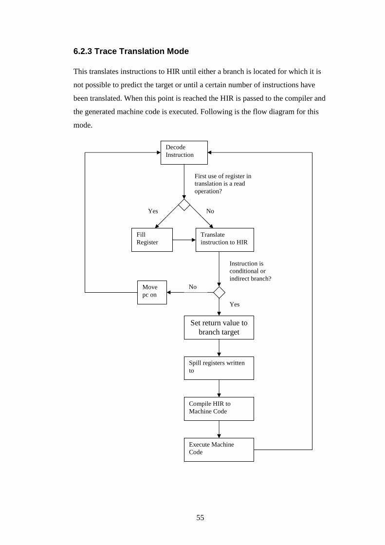
55
6.2.3 Trace Translation Mode This translates instructions to HIR until either a branch is located for which it is
not possible to predict the target or until a certain number of instructions have
been translated. When this point is reached the HIR is passed to the compiler and
the generated machine code is executed. Following is the flow diagram for this
mode.
Decode Instruction
First use of register in translation is a read operation?
No Yes
Fill Register
Translate instruction to HIR
Instruction is conditional or indirect branch?
Move pc on
No
Yes
Spill registers written to
Compile HIR to Machine Code
Execute Machine Code
Set return value to branch target
56
6.2.4 Structure
There are three components that control translation of x86 machine code to
native machine code. These are the classes X86_OptimisationPlanner,
X86_ConvertX86toHIR, MC2IR and X862IR.
X86_OptimisationPlanner is used to control the stages of the HIR to machine
code compiler. It specifies which translators to use at each stage.
X86_ConvertX86toHIR coordinates the x86 machine code to HIR translator with
the other stages, ensuring the generated HIR is in a form that is suitable for later
stages. X86_ConvertX86toHIR ensures X862IR gets used correctly.
MC2IR and X862IR control the translation itself. MC2IR handles the parts of the
translation that are not architecture specific such as method call planting,
controlling how the trace should be built. X862IR handles all architecture
specific operations such as using the correct instruction decoder/translator and
register handling.
6.2.5 Branch Handling
The x86 has three classes of branch. These are constant branch, conditional
branch and indirect branch.
A constant branch has the branch target encoded into the instruction. When the
translator finds this type of branch it continues from the branch target. It does not
add any HIR to the trace.
A conditional branch has the branch target encoded into the instruction, but
whether the branch is taken or not is decided by the state of the condition flags at
the time of the instructions execution. When the translator reaches this type of

57
branch, it inserts code to resolve the flag laziness and then code to return the next
instruction location based on that result. The translation then stops.
An indirect branch has a target stored in a specific register or memory location.
The branch will always be taken. When the translator reaches this type of branch,
code is inserted to resolve register the register if necessary, and then return the
branch target address. The retn instruction is classed as this type of branch.
6.2.6 Reusing HIR Quite often different traces will use instructions from the same memory location.
This is usually due to several branch instructions having the same target.
It is obviously inefficient to generate HIR which is identical to that previously
generated.
To solve this, a cache of previously generated HIR is kept in a hash map in the
class MC2IR. The current lazy state is used as the key.
Before each instruction is translated Pearcolator checks that the instruction has
not previously been translated with the same lazy state. If the instruction
translation is found in the cache then the cached translation is linked into the
current trace. The translation can then end. This is because all translated
instructions after the cached instruction are linked into the cached instruction so
the trace is complete.
If a suitable translation is not found in the cache the instruction is translated as
normal, and the translation is added to the cache.
6.2.7 Planting Method Calls It is often necessary for the translated HIR to make method calls. This is needed
for filling and spilling registers, making system calls and accessing memory.

58
It is fairly simple to make method calls from HIR. It is simply a matter of
specifying the object the method is in, the name of the method, the arguments to
use and where to put the return value.
Before a method can be called it must be compiled and useable by the generated
HIR. To ensure this the class DummyDynamicCodeRunner was created. It
contains method calls to all methods that can be planted. It is referenced by parts
of the code translator and ensures each method is compiled into a form useable
by the translated code. It is possible to dynamically compile methods but tends to
be messy so this feature is not used.
6.2.8 Compilation Once a trace has been converted to HIR it is time to compile it to native machine
code.
Pearcolator has two compilers i.e. the baseline and adaptive compilers.
The baseline compiler compiles to native machine code as quickly as possible. It
performs only minimal optimisations. For this reason the code it generates tends
to be fairly inefficient. It does have the advantage of compiling quickly.
The adaptive compiler is an optimising compiler. It has many levels of
optimisation. The more that a piece of code is executed the more heavily it is
optimised. For this reason it tends to generate efficient code. Unfortunately, the
compiler tends to be slower.
Pearcolator uses the optimising compiler. This is because Pearcolator is designed
primarily for emulating long running programs such as web servers or databases.
As such, any machine code generated will be executed many times. Any
deficiencies will impact performance considerably. Due to the nature of the

59
programs to be emulated any extra time spent compiling is offset by the overall
speed increase in the execution of the program.
By default, Pearcolator sets the initial optimisation level to 0. When code is
executed it gets profiled by Jikes RVM. When warranted Jikes RVM can
increase the optimisation level of a trace. This results in the trace being
recompiled with the extra optimisations.
For this to work Pearcolator must cache traces that have been compiled. The
cache stores VM_CodeArray objects which contains translated machine code.
Note that this cache of compiled HIR (i.e. machine code) is different to the cache
of emulated machine code converted to HIR mentioned EARLIER.
Before translation of a trace into HIR starts Pearcolator checks the cache of
compiled traces to ensure a trace will not be retranslated.
6.2.9 Execution Once a trace has been compiled it must be executed. This is accomplished by
passing the VM_CodeArray object associated with the trace to the method
VM_Magic.dynamicBridgeTo.
6.3 Interpretation
6.3.1 Introduction Although the primary role of Pearcolator is to emulate long running programs it
was felt desirable that performance should be improved for short running
programs.
With code translation the generated HIR must pass through several stages of
compilation and optimisation. This produces fast code but makes the compiler
relatively slow. Even if a block of code is only to be executed once it must still

60
pass through the same compiler as code that is executed several million times. If
a program will only run for a few seconds a considerable amount of time will
still be spent on compilation.
By only running the adaptive compiler on parts of the program that execute
frequently it is hoped the execution time of short lived programs can be
significantly reduced.
6.3.2 Operation of the Interpreter
Once an instruction has been decoded (instruction decoding is covered in the
next chapter) it is then executed immediately without passing through a compiler.
The operation of the instruction to be emulated is implemented in a method that
is called after the instruction has been decoded.
As an example, the method that implements adding two integers is the following:
int interpret(int pc, int nextPc, ProcessSpace ps,
IntOperand op1, IntOperand op2) {
op1.write(ps, op1.read(ps) + op2.read(ps);
return nextPc;
}
6.3.4 Switching from Interpretation to Code Translation Pearcolator must know at what point in the execution of a program it is suitable
to stop interpreting a section of code and instead translate it to machine code. A
simple way is to count the number of times an instruction at an address is
interpreted. Once the instruction has been executed a certain number of times,
invoke the code translator. This is the current behaviour of Pearcolator.
Although the current behaviour works as it should, keeping track of every
instruction carries a lot of overhead which slows down the performance
considerably.

61
A better system is to ignore how many times an individual instruction has been
executed and make the decision to switch at a branch. When interpreting a
branch, Pearcolator should keep track of how many times the target has been
branched to. When a target has been branched to a certain number of times then
it should be translated.
This technique has a number of benefits:
1 Less overhead for the interpreter.
2 Allows certain optimisations in the instruction decoder.
3 Ensures translated traces start at a branch target and end at a branch. This
keeps the traces similar to methods in Java. It is hoped in the future
Pearcolator may output Java bytecode so that emulated programs may be
executed on other Java Virtual Machines.
Another technique that has only received minimal research up to now is to use
Compiler DNA. Compiler DNA is the system used by the adaptive compiler in
Jikes RVM to decide when the next level of optimisation should be applied. It
works by keeping track of how long an optimisation will take to apply and how
much of an improvement is likely. If the length of time to perform the
optimisation is not offset be the improvement in speed no optimisation is applied.
6.4 Improving the Translator The code translator currently has a problem with branch handling. When the
translator reaches a conditional or an indirect branch a decision must be made as
to which instruction to decode next. Either the translation can halt with the
generated code returning the address of the next instruction to be executed, or the
translator can translate all possible branch targets. Currently Pearcolator uses the
former technique.
With the introduction of an interpreter it becomes possible to profile the branches
before translation. This allows Pearcolator to detect which branch targets are

62
used most so they can be translated. All other branch targets can continue to be
interpreted.
6.5 Status of Interpreter Unfortunately the current functionality of the interpreter is behind the translator.
Whereas the translator is able to handle fairly substantial programs, the
interpreter is missing some vital feature such as conditional branching.
Lack of conditional branching in the interpreter has also impacted the translator.
The branch handling of the translator was built to ensure easy addition of
profiled branching in the future. It was hoped that it would then be possible to
put an if instruction at the branch. If either of the branch targets had been
interpreted enough times or had been previously translated the translation could
continue. For any branch targets for which this is not the case the translation
would finish.
However, the interpreter has not reached a point which allows this. Currently
when the translator reaches a conditional or indirect branch, translation halts. It
should be a simple but time consuming matter to add the required functionality to
the interpreter.
63
7 Current Status and The Future of x86 Pearcolator
7.1 Current Status
The x86 version of Pearcolator is not as advanced as the PowerPC version. The
PowerPC version can run many benchmarks, substantial programs and is
currently under development to run Linux under emulation.
The x86 version can run substantial assembly programs. It can handle simple
programs written in C making use of glibc. Programs written using glibc tend to
be good tests that an emulator is working correctly. The following features of
Pearcolator have been tested by emulating simple glibc programs:
• The memory system
• Binary Loading
• Stack Layout
• The decoder
• Instruction translation
• Lazy register handling
• Lazy flag handling
• System calls
All features tested above have been found to work correctly. To get x86
Pearcolator to execute more complex programs is a matter of simply
implementing the instructions and system calls that are missing. The interpreter
has been tested on small assembly language programs and seems to work
adequately for the parts that are implemented.

64
7.2 The future of x86 Pearcolator
As work on Pearcolator is ongoing it seems useful to describe some of the future
advances that should be possible. Many of these have already been mentioned
throughout the dissertation, but will be summarised here for clarity.
7.2.1 Completing Instruction Set and System Calls
Only a small fraction of all the instructions and system calls are currently
implemented. The decoder is currently able to decode most instructions. The
instructions are merely missing translations and interpretations.
7.2.2 Dynamic Linking
Pearcolator for the x86 only handles statically linked binaries at present. Most
programs use dynamic linking. It is unknown how much work will be required to
enable dynamic linking.
7.2.3 Parallelisation
One of the benefits of Jikes RVM is that it allows use of multi processor
architectures. Pearcolator does not currently take advantage of this.
7.2.4 The Decoder
The Decoder currently works but as mentioned in section 5.5 could be made
faster with a few simple changes.

65
7.2.5 Native Memory
The memory system could be made a lot faster if JNI was used to access the
memory. This will avoid several mask and shift instructions being generated for
each memory access, replacing them with a single pointer manipulation.

66
References [1] Ian Rogers, Richard Matley, and Ian Watson. Dynamic binary translation
with a Java Virtual Machine. Submitted to 2005 International Symposium on
Code Generation and Optimization, 2004.
[2] Raymond J. Hookway, Mark A. Herdeg. Digital FX!32: Combining
Emulation and Binary Translation. Digigital Technical Journal Vol. 9 No. 1 1997
[3] IA-32 Intel Architecture Software Developer’s Manual Volumes 2A and 2B.
2005
[4] Steve Heller. Efficient C/C++ Programming. Academic Press, 1995.
[5] The Jamaica Project. http://www.cs.man.ac.uk/apt/projects/jamaica/.
[6] QEMU. http://fabrice.bellard.free.fr/qemu.
[7] Bochs. http://bochs.sourceforge.net.
[8] libdisasm. http://bastard.sourceforge.net.
[9] Sled. http://www.eecs.harvard.edu/~nr/toolkit/
[10] ndisasm. http://nasm.sourceforge.net
[11] Richard Blum. Professional Assembly Language. Wrox, 2005.
[12] Richard Matley. Native Code Execution within a JVM. MSc Thesis, The
University of Manchester, 2004
[13] ELF man page on Unix systems.