Embed Size (px)
Citation preview

QP state machine frameworks for ARM7/ARM9 with GNU
Application NoteQP™ and ARM7/9 with GNU
Document Revision IMarch 2014
Copyright © Quantum Leaps, LLC
www.quantum-leaps.com www.state-machine.com

Copyright © Quantum Leaps, LLC. All Rights Reserved.
Table of Contents1 Introduction ..................................................................................................................................................... 2
1.1 About the ARM Port ................................................................................................................................... 31.2 What’s Included in the Accompanying Code .............................................................................................. 41.3 About QP™ ................................................................................................................................................ 41.4 About QM™ ............................................................................................................................................... 51.5 Licensing QP .............................................................................................................................................. 61.6 Licensing QM™ .......................................................................................................................................... 6
2 Directories and Files ....................................................................................................................................... 72.1 Building the QP Libraries ............................................................................................................................ 82.2 Building the Examples ................................................................................................................................ 92.3 Downloading to Flash and Debugging the Examples ................................................................................. 13
3 Startup Code and Low-Level Initialization .................................................................................................... 193.1 Startup Code in Assembly .......................................................................................................................... 193.2 Low-Level Initialization ............................................................................................................................... 23
4 The Linker Script ............................................................................................................................................. 264.1 Linker Options ............................................................................................................................................ 30
5 C/C++ Compiler Options and Minimizing the Overhead of C++ .................................................................. 315.1 Compiler Options for C ............................................................................................................................... 315.2 Compiler Options for C++ ........................................................................................................................... 325.3 Reducing the Overhead of C++ .................................................................................................................. 32
6 The Vanilla Port ............................................................................................................................................... 346.1 The QF Port Header File ............................................................................................................................ 346.2 Handling Interrupts ..................................................................................................................................... 386.3 Idle Loop Customization in the “Vanilla” Port ............................................................................................. 47
7 The QK Port ..................................................................................................................................................... 497.1 Compiler and Linker Options Used ............................................................................................................. 497.2 The QK Port Header File ............................................................................................................................ 497.3 Handling Interrupts ..................................................................................................................................... 497.4 Idle Loop Customization in the QK Port ..................................................................................................... 52
8 Fine-tuning the Application ............................................................................................................................ 538.1 Controlling Placement of the Code in Memory ........................................................................................... 538.2 Controlling ARM/THUMB Compilation ........................................................................................................ 53
9 References ....................................................................................................................................................... 54
10 Contact Information ...................................................................................................................................... 55
1 of 55

Copyright © Quantum Leaps, LLC. All Rights Reserved.
Application NoteQP™ and ARM7/ ARM9 with GNU
www.state-machine.com/arm
1 IntroductionThis Application Note describes how to use the QP/C™ and QP™/C++ frameworks version 5.2.1 or higher on the ARM7 or ARM9 processors with the GNU toolchain. This document describes the following two main implementation options:
1. The cooperative “Vanilla” kernel; and
2. The preemptive run-to-completion QK™ kernel.
The provided application examples illustrate also using the QM™ modeling tool for designing QP applications graphically and generating code automatically.
Figure 1: AT91SAM7S-EK evaluation board from Atmel and the J-Link pod
This Application Note uses the open source devkitPro GNU-ARM toolset available from https://sourceforge.net/projects/devkitpro/files/devkitARM [devkitARM]. This Application Note covers building and debugging ARM projects with the GNU toolchain and with Eclipse.
NOTE: This Application Note pertains both to C and C++ versions of the QP™ state machine frameworks. Most of the code listings in this document refer to the QP/C version. Occasionally the C code is followed by the equivalent C++ implementation to show the C++ differences whenever such differences become important.
2 of 55
J-LinkJ-TAG pod
4 LEDs
AtmelAT91SAM7S64
device
external power
QSPY output(NULL-modemcable to PC)
Standard 20-pinJ-TAG connector

Copyright © Quantum Leaps, LLC. All Rights Reserved.
Application NoteQP™ and ARM7/ ARM9 with GNU
www.state-machine.com/arm
This Application Note uses the AT91SAM7S-EK development board from Atmel as an example hardware platform. The actual hardware/software used is as follows:
1. QP/C or QP/C++ version 5.2.1 or higher available from www.state-machine.com/downloads.
2. The devkitARM GNU-ARM toolset available from SourceForge.net at https://sourceforge.net/projects/devkitpro/files/devkitARM [devkitARM]
3. The GNU make 3.82 and related UNIX-file utilities for Windows available from the Qtools collection at http://www.state-machine.com/downloads [Qtools for Windows]
4. Insight GDB frontend available from SourceForge.net at https://sourceforge.net/projects/devkitpro/files/Insight [Insight-GDB].
5. Eclipse IDE for C/C++ Developers available from http://www.eclipse.org/downloads [Eclipse] with Zylin Embedded CDT plugin available from http://opensource.zylin.com/embeddedcdt.html [Zylin-pugin] to improve support for the GDB embedded debugging with Eclipse.
6. AT91SAM7S-EK evaluation board from Atmel (AT91SAM7S64 MCU)
7. SEGGER J-Link ARM J-TAG pod available from www.segger.com with SEGGER J-Link GDB Server software v4.08l available for download from www.segger.com/cms/downloads.html
1.1 About the ARM Port
The ARM core is a quite complicated processor in that it supports two operating states: ARM state, which executes 32-bit, word-aligned ARM instructions, and THUMB state, which operates with 16-bit, halfword-aligned THUMB instructions. On top of this, the CPU has several operating modes, such as USER, SYSTEM, SUPERVISOR, ABORT, UNDEFINED, IRQ, and FIQ. Each of these operating modes differs invisibility of registers (register banking) and sometimes privileges to execute instructions.
All these options mean that a designer must make several choices about the use of the ARM processor. This Application Note makes the following choices and assumptions:
2. The ARM processor executes in both ARM and THUMB states, meaning that some parts of the code are compiled to ARM and others to THUMB instruction sets, and calls between ARM and THUMB functions are allowed. Such approach is supported by the “interwork” option of the ARM compilers and linkers. This choice is optimal for most ARM-based microcontrollers, where large parts of the code execute from slower Flash ROM that in many cases is only 16-bit wide. The higher code densityof the THUMB instruction set in such cases improves performance compared to ARM, even though THUMB is a less powerful instruction set.
3. The ARM processor operates in the SYSTEM mode (CPSR[0:4] = 0x1F) while processing task-levelcode, and briefly switches to the IRQ mode (CPSR[0:4] = 0x12) or FIQ mode (CPSR[0:4] = 0x11) to process IRQ or FIQ interrupts, respectively. The System mode is used for its ability to execute the MSR/MRS instructions necessary to quickly disable and enable interrupts. NOTE: The SYSTEM mode is the default mode assumed by many compilers for execution of applications.
4. The ARM processor uses only single stack (the USER/SYSTEM stack) for all tasks, interrupts, and exceptions. The private (banked) stack pointers in SUPERVISOR, ABORT, UNDEFINED, IRQ, and FIQ modes are used only as working registers, but not to point to the private stacks. This means that you don’t need to allocate any RAM for the SUPERVISOR, ABORT, UNDEFINED, IRQ, or the FIQ stacks and you don’t need to initialize these stack pointers. The only stack you need to allocate and initialize is the USER/SYSTEM stack.
5. The interrupt disabling policy includes disabling only the IRQ and leaves the FIQ enabled. Consequently, the application can use only the IRQ for processing of general-purpose interrupts.
6. The FIQ is treated as a Non-Maskable Interrupt and cannot call any QP services. (NOTE: please refer to the QP-ARM-IAR implementation, if you wish to handle FIQ as a general-purpose interrupt.)
3 of 55

Copyright © Quantum Leaps, LLC. All Rights Reserved.
Application NoteQP™ and ARM7/ ARM9 with GNU
www.state-machine.com/arm
1.2 What’s Included in the Accompanying Code
The code accompanying this Application Note contains the separate C and C++ example, each containing the standard startup code, linker script, makefiles, board support package (BSP) and two versions of the Dining Philosopher Problem (DPP) example for two different kernels available in QP. The DPP application is described in Chapter 7 of [PSiCC2] as well as in the Application Note “Dining Philosopher Problem” [QL AN-DPP 08] (included in the QDK distribution).
1.3 About QP™
QP™ is a family of very lightweight, open source, state machine-basedframeworks for developing event-driven applications. QP enables buildingwell-structured embedded applications as a set of concurrently executinghierarchical state machines (UML statecharts) directly in C or C++, evenwithout big code-synthesizing tools. QP is described in great detail in thebook “Practical UML Statecharts in C/C++, Second Edition: Event-DrivenProgramming for Embedded Systems” [PSiCC2] (Newnes, 2008).
As shown in Figure 2, QP consists of a universal UML-compliant eventprocessor (QEP), a portable real-time framework (QF), a tiny run-to-completion kernel (QK), and software tracing instrumentation (QS). Currentversions of QP include: QP/C™ and QP/C++™, which require about 4KB ofcode and a few hundred bytes of RAM, and the ultra-lightweight QP-nano,which requires only 1-2KB of code and just several bytes of RAM.
Figure 2: QP components and their relationship with the target hardware, board support package(BSP), and the application
QP can work with or without a traditional RTOS or OS. In the simplest configuration, QP can completely replace a traditional RTOS. QP includes a simple non-preemptive scheduler and a fully preemptive kernel (QK). QK is smaller and faster than most traditional preemptive kernels or RTOS, yet offers fully deterministic, preemptive execution of embedded applications. QP can manage up to 63 concurrently executing tasks structured as state machines (called active objects in UML).
QP/C and QP/C++ can also work with a traditional OS/RTOS to take advantage of existing device drivers,communication stacks, and other middleware. QP has been ported to Linux/BSD, Windows, VxWorks, ThreadX, uC/OS-II, FreeRTOS.org, and other popular OS/RTOS.
4 of 55

Copyright © Quantum Leaps, LLC. All Rights Reserved.
Application NoteQP™ and ARM7/ ARM9 with GNU
www.state-machine.com/arm
1.4 About QM™
QM™ (QP™ Modeler) is a free, cross-platform, graphical UML modeling tool for designing and implementing real-time embedded applications basedon the QP™ state machine frameworks. QM™ itself is based on the Qt framework and therefore runs naively on Windows, Linux, and Mac OS X.
QM™ provides intuitive diagramming environment for creating good looking hierarchical state machine diagrams and hierarchical outline of your entire application. QM™ eliminates coding errors by automatic generation of compact C or C++ code that is 100% traceable from your design. Please visit state-machine.com/qm for more information about QM™.
The code accompanying this App Note contains three application examples:the Dining Philosopher Problem [AN-DPP], the PEdestrian LIght CONtrolled[AN-PELICAN] crossing, and the “Fly 'n' Shoot” game simulation for the EK-LM3S811 board (see Chapter 1 in [PSiCC2] all modeled with QM.
NOTE: The provided QM model files assume QM version 2.2.03 or higher.
Figure 3: The PELICAN example model opened in the QM™ modeling tool
5 of 55

Copyright © Quantum Leaps, LLC. All Rights Reserved.
Application NoteQP™ and ARM7/ ARM9 with GNU
www.state-machine.com/arm
1.5 Licensing QP
The Generally Available (GA) distribution of QP™ available for download from the www.state-machine.com/ downloads website is offered with the following two licensing options:
• The GNU General Public License version 2 (GPL) as published by the FreeSoftware Foundation and appearing in the file GPL.TXT included in the packaging ofevery Quantum Leaps software distribution. The GPL open source license allowsyou to use the software at no charge under the condition that if you redistribute theoriginal software or applications derived from it, the complete source code for yourapplication must be also available under the conditions of the GPL (GPL Section2[b]).
• One of several Quantum Leaps commercial licenses, which are designed forcustomers who wish to retain the proprietary status of their code and therefore cannotuse the GNU General Public License. The customers who license Quantum Leapssoftware under the commercial licenses do not use the software under the GPL andtherefore are not subject to any of its terms.
For more information, please visit the licensing section of our website at: www.state-machine.com/licensing
1.6 Licensing QM™
The QM™ graphical modeling tool available for download from the www.state-machine.com/ downloads website is free to use, but is not open source. During the installation you will need to accept a basic End-User License Agreement (EULA), which legally protects Quantum Leaps from any warranty claims, prohibits removing any copyright notices from QM, selling it, and creating similar competitive products.
6 of 55
Copyright © Quantum Leaps, LLC. All Rights Reserved.
Application NoteQP™ and ARM7/ ARM9 with GNU
www.state-machine.com/arm
2 Directories and FilesThe code for the QP port to ARM is available as part of any QP Development Kit (QDK) for ARM. The QDKs assume that the generic platform-independent QP™ distribution has been installed.
The code of the ARM port is organized according to the Application Note: “QP_Directory_Structure”. Specifically, for this port the files are placed in the following directories:
Listing 1 Selected Directories and files of the QP after installing the QDK-ARM-GNU. Directoriesand files shown in bold indicate the elements included in the ARM port.
<qp>/ - QP/C or QP/C++ Root Directory | +-include/ - QP public include files | +-qassert.h – Quantum Assertions platform-independent public include | +-qevent.h – QEvent declaration | +-qep.h – QEP platform-independent public include | +-qf.h – QF platform-independent public include | +-qk.h – QK platform-independent public include | +-qs.h – QS platform-independent public include | +-qs_dummy.h – QS “dummy” public include | +-qequeue.h – native QF event queue include | +-qmpool.h – native QF memory pool include | +-qpset.h – native QF priority set include | +-qvanilla.h – native QF non-preemptive “vanilla” kernel include | +-ports/ - QP ports | +-arm/ - ARM port | | +-vanilla/ - “vanilla” ports | | | +-gnu/ - GNU compiler | | | | +-dbg/ – Debug build | | | | | +-libqp__arm7tdmi.a – QP library for ARM7TDMI core | | | | +-rel/ – Release build | | | | | +-... – Release libraries | | | | +-spy/ – Spy build | | | | | +-... – Spy libraries | | | | +-src/ – Platfom-specific source directory | | | | | +-qf_port.s – Platfom-specific source code for the port | | | | +-make_arm7tdmi.bat – Batch script to build QP libraries for ARM7TDMI core | | | | +-. . . – Batch scripts to build QP libraries for other ARM cores | | | | +-qep_port.h – QEP platform-dependent public include | | | | +-qf_port.h – QF platform-dependent public include | | | | +-qs_port.h – QS platform-dependent public include | | | | +-qp_port.h – QP platform-dependent public include | | +-qk/ - QK (Quantum Kernel) ports | | | +-gnu/ - GNU compiler | | | | +-dbg/ – Debug build | | | | | +-libqp__arm7tdmi.a – QP library for ARM7TDMI core | | | | | | | | | +-rel/ – Release build | | | | | +-... – Release libraries | | | | +-spy/ – Spy build | | | | | +-... – Spy libraries | | | | +-src/ – Platfom-specific source directory | | | | | +-qk_port.s – Platfom-specific source code for the port
7 of 55

Copyright © Quantum Leaps, LLC. All Rights Reserved.
Application NoteQP™ and ARM7/ ARM9 with GNU
www.state-machine.com/arm
| | | | +-make_arm7tdmi.bat – Batch script to build QP libraries for ARM7TDMI core | | | | +-. . . – Batch scripts to build QP libraries for other ARM cores | | | | +-qep_port.h – QEP platform-dependent public include | | | | +-qf_port.h – QF platform-dependent public include | | | | +-qs_port.h – QS platform-dependent public include | | | | +-qp_port.h – QP platform-dependent public include | +-examples/ - QP examples | +-arm/ - ARM CPU | | +-vanilla/ - “Vanilla” port | | | +-gnu/ - GNU compiler | | | | +-.metadata - directory with Eclipse workspace | | | | +-dpp-at91sam7s-ek – DPP example for the AT91SAM7S-EK evaluation board | | | | | +-dbg/ – Debug build (runs from RAM) | | | | | | +-dpp.elf – executable image | | | | | +-rel/ – Release build (runs from Flash) | | | | | | +-dpp.elf – executable image | | | | | +-spy/ – Spy build (runs from RAM) | | | | | | +-dpp.elf – executable image (instrumented with QSpy) | | | | | +-Makefile – Makefile for the DPP application example | | | | | +-insight-jlink.bat– Batch file to launch the Insight with J-Link | | | | | +-jlink.dgb – GDB configuration file for J-Link | | | | | +-startup.s – startup code in assembly | | | | | +-low_level_init.c – low-level initialization in C | | | | | +-dpp.qm - QM Model of the DPP application | | | | | +-dpp.ld – GNU linker command file for the DPP application | | | | | +-bsp.h - Board Support Package include file | | | | | +-bsp.c - Board Support Package implementation | | | | | +-dpp.h - Source code of the DPP application | | | | | +-main.c - Source code of the DPP application | | | | | +-philo.c - Source code of the DPP application | | | | | +-table.c - Source code of the DPP applicationn | | | | | | +-qk/ - QK (Quantum Kernel) port | | | +-gnu/ - GNU compiler | | | | +-.metadata - directory with Eclipse workspace | | | | +-dpp-qk-at91sam7s-ek – DPP example for the AT91SAM7S-EK board with QK | | | | | +-. . . – the same files as in vanilla/gnu/dpp-at91sam7s | . . .
2.1 Building the QP Libraries
All QP components are deployed as libraries that you statically link to your application. The pre-built libraries for QEP, QF, QS, and QK are provided inside the <qp>\ports\ directory (see Listing 1).This section describes steps you need to take to rebuild the libraries yourself.
NOTE: To achieve commonality among different development tools, Quantum Leaps software does not use the vendor-specific IDEs, such as the IAR Embedded Workbench IDE, for building the QP libraries. Instead, QP supportscommand-line build process based on simple batch scripts.
The code distribution contains the batch file make_<core>.bat for building all the libraries located in the <qp>\ports\arm\... directory. For example, to build the debug version of all the QP libraries for the ARM7TDMI core, with the IAR ARM compiler, QK kernel, you open a console window on a Windows PC,
8 of 55

Copyright © Quantum Leaps, LLC. All Rights Reserved.
Application NoteQP™ and ARM7/ ARM9 with GNU
www.state-machine.com/arm
change directory to <qp>\ports\arm\qk\gnu\, and invoke the batch by typing at the command prompt the following command:
make_arm7tdmi.bat
The build process should produce the QP libraries in the location: <qp>\ports\arm\qk\gnu\dbg\. The make_<core>.bat files assume that the ARM GNU toolset has been installed in the directory C:\tools\devkitPro\devkitARM.
NOTE: You need to adjust the symbol GNU_ARM at the top of the batch scripts if you’ve installed the IAR ARM compiler into a different directory.
In order to take advantage of the QS (“spy”) instrumentation, you need to build the QS version of the QP libraries. You achieve this by invoking the make_<core>.bat utility with the “spy” target, like this:
make_arm7tdmi.bat spy
The make process should produce the QP libraries in the directory: <qp>\ports\arm\vanilla\gnu\-spy\.
You choose the build configuration by providing a target to the make_<core>.bat utility. The default targetis “dbg”. Other targets are “rel”, and “spy” respectively. The following table summarizes the targets accepted by make_<core>.bat.
Table 1 Make targets for the Debug, Release, and Spy software configurations
Software Version Build command
Debug (default) make_<core>
Release make_<core> rel
Spy make_<core> spy
2.2 Building the Examples
The examples included in this Application Note are based on the standard Dining Philosophers Problem implemented with active objects (see Chapter 9 in [PSiCC2] and the Application Note “Dining PhilosopherProblem Example” [AN-DPP] included in the QDK download).
2.2.1 The Makefile
Whichever way you'll choose to build the QP examples (command-line or Eclipse), you are going to use the same Makefile, provided in the directory <qp>\examples\arm\vanilla\gnu\dpp-at91sam7s-ek\. The most important part of this Makefile, which you need to customize for your own projects, is the files section. For the classic ARM architecture (ARM7/ARM9), the file section allows you to specify which modules are going to be compiled in ARM mode and which in the THUMB mode. This determination is quite important for achieving optimal performance. Generally interrupt processing and system-level code performs better when compiled to ARM, while the application-level code (e.g., state machines) perform better and take less codespace when compiled to THUMB. The following Listing 2 shows the “files” section of the Makefile.
9 of 55

Copyright © Quantum Leaps, LLC. All Rights Reserved.
Application NoteQP™ and ARM7/ ARM9 with GNU
www.state-machine.com/arm
Listing 2 The “files” section of the Makefile allows you to specifyfiles to be compiled to ARM and to THUMB
. . .#-----------------------------------------------------------------------------# files#
# assembler source filesASM_SRCS := $(wildcard *.s)
# C ARM source filesC_ARM_SRCS := isr.c bsp.c
# C THUMB source filesC_THUMB_SRCS := low_level_init.c main.c philo.c table.c
# C++ ARM source filesCPP_ARM_SRCS :=
# C++ THUMB source filesCPP_THUMB_SRCS :=
LD_SCRIPT := dpp-qk.ldLIBS := -lqp_$(ARM_CORE)
. . .
2.2.2 Building the Examples from Command Line
The example directory <qp>\examples\arm\vanilla\gnu\dpp-at91sam7s-ek\ contains the Makefile you can use to build the application. The Makefile supports three build configurations: Debug (default), Release, and Spy. You choose the build configuration by defining the CONF symbol at the command line, as shown in the table below. Figure 4 shows and example command-line build of the Spy configuration.
Table 2 Make targets for the Debug, Release, and Spy software configurations
Build Configuration Build command
Debug (default) make
Release make CONF=rel
Spy make CONF=spy
Clean the Debug configuration make clean
Clean the Release configuration make CONF=rel clean
Clean the Spy configuration make CONF=spy clean
10 of 55

Copyright © Quantum Leaps, LLC. All Rights Reserved.
Application NoteQP™ and ARM7/ ARM9 with GNU
www.state-machine.com/arm
Figure 4: Building the DPP application with the provided Makefile from command-line
2.2.3 Building the Examples from Eclipse
The example code contains the Eclipse workspaces and projects for building and debugging the DPP examples with the Eclipse IDE. The following screen shot shows how to open the provided workspace in Eclipse.
11 of 55

Copyright © Quantum Leaps, LLC. All Rights Reserved.
Application NoteQP™ and ARM7/ ARM9 with GNU
www.state-machine.com/arm
NOTE: The “How To” section of the YAGARTO website at http://www.yagarto.de/howto/yagarto2 provides a detailed tutorial for installing and configuring Eclipse for ARM development. You can create and configure the build configurations from the Project | Build Configurations | Manage… sub-menu. For the Release and Spy configurations,you should set the make command to make CONF=rel and make CONF=spy, respectively. The provided Makefile also correctly supports the clean targets, so invoking Project | Clean… menu for any build configuration works as expected.
The provided Eclipse projects are Makefile-type projects, which use the same Makefiles that you can call from the command line. In fact the Makefiles are specifically designed to allow building all supportedconfigurations from Eclipse, as shown in Figure 5.
12 of 55
Selecting a workspacein Eclipse
Point to the directorythat contains .metadata

Copyright © Quantum Leaps, LLC. All Rights Reserved.
Application NoteQP™ and ARM7/ ARM9 with GNU
www.state-machine.com/arm
Figure 5: Building the DPP application with the provided Makefile in Eclipse
2.3 Downloading to Flash and Debugging the Examples
You have several options for downloading and debugging the examples. The devkitPro project includes the Insight GDB front-end (https://sourceforge.net/projects/devkitpro/files/Insight [Insight-GDB]), which is perhaps the simplest way. The other option is to use Eclipse with the Zylin Embedded CDT plugin. Pleaserefer to the Zylin website at http://opensource.zylin.com/embeddedcdt.html for more information how to install the CDT plugin in Eclipse.
2.3.1 Starting the GDB Server
Regardless whether you use Insight, Eclipse, or even just the raw GDB, you would need a J-Tag pod and a GDB Server software. This Application Note uses the J-Link pod from SEGGER and the J-Link GDB Server software v4.08l available for download from www.segger.com/cms/downloads.html. However, you might just as well use other J-Tag pods and other GDB server software, such as OpenOCD (http://openocd.berlios.de).
You launch the J-Link GDB server by clicking on the JLinkGDBServer.exe application in the SEGGER directory.
NOTE: You need a license to run the J-Link GDB Server. SEGGER now offers free licenses for Non-Commercial-Use, see http://www.segger.com/cms/j-link-arm-for-non-commercial-use.html.
13 of 55
Selecting the build configuration
Console outputfrom the build
The Makefile used with Eclipse

Copyright © Quantum Leaps, LLC. All Rights Reserved.
Application NoteQP™ and ARM7/ ARM9 with GNU
www.state-machine.com/arm
Figure 6: SEGGER’s J-Link GDB Server
2.3.2 Downloading to Flash and Debugging with Insight
The example directory <qp>\examples\arm\vanilla\gnu\dpp-at91sam7s-ek\ contains the GDB command file jlink.gdb file as well as the insight-jlink.bat batch file to launch the Insight debugger.
Figure 7: Debugging the example application with Insight
14 of 55
J-Link GDB Server
Insight Console
Command Prompt to launch Insight
Various Insightview windows

Copyright © Quantum Leaps, LLC. All Rights Reserved.
Application NoteQP™ and ARM7/ ARM9 with GNU
www.state-machine.com/arm
To start debugging you can simply double-clink on the drom_jlink.bat batch file, which will launch the Insight debugger and load the dbg\dpp.elf image to the flash memory of the AT91SAM7S microcontroller. Figure 7 shows a screen shot from the Insight Debug session.
As the application is running, the status LEDs at the top of the board (see ) should blink indicating the changing status of the Dining Philosophers.
2.3.3 Downloading to Flash and Debugging with Eclipse
You can also use Eclipse to debug the DPP application. Configuring the Eclipse debugger is somewhat involved and requires a plugin to improve Embedded debugging with the Eclipse CDT. The YAGARTO website provides a step-by-step tutorial (see http://www.yagarto.de/howto/yagarto2/) of how to install Eclipse and the Zylin Embedded CDT plugin. The following discussion assumes that you have installed the Zylin plugin.
Figure 8 shows screen shots that illustrate how to open the Debug dialog box and configure a debug session in Eclipse. The Main tab of the Debug dialog box shows how the project is setup for debugging. The Debugger tab of the Debug dialog box shows how to configure the devkitPro debugger and the GDB command file. Here you use the same jlink.gdb GDB command file as for debugging with Insight, because you use the same J-Link GDB server shown in Figure 6.
15 of 55

Copyright © Quantum Leaps, LLC. All Rights Reserved.
Application NoteQP™ and ARM7/ ARM9 with GNU
www.state-machine.com/arm
Figure 8: Configuring the Debugger in Eclipse
16 of 55
Launching theDebug dialog box
Main tab of theDebug dialog box
Debugger tab of theDebug dialog box

Copyright © Quantum Leaps, LLC. All Rights Reserved.
Application NoteQP™ and ARM7/ ARM9 with GNU
www.state-machine.com/arm
The following screen shot shows a debugging session in Eclipse with various views. The SEGGER J-LinkGDB Server is shown in the lower-right corner of the screen.
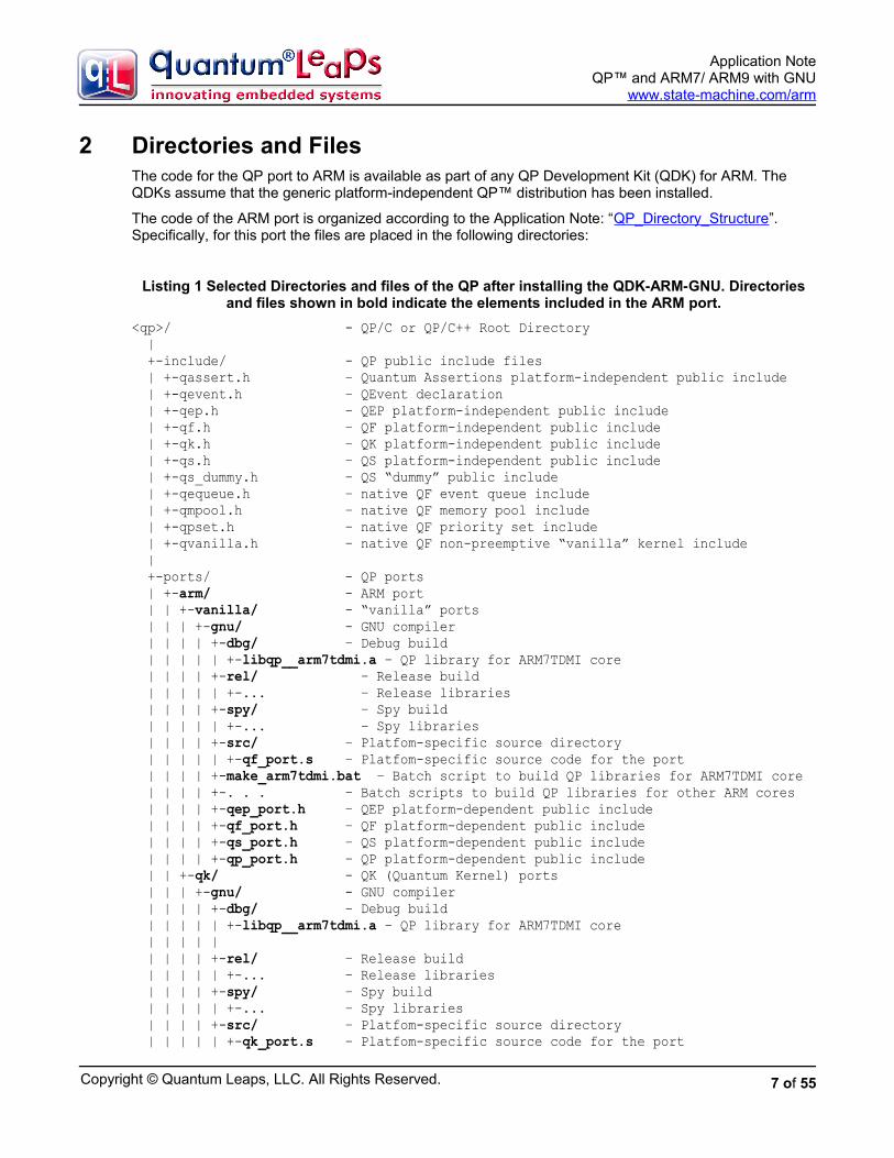
2.3.4 Software Tracing with Q-SPY
If you load the Spy configuration to the board and connect the serial NULL-cable to the DBGU DB9 connector and your PC, you could launch the QSPY host utility to observe the software trace output in thehuman-readable format. You launch the QSPY utility on a Windows PC open a command prompt and type (NOTE: the QSPY host utility is part of the Qtools collection available for download from www.state-machine.com/downloads/index.php#QTools ):
qspy –c COM1 –b 115200
17 of 55
Copyright © Quantum Leaps, LLC. All Rights Reserved.
Application NoteQP™ and ARM7/ ARM9 with GNU
www.state-machine.com/arm
Figure 9: Screen shot from the QSPY output
18 of 55

Copyright © Quantum Leaps, LLC. All Rights Reserved.
Application NoteQP™ and ARM7/ ARM9 with GNU
www.state-machine.com/arm
3 Startup Code and Low-Level InitializationThe application directory contains the generic startup code for the GNU toolchain (file startup.s) as well as the low-level initialization (low_level_init.c) for a bare-metal ARM system. This section covers these two files in detail.
3.1 Startup Code in Assembly
The startup sequence for a bare-metal ARM system is implemented in the assembly file startup.s, which is identical for C and C++ projects. This file is designed to be generic, and should work for any ARM-based MCU without modifications. All CPU- and board-specific low-level initialization that needs to occur before entering the main() function should be handled in the routine low_level_init(), which typically can be written in C/C++, but can also be coded in assembly, if necessary..
Listing 3: Startup code in GNU assembly (startup.s)
/***************************************************************************** * The startup code must be linked at the start of ROM, which is NOT * necessarily address zero. */(1) .text(2) .code 32
(3) .global _start(4) .func _start1
_start1:
/* Vector table * NOTE: used only very briefly until RAM is remapped to address zero */(5) B _reset /* Reset: relative branch allows remap */(6) B . /* Undefined Instruction */ B . /* Software Interrupt */ B . /* Prefetch Abort */ B . /* Data Abort */ B . /* Reserved */ B . /* IRQ */ B . /* FIQ */
/* The copyright notice embedded prominently at the beginning of ROM */(7) .string "Copyright (c) YOUR COMPANY. All Rights Reserved."(8) .align 4 /* re-align to the word boundary */
/***************************************************************************** * _reset */(9) _reset:
/* Call the platform-specific low-level initialization routine * * NOTE: The ROM is typically NOT at its linked address before the remap,
19 of 55

Copyright © Quantum Leaps, LLC. All Rights Reserved.
Application NoteQP™ and ARM7/ ARM9 with GNU
www.state-machine.com/arm
* so the branch to low_level_init() must be relative (position * independent code). The low_level_init() function must continue to * execute in ARM state. Also, the function low_level_init() cannot rely * on uninitialized data being cleared and cannot use any initialized * data, because the .bss and .data sections have not been initialized yet. */(10) LDR r0,=_reset /* pass the reset address as the 1st argument */(11) LDR r1,=_cstartup /* pass the return address as the 2nd argument */(12) MOV lr,r1 /* set the return address after the remap */(13) LDR sp,=__stack_end__ /* set the temporary stack pointer */(14) B low_level_init /* relative branch enables remap */
/* NOTE: after the return from low_level_init() the ROM is remapped * to its linked address so the rest of the code executes at its linked * address. */
(15) _cstartup: /* Relocate .fastcode section (copy from ROM to RAM) */(16) LDR r0,=__fastcode_load LDR r1,=__fastcode_start LDR r2,=__fastcode_end 1: CMP r1,r2 LDMLTIA r0!,{r3} STMLTIA r1!,{r3} BLT 1b
/* Relocate the .data section (copy from ROM to RAM) */(17) LDR r0,=__data_load LDR r1,=__data_start LDR r2,=_edata 1: CMP r1,r2 LDMLTIA r0!,{r3} STMLTIA r1!,{r3} BLT 1b
/* Clear the .bss section (zero init) */(18) LDR r1,=__bss_start__ LDR r2,=__bss_end__ MOV r3,#0 1: CMP r1,r2 STMLTIA r1!,{r3} BLT 1b
(19) /* Fill the .stack section */ LDR r1,=__stack_start__ LDR r2,=__stack_end__ LDR r3,=STACK_FILL 1: CMP r2,r2 STMLTIA r1!,{r3} BLT 1b
20 of 55

Copyright © Quantum Leaps, LLC. All Rights Reserved.
Application NoteQP™ and ARM7/ ARM9 with GNU
www.state-machine.com/arm
(20) /* Initialize stack pointers for all ARM modes */ MSR CPSR_c,#(IRQ_MODE | I_BIT | F_BIT) LDR sp,=__irq_stack_top__ /* set the IRQ stack pointer */
MSR CPSR_c,#(FIQ_MODE | I_BIT | F_BIT) LDR sp,=__fiq_stack_top__ /* set the FIQ stack pointer */
MSR CPSR_c,#(SVC_MODE | I_BIT | F_BIT) LDR sp,=__svc_stack_top__ /* set the SVC stack pointer */
MSR CPSR_c,#(ABT_MODE | I_BIT | F_BIT) LDR sp,=__abt_stack_top__ /* set the ABT stack pointer */
MSR CPSR_c,#(UND_MODE | I_BIT | F_BIT) LDR sp,=__und_stack_top__ /* set the UND stack pointer */
(21) MSR CPSR_c,#(SYS_MODE | I_BIT | F_BIT) LDR sp,=__c_stack_top__ /* set the C stack pointer */
/* Invoke all static C++ constructors (harmless in C) */(22) LDR r12,=__libc_init_array MOV lr,pc /* set the return address */ BX r12 /* the target code can be ARM or THUMB */
/* Enter the C/C++ code */(23) LDR r12,=main MOV lr,pc /* set the return address */ BX r12 /* the target code can be ARM or THUMB */
(24) SWI 0xFFFFFF /* cause exception if main() ever returns */
.size _start1, . - _start1 .endfunc
(25) .global _exit .func _exit _exit: BX lr .size _exit, . - _exit .endfunc
.end
Listing 3 shows the complete startup code in assembly. The highlights of the startup sequence are as follows:
(1) The .text directive tells GNU assembler (as) to assemble the following statements onto the end of the text subsection.
(2) The .code 32 directive selects the 32-bit ARM instruction set (the value 16 selects THUMB). The ARM core starts execution in the ARM state.
(3) The .global directive makes the symbol _start visible to the GNU linker (ld).
(4) The .func directive emits debugging information for the function _start. (The function definition must end with the directive .endfunc).
21 of 55

Copyright © Quantum Leaps, LLC. All Rights Reserved.
Application NoteQP™ and ARM7/ ARM9 with GNU
www.state-machine.com/arm
(5) Upon reset, the ARM core fetches the instruction at address 0x0, which at boot time must be mapped to a non-volatile memory (ROM). However, later the ROM might be remapped to a different address range by means of a memory remap operation. Therefore the code in ROM is typically linked to the final ROM location and not to the ROM location at boot time. This dynamic changing of the memory map has at least two consequences. First, the few initial instructions must be position-independent meaning that only PC-relative addressing can be used. Second, the initial vector table is used only very briefly and is replaced with a different vector table established in RAM.
(6) The initial vector table contains just endless loops (relative branches to self). This vector table is used only very briefly until it is replaced by the vector table in RAM. Should an exception occur during this transient, the board is most likely damaged and the CPU cannot recover by itself. A safety-critical device should have a secondary circuit (such as an external watchdog timer driven by a separate clock source) that would announce the condition to the user.
(7) It is always a good idea to embed a prominent copyright message close to the beginning of the ROMimage. You should customize this message for your company.
(8) Alignment to the word boundary is necessary after a string embedded directly in the code.
(9) The reset vector branches to this label.
(10) The r0 and r1 registers are used as the arguments of the upcoming call to the low_level_init() function. The register r0 is loaded with the linked address of the reset handler, which might be usefulto set up the RAM-based vector table inside the low_level_init() function.
(11) The r1 register is loaded with the linked address of the C-initialization code, which also is the return address from the low_level_init() function. Some MCUs (such as AT91x40 with the EBI) might need this address to perform a direct jump after the memory remap operation.
(12) The link register is loaded with the return address. Please note that the return address is the _cstartup label at its final linked location, and not the subsequent PC value (so loading the return address with LDR lr,pc would be incorrect.)
(13) The temporary stack pointer is initialized to the end of the stack section. The GNU toolset uses the full descending stack meaning that the stack grows towards the lower memory addresses.
NOTE: The stack pointer initialized in this step might be not valid in case the RAM is not available at the linked address before the remap operation. It is not an issue in the AT91SAM7S family, because the RAM is always available at the linked address (0x00200000). However, in other devices (such as AT91x40) the RAM is not available at its final location before the EBI remap. In this latter case you might need to writhe the low_level_init() function in assembly to make sure that the stack pointer is not used until the memory remap.
(14) The function low_level_init() is invoked with a relative branch instruction. Please note that the branch-with-link (BL) instruction is specifically NOT used because the function might be called not from its linked address. Instead the return address has been loaded explicitly in the previous instruction.
NOTE: The function low_level_init() can be coded in C/C++ with the following restrictions. The function must execute in the ARM state and it must not rely on the initialization of .data section or clearing of the .bss section. Also,if the memory remapping is performed at all, it must occur inside the low_level_init() function because the code isno longer position-independent after this function returns.
(15) The _cstartup label marks the beginning of C-initialization.
(16) The section .fastcode is used for the code executed from RAM. Here this section is copied from ROM to its linked address in RAM (see also the linker script).
22 of 55
Copyright © Quantum Leaps, LLC. All Rights Reserved.
Application NoteQP™ and ARM7/ ARM9 with GNU
www.state-machine.com/arm
(17) The section .data is used for initialized variables. Here this section is copied from its load address inROM to its linked address in RAM (see also the linker script).
(18) The section .bss is used for uninitialized variables, which the C standard requires to be set to zero. Here this section is cleared in RAM (see also the linker script).
(19) The section .stack is used for the stacks. Here this section is filled with the given pattern, which canhelp to determine the stack usage in the debugger.
(20) All banked stack pointers are initialized.
(21) The User/System stack pointer is initialized last. All subsequent code executes in the System mode.
(22) The library function __libc_init_array invokes all C++ static constructors (see also the linker script). This function is invoked with the BX instruction, which allows state change to THUMB. This function is harmless in C.
(23) The main() function is invoked with the BX instruction, which allows state change to THUMB.
(24) The main() function should never return in a bare-metal application because there is no operating system to return to. In case main() ever returns, the Software Interrupt exception is entered, in which the user can customize how to handle this problem.
(25) The _exit function is invoked by the standard C library, but in a bare-metal system it is unused because the application never exits.
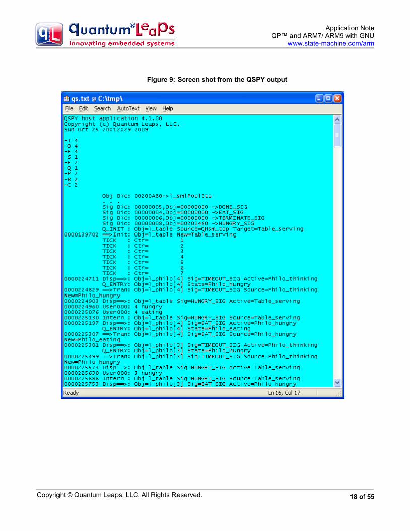
3.2 Low-Level Initialization
The function low_level_init() performs the low-level initialization, which always strongly depends on the specific ARM MCU and the particular memory remap operation. As described in the previous section, the function low_level_init() can be coded in C or C++, but must be compiled to ARM and cannot relyon the initialization of the .data section, clearing of the .bss section, or on C++ static constructors being called.
Listing 4: Low-level initialization for AT91SAM7S microcontroller
(1) #include <stdint.h> /* C-99 standard exact-width integer types */
(2) void low_level_init(void (*reset_addr)(), void (*return_addr)()) {(3) extern uint32_t __ram_start;(4) static uint32_t const LDR_PC_PC = 0xE59FF000U;(5) static uint32_t const MAGIC = 0xDEADBEEFU; AT91PS_PMC pPMC;
/* Set flash wait sate FWS and FMCN */(6) AT91C_BASE_MC->MC_FMR = ((AT91C_MC_FMCN) & ((MCK + 500000)/1000000 << 16)) | AT91C_MC_FWS_1FWS;(7) AT91C_BASE_WDTC->WDTC_WDMR = AT91C_WDTC_WDDIS; /* Disable the watchdog */
(8) /* Enable the Main Oscillator */ . . . /* Set the PLL and Divider and wait for PLL stabilization */. . . /* Select Master Clock and CPU Clock select the PLL clock / 2 */. . .
/* Setup the exception vectors in RAM. * NOTE: the exception vectors must be in RAM *before* the remap * in order to guarantee that the ARM core is provided with valid vectors * during the remap operation. */ /* setup the primary vector table in RAM */
23 of 55

Copyright © Quantum Leaps, LLC. All Rights Reserved.
Application NoteQP™ and ARM7/ ARM9 with GNU
www.state-machine.com/arm
(9) *(&__ram_start + 0) = (LDR_PC_PC | 0x18); *(&__ram_start + 1) = (LDR_PC_PC | 0x18); *(&__ram_start + 2) = (LDR_PC_PC | 0x18); *(&__ram_start + 3) = (LDR_PC_PC | 0x18); *(&__ram_start + 4) = (LDR_PC_PC | 0x18);(10) *(&__ram_start + 5) = MAGIC; *(&__ram_start + 6) = (LDR_PC_PC | 0x18); *(&__ram_start + 7) = (LDR_PC_PC | 0x18);
/* setup the secondary vector table in RAM */(11) *(&__ram_start + 8) = (uint32_t)reset_addr; *(&__ram_start + 9) = 0x04U; *(&__ram_start + 10) = 0x08U; *(&__ram_start + 11) = 0x0CU; *(&__ram_start + 12) = 0x10U; *(&__ram_start + 13) = 0x14U; *(&__ram_start + 14) = 0x18U; *(&__ram_start + 15) = 0x1CU;
/* check if the Memory Controller has been remapped already */(12) if (MAGIC != (*(uint32_t volatile *)0x14)) {(13) AT91C_BASE_MC->MC_RCR = 1; /* perform Memory Controller remapping */ }(14) }
Listing 4 shows the low-level initialization of the AT91SAM7S microcontroller in C. Note that the initialization for a different microcontroller, such as AT91x40 series with the EBI, could be different mostly due to different memory remap operation. The highlights of the low-level initialization are as follows:
(1) The GNU GCC is a standard-compliant compiler that supports the C-99 standard exact-width integertypes. The use of these types is recommended.
(2) The arguments of low_level_init() are as follows: reset_addr is the linked address of the reset handler and return_addr is the linked return address from the low_level_init() function.
NOTE: In the C++ environment, the function low_level_init() must be defined with the extern “C” linkage specification because it is called from assembly.
(3) The symbol __ram_start denotes the linked address of RAM. In AT91SAM7S the RAM is always available at this address, so the symbol __ram_start denotes also the RAM location before the remap operation (see the linker script).
(4) The constant LDR_PC_PC contains the opcode of the ARM instruction LDR pc,[pc,...], which is used to populate the RAM vector table.
(5) This constant MAGIC is used to test if the remap operation has been performed already.
(6) The number of flash wait states is reduced from the default value set at reset to speed up the boot process.
(7) The AT91 watchdog timer is disabled so that it does not expire during the boot process. The application can choose to enable the watchdog after the main() function is called.
(8) The CPU and peripheral clocks are configured. This speeds up the rest of the boot process.
(9) The ARM vector table is established in RAM before the memory remap operation, so that the ARM core is provided with valid vectors at all times. The vector table has the following structure:
24 of 55

Copyright © Quantum Leaps, LLC. All Rights Reserved.
Application NoteQP™ and ARM7/ ARM9 with GNU
www.state-machine.com/arm
0x00: LDR pc,[pc,#0x18] /* Reset */0x04: LDR pc,[pc,#0x18] /* Undefined Instruction */0x08: LDR pc,[pc,#0x18] /* Software Interrupt */0x0C: LDR pc,[pc,#0x18] /* Prefetch Abort */0x10: LDR pc,[pc,#0x18] /* Data Abort */0x14: LDR pc,[pc,#0x18] /* Reserved */0x18: LDR pc,[pc,#0x18] /* IRQ vector */0x1C: LDR pc,[pc,#0x18] /* FIQ vector */
All entries in the RAM vector table load the PC with the address located in the secondary jump table that immediately follows the primary vector table in memory. For example, the Reset exception at address 0x00 loads the PC with the word located at the effective address: 0x00 (+8 for pipeline) +0x18 = 0x20, which is the address immediately following the ARM vector table.
NOTE: Some ARM MCUs, such as the NXP LPC family, remap only a small portion of RAM down to address zero. However, the amount of RAM remapped is always at least 0x40 bytes (exactly 0x40 bytes in case of LPC), which is big enough to hold both the primary vector table and the secondary jump table.
(10) The jump table entry for the unused exception is initialized with the MAGIC number. Please note thatthis number is written to RAM at its location before the memory remap operation.
(11) The secondary jump table in RAM is initialized to contain jump to reset_addr at 0x20 and endless loops for the remaining exceptions. For example, the Prefetch Abort exception at address 0x0C will cause loading the PC again with 0x0C, so the CPU will be tied up in a loop. This is just the temporary setting until the application initializes the secondary jump table with the addresses of the application-specific exception handlers. Until this happens, the application is not ready to handle the interrupts or exceptions, anyway.
NOTE: Using the secondary jump table has many benefits. First, the application can very easily change the exceptionhandler by simply writing the handler’s address in the secondary table, rather than synthesize a relative branch instruction at the primary vector table. Second, the load to PC instruction allows utilizing the full 32-bit address space for placement of the exception handlers, whereas the relative branch instruction is limited to +/- 25 bits relative to the current PC.
(12) The word at the absolute address 0x14 is loaded and compared to the MAGIC number. The location 0x14 is in ROM before the remap operation, and is in RAM after the remap operation. Before the remap operation the location 0x14 contains the B . instruction, which is different from the MAGIC value.
(13) If the location 0x14 does not contain the MAGIC value, this indicates that the write to RAM did not change the value at address 0x14. This, in turn, means that RAM has not been remapped to address0x00 yet (i.e., ROM is still mapped to the address 0x00). In this case the remap operation must be performed.
NOTE: The AT91SAM7 Memory Controller remap operation is a toggle and it is impossible to detect whether the remap has been performed by examining any of the Memory Controller registers. The technique of writing to the low RAM address can be used to reliably detect whether the remap operation has been performed to avoid undoing it. This safeguard is very useful when the reset is performed during debugging. The soft-reset performed by a debugger typically does not undo the memory remap operation, so the remap should not be performed in this case.
(14) The low_level_init() function returns to the address set by the startup code in the lr register. Please note that at this point the code starts executing at its linked address.
25 of 55

Copyright © Quantum Leaps, LLC. All Rights Reserved.
Application NoteQP™ and ARM7/ ARM9 with GNU
www.state-machine.com/arm
4 The Linker ScriptThe linker script must match the startup code for all the section names and other linker symbols. The linker script cannot be generic, because it must define the specific memory map of the target device, as well as other application-specific information. The linker script therefore named here dpp.ld, which corresponds to the DPP example application.
Listing 5: Linker script for the DPP example application (AT91SAM7S64 MCU)
(1) OUTPUT_FORMAT("elf32-littlearm", "elf32-bigarm", "elf32-littlearm") (2) OUTPUT_ARCH(arm) (3) ENTRY(_vectors)
(4) MEMORY { /* memory map of AT91SAM7S64 */ (5) ROM (rx) : ORIGIN = 0x00100000, LENGTH = 64k (6) RAM (rwx) : ORIGIN = 0x00200000, LENGTH = 16k }
/* The size of the stack used by the application. NOTE: you need to adjust */ (7) STACK_SIZE = 512;
/* The size of the heap used by the application. NOTE: you need to adjust */ (8) HEAP_SIZE = 0;
SECTIONS {
(9) .reset : {(10) *startup.o (.text) /* startup code (ARM vectors and reset handler) */(11) . = ALIGN(0x4);(12) } >ROM
(13) .ramvect : { /* used for vectors remapped to RAM */ __ram_start = .;(14) . = 0x40;(15) } >RAM
(16) .fastcode : {(17) __fastcode_load = LOADADDR (.fastcode);(18) __fastcode_start = .;
(19) *(.glue_7) /* glue arm to thumb code */ *(.glue_7t) /* glue thumb to arm code */(20) *(.text.fastcode) /* all functions explicitly placed in .fastcode */(21) *(.text.QF_tick) /* library functions to place in .fastcode */ *(.text.QF_run) (22) /* add other modules here ... */
. = ALIGN (4); __fastcode_end = .;(23) } >RAM AT>ROM
(24) .text : { . = ALIGN(4); *(.text) /* .text sections (code) */ *(.text*) /* .text* sections (code) */
26 of 55
Copyright © Quantum Leaps, LLC. All Rights Reserved.
Application NoteQP™ and ARM7/ ARM9 with GNU
www.state-machine.com/arm
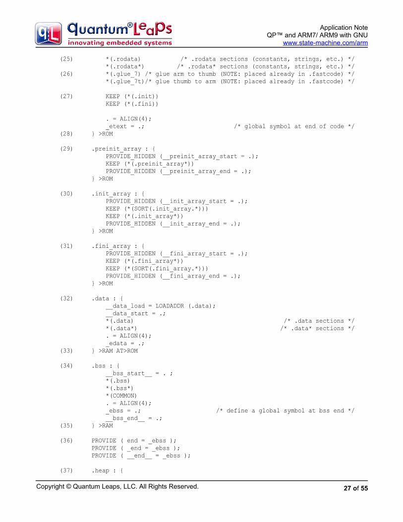
(25) *(.rodata) /* .rodata sections (constants, strings, etc.) */ *(.rodata*) /* .rodata* sections (constants, strings, etc.) */(26) *(.glue_7) /* glue arm to thumb (NOTE: placed already in .fastcode) */ *(.glue_7t)/* glue thumb to arm (NOTE: placed already in .fastcode) */
(27) KEEP (*(.init)) KEEP (*(.fini))
. = ALIGN(4); _etext = .; /* global symbol at end of code */(28) } >ROM
(29) .preinit_array : { PROVIDE_HIDDEN (__preinit_array_start = .); KEEP (*(.preinit_array*)) PROVIDE_HIDDEN (__preinit_array_end = .); } >ROM (30) .init_array : { PROVIDE_HIDDEN (__init_array_start = .); KEEP (*(SORT(.init_array.*))) KEEP (*(.init_array*)) PROVIDE_HIDDEN (__init_array_end = .); } >ROM (31) .fini_array : { PROVIDE_HIDDEN (__fini_array_start = .); KEEP (*(.fini_array*)) KEEP (*(SORT(.fini_array.*))) PROVIDE_HIDDEN (__fini_array_end = .); } >ROM
(32) .data : { __data_load = LOADADDR (.data); __data_start = .; *(.data) /* .data sections */ *(.data*) /* .data* sections */ . = ALIGN(4); _edata = .;(33) } >RAM AT>ROM
(34) .bss : { __bss_start__ = . ; *(.bss) *(.bss*) *(COMMON) . = ALIGN(4); _ebss = .; /* define a global symbol at bss end */ __bss_end__ = .;(35) } >RAM
(36) PROVIDE ( end = _ebss ); PROVIDE ( _end = _ebss ); PROVIDE ( __end__ = _ebss );
(37) .heap : {
27 of 55

Copyright © Quantum Leaps, LLC. All Rights Reserved.
Application NoteQP™ and ARM7/ ARM9 with GNU
www.state-machine.com/arm
__heap_start__ = . ; . = . + HEAP_SIZE; . = ALIGN(4); __heap_end__ = . ; } >RAM
(38) .stack : { __stack_start__ = . ; . += STACK_SIZE; . = ALIGN (4); __c_stack_top__ = . ; __stack_end__ = .; } >RAM
/* Remove information from the standard libraries */ /DISCARD/ : { libc.a ( * ) libm.a ( * ) libgcc.a ( * ) } }
Listing 5 shows the linker script for the DPP example application. The script is almost identical for C and C++ versions, with the minor differences discussed later in this section. The highlights of the linker script are as follows:
(1) The OUTPUT_FORMAT directive specifies the format of the output image (elf32, little-endian, ARM)
(2) OUTPUT_ARCH specifies the target machine architecture.
(3) ENTRY explicitly specifies the first instruction to execute in a program
(4) The MEMORY command describes the location and size of blocks of memory in the target.
(5) The region ROM corresponds to the on-chip flash of the AT91SAM7S64 device. It can contain read-only and executable sections (rx), it starts at 0x00100000 and is 64KB in size.
(6) The region RAM corresponds to the on-chip SRAM of the AT91SAM7S64 device. It can contain read-only, read-write and executable sections (rwx), it starts at 0x00200000 and is 16KB in size.
(7) The STACK_SIZE symbol determines the sizes of the ARM stack. You need to adjust the sizes for your particular application. The stack size cannot be zero.
NOTE: The QP port to ARM uses only one stack (the USER/SYSTEM stack).
(8) The HEAP_SIZE symbol determines the sizes of the heap. You need to adjust the sizes for your particular application. The heap size can be zero.
(9) The .reset section contains the startup code (including the ARM vectors) and must be located as the first section in ROM.
(10) This line locates all .text sections from the startup.o object module.
(11) The section size is aligned to the 4-byte boundary
(12) This section is loaded directly to the ROM region defined in the MEMORY command.
(13) The .ramvect section contains the RAM-based ARM vector table and the secondary jump table and must be loaded as the first section in RAM
28 of 55

Copyright © Quantum Leaps, LLC. All Rights Reserved.
Application NoteQP™ and ARM7/ ARM9 with GNU
www.state-machine.com/arm
(14) The ARM vector table and the secondary jump table have known size of 0x40 bytes. The current location counter is simply incremented to reserve 0x40 bytes for the section.
(15) The .ramvect section goes into the RAM region.
(16) The .fastcode section is used for RAM-based code, which needs to be loaded to ROM, but copied and executed from RAM.
(17) The .fastcode section has different load memory address (LMA) than the virtual memory address (VMA). The symbol __fastcode_load corresponds to the LMA in ROM and is needed by the startupcode to copy the section from ROM to RAM.
(18) The __fastcode_start symbol corresponds to the VMA of the .fastcode section and is needed bythe startup code to copy the section from ROM to RAM.
(19) The .glue_7t and .glue_7 sections are synthesized by the compiler when you specify the ARM-THUMB interworking option. The sections contain the “call veneers” between THUMB and ARM code and are accessed frequently by every call between ARM and THUMB. It’s typically advantageous to place this small amount of hot-spot code in RAM.
(20) The .text.fastcode section is assigned explicitly to individual functions in the C/C++ code by means of the __attribute__ ((section (".text.fastcode"))) command.
(21) The GNU compiler is also capable of placing each function in the separate section named after the function (requires specifying the option -ffunction-sections). This allows you to be very selectiveand to place individual functions (e.g. the function QF_run()) in RAM.
NOTE: The C++ compiler performs function name-mangling and you need to consult the map file to figure out the section name assigned to a given function. For example, the class method QF::run() is placed in the section .text._ZN2QF3runEv)
(22) You can place more hot-spot functions in RAM during the fine-tuning stage of the project.
(23) The .fastcode section is located in RAM, but is loaded at the ROM address.
(24) The .text section is for code and read-only data accessed in place.
(25) The section .rodata is used for read-only (constant) data, such as look-up tables. Just as code, youmight choose to place some frequently accessed constants in RAM by locating these sections in the.fastcode section.
(26) If you repeat sections already located in the .fastcode section, the earlier location will take precedence. However, if you decide to remove these sections from .fastcode, they will be located per the second specification.
(27) The .init and .fini sections are synthesized by the GNU C++ compiler and are used for static constructors and destructors. These sections are empty in C programs.
(28) The .text section is located and loaded to ROM.
(29,30) The .preinint_array and .inint_array sections hold arrays of function pointers that are called by the startup code to initialize the program. In C++ programs these hold pointers to the static constructors that are called by __libc_init_array() before main().
(31) The .fini_array section holds an array of function pointers that are called before terminating the program. In C++ programs this array holds pointers to the static destructors.
(32) The .data section contains initialized data.
(33) The .data section is located in RAM, but is loaded to ROM and copied to RAM during startup.
29 of 55

Copyright © Quantum Leaps, LLC. All Rights Reserved.
Application NoteQP™ and ARM7/ ARM9 with GNU
www.state-machine.com/arm
(34) The .bss section contains uninitialized data. The C/C++ standard requires that this section must be cleared at startup.
(35) The .bss section is located in RAM only.
(36) The symbols marking the end of the .bss sections are used by the startup code to allocate the beginning of the heap.
(37) The .heap section contains the heap (please also see the HEAP_SIZE symbol definition in line (8))
NOTE: Even though the linker script supports the heap, it is almost never a good idea to use the heap in embedded systems. Therefore the examples provided with this Application Note contain the file no_heap.c/cpp, which contains dummy definitions of malloc()/free()/realloc() functions. Linking this file saves some 2.8KB of code space compared to the actual implementation of the memory allocating functions.
(38) The .stack section contains the C stack (please also see the STACK_SIZE symbol definition in line (7)). The stack memory is initialized with a given bit-pattern at startup.
NOTE: The QP port to ARM uses only one stack (the USER/SYSTEM stack). Other ARM stacks, such as IRQ, FIQ, SUPERVISOR, or ABORT are not used and not even initialized.
4.1 Linker Options
The linker options for C and C++ are the same and are defined in the Makefile located in the DPP directory. The most
Linker options for C and C++ builds.
(1) LINKFLAGS = -T ./$(APP_NAME).ld \(2) -o $(BINDIR)/$(APP_NAME).elf \(3) -Wl,-Map,$(BINDIR)/$(APP_NAME).map,--cref,--gc-sections
(1) –T option specifies the name of the linker script (dpp.ld in this case).
(2) –o option specifies the name of image file (dpp.elf in this case).
(3) --gc-sections enable garbage collection of unused input sections..
NOTE: This bare-metal application replaces the standard startup sequence defined in crt0.o with the customized startup code. Even so, the linker option -nostartfiles is not used, because some parts of the standard startup codeare actually used. The startup code is specifically important for the C++ version, which requires calling the static constructors before calling main().
30 of 55

Copyright © Quantum Leaps, LLC. All Rights Reserved.
Application NoteQP™ and ARM7/ ARM9 with GNU
www.state-machine.com/arm
5 C/C++ Compiler Options and Minimizing the Overhead of C++The compiler options for C are defined in the Makefile located in the DPP directory. The Makefile specifies different options for building debug and release configurations and allows compiling to ARM or Thumb on the module-by-module basis.
5.1 Compiler Options for C
Listing 6: Compiler options used for C project, debug configuration (a)and release configuration (b).
ARM_CORE = arm7tdmi
CCFLAGS = -g -c \(1a) -mcpu=$(ARM_CORE) \(2a) -mthumb-interwork \(3a) -mlong-calls \(4a) -ffunction-sections \(5a) -O \
-Wall
CCFLAGS = -c \(1b) -mcpu=$(ARM_CORE) \(2b) -mthumb-interwork \(3b) -mlong-calls \(4b) -ffunction-sections \(5b) -Os \(6b) -DNDEBUG \
-Wall
Listing 6 shows the most important compiler options for C, which are:
(1) –mcpu option specifies the name of the target ARM processor. GCC uses this name to determine what kind of instructions it can emit when generating assembly code. Currently, the ARM_CORE symbol is set to arm7tdmi.
(2) –mthumb-interwork allows freely mixing ARM and Thumb code
(3) –mlong-calls tells the compiler to perform function calls by first loading the address of the function into a register and then performing a subroutine call on this register (BX instruction). This allows the called function to be located anywhere in the 32-bit address space, which is sometimes necessary for control transfer between ROM- and RAM-based code.
NOTE: The need for long calls really depends on the memory map of a given ARM-based MCU. For example, the Atmel AT91SAM7 family actually does not require long calls between ROM and RAM, because the memories are less than 25-bits apart. On the other hand, the NXP LPC2xxx family requires long calls because the ROM and RAM are mapped to addresses 0x0 and 0x40000000, respectively. The long-calls option is safe for any memory map.
(4) –ffunction-sections instructs the compiler to place each function into its own section in the outputfile. The name of the function determines the section's name in the output file. For example, the function QF_run() is placed in the section .text.QF_run. You can then choose to locate just this section in the most appropriate memory, such as RAM.
(5) –O chooses the optimization level. Release configuration has a higher optimization level (5b).
31 of 55

Copyright © Quantum Leaps, LLC. All Rights Reserved.
Application NoteQP™ and ARM7/ ARM9 with GNU
www.state-machine.com/arm
(6) the release configuration defines the macro NDEBUG.
5.2 Compiler Options for C++
The compiler options for C++ are defined in the Makefile located in the QP/C++ subdirectory. The Makefile specifies different options for building the Debug and Release configurations and allows compiling to ARM or Thumb on the module-by-module basis.
Listing 7 Compiler options used for C++ project.
CPPFLAGS = -g -gdwarf-2 -c -mcpu=$(ARM_CPU) -mthumb-interwork \-mlong-calls -ffunction-sections -O \
(1) -fno-rtti \ (2) -fno-exceptions \
-Wall
The C++ Makefile located in the directory DPP uses the same options as C discussed in the previous section plus two options that control the C++ dialect:
(1) –fno-rtti disables generation of information about every class with virtual functions for use by the C++ runtime type identification features (dynamic_cast and typeid). Disabling RTTI eliminates several KB of support code from the C++ runtime library (assuming that you don’t link with code that uses RTTI). Note that the dynamic_cast operator can still be used for casts that do not require runtime type information, i.e. casts to void * or to unambiguous base classes.
(2) –fno-exceptions stops generating extra code needed to propagate exceptions, which can produce significant data size overhead. Disabling exception handling eliminates several KB of support code from the C++ runtime library (assuming that you don’t link external code that uses exception handling).
5.3 Reducing the Overhead of C++
The compiler options controlling the C++ dialect are closely related to reducing the overhead of C++. However, disabling RTTI and exception handling at the compiler level is still not enough to prevent the GNU linker from pulling in some 50KB of library code. This is because the standard new and delete operators throw exceptions and therefore require the library support for exception handling. (The new anddelete operators are used in the static constructor/destructor invocation code, so are linked in even if you don’t use the heap anywhere in your application.)
Most low-end ARM-based MCUs cannot tolerate 50KB code overhead. To eliminate that code you need to define your own, non-throwing versions of global new and delete, which is done in the module mini_cpp.cpp located in the QP/C++ directory.
Listing 8: The mini_cpp.cpp module with non-throwing new and delete as well as dummy version of __cxa_atexit().
#include <stdlib.h> // for prototypes of malloc() and free() //............................................................................ (1) void *operator new(size_t size) throw() { return malloc(size); } //............................................................................ (2) void operator delete(void *p) throw() { free(p); } //............................................................................
32 of 55

Copyright © Quantum Leaps, LLC. All Rights Reserved.
Application NoteQP™ and ARM7/ ARM9 with GNU
www.state-machine.com/arm
(3) extern "C" void __cxa_atexit(void (*arg1)(void *), void *arg2, void *arg3) { }
shows the minimal C++ support that eliminates entirely the exception handling code. The highlights are as follows:
(1) The standard version of the operator new throws std::bad_alloc exception. This version explicitly throws no exceptions. This minimal implementation uses the standard malloc().
(2) This minimal implementation of the operator delete uses the standard free().
(3) The function __cxa_atexit() handles the static destructors. In a bare-metal system this function can be empty because application has no operating system to return to, and consequently the static destructors are never called.
Finally, if you don’t use the heap, which you shouldn’t in robust, deterministic applications, you can reduce the C++ overhead even further (by about 2.8KB). The module no_heap.cpp provides dummy empty definitions of malloc() and free():
#include <stdlib.h> // for prototypes of malloc() and free()
//............................................................................ extern "C" void *malloc(size_t) { return (void *)0; } //............................................................................ extern "C" void free(void *) { }
The most important GNU compiler options used are as follows:
-mthumb-interwork-mlong-calls -ffunction-sections-mcpu=$(ARM_CORE)
The option -mthumb-interwork specifies ARM/THUMB interworking code generation, which is code synthesized by the compiler and linker to perform CPU mode changes when calling ARM functions from THUMB, or THUMB functions from ARM. The option –mlong-calls specifies that the compiler should generate function calls with the BX instruction, which can use the whole 32-bit address space. This might be necessary for calling functions in RAM (in the .fastcode section). The option –ffunction-sections instructs the compiler to place every function in its own section, so that you can easily fine-tune the location of this section in the linker script.
The option -mcpu=$(ARM_CORE) option selects the ARM processor core, such as ARM7TDMI, ARM966E-S, and others.
The freedom of choosing the instruction set means that each individual module can be compiled either to ARM (-marm) or THUMB (-mthumb) for best performance and memory usage.
33 of 55

Copyright © Quantum Leaps, LLC. All Rights Reserved.
Application NoteQP™ and ARM7/ ARM9 with GNU
www.state-machine.com/arm
6 The Vanilla PortThe “vanilla” port shows how to use QP™ state machine frameworks on a “bare metal” ARM-based system with the cooperative “vanilla” kernel. In the “vanilla” version of the QP, the only component requiring platform-specific porting is the QF. The other two components: QEP and QS require merely recompilation and will not be discussed here. With the vanilla port you’re not using the QK component.
6.1 The QF Port Header File
The QF header file for the ARM port is located in <qp>\ports\arm\vanilla\gnu\qf_port.h. This file specifies the interrupt disabling policy (QF critical section) as well as the interrupt “wrapper” functions in assembly.
6.1.1 The QF Critical Section
This QF port uses the interrupt disabling policy of saving and restoring the interrupt status described as inSection 7.3.1 of the “Practical UML Statecharts in C/C++, Second Edition” [PSiCC2]. This policy allows fornesting critical sections, where the interrupts status is preserved across the critical section in a temporary stack variable. In other words, upon the exit from a critical section the interrupts are actually enabled in the QF_INT_ENABLE() macro only if they were enabled before the matching QF_INT_DISABLE() macro. Conversely, interrupts will remain disabled after the QF_INT_ENABLE() macro if they were disabled beforethe matching QF_INT_DISABLE() macro.
As discussed in the upcoming Section “The FIQ Wrapper Function in Assembly”, you’ll typically not enable the ARM core interrupts during the FIQ interrupt processing, so the described critical section nesting will occur.
The critical section in QF is defined as follows:
Listing 9: QF critical section definition
/* fast unconditional interrupt disabling/enabling for ARM state, NOTE01 */ (1) #define QF_INT_DISABLE() \ __asm volatile ("MSR cpsr_c,#(0x1F | 0x80)" ::: "cc")
(2) #define QF_INT_ENABLE() \ __asm volatile ("MSR cpsr_c,#(0x1F)" ::: "cc")
/* QF critical section entry/exit */ (3) #ifdef __thumb__ /* THUMB mode? */ /* QF interrupt disabling/enabling */ (4) #define QF_CRIT_STAT_TYPE unsigned int (5) #define QF_CRIT_ENTRY(stat_) ((stat_) = QF_int_disable_SYS()) (6) #define QF_CRIT_EXIT(stat_) QF_int_enable_SYS(stat_)
(7) QF_CRIT_STAT_TYPE QF_int_disable_SYS(void); (8) void QF_int_enable_SYS(QF_CRIT_STAT_TYPE stat);
(9) #elif (defined __arm__) /* ARM mode? */
(10) #define QF_CRIT_STAT_TYPE unsigned int(11) #define QF_CRIT_ENTRY(stat_) do { \(12) __asm volatile ("MRS %0,cpsr" : "=r" (stat_) :: "cc"); \
34 of 55
Copyright © Quantum Leaps, LLC. All Rights Reserved.
Application NoteQP™ and ARM7/ ARM9 with GNU
www.state-machine.com/arm
(13) QF_INT_DISABLE(); \ } while (0)(14) #define QF_CRIT_EXIT(stat_) \(15) __asm volatile ("MSR cpsr_c,%0" :: "r" (stat_) : "cc")
#else
#error Incorrect CPU mode. Must be either __arm__ or __thumb__.
#endif
void QF_reset(void); void QF_undef(void); void QF_swi(void); void QF_pAbort(void); void QF_dAbort(void); void QF_reserved(void);(16) void QF_fiq_dummy(void);
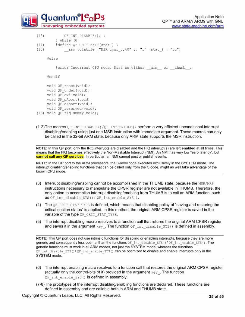
(1-2)The macros QF_INT_DISABLE()/QF_INT_ENABLE() perform a very efficient unconditional interrupt disabling/enabling using just one MSR instruction with immediate argument. These macros can only be called in the 32-bit ARM state, because only ARM state supports the MSR instruction.
NOTE: In this QP port, only the IRQ interrupts are disabled and the FIQ interrupt(s) are left enabled at all times. This means that the FIQ becomes effectively the Non-Maskable Interrupt (NMI). An NMI has very low “zero latency”, but cannot call any QF services. In particular, an NMI cannot post or publish events.
NOTE: In the QP port to the ARM processors, the C-level code executes exclusively in the SYSTEM mode. The interrupt disabling/enabling functions that can be called only from the C code, might as well take advantage of the known CPU mode.
(3) Interrupt disabling/enabling cannot be accomplished in the THUMB state, because the MSR/MRS instructions necessary to manipulate the CPSR register are not available in THUMB. Therefore, the only option to accomplish interrupt disabling/enabling from THUMB is to call an ARM function, such as QF_int_disable_SYS()/ QF_int_enable_SYS().
(4) The QF_CRIT_STAT_TYPE is defined, which means that disabling policy of “saving and restoring the critical section status” is applied. In this method, the original ARM CPSR register is saved in the variable of the type QF_CRIT_STAT_TYPE.
(5) The interrupt disabling macro resolves to a function call that returns the original ARM CPSR register and saves it in the argument key_. The function QF_int_disable_SYS() is defined in assembly.
NOTE: This QP port does not use intrinsic functions for disabling or enabling interrupts, because they are more generic and consequently less optimal than the functions QF_int_disable_SYS()/ QF_int_enable_SYS(). The generic functions must work in all ARM modes, not just the SYSTEM mode, whereas the functions QF_int_disable_SYS()/ QF_int_enable_SYS() can be optimized to disable and enable interrupts only in the SYSTEM mode.
(6) The interrupt enabling macro resolves to a function call that restores the original ARM CPSR register(actually only the control-bits of it) provided in the argument key_. The function QF_int_enable_SYS() is defined in assembly.
(7-8)The prototypes of the interrupt disabling/enabling functions are declared. These functions are defined in assembly and are callable both in ARM and THUMB state.
35 of 55

Copyright © Quantum Leaps, LLC. All Rights Reserved.
Application NoteQP™ and ARM7/ ARM9 with GNU
www.state-machine.com/arm
NOTE: In C++ the interrupt disabling/enabling functions must be declared extern “C” to avoid C++ name decorating, which would make it difficult to define these functions in assembly.
(9) The interrupt disabling macro is defined inline in the ARM state.
(10) The interrupt key holds the CPSR value (actually only the control-bits of it), which is obtained by means of the intrinsic function __get_CPSR(). In the ARM state, this function expands to a single machine instruction MRS r?,CPSR_c.
(11-13) After saving the CPSR, the interrupts are efficiently disabled with macro QF_INT_DISABLE() described in step (2) above.
(14-15) The interrupt enabling macro for the ISR-level restores the CPSR from the saved interrupt key value. The intrinsic function __set_CPSR() expands to a single machine instruction MSR CPSR_c,r?.
(16) The QF_fiq_dummy() function should never be called, because it causes an assertion violation.
The interrupt disabling and enabling functions are defined in the assembly file <qp>\qf\arm\vanilla\-gnu\qf_port.s as follows:
Listing 10: Interrupt disabling and enabling functions defined in the module qf_port.s.
/* use the special section (.text.fastcode), to enable fine-tuning * of the placement of this section inside the linker script */ (1) .section .text.fastcode (2) .arm
/***************************************************************************** * QF_CRIT_STAT_TYPE QF_int_disable_SYS(void); */
.global QF_int_disable_SYS .func QF_int_disable_SYS QF_int_disable_SYS: (3) MRS r0,cpsr ; get the original CPSR in r0 to return (4) MSR cpsr_c,#(SYS_MODE | NO_INT) ; disable both IRQ/FIQ in SYSTEM mode (5) BX lr ; return the original CPSR in r0
/***************************************************************************** * void QF_int_enable_SYS(QF_CRIT_STAT_TYPE key); */ .global QF_int_enable_SYS .func QF_int_enable_SYS QF_int_enable_SYS: (6) MSR cpsr_c,r0 ; restore the original CPSR from r0 (7) BX lr ; return to ARM or THUMB
(1) The module is declared in the section .fastcode located in RAM. For almost all ARM-based MCUs, the code executing from RAM is significantly faster (sometimes as much as 3-4 times faster) than code executing from ROM due to wait states necessary to access slow, and often only 16-bit wide Flash ROM. At the cost of just several bytes of RAM you get significant performance boost for the “hot-spot” interrupt disabling/enabling code.
(2) The functions are entered in 32-bit ARM state.
36 of 55

Copyright © Quantum Leaps, LLC. All Rights Reserved.
Application NoteQP™ and ARM7/ ARM9 with GNU
www.state-machine.com/arm
(3) The original value of CPSR is moved to r0, which is then returned from the QF_int_disable function.
(4) The IRQ and FIQ are disabled simultaneously by means of the most efficient immediate move to the CPSR_c (control bits only). Using this efficient instruction is possible, because the mode bits are known to be SYSTEM. Also, the T-bit is known to be cleared since this code executes in the ARM state.
NOTE: In this ARM port, the C-level code executes exclusively in the SYSTEM mode. The interrupt disabling/enabling functions that can be called only from the C code, might as well take advantage of the known CPU mode. Because these specific interrupt disabling/enabling functions assume the SYSTEM mode, the names of thesefunctions have been chosen to reflect this fact (QF_int_disable_SYS(), QF_int_enable_SYS()).
(5) The return from the function occurs via the BX instruction, which causes the T-bit to be set in the CPSR_c if the return address is a THUMB label.
(6) The original value of CPSR, which is passed in the argument of the QF_int_enable_SYS function is moved to CPSR_c. At this point interrupts are re-enabled if they were enabled before the matching call to QF_int_disable_SYS, or they remain disabled, if they were disabled before the call.
(7) The function .QF_int_enable_SYS returns with the BX instruction, so the T-bit is set in the CPSR_c if the return address is a THUMB label.
6.1.2 Discussion of the QF Critical Section
When the IRQ line of the ARM processor is asserted, and the I bit (bit CPSR[7]) is cleared, the core ends the instruction currently in progress and then starts the IRQ sequence, which performs the following actions (“ARM Architecture Reference Manual, 2nd Edition”, Section 2.6.6 [Seal 00]):
• R14_irq = address of next instruction to be executed + 4
• SPSR_irq = CPSR
• CPSR[4:0] = 0b10010 (enter IRQ mode)
• CPSR[7] = 1, NOTE: CPSR[6] is unchanged
• PC = 0x00000018
The ARM Technical Note “What happens if an interrupt occurs as it is being disabled?” [ARM 05], points out two potential problems. Problem 1 is related to using a particular subroutine as an IRQ handler and asa regular subroutine called outside of the IRQ scope and then inspecting the SPSR_IRQ register to detect in which context the handler function is called. This is impossible in this QF port, because the C-level IRQ handler is always called in the SYSTEM mode, where the application programmer has no access to the SPSR_IRQ register. Problem 2 described in the ARM Note [ARM 05] is more applicable and relates to the situation when both IRQ and FIQ are disabled simultaneously, which is actually the case in this port (seeListing 10(4)). If the IRQ is received during the CPSR write, FIQs could be disabled for the execution time of the IRQ handler. One of the workarounds recommended in the ARM Note is to explicitly enable FIQ very early in the IRQ handler. This is exactly done in the QF_irq assembler “wrapper” discussed later in this document.
For completeness, this discussion should mention the Atmel Application Note “Disabling Interrupts at Processor Level” [Atmel 98a], which describes another potential problem that might occur when the IRQ or FIQ interrupt is recognized exactly at the time that it is being disabled. While the ARM core is executingthe “MSR cpsr_c,#(SYS_MODE | NO_INT)” instruction (see Listing 10(4)), the interrupts are disabled only on the next clock cycle. If, for example, an IRQ interrupt occurs exactly during the execution of this instruction, the CPSR[7] bit is set both in the CPSR and SPSR_irq (Saved Program Status Register) and
37 of 55

Copyright © Quantum Leaps, LLC. All Rights Reserved.
Application NoteQP™ and ARM7/ ARM9 with GNU
www.state-machine.com/arm
the IRQ is entered. The problem arises when the IRQ or FIQ handler would manipulate the I or F bits in the SPSR register. This QF port provides the IRQ and FIQ “wrappers” in assembly that never change any bits in the SPSR. This approach corresponds to the Workaround 1 described in the Atmel Application Note [Atmel 98a], which is safe here because the application programmer really has no way of accessing the SPSR register.
NOTE: In this ARM port, the C-level code executes exclusively in the SYSTEM mode. Therefore, the banked registers SPSR_irq or SPSR_fiq aren’t really visible or accessible to the application programmer. Also accessing these registers would necessarily require assembly programming, since no standard compiler functions use these registers.
6.2 Handling Interrupts
This generic “vanilla” port to ARM can work with or without an interrupt controller, such as the Atmel’s Advanced Interrupt Controller (AIC), Philips’ Vectored Interrupt Controller (VIC), and others.
When used with an interrupt controller, the “vanilla” port assumes no “auto-vectoring”, which is described for example in the Atmel Application Note “Interrupt Management: Auto-vectoring and Prioritization” [Atmel 98b].
Side Note: Auto-vectoring occurs when the following LDR instruction is located at the address 0x18 for the IRQ (this example pertains to the Atmel’s AIC):
ORG 0x18 LDR pc,[pc,#-0xF20]
When an IRQ occurs, the ARM core forces the PC to address 0x18 and executes the LDR pc,[pc,#-0xF20] instruction. When the instruction at address 0x18 is executed, the effective address is:
0x20 – 0xF20 = 0xFFFFF100
(0x20 is the value of the PC when the instruction at address 0x18 is executed due to pipelining of the ARM core).
This causes the ARM core to load the PC with the value read from the AIC_IVR register located at 0xFFFFF100. The read cycle causes the AIC_IVR register to return the address of the currently active interrupt service routine. Thus, the single LDR pc,[pc,#-0xF20] instruction has the effect of directly jumping to the correct ISR, which is called auto-vectoring.
Instead of “auto-vectoring”, both the “vanilla” and QK ports to ARM assume that the low-level interrupt handlers are directly invoked upon hardware interrupt requests. The IRQ/FIQ vectors (at 0x18 and 0x1C, respectively) load the PC with the address of the “wrapper” routines written in assembly.
Figure 10: Typical ARM system with an interrupt controller (external to the ARM core)
38 of 55

Copyright © Quantum Leaps, LLC. All Rights Reserved.
Application NoteQP™ and ARM7/ ARM9 with GNU
www.state-machine.com/arm
Figure 10 shows a typical ARM-based system with an interrupt controller. Typically, the interrupt prioritization is performed only with respect to the IRQ line, while the FIQ line is routed directly to the ARMcore. The ARM core itself performs a 2-level interrupt prioritization between the FIQ and IRQ, whereas FIQ is higher priority than the IRQ. This second-level of prioritization is performed by the I and F bits of the CPSR register, which are also used for interrupt disabling and enabling policy.
Figure 11: Interrupt processing in the “vanilla” port to ARM with the Atmel’s AIC interruptcontroller
Even though “auto vectoring” is not used, vectoring to a specific interrupt handler can still occur, but is done later, at the C-level interrupt handler functions implemented typically in the Board Support Package. Examples of such BSP functions for the popular interrupt controllers are provided later in this Application Note.
Figure 11 shows the interrupt processing sequence in the presence of an interrupt controller (Atmel’s AIC is assumed in this example). The ARM vector addresses 0x18 and 0x1C point to the assembler “wrapper”functions QF_irq and QF_fiq, respectively. Each of these “wrapper” functions, for example QF_irq, performs context save, switches to the SYSTEM mode, and invokes a C-level function BSP_irq (or BSP_fiq for the FIQ interrupt). BSP_irq encapsulates the particular interrupt controller, from which it explicitly obtains the interrupt vector. Because the interrupt controller is used in this case, it must be initialized with the addresses of all used interrupt service routines (ISRs), such as tickIRQ() shown inFigure 11. Please note that these ISRs are regular C-functions and not __irq type functions because the interrupt entry and exit code is already provided in the assembly “wrapper” functions QF_irq and QF_fiq.
39 of 55

Copyright © Quantum Leaps, LLC. All Rights Reserved.
Application NoteQP™ and ARM7/ ARM9 with GNU
www.state-machine.com/arm
6.2.1 The IRQ “Wrapper” Function in Assembly
The “vanilla” QF port provides interrupt “wrapper” function QF_irq() for handling the IRQ-type interrupts. The function is coded entirely in assembly, and is located in the file <qp>\ports\arm\vainlla\gnu\src\qf_port.s.
Listing 11 The QF_irq assembly wrapper for the “vanilla” QF port defined in qf_port.s.
(1) .section .text.fastcode (2) .arm
.global QF_irq .func QF_irq .align 3 QF_irq: /* IRQ entry {{{ */ (3) MOV r13,r0 /* save r0 in r13_IRQ */ (4) SUB r0,lr,#4 /* put return address in r0_SYS */ (5) MOV lr,r1 /* save r1 in r14_IRQ (lr) */ (6) MRS r1,spsr /* put the SPSR in r1_SYS */
(7) MSR cpsr_c,#(SYS_MODE | NO_IRQ) /* SYSTEM, no IRQ, but FIQ enabled! */ (8) STMFD sp!,{r0,r1} /* save SPSR and PC on SYS stack */ (9) STMFD sp!,{r2-r3,r12,lr} /* save APCS-clobbered regs on SYS stack */(10) MOV r0,sp /* make the sp_SYS visible to IRQ mode */(11) SUB sp,sp,#(2*4) /* make room for stacking (r0_SYS, r1_SYS) */
(12) MSR cpsr_c,#(IRQ_MODE | NO_IRQ) /* IRQ mode, IRQ disabled */(13) STMFD r0!,{r13,r14} /* finish saving the context (r0_SYS,r1_SYS) */
(14) MSR cpsr_c,#(SYS_MODE | NO_IRQ) /* SYSTEM mode, IRQ disabled */ /* IRQ entry }}} */
/* NOTE: BSP_irq might re-enable IRQ interrupts (the FIQ is enabled * already), if IRQs are prioritized by the interrupt controller. */(15) LDR r12,=BSP_irq(16) MOV lr,pc /* copy the return address to link register */(17) BX r12 /* call the C IRQ-handler (ARM/THUMB) */
/* IRQ exit {{{(18) MSR cpsr_c,#(SYS_MODE | NO_IRQ) /* make sure IRQ are disabled */(19) MOV r0,sp /* make sp_SYS visible to IRQ mode */(20) ADD sp,sp,#(8*4) /* fake unstacking 8 registers from sp_SYS */
(21) MSR cpsr_c,#(IRQ_MODE | NO_IRQ) /* IRQ mode, IRQ disabled */(22) MOV sp,r0 /* copy sp_SYS to sp_IRQ */(23) LDR r0,[sp,#(7*4)] /* load the saved SPSR from the stack */(24) MSR spsr_cxsf,r0 /* copy it into spsr_IRQ */
(25) LDMFD sp,{r0-r3,r12,lr}^ /* unstack all saved USER/SYSTEM registers */(26) NOP /* can't access banked reg immediately */(27) LDR lr,[sp,#(6*4)] /* load return address from the SYS stack */(28) MOVS pc,lr /* return restoring CPSR from SPSR */ /* IRQ exit }}}
40 of 55

Copyright © Quantum Leaps, LLC. All Rights Reserved.
Application NoteQP™ and ARM7/ ARM9 with GNU
www.state-machine.com/arm
(1) The IRQ wrapper QF_irq is defined in section .fastcode placed in RAM for fastest execution. Such time-critical ARM code is best executed from 32-bit wide memory with minimal number of wait states.
(2) The IRQ handler must be written in the 32-bit instruction set (ARM), because the ARM core automatically switches to the ARM state when IRQ is recognized.
(3) The IRQ stack is not used, so the banked stack pointer register r13_IRQ (sp_IRQ) is used as a scratchpad register to temporarily hold r0 from the SYSTEM context.
NOTE: As part of the IRQ startup sequence, the ARM processor sets the I bit in the CPSR (CPSR[7] = 1), but leaves the F bit unchanged (typically cleared), meaning that further IRQs are disabled, but FIQs are not. This means that FIQ can be recognized while the ARM core is in the IRQ mode. This IRQ handler does not disable the FIQ and preemption, and the provided FIQ handler can safely preempt this IRQ until FIQs are explicitly disabled later in the sequence.
(4) Now r0 can be clobbered with the return address from the interrupt that needs to be saved to the SYSTEM stack.
(5) At this point the banked lr_IRQ register can be reused to temporarily hold r1 from the SYSTEM context.
(6) Now r1 can be clobbered with the value of SPSR_IRQ register (Saved Program Status Register) that needs to be saved to the SYSTEM stack.
(7) Mode is changed to SYSTEM with IRQ interrupt disabled, but FIQ explicitly enabled. This mode switch is performed to get access to the SYSTEM registers.
NOTE: The F bit in the CPSR is intentionally cleared at this step (meaning that the FIQ is explicitly enabled). Among others, this represents the workaround for the Problem 2 described in ARM Technical Note “What happens if an interrupt occurs as it is being disabled?” [ARM 05].
(8) The SPSR register and the return address from the interrupt (PC after the interrupt) are pushed on the SYSTEM stack.
(9) All registers (except r0 and r1) clobbered by the AAPCS (ARM Architecture Procedure Call Standard) [ARM 06] are pushed on the SYSTEM stack.
(10) The SYSTEM stack pointer is placed in r0 to be visible in the IRQ mode.
(11) The SYSTEM stack pointer is adjusted to make room for two more registers of the saved IRQ context. By adjusting the SYSTEM stack pointer, the IRQ handler can still keep FIQ enabled without the concern of corrupting the SYSTEM stack space reserved for the IRQ context.
(12) The mode is switched back to IRQ with IRQ interrupt disabled, but FIQ still enabled. This is done to get access to the rest of the context sitting in the IRQ-banked registers.
(13) The context is entirely saved by pushing the original r0 and r1 (still sitting in the banked IRQ Registers r14_IRQ and r13_IRQ, respectively) to the SYSTEM stack. At this point the saved SYSTEM stack frame contains 8 registers and looks as follows (this is exactly the ARM v7-M interrupt stack frame [ARM 06]):
high memory SPSR PC (return address) LR
41 of 55

Copyright © Quantum Leaps, LLC. All Rights Reserved.
Application NoteQP™ and ARM7/ ARM9 with GNU
www.state-machine.com/arm
| R12 v R3 stack R2 growth R1 R0 <-- sp_SYSlow memory
(14) The mode is switched once more to SYSTEM with IRQ disabled and FIQ enabled. Please note that the stack pointer sp_SYS points to the top of the stack frame, because it has been adjusted after the first switch to the SYSTEM mode at line (11).
(15-17) The board-specific function BSP_irq() is called to perform the interrupt processing at the application-level. Please note that BSP_irq() is now a regular C function in ARM or Thumb. Typically, this function uses the silicon-vendor specific interrupt controller (such as the Atmel AIC) to vector into the current interrupt.
NOTE: The BSP_irq() function is entered with IRQ disabled (and FIQ enabled), but it can internally enable IRQs, if the MCU is equipped with an interrupt controller that performs prioritization of IRQs in hardware.
(18) IRQ interrupts are disabled to execute the following instructions atomically.
(19) The sp_SYS register is moved to r0 to make it visible in the IRQ mode.
(20) Before leaving the SYSTEM mode, the sp_SYS stack pointer is adjusted to un-stack the whole interrupt stack frame of 8 registers. This brings the SYSTEM stack to exactly the same state as be-fore the interrupt occurred.
NOTE: Even though the SYSTEM stack pointer is moved up, the stack contents have not been restored yet. At this point it’s critical that the interrupts are disabled, so that the stack contents above the adjusted stack pointer cannot becorrupted.
(21) The mode is changed to IRQ with IRQ interrupts disabled to perform the final return from the IRQ.
(22) The SYSTEM stack pointer is copied to the banked sp_IRQ, which thus is set to point to the top of the SYSTEM stack
(23-24) The value of SPSR is loaded from the stack (please note that the SPSR is now 7 registers away from the top of the stack) and placed in SPSR_irq.
(25) The 6 registers are popped from the SYSTEM stack. Please note the special version of the LDM instruction (with the ‘^’ at the end), which means that the registers are popped from the SYSTEM/USER stack. Please also note that the special LDM(2) instruction does not allow the write-back, so the stack pointer is not adjusted. (For more information please refer to Section “LDM(2)” in the “ARM Architecture Reference Manual” [Seal 00].)
(26) It’s important not to access any banked register after the special LDM(2) instruction.
(27) The return address is retrieved from the stack. Please note that the return address is now 6 registersaway from the top of the stack.
(28) The interrupt return involves loading the PC with the return address and the CPSR with the SPSR, which is accomplished by the special version of the MOVS pc,lr instruction.
42 of 55

Copyright © Quantum Leaps, LLC. All Rights Reserved.
Application NoteQP™ and ARM7/ ARM9 with GNU
www.state-machine.com/arm
6.2.2 The FIQ Dummy Implementation
Generally, the FIQ interrupt is NOT prioritized by the interrupt controller in most ARM chips (see Figure 10). This QP port never disables the FIQ, which becomes a Non-Maskable-Interrupt (NMI) for handling very special functions.
NOTE: This QP port to the GNU compiler configures the FIQ as a NMI. Handling the FIQ as general purpose interrupt is actually more complicated (and thus actually more expensive) than handling of IRQ-type interrupts that typically are prioritized in the interrupt controller. Please refer the QP-ARM port with the IAR compiler [QP-ARM-IAR] for the alternative configuration, in which the FIQ is handled as a general-purpose interrupt.
The “vanilla” QF port provides a dummy implementation QF_fiq_dummy() (see Listing 12), which should never be called. Instead, the FIQ must be specified at the application level and must be typically defined in assembly.
Listing 12: The QF_fiq_dummy defined in qf_port.s.
.global QF_fiq_dummy .func QF_fiq_dummy .align 3 QF_fiq_dummy: LDR r0,=Csting_fiq B QF_except .size QF_fiq_dummy, . - QF_fiq_dummy .endfunc
6.2.3 Other ARM Exception “Wrapper” Functions in Assembly
The “vanilla” QF port provides also assembly “wrapper” functions for all other ARM exceptions, which are:RESET, UNDEFINED INSTRUCTION, SOFTWARE INTERRUPT, PREFETCH ABORT, DATA ABORT, and the RESERVED exception. All these exception handlers are coded entirely in assembly, and are located in the file <qp>\ports\arm\vainlla\gnu\src\qf_port.s.
The policy of handling the ARM hardware exceptions in QF is to raise an assertion, an assumption here being that no ARM exception should occur during normal program execution. You can easily substitute this standard behavior for selected ARM exceptions by simply initializing the ARM vector table to your own implementations.
Listing 13: ARM Exception “Wrapper” Functions in Assembly defined in qf_port.s.
/***************************************************************************** * void QF_reset(void); */ .global QF_reset .func QF_reset .align 3 QF_reset: LDR r0,Csting_reset B QF_except
/***************************************************************************** * void QF_undef(void); */ .global QF_undef .func QF_undef
43 of 55

Copyright © Quantum Leaps, LLC. All Rights Reserved.
Application NoteQP™ and ARM7/ ARM9 with GNU
www.state-machine.com/arm
.align 3 QF_undef: LDR r0,Csting_undef B QF_except
/***************************************************************************** * void QF_swi(void); */ .global QF_swi .func QF_swi .align 3 QF_swi: LDR r0,Csting_swi B QF_except
/***************************************************************************** * void QF_abort(void); */ .global QF_abort .func QF_abort .align 3 (1) QF_pAbort: (2) LDR r0,Csting_pAbort (3) B QF_except
/***************************************************************************** * void QF_dAbort(void); */ .global QF_dAbort .func QF_dAbort .align 3 QF_dAbort: LDR r0,Csting_dAbort B QF_except
/***************************************************************************** * void QF_reserved(void); */ .global QF_reserved .func QF_reserved .align 3 QF_reserved: LDR r0,Csting_reserved B QF_except
/***************************************************************************** * void QF_except(void); */ .global QF_except .func QF_except .align 3 (4) QF_except: (5) SUB r1,lr,#4 /* set line number to the exception address (6) MSR cpsr_c,#(SYS_MODE | NO_INT) /* SYSTEM mode, IRQ/FIQ disabled (7) LDR r12,=Q_onAssert (8) MOV lr,pc /* store the return address
44 of 55

Copyright © Quantum Leaps, LLC. All Rights Reserved.
Application NoteQP™ and ARM7/ ARM9 with GNU
www.state-machine.com/arm
(9) BX r12 /* call the assertion-handler (ARM/THUMB) /* the assertion handler should not return, but in case it does /* hang up the machine in this endless loop B .
Csting_reset: .string "Reset" Csting_undef: .string "Undefined" Csting_swi: .string "Software Int" Csting_pAbort: .string "Prefetch Abort" Csting_dAbort: .string "Data Abort" Csting_reserved: .string "Reserved"
.size QF_except, . - QF_except .endfunc
(1) All exceptions are handled uniformly, such as the PREFETCH ABORT exception.
(2) The first argument to the Q_onAssert() callback function is prepared in r0. This argument is a pointer to the C-string with the name of the exception.
(3-4)The common exception code is handled in at the QF_except label.
(5) The address of the exception is saved in r1, which is the second argument to the Q_onAssert() callback function .
(6) The mode is switched to SYSTEM with both IRQ and FIQ interrupts disabled.
(7-9)The Q_onAssert() callback function is called. Because the call happens via the BX instruction, the Q_onAssert() function can be in ARM or THUMB.
6.2.4 The Interrupt Controller-Specific Handler Function BSP_irq
As described above, the low-level interrupt “wrapper” function QF_irq() calls the C-function BSP_irq(), which encapsulates the particular interrupt controller of your ARM-based MCU. The BSP_irq() indirection layer is only necessary to separate the generic QF_irq() implementation from the vendor-specific interrupt controller interface.
If only the industry could agree on the standardized interface to the interrupt controller, the low-level IRQ handler QF_irq could perform the vectoring in a standard way and thus eliminate the need for the BSP_irq() indirection. However, the various ARM-silicon vendors use different register locations for their interrupt controllers, so it’s impossible to perform vectoring generically. (Of course, at the cost of losing generality you can eliminate the BSP_irq() function overhead by in-lining it directly inside QF_irq()).
NOTE: ARM Limited has standardized the interrupt controller interface in the new ARM v7-M architecture, which comes with the standard Nested Interrupt Controller (NVIC).
Listing 14 The BSP_irq() function defined in the file isr.c.
(1) __attribute__ ((section (".text.fastcode"))) (2) void BSP_irq(void) { (3) typedef void (*IntVector)(void); (4) IntVector vect = (IntVector)AT91C_BASE_AIC->AIC_IVR; /* read the IVR */ /* write IVR if AIC in protected mode */ (5) AT91C_BASE_AIC->AIC_IVR = (AT91_REG)vect;
(6) QF_INT_ENABLE(); /* allow nesting interrupts */
45 of 55

Copyright © Quantum Leaps, LLC. All Rights Reserved.
Application NoteQP™ and ARM7/ ARM9 with GNU
www.state-machine.com/arm
(7) (*vect)(); /* call the IRQ handler via the pointer to function */ (8) QF_INT_DISABLE(); /* disable IRQ before return */
/* write AIC_EOICR to clear interrupt */ (9) AT91C_BASE_AIC->AIC_EOICR = (AT91_REG)vect; }
Listing 14 shows the implementation of the BSP_irq() function for the Atmel’s AIC. The highlights of the code are as follows:
(1) The function BSP_irq() is assigned to the section .text.fastcode, which the linker script locates inRAM for faster execution.
(2) The BSP_irq() function is a regular C-function (not an IRQ-function!). It is entered with IRQ disabledand FIQ enabled.
(3) This typedef defines the pointer-to-function type for storing the address of the ISR obtained from the interrupt controller.
(4) The current interrupt vector is loaded from the AIC_IVR register into a temporary variable vect. Please note that BSP_irq() takes full advantage of the vectoring capability of the AIC, even though this is not the traditional auto-vectoring. For vectoring to work, the appropriate Source Vector Registers in the AIC must be initialized with the addresses of the corresponding interrupt service routines (ISRs).
(5) The AIC_IVR is written, which is necessary if the AIC is configured in protected mode (see Atmel’s documentation). The write cycle to the AIC_IVR starts prioritization of this IRQ.
(6) After the interrupt controller starts prioritizing this IRQ, it’s safe to enable interrupts at the ARM core level.
NOTE: Here the inline assembly is used to clear the I-bit in the CPSR register. The MSR instruction is available only in the ARM instruction set, which means that the module containing BSP_irq() must be compiled to ARM.
(7) The interrupt handler is invoked via the pointer-to-function (vector address) extracted previously fromthe AIC_IVR.
(8) After the ISR returns, IRQ interrupts are disabled at the ARM core level by means of inline assembly.
(9) The End-Of-Interrupt command is written to the AIC, which informs the interrupt controller to end prioritization of this IRQ.
6.2.5 Interrupt Service Routines (IRQ)
The main job of the BSP_irq() indirection layer is to obtain the address of the interrupt service routine (ISR) from the interrupt controller and to invoke the ISR. The ISRs are regular C-functions (not IRQ-type functions!). You are free to compile the ISRs to ARM or Thumb, as you see fit. Listing 15 shows examplesof ISRs for the DPP example application accompanying this Application Note.
Listing 15: Examples of ISRs.
(1) __attribute__ ((section (".text.fastcode"))) (2) static void tickIRQ(void) { (3) uint32_t tmp = AT91C_BASE_PITC->PITC_PIVR; /* clear interrupt source */ (4) QF_tick(); } /*..........................................................................*/
46 of 55

Copyright © Quantum Leaps, LLC. All Rights Reserved.
Application NoteQP™ and ARM7/ ARM9 with GNU
www.state-machine.com/arm
(5) void ISR_spur(void) { /* spurious ISR */ }
The highlights of Listing 15 are as follows:
(1) The function BSP_fiq() is assigned to the section .text.fastcode, which the linker script locates inRAM for faster execution.
(2) The C-level ISR is a regular void (void) C-function. The IRQ-type ISR is called in SYSTEM mode with interrupts unlocked at the ARM-core level.
NOTE: Here, the ISR is defined as an ARM function (via the __arm extended keyword) to avoid state switch from ARM to THUMB, because BSP_irq() is also defined as an ARM function. However, using ARM mode is here just a fine-tuning option and is not necessary for correctness. You could use THUMB mode (default) as well.
(3) Any level-sensitive interrupt sources must be cleared, such as the AT91 timer. Please note that eventhough the interrupts are unlocked at the ARM core level, they are still prioritized in the interrupt controller, so a level-sensitive interrupt source will not cause recursive ISR reentry.
(4) The work of the interrupt is performed with interrupts enabled at the ARM core level. Please note that the interrupt controller prevents the same level of interrupt from preempting the currently serviced level, so QF_tick() will never be reentered.
(5) The spurious ISR is empty.
NOTE: Spurious interrupts are possible in ARM7/ARM9-based MCUs due to asynchronous interrupt processing with respect to the system clock. A spurious interrupt is defined as being the assertion of an interrupt source long enough for the interrupt controller to assert the IRQ, but no longer present when interrupt vector register is read. The Atmel datasheet [9-1] and NXP Application Note [9-3] provide more information about spurious interrupts in ARM-based MCUs.
6.3 Idle Loop Customization in the “Vanilla” Port
As described in Chapter 7 of [PSiCC2], the “vanilla” port uses the non-preemptive scheduler built into QF.If no events are available, the non-preemptive scheduler invokes the platform-specific callback function QF_onIdle(), which you can use to save CPU power, or perform any other “idle” processing (such as Quantum Spy software trace output).
NOTE: The idle callback QF_onIdle() must be invoked with interrupts disabled, because the idle condition can be changed by any interrupt that posts events to event queues. QF_onIdle() must internally enable interrupts, ideally atomically with putting the CPU to the power-saving mode.
Because QF_onIdle() must enable interrupts internally, the signature of the function depends on the interrupt locking policy. In case of the “save and restore interrupt status” policy, which is used in this ARM port, the QF_onIdle() takes the interrupt status as a parameter, to be able to use the QF_INT_ENABLE() macro to enable the interrupts.
The following Listing 16 shows an example implementation of QF_onIdle() for the Atmel’s AT91 CPU. Other ARM-based embedded microcontrollers (e.g., ) handle the power-saving mode very similarly.
Listing 16: QF_onIdle() callback for the Atmel AT91 CPU
(1) __attribute__ ((section (".text.fastcode")))
47 of 55
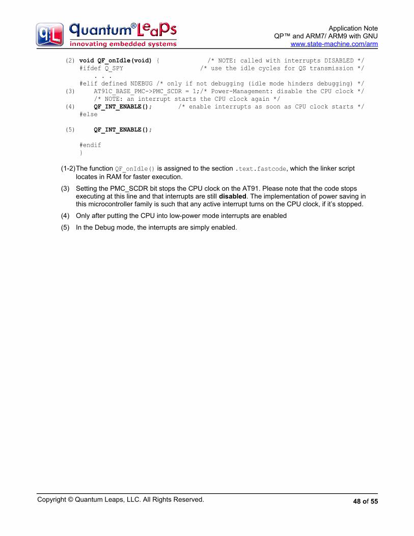
Copyright © Quantum Leaps, LLC. All Rights Reserved.
Application NoteQP™ and ARM7/ ARM9 with GNU
www.state-machine.com/arm
(2) void QF_onIdle(void) { /* NOTE: called with interrupts DISABLED */ #ifdef Q_SPY /* use the idle cycles for QS transmission */ . . . #elif defined NDEBUG /* only if not debugging (idle mode hinders debugging) */ (3) AT91C_BASE_PMC->PMC_SCDR = 1;/* Power-Management: disable the CPU clock */ /* NOTE: an interrupt starts the CPU clock again */ (4) QF_INT_ENABLE(); /* enable interrupts as soon as CPU clock starts */ #else
(5) QF_INT_ENABLE();
#endif }
(1-2)The function QF_onIdle() is assigned to the section .text.fastcode, which the linker script locates in RAM for faster execution.
(3) Setting the PMC_SCDR bit stops the CPU clock on the AT91. Please note that the code stops executing at this line and that interrupts are still disabled. The implementation of power saving in this microcontroller family is such that any active interrupt turns on the CPU clock, if it’s stopped.
(4) Only after putting the CPU into low-power mode interrupts are enabled
(5) In the Debug mode, the interrupts are simply enabled.
48 of 55

Copyright © Quantum Leaps, LLC. All Rights Reserved.
Application NoteQP™ and ARM7/ ARM9 with GNU
www.state-machine.com/arm
7 The QK PortThe QK ports show how to use QP™ state machine frameworks on the ARM processor with QK, which is a very lightweight, preemptive, priority-based kernel designed specifically for QF (see Chapter 10 in PSiCC2). You should consider the QK port if your application requires deterministic, real-time performance and also the application can benefit from decoupling higher-priority tasks from lower-priority tasks in the time domain. Perhaps the best way to learn about QK implementation for the ARM processor is to study Chapter 10 in PSiCC2. You might also read the article “Build Super Simple Tasker” [Samek+ 06], which explains the inner-workings of a single-stack preemptive kernel, like QK.
One of the biggest advantages of QK is that porting QK to a new microprocessor is very easy. In fact the QK port to ARM is almost identical to the simplest “vanilla” port described in Section 6. The main difference between the two ports, which is visible at the application level, is that you use QK_irq() and QK_fiq() “wrapper” functions for interrupt processing (instead of QF_irq() and QF_fiq(), respectively). The other slight difference is that you customize the idle loop processing in a different way than in the “vanilla” port. This section focuses only on the differences from the “vanilla” port.
7.1 Compiler and Linker Options Used
The QK port uses exactly the same compiler options as the “vanilla” QP port described in Section 6.
7.2 The QK Port Header File
The QK header file for the ARM, GNU toolchain is located in <qp>\ports\arm\qk\gnu\qk_port.h. This file specifies the interrupt enabling/disabling policy (QK critical section) as well as the interrupt and exception handling “wrapper” functions defined in assembly.
7.2.1 The QK Critical Section
The QK port uses the same critical section as the “Vanilla” port described in Section 6.1.1. The critical section is defined in the header file <qp>\ports\arm\qk\gnu\qf_port.h.
7.3 Handling Interrupts
This generic QK port to ARM can work with or without an interrupt controller, such as the Atmel’s Advanced Interrupt Controller (AIC), Philips’ Vectored Interrupt Controller (VIC), and others.
When used with an interrupt controller, the QK port assumes no “auto-vectoring”, which is described for example in the Atmel Application Note “Interrupt Management: Auto-vectoring and Prioritization” [Atmel 98b] (see also Section 6.2).
Figure 12 shows the interrupt processing sequence in the presence of an interrupt controller (Atmel’s AIC is assumed in this example). The ARM vector addresses 0x18 and 0x1C point to the assembler “wrapper”functions QK_irq and QK_fiq, respectively. Each of these “wrapper” functions, for example QK_irq, performs context save, switches to the SYSTEM mode, and invokes a C-level function BSP_irq (or BSP_fiq for the FIQ interrupt). BSP_irq encapsulates the particular interrupt controller, from which it explicitly obtains the interrupt vector. Because the interrupt controller is used in this case, it must be initialized with the addresses of all used interrupt service routines (ISRs), such as tickIRQ() shown inFigure 12. Please note that these ISRs are regular C-functions and not IRQ-type functions because the interrupt entry and exit code is already provided in the assembly “wrapper” functions QK_irq and QK_fiq.
49 of 55

Copyright © Quantum Leaps, LLC. All Rights Reserved.
Application NoteQP™ and ARM7/ ARM9 with GNU
www.state-machine.com/arm
Figure 12: Interrupt processing in the QK port to ARM with the Atmel’s AIC interrupt controller
7.3.1 The IRQ “Wrapper” Function for QK
The QK port provides interrupt “wrapper” function QK_irq() for handling the IRQ-type interrupts. The function is coded entirely in assembly, and is located in the file <qp>\qk\arm\qk\gnu\qk_port.s.
Listing 17: The QK_irq assembly wrapper for the QK port defined in qk_port.s.
/* use the special section (.text.fastcode), to enable fine-tuning * of the placement of this section inside the linker script */ .section .text.fastcode /***************************************************************************** * void QK_irq(void); */ .global QK_irq .func QK_irq .align 3 QK_irq: /* IRQ entry {{{ */ MOV r13,r0 /* save r0 in r13_IRQ */ SUB r0,lr,#4 /* put return address in r0_SYS */ MOV lr,r1 /* save r1 in r14_IRQ (lr) */ MRS r1,spsr /* put the SPSR in r1_SYS */
50 of 55

Copyright © Quantum Leaps, LLC. All Rights Reserved.
Application NoteQP™ and ARM7/ ARM9 with GNU
www.state-machine.com/arm
MSR cpsr_c,#(SYS_MODE | NO_IRQ) /* SYSTEM, no IRQ, but FIQ enabled! */ STMFD sp!,{r0,r1} /* save SPSR and PC on SYS stack */ STMFD sp!,{r2-r3,r12,lr} /* save APCS-clobbered regs on SYS stack */ MOV r0,sp /* make the sp_SYS visible to IRQ mode */ SUB sp,sp,#(2*4) /* make room for stacking (r0_SYS, r1_SYS) */
MSR cpsr_c,#(IRQ_MODE | NO_IRQ) /* IRQ mode, IRQ disabled */ STMFD r0!,{r13,r14} /* finish saving the context (r0_SYS,r1_SYS) */
MSR cpsr_c,#(SYS_MODE | NO_IRQ) /* SYSTEM mode, IRQ disabled */ /* IRQ entry }}} */
(1) LDR r0,=QK_intNest_ /* load address in already saved r0 */ (2) LDRB r12,[r0] /* load original QK_intNest_ into saved r12 */ (3) ADD r12,r12,#1 /* increment the nesting level */ (4) STRB r12,[r0] /* store the value in QK_intNest_ */
/* NOTE: BSP_irq might re-enable IRQ interrupts (the FIQ is enabled * already), if IRQs are prioritized by the interrupt controller. */ LDR r12,=BSP_irq MOV lr,pc /* copy the return address to link register */ BX r12 /* call the C IRQ-handler (ARM/THUMB) */
(5) MSR cpsr_c,#(SYS_MODE | NO_INT) /* make sure IRQ/FIQ are disabled */ (6) LDR r0,=QK_intNest_ /* load address */ (7) LDRB r12,[r0] /* load original QK_intNest_ into saved r12 */ (8) SUBS r12,r12,#1 /* decrement the nesting level */ (9) STRB r12,[r0] /* store the value in QK_intNest_ */(10) BNE QK_irq_exit /* branch if interrupt nesting not zero */
(11) LDR r12,=QK_schedPrio_(12) MOV lr,pc /* copy the return address to link register */(13) BX r12 /* call QK_schedPrio_ (ARM/THUMB) */(14) CMP r0,#0 /* check the returned priority */(15) BEQ QK_irq_exit /* branch if priority zero */
(16) LDR r12,=QK_sched_(17) MOV lr,pc /* copy the return address to link register */(18) BX r12 /* call QK_sched_ (ARM/THUMB) */
QK_irq_exit: /* IRQ exit {{{ /* IRQ/FIQ disabled--return from scheduler */ MOV r0,sp /* make sp_SYS visible to IRQ mode */ ADD sp,sp,#(8*4) /* fake unstacking 8 registers from sp_SYS */
MSR cpsr_c,#(IRQ_MODE | NO_IRQ) /* IRQ mode, IRQ disabled */ MOV sp,r0 /* copy sp_SYS to sp_IRQ */ LDR r0,[sp,#(7*4)] /* load the saved SPSR from the stack */ MSR spsr_cxsf,r0 /* copy it into spsr_IRQ */
LDMFD sp,{r0-r3,r12,lr}^ /* unstack all saved USER/SYSTEM registers */ NOP /* can't access banked reg immediately */ LDR lr,[sp,#(6*4)] /* load return address from the SYS stack */ MOVS pc,lr /* return restoring CPSR from SPSR */ /* IRQ exit }}}
51 of 55

Copyright © Quantum Leaps, LLC. All Rights Reserved.
Application NoteQP™ and ARM7/ ARM9 with GNU
www.state-machine.com/arm
Listing 17 shows the QK_irq() “wrapper” function in assembly. Please note that the interrupt entry (delimited with the comments “IRQ entry {{{” and “IRQ entry }}}”) and interrupt exit (delimited with the comments “IRQ exit {{{” and “IRQ exit }}}”) are identical as in the QF_irq() “wrapper” function. Please refer to the notes after Listing 17 for detailed explanation of these sections of the code. The following notes explain only the QK-specific additions made in the QK_irq() “wrapper” function.
(1-4)The QK interrupt nesting level QK_intNest_ is incremented and saved.
(5) Interrupts are disabled to access the QK interrupt nesting level QK_intNest_ and to call the QK scheduler.
(6-9)The current QK interrupt nesting level QK_intNest_ is decremented. Please note the use of the special version of SUBS in line (8), which sets the test flags if the nesting level QK_intNest_ drops to zero.
(10) The branch is taken when the QK interrupt nesting level QK_intNest_ is not zero. In this case the QK scheduler should not be called, because the IRQ is returning to a preempted IRQ, rather than the task level.
(11-13) The QK scheduler function QK_schedPrio_() is called via the BX instruction to determine the priority of the next task to run. The QK_schedPrio_() function can be compiled in ARM or THUMB mode, but perhaps using the ARM instruction set would deliver somewhat better performance.
(14) The priority, returned in r0, is tested against zero. Priority of zero means that no higher-priority task has been found, which would be above the priority of the preempted task.
(15) The branch is taken if the priority is zero (no scheduling is necessary).
(16) Otherwise scheduling is necessary, so the function QK_sched_() is called via the BX instruction. Thisfunction re-enables interrupts internally to launch a task, but it always returns with interrupts disabled. The QK_sched_() function can be compiled in ARM or THUMB mode, but perhaps using the ARM instruction set would deliver somewhat better performance.
7.4 Idle Loop Customization in the QK Port
As described in Chapter 10 of [PSiCC2], the QK idle loop executes only when there are no events to process. The QK allows you to customize the idle loop processing by means of the callback QK_onIdle(), which is invoked by every pass through the QK idle loop. You can define the platform-specific callback function QK_onIdle() to save CPU power, or perform any other “idle” processing (such as Quantum Spy software trace output).
NOTE: The idle callback QK_onIdle() is invoked with interrupts enabled (which is in contrast to QF_onIdle() that is invoked with interrupts disabled).
The following Listing 18 shows an example implementation of QK_onIdle() for the Philips LPC2xxx CPU.Other ARM-based embedded microcontrollers (e.g., Atmel’s AT91) handle the power-saving mode very similarly.
Listing 18: QK_onIdle() callback for the Philips LPC2xxx CPU
__attribute__ ((section (".text.fastcode")))void QK_onIdle(void) { PCON_bit.IDL = 1; /* go to idle mode to save power */}
52 of 55
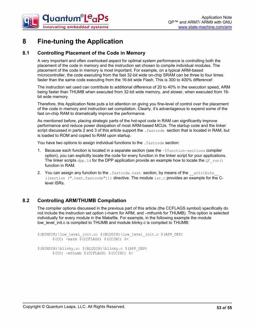
Copyright © Quantum Leaps, LLC. All Rights Reserved.
Application NoteQP™ and ARM7/ ARM9 with GNU
www.state-machine.com/arm
8 Fine-tuning the Application
8.1 Controlling Placement of the Code in Memory
A very important and often overlooked aspect for optimal system performance is controlling both the placement of the code in memory and the instruction set chosen to compile individual modules. The placement of the code in memory is most important. For example, on a typical ARM-based microcontroller, the code executing from the fast 32-bit wide on-chip SRAM can be three to four times faster than the same code executing from the 16-bit wide Flash. This is 300 to 400% difference!
The instruction set used can contribute to additional difference of 20 to 40% in the execution speed, ARM being faster than THUMB when executed from 32-bit wide memory, and slower, when executed from 16-bit wide memory.
Therefore, this Application Note puts a lot attention on giving you fine-level of control over the placement of the code in memory and instruction set compilation. Clearly, it’s advantageous to expend some of the fast on-chip RAM to dramatically improve the performance.
As mentioned before, placing strategic parts of the hot-spot code in RAM can significantly improve performance and reduce power dissipation of most ARM-based MCUs. The startup code and the linker script discussed in parts 2 and 3 of this article support the .fastcode section that is located in RAM, but is loaded to ROM and copied to RAM upon startup.
You have two options to assign individual functions to the .fastcode section:
1. Because each function is located in a separate section (see the –ffunction-sections compiler option), you can explicitly locate the code for every function in the linker script for your applications. The linker scripts dpp.ld for the DPP application provide an example how to locate the QF_run() function in RAM.
2. You can assign any function to the .fastcode.text section, by means of the __attribute__ ((section (".text.fastcode"))) directive. The module isr.c provides an example for the C-level ISRs.
8.2 Controlling ARM/THUMB Compilation
The compiler options discussed in the previous part of this article (the CCFLAGS symbol) specifically do not include the instruction set option (-marm for ARM, and –mthumb for THUMB). This option is selected individually for every module in the Makefile. For example, in the following example the module low_level_init.c is compiled to THUMB and module blinky.c is compiled to THUMB:
$(BINDIR)\low_level_init.o: $(BLDDIR)\low_level_init.c $(APP_DEP)$(CC) -marm $(CCFLAGS) $(CCINC) $<
$(BINDIR)\blinky.o: $(BLDDIR)\blinky.c $(APP_DEP)$(CC) -mthumb $(CCFLAGS) $(CCINC) $<
53 of 55

Copyright © Quantum Leaps, LLC. All Rights Reserved.
Application NoteQP™ and ARM7/ ARM9 with GNU
www.state-machine.com/arm
9 References
Document Location
[PSiCC2] “Practical UML Statecharts in C/C++, Second Edition”, Miro Samek, Newnes, 2008
Available from most online book retailers, such as amazon.com. See also: http://www.state-machine.com/psicc2.htm
[devkitPro] devkitPro website at SourceForge.net https://sourceforge.net/projects/devkitpro.
[devkitARM] devkitARM download from the devkitPro project at SourceForge.net
https://sourceforge.net/projects/devkitpro/files/devkitARM
[GNU-make for Windows] GNU make and related UNIX-style file utilites for Windows.
http://www.state-machine.com/resources/ -GNU_make_utils.zip
[Insight-GDB] Insight-GDB download from the devkitPro project at SourceForge.net
https://sourceforge.net/projects/devkitpro/files/Insight
[OpenOCD] OpenOCD on-chip debugger http://openocd.berlios.de
[Eclipse] Eclipse IDE for C/C++ Developers http://www.eclipse.org/downloads/
[Zylin-plugin] Zylin Embedded CDT plugin http://opensource.zylin.com/embeddedcdt.html
[Samek 07] “Building Bare-Metal ARM Systems with GNU”, Miro Samek, 2007
10-part article published on Embedded.com. Part 1available at: http://www.embedded.com/design/opensource/200000632
[AN-DPP] Quantum Leaps Application Note “Dining Philosophers Problem Example”
http://www.state-machine.com/resources/ -AN_DPP.pdf
[Samek+ 06b] “Build a Super Simple Tasker”, MiroSamek and Robert Ward, Embedded Systems Design, July 2006.
http://www.embedded.com/ showArticle.jhtml?articleID=190302110
[Seal 00] “ARM Architecture Reference Manual”, Seal, David, Addison Wesley 2000.
Available from most online book retailers, such as amazon.com. ISBN 0-201-73719-1.
[Atmel 98] Application Note “Disabling Interrupts atProcessor Level”, Atmel 1998
http://www.atmel.com/dyn/resources/ -prod_documents/DOC1156.PDF
[ARM 05] ARM Technical Support Note “Writing Interrupt Handlers”, ARM Ltd. 2005
www.arm.com/support/faqdev/1456.html
[Philips 05] Application Note AN10391 “Nesting of Interrupts in the LPC2000”, Philips 2005
www.semiconductors.philips.com/ -acrobat_download/ applicationnotes/ -AN10381_1.pdf
[Seal 00] “ARM Architecture Manual, 2nd Edition”, David Seal Editor, Addison Wesley 2000
Available from most online book retailers, such as amazon.com .
[ARM 06] “ARM v7-M Architecture Application Level Reference Manual”, ARM Limited
www.arm.com/products/CPUs/ARM_Cortex-M3_v7.html .
54 of 55

Copyright © Quantum Leaps, LLC. All Rights Reserved.
Application NoteQP™ and ARM7/ ARM9 with GNU
www.state-machine.com/arm
10 Contact Information
Quantum Leaps, LLC103 Cobble Ridge DriveChapel Hill, NC 27516USA
+1 866 450 LEAP (toll free, USA only)+1 919 869-2998 (FAX)e-mail: [email protected] WEB : http://www.quantum-leaps.com
http://www.state-machine.com
“Practical UML Statecharts in C/C++, Second Edition: Event Driven Programming forEmbedded Systems”, by Miro Samek, Newnes, 2008
55 of 55