Embed Size (px)
Citation preview
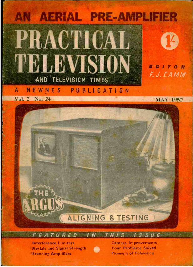
AN AERIAL PRL: AMP"
PRACTICAL TELEVISION
AND TELEVISION TIMES
NEWNES PUBLICATION 2 M ). 1 o FS 2
-t\ ( ALIGNING & TESTING
vn, FEATURED IN THIS ISSIJE Interference Lim itPrs Aerials and Signal Strength Scanning Amplifiers
Camera Improvement; Ycur Problems Solver! Pioneers cf Tchevision
r-
11 PRACTICAL TELEVISION May, 1952
W COHEN IIadio mid Televtision Components
Lino and EHT Transformer S to 6 Kv. removed from Chassis. Guaranteed. Recti- fier EY51.
Both items above 25e-
Line and Frame Scan Coils. Low Line High Impedance Frame re- moved from Chassis. Guaranteed.
Frans oscillator blocking
'.ranslormor.
4/6
PM Focus Unit. Any gift. or 12ín. tube, except' 216 Mazda 12, state tube. Similar to above, with front adjustment, IS1 -. PM Focus Unit for 5ra, I2in. Mazda.... ... Similar to above with :ron: adjustment, 1716.
MAINS TRANSFORMERS These transformers are all famous radio manufacturers' surplus and are fully inter -leaved, impregnated and guaranteed. Primary 200 -250 v. P. & P. on each, 116 extra. 300 -0.300, 100 mA, 6 volt 3 amp., 5 volt 2 amp., 1716.
320 -0-320, 120 mA, 6 volt 4 amp., 5 volt 2 amp., 231 -. 250-0-250, 100 mA, 6 v. 3 amp., 4 v. 3 amp., 4 v. 3 amp., 1716.
350 -0-350, 70 mA. 6 v. 2.5 amp., 5 v. 2 amp., 1416.
350-0 -350, 150 mA, 6 v.. 3 amp., 5 v. 2 amp., 2716.
280 -0-283, 80 mA, 6 v. 3, amp., 4 v. 2 amp., drop -through, 141 -. Semi- shrouded, drop- thro', 280-0-280 80 mA, 4 v. 6 amp., 4 v.
2 amp., 12)6. 350 -0-350, 120 mA, 4 v. 6 amp., 4 v. 3 amp., drop -through, 211 -. 350-0-350 100 mA. 4 v. 2 amp., 4 v. 4 amp. Upright or drop -through mounting, 161 -. Auto -wound, could be used in the Viewmaster, H.T. 280 volt, 360 mA, 4 volt 3 amp., 4 volt 3 amp., 2 volt 3 amp., 2 volt,.3 amp., 10!- plus 116 post and packing. 9in. White rubber mask with armour -plate glass ... ... 10!-
15in. Rubber mask ............ 151-
2m. Armour -plate glaze ... ... ... ... ... 41-
9in. Armour -plate glass ... 31-
Heater Transformer Pri 200 -250 v 6 v. 11 amp., 61- ; P. & P.
each 9d. TV. Chassis. Size 9) x 91 x 31. 18 gauge steel cadmium- plated, complete with five coil cans, size I ¡in. x lin., with ironed cored former. These are wound for television frequency, 616.
61in. Energised Television Speaker by Plessey. Field resistance 68 ohms with Humbucking coil. Will pass up to 300 ma. Require minimum 200 mla to energise. These are cheaper than a TV
choke, 916 each, 2 for IS! -. TERMS OF BUSINESS : CASH WITH ORDER.
DISPATCH OF GOODS WITHIN 3 DAYS FROM RECEIPT OF
ORDER.
Orders under £2 add 116. Under El add 11- pose and packing.
All enquiries and lists, stamped addressed envelope
23, HIGH STREET, ACTON, W.3. (UXBRIDGE ROAD) Acorn 5901
Heater transformer Pri. 230 -250 volt, Sec. 2 volt 21 amp. 5/.
Smoothing choke ISO mA 2 Henry, 3!6
.111®
The solder for a.!I
HOME TELEVISOI
CONSTRUCTOR SETS
Designers of television constructor sets know that the efficiency of their equipment depends on the solder used by the constructor- that's why they recommend Ersin Multicore for trouble -free, waste -
free soldering. Ersin Multicore, the only solder containing three cores
of extra -active, non -corrosive Ersin Flux, is obtainable from all leading radio shops. Ask for Cat. Ref. C.1.6018, 18 S.W.G. 60'40 High Tin Television and Radio Alloy. The size 1 Carton contains 37 feet of solder, costs 5/-.
ERSIN o Y
Ersin Multicore Solder In case of difitulty in obtaining supplies, please 'write to
MULTICORE SOLDERS LTD., MULTICORE WORKS, MAYLAMDS AVE., HEMEL HEMPSTEAD, IIERTS a BoxmOar 3536 (3 tines.)
-RADIO MAIL-5 4, RALEIGH STREET, NOTTINGHAM
INTRODUCING
A RESISTANCE- CAPACITY BRINE
AT 30 /- ONLY Note the following points
LESS THAN ONE FIFTH THE COST OF A COMMERC_AL INSTRUMENT OF SIMILAR RANGE.
THREE CAPACITY RANGES, TESTING UP TO -0 MFD. THREE RESISTANCE RANGES. TESTING UP TO 5
MEGOHMS.
EASILY UTY ÌUILA INSTRUCTIONS AND CRIT D LS SUPPLIED.
NO CALIBRATING NECESSARY AFTER ASSEMBLY.
ALL CALIBRATIONS. SWITCH RANGE MARKINGS, TER - MINAL FUNCTIONS, ETC., READY LAID OUT ON A HAND- SOME ESCUTCHEON COVERING THE ENTIRE OPERATING PANEL.
THIS IS THE FIRST TIME THAT AN INSTRUMENT OF THIS CALIBRE HAS BEEN AVAILABLE AT SUCH A LOW PRICE. ORDER NOW WHILE
SUPPLIES LAST
STAMP FOR LIST AND WITH ALL ENQUIRIES PLEASE
May, 1952 PRACTICAL TELEVISION 529
The
ELECTRONIC TESTMETER
This instrument has been developed to meet the growing demand for an instrument of laboratory sensitivity built in a robust and portable form, for use in conjunction with electronic and other apparatus where it is imperative that the instrument should present a negligible loading factor upon the circuit under test.
The instrument consists basically òf a balanced bridge voltmeter. It incorporates many unique features and a wide set of ranges so that in
' operation it is as simple to use as a normal multi -range testmetcr.
The instrument gives 56 ranges of readings as follows :- O.C. VOLTS : SmV. to 250V. (Input
Resistance 11.0 megohms.) 25mV. to 10.000V. (Input Resistance 110.0 megohms.)
O.C. CURRENT : 0.51,A. to I Amp. (2S0mV. drop on all ranges.)
A.C. VOLTS: 0.IV: to 2.500V. R.M.S. up to 2 Mcls. With diode probe external 0.IV. to 250V. R.M.S. Useful measurements can be made up to 200 Mcls. the applied voltage being limited to 100V. above 50 Mcls.
A.C. OUTPUT POWER : 5mW to 5 warts in 6 different load resist - ances'from 5 to 5,000 ohms
DECIBELS : -10db. to +20db.
CAPACITANCE : .02011,F. to 50pF.
RESISTANCE: 0.2 ohm to 10 megohms.
INSULATION : 0.1 megohm to 1,003 megohms.
tt L Size : 121in . x 9ins. x 51 ins eG1 Weight : 12í16s.
The instrument operates on A.C. mains, 100 -130V. and 200- 260V., SO -60 cls.
11 rite for fully descriptive pamphlet.
The instrument is quickly set up for any of the various tests to be undertaken, a single range selector switch auto- matizally removing from the circuit any voltages and controls which are not required for the test in question.
Sole Proprietors and Manufacturers:
7 /1e AUTOMATIC COIL WINDER & ELECTRICAL EQUIPMENT CO.,LTD. WINDER HOUSE DOUGLAS STREET LONDON S.W.I Telephone: VICTORIA 3404/9 E.T.M.3 r ó
EVERYBODY IS BUILDING THE VIEWMASTER! All components in stock and sold
separately Full Viewmaster price list available on request.
Model A for use in London and the Home Counties. B for Sutton Coldfield, C for Holme Moss, D for Kirk o' Shotts, E for Wenvoe.
Sound /vision chassis Time base chassis
.. 18/6 18/6
WESTINGHOUSE RECTIFIERS 36EHT100 141336 .. 14A86 WX3 WX6 36EHT45 36EHT50 . .
29/4 11 /8 20/4
3/9 2318 26/1
T.C.C. VISCONOL CONDENSERS .001 mfd. CP55Q0 4/6 .001 mfd. CPSSVO 7;6 All T.C.C. Condensers for the View - master available at listed prices from stock.
WB /PLESSEY Tube supports .. 21/6 Line E.H.T. trans. .. 32/6 Frame trans, .. .. 25,6 Boost choke .. .. 5/9
Scanning coils Heater trans. WB /103
W13/103A .. Focus ring.. .. .. Main choke .. ..
Width control Supporting bracket
All post extra.
33'3 42,- 52!6 22/6 15'6 10,,
WEARITE COILS. For all models. A.B.C.D.E. 10 Coils .. .. .. 20'- 4 Filter coils .. .. .. 8'- L9 choke .. .. 2/-
State model when ordering.
CONSOLE CABINETS for 12in. C.R. tubes, medium walnut finish. LASKY'S PRICE, £8,10;0. Adaptor frames for 9in. or l0in. C.R. tubes available.
Send 2._.d. stamp for illustration.
Television for the home constructor at its finest.
Send to-day for the CONSTRUCTION ENVELOP E, a 32 -page booklet crammed with top -rate information and all the necessary data, also 8 full-size working drawings and stage bs stage wiring instructions. PRICE A, B & E. 5/- PER COPY. C & D, 7/6 PER COPY. Post 4d. extra.
LASKY'S RADIO 370, HARROW ROAD, PADDINGTON,
(Lasky s (Harrow Road) Ltd.) ' LONDON, W.9. (Opposite Paddington Hospital.) 'Phone : Cunningham 1979 and 7214. Hours : Mon. to Sat., 9.30 a.m. to 6 p.m. Thurs.. half -day. TERMS : Pro Forma, Cash With Order, or C.O.D. on post items only. Postage and packing extra, unless otherwise stated.
All goods fully insured in transit.

530 PRACTICAL TELEVISION
CONDENSERS The abbreviated ranges of two
popular types given here are repre- sentative of the wide variety of T.C.C. Condensers available.
" VISCONOL CATHODRAY " CONDENSERS Cap. Range: 0005mfd. to I mfd.
Voltage Range: 750 to 25,000 at 60 'C.
Cap. Max. Wkg. amens. (Overall) in µF. at 60`C. Length I Dia.
'001 '001 01 'I '25
25,000 6,000
12,500 6,000 7,000 5,000
5f;in. 22 in. 3 in. 3 in. 6) in. 5¡ in.
Type No.
Ipin. I CP.57.HOO in.
'
CP.55.QO I Lin. CP.56.VO
.1 %* in. CP.56.QO 2 in. CP.58.QO 2; in. CP.59.MO
(Regd.) SUPER TROPICAL MINIATURE " METALMITES "
lin Aluminium Tubes)
Capacity Wkg. Volts D.C. Dimensions
at 71`C. at 100'C. Length I Dia.
350 pin. '2 in. 350 pin. 2 in. 200 lin. '2 in. 200 :in. '22in. 120 Ein. 22in. 200 ;;in. '34in.
0002 500 '0005 500 '001 350 '002 350 '005 200 '01 350
Type No.
CPI 105 CPI IOS CPI ION CPIIIN CPI 11H CPI 13N
THE TELEGRAPH CONDENSER CO. LTD. Radio Division : North Acton, London, W.3. Tel: Acorn 0061
Home- built TV for ALL !
A' "A°rb y«at15'x <vev s;7 YtIlH 44,044 rt,
aH3JienYh4rRoie:ox
n,4 a. tA ta ,
arRro1R .«oat+
Fla MÑ!' c
HANE rr'HA¡y4
Now you can build the famous ' View Master' for reception from any of the B.B.C. transmitters-including Kirk o'Shotts and Wenvoe. 70,000 ' View Master' instruction envelopes have already been sold, and we have received many "enthusiastic letters from home constructors praising the performance this .... remarkable set gives:,
Your local radio. shop can supply,' View Master '.envelopes and components: in case of difficulty, the envelope will be sent direct on receipt of. P.O. for 8/-. 'VIEW MASTER,' 10, NORFOLK ST., LONDON, W.C.2
11111 2111111121i1 "TELEVISION TIMES"
Editor : F. J. CAMM
Editorial and Advertisement Offices: " Practical Television." George Newnea, Ltd., Tosser House, Southampton Street, Strand, W.C.S. 'Phone: Temple Bar 4363.
Telegrams: Newnes, Rand, London. Rogtstered at the G.P.O. for transmission by Canadian Magazine Post.
Vol. 2. No. 24 EVERY MONTH MAY, 1952
Televiews THE EVER GROWING AUDIENCE
APPROXIMATELY 1,386,000 television licences were current in Great Britain and Northern Ireland at the end of February of this year,
and for the second month in succession the number of television licences has increased by more than 100,000. Thus, in the space of two years, television licences have increased by over 1,000,000. The total number of broadcast receiving licences, including the television licences, is 12,637,000. Our enquiries show that whilst the number of receiving licences for sound - broadcast receivers continues to rise, the amount of time spent in listening to radio programmes is de- creasing, and the time spent in viewing continues to rise. Viewers are an ever growing audience, and it seems reasonably certain that at the present rate of accretion there will be 5,000,000 viewers within the next five years. Any two television programmes are seen by more people than visit a successful theatrical show in the whole of a year. Sales of TV receivers now exceed the sale of broadcast receivers.
The statistics given do not take into account the number of viewers, considered to be at least 100,000, who have not taken out licences.
TV MAINTENANCE COSTS
A READER asks us whether his maintenance costs for a commercial TV receiver over the
last two years, which have amounted to £16 4s., are exceptional. He says that during that period he has had to replace 12 valves and one C.R. tube. Upon protesting to the makers he was informed that this may be considered as normal for any type of receiver. We can: assure the reader that this is not so. Our own " P.T. " receiver has been in regular use for the past two years and the replacements have been nil.
- Valves, being consumable items, are considered by the manufacturers as items which should be replaced by the user, as obviously the number of hours the receiver is in use cannot be covered by an extensive guarantee, although manufacturers do,, as a fact, guarantee tubes and valves for a period of at least six months. It is our experience that tubes retain their characteristics for two years at least. HoweVCr, we invite our readers to relate their experi- ences in our correspondence columns.
PURCHASE TAX RELIEF SCHEME
MR. J. STANLEY. of Colliers Wood, has pro - pöunded a scheme for the relief of Purchase
Tax on TV tubes. He argues that it is a hardship when, just outside the guarantee period and having paid a considerable sum in Purchase Tax when buying the receiver, a further quite large sum must-be paid in tax should a new tube be required. He has sub- mitted his scheme to a number of newspapers and periodicals and also to a Member of Parliament. Briefly, he suggests that the G.P.O. licence form should be printed with an additional, coupon fixed by the normal perforation method this coupon containing the licence number, date òf isstie and name and address of the purchaser. By presenting this slip to the retailer Purchase Tax can be remitted from the sale of one TV tube, the retailer forwarding the slip through the proper channels for refund, and the slip being filed against the TV licet'tce record. The sponsor of the scheme says that there is no likelihood of a black market in these slips because of the possibility of their own set failing. As all tubes are guaranteed for six months, it could be made a rule that the slip is only valid for three months after issue, unless a licence had been held previously. The scheme would permit one tube per year per licence.
On the face of it the scheme would appear to have merit, but we foresee a number of snags in its opera- tion. Unscrupulous people would find plenty of loopholes, for it is not true to assume that a new tube is required every year by every viewer.
" TELEVISION PRINCIPLES AND PRACTICE" WE have just published an important new hand-
book entitled " Television Principles and Practice." It costs 25s., or 25s. 8d. by post, and contains 215 pages. The chapters are : The BBC Television System ; The Television Camera ; From Transmitter to Receiver ; Projection Receivers ;
Stereoscopic and Colour Television ; Time Bases ;
D.C. Receivers : Aerials ; A London -Birmingham Converter ; Servicing ; Interference : A Pattern Generator ; Choosing a Receiver ; the Beveridge Report ; Dictionary of Television Terms, and a fully cross -referenced index. The edition is neces- sarily limited by the paper position, so copies should be ordered without delay. -F. J. C.
532 PRACTICAL TELEVISION May,
A REVIEW OF SEVERAL COMMERCIAL SYSTEMS
By S. A. Knight
(Continued from page 493 April issue.
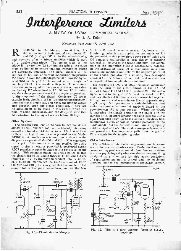
REFERRING to the Murphy circuit (Fig. 11) the suppressor is built around two diodes D1 and D2 (a single DD 41 in the actual circuit),
and operates after a triode amplifier which is part of a double -diode- triode. The anode load of the triode RI is very low (22 kQ) but the gain of the stage must be limited to ensure that the interference pulses are adequately retained. The signal appears at the cathode of D1 and at normal modulation frequencies the anode follows the cathode potential ; thus the signal is applied to the grid of the output valve through the coupling C4R4. The anode voltage of D1 is derived from the audio signal at the anode of the output valve, rectified by D2 whose load is R3, D1 and R2 in series, and the voltage present across C3 is directly proportional to the amplitude of the signal. Condenser C2 (stray capacity in the circuit) thus has its charging rate dependent upon the signal amplitude, and hence the limiting action also depends upon the signal amplitude. There are no adjustments to be made to this circuit, which is a point of some importance, and the designers state that no distortion to the signal occurs below 10 kc /s.
Other Systems The possible variations of the basic limiter circuits are
almost without number, and two particularly interesting circuits are found in G.E.C. receivers. The first of these is shown in Fig. 12, and is incorporated in the Model BT109IA. A double -diode is used but is shown in the diagram as separate diodes DI and D2. D2 is connected to the grid of the output valve and rectifies the audio signal so that a negative potential is developed across R2C3 practically equal in value to the peak level of the signal. This potential biases the anode of D1 so that the signals fed to its anode through CIRI and C2 are insufficient to allow the valve to conduct. On the arrival oja pulse of interference the time constant of R2C3 (10 Mo and 0.01 µF) is so great that the anode of D2 cannot follow the pulse wave -form, and so the bias
Fig. 11.- Circuit due to Murphy.
level on Dl anode remains steady. As, however, the interfering pulse is also applied to the anode of 131 the potential at this point rises above cut -off value and Dl conducts and applies a large degree of negative feedback to the grid of the triode amplifier. The ampli- tude of the interfering pulse is consequently reduced. In the absence of noise D1 is maintained in a non- conducting condition not only by the negative potential at the anode, but also by a standing bias developed across R3 in the cathode of the triode, and so distortion on signals of low amplitude is minimised.
On Models BT7092 and 7094 the noise suppressor takes the form of the circuit shown in Fig. 13 and utilises a diode DI-and an R.F. pentode VI. The audio signal is fed to the grid of VI and the anode of D1, and the cathodes of the two valves are connected together through an artificial transmission line of approximately 5 f1S delay. VI operates as a cathode -follower, and under no signal conditions DI anode is biased by the potentiometer RI to just conduct. When the circuit is operating the signals appear at the anode and the cathode of D1 at approximately the same level but with a 5 µS phase -time delay due to the action of the delay line. Interference pulses appear as positive potentials at the diode anode, but the cathode cannot rise in sympathy' until the lapse of 5 itS. The diode consequently conducts and provides a low impedance path from the grid of VI to chassis for the interfering pulse.
Vision Interference The problem of interference suppression on the vision
side of the receiver is rather easier of solution than is the corresponding problem on sound. Interference on vision is not as psychologically objectionable as the same thing produced as a noise, and for this reason conditions of suppression are not as critical ánd the maximum tolerable limit of the interference is somewhat greater.
Fig. 12.-This is a good scheme -found in C.L.C. receivers.

May; 1952. PRACTICAL
For once in a while this fact is a fortunate one from the designer's point of view, as it would be no simple matter to design a limiter that would follow the video waveform as those so far discussed follow the audio waveform, because in general the pulse character of the interference is little different from the overall shape of the video signal. The only solution lies in a simple form of amplitude chopping that will limit the interfering
Fig. 13.- Another arrangement used by G.G.C.
pulses to the maximum (peak white) level of the signal, anything below this level being accepted along with the picture modulation.
An interfering pulse of short duration should theoretic- ally only produce a small bright spot on the tube screen, but in practice the electron beam is defocused by the overloading produced by the noise when the tube is driven far above normal peak white level. The spot then becomes a large blob and a large area of the picture is obliterated. By limiting the interfering peaks to the maximum white level of the picture, focus is retained and the only effect on the screen is the appearance of extremely small white spots that do little or nothing to mar the image.
A simple diode limiter may be included in the circuit immediately after the detector, but in general it is connected directly to the tube input electrodes or at trie output of the video amplifier, whichever happens to be most convenient. A thoroughly typical circuit is shown in Fig. 14, and is so used in Vidor televisi9n receivers. One half of the double -diode valve acts at the normal vision detector and the output is passed through the filter C11,1 to the grid of the video amplifier. The output at the anode of this valve is returned to the anode ohe other diode, the cathode of the diode being taken to the junction of R1 and R2 connected across the H.T. supply source. Normally the diode is held in a non- conducting condition, the cathode potential being more positive than the anode ; on reception of a high amplitude interfering pulse the video amplifier anode swings to- wards the potential of' the H.T. supply and the limiter conducts, thus providing a low impedance path for the interfering peak.
The values assigned to Rl and R2 in this circuit are chosen, in relation to the maximum possible positive excursions of the video signal at the anode of the video amplifier, so that the diode cathode voltage just exceeds that at the anode when peak white signals are being handled. R1 and R2 could, of course, be replaced by a
TELEVISION 533
variable control so that the actual level at which the diode conducts is adjustable, and in some receivers this is done. This refinement takes care of alterations in the peak white level introduced by adjustments to the con- trast control, but in general the setting of such limiters is not critical over a wide range of contrasts and the fixed potentiometer for cathode bias is sufficiently effective. When the video amplifier is fed from the cathode of the
R2 27oKf1
Po
F.g. 14.-This is a Vidor arrangement.
detector, i.e., with positive -going signals, the limiter diode must be reversed also, the cathode being connected to the video amplifier anode.
A modification of the circuit is found in some H.M.V. and Cossor receivers ; Fig. 15 shows the circuit used bn H.M.V. Models 1805 and 1806. Here the cathode of the limiter diode D1 is biased positively with respect to the anode by the setting of the potentiometer Rl and so is rendered normally non -conductive. The cathode also couples to the anode of the video amplifier through a condenser Cl of 0.1 pF capacity. When interference occurs and the signal exceeds the peak white level set by R1 the anode of the diode limiter goes positive and the valve conducts. An 180 deg. out -of- phase signal is then applied through Cl through D1 to the grid of the video amplifier and the interference is neu- tralised. On Cossor models a negative detector output necessitates the reversal of the limiter diode and Cl has a value of 0.5 1IF.
Fig.15.- H.M.V. and Cossor both make use of this idea.
1
3
534 PRACTICAL TELEVISION
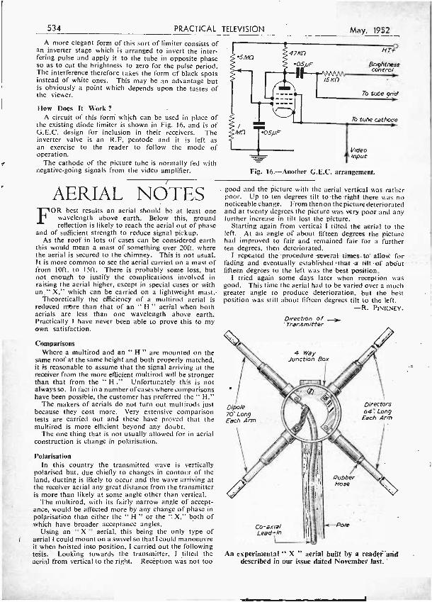
A more elegant form of this sort of limiter consists of an inverter stage which is arranged to invert the inter- fering pulse and apply it to the tube in opposite phase so as to cut the brightness to zero for the pulse period. The interference therefore takes the form of black spots instead of white ones. This may be an advantage but is obviously a point which depends upon the tastes of the viewer.
How Does It Work ?
A circuit of this form which can be used in place of the existing diode limiter is shown in Fig. 16, and is of G.E.C. design for inclusion in their receivers. The inverter valve is an R.F. pentode and it is left as an exercise to the reader to follow the mode of operation.
The cathode of the picture tube is normally fed with negative -going signals from the video amplifier.
47Kf1
OS/uF
11--,SK °
May, 1952
HT+
Brightness contro/
70-
To tube grid
To tube cathode
Video input
Fig. 16.- Another G.E.C. arrangement.
AERIAL NOTES FOR best results an aerial should be at least one
wavelength above earth. Below this, ground reflection is likely to reach the aerial out of phase
and of sufficient strength to reduce signal pickup. As the roof in lots of cases can be considered earth
this would mean a mast of something over 20ft. where the aerial is secured to the chimney. This is not usual. It is more common to see the aerial carried on a mast of from loft. to 15ft. There is probably some loss, but not enough to justify the complications involved in raising the aerial higher, except in special cases or with an "X," which can be carried on a lightweight mast.
Theoretically the efficiency of a multirod aerial is reduced wore than that of an " H " aerial when both aerials are less than one wavelength above earth. Practically I have never been able to prove this to my own satisfaction.
Comparisons Where a multirod and an " H " are mounted on the
same roof at the same height and both properly matched, it is reasonable to assume that the signal arriving at the receiver from the more efficient multirod will be stronger than that from the " H ." Unfortunately this is not always so. In fact in a number of cases where comparisons have been possible, the customer has preferred the " H."
The makers of aerials do not turn out multirods just because they cost more. Very extensive comparison tests are carried out and these have proved that the multirod is more efficient beyond any doubt.
The one thing that is not usually allowed for in aerial construction is change in polarisation.
Polarisation In this country the transmitted wave is vertically
polarised but, due chiefly to changes in contour of the land, ducting is likely to occur and the wave arriving at the receiver aerial any great distance from the transmitter is more than likely at some angle other than vertical.
The multirod, with its fairly narrow angle of accept- ance, would be affected more by any change of phase in polarisation than either the " H " or the " X," both of which have broader acceptance angles.
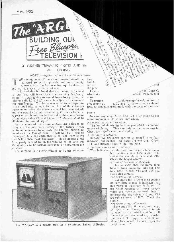
Using an " X " aerial, this being the only type of aerial I could mount on a swivel so that I could manoeuvre it when hoisted into position, I carried out the following tests. Looking towards the transmitter, I tilted the aerial from vertical to the right. Reception was not too
good and the picture with the aerial vertical was rather poor. Up to ten degrees tilt to the -right there was no noticeable change. From then on the picture deteriorated and at twenty degrees the picture was very poor and any further increase in tilt lost the picture.
Starting again from vertical I tilted the aerial to the left. At an angle of about fifteen degrees the picture had improved to fair and remained fair for a further ten degrees, then deteriorated.
I repeated the procedure several times to allow for fading and eventually established that -a tilt of abut fifteen degrees to the left was the best position.
I tried again some days later when reception was good. This time the aerial had to be varied over a much greater angle to produce - deterioration, but the best position was still about fifteen degrees tilt to the left.
-R. PINKNEY.
Direction of Trersmitter
4 Way Junction Box
Dipole 70' Long Each Arm
Directors 64' Long
Each Arm
Co -axial Lead -/n
lí
Po/e
An experimental " X " aerial built by a reader and described in our issue dated November last.
May, 1952
---- TELEVISION
BUIL®ING OUIN 9G7 0,
Ç
.6
Gor° -1
`sV9 ' VV.% 9d A ce
3.- FURTHER TRIMMING NOTES AND SI!
FAULT FINDING
NOTE :- Reprints of the Blueprint and instru,
THE tuning cores of the vision receiver should be adjusted so as to provide maximum quality starting with the last one feeding the detector
and working back to the aerial coil. It will probably be found that the picture is inclined
to jump and will have black lines running diagonally across it. This is due to sound breakthrough, and the rejector coils L6 and L7 should be adjusted to eliminate this interference. To obtain maximum sound rejection it is a good idea to wait for the close of the evening's transmission when the vision channel has been cut off and the sound channel is radiating the news bulletin. A pair of earphones can be inserted in the anode circuit of the video valve V6, and L6 and L7 adjusted so as to eliminate the sound signal.
As the cores of the vision receiver are adjusted to bring out the maximum quality in the picture it will be found necessary to advance the contrast control to counteract the loss of gain. It will be found best to " stagger " tune the coils, that is, to tune them above and below their peak frequency. This staggering has
been partly catered for in the winding of the coils but the quality can be further improved by continuing the process.
The method to be employed is to adjust all cores
level and L turns. the pros
Final .
which is s
noon.
t) N 7 O
°'i% y . 9 7 ¡¡ßGx.A y`,0¡d óé iN°O o 3
° 0i6 -7 ooG G OJ ó hse i G .GAA.yVJN,iC y á i °:')P% % tiJ
7 0-Ey O\ ñÚÚd
, afiíi
test Card C. .rneen 10 a.m. and
To receive ,dál, turn up the volume control and simply at :, T2 and T3 for maximum volume, final adjustmei..s being made with the cores of the coils.
Faults In case any snags arise, here is a brief guide to the
more common faults which may occur. No sound ; no vision; no raster.
The fault obviously lies in some part which is common to the whole unit. That can only be the mains supply. Check the on /off switch, mains plug, etc.
A spot only is obtained. Reduce the brilliance control at once ! The fault
indicates that neither time hases are working. Check H.T. and filament lines in the time base.
A horizontal line only is obtained. This indicates that the line time base is functioning
but the frame time base is not. Ex- amine the circuits of V17 and V I8. Check the height control. A vertical line only is obtained.
This indicates that the frame time base is functioning but not the tine time base. Check V15 and V16 and associated circuits. The raster is too narrow.
Take out V16 ; if there is no change or very little change it indicates that this valve or its circuit is faulty. If the raster becomes still more narrow when this valve is removed then it indicates that the valves V16 and VI5 are being starved of H.T. Check the supply. The raster is not tall enough.
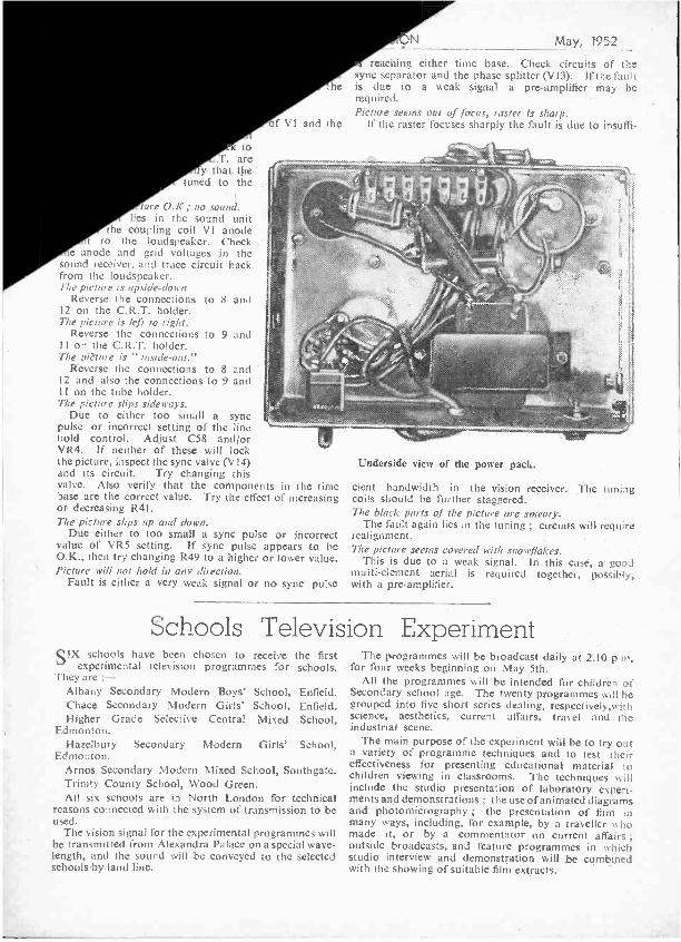
Take out V18 ; if there is no change; or very little change, then it is this valve or its circuit which is at fault. If the raster becomes markedly shorter, then the H.T. supply is at fault and should be checked. Do not forget the height control l The "Argus" in a cabinet built for it by Messrs Talton, of Rugby.
to . are
y that the tuned to the
tore O.K.; no sound. lies in the sound unit
the coupling coil VI anode to the loudspeaker. Check
e anode and grid voltages in the sound receiver, and trace circuit back from the loudspeaker. The picture is upside -down
Reverse the connections to 8 and 12 on the C.R.T. holder. The picture is left to right.
Reverse the connections to 9 and 11 on the C.R.T. holder. The pit1ue is "inside- out."
Reverse the connections to 8 and 12 and also the connections to 9 and 11 on the tube holder. The picture slips sideways.
' Due to either too small a sync pulse or incorrect setting of the line hold control. Adjust C58 and /or VR4. If neither of these will lock the picture, inspect the sync valve (V14) and its circuit. Try changing this valve. Also verify that the components in the time base are the correct value. Try the effect of increasing or decreasing R41. The picture slips up and down.
Due either to too small a sync pulse or incorrect value of VR5 setting. If sync pulse appears to be O.K., then try changing R49 to a higher or lower value. Picture will not hold in any direction.
Fault is either a very weak signal or no sync pulse
f V1 and
N May, 1952
reaching either time base. Check circuits of the sync separator and the phase splitter (V13). If the fault
e is due to a weak signal a pre -amplifier may be required. Picture seems out of focus, raster is sharp.
the If the raster focuses sharply the fault is due to insuffl-
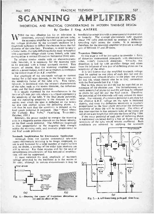
Underside view of the power pack.
dent bandwidth in the vision receiver. The tuning coils should be further staggered. The black parts of the picture are smeary.
The fault again lies in the tuning ; circuits will require realignment. .
The picture seems covered with snowflakes. This is due to a weak signal. in this case, a good
multi -element aerial is required together, possibly, with a pre- amplifier.
Schools Television Experiment SIX schools have been chosen to receive the first
experimental television programmes for schools. They are
Albany Secondary Modern Boys' School, Enfield. Chace Secondary Modern Girls' School, Enfield. Higher Grade Selective Central Mixed School,
Edmonton. Hazelbury Secondary Modern Girls' School,
Edmonton. Arnos Secondary Modern Mixed School, Southgate. Trinity County School, Wood Green. All six schools are in North London for technical
reasons connected with the system of transmission to be used.
The vision signal for the experimental programmes will be transmitted from Alexandra Palace on a special wave- length, and the sound will be conveyed to the selected schools by land line.
The pogrammes will be broadcast daily at 2.10 p.m. for four weeks beginning on May 5th.
All the programmes will be intended for children of Secondary 'school age. The twenty programmes will be grouped into five short series dealing, respectively ors ith science, aesthetics, current affairs, travel and the industrial scene.
The main purpose of the experiment will be to try out a variety of programme techniques and to test their effectiveness for presenting educational material to children viewing in classrooms. The techniques will include the studio presentation of laboratory experi- ments and demonstrations ; the use of animated diagrams and photomicrography ; the presentation of film in many ways, including, for example, by a traveller who made it, or by a commentator on current affairs ; outside broadcasts, and feature programmes in which studio interview and demonstration will, be combined with the showing of suitable filtt3 extracts.
May, 1952
SCA PRACTICAL TELEVISION 537
N ING AMPLIFIERS THEORETICAL AND PRACTICAL CONSIDERATIONS IN MODERN TIME -BASE DESIGN
By Gordon J. King, A.M.I.P.R.E.
WITH the now obsolete (as far as television is
concerned, anyway) electrostatic picture tube, the scanning amplifier is called upon to magnify
the voltage generated by the sawtooth oscillator to a magnitude sufficient to deflect the electron beam the full diameter of the tube face. Therefore, in order to secure a linear master, the tube deflecting plates must be supplied with a sawtooth voltage which varies linearly with time during either a vertical (frame) or horizontal (line) scan.
To achieve similar results with an electromagnetic tube, however, it is necessary for the scanning coils to be provided with a linear sawtooth current. This means, of course, that the scanning amplifier must deliver a power output, and in some respects is analogous to the output stage of an A.F. amplifier.
The amplitude of the saw -tooth voltage or current needed for a full scan depends, in the former case, on the sensitivity factor of the tube only. This factor, however, is connected with the inherent characteristics of the tube, such as the screen diameter, the deflection angle and the final anode potential.
It is usually expressed by the manufacturers in the form of x)V mm. per volt, where x is a figure representing the sensitivity of the tube, V the final anode potential, and the operating sensitivity is the distance in milli- metres over which the spot is deflected on the screen for one volt applied across the deflecting plates. It will thus be seen that the sensitivity is reduced as the final anode potential is increased. (See " More About the Cathode Ray Tube," PRACTICAL TELEVISION, October, 1951.)
Similarly, the power needed to energise the scanning coils in a magnetic system depends on the beam velocity, or the final anode potential. The deflection magnitude is thus proportional to the magnetic field strength within the scanning coils, and inversely proportional to the final anode potential.
Sawtooth Amplification for Electrostatic Application Although from the current commercial television
aspect electrostatic scanning is no longer employed, its use is still favoured by a large number of experimenters and, no doubt, a number of the older type receivers are still in service. For these reasons and for the sake of completeness consideration of this method of amplifica- tion will not be suppressed.
In most instances the peak amplitude of sawtooth voltage generated by the oscillator is in the region of 50 volts, although in certain circumstances it may be
Anal Anode
(a)
(C) Horizonte/ saw-toot/ vo/tage -
T (b) Vert/cal - baw-toOth
vo/tage -I (b)
Fig. 1.- Showing the cause of trapezium distortion at (a) and its effect at (b).
beneficial to accept less with a consequential improvement in linearity. The average electrostatic tube requires about 750 volts peak -to -peak to produce a deflection spreading right across the screen. It is necessary, therefore, for the scanning amplifier to provide a voltage gain of between 15 and 20 times.
Trapezium Distortion At this stage it will be instructive to consider a form
of distortion encountered principally with electrostatic tubes, namely trapezium distortion. Virtually, this distortion is tied up with amplifier design and arises from the influence of one pair of deflecting plates on the sensitivity of the other.
It is well known that the amplified sawtooth voltage must be applied to one plate of each pair (a) and (h) (horizontal and vertical) relative to the other two plates (c) and (d), which should also be in D.C. connection with the final anode (see Fig. 1 (a)).
Due to this, plates (c) and (d) can be regarded as an extension of the electron gun. The instantaneous saw- tooth potential of plates (a) and (b) will thus be reflected to plates (c) and (d) and the final anode. Therefore. the potential.of this electrode will vary around its mean value. For instance, if a positive potential is on plate (a) the effective E.H.T. voltage on the tube is increased slightly, and since the deflection sensitivity is inversely proportional to the final anode potential the deflection sensitivity of plate (b) will be reduced. The effect of this inter -reaction is that opposite sides of the raster are not of the same length but will take the form of Fig. 1 (b).
If the mean potential of each pair of deflecting plates is maintained unaltered during a line or frame scan the sensitivity of the tube would remain unaffected. Such conditions are achieved by applying the sawtooth
F nal Anode)
Bi HT+
Sync,
(b) 9
(a) Fig. 2. -A self -linearising push -pull time -base.
538 PRACTICAL
deflecting voltages in push -pull so that the potential of one plate' of a pair swings positivé whí'e the other swings negative by an equal amount.
Push -pull Time -base Amplifiers Amplifiers employed for this purpose are usually R.C.
coupled throughout and operate under strictly linear conditions. This often means that the H.T. voltage necessary to prevent distortion reaches a magnitude similar to the peak -to -peak voltage desired from the output.
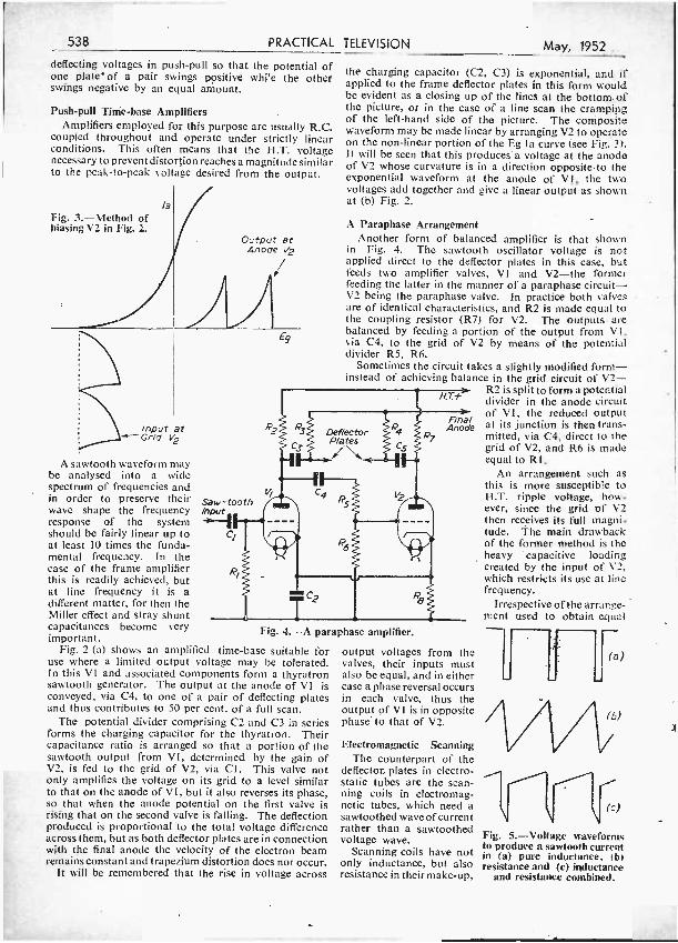
la Fig. 3.- Method of biasing V2 in Fig. 2.
Output at Anode
/v2 í
TELEVISION May, 1952
the charging capacitor (C2, C3) is exponential, and if applied to the frame deflector plates in this form would be evident as a closing up of the lines at the bottom of the picture, or in the case of a line scan the cramping of the left -hand side of the picture. The composite waveform may be made linear by arranging V2 to operate on the non -linear portion of the Eg Ia curve (see Fig. 3). It will be seen that this produces a voltage at the anode of V2 whose curvature is in a direction opposite to the exponential waveform at the anode of VI, the two voltages add together and give a linear output as shown at (b) Fig. 2.
A Paraphase Arrangement Another form of balanced amplifier is that shown
in Fig. 4. The sawtooth oscillator voltage is not applied direct to the deflector plates in this case, but feeds two amplifier valves, V1 and V2 -the former feeding the latter in the manner of a paraphase circuit - V2 being the paraphase valve. In practice both valves are of identical characteristics, and R2 is made equal to the coupling resistor (R7) for V2. The outputs are balanced by feeding a portion of the output from V1, via C4, to the grid of V2 by means of the potential divider R5, R6.
Sometimes the circuit takes a slightly modified form - instead of achieving balance in the grid circuit of V2-
R2 is split to form a potential divider in the anode circuit of VI, the reduced output at its junction is then trans- mitted, via C4, direct to the grid of V2, and R6 is made equal to R1.
An arrangement such as this is more susceptible to H.T. ripple voltage, how- ever, since the grid of V2 then receives its full magni- tude. The main drawback of the former method is the heavy capacitive loading created by the input of V2, which restricts its use at line frequency.
Irrespective of the arrange- ment used to obtain equal
input at Grid V2
A sawtooth waveform may be analysed into a wide spectrum of frequencies and in order to preserve their wave shape the frequency response of the system should be fairly linear up to at least 10 times the funda- mental frequency. In the case of the frame amplifier this is readily achieved, but at line frequency it is a different matter, for then the Miller effect and stray shunt capacitances become very important.
Fig. 2 (a) shows an amplified time -base suitable for use where a limited output voltage may be tolerated. In this VI and associated components form a thyratron sawtooth generator. The output at the anode of VI is conveyed, via C4, to one of a pair of deflecting plates and thus contributes to 50 per cent. of a full scan.
The potential divider comprising C2 and C3 in series forms the charging capacitor for the thyratron. Their capacitance ratio is arranged so that a portion of the sawtooth output from VI, determined by the gain of V2, is fed to the grid of V2, via Cl. This valve not only amplifies the voltage on its grid to a level similar to that on the anode of VI, but it also reverses its phase, so that when the anode potential on the first valve is rising that on the second valve is falling. The deflection produced is proportional to the total voltage difference across them, but as both deflector plates are in connection with the final anode the velocity of the electron beam remains constant and trapezium distortion does not occur.
it will be remembered that the rise in voltage across
Fig. 4. -A paraphase amplifier.
output voltages from the valves, their inputs must also be equal, and in either case a phase reversal occurs in each valve, thus the output of VI is in opposite phase to that of V2.
Electromagnetic Scanning The counterpart of the
deflecton plates in electro- static tubes are the scan- ning coils in electromag- netic tubes, which need a sawtoothed wave of current rather than a sawtoothed voltage wave.
Scanning coils have not only inductance, but also resistance in their make -up,
J (a)
(c)
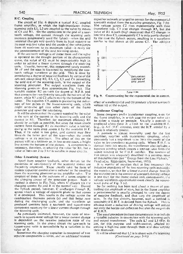
Fig. 5.- Voltage waveforms to produce a sawtooth current in (a) pure inductance, (b) resistance and (c) inductance
and resistance combined.
May, 1952
which makes it necessary for the voltage waveform to be of complicated form to drive a sawtooth current through them. In order to produce a sawtooth current through a pure inductance, a waveform as shown by Fig. 5 (a) is required. This is better seen when it is considered that a steady change of current through an inductance as represented by, say, the scanning stroke of a sawtooth waveform will produce a steady voltage across the inductance proportional to the rate at which the current changes.
On the other hand, if the scanning coils were mainly resistive the voltage waveform would have the same shape as the current waveform and so would be saw - toothed (Fig. 5 (b)). In practice, where both inductance and resistance are present. however, it is necessary to combine the waveforms of (a) and (b) in their correct proportions (Fig. 5 (c)), in order to get a sawtooth current waveform.
To achieve the desired waveform, really determined by the ratio of inductance to resistance, the scanning coils may be energised from a source Of high impedance. One method would be to connect the scanning coils in series with the anode of a pentode valve and, by the application of a sawtoothed voltage on its grid, a sawtoothed current will be driven through the coils. An alternative method is to drive the scanning amplifier valve with a voltage of waveform similar to that of Fig. 5 (c), when the same result would be achieved.
In order to obtain a correctly positioned raster, it is necessary for the scan- ning spot to be deflected equally on either side -and above and below the geo- metrical centre of the fluorescent screen. This is controlled not only by the correct matching of both pairs of scanning coils, but also by ensuring the deflect- ing currents have no D.C. component.
The latter condition is
PRACTICAL TELEVISION 539
achieved by coupling the scanning coils to the amplifier either by means of a transformer or an R.C. network, but in each case it is necessary to match the impedance of the roils to the type- of valve employed. When the coupling is a transformer,
Drive
Fig. 8. -A transformer coupled line output stage with variable linearity and width controls.
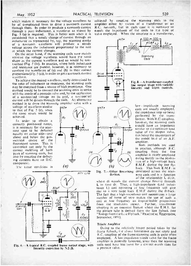
Fig. 6. -A typical R.C. coupled frame output stage, with linearity correction by N.F.B.
low - impedance scanning coils are usually employed, the impedance step -up being performed by the trans- former. With R.C. coupling. however, the scanning coils should have an impedance similar to the optimum load value of the output valve, this being the counterpart of the anode load of an A.F. amplifier.
Both methods are used in practice, although R.C. coupling from the line amplifier is rarely employed owing mainly to the genera- tion of a high -voltage back E.M.F. during the line fly- back. This back E.M.F. is
Fig. 7. -Other linearising developed across the scan - devices. ning coils and is a function
of the relationship L di!dt, where di equals the current change flowing through L in time dt. Thus, a high- impedance (and induc- tance L) coil operating at line frequency will give rise to a very large back E.M.F during the flyback. The fact that a high- impedance coil necessitates a large number of turns of wire makes the use of such a. coil at line frequency an impracticable proposition from the insulation aspect. Further, transformer coupling is an essential feature where the E.H.T. for the picture tube is derived from the line flyback (see "Energy from the Line Flyback," PRACTICAL TELEVISION, September, 1951).
Triode Amplifier Owing to the relatively longer period taken by the
frame flyback, the above limitations do not apply and R.C. coupling of the frame -scanning coils is quite often employed. A low- impedance triode valve for the frame amplifier is generally favoured, since then the scanning coils need have less turns for a correct match than for a pentode valve.
540 PRACTICAL
R.C. Coupling The circuit of Fig. 6 depicts a typical R.C. coupled
frame amplifier, in which the high -impedance frame - scanning coils LI, L2 are coupled to the valve by means of CI and R1. On-the application to the grid of a saw- tooth voltage, the current through the scanning coils increases progressively until the flyback -when the grid potential changes very quickly from its least negative to its most negative value and the anode of the valve jumps from itS minimum to its maximum value -is ready for the commencement of the next scanning stroke.
If the sawtooth voltage is of linear form and the valve is operated on the straight portion of its characteristic curve, the value of Cl must be impracticably high in order to achieve a linear current through the scanning coils. Usually, however, this component rarely exceeds 50 pF and the scan is linearised by modifying the saw- tooth voltage waveform at the grid. This is done by introducing a degree of negative feedback by virtue of the network comprising R2, R3, C2, C3 and C4 connecting the cold end of the scanning coils, to the output of the scanning generator. The output waveform from the scanning generator then approximates Fig. 5 (c). The variable resistor R2 controls the degree of N.F.B. and thus corrects for non -linearity towards the bottom of the raster, while R3 and C3 affects mainly the bottom of the raster. The capacitor C5 assists in preventing the induc- tion of line pulses in the frame -scanning coils, which might otherwise get into other parts of the frame generator and upset the interlacing.
It will be obvious that the current supplied by the valve is the sum of the current in the scanning coils and the current in R1. Therefore, for maximum efficiency R1 should be as high as possible, but since the mean anode current flows through R1 its maximum value is limited, owing to the volts drop across it by the available H.T. Thus, if its value is too great, grid current may flow towards the latter part of the scan -when the anode voltage is at its minimum. The effect of this on the picture will be a foldover or, in less severe cases, a bright line across the bottom of the picture. A compromise is necessary, therefore, in selecting the value for RI, but a value of between 2 to 3 k2 is suitable in most circuits.
Other Linearising Devices Apart from negative feedback, other devices for the
correction of non -linearity of the scanning stroke are frequently employed. These usually take the form of resistor capacitor combinations included in the coupling from the scanning generator to the amplifier valve. The simplest of these is the inclusion of a series resistor in the charging circuit of the generator proper. Such a method is shown in Fig. 7 (a), where C charges via the charging resistor Rc and R in the normal way. During the flyback period, however, C discharges through R, across which a voltage of opposite phase to that across C is developed. This results in the voltage across the combination (between points (a) and (b)) being zero during the discharging cycle, and the waveform so produced contains both a sawtooth and square -wave component necessary for a linear current change through the scanning coils.
As previously intimated, however, the ratio of saw- tooth to square -wave voltage for a linear current change is dependent on the resistive inductive ratio of the scanning coils. In the above circuit the sawtooth to square -wave ratio is controllable by a variation in the value of R.
Sometimes the charging capacitor is composed of two separate components in series, and an additional resistor
TELEVISION May, 1952
capacitor network arranged to correct for the exponential sawtooth output from the scanning generator, Fig. 7 (b). The voltage across C2 rises exponentially with time (waveform (a)), C3 also charges through Rl, but the value of RI is such (high resistance) that C2 charges in less time than C3, consequently C3 is only partly charged by the time the flyback occurs, resulting in a waveform similar to that shown at (b) across C3. The additi\e
Time --- Fig. 9.- Counteracting for the exponential rise in current.
effect of waveforms (a) and (b) produce a linear sawtooth voltage (c) at the output.
Transformer Coupling Some designers prefer transformer coupling, even for
the frame amplifier, in which case the output valve can be either a triode or pentode. Usually a pentode is employed where there is a limit to the available H.T. (e.g., in A.C.; D.C. circuits), since the H.T. needed by a triode is relatively greater.
A pentode is almost invariably used for the line amplifier, together with transformer coupling, which commonly has a step -down ratio from the anode of the valve to low- impedance scanning coils. Where E.H.T. is derived from this source, the transformer also includes a separate winding which creates a step -up ratio from the anode winding to the E.H.T. rectifier. The function of this circuit was adequately described in a previous issue of this publication (see " Energy from the Line Flyback," PRACTICAL TELEVISION, September, 1951).
It is worthy' of mention that at line frequency thee inductive impedance of the line- scanning coils outweighs the resistive, so that for a linear current change through the scanning coils the content of sawtooth driving voltage is less than for the frame circuit and, consequently, the voltage waveform approximates more closely the square - wave pulse of Fig. 5 (a).
So far nothing has been said about a means of con- trolling the amplitude of scan, but in the frame amplifier a potentiometer is usually arranged to vary the degree of negative feedback, and thus vary the amplitude of scan. In the line circuits, however, such a method is unsuitable if E.H.T. is derived from the flyback. This is obvious since a reduction of driving voltage will reduce not only the horizontal deflection but also the magnitude of E.H.T.
The usual procedure in these circumstances is to include a variable inductor in connection with the scanning coils and output transformer. The coils L2 and L3 (Fig. 8) are, for this purpose and width -control, affected by moving a high -mu core through them and thus varying their reactance.'
It will be observed that L2 is in shunt'with the scanning (Continued on page 544.) '
May, 1.952 PRACTICAL TELEVISION 541
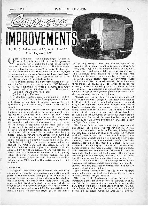
IMPROVEMENTS By D. C. Birkinshaw, M.B.E., M.A., A.M.I.E.E ,
Chief Engineer, BBC
ONE of the most striking facts about the present scientific age is the rapidity with which apparatus required for a particular branch of technology
can develop once it has made a start. This is no doubt due to the fact that such a wealth of scientific discovery has now been made in various fields that those engaged in developing a new piece of equipment have a vast array of established techniques in their own and in sister branches of science from which to draw.
The television camera is an excellent example of this state of affairs. In the pre -war years the BBC Television Service was employing two types of camera, both made by Electric and Musical Industries, Ltd. These were :
(1) The Standard Emitron ; and (2) The Super Emitron.
The Standard Emitron camera was used in the two studios," A " and " B," in the film equipment associated with these set -ups and in outside broadcasts. Its appearance by now will be very familiar to users of this journal.
It is not proposed to describe the operation of the Emitron tube in any detail in this article, since by now the action is doubtless well known. In brief, a lens mounted in the camera housing focuses the light image on to a photo- sensitive mosaic which emits electrons. The resulting deficiency of electrons at a given point on the mosaic is dependent on the brightness of the picture detail focused upon that point. The mosaic is then scanned by an electron beam which re- charges the 'elements of the mosaic in succession, the charging current naturally varying from element to element and constituting an electric current representing the brightness of the picture details point by point and line by line.
It is light in weight and simple in construction, but perhaps its most important characteristics are the excellent definition which it gives and which is still not surpassed by any of its successors, and the fact that it allows one to take considerable liberties with lighting values while still yielding a pleasant picture. So long as there is plenty of light, by which is meant an incident value of some 250ft. candles, the precise amount is not important.
Insensitivity As against these advantages, however, the camera is
comparatively insensitive by modern standards, and due partly to this insensitivity and partly to the fact that it requires long focus lenses, it is capable of only a shallow depth of focus. By this is meant that objects situated appreciably in front or behind the plane on which the focus is set are not clearly focused and appear blurred. Another matter which causes difficulty in practical studio operation is that the camera is subject to what are known
as " shading errors." This may best be explained by saying that if the camera is set up to face a uniformly lit scene, then it will yield an image which is unduly dark in one corner and unduly light in the opposite corner. This departure from faithful portrayal of the scene lighting can be largely counteracted by injecting into the electronic circuits certain recurrent waveforms whose amplitude must be controlled manually for each camera throughout the production. In order to focus the camera, the lens is moved by rack and pinion in front of the tube. A duplicate and ganged lens focuses an identical image on to a ground glass screen from which the camera operator judges his focus.
Nevertheless, it is only fair to the camera to state that due to the excellent design of the associated circuits by E.M.L. Ltd., and the practised operating technique of the BBC engineers, these disadvantages have been so largely mastered that the camera, which is still used today, yields excellent pictures. At the time of writing this article the camera is used, as it always has been, for Drama, many Documentary and other smaller studio programmes ; but as will be seen, has been superseded on O.B.s, the Children's Programme, and very largely on Light Entertainment.
The Super Emitron camera was really experimental throughout the whole of the pre -war period. It was based on a new tube, the Super Emitron, differing from the Standard Emitron in that it possessed an " image section " between the lens and the mosaic target. The light from the lens fell upon a photo cathode which was a uniformly conducting photo emissive surface, and the electrons leaving it bombarded a mosaic which was scanned in the same way as the Emitron. This electronic bombardment of the mosaic caused secondary emission which released electrons much as if the mosaic had been bombarded by the original light image. This emission was comparatively stronger, however, with the result _
that the new camera had about five times the sensitivity of the Standard Emitron. Its use made possible outside broadcasts of external sports events occurring in rather gloomy weather, and indoor events with a moderate amount of additional lighting.
The focusing arrangements for the Super Emitron composed a ganged optical viewfinder on the same lines as that provided for the Emitron.
There was little development during the war, but immediately the Television Service was resumed in 1946,' the British television equipment manufacturers and the BBC Engineering Division got together to try to work out a design for an improved camera into which should be built all the features which the three years of pre -war
542 PRACTICAL
experience had shown to be desirable. It is surprising what a very considerable number of points have to be watched carefully in the design of a television camera which is to be efficient and pleasant to use. The following are among the most important :
(1) The camera should be as light as possible. (2) It must be balanced. (3) It should have high sensitivity. (4) The depth of focus should be considerable. (5) It should have a choice of angles of view. (6) It should possess an efficient focusing viewfinder. (7) It should be built in the form of a number of
separately detachable sub -sections. (8) It should have a remotely operated iris control.
Let us consider in turn these various points and examine the progress which has been made.
Weight A heavy camera is not only difficult to handle on any
type of programme, but is very, inconvenient in outside broadcasts. When the rig is being set up the camera may have to be manoeuvred up winding stairs and ladders to high vantage points. It has to be admitted with regret that in this respect there has been no progress whatever in the post -war period. Instead, cameras have grown heavier. This is very largely the inevitable result of endeavouring to build into these cameras the maximum number of useful operational features, each one unfortunately contributing its own modicum of weight to the total. It is rarely that a camera weighs less than 100 lb. and a reduction in this figure still remains the aim of the camera designer.
Balance A camera whose weight is unbalanced and which is
inadvertently released by its operator might fall forward and suffer severe damage. There is a- tendency for this to happen, because the aggregate weight of the lenses in the turret is considerable and this tends to pull the camera forward. However, much can be done by siting the supporting point forward of the centre of the base, and in addition a cable entry at the rear will tend to restore balance by pulling the camera down at the rear end.
Sensitivity This -is a most important character-
istic, because not only are lighting costs reduced, but it becomes possible to take the camera to public functions without the need for television to ob- trude itself by importing a great quantity of supplementary lighting. It is perhaps in the field of sensitivity that the major post -war advance has been made. The Photicon camera tube, designed by Pye, Ltd., the Cathode Potential Stabilised Emitron, designed by Electric and Musical Industries, Ltd., and the Image Orthi- con, fitted by Pye, Ltd., and the Marconi Wireless Telegraph Co., Ltd., are all much more sensitive than the pre -war Standard Emitron. The Photi- con tube of Messrs. Pye, Ltd., belongs to the miniature image iconoscope class of camera tube and may be con- sidered to be a modern development from the unminiaturised , image icono- scope class to Which the E.M.I. Super
TELEVISION --May, 1952
Emitron belongs. The Photicon tubes are incorporated in the Pye cameras at present used in studio " G " at Lime Grove, from which a great number of Light Enter- tainment productions are televised. It is a feature of this type of . tube that the increased sensitivity is wholly employed in conferring upon the reproduced image an enhanced depth of focus, thus while the lighting intensity in studio " G " is much the same as that in the older studios " A " and " B " at Alexandra Palace, the pictures are better due to improved depth of focus. The Cathode Potential Stabilised or C.P.S. Emitron of Messrs. E. M.I. is fitted in the cameras in studies " D " and " H " at Lime Grove and is in fact even more sensitive than the Photicon, since not only is there greater depth of focus, but there is an economy in lighting values. At present the C.P.S. Emitron is largely employed in Children's Hour productions.
The greatest advance in sensitivity, however, has been reached by the Image Orthicon tube, initially developed in America, but now available in this country, and it is now used almost exclusively for outside broadcasts. It requires a lighting intensity of but 25ft. candles. while at the same time possessing an immense depth of focus. On a bright, sunny day this type of tube is so sensitive that not only have extremely small apertures of ¡64 to be used, but in addition one or two neutral filters have to be interposed in the light path as it is impossible to get sufficient suppression of the light by the use of the smallest aperture stop alone.
Obviously, the maximum advantage of such a camera is not reaped in these conditions, but at indoor public functions, such as ceremonial dinners or at a football match in the latter part of a foggy winter afternoon, this type of tube is in its element.
Depth of Focus If the depth of focus is poor, then much of the advan-
tage of high definition is lost because such definition is only present in the image of objects situated at the particular distance from the camera at which it is focused. Not only does the picture produced by a camera without deep depth of focus lack clarity, but the
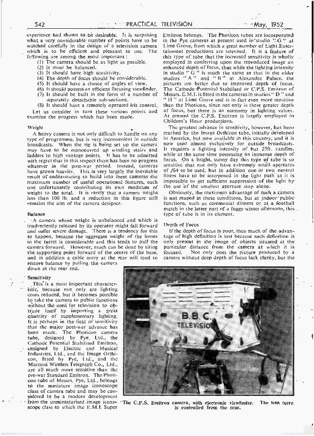
' The C.P.S. Emitron camera, with electronic viewfinder. The leas turre is controlled from the rear.
May, 1952 PRACTICAL TELEVISION 543
work of the camera operator is rendered much more arduous because he must obviously have a great deal more focusing to do as the centre of interest moves to and from the camera. The property of great depth of focus is an almost automatic attribute of a sensitive camera. For this reason there has been substantial improve- ment in recent times as the following figures will illus- trate.
Using a standard Emitron, the depth of focus when the
while the use of a narrow taking angle, such as 6 dee. or 4 deg., enables the camera to take, in effect, a close up of an object in a scene while yet being a considerable distance away from it. This property is of immense value in an O.B., where it is often physically impossible for a camera- to be placed close to an object of interest. A particular example of this is a cricket match. Here the camera must be sited outside the boundaries of the field, but should be equipped to give a close -up of a bats-
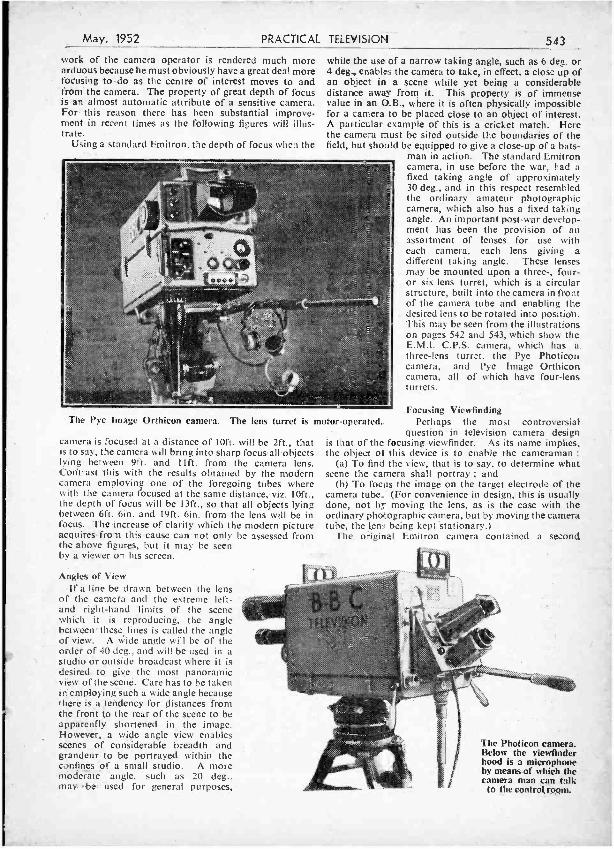
man in action. The standard Emitron camera, in use before the war, had a fixed taking angle of approximately 30 deg., and in this respect resembled the ordinary amateur photographic camera, which also has a fixed taking angle. An important post -war develop- ment has been the provision of an assortment of lenses for use with each camera, each lens giving a different taking angle. These lenses may be mounted upon a three -, four - or six -lens turret, which is a circular structure, built into the camera in front of the camera tube and enabling the desired lens to be rotated into position. This may be seen from the illustrations on pages 542 and 543, which show the E.M.I. C.P.S. camera, which has a three -lens turret, the Pye Photicon camera, and Pye Image Orthicon camera, all of which have four -lens turrets.
The Pye Image Orthicon camera. The lens turret is motor -operated.
camera is focused at a distance of loft. will be 2ft., that is to say, the camera will bring into sharp focus all objects lying between 9ft. and 11ft. from the camera lens. Contrast this with the results obtained by the modern camera employing one of the foregoing tubes where with the camera focused at the same distance, viz. loft., the depth of focus will he 13ft., so that all objects lying between 6ft. 6in. and 19ft. 6in. from the lens will be in focus. The increase of clarity which the modern picture acquires from this cause can not only be assessed from the above figures, but it may be seen by a viewer on his screen.
Angles of View if a line be drawn between the lens
of the camera and the extreme left - and right -hand limits of the scene which it is reproducing, the angle between these lines is called the angle of view. A wide angle will be of the order of 40 deg., and will be used in a studio or outside broadcast where it is desired to give the most panoramic view of the scene. Care has to be taken in employing such a wide angle because there is a tendency for distances from the front to the rear of the scene to be apparently shortened in the image. However, a vide angle view enables scenes of considerable breadth and grandeur to be portrayed within the confines of á small studio. A more moderate -angle, such as 20 deg., may ' be used for general purposes,
Focusing Viewfinding Perhaps the most controversial
question in television camera design is that of the focusing viewfinder. As its name implies, the object of this device is to enable the cameraman :
(a) To find the view, that is to say, to determine what scene the camera shall portray ; and
(b) To focus the image on the target electrode of the camera tube. (For convenience in design, this is usually done, not by moving the lens, as is the case with the ordinary photographic camera, but by moving the camera tube, the lens being kept 'stationary.)
The original Emitron camera contained a second
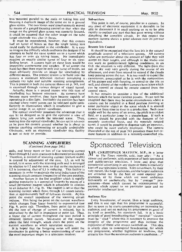
The Photicon camera. Below the viewfinder hood is a microphone by means of which the camera man can talk
to the control room.
544 PRACTICAL TELEVISION May, 1952
lens mounted parallel to the main or taking lens and focusing a duplicate image of the scene on to a ground glass screen. The two lenses were simultaneously moved by means of a ganged focusing control so that when the image on the ground glass screen was correctly focused, it could be assumed that the other image on the tube target electrode was also in focus.
It must be remembered, however, that this camera had no turret of lenses so that the single taking lens could easily be duplicated in the viewfinder. It is easy to imagine the difficulty which confronts the designer if he attempts to build the same system on to a turret which has four or even six taking lenses. He immediately requires an exactly similar turret of four or six view - finding lenses. A camera built on these lines would be impossibly cumbersome and weighty. If we accept the hard fact that there must be only one turret of lenses, we must. obviously provide an image for viewfinding by different means. The present system is to build into the camera a miniature television receiver containing .a
cathode ray tube and suitable scanning arrangements. This is present in both the cameras shown on p. 543, and is examined through various designs of visual tunnel.
Actually, there is a second reason why this type of viewfinding has become necessary. As cameras have become more sensitive, they have become capable of operating in a dim light. Inevitably the position has been reached where many scenes can be televised quite satis- factorily in illumination which is insufficient to give a useful image in an optical viewfinder.
The optical viewfinder possesses the advantage that it can be so designed as to give the operator a view of objects lying just outside the televised scene. Thus, looking into the optical viewfinder, he can see in advance as he pans his camera around whether he is about to televise anything uninteresting or actually undesirable Obviously, with an electronic viewfinder this facility is not so easy to provide.
Sub -sections This point is not, of course, peculiar to a camera. In
any piece of electronic equipment it is desirable to be able to disconnect it in small sections so as to be able rapidly to replace any part that has gone wrong without disturbing the complete circuit. In this respect the modern camera shows a great advance over its pre -war equivalent.
Remote Iris Control It should be recognised that the lens iris is the natural
amplitude control of a television system. All camera tubes are particular about the amount of light they will accept on their targets, and although in the studio one can work. to predetermined lighting conditions, in an O.B. the situation is very different. The light from the sun or sky may vary greatly during the course of an afternoon, and even from second to second if the clouds keep passing across the sun. It is too much to expect the cameraman, preoccupied as he is with the composition of his picture and with focusing, to attend to the iris as well, and almost all the modern cameras have irises which can be opened or closed by remote control from the control room.
It but remains to consider a few of the additional features which the latest cameras possess. It can well be imagined that there may be some circumstances where a camera can be installed in a fixed position pointing at some particular object in the scene which it is desired to televise from time to time in a production. Such case might well be the scene of an arena, the pitch in a cricket field, or a particular jump in a steeplechase. If such a camera should be provided with the features of (a) remotely controlled focus, and lb) remotely rotated turret, it would be possible to dispense with an operator, who could be more usefully employed. The camera illustrated at the top of page 543 possesses these two re- mote features in addition to a remotely -controlled iris.
SCANNING AMPLIFIERS (Continued from page 540.)
coils, and hence more or less of fie scanning current flows through L2 as its reactance is decreased or increased. Therefore, a control of scanning current (picture -width) is created by adjustment of the core. L3, as will be noted, is in series with the scanning coils and is arranged in relation to L2 and the core, so that as the reactance of L2 is increasing, that of L3 is reducing. This facility is necessary in order to maintain the total inductance of the scanning circuit constant irrespective of the core position.
Another feature in the line amplifier which is rapidly gaining popularity is a control of linearity by means of a
small permanent magnet which is adjustable in relation to an inductor (LI, Fig. 8). The magnet is set so that the scanning current which flows through LI causes satura- tion at approximately half of full -scan current. At this point the overall impedance of the scanning circuit reduces. This being the point on the current waveform which changes from linear (nearly) to exponential (see Fig. 9, point (a)). Therefore, from point (a) to point (b) the rate of change of current is reduced, but is neutralised by the fall in impedance at point (a). Thus, a linear rise of current throughout the scan period is obtained, (dotted curve). Movement of the magnet alters the field strength, which alters the point on the current waveform at which saturation occurs.
It is hoped that the foregoing notes will assist the Constructor in gaining a better understanding of one of the most important stages in a television receiver:
Sponsored Television MR.
CHRISTOPHER MAYHEW, M.P., in a letter to The Times recently, said, inter alla : " As a
viewer and performer, with experience of both sponsored and public- service television, I hope and pray that commercial advertising in any shape or form is resolutely kept off our television screens. Keen advertisers, by their very nature, like large audiences, and the largest audiences are attracted not by the best or most enjoyed pro- grammes, or by those which are most ambitious technically or aesthetically, but by " average " pro- grammes -those which cannot be misinterpreted by anyone, which appeal to no particular taste and no particular intellectual level.
Audience Size Every broadcaster, of course, likes a large audience,
and this is one sign that his programme is successful. But as soon as he starts concentrating on increasing his audience, and not on making his programme as good of its kind as possible, his standards fall. It is a basic principle of good broadcasting that " marginal " viewers must be " shed " where this is necessary to improve the integrity of the programme and thus increase the enjoyment of those who remain switched on. This idea is utterly alien to commercial broadcasting, for which any programme, whether highbrow or lowbrow, that attracts less than the maximum audience is anathema, .."
May, 1952 PRACTICAL TELEVISION 545
Pioneers o Television 3. -DR. FERDINAND BRAUN, AND THE CREATION OF THE CATHODE -RAY TUBE
KARL FERDINAND BRAUN, electrical physicist of Strasbourg University, and Director of the once -famed Physical Institute of that city. How
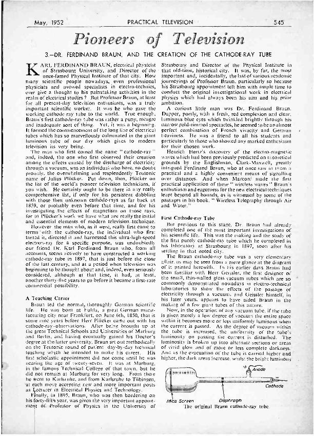
many scientific people nowadays, even professional physicists and avowed specialists in electro- technics, ever give a thought to his painstaking activities in the realm of electrical studies ? But Professor Braun, at least for all present -day television enthusiasts, was a truly important scientific worker. It was he who gave the working cathode -ray tube to the world. True enough, Braun's first cathode -ray tube was rather a puny, meagre and inadequate sort of thing. Yet, it was a beginning. It formed the commencement of the long line of electrical tubes which has so marvellously culminated in the giant luminous tube of our day which gives to modern television its very being.
The man who first coined the name " cathode -ray " and, indeed, the one who first observed their creation among the effects caused by the discharge of electricity through a vacuum, was an individual who bore, no doubt proudly, the. overwhelming and resplendently Teutonic name of Julius Plücker. Put down, then, Plücker on the list of the world's pioneer television technicians, if you wish. He certainly ought to be there in any really comprehensive list, if only for his persistent dabbling with those then unknown cathode -rays as far back as 1859, or probably even before that time, and for his investigating the effects of magnetism on those rays, for in Plücker's work we have what are really the initial and essential elements of modern television. technique.
However the man who, as it were, really first came to terms with the cathode -ray, the individual who first tamed it, directed it and harnessed this ultra -high -speed electron -ray for a specific purpose, was undoubtedly our friend Dr. Karl Ferdinand Braun who, from all accounts, seems actively to" have constructed a working cathode -ray tube in 1897, that is just before the close of the last century, and at a period when television was beginning to be thought about and, indeed, even seriously considered, although at that time, it had, at least, another thirty -five years to go before it became a first -rate commercial possibility.
A Teaching Career Braun led the normal, thoroughly German scientific
life. He was born at Fulda, a great German manu- facturing city near Frankfurt, on June 6th, 1850, that is some nine years before Herr Plücker came out with his cathode- ray- observations. After being brought up at the great Technical Schools and Universities of Marburg and Berlin, and having eventually gained his Doctor's degree at the latter university, Braun set out methodically on the Teutonic round of patient day -by -day technical teaching which he intended to make his career. His first scholastic appointment did not come until he was nearing the age of twenty- seven. It was at Marburg, in the famous Technical College of that town. but he did not remain at Marburg for very long. From there he went to Karlsruhe, and from Karlsruhe to Tübingen. at each move accepting new and more important posts as Lecturer in Electrical Physics and Technology.
Finally. in 1895, Braun, who was then bordering on his forty-fifth year, was given the very important appoint - merit of Professor of Physics in the University of
Strasbourg and Director of the Physical Institute in that old -time, historical city. It was, by far, the most important and, incidentally, the last of various academic journeyings of Professor Braun, particularly so because his Strasbourg appointment left him with ample time to conduct the original investigational work in electrical physics which had always been his aim and his prior ambition.
A curious little man was Dr. Ferdinand Braun. Dapper, portly, with a fresh, red complexion and clear. luminous blue eyes which twinkled brightly through his narrow gold- rimmed spectacles, he seemed to be an almost perfect combination of French vivacity and German heaviness. He was a friend to all his students and particularly to those who showed any marked enthusiasm for their chosen work.
Henrich Hertz's discovery of the electro- magnetic waves which had been previously predicted on theoretical grounds by the Englishman, Clark -Maxwell, greatly intrigued Ferdinand Braun, who at once saw in them a practical and a highly convenient means of signalling over distances. And when Marconi made the first practical application of these " wireless waves " Braun's enthusiasm and eagerness for the new electrical techniques leapt beyond all bounds, as is witnessed by some of the passages in his book, " Wireless Telegraphy through Air and Water."
First Cathode -ray Tube But previous to this stage, Dr. Braun had already
completed one of the most important investigations of his scientific life. This was the making and the study of the first purely cathode -ray tube which he completed in his laboratory at Strasbourg in 1897, soon after his settling in that noted city.
The Braun cathode -ray tube was a very elementary affair, as may be seen from a mere glance at the diagram of it printed herewith. In his earlier days Braun had been familiar with Herr Geissler, the first designer of the small, thin -walled glass vacuum tubes which are so commonly demonstrated nowadays in electro- technical laboratories to show the effects of the passage of electricity through a vacuum, and Geissler himself, in his later years, appears to have aided Braun in the making of a few giant tubes of this nature.
Now, in the operation of any vacuum tube, if the tube is given merely a low degree of vacuum the entire space within it becomes more or less uniformly luminous when the current is passed. As the degree of vacuum within the tube is increased, the uniformity of the tube's luminosity on passing the current is disturbed. The luminosity is broken up into alternate sections or areas of vivid glow and of more or less complete darkness. And as the evacuation of the tube is carried higher and higher, the dark areas increase, whilst the bright tuminóus
Mica Screen Diaphragm The orginat Braun cathode-ray tube.
4
546 PRACTICAL
areas within the tube become progressively smaller and smaller until, at very high degrees of vacuum, the last bright area disappears behind the anode plate or electrode of the tube. At extremely high degrees of vacuum, the interior of the tube is almost completely non -luminous, but, at this stage, as Braun himself demonstrated, a new type of ray was being shot off from the cathode surface. This was the " cathode -ray " of which the erstwhile Herr Julius Plücker had spoken of in 1859, and other experimenters had mentioned, but it was given to Ferdinand Braun in his Strasbourg experiments to show that these rays could be made visible at their point of impact with a luminous screen coated with a glow - producing substance, such as one or the platinocyanides of calcium, barium or magnesium, which luminesced brilliantly under the influence of the rays.
Diverting the Rays Having rendered visible the point of impact of cathode -
ray and screen, Braun's next move was to divert the rays out of their essentially straight -line path of travel from the cathode of the tube by the external application of a permanent magnet or of an electro- magnetic field. This, of course, was a direct application of Plücker's former discovery.
In Braun's first cathode -ray tube the stream of rays was narrowed down and formed into a thin pencil by being made to pass through a small metal diaphragm before, ultimately, impinging on a mica plate coated with luminescing material on which it set up a bright spot which could be moved about to any area or point of the screen by magnetic or electro- magnetic control of the ray -pencil as it travelled along the tube.
Braun seems to have been aware that his cathode -rays were actually nothing other than streams of high -speed electrons shot off from the negative electrode or cathode of the tube, but it never occurred to him that the rudi- mentary electron -ray tube of his would ultimately prove to be the key which would give the entry to the realms of television, for, to Braun, the ultimate possibility of television was a subject which, at that time, was hardly worth a moment's thought.
The Oscillograph Professor Braun, even if he had been working actively
on television possibilities, had hardly a chance to carry out such work with an untramelled mind, for, at this period, wireless communication suddenly arose and seized with vivid intensity the imaginations of all scientific men. He made a few modifications and improvements on the design of his original cathode -ray tube, but it was not until some years after its first construction that, in 1902, he showed how its moving ray -spot could serve to trace out on the screen the various forms of alternating - current waves. Thus, for the first time, the cathode -ray tube, in one of its earliest guises, was converted in a most useful electrical implement -the cathode -ray oscillograph.
Perhaps strangely, when we consider Braun's fund of inborn inventive energy, this investigator never proceeded beyond this stage with his electrical tubes. The interests and intense fascinations of the then rapidly developing wireless telegraphy completely overcame him. He had become, as we might nowadays express it, a fervid wireless experimenter. As early as 1899, he obtained a radio patent for a new tuning system, and he devised the " Braun wireless transmitter " which was subsequently manufactured by Siemens and Halse, of Berlin. It was a spark transmitter working in conjunction with the then standard type of receiving set in which use was made of coherer detection. With this equipment, Braun.
TELEVISION May, 1952
in 1899, established wireless communication by telegraphy between Heligoland and Cuxhaven, employing a trans- mitting aerial some 90 ft. high.
Braun Shares the Nobel Prize Soon after his creation of the first cathode -ray oscillo-
graph, Dr. Braun joined a small band of other wireless pioneers (von Arco, Slaby and Siemens) to form what became known as the " Telefunken " organisation. Braun devised a method of directional wireless, and among all his activities of this period of his career he found time to share with the oncoming Marconi the famous Nobel Prize for work in wireless communication.
The rest of Braun's life was taken up partly with academic activities and partly with his Telefunken interests. Curiously enough, this ever -active individual, who created for television science the cathode -ray device which was to become the very foundation of its practical success in our days, never made another investi- gation into the possibilities of a working television system.
At the beginning of 1914 Braun essayed to travel to New York for the express purpose of acting as an expert witness in a difficult matter of litigation which had then involved the Marconi Company. He lingered long in America, and before he could return to Europe, America had entered into the war against the German Powers. So that Ferdinand Braun, who went to the United States as an interested visitor, found- himself compelled to remain there on the status of an internee. He tried to make the best of what was for him a thoroughly bad job.
Whether such an unexpected restriction of freedom directly took toll of his health we do not know for certain. But there remains the fact that within a short time the Professor began to fall ill. His condition became worse. A stranger in the land, and, worse still, an enemy national, he was removed to a hospital in Brooklyn. There he lingered for some time. On the morning of 14th August, 1918 his end came. And so, too, less than three months afterwards, came the end of Germany's First World War. Professor Braun had been little interested in the conflict. Indeed, he seems to have deplored it, but he had been caught up in the mill and it had broken him.
Club Report NORTHAMPTON AREA TELEVIEWERS' SOCIETY Secretary : G. T. Wilson, 95, Ennerdale Road,
Northampton. AT the Society's March Meeting the speaker was
Mr. Cyril Page, who told of his experiences in Korea while filming for the BBC Newsreel.
A very pleasant evening was spent at Croydon, where a party from the Society attended the British Television Viewers' Society's Annual Dinner and Dance. Many BBC personalities were present.
Mr. Eric Robinson, BBC Musical Director, has agreed to become President of the Society.
The Annual Meeting will be held at The Wedgewood Chambers, Abingdon Street, Northampton, on Thursday, April 17th.
A party will be travelling to the Letchworth Society's Annual Dinner and Dance on April 24th. A group attended this function last year. Mr. G. T. Wilson (secretary), Mr. R. North and Mr. Flude hope to make a party up of 24 members for this function.
Members will be visiting the BBC shortwave transmitter at Daventry in May.
Membership now is 285.
$1
1
-May, 1952 PRACTICAL TELEVISION 547
Televisi®n at 200 miles NEW MODEL SC23 TV PRE -AMPS. ALL CHANNELS
High gain and low noise. Customs built to the highest standards. Ample bandwidth for good definition. .
Ideal for the " difficult " fringe and ultra fringe areas. Each pre -amp. supplied guaranteed to have been "air tested" and to have received both vision and sound at 200 miles using a standard commercial superhet. receiver. Models SC22 and SC23 have self -contained metal rectifier power supply, 2001250v. A.C. 12 months' guarantee. Immediate delivery.
RETAIL PRICE LIST (Trade enquiries invited)
SC23, new model, ES. S. 0. SC22, two -stage, E8. 10.0.
SC2I, two -stage, E6. 6. 0., requires power supply.
SG12, TV Sig. Gen., E6. 19.6. PGI I, Pact. Gen., [14.0.0.
TELEVISION SIGNAL GENERATOR Frequency range 40/70 M cs. Calibration chart for all Television Channels. Modulation on sound and vision optional. Sensitive meter fitted for use as grid dip oscillator. Ideal for service engineer and experimenter. Measures coil, aerial frequencies, .etc. The only one of its kind on the market. Self- contained power supply, 2001250v. A.C. 12 months' guarantee. Immediate delivery.
J. V. RADIO CO. 25, WILLIAM STREET (City Centre), PLYMOUTH. Manufacturers of Television Equipment Tel. 4737.
ALPHA OFFERS 1 WATT RESISTORS at 6d. each.
OZ4 81- IT'1 9;- 145 9,- 1.91 9!- 143 9,- 1CJGT 8.6 ".t:: 7/9 215SG 4/-
08 ::44 9;- 31,6 8/6 384 106 42 96 5C"4G 9/- 3C2G 9,8 5V3G'r 9/6 3Z451. 9'6 1240, 10:8 64C7 7 9 ORO 79 GMT 7'6 6C6 71 6D6 7'6 6F6M 9/- IiF6G 91- 0C:6G 7/6 6146 4/6 6J5GT 5/8 637M 8/8 6J7(4 7/9 PEN2I 8/8 HIN_3UD 81 6E71: 6/6 6K7G1' 86
VALV AI: Guaranteed.
Ma;or,ty in Maker's
6K80 12:8 61,6(4 116 6N7GT 7ß 6Q7G 11'6 68 47(11 11 6 68(17 7.9 68H7 G937 91 62IC7 7- 68N70T 116 68Q7 9 6 61370 9 - 6V6GT 9.6 6V60 9 6 6S5CT 64M6 11 6 04L5 9.- 77 7-9 788 96 7s 9,- 80 0,6 854 2:9 953 5- 930 3 3 9D2 49 1246 12H6 7/3 12K8 916 128117 7'8 T1.23 8,'8 VN23 8/6 12807 7/3 l'?BK7 8/- 1622 1116
ES
Cartons. 1934 BARRET-
TER 4/- AC6/PEN 7/9 C1'6 2i- C1'9 41- Dl)13 89 ECL60 12/6 ERCII 11/8 ISL41 11/6 Et'31 15/- 151148 2/- FK4/500 91 (16Z3 4/0 HL13C 9/- H63 2/6 11l"210 8,'- KT1161 8/9 KT66 1116 KT263 7/9 KT:43C 11/8 KTZ41 8/9 K'r30 11/- L1.220 6/9 ML4 8/9 ML6 41- M8/PEN 6/9 MH41 7/9 4D1 4/9 81)2 4/9 VP41 9,'- DI173M 91 11124 7'6 Faro_ ,,-
81.220 7/6 TH233 9/- TP22 12'- EF39 7/6 EB::4 3/- EF36 7/6 EK32 716 SP61 4 SF41 4,- EF'30 0'8 EF50 SYL.
CASLA 8/6 EA50 2!8 Y97Y 4/- DDIA 4/6 EFS 7/6 VR137 519 VP133 9i- RL32 7/9 VUlI] 4I8 VC120A 4: UV41 10/6 C'('1142 12,6 C1.41 11,1 V63 9!- H21 9/- E1436 819 7473 319 KT81 10/- 7174 9¡- 7117 9/- 703 706 9/- 6K8M 1208
I n kQ. 47 kQ, 30 kí1 150Q, 33 kQ, kit. 6 kQ, 25652, 39 1:12, 560 k fl,
4 7 kQ. 600 1,Q, 1 me¢Q. 330 kQ, 40 I, Q. 10 kQ. I kQ, 5.6 kQ, S4í0 k), '3300., 5SQ,80kQ,8kQ. RNTERVALVE TRANSFORMERS Type 1E114. 3 -t ratio, 2/9 each. A.IV.F.. Q.P.Y. type, 3,'11 each.
VIBRATORS. Ete., Oak, 6 t., 4 pin, U.X., 8/S each. Mallory. 6 y., 4 pin, C.X., 6,/6 each. Mallory Vibrator Unit. 12 r., output 134 r. II.C., 60 5w., 221 each.
PARMEXCO VIBRATOR TRANS- FORMER
12 v. to 160 v. A.C., 1116 each. Choke to match above TX, 160Q D.C., 13 h.; 50 ma., 5f- each.
TRIMMERS PhiJps 3,30 pF. and 3 /10 pF., concentric typea, 10d. each Pre -set, 2/13 1,F., 6d. each.
SPECIAL OFFER Vntume Control Morgnn'te. 1 mea. e-ith 14.'2.8. short spindle, Si- each. PF SILVER MICA CONDENSERS
50 pF., 200 pF., 360 pF., 180 pp.. 1100 pF. All 4d. each. Many other sizes available, METAL RECTIFIERS B.idge type. 12 v. 5 amp., 18/6. 12 r. I snip., 11- each. 3G v. 45 ma., 1'- each.
9 wave. 700 v. 45 ma:, 5/9 each. B.T.C., 12 v. 300 ma., 3'6 each.
MOULDED MICA CONDENSERS .01, 101, .002, 003, .003, .0001, .0002, .0003. .0003, .00002, .00005. All 5,'8 doz. BAKELITE CASE CONDENSERS 25 mid. 600 v., .02 mtd. 5 kV., 101 mm.
4 kV., .01 mid. 4 kV. All 1/- each.. PANEL MOUNTING PRESS SWITCH 2 -hole tiling type, 1/3 each_
WIRE -WOUND VOLUME CONTROLS 5Q. 200.0, 1 k), 5 kQ, 13 kQ 20 60, 25 kf), 33 kQ, 50 kQ, 219 each.
SPEAKERS 31" lilac, 3Q, 13/8; 5' Goodman, 2f), 11/6 ; 'u- Plessey, 30, 12,/6 ; 8' Plessey. 3Q, 148; 12' Truroz. 57/6; 10' flood- man, 328; 10' Ilota, 32/8; 5' Goodmue.
STANDARD CAN CONDENSERS 10 mfd. 500 y., 3/9 ; N mid. 430 e,, 1/11 ;
24 mfd. 430 r., 4/8 ; 8 z S mfd. 430 v., 4/- ;
10 a 8 mid. 450 v., 4'6; 32 s 12 mfd. 430 y., 7/ WIRE -END TUBULAR CONDENSERS
Hunts Tom Thumb, b mid. 430 v., 2,11 each. Dubiller, 9 mfd. 500 y.. S!- each. Dubilier, 16 mid 500 r., 4/S each.
WESTECTORS \5'1, t1 2, N3, WO, 11X6, 1112, II- cock TINNED COPPER WIRE I lb. reels, 24 8.N'.G., 1/6 each.
NEONS
Type 0071, 1,- each.
CO -AXIAL PLUGS AND SOCKETS
Pye type for i" or I" cable, 7i- doz. BULLDOG CLIPS
.Instrument type, 41- doz. Battery charger type. 7/- dos.
TERMS: Cash with order or C.O.D. Full list available- Send 3d. in stamps. Postage: 6d. under 10 / -, I/- under 20/ -, I/6 under SO -.
ALPHA RADIO SUPPLY CO. 5/6 VINCES CHAMBERS, VICTORIA SQUARE, LEEDS, I.
548 PRACTICAL TELEVISION May, 1952
T/V TECHNOLOGY
'Cs Home Study will give you a fuller understanding of Television problems
To the enthusiast for whom television is an absorb- ing interest and who wishes to understard more about it, or to those who are constructing their own sets and want complete knowledge of the theory underlying the constructional details, ICS offer a sound, practical and comprehensive course of instruction. It has given a high level of efficiency to many, who studied in their own time. What about you ?
FOR THE ENTHUSIAST OR INTENDING T/V ENGINEER
Course 'A' provides a sound introduction to radio and television principles, deals with the principles of reception and transmission, and includes the pre- liminary study of Mathematics, Electrotechnics and Radio and Television. Course ' B' offers a more comprehensive treatment of receiving equipment, deals in detail with modern principles of transmission and reception, and contains the necessary introductory instruction in mathematics, electrotechnology and radio.
The ICS also offer the following Courses in Radio :
Complete Radio Engineering Radio Service Engineers Radio Service and Sales
Advanced Short-Wave Radio Elementary Electronics, Radar and Radio
And the following Radio Examinations :
British Institution of Radio Engineers P.M.G. Certificates for Wireless Operators
City and Guilds Telecommunications C. and G. Radio Servicing Certificate (R.T.E.B.)
or FREE BOOKLET and full details of these highly successful courses, fill in and post the coupon below. Fees are moderate
and include ALL books required.
Generous Discount to H.M. Forces. (Dept. 172A, I.C.S. 75, Kingsway, W.C.2.)
CUT HERE INTERNATIONAL
CORRESPONDENCE SCHOOLS LTD. (Dept. 5725),
1.1 International Buildings, Kingsway, London, W.C.2.
1,. Please send booklet on subject
Name I (BLOCK LETTERS PLEASE)
I' Address
Age
.
ARTHURS HAVE IT! LARGE VALVE STOCKS TEST METERS IN STOCK
"AVO," "TAYLOR" TEST METERS SIGNAL GENERATORS
AND Leak Point One Amplifiers ... ,,. ... E28 7 0 Leak Pre -amplifiers 9 9 0 Leak Tuning Unit 36 17 4 Chapman Tuning Units ... ... .,, 17 6 8 Crystal and Moving Coil Microphones. Decca Replacement Heads and Pickups. Goodman's Axiom 150 Speakers ... 10 5 6 Partridge Output Transformers for Williamson Amplifiers ... ... ,.. 6 12 0 Cossor Double Beam Oscilloscope{ 1049 ... 132 10 o
LATEST VALVE MANUALS MULLARD, OSRAM & BRIMAR No. 4, 5/- each. MAZDA 2/- each. Postage 6d. extra. TELEVISION SETS, WIRE AND TAPE RECORDERS
ALWAYS IN STOCK, Goods offered subject to price alterations and being
unsold.
PROPS.' ARTHUR GRAY, LTD. OUR ONLY ADDRESS : Cray Rouse,
' 150 -152 Charing Cross Road, London, W.C.2 TEMp'e Bar 583314 and 4765 WRITE FOR LISTS
TELEGRAMS -" TELEGRAY, WESTCENT, LONDON." CABLES -" TELEGRAY, LONDON."
CLYDESIP_l L,E Bargains in Ex- Services Radio and Electronic Equipment
FOR INEXPENSIVE TELEVISION For the Low Cost "PIRACTICAL TELEVISION" Receive -. INDICATOR UNIT TYPE 82. LN MAKER'S ORIGINAL CASE
CLYDE DALE'S 35.9.6 CARRIAGE PAID
E.ILT. TRANSFORMER ` Primary tapped 230 -250 v. A.C. Sec_ (1) 3,000 v. 3 mA. tassel 2,500 v. Sec. (2) 4 y. 1 a. Sec. (3) 4 v. 1 a; tapped 2.5 v. Price, Pont Paid. 45' -. MAINS TRANSFORMER Primary tapped 230 -250 v. A.C. Sec. (1) 350-0-050 v. 160 mA. Sec. (ë.) 6.3 v. 3 a. Sec. (3) 6.3 v. 6 a. Sec; (4) 5 v. 3 a. Price, Post Paid, 55: .
Also available : potentiometers resistori, condensers, etc.
NEW LIST OF EX- SERVICE ITEMS No. 86. Now ready. Priced 1)8. Price credited on'purchasé bi 101- value or over.
R.F. UNIT TYPE 27. In original carton. CLYDESDALE'S 63 /-
. CARRIAGE PRICE ONLY each . PAID
THE 5CPI CATHODE -RAY TUBE. In original carton. CLYDESDALE'S 2I. I5.O POST PRICE ONLY PAID
THE Ra801 RECEIVER UNIT '
CLYDESDALE'S PRICE ONLY £4.12.6
THE R3170Á RECE.IVERii.U,1NIT
PRICE ONLY ètr. 12.6
CARRIAGE PAID
CARRIAGE PAID
direct from :
CLYDESDALE -rOL ;,
2, Bridge St., Glasgow, C.S. 'Phone : SOUTH 2706/9 Visit our Branches in Scotland, England and' N. Ireland.
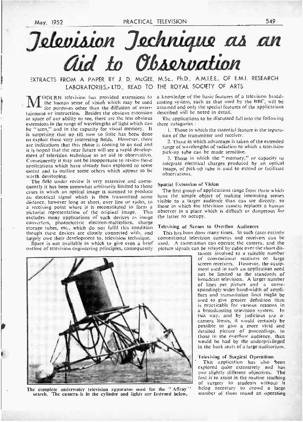
Tr
May, 1952 PRACTICAL TELEVISION 549
Jthvithii ,7ulvziyca cu an (.id ív 6.6.412Avatitin
EXTRACTS FROM A PAPER BY J. D. McGEE, M.Sc., Ph.D., A.M.I.E.E., OF E.M.I. RESEARCH
LABORATORIES,- LTD., READ TO THE ROYAL SOCIETY OF ARTS
MODERN television has provided extensions to the human sense of vision which may be used for purposes other than the diffusion of enter-
tainment or instruction. Besides the obvious extension in space of our ability to see, there are the less obvious extensions in the range of wavelengths of light which can be " seen," and in the capacity for visual memory. It is surprising that up till now so little has been done to exploit these very interesting fields. However, there are indications that this phase is coming to an end and it is hoped that the near future will see a rapid develop- ment of television technique as an aid to observation. Consequently it may not be inopportune to review those applications which have already been explored to some extent and to outline some others which appear to be worth developing.
The field under review is very extensive and conse- quently it has been somewhat arbitrarily limited to those cases in which an optical image is scanned to produce an electrical signal which is then transmitted some distance, however long or short, over line or radio, to a receiving point where it is reconstituted to form a pictorial representation of the original image. This excludes many applications of such devices as image converters, photoelectric electron- multipliers, charge storage tubes, etc., which do not fulfil this condition though these devices are closely connected with, and largely owe their development to, television technique.
Space is not available in which to give even a brief ontline of television engineering principles, consequently
a knowledge of the basic features of a television broad- casting system, such as that used by the BBC, will be assumed and only the special features of the applications described will be noted in detail.
The applications to be discussed fall into the following three catagories:
1. Those in which the essential feature is the separa- tion of the transmitter and receiver.
2. Those in which advantage is taken of the extended range of wavelengths of radiation to which a television pick -up tube can be made sensitive.
3. Those in which the " memory," or capacity to integrate electrical charges produced by an optical image, of pick -up tube is used to extend or facilitate observations.
Spatial Extension of Vision The first group of applications range from those which
have the simple object of making interesting scenes visible to a larger audience than can see directly, to those in which the television camera replaces a human observer in a place which is difficult or dangerous for the latter to occupy.
Televising of Scenes to Overflow Audiences This has been done many times. In such cases entirely
conventional television cameras and receivers can be used. A cameraman can operate the camera, and the picture signals can be relayed by cable over the short dis-
tances involved to a suitable number of conventional receivers or large screen receivers. However, the equip- ment used in such an application need not be limited to the standards of broadcast television. A larger number of lines per picture and a corre- spondingly wider band -width of ampli- fiers and transmission lines might be used to give greater definition than is practicable for various reasons in a broadcasting television system. In this way, and by judicious use o camera lenses, it would certainly be possible to give a more vivid and detailed picture of proceedings, to those in the overflow audience, than would be had by the underprivileged in the back seats of a large auditorium.
The complete underwater television apparatus used for the " Affray " search. The camera is in the cylinder and lights are fastened below.
Televising of Surgical Operations This application has also teen
explored quite extensively and has two slightly different objectives. The first is to assist in the routine teaching of surgery to students without It being necessary to crowd a large number of them round an operating
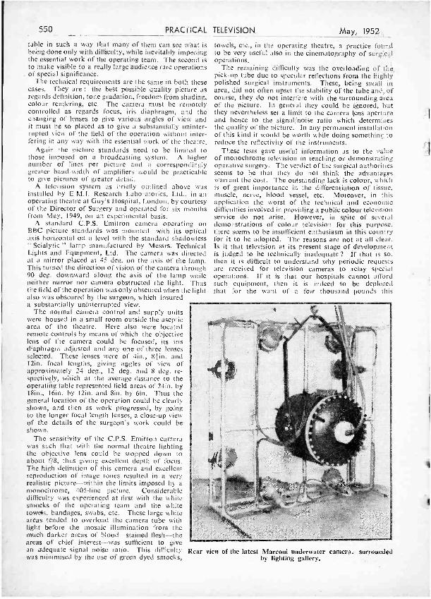
550 PRACTICAL TELEVISION May, 1952
table in such a way that many of them can see what is being done only with difficulty, while inevitably impeding the essential work of the operating team. The second is to make visible to a really large audience rare operations
. of special significance. The technical requirements are the same in both these
cases. They are : the best possible quality picture as regards definition, tone gradation, freedom from shading, colour rendering, etc. The camera must be remotely controlled as regards focus, iris diaphragm, and the changing of lenses to give various angles of view and it must be so placed as to give a substantially uninter- rupted view of the field of the operation without inter- fering in any way with the essential work of the theatre.
Again the picture standards need to be limited to those imposed on a broadcasting system. A higher number of lines per picture and a correspondingly greater band -width of amplifiers would be practicable to give pictures of greater detail.
A television system as briefly outlined above was installed by E.M.I. Research Laboratories, Ltd., in an operating theatre at Guy's Hospital, London, by courtesy of the Director of Surgery and operated for six months from May, 1949, on an experimental basis.
A standard C.P.S. Emitron camera operating on BBC picture standards was mounted with its optical axis horizontal on a level with the standard shadowless " Scialytic " lamp manufactured by Messrs. Technical Lights and Equipment, Ltd. The camera was directed at a mirror placed at 45 deg. on the axis of the lamp. This turned the direction of vision of the camera through 90 deg. downward along the axis of the lamp while neither mirror nor camera obstructed the light. Thus the field of the operation was only obscured when the light also was obscured by the surgeon, which insured a substantially uninterrupted view.
The normal camera control and supply units were housed in a small room outside the aseptic area of the theatre. Here also were located remote controls by means of which the objective lens of the camera could be focused, its iris diaphragm adjusted and any one of three lenses selected. These lenses were of 4in., 8 }in. and 12in. focal lengths, giving angles of view of approximately 24 deg., 12 deg. and 8 deg. re- spectively, which at the average distance to the operating table represented field areas of 24in. by 18ín., 16in. by 12in. and Bin. by 6in. Thus the general location of the operation could be clearly shown, and then as work progressed, by going to the longer focal length lenses, a close -up view of the details of the surgeon's work could be shown.
The sensitivity of the C.P.S. Emitron camera was such that with the normal theatre lighting the objective lens could be stopped down to about f /8, thus giving excellent depth of focus. The high definition of this camera and excellent reproduction of image tones resulted in. a very realistic picture -within the limits imposed by a monochrome, 405 -line. picture. Considerable difficulty was experienced at first with the white smocks of the operating team and the white towels, bandages, swabs, etc. These large white areas tended to overload the camera tube with light before the mosaic illumination from the much darker areas of blood -stained flesh -the areas of chief interest -was sufficient to give an adequate signal noise ratio. This difficulty was minimised by the use of green dyed smocks,
towels, etc., in the operating theatre, a practice found to be very useful also in the cinematography of surgical operations.
The remaining difficulty was the overloading of the, pick -up tube due to specular reflections from the highly polished surgical instruments. These, being small in area, did not often upset the stability of the tube and, of course, they do not interfere with the surrounding area of the picture. In general they could be ignored, but they nevertheless set a limit to the camera lens aperture and hence to the signal,'noise ratio which determines the quality of the picture. In any permanent installation of this kind it would be worth while doing something to reduce the reflectivity of the instruments.
These tests gave useful information as to the value of monochrome television in teaching or demonstrating operative surgery. The verdict of the surgical authorities seems to be that they do not think the advantages warrant the cost. The outstanding lack is colour, which is of great importance in the differentiation of tissue, muscle, nerve, blood vessel, etc. Moreover, in this application the worst of the technical and economic difficulties involved in providing a public colour television service do not arise. However, in spite of several demonstrations of colour television for this purpose, there seems to be insufficient enthusiasm in this country for it to be adopted. The reasons are not at all clear. Is it that television at its present stage of development is judged to be technically inadequate? If that is so, then it is difficult to understand why periodic requests are received for television cameras to Belay special operations. If it is that our hospitals cannot afford such equipment, then it is indeed to be deplored that for the want of a few thousand pounds this
Rear view of the latest Marconi underwater camera. surrounded by lighting gallery.
May, 1952
field of development must be neglected in this country.
In the United States the attitude seems to be different. To give only one example, the University of Kansas Medical Centre has used monochrome television for the past two years and has just installed a colour system and reports very satisfactory results. (See Tune, December 10th, 1951.)
PRACTICAL TELEVISION 551
Submarine Television This is the first of the examples of applications in
which a television camera takes the place of a human observer in a place where it is difficult or dangerous for a man to operate. This application was brought dramatically to the notice of the public in September last by the announcement by the Admiralty that the sunken submarine Affray had been identified by this means lying at a depth of 285ft. on the bottom of the English Channel using an image orthicon camera made by'the Marconi Wireless Telegraph Co.
Divers have been going down in diving suits, diving bells and sealed chambers for some decades, with and without artificial illumination, and television cameras have been operated at distances of up to 1,000ft. from their control unit for some 15 years and could be remotely operated at much greater distances if required. Al the important technical problems involved in submerging a television camera had already been encountered and overcome in using cameras add cine cameras under water with and without artificial illumination, and these problems are negligible compared with the difficulties arising and precautions necessary in the operation of a diver. Hence it is somewhat surprising that the first use of this potentially valuable equipment was made only in 1951. In October, 1939. the author and his colleague, Mr. H. E. Holman, attempted unsuccessfully to get this promising field for television explored and pointed out the advantages to be gained in a memorandum submitted at that time.
Before the war the most sensitive television camera compared quite well with the standard 35 mm. cine- matograph film but not with the human eye in sensitivity. However, the improvement in the sensitivity of television cameras has been very rapid and now it is fair to say that the television camera compares with the sensitivity of the eye in the " light -adapted," or photopic, state. It is true that the eye in the dark -adapted, i.e. the scotopic, state, is still an order of magnitude more sensitive than the best television camera, but it then loses its ability to distinguish detail and colour. When a BBC television commentator under conditions of bad light has said that he could see more clearly what was going on by reference to the television commentator's monitor than by looking directly at the scene it was probably due to his eyes being in the photopie Condition through looking at his monitor. The eye only attains its full sensitivity after being in the dark for as much as 30 minutes and then it can see fairly well in moonlight - equivalent to the illumination of 0'01 feet candles - while no television camera known to the author will give an intelligible picture of moving objects with less than 0,11 foot candles.
Hence, although the human eye of the diver can still see better in poor light under water than the television camera, the latter has so many other fundamental advantages that it seems inevitable that it will open up a vast field of exploration and research in the hitherto almost unknown depths of the oceans. These advantages may be listed as follows
I. Diving is hazardous work and a television camera
can be risked when a diver could not be allowed to risk his life.
2. Diving is a skilled occupation only done by specially trained men who cannot be expected to be experts in any of the highly technical subjects they must examine. All the technical expert can obtain at the surface is a description of what has been seen by a layman.
3. If the diver operates in a " soft " diving suit which allows him mobility, the depth to which he can go is limited and he must be raised very slowly to avoid cramp due to the release of excess nitrogen dissolved in his blood at the high air pressure necessary at great depths. This is a serious hazard and limits the scope of a diver's operations very considerably. With all the latest aid the record depth of dive is only 540ft.
4. Strong tides, bad weather and other considerations may severely limit the time when a diver can work with reasonable safety. This could be extended by the use of a television camera.
5. All of these points have been illustrated in the case of the Affray, and how much more vitally important might they not become in a case in which a disabled submarine was not overwhelmed as rapidly as that ill -fated craft.
The diver operating in a flexible diving suit has still one big advantage : he can manipulate tools, etc., while the camera can only look on. However, it seems inevitable that in the near future the camera will be provided with remotely operated arms and hands so that operations can be done by remote control while being observed and directed by the television camera, as is now the practice in plutonium separation plants.
Besides the application to examination of wrecked ships there is the tremendous field of scientific exploration of the ocean bed, and the plant and animal life of the ocean. In view of the urgency of the food problems of the world it is to be hoped that submarine television may be able to make some contribution to exploiting that vast potential source of food, the ocean.
Scottish Recommendation Some three years ago Dr. H. Barnes, of the Scottish
Marine Biological Association, proposed that a sub- marine television equipment should be built and tested for this purpose. An application was made to the Treasury by the Scottish Marine Biological Association under their president, Prof. C. M. Young, F.R.S., for a grant from the development fund. The application was considered by the Development Commission's Advisory Committee for Fisheries Research, who recommended that a grant should be made, and who appointed a scientific group to keep in close contact with the work. This grant was authorised early in 1951, and shortly afterwards a contract was placed with E.M.I. Research Laboratories, Ltd., for the construction of suitable equipment.
In this application the camera will be mounted in a strong steel case, which has a glass window in front of the operative lens and a watertight gland through which the camera cable is brought through the steel cover plate. The camera itself is of the C.P.S. Emitron type, rather similar to that used in the operating theatre, without viewfinder, of course, but with remote control of optical focus, lens iris and lens turret. The camera control equipment will be standard portable units, which can be located at any convenient place on the surface. Water- tight lamps, rigged on arms extending from the camera case, are provided to illuminate objects in the water or on the sea bed.
(To be continued.)
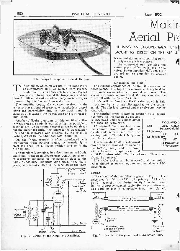
552 PRACTICAL TELEVISION
The complete amplifier without its case.
THIS amplifier, which makes use of an inexpensive ex- Government unit, obtainable from Premier Radio and other advertisers, has been designed
for those who are living beyond the fringe area, and for those in difficult situations where reception is weak, or is marred by interference from traffic, etc.
The amplifier boosts the voltages received in the aerial so that a signal of reasonable magnitude is passed along the transmission line. A very weak signal is seriously attenuated if the transmission line is of reason- able length.
Another difficulty overcome by this amplifier is that in weak areas the aerial is erected as high as possible in order to pick up as strong a signal as can be obtained ;
but the higher the aerial, the longer is the transmission line and the increased gain obtained by the height is partially .offset by the additional loss in the line.
On the fringe, trouble is often experienced with interference from passing traffic. A remedy is to erect the aerial in a higher position and to fit the pre -amplifier.
The amplifier is contained in a sleek, streamlined body, and is built from an ex- Government U.H.F. aerial unit. It is actually mounted on the aerial as close to the dipole as possible. The prototype (shown in the photo- graph) was actually fitted at the junction of the cross-
n R4 H.T+ 4.7Kí1 250V.
To Dipole
Coax. Input to
Receiver
C2 2 SOOpF. 150f2
Fig. 1.- Circuit of the Aerial Pre -Amplifier.
Earth
LT+ 6.3V
May, 1952
Malair Aerial PrE
UTILISING AN EX- GOVERNMENT UNII
MOUNTING DIRECT ON THE AERIAL
boom and the main supporting mast. It weighs only a few ounces.
The completed unit contains the entire pre -amplifier with the 6F12 valve. Power supplies (H.T. and L.T.1 are fed to the amplifier by coaxial cables.
Dismantling the Unit The general appearance of the unit is shown in the
photographs. The top lid is removable, being held by three sunk screws which are covered with wax. The screws are easily removed and the top can then be prised off with the blade of a knife.
Inside will be found an EA50 valve which is held in position by a springy clip attached to the copper aerial. The clip is unscrewed and the valve can then be removed.
The existing aerial is held in position by a locking nut fitted on the baseplate ; the nut is unscrewed and the copper aerial can then be withdrawn.
To separate the baseplate from the ebonite cover undo all the countersunk screws, and also the locking nuts. The black body can then be withdrawn.
The baseplate holds a cylindrical cover which is removed by undoing two locking nuts ; inside this cover will be found a three -pin socket and a 100 Kf2 resistor with a 20 pF condenser. These items should be removed.
The EA50 socket can be removed and the hole it leaves should be opened out to accommodate a B7G valve buse.
COIL -WIND Coil Alex. Sutton
Palace Coldfiel, Ll Primary
2T l ¡T L1 Secondary
7T 5T L2 Primary as L2 Secondary
Circuit The circuit of the amplifier is given in Fig. 1. The
valve used is a Mazda 6F12. The primary of LI is fed by 80 n coaxial or twin feeder directly from the dipole. In the prototype coaxial cable tin. overall diameter was used so that it completely filled the hole left
L.T+ LT+ iKf+ Power Line NT
Transmission Line
Common Earth
Pre -Amp. unit (at top of aerial
support
First coil in
receiver
Fig. 2.- Details of the power and transmission lines.
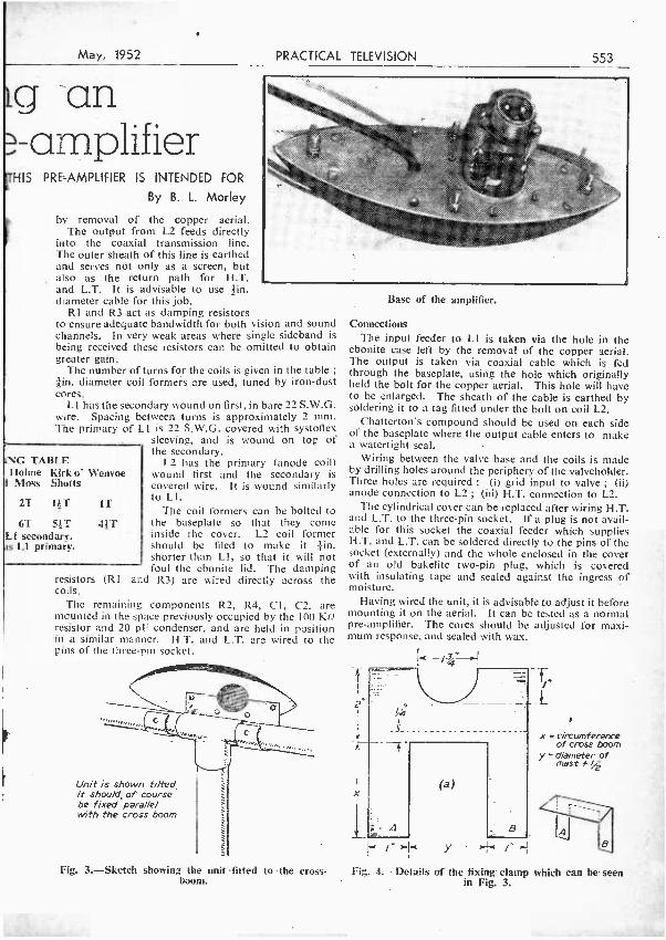
May, 1952
g an - amplifier
HIS PRE- AMPLIFIER IS INTENDED FOR
By B. L. Morley
by removal of the copper aerial. The output from L2 feeds directly
into the coaxial transmission line. The outer sheath of this line is earthed and serves not only as a screen, but also as the return path for H.T. and L.T. It is advisable to use tin. diameter cable for this job.
RI and R3 act as damping resistors to ensure adequate bandwidth for both vision and sound channels. In very weak areas where single sideband is being received these resistors can be omitted to obtain greater gain.
The number of turns for the coils is given in the table ;
ern. diameter coil formers are used, tuned by iron -dust cores.
LI has the secondary wound on first, in bare 22 S.W.G. wire. Spacing between turns is approximately 2 mm. The primary of LI is 22 S.W.G. covered with systofiex
sleeving, and is wound on top of the secondary.
L2 has the primary (anode coil) wound first and the secondary is covered wire. It is wound similarly to LI.
The coil formers can be bolted to 41T the baseplate so that they come
inside the cover. L2 coil former should be filed to make it tin. shorter than LI, so that it will not foul the ebonite lid. The damping
resistors (RI and R3) are wired directly across the coils.
The remaining components R2, R4, Cl, C2, are mounted in the space previously occupied by the 100 K!2 resistor and 20 pF condenser, and are held in position in a similar manner. H.T. and L.T. are wired to the pins of the three -pin socket.
PRACTICAL TELEVISION 553
NC TABLE Holme Kirk o' Wenvoe
Moss Shotts
21 1T 1T
6T 5T LI secondary.
Ll primary.
Unit is shown tilted It should, of course be fixed parallel with the cross boom
Fig. 3.- Sketch showing the unit fitted to the cross - boom.
Base of the amplifier.
Connections The input feeder to LI is taken via the hole in the
ebonite case left by the removal of the copper aerial. The output is taken via coaxial cable which is fed through the baseplate, using the hole which originally held the bolt for the copper aerial. This hole will have to be enlarged. The sheath of the cable is earthed by soldering it to a tag fitted under the bolt on coil L2.
Chatterton's compound should be used on each side of the baseplate where the output cable enters to make a watertight seal.
Wiring between the valve base and the coils is made by drilling holes around the periphery of the valveholder. Three holes are required : (i) grid input to valve ; (ii) anode connection to L2 ; (iii) H.T. connection to L2.
The cylindrical cover can be replaced after wiring H.T. and L.T. to the three -pin socket. If a plug is not avail- able for this socket the coaxial feeder which supplies H.T. and L.T. can be soldered directly to the pins of the socket (externally) and the whole enclosed in the cover of an old bakelite two -pin plug, which is covered with insulating tape and sealed against the ingress of moisture.
Having wired the unit, it is advisable to adjust it before mounting it on the aerial. It can be tested as a normal pre -amplifier. The cores should be adjusted for maxi- mum response, and sealed with wax.
f
-:: A
(a)
B
-Fe
.
x =circumference of cross boom
y = diameter of mast * /2
Fig 4.- Details of the fixing clamp which can be seen in Fig. 3.
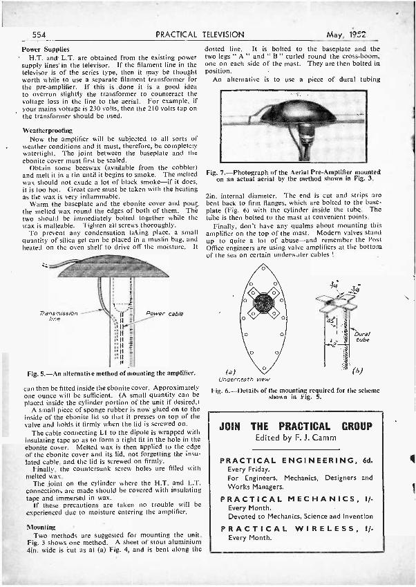
554 PRACTICAL TELEVISION May, 1952
Power Supplies H.T. and L.T. are obtained from the existing power
supply lines in the televisor. If the filament line in the televisor is of the series type, then it may be thought worth while to use a separate filament transformer for the pre- amplifier. If this is done it is a good idea to overrun slightly the transformer to counteract the voltage loss in the line to the aerial. For example, if your mains voltage is 230 volts, then the 210 volts tap on the transformer should be used.
Weatherproofing Now the amplifier will be subjected to all sorts of
weather conditions and it must, therefore, be completely watertight. The joint between the baseplate and the ebonite cover must first be sealed.
Obtain some beeswax (available from the cobbler) and melt it in a tin until it begins to smoke. The melted wax should not exude a lot of black smoke -if it does, it is too hot. Great care must be taken with the heating as the wax is very inflammable.
Warm the baseplate and the ebonite cover and pour the melted wax round the edges of both of them. Thé two should be immediately bolted together while the wax is malleable. Tighten all screws thoroughly.
To prevent any condensation taking place, a small quantity of silica gel can be placed in a muslin bag, and heated on the oven shelf to drive off the moisture. It
Transmission line
Power cable
dotted line. It is bolted to the baseplate and the two legs " A " and " B " curled round the cross -boom, one on each side of the mast. They are then bolted in position.
An alternative is to use a piece of durai tubing
Fig. 7.- Photograph of the Aerial Pre -Amplifier mounted on an actual aerial by the method shown in Fig. 3.
tin. internal diameter. The end is cut and strips are bent back to firm flanges, which are bolted to the base - plate (Fig. 6) with the cylinder inside the tube. The tribe is then bolted to the mast at convenient points.
Finally, don't have any qualms about mounting this amplifier on the top of the mast. Modern valves stand up to quite a lot of abuse -and remember the Post Office engineers are using valve amplifiers at the bottom of the sea on certain underwater cables !
Fig. 5. -An alternative method of mounting the amplifier. (e) Underneath view
Fig. 6.- Details of the mounting required for the scheme shown in Fig. 5.
can then be fitted inside the ebonite cover, Approximately one ounce will be sufficient. (A small quantity can be placed inside the cylinder portion of the unit if desired.)
A small piece of sponge rubber is now glued on to the inside of the ebonite lid so that it presses on top of the valve and hohis it firmly when the lid is screwed on.
The cable connecting LI to the dipole is wrapped with insulating tape so as to form a tight fit in the hole in the ebonite cover. Melted wax is then applied to the edge of the ebonite cover and its lid, not forgetting the insu- lated cable, and the lid is screwed on firmly.
Finally, the countersunk screw holes are filled with melted wax.
The joint on the cylinder where the H.T. and L.T. connections are made should be covered with insulating tape and immersed in wax.
If these precautions are taken no trouble will be experienced due to moisture entering the amplifier.
Mounting Two methods are suggested for mounting the unit.
Fig. 3 shows one method. A sheet of stout aluminium 4in. wide is cut as at (a) Fig. 4, and is bent along the
3/q
Dural tube
JOIN THE PRACTICAL CROUP Edited by F. J. Camm
PRACTICAL ENGINEERING, 6d. Every Friday. For Engineers, Mechanics, Designers and Works Managers.
PRACTICAL MECHANICS, I/- Every Month. Devoted to Mechanics, Science and Invention
PRACTICAL WIRELESS, I/- Every Month.
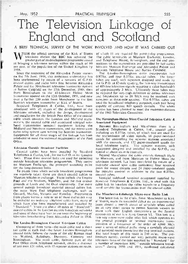
May, 1952 PRACTICAL TELEVISION 555
The Television Linkage of England and Scotland
A BRIEF TECHNICAL SURVEY OF THE WORK INVOLVED AND HOW IT WAS CARRIED OUT
V\71TH the official opening of the Kirk o' Shotts television station the BBC has achieved the greater part of its development programme aimed
at bringing a television service within the reach of 80 per cent. of the population of the United Kingdom by 1954.
Since the reopening of the Alexandra Palace station on,the 7th June, 1946, this ambitious undertaking has been implemented by means of a network of G.P.O. coaxial cables and radio links first between Alexandra Palace and the 30- kilowatt television transmitter opened at Sutton Coldfield on the 17th December, 1949, then from Birmingham to the 45- kilowatt Holme Moss transmitter opened on the 12th October, 1951, and now over a further 250 miles from Manchester to the first Scottish television transmitter at Kirk o' Shotts.
Standard Telephones & Cables, Ltd., have been associated with all stages of the development of the television network, including the design, development and installation for the British Post Office of the coaxial cable which connects the London and Midland trans- mitters, the coaxial cable and associated vestigial side - band transmission terminal equipment linking the Midland and Northern transmitters, and the micro -wave radio relay system now serving the Scottish transmitter. Equipment for all three stages of the linkage has been produced to meet the technical requirements of the Post Office.
Television Outside Broadcast Facilities Coaxial cables have been installed by Standard
Telephones & Cables, Ltd., for the G.P.O. in the London Area. These short coaxial links are used for collecting outside broadcast television programmes. They centre on Museum Exchange, the principal switching point for the long- distance links.
To places from which outside broadcast programmes are regularly taken there are direct coaxial cables to Museum telephone exchange. These include the Empire Pool and the Stadium, Wembley, and the two cricket grounds at Lords and the Oval respectively. For more general outside broadcast material coaxial cables link the main West End telephone exchanges, such as Gerrard, Mayfair, Victoria and Faraday. Programmes from places within a mile or so of these exchanges may be collected on ordinary telephone cable lines, many of which have also been manufactured and installed by " Standard." There arc.about 40 miles of " Standard " coaxial cables in the London ouside broadcast networks and sonie of these have been in use since the beginning of television broadcasting from Alexandra Palace in 1936.
The London- Birmingham Coaxial Television Cables Consisting of three parts -the main cable and a short
tail cable at each end -the latest London- Birmingham coaxial cable follows the route of the old Roman road via Watford, Aylesbury, Daventry, Coventry and Birmingham. The main cable, forming part of the Post Office trunk,telephone network, covers a distance of Inst over 121 miles, with 43 repeater stations en route,
of which 11 are required for present -day programmes. The cable terminates at Museum Exchange, London, and Telephone House, Birmingham, and the end con- nections to the transmitters are provided by tail cables between Museum Exchange and Alexandra Palace and between Telephone House and Sutton Coldfield.
The London -Birmingham cable incorporates two 0.975in. and four 0.375in. coaxial tubes. The larger tubes are used, with repeaters designed and made by the G.P.O. at 12 -mile spacing, for two -way transmission of 405 -line television signals requiring a video bandwidth of approximately 3 Mc /s. Ultimately these tubes may be required for very- high- definition or colour television and frequencies up to 26 Mc /s may be involved with repeaters at three -mile spacing. The 0.375in. tubes are used for broadband telephony purposes, each pair being capable of carrying 600 speech circuits. The whole system has been planned to meet the recommendations of the 1943 Television Committee.
The Birmingham -Holme Moss Coaxial Television Cable & Associated Equipment
Between Birmingham and Manchester there is a Standard Telephones & Cables, Ltd., coaxial cable including six 0.375in. tubes, of which two are used for the transmission of video signals, 16 paper -insulated quads for controlling the repeater stations associated with the coaxials, and 172 paper -insulated quads for local telephone traffic. The repeater stations, with equipment designed and installed by the G.P.O., are spaced at about six -mile intervals.
Beyond Manchester the cable extends through Hyde to Mottram, and from Mottram to Holme Moss the television network has been completed by means of a two -tube coaxial spur cable containing four screened pairs for music circuits and 24 paper- insulated quads for repeater control in addition to the two 0.375ín. coaxial tubes.
Vestigial sideband terminal equipment supplied by Standard Telephones & Cables. Ltd., is used with this cable link to translate the video signals to a frequency band suitable for transmission over the coaxial cable.
The Manchester -Edinburgh Micro -wave Radio Link The latest link in the chain, from Manchester to Kirk
o' Shotts, made its successful début on an experimental basis almost a month ahead of schedule when called on at very short notice to permit Scottish viewers to share with their English compatriots in the funeral ceremonies of our late King George VI. This link is a two -way micro -wave radio relay link which operates on the general principle of beamed micro -wave trans- missions at a frequency of the order of 4,000 Mc /s over a series of optical paths along a carefully planned and surveyed route connecting the two terminal stations. The total length of this route is 250 miles. The pre- liminary survey, carried out with portable micro -wave television links of the type supplied by " Standard " for a number of important BBC " outside television broad- casts" during 1950 and 1951, confirmed calculated
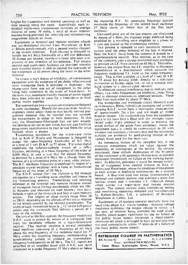
556 PRACTICAL TELEVISION May, 1952
heights for transmitter and receiver antennae as well as their spacing along the route. Accordingly, each in- dividual micro -wave transmission traverses an average distance of some 30 miles, a total of seven repeater stations being provided for receiving and retransmitting programme signals en route.
Equipment at terminal and repeater stations affords one uni- directional channel from Manchester to Kirk o' Shotts simultaneously with a second similar channel in the reverse direction. Each channel is designed to handle the 0 -3 Mc /s bandwidth of a 405 -line definition, 50 frames per second, double- interlaced television pro- gramme in one direction of transmission. Full remote control and supervisory facilities are provided whereby each terminal station is able to control the operation of the equipment at all points along the route to the other terminal.
To ensure a high degree of reliability, all transmission equipment with the exception of parabolic reflectors and main waveguide feeds is provided in duplicate ; the change -over from one set of equipment to the other being fully automatic in the event of breakdown. in the same way, automatic standby sources of power supply have been provided to cater for a breakdown in local public mains supplies.
The intermediate two -way repeater stations are designed to work unattended. Should the occasion arise, however, engineers could adopt them so that locally derived pro- gramme material may be injected into the network for transmission in either or both directions. In this way, the Manchester -Edinburgh link not only extends the television service to new areas, but can also facilitate programme contributions to that service from the areas through which it passes.
Transmitting equipment for the micro -wave radio link at Kirk o' Shotts and Manchester is designed to accept the video -frequency bandwidth of 0 -3 Mc /s
at a level of 1 volt U.A.P. in 75 ohms. The video signal modulates the reflector -cathode circuit of a reflex klystron, oscillating at a basic frequency of the order of 4,000 Me/s, in such a way that the output frequency is deviated by a total of 6 Mc /s for a change from the bottom of a synchronising pulse to a peak white picture. The R.F. oscillator frequency is stabilised by means of a
precision crystal oscillator with a basic or fundamental frequency of the order of 20 Mc, /s.
The S.H.F. output from the klystron is fed through waveguides to a travelling wave atnplifier and thence to the transmitting antenna. Transmitting and receiving antennae at the terminal and repeater stations consist of waveguide horns feeding paraboloids which are loft. in diameter and mounted on steel towers ; two para- boloids at each of the terminals and four at each repeater station. The heights of these towers range from 20
to 200 ft. depending on the altitude of the site in relation to the terrain covered by the beamed transmission. The width of each transmitted beam is f l .° to the half -power points and the waveguide feed delivers a power of 1
watt to the antenna. On arrival at the first repeater the frequency modulated
S.H.F. wave is passed by means of a waveguide feed
from the parabolic reflector to a super -heterodyne receiver. This receiver employs a crystal controlled local oscillator operating at a frequency of 60 Mc /s
above the mid -frequency of the incoming signal (or 57
Mc /s above the incoming frequency corresponding to
synchronising pulses) to produce an intermediate - frequency band -centred on 60 Mc's. The I.F. signals are amplified in an amplifier fitted with A.V.C. and again translated to a radio frequency 37 Mc /s above or below
the incoming R.F. An automatic frequency control maintains the frequency of the second local oscillator 37 Mc /s above or below that of the first local oscillator.
Unwanted products of the last process are eliminated by means of a filter, the required single sideband being amplified by a travelling wave amplifier to a power of 1 watt and passed to the transmitting antenna.
This process is repeated at each successive repeater station until the other terminal of the link is reached. Here the S.H.F. band from the antenna is passed to a superheterodyne receiver. This receiver, as in the case of the repeaters, uses a crystal controlled local oscillator to produce an I.F. band centred on 60 Mc /s. Thereafter. however, the output from the I.F. amplifier is frequency demodulated in a discriminator which converts the frequency modulated I.F. band to the video frequency range. This is then available at a level of 1 volt D.A.P. in 75 ohms for passing either directly to a television transmitter or further radio link, or via a vestigial side - band system to a coaxial cable network.
To eliminate mutual interference due to multiple path effects, two radio frequencies are employed, these being used in alternate directions on alternate sections. These differ from each other by about 37 Mc /s.
The waveguides and waveguide circuit elements such as attenuators, filters, hybrid -type junctions and switches carrying S.H.F. waves have a rectangular cross- section of approximately tin. X tin. and are made of either brass or copper. The waveguide run from the equipment racks to the horn feed is filled with dry nitrogen main - tained'under slight pressure in order to preserve the inside surface of the guide from corrosion. Inside the equipment racks it would be inconvenient to fill with nitrogen and maintain a hermetic seal and the waveguide surfaces are protected by gold -plating instead of the varnish finish used for the main run.
An interesting feature of the complete link is the elaborate precautions which are taken against the possibility of interruption of the service. As already mentioned, these include duplication of the majority of the equipment with automatic change -over to standby equipment immediately on failure of the working equip- ment. In addition, provision is made for remote switch- ing of equipment from control stations at Kirk o' Shotts and Manchester, where the condition of equipment at each station is displayed continuously on a control board. A four -wire land line circuit interconnects all terminal and repeater stations and provides a party line speaker circuit and a two -tone V.F. telegraph circuit which carries the supervisory and remote control signals. The remote control desks incorporate testing and monitoring apparatus designed and manufactured by Kolster- Brandes, Ltd., a subsidiary of Standard Telephones & Cables, Ltd.
Equipment at all stations operates normally from the local three -phase A.C. mains supplies ; dynamic voltage regulators stabilising the output voltage to within ± 1
per cent. of nominal being provided for each phase. Standby power -supply equipment for use on failure of the public mains supply comprises a diesel- engine- alternator set which is arranged to start up and take over the load automatically within 15 seconds of a failure of the local public mains supply.
REFRESHER COURSE IN MATHEMATICS 8/6, by post 9/- 4th Edition By F. J. CAMM
From : GEORGE NEWNES LTD. Tower House, Southampton, Street, Strand, W.C.2
t
r
May, 1952 PRACTICAL TELEVISION 557
A /lea/ WINDSQR TEST METER
20,000 Q.p.v. MODEL TTA
Please write for illustrated leaflet featuring our new range of radio and television test gear.
An entirely new instrument incorporating the latest improvements in manufacturing technique. Refinements include shockproof moulded case, clear and easy to read scales and many other features.
SENSITIVITY 20,000 ohms per 5,000 ohms per
VOLTS D.C.: 0 -7. -300 -750-3,
VOLTS A.C. : 0 -7. -300 -750.
METER volt D.C. Precision engineered mov- volt A.C. ing coil, fitted with 5in.
scale and knife edge pointer.
RANGES 5 -30-75 MILLIAMPS D.C. : 0-.15
000. -1.5 -15- 150 -1,500. 5 -30 -75 AMPERES D.C.: 0-15.
RESISTANCE : 10 ohms- OUTPUT. As for A.C. 5 megohrils in two ranges, volt ranges except 3,000v., self contained. via a condenser.
List Price L15. 0 .0
TAYLOR ELECTRICAL INSTRUMENTS LTD. 419 -424, MONTROSE AVENUE, SLOUGH, BUCKS. Phone : SLOUGH 21381.
OIIiIIil1111Illilll»II,IIIIiIIIIil1111111UI,1111111,1111: H EN RV' SIIIIIIIIII1I1I111111IiN111111111111111ü1111Ii111111111ti1i1 " PYE " 45 MC /S STRIP. Special purchase of M.O.S. Type 3583 Unit, size 15in. x 8fn. x 2in. Complete with 45 me /s Pye Strip, 12 Valves, 10 EF50, EB34 and EA50, Volume controls and a host of Resistors and Condensers. Sound and vision can be Incorporated on this chassis with minimum of space. New condition. Price £5, carriage paid. FOUR SECTION CHASSIS adaptable for the " Argus " Television lay -out, 211- carr. pd. 182A UNIT. Containing VCR517. 619. C.R. Tube. Mu -metal shield. 3 EF50, 5 SP61. 5U9G. 9 W/W Pots. Resistors and Conden- sers. Tag boards. Tube guaranteed for TV. (No cut -off). Or suitable for Scope. Brand New, less relay. In original packing case. 79/8. plus 7,6 carriage. CATHODE RAY TUBES. VCR97 Brand New. Guaranteed Full Picture 45!- carriage paid. VCR139A. Brand New. Suitable for Scopes 351 - 3BP1. Brand New. Suitable foc Scopes 25'- " 94n. ESCUTCHEON. Brown Bakelite. Suitable Plate glass and Mask for Sin. Tube. Price 7/8 each.
* A COMBINED SIGNAL TRACER AND AUDIO OSCILLATOR * An easy -to -build unit that can be used for I.F. and Audio signal tracing, without any switching or tuning, including variable out - put oscillator, for amplifier checking. Highly sensitive, responds to signals picked up from an ordinary receiving aerial. The circuit is that of a high -gain 2- stage, resistance -coupled audio frequency amplifier, employing 3 miniature 1.4 valves, with a 3 -inch speaker in the output of the Power Amplifier Stage. An added advantage being that as this Unit is " All -Dry " it can be used with safety on A.C. or A.0 /D.C. mains and Battery sets. The complete Kit with portable cabinet (size 61n. x 71e. x Bin.) and bat- tery weighs only 4 lbs. - We shall be pleased to supply a complete Kit for the construction of the above. right down -to the last nut and bolt, including 2 -IT4 and 1 -1S4 Valves, 3in. Spepker and Portable case and All-Dry Battery for £4/1916. Concise instructions and circuits supplied. If preferred, circuit and instructions only can be supplied for 1/6. If required this Unit will be assembled and tested for an extra charge of 15/ -. This is a highly efficient instrument, and a MUST for every radio man. METAL RECTIFIERS. -S.T.C. 300 volt 75 m /a, 8/- ; S.T.C. R.M.2, 150 volt 120 m /a, 4.6 ; G.E.C. 6 volt 1 amp., 4/- ; Westing- house 12 volt 2l amp., 12/8 : Westinghouse S.T.C. 12 volt 31 amp.. 17/8 : E.H.T. Penco Type, 600 volt 1 mua, 47 ; E.H.T. Pencil Type, 1,00a volt I. m'a, 6' -. -
RECEIVER. UNIT TYPE 159. Containing VR91. V11,92, VR55 and 2Av. Selector Switch, New condition 15,- (Post 1,6). KILT. TRANSFORMER for VCR97. Input 230v. Output 2.500v. 4v., 2 -0-2. 45/ , E.H.T. TRANSFORMER for 5CP1. Input 230v. Output 3.250v. 6.3v. at 0.6ma., 2-0-2v., 45' -. 5 K.V. STEWART E.R.T. TRANSFORMER. -Input 210/230250 volts. Output 5kV. and 4v. 1 amp. Insulation volts 6.500v. D.C., 79-6. WALKIE- TALKIE TYPE 49. Containing 6 Valves, 2 of VP23, HL23'DD, QP25, TP25, ATP4, 3 I.F.T.'s 1.6 Mes. Mike and Inter - valve Trans. Aerial Rods. etc. Metal case, size 121n. x bin. x 4in. In new condition but less transmitting components removed by the MOS. Price including carriage 351 -. -Limited quantity. PUSII PULL OUTPUT TRANSFORMER. U.S.A. potted type primary-10.900 f1 sec., 2 LI, 8 Q. LI Q, 15 watts, 21/ -.
GERMANIUM CRYSTAL DIODES, complete with full wiring circuit and diagram. 48, EX. -GOVT. V:.Ives. THE FOLLOWLIG ARE BRAND NEW :- EF50 Red Sylvanian. Original Boxes (U.S.A.), 10) -. F.F50 English Types. Original boxes, 8.-6. EF50 Ex Units. Guaranteed, 8- At 8 6 each EF50, EF54, EF55 CV66, EF8, EF36, EF39,' EK32 EL32, EBC33, 6K7GT, 6J7GT. 6L7GT. 6SK7GT, 6SJ7GT, 608GT. GN7GT, 6d5GT, 6C5GT, 6AC7GT, 6SA7GT, 6SH7GT, 6D6, 6C6, 12SA7GT, 12SK7GT, 12SJ7GT, 12SQ7GT, 12C8, 12SR7GT, 12SH7GT, I2AGGT. 14A7GT, 12Q7GT. 7A7GT, 7C7GT, 71Y70T, 7S7GT, 7B6GT, 41MP, 955. 9001, 9002. 9003, 1299A. 231)7, 902, 41)1. 1502. RECTI- FIERS AT 5'- each :- V U111,VU133, V U12OA, OZ416105. At Eve each :- 5Z4G, U50. 5Y3G. At 10 /- each : 6F7. ACEPEN MUH. 8AM6, 6VGGT, sum, 6Q7. GA8G, U52. BAGS, PEN46, 5169. 91E91. 80. At 128 each ,:- 12KBGT, BKBG, KT33C, 6SL7GT, 6SN7GT, 43, 6J8, 6L6, (1622 Metal). Also at 11'- :- 35L6GT. 50L6GT 01'61 (VR92), 3r- ; DI, 3/8 : E1334, 3/6 : VR65 (SP61). 5'- ; RLIB, 5/- : 959, 5/- ; 656,' 5/- : S130. 7 6. VR150 /30, VS70. VR105. E'6 : PX2e, 101 -. ALL DRY BATTERY VALVES. 3V4. 105, 11'9. 1S5. 1R5, ILNSGT. 1S4, 3S4. all at 10'- each. SP2, VP2. TDD2A. VP23, TP25, 11L23 DD. all at 8'6. 215SG, KT2, PEN220A. 61 -. P2 (Super -power), 4 -. RIVA CXH, 741. -
* SEND STAMPS OR 28 PAGE CATALOGUE * S HARROW ROAD, PADDINGTON, LbNDON, W.2. TEL: PADDINGTON 100019, 0401.
558 PRACTICAL TELEVISION May, 1952
R A N G E
`Here is your area *and here is your
Aerialite AER" AL
MODEL 65 "Aeradoor." Designed for indoor skirting -board mounting. Fitted with one telescopic and one flexible arm. Can be adjusted to any channel. Complete with 5 yards of coaxial lead -in. PRICE 321 -
MODEL 65A with 5 yards of Twin feeder. PRICE 321 -
Also MODEL 66, which has twoflexible arms. Complete. PRICE 2519
MODEL 66A, with 5 yards twin feeder. PRICE 2519
MODEL 74. Has three fully flexible ele- ments. High pickup properties. Trouble - free performance. Centre element has
a spring tensioning device and neat con- nector box. All Channels. PRICE 1316
MODEL 53 (similar to 74). Three rigid metal elements. Installed in variety of positions. All Channels. (Coaxial lead -in extra.)
PRICE 3216
MODEL 57. Single dipole for chimney stack mounting. Complete with chim- ney bracket, mast, lashings, etc., ready for installation. Excellent performance.
PRICE 6216
MODEL 58. A dipole designed for wall mounting. Cranked stand -off mast similar to Model 57. PRICE 5216 (58A with straight stand -off arm, 471 -.) All Channels.
MODEL 55. An H- aerial with dipole and reflector. Forward gain 3.8 dB. Fronti back ratio 11.0d B. Acceptance angle 180 deg. All Channels. Complete with a 10ft. x 2in. dural mast, brackets, lashings, etc. PRICE £711910. Other " H " type aerials available.
E. F. 50 TELEVISION VALVE GUARANTEED
RED (SYL) 61 -. VR9I,
SP6I ... 216 EA50 ... 21-
SP41 216 EB34 ... 21-
VUIIÌ 31- VU133 31-
CV66.. 416 PEN46 416
9001 , 31- 12SH7 416
12H6 ... 416 6H6 416
APT4... 51- VR 105130 616
5Z3 ... 716 5Z4 ... 1016
80 . 1016 6V6 ... 101-
6S K7 ... 516 6Q7 ... III- KT66 1216 TZ40 261- 6X5 ... 813 DI ... 21-
12A6 ... 716 615 ... 51-
EL50 ... 81-6N7 ... 616
616 ... 1216 6AG5... 81-
T41 .... 416 DSLIO 519
VT31 ... 1216 VU508 81-
51 -.
EF54 ... 416 EC52 ... 416 VU120A 31- 954 ... 31- 12517 416 6SH7 ... 613 VR150130 81- 5Y3 ... 1016
6K7 ... 619 6K8 ... 1216 I T4 ... 916 KT2 ... 41- VR56 71- 6AK5 913 2D21 ... 913 VP41 ... 41- VU504 3216
.1 mfd. CONDENSERS, 2.5 kV.. 416.
25, 50, 100, 150, 500pf., 61- per dczen. 8 mfd, 475v. (wire ends), 31 -. Tubular Can. 31 -.
POTENTIOMETERS. All Values to 2 Megs., 216.
Type 6H Indicators. E4. R1355, 651 -. Type 97 Indicators, complete (less valves and tube), 10!..
RESISTORS. Erie Insulated : -$.w, Iw., 251- per 100
mixed:
VINER 26 EAST ST., MIDDLESBROUGH
Tel. 3418.
MODEL 63A. For fringe and difficult reception areas. Folded dipole three .
element aerial. High gain 8.0 dB. Frontlback ratio 29 dB. Acceptance angle 90
deg. All Channels. Complete with 10ft. x 2in. dural mast, brackets, lashings, etc. PRICE E131510.With 14ft. mast, £141210. Various styles of this model available.
THIS FREE 104 PAGE BROCHURE describes the Courses of Training offered by E.M.I. Institutes -the only Postal College which is part of a world - famous Industrial Organisation.
Aero. Eng. Motor Eng. Draughtsmanship Elect. Eng. Prod. Eng. Management Languages Refrigeration Eng. Civil Service General Cert. of Education Radio, TV and Electronics University Train- ing Maths. Mech. Eng.
Heating and Ventilation Eng. Public Speaking Police Tele-
communications, etc. etc. Special Courses for A.M.I.Mech.E., A.M.I.C.E.,
Institutes A.M.I.P.E., A.M. Brit. I.R.E. p associated with A.P.R.Ae.s., City & Guilds
MARCONIPHONE v " IL
Examinations, etc.
COLUMBIA Post this for a FREE copy of "Successful Careers" to E.M.I.
iM.Y Institutes, Dept. 138, 43 Grove \" Park Road, Chiswick, London, W.4.
Name
Addree4
A NEW INDOOR AERIAL MODEL 71. A directional double folded dipole with four fully flexible elements. Easily erected in loft, attic or upper room.. Highly directional characteristics. Forward ga'n 3.75 dB. Excellent reception at considerable dis- tances from transmitters. Complete ready for erection to any channel specified. PRICE 251 -. Send 3d. stamps for FREE Illustrated Catalogue.
AERIALITE LTD., Stalybridge, Ches.
E.M.I.
ETC. COURSES FROM
El PER MONTH

May, 1952 PRACTICAL TELEVISION 559
Aerials and Signal Strength AN EXPLANATION, FOR THE BEGINNER, OF THE IMPORTANCE OF CORRECT SIGNAL STRENGTH
IT is often possible to see adjacent houses carrying totally different kinds of aerial, in some cases such extremes as a single dipole contrasting with a multi -
array with directors and reflector. The ,beginner may well ask what difference the aerial makes and wonder if the expense of the large aerial is justified. We often receive queries from prospective new viewers asking what type of aerial they should fit, and an attempt will there- fore be made to give some idea of the differences which may be expected from the various types of aerial. Firstly, to take the broad view, the simple aerial should be used in situations close to a station, whilst in remote areas the multi -array should be used. But this is not the whole story. When asked what type of aerial a reader should use our general reply (if we do not have first -hand informa- tion concerning the locality) is that it is not possible to state by just knowing that the situation is so many miles from the transmitter. It is possible to be situated 10 miles from a station and receive a poorer signal than at a point 50 miles away. As has been pointed out in these pages before, the signal follows the contour, more or less, of the ground, and thus at a point behind a hill it might be found that signals are completely absent, due to the screening effect of that hill. The same can apply to a large building, and a small villa situated behind it. On the other hand, where there is only a big stretch of open country without densely wooded areas, hills or buildings, the signal will travel uninterrupted and may be received over long distances at remarkable strength due to the nature of that country.
Signal Strength Some new viewers may think that they are not con-
cerned with powerful signals (taking their ideas from sound programmes) and imagine that a simple aerial will probably be good enough. This may be so, if the
. receiver is a model designed for long- distance reception. Most manufacturers now produce two types of receiver -one for normal distances and one for the remoter areas and generally known as a " fringe model." It is not necessary that the latter should be restricted to remote areas and it may be used, with certain_ precau- tions, in areas within a short distance of the transmitter. Firstly, it must be pointed out that it is not only the picture intelligence which must be considered when deciding upon the aerial. A much more important factor is the sync pulse which locks the picture and keeps it steady and intact. Both a weak pulse and a very strong one may be objectionable, and will give rise to several faults in the received picture. The commonest is known as " pulling on whites." where the picture becomes broken up in horizontal strips where a white object conies at the right -hand edge of the picture. All those scanning lines which terminate in the white detail will be seen to have moved to one side, resulting in any vertical lines in the picture being " stepped." As the white objects pass out of the picture the lines jump back into position and this obviously spoils what might otherwise be a good picture.
France Hold If there should be any local traffic it will also be
found that when a car passes, if it is not fitted with a
By W. J. Delaney (G2FMY)
suppressor, not only will the customary white dots be seen on the screen, but the actual picture may slip due to the interference firing the frame timebase at the wrong time. The picture will appear to be rolling either up or down and may even suddenly lock with the black space between pictures in the centre of the screen. If left like this it will probably remain quite steady until another car passes,. when the frame will slip again and may lock into its correct position. Another fault which a weak signal will be found to bring in its train is the necessity of setting the line and frame hold controls from night to night. That is to say, when switching off one night, with everything working satisfactorily, it will be found that when switching on the next night the picture will be broken up and have to be reset by adjusting both frame and line hold. It may remain in adjustment all the evening, but the next night will require setting again. It will be seen, therefore, that a certain strength of signal must be obtained for reliable results, and that is why .t is desirable to make certain that the aerial is suitable. If, for some reason, an unsuitable aerial has been fitted and troubles of the above kind are experienced, the remedy is to add a pre -amplifier (or change the aerial) so as to increase the signal strength.
If the area is such that a good signal is received and by mistake a too-efficient aerial is fitted, or a wrong model receiver is chosen, it is not a difficult matter to fit an attenuator between the lead -in and the receiver to dispose of the excess signal. This is, of course, a much cheaper process than fitting a pre -amplifier, so it is probably better, when exact details concerning the area cannot be obtained, to err on the side of obtaining too strong a signal. The attenuator may be adjusted to give the required reduction in signal strength, and in general it will be found that this is a good plan to adopt where interference is very bud as the adjustment of the attenuator will result in a reduction in the strength of the interference as compared with the signal, and in some cases may even result in the complete elimination of the interference.
Signal Too Strong Unfortunately a signal which is too strong can be just
as troublesome in certain types of circuit as one which is too weak. In most circuits the sensitivity or contrast controls will, however, reduce the signal to such pro -
(Conchtled on page 572)
Transmitter --a-
This illustration shows how an aerial can be screened.
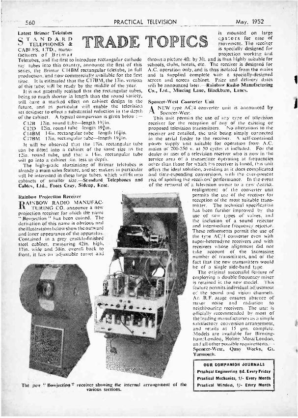
560
Latest Brimar Teletubes ST ANDA,RD
TELEPHONES & CABLES, LTD., manu- facturers of Brimar Teletubes, and the first to introduce rectangular cathode ray tubes into this country, announce the first of this series, the Brimar CI4BM rectangular teletube, in full production, "and now commercially available for the first time. It is estimated that the C17BM, the 17in. version of this tube; will be ready by the middle of the year.
It is not generally realised that the rectangular tubes, being so much shorter in length than the round variety, will have a marked effect on cabinet design in the future, and in particular will enable the television set designer to effect a substantial reduction in the depth of the cabinet. A typical comparison is given below :-
C12B 12in. round tube -length l9 in. C12D 12in. round tube -length lnin. C14BM 14in. rectangular tube -length 16in. CI7BM 17in. rectangular tube -length l9gin. It will be observed that the I7in. rectangular tube
can be fitted into a cabinet of the same size as the 12in. round tube, and that a loin. rectangular tube will go into a cabinet 3in. less in depth.
The high -grade aluminizing of Brimar teletubes is
already a main sales feature, and set makers in particular will be interested in these large tubes. which will fit into cabinets of smaller size.- Standard Telephones and Cables, Ltd., Foots Cray, Sidcup, Kent.
PRACTICAL TELEVISION May, 1952
RADE TOPll
Rainbow Projection Receiver RAINBOW RADIO MANUFAC-
TURING CO. announce a new projection receiver for which are name "Bowjection " has been coined. The derivation of this name is obvious and the illustrations below show the outward and inner appearance of the apparatus. Contained in a grey crackle- finished steel cabinet, measuring 42in. high, 17in. wide and 30in, overall back to front, it has an adjustable turret and
is mounted on large pastors for ease of movement. The receiver is specially designed for projection working and
throws a picture 4ft. by 3ft. and is thus highly suitable for schools, clubs, hotels, etc. The receiver is designed for A.C. operation only, and is thus isolated from the mains and is supplied complete with a specially- designed screen and screen cabinet. Price and delivery dates will be announced later. -Rainbow Radio Manufacturing Co., Ltd., Mincing Lane, Blackburn, Lancs.
Spencer -West Converter Unit ANEW type AC /4 converter unit is announced by
Spencer -West. This unit permits the use of any type of television
receiver for the reception of any of the existing or proposed television transmitters. No alterations to the receiver are entailed, the unit being simply connected in the aerial feeder to the receiver. A self- contained power supply unit suitable for operation from A.C. mains of 200 -250 v. at 50 cycles is included. For the dealer or user of a television receiver who is now in the service area of a transmitter operating at frequencies other than those for which his receiver is tuned, this unit offers the ideal solution, avoiding as it does complicated and time -expending conversions, with the ever- present risk of spoiling the receivers' performance. In the event of the removal of a television owner to a new district.
realignment of the converter unit permits the use of the receiver for reception of the most suitable trans- mitter. The technical specification has been further improved by the use of new types of valves, and the inclusion of a sound rejector and intermediate frequency rejector. These refinements permit the use of the type AC /4 converter even with super -heterodyne receivers and with receivers whose alignment did not take account of the increasing number of transmitters, and of the fact that the new transmitters would be of a single side -band type.
The original successful feature of employing a double-frequency mixer is retained in the new model. This feature permits individual adjustment of the sound and vision channels. An R.F. stage ensures absence of mixer noise and radiation to neighbouring receivers. The unit is officially recommended by most of the leading manufacturers as a simple satisfactory conversion arrangement, and retails at 15 gns. complete. Models are available for Birming- ham/London, Holme Moss/London, and all other possible requirements. - Spencer -West, Quay Works, Gt. Yarmouth.
The new Bowjection " receiver showing the internal arrangement of the various sections.
OUR COMPANION JOURNALS
Practical Engineering 6d. Every Friday
Practical Mechanics, 1/- Every Month
Practical Wireless, 1/- Every Month
May, 1952 PRACTICAL TELEVISION 561
The
Q 5
R
9
INDOOR TELEVISION AERIAL OF OUTSTANDING PERFORMANCE
INCORPORATING THESE EXCLUSIVE FEATURES * Greater gain ; reception at 25 -30 miles. * Highly directional properties. * Noise reduced by rotating aerial. * Attractively finished in cream enamel. * Can be mounted on set or in loft. * Fix it yourself ; no installation charges.
PRICE f3.3.O RICHARD MAURICE EQUIPMENT CO., PORTSMOUTH ROAD, COBHAM, SURREY
can SOLDER o
"VIEWMASTER TELEVISOR
you can have the thrill and satisfaction of building the
and what is more, save pounds by doing your own maintenance !
Up -to -date design. Appearance and performance as good as the com- mercial article. Backed by famous manufacturers. Designed by an expert, using STANDARD components. For gin. or 12in. Cathode Ray Tubes. Foolproof, stage -by -stage wiring instructions.
Send to
S
f Edgware Road , O The Component People
for Construction Envelope, which contains an explanation of T.V. reception, full -size working drawing of metal -work, 6 stage - by -stage building and wiring instruction sheets, price list of parts, etc. (State which station you wish to receive.)
Price 7/6 post free. Over 50,000 already sold !
We can supply any or all of the parts required, including aerial, cabinet, etc., and help you if in any difficulty.
H. L. SMITH & CO., LTD. 287/9 Edgware Road, London, W.2.
Tel : Paddington 5891. Hours 9 till 6 (Thursday I o'clock) Near Edgware Road Stations, Metropolitan and Bakerloo
SOLDERING tvíce as ifu-st
>I- mote .. *mote eevnom`caG
TYPE 51
Supplied complete with 25 feet reel of acid - cored solder, spare 25 feet resin - cored colder and fitted. with S feet tough rubber 3 -core cable. Finished in heavy chrome.
EACH REEL HOLDS 25 FEET CORED SOLDER
FEEDS AUTOMATICAL- LY WITH TRIGGER ACTION
PERFECT CONTROL FOR SMALL ASSEMBLY AND JOINTING WORK
FINELY BALANCED WITH EASY -GRIP PLASTIC HANDLE
RAPID, CONSTANT
HEAT
HEAT CONCENTRATED AT WORKING POINT
LOW CURRENT CONSUMPTION
d solder -
WoliSolderguni ole for all
inB Irons ava
work from fine instrument
to heavy industrial cutY
* Obtainable from all leading tool merchants and factors
WOLF ELECTRIC TOOLS LTD. PIONEER WORKS. HANGER LANE. LONDON. W.S.
VISIT STAND C 603, H.I.F. (CASTLE BROMWICH) MAY S -1G
562 PRACTICAL TELEVISION May, 1952
PREMIER RADIO CO. (REGD.) B. H. MORRIS & CO. (RADIO) LTD. ESTAB. 40 YEARS
This is our only address : (Dept. P.T.) 207, EDGWARE ROAD, LONDON, W.2 OPEN TILL 6 P.M. SATURDAYS Phones : AMBASSADOR 4033 & PADDINGTON 327112 TERMS OF BUSINESS : CASH WITH ORDER OR C.O.D. OVER El. Please add II- for Post Orders under 101 -,
116 under 401 -, unless otherwise stated.
BALANCED ARMATURE, LOW RESISTANCE HEADPHONES. Type 1. 541 pair. BALANCED ARMATURE. LOW RESISTANCE HEADPHONES. Type 2. 811 pair. HIGH RESISTANCE HEADPHONES, 12'6 pair. LIGHT -WEIGHT HIGH RESIST- ANCE HEADPHONES. 14,6 pair. BRAND NEW R1155 RECEIV -ERS. in original cases, complete with 10 valves. £12'10'0..7.6 Packing and Carriage. BATTERY CHARGER KITS. All incorporate metal rectifiers. Trans - forthers are suitable for 200:50 v. A.C. 50 cycle MAINS. Cat. No. 2002 Charges 6 volt accumulator
at t amp. Resistance sup- plied to charge 2 v. accu- mulator ... .. ... ... 21 2 6
2003 Charges 12 volt accumulator at 1 amp. ... £1 7 6
TUNING CONDENSERS. 4 -Gang, .0005 mid. Ceramic insulation. in f spindle. 5 -. 3- Gang. .0005 mfd.. f spindle, 716. GERMANIUM CRYSTAL DIODES, wire ends, midget size. The ideal Crystal Detector. G.E.C. or B.T.H. 4.6 each. METAL RECTIFIERS -FULL WAVE, 6 v. I amp.. 4i- : 12 v. 1 amp., 8r -. E.H.T. Pencil Type -Output : 650 v 1 mA., 4'7 each 1.000 v. t mA.. 61- each. BURGOYNE SOLDER GUNS, 75'-
CRYSTAL MICROPHONE An entirely insulated crystal microphone which can be safely used on A.C. /D.C. amplifiers. High impedance. No back- ground noise, really natural tone. The ideal Mike for tape, wire and disc record- ing and sound projectors. Price 22'6. MAINS NOISE ELIMINATOR KIT. Two specially designed chokes with three smoothing condensers, with circuit dia- gram. Cuts out all mains noise. Can be assembled inside existing receiver. &- complete. T.Y. WHITE RUBBER MASKS (COR- RECT ASPECT). We can supply a speci- ally designed White Rubber Mask for bin. C.R. tubes at 816 each. 9in. White Masks, 96. 121n. White Masks, 16 11. For Round or Flat faced Tube.
V.C.R. 97 C.R. TUBES We are once again able to offer this famous tube with the usual PREMIER guarantee of a full screen picture, free from cut-off. Every tube is tele- vision picture tested before despatch.
£2 S 0 Plus 5'- postage. paekina
and insurance.
NEW BABY ALARM KIT A tremendously improved and re- designed version of the famous Premier' Baby Alarm Kit, consisting of a Kit of Parts in Plastic Cabinet to construct a device to enable Baby's cries, or even breathing. to be heard in any selected room In the house. Consists of a 2 -valve amplifier (A.C. mains -operated 200,250 volts), with a Midget Telephone used as a Microphone. A 311n. Loudspeaker is now incorporated in the kit which together with other improvements in the design have resulted in tremendously improved sensitivity and quality of reproduction. May 10e left permanently connected. Extra Micro- phones In different rooms may be used without impairing the efficiency of the Unit. The lead from Microphone to the Unit may be up to 60 ft. in length. Complete with Valves. Circuit and Instructions. 69'6. Already built and tested, 79'6, plus 2/6 pkgiearr. PREMIER SUPERIIET COILS. 16-50, 180 -550, 800 -2,000 metres. Set, with circuit. 1016. EX- U.S.A, U.H.F. AERIAL, with untuned detector stage consisting of VR92 valve, etc. Brand new in carton, 5' -. H.T. ELIMINATOR AND TRICKLE CHARGER KIT. All parts to construct an eliminator to give an output of 120 volts at 20 niA., and 2 volts to charge an accumulator. Uses metal rectifier, £2.
IMPORTANT ANNOUNCEMENT : We cannot accept responsibility for, or guarantee, any kit or component sold as a Premier product by firms other than ourselves. All prices quoted are those ruling at the time of submitting
advertisement copy, and are subject to alteration without notice.
FIRST -CLASS TELEVISION and RADIO COURSES . .
GET A CERTIFICATE I After brief, intensely interesting study -undertaken at home in your spare time -YOU can secure your pro- fessional qualification or learn Servicing and Theory. Let us show you how !
----FREE GUIDE The New Free Guide contains 132 pages of information of the greatest
'Importance to those seeking such success compelling qualifications as A.M.Brit.1.R.E., City and Guilds Final Radio, P.M.G. Radio Amateurs' Exams., Gen. Cert. of Educ., London B.Sc. (Eng.), A . M . I . P . E . , A.M.I.Mech.E., Draughtsmanship (all branches). etc., together with particulars of our remarkable Guarantee of
SUCCESS OR NO FEE Write now for your copy of this invaluable publication. It may well prove to be the turning point in your
career. FOUNDED 1885 -OVER
..... _ 150,000 SUCCESSES NATIONAL INSTITUTE OF
ENGINEERING (Dept. 462), 148, HOLBORN,
LONDON, E.C.I.
The " Fluxite Quinn " at Work "Our T.V. light's almost done.
So i borrowed your headlamp old son.
With the aid of FLU XITE It's a much better light.
Let's see if the Arsenal's won."
See that FLUXITE is always by you -in the house -garage- workshop- wherever speedy soldering is needed. Used for over 40 years in Govern- ment works and by leading engineers and manufacturers. Of all ironmongers -in tins, from 1/- upwards. The FLUXITE GUN puts FLUXITE where you want It by a simple pressure. Price 2 /6, or filled 3/6.
FLUXITE SIMPLIFIES ALL SOLDERING
Write for Book on the Art of " SOFT Soldering and for Leaflets on CASE- HARDENING STEEL and TEMPERING TOOLS with FLUXITE. Price lld,each.
FLUXITE Ltd., Dept. P.T. Bermondsey Street, London, S.E.1
THE MODERN BOOK CO. Television Principles and Practice,
by F. J. Camm. Price 25s. Od., post- age 9d.
Radio Amateur's Handbook, by A. R. R. L. 1952 edition. Price 30.s. 0(1., postage 1s. Od.
Television Receiver Practice. by R Holland. Price 5s. Od., postage 3d.
Cathode -Ray Oscillographs, by J. II. Reyner. Price 15s. Od., postage 6d.
Inexpensive Television for the Home Constructor. Price 2s. 6d., postage 2d.
The De Luxe Ifome Built Televisor and Radiogram. Price 6s. 6d., postage 4d.
Television Explained, by W. E. Miller. Price 5s. Od., postage 4d.
Television Receiving Equipment. by W. T. Cocking. Price 18s. Od., postage 63.
Feedback, by N. H. Crowhurst. Price 3s. 6d., postage 3d.
Sound Reproduction, by G. A. Briggs. Price 10s. 6d., postage 6d.
Foundations of Wireless, by M. G. Scroggie. Price 12s. $d., postage 6d.
Encyclopedia on Cathode -Ray Oscil- loscopes, by Rider and Uslan. Price 75s. Od., postage Is. Od.
Magnetic Recording, by S. J. Begun Price 25s. Od.. postage 9d.
Radio Valve Data, compiled by ' Wire- less World.' Price 3s. 6d., postage 3d.
P. H. Brans' 'ade- Mecum, 1952. Price 25s. Od., postage 9d.
We have tfie finest selection of British and' American books in the Country. Complete list on application. _
19 -23, PRAED STREET, (Dept. T.5) LONDON, W.2
l'ADdington 4183.
'
r
TELEVISION TIMES 563
British Radio Exports Still Rising IN spite of the demands of the
defence programme, British radio exports in February again showed an increase, the total value being £2,136,000, which, with the January figures, brings the annual rate to more than £25 million compared with £22 million in 1951.
All four sections of the industry show a substantial increase in January and February compared with the first two months of 1951, the comparative figures, based on Customs and Excise returns, being :
1951 - £2,804,000 ; and 1952- £4,293,000.
These figures take no account of indirect exports of equipment in- stalled in ships and aircraft or components used in electrical appa- ratus other than radio and elec- tronic equipment. Half the output of components, it is estimated, is being exported.
H.M.V. 21in. Tube Direct Vision Receiver HIGHLIGHT of the 1952 Ideal
Home Exhibition was the largest direct screen picture, pro- duced on H.M.V. stand.
Special techniques have enabled a metal 21ín. Emiscope tube to be developed for use in this model. This tube has an exceptionally wide neck angle which means that a much bigger diameter screen can be obtained without an excessive tube length. it has the special aluminised screen pioneered by E.M.I. in this country and provides pictures of outstanding merit, suitable for day- light viewing.
A special circuit innovation enables the picture quality to be maintained even under fringe area conditions, and the receiver is tunable to all existing or projected BBC television stations. Provisional price, 275 guineas, tax paid.
- Television Afloat SCOTTISH householders are
now able to see continuous television, and ships entering the Clyde may have a television set installed on board when they come into dock.
The Editor will be pleased to con- sider articles of a practical nature suitable for publication in " Practical Television." Such articles should be written on one side of the paper only, and should contain the name and address of the sender. Whilst the Editor does not hold himself respons- ible for manuscripts, every effort will be made to return them it a stamped and addressed envelope is enclosed. All correspondence intended for the Editor should be addressed to : The Editor, "Practical Television," George Newnes, Ltd., Tower House, Southampton Street, Strand, W.C.2.
Owing to the rapid progress in the design of wireless apparatus and to our efforts to keep our readers in touch with the latest developments, we give no warranty that apparatus described in our columns is not the subject of letters patent.
Copyright in all drawings, photo- graphs and articles published in
Practical Television " is specifically reserved - throughout the countries signatory to the Berne Convention and the U.S.A. Reproductions or imitations of any of these are Therefore expressly forbidden.
These sets, made by Pye, can be rented by the day for a few shillings as an extension of the service already established on the Thames and Mersey by Rees Mace (Marine), Ltd., a subsidiary of Pye.
The service is greatly appreciated by ships' companies, for television sets cannot normally be hired except on a long -term basis with,. in many cases, a wait of three months before the set is installed.
Television Licence Increase APPROXIMATELY 12,687,000
broadcast receiving licences, including 1,386,000 for television, were current in Great Britain and Northern Ireland at the end of February, 1952. For the second month in succession the number of television licences has increased by more than 100,000.
Motorists are reminded that they need a separate broadcast receiving licence for a wireless set fitted in a car.
Wenvoe on Low Power IT is announced that when the
Wenvoe (Channel 5) station opens -probably in August -it will be on low power for the first period of working, in the same manner as
with Kirk o' Shoats. The temporary transmitter will be rated at 5 watts, and therefore any early experiments which readers carry out -should be carefully noted as they may prove misleading when the full power is used on the station.
N.E. Disappointment DEALERS and prospective viewers
in the North East were " keenly disappointed " recently that the P.M.G. gave no concrete promise of an early resumption of work on the Pontop Pike transmitter. He stated that the conditions were not ripe for work to be resumed but that the position would be kept in mind. Shortage of materials and labour were such that no indication could be given as to any possible date.
Boat Race Controlled by R. -T. THE boat race was controlled by
VHF radio -telephone from two Port of London Authority vessels.
Especially equipped with Pye PTC 113, the Nore and the Ranelagh were under the super- vision of River Superintendent and Chief Harbourmaster, Commander Coleman, R.N. (retd.). The Rane - lagh was ahead of the two crews keeping the course clear of obstruc- tions, while the Nore was Mime diately astern- of the race. These' two boats were in -constant touch with each other over the radio- telephone.
Pye . Radio Telecommunications' provide all the V.H.F. for the Port - of London Authority vessels as well as for the P.L.A. Police.
Interference with Wireless Telegraphy
THE Postmaster -General has appointed a third Advisory
Committee of twenty -one members from a panel nominated by the President of the Institution of Electrical Engineers, with the appro- val of the Council, to consider the requirements which might be pre - scribed in regulations dealing wit't interference with wireless telegraphy caused by small electric motors.
The members of the Committee are :
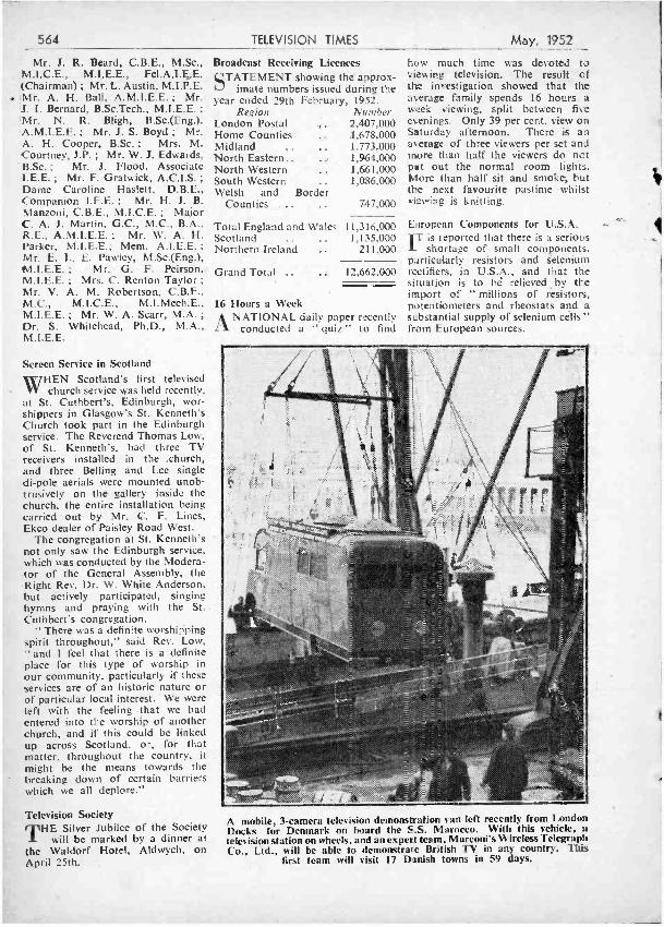
564
Mr. J. R. Beard, C.B.E., M.Sc., M.I.C.E., M.1.E.E., Fe1.A.I.E,E. (Chairman) ; Mr. L. Austin, M.I.P.E. iMr. A. H. Ball, A.M.I.E.E. ; Mr. J. I. Bernard, B.Sc.Tech., M.I.E.E. ;
Mr. N. R. Bligh, B.Sc.(Eng.), A.M.I.E.E. ; Mr. J. S. Boyd ; Mr. A. H. Cooper, B.Sc. ; Mrs. M. Courtney, J.P. ; Mr. W. J. Edwards,
' B.Sc. ; Mr. J. Flood, Associate LE.E. ; Mr. F. Gratwick, A.C.I.S. ;
Dame Caroline Haslett, D.B.E., Companion I.E.E. ; Mr. H. J. B. Manzoni, C.B.E., M.I.C.E. ; Major C. A. J. Martin, G.C., M.C., B.A., R.E., A.M.I.E.E. ; Mr. W. A. H. Parker, M.I.E.E.; Mem. A.I.E.E. ;
Mr. E. L. E. Pawley; M.Sc.(Eng.), tN.1.E.E. ; Mr. G. F. Peirson, M.I.E.E. ; Mrs. C. Renton Taylor ;
Mr. V. A. M. Robertson, C.B.E.. M.C., M.I.C.E., M.I.Mech.E., M.I.E.E. ; Mr. W. A. Scarr, M.A. ;
Dr. S. Whitehead, Ph.D., M.A., M.I. E. E.
TELEVISION TIMES May, 1952
Screen Service in Scotland WHEN Scotland's first televised W church service was held recently,
at St. Cuthbert's, Edinburgh, wor- shippers in Glasgow's St. Kenneth's Church took part in the Edinburgh service. The Reverend Thomas Low, of St. Kenneth's, had three TV receivers installed in the .church, and three Belling and Lee single di -pole aerials were mounted unob- trusively on the gallery inside the church, the entire installation being carried out by Mr. C. F. Lines, Ekco dealer of Paisley Road West.
The congregation at St. Kenneth's not only saw the Edinburgh service, which was conducted by the Modera- tor of the General Assembly, the Right Rev. Dr. W. White Anderson. but actively participated, singing hymns and praying with the St. Cuthbert's congregation.
"There was a definite worshipping spirit throughout," said Rev. Low, " and I feel that there is a definite place for this type of worship in our community, particularly if these services are of an historic nature or of particular local interest. We were left with the feeling that we had entered into the worship of another church,, and if this could be linked up across Scotland, or, for that matter, throughout the country, it might be the means towards the breaking down of certain barriers which we all deplore."
Television Society THE Silver Jubilee of the Society
will be marked by a dinner at the Waldorf Hotel, Aldwych. on April 25th.
Broadcast Receiving Licences STATEMENT showing the approx-
imate numbers issued during the year ended 29th February, 1952.
Region Number London Postal 2,407,000 Home Counties 1,678,000 Midland .. 1,773,000 North Eastern.. .. 1,964,000 North Western 1,661,000 South Western 1,086,000 Welsh and Border
Counties .. 747,000
Total England and Wales 11,316,000 Scotland .. 1,135,000 Northern Ireland .. 211,000
Grand Total .. .. 12,662.000
16 Hours a Week ANATIONAL daily paper recently
conducted a " quiz " to find
how much time was devoted to viev.ing television. The result of tlw investigation showed that the average family spends 16 hours a week viewing, split between five evenings. Only 39 per cent. view on Saturday afternoon. There is an average of three viewers per set and more than half the viewers do not pat out the normal room lights. Nitore than half sit and smoke, but the next favourite pastime whilst viewing is knitting.
European Components for U.S.A. IT is reported that there is a serious
shortage of small components, particularly resistors and Selenium rectifiers, in U.S.A., and that the situation is to bé relieved by the import of " millions of resistors, potentiometers and rheostats and a substantial supply of selenium cells" from European sources.
A mobile, 3- camera television demonstration van left recently from London Docks for Denmark on board the S.S. Marocco. With this vehicle, a television station on wheels, and an expert team, Marconi's Wireless Telegraph Co., Ltd., will be able to demonstrate British TV in any country. This
first team will visit 17 Danish towns in 59 days.
May, 1952 PRACTICAL TELEVISION 565
TALLON CABINETS
for the
VIEW MASTER ELECTRONIC ENGINEERING & PRACTICAL TELEVISION SETS MINI-FOUR ARGUS
In pack-flat kits or assembled cabinets. Radiogram, Radio and Television or combination cabinets made to suit customer's requirements, in quantities or singly. Tape Recorder Cabinets.
Prices and literature on application
JAMES TALLON & SONS LTD. (Dept. P.T.I.)
MANOR WORKS MANOR ROAD RUGBY
Telephone : RUGBY 2070
" YOU CAN RELY ON US,' FOR CLEAN COMPONENTS AT COMPETITIVE PRICES
48 HR. SERVICE AGAIN VALVE DATA MANUALS
MULLARD 5/-.
CIC ... ... CV1141 ... 1)1(63 ... EA50 ... ... KTZ41 ... ... EF39 ... ... EF50 ... ... EF54 ... ... 31)6 ... EL32 ... EI,35 .... ... KTW61 ... ... KT33C .... MS/Pen
...
N37 ... ... Pen46 ... PT25H ... 078 ... ... VU1.20A ... 1Q4 ... ... 1S4 ... ... 3A4 ... ... 3Q5gt ... ... 354 ... ...
MARCONI ()SRAM,
VALVES I3RIMAR,
10/-
3/6 7/6
10/6 7/6 7/6
101 8/6
16/-
10/6
10/- 4/6 8/6
10/6 7/6 8/6
10/6
5Z:3 ... 12AT7 ... 6AC5 ... 6AK6 ... 638 ... 604 ... 6C5M ... 6C5gt ... 686m ... 6J5gt ... 637G ... 6E6 ... 6E7 metal 6K7G ... 61.7 metal 6SA7gt 6SH7 metal 126E7 ... 12A6 .. 12.SC7 ... 12807 ... 125E7 ... 12SR7 ... 76 ...
... 10.6
... 106
...
...
...
:::
..,
... 7
... 7
...
...
...
...
... 63
...
77
98 VU111 ... 3285 ... 35Z4gt ...
'- 6K8gt ...
'8 Ng ::: - KT41 ... 6 KT63 ... - KT66 ... -
6 6AC7M ... - 6BW6 ...
6 6AT6 ... 6 5005 ...
7 - S130 ... 7 - 121(8 ... 6'- 705 ... 8 - UB41 ...
VR116 ... 6'- IW41350
... 7.6
... 7 6
... 12 6
... 1243
... 12/6
::: igig ... 10/6 ... 10/6 ... 12/6
... 843
... 151-
... 10/6
... 13/6 7/6
... 6/- .. 8/6
... 816
... 3/6
Postage 6d. any quantity, Thousands of valves in stock including many BVA types at List Price. Let us know your requirements and we will quote the price. SWITCHES.-Rotary : 4 pole, 4 way, 36. 4 pole, 3 way, 4. - 3 pole, 4 way, 4/.. 2 pole, 6 way. 4 -. 6 pole, 3 way, 4/6. SELENIUM RECTIFIERS.-36EHT50, 22/6. 36EHT45, 20 6. Type 14D36. 10/6. Type 14A86, 18/8. Type 36EHT103, 27:10. WX3. 35. WX6. 35. 12v. 5 m a.. 1/-. 36EHT40, 20/61.1. EASY BUILT cliASSIS.-Two chassis for the Easybuilt Tele- visor, heavy gauge tinplate soldered four sides. 8/6 each. EF50 Sin. x 3m. screens, 8d. Ask or complete list of parts. SPEAKERS.-211n. WB. 17,3. 6in. Elec, 15/-. 31in. Elac, 14 3. 5in. Plessey. 14i9. tin. P.M. 15;-. Plessey 51n. M.E., 1,000 field, 15/-. Plessey 101n., 21/-. HAINES COMPONENTS.-Scanning Coil Units. Type S914, S27. 45/- S91411, S112, each. 42-. Transformer TQ135, 1716. Choko Type LUMP', LUS6L. 18.6. TQ132. 121, TK10/41, 38/-. Kit Coil Cans. Formers and Wire. 17.8 set of 10. SPNNERS.-4 B.A., 8.1. Five for Box type, set of three Flat Type, 2 RA., 4 B.A., 6 B.A., 1/-. FILAMENT TRANSFORMERS.-Midget dimensions, finished in green crackle. Primary 210,240 v. to 03v. 1.5 a.,316 ; to 6.3 v. 3 a..
566 PRACTICAL TELEVISION May, 1952
U.E.I. CORPN., THE " ARGUS " T'ELEVISOR The following items available ex -stock :
MAINS TRANSFORMER 425- 0 -425v. 200ma., 6.3v. 4a.. 6.3v. 4a., 5v. 3a. (postage 1/6) E.H.T. TRANSFORMER FOR VCR 97 TUBE
5001r. 5ma., 2 -0-2v. 1.1a., 2 -0 -2v. 2a. (post 16) ... ... ... ... ... s'CR 97 TUBE Tested full screen for T.V.. with base (carriage paid) ... ,. CHOKE 5h. 230ma. (postage 1 / -) VALVES EF50 (VR91) ... ... ... 5114G ... ... ... ..
EB34(VR54i ... ... ... ... EF36 (VR56) ... ... ... SP61 (VR65) .. ... EA59(VR92) ... ... ... ... POTENT IIWI ET ERS Les. switch ... ... ... ... With switch ... ... ... VALVE IIOLDERS I.0. or M.O. ... .. ß9G ... ... ... ... Diode ... ... RESISTORS
2w. ...
... ... ... 15w. 2:5k. .. ... CONDENSERS Mica and Silver Mica ... Tubular, - .l mfd. ... . ... ... ...
. 9d. 9d.
.Ol m f d . ... ... ... ... ..
.05mf1 ... ... ... ...
ELECTROLY FIGS 8mfd. 450v. ... 8 x 8mfd. 450v. . 16 x 16 mfd. 450v. 25mfd. 25v. ... 50mfd. 12v. ... TRLMMERS 0 -3Opf. COIL FORMERS WITH SLUGS
37/8 Yin. 8d. fin. .. .. 10d. P.M. SPEAKERS (less transformer) 5in. Plessey 12'6
Plessey .. k716 6'- (Postage 1'6 per spp eaker)
PENTODE OUTPUT TRANS-
THE RADIO CORNER, 138, Gray's Inn Road, London. W.C.I (Phone TERminus 7937)
2'6 49 7-
... 1/6
7d.
451-
6'6
126 7'6
36
46 6d.
10d. 6d.
5'- ItDF 1 RECEIVER The unit reviewed in the October and November issues of this journal for conversion into a Televisor giving SOUND AND VISION ON THE ONE CHASSIS. Complete with 14 valves as follows : 5 of SP61. 2 of P61, 3 of EA50, and 1 each CV63. EBM, EC52, 5Z40. also a complete reprint of the above review (carriage, etc., 51 -) ... ... ONLY 49'8 194 I.F. STRIP Reviewed in the October issue of
4i. this journal. An easily modified 5d. I.F. Strip recommended for TV 6d. constructors who want good re- Od, sults at moderate costs, or for those 2,. who have built televisors but are
having trouble in the Vision or 6d. Sound receivers. Can be built into
any layout, measuring 181n. x 5ín. x 5in. Complete with valves as follows : 6 of SP61, 1 of EA50, and 1 of EF36 or EF39 (carriage. etc., 2(6) ... ... ... ONLY '45/-
.5mfd.
.03mfd. 2.5kv.
.1 mfd. 3k v. (block type only)
... 9d.
... 9d.
... 2 - MAGNIFYING LENS FOR VCR97
... 2'6 TUBE First grade oil filled (post-
... 4'6 age. 2 -) ... ... ... ONLY 25'-
TRANSFORMERS Manufactured to our specifications and , fully guaranteed. Normal Primaries. 425v. -0-425v. 200ma., 6.3v. 6a.. 6.3v. 6a., 6v. 3a., 0- 2- 4-6.3v. 3a. ONLY 7218 350.- 0- 350V.180ma., 6.3v. 6a., 6.3v. 3a., 5v. 3a. ... ONLY 4216 250v.- 0 -250v. 100ma., 6.3v. 6a.. 5v. 3a. ... ONLY 32/6 All above are fully shrouded, up- right mounting. Top shrouded, drop through :
260v. -0-260v. 70ma., 6.3v. 3a., 5v. 2a. ONLY 16.8
Universal Mounting: 350v. -0-350v. 80ma., 0- 4 -6.3v. 4a., and 0 -4 -5v. 2a.
ONLY 18'6 5.5 kV. E.H.T. with 2 windings of 2v. la. .. ONLY 72,6 7 kV. E.H.T. with 4v. la. ONLY 82,6 PLEASE ADD 1/6 POSTAGE FOR EACH TRANSFORMER. CHOKES 20h. 80- 120ma. .. ... 9'6 10h. 100- 150ma. (post, ea. choke 1;-).- 12,6 10 VALVE 1Y METRE RECEIVER .
ZC8931 For long- distance TV results. Valve line -up is 6 of SP61, 2 of EA50. and 1 each EF54 and EC52, and the 12 Mc /s 6 -stage I.F. Strip gives tremendous amplification with ample bandwidth of 4 Mcrs. EASILY MODIFIED, full details being supplied (carriage. etc., 5,' -) ONLY 59.'8 RECEIVER R3118 An A.C. Mains operated version of the above ZC8931, but is infinitely more powerful, having another I.F. Stage and employing 16 valves 6 of SP61. 4 of EA5O, 2 of EF54, and 1 each EC52, P61. 5Z4 and Y63
Magic Eye." Built -in power pack operates from 180 -240v. A.C. In excellent condition (carriage. etc., 7,6) ... .., ,,. ... ONLY 9716
Cash with order, please, and print name and address clearly. Open until 1 p.m. Saturdays, we are 2 mins. from High Holborn (Chancery Lane Station), 5 mins. by bus from King's Cross
OPPORTUNITIES IN I Pre- Amplifier Tra 200,250 v., Sec. 2 6.3 v. at 1.5/2 amp HS150. 350 -0 -35 6.3 v. 3 amps. C Half -shrouded, 30/ FS43. 425 -0 -425
May, 1952 PRACTICAL TELEVISION '567.
UNDEI/NIfA lilA WHILEWHILE politicians and the general
argue about the merits or demerits of sponsored television, there has been a steady increase in the number of examples of "unsponsored" advertising both on TV and ordinary radio. The mention of the theatrical shows or films in which a TV artiste is currently appearing is regarded with much favour by the artistes' agents and publicity men. " It's equal to an expensive double- column advert in a national newspaper," said one prominent publicity man recently, adding, " and it's all bunce -it costs nothing !" Then there is the adver- tising value of proprietary goods being seen, more or less inconspicu- ously, on the TV screen as part of the props or settings of a play or docu- mentary feature. A classic example was recently seen in a documentary feature dealing with the progress and design of shaving implements, con- cluding with a close -up of a certain make of electric razor. This close -up of the razor brought forth a number of complaints from viewers with strong objections to sponsored pro- grammes ! But newspaper compe- titions and awards for the best television or radio features (culmin- ating in a " grand concert and presentation of awards ") undoubt- edly bring kudos and glory upon the eiterprising newspaper - without offending any viewers. And the television feature, Current Release, is nothing more or less than the presentation of trailers of new films being released to the cinemas. In actual fact, short excerpts are shown, which usually prove to be much more interesting and appetising than the usual film trailer with its fusillade of adjectives and mumbo jumbo of dis- connected scenes. I am not aware of anyone objecting to this mild type of advertising. It is evident that there is a very fine dividing line between the acceptable and the objectionable in TV advertising, a borderline as intangible as that between sanity and insanity:
"CURRENT RELEASE " IHAVE noticed that the sound
quality of the films shown in the Current Release is definitely of a lower order than either the direct BBC studio sound or some of the be BBC newsreel and documentary film recordings. It is probable that
REFLECT/ON,S
THE DIPOLE
By Iconos the latter were made using magnetic recording, which is not subject to the many sources of distortion to which photographic recording is subject. An additional factor is that films for reproduction at big volume in large auditoria are naturally subjected to bass cut in recordings which is not required for recordings to be repro- duced on loudspeakers in small rooms. Another point about these Current Release film extracts is that all types of film are shown, drawn from films with censor certificates in the " U," " A " or " X " categories. Apparently, it is an offence to allow children to see an " X " film or even a trailer for an " X " film in a cinema. Nor can the cinema manager advertise or announce the film without mentioning the class of censor's certificate it carries. The BBC, however, can show all or part of an " X " film without breaking the aw.
PROBLEMS FOR THE POLITICIANS
THE politicians will have to make
up their minds quickly about
this matter of sponsored television. While it is reported that Sir David Maxwell -Fyfe, the Home Secretary, and Earl de la Warr, the Postmaster - General, are not yet convinced that sponsored television is desirable,there is no doubt that the majority of Conservative M.P.s would favour the experimental introduction of a limited amount of sponsored television on the existing BBC programmes. Further- more, they would support the allocation of a special transmission frequency for commercial use, in connection with big -screen television. The Odeon Theatre, Leicester Square, is already wired for big- screen TV, and experimental transmissions have also been made at one or two suburban cinemas and halls. A theatre in the Golders Green district is to be fitted out shortly with the very latest big -screen equipment. But nothing is likely to happen until the new BBC Charter comes into operation in June.
USES OF BIG -SCREEN TV DIG-SCREEN TV is a field in which
Britain holds the lead. Cintel's newest equipment gives a reflected light value from their screen of about 8ft. lamberts compared with the American average of about 2ft. lamberts. Higher light intensities are obtainable by making use of the intermediate film system, in which the picture is received and photo-
PROFESSOR BOFFIN
" The Boffin Black Screen indeed ! Everybody looks like a Kentucky Minstrel."
568
graphed on film, which is developed at a high speed and projected. That is the system used in America by Paramount. Intermediate film systems are not favoured here. Big - screen TV in Britain has largely been confined to closed- circuit demon- strations of various kinds. I hear that the World Dental Congress, to be held at the South Bank Festival Hall in July, may be utilising big -screen TV for demonstrating various special dental techniques and operations to a
large audience. Normally, of course, only two or three persons could see the details of dental surgery which, with big- screen TV, can be readily shown to a thousand students at one time.
THE BBC " BEASTS " WAS sorry to see What's My Line
go out of circulation, and the departure of Picture Page leaves a gap. Billy Bunter of Greyfriars School ends just as it was getting into its stride. But most of these
PRACTICAL TELEVISION May, 1952
series programmes deserve a revival, after a few month's rest. There are lots more adventures of both Billy Bunter and Sherlock Holmes to justify regular annual " seasons " of these classic figures of popular literature. If the BBC decide against reviving these series playlets, then I
will have to borrow Bunter's famous epithet and call them " Beasts ! "
VIEWING COURSE THE recent production of Frederick
Knott's "Dial M" for Murder was a successful " thriller " for TV's Sunday Night Theatre. Providing a " viewing course " on " How to Kill the Wife," the author's involved plot was put over so well by Emrys Jones and Raymond Huntley that until the last few minutes it seemed the erring husband would get away with it. Julian Amyes's skilful direction, and dialogue good enough to dispense with the familiar " who dun it " clichés, overcame the obstacle of the far -fetched script.
CREDIT TITLES
ONCE more, W. Somerset
Maugham confirmed his title to be the premier writer for television in Home and Beauty. This play, written many years ago, was by no means a period -piece and once again witty dialogue carried the day. Barbara Murray and Barry K. Barnes proved themselves to be thoroughly at home with television technique. and all the production values were first class. The technical qualities of this production matched up to the excellent directorial touches. Inc - dentally, I note that the BBC play department are beginning to strike a new note by crediting TV plays to a producer and also a director. Let us hope that this does not ultimately land us with those interminable credit titles, mentioning assistants. cameramen, hairdressers and dubbing crews, which confront us at the cinema. BBC policy in this matter should be firm before the rot sets in.
The Oxford and Cambridge Boat Race
o VSaturday, March 29, the BBC again televised and broadcast a commentary on the Oxford
and Cambridge Boat Race. The broadcasts were both subject to bad interference.
The sound commentary was made from the launch " Consuta." The equipment in the launch included the normal microphone and amplifiers, together with
two frequency -modulated radio transmitters, operating in the high- frequency band. One transmitter was used for the commentary and the other. in conjunction with a
receiver, for cueing and intercommunication. The receiv-
ing point for the transmissions from the " Consuta " was situated on the roof of Harrods Depository, and from there the sound commentary was fed to Broad - casting House over lines provided by the Post Office.
Two Cameras For setting the scene and televising the start of the
race, two shore based cameras were used, one on the roof of the Star and Garter Hotel, near Putney Bridge,
and another on one of the adjacent boat -houses. In
addition, two complete camera channels were installed in the launch " Everest." This is a larger and more
modern craft than hitherto used and formed the main
production point for the broadcast. It is equipped with
a spacious cabin which permitted a much more satis-
factory layout of the television equipment, whilst at the same time affording it protection from possible inclement
weather. In addition to the cameras and ancilliary apparatus,
the "Everest" carried a vision transmitter, two radio vision monitors, a sound transmitter and receiver and an intercommunication radio telephone for control purposes. Power for operating this equipment was
obtained from a mobile petrol- driven alternator carried on the launch. Three shore receiving points were estab-
lished at Putney, Riverside Telephone Exchange, and
Mortlake. The vision signals received from the launch were passed by Post Office vision cable from Putney and Riverside Exchange to Olympia, where a switching centre remotely controlled from Broadcasting House, connected either point to Broadcasting House and Alexandra Palace. Snow and water caused a break- down in one of the camera channels.
Centimetric Link The vision programme from the launch received at
Mortlake was passed by centimetric wave radio link to Riverside Exchange and thence by Post Office vision cable via the Olympia switching centre to Broadcasting House and Alexandra Palace. At the three shore stations provision was also made to handle the sound accompani- ment to the vision programme. From the receiving points it was passed over Post Office lines to Broadcasting House and Alexandra Palace.
The cameras used for this broadcast were the Image Orthicon type, made by Marconi's Wireless Telegraph Co. The vision and sound transmitters and receivers in the launch were supplied by Pye, Ltd., whilst the intercommunication radio telephone equipment was
of Mullard manufacture. For the centimetric wave
radio link between Mortlake and Riverside Exchange Marconi apparatus was used.
NEW EDITION NOW READY
53 PRACTICAL WIRELESS" CIRCUITS 15th Edition
6/ -, or 6/6 by post from
GEORGE NEWNES LTD., Tower House, Southampton Street, Strand, W.C._
May, 1952 PRACTICAL TELEVISION
PERSONNEL RADIO CABINETS Correct di-
, mensions to take P.W."Mini
. íi`.:ä - Four" and similar midget su- perhet or
F. In- terna1 di- mensions Clin. high x 5lin.wide x Sin. deep. 'With spec- ial plastic grained
finish. Price, 15 %9, plus 1 6 postage and packing. De luxe model dovered with brown crocodile leathercloth and banded with grey lizard leathercloth as illustrated. Price. 22í3, plus 1,6 postage and packing.
RADIO CHE1I I('A LS CLEAR ('FIENT
Almost instantaneous drying for coil winding and all repairs, 18 per tube. " F:N tNIACLEAN." For safely removing the en- unel off the finest wires. 2 - per tube.
ALUMINIUM TUBE Ideal for making T.V. aerials, etc., 18 ft. -
Orders are dealt with by our Ruislip depot. To avoid delay address to : E.P.E., Ltd. (Dept. 51 Windmill Hill,
V R O, Ruislip, Middx. In- clude extra 2'6 un-
J der £2, 1;5 under £l,
P I , R E C U S IO N E O UAPMf N T
MAGNETIC T.Y. TUBES 9in. G.E.C. Flat Ended,
Heater 6.3 v.
From 551-
These tubes have had very little use and will probably give years of service. TYPE 1. Have no faults whatsoever and have only had the smallest use. Price £5 15'- each.
TYPE 2. Have small ion burns otherwise in good condition. Price £3115,- each. TYPE 3. Have large ion burns but are useful as spare or when first testing out a circuit, or doing repairs, etc. Price £2,15/ - each. NOTE Callers to our Ruislip branch can see these tubes demonstrated but whether you see it or not we guarantee a " working " tube. If not calling please add 7'6 each tube for packing and postage.
T.Y. SIGNAL TRACER
By tapping the test prod on the grids and anodes of both vision and sound receiving valves. Signals can be traced through the set to the tube and loudspeaker, res- pectively. similarly on the sync. separ- ator and time base valves one can get a powerful indication of the sync. pulses and blocking oscillator pul.:es. There is, in fart, no limit to the number of uses to which this Signa Tracer can be put. 5 valve, on all metal chassis, all mains working complete with 8in, loudspeaker and instructions Price £670' -. plus 76 postage and insurance.
P.T. ARGUS Complete set of valves as specified all tested before des- patch and guaranteed to be in perfect working order. Price, £5x11 -, Post and insurance 2,6.
569
ELPREQ WOLSEY 5 VALVE AC/DC SUPERHEr
Long, medium and short wave in handsome wooden cabinet, illu- minated glass dial with station names, A.V.C. and usuairefine- ments : Size llin. x 51ín. x 7in, with B.V.A. valves and built -in aerial. 12 months' guarantee. Limited quantity only. £9'5 -or £3/2,6 deposit and balance over 10 months, carriage and in- surance 5/ -.
BLANK CHASSIS
18 S.W.G. Aluminium 7 x 31 x 2 ... 5/-
91x41e2i ... 5.'9 10x8x21 ... 7'- 10x5,x21 ... 6'6 10x9 x3 .. 7 3 12x9 x21 ... 7 3 14 x9 x21 ...76 14x10x3 ... 8 -
16x10x3 ... 83 16x8x3 ... 8- 111x10x3 ... 78 16xMx3 ... 88 19Ix9x21 ... 9B 20x10x3 211x9 x21108
152 -153 FLEET STREET, E.C.4, and at WINDMILL HILL, RUISLIP MANOR, MIDDX.
Come to the CLASSIC for
"THE CLASSIC SERVICE " Our Motto is
" NOTHING 15 TOO MUCH TROUBLE"
We will ship to any part of the British Isles or Abroad.
TAPE RECORDING EQUIPMENT Agents for all leading makes,
AMPLIFIERS& HI -Fl EQUIPMENT Agents for : Leak, Quad, Williamson, Decca, Connoisseur, etc.
TELEVISION COMPONENTS Northern and Scottish readers write to as for details of our special offer of View Master components. Full details sent by return. Special terms available for those wishing to build their own Television receivers. Maximum stocks of valves, tubes and other accessories available for des- patch by return.
Send 211,,d. stamp for List, to :
The Classic Electrical Co. Ltd.
352 -364 LOWER ADDISCOMBE RD., CROYDON, SURREY.
Tel.: ADD. 6061 -2
When you ore planning to use
ALUMINIUM, LIGHT ALLOYS, BRASS, COPPER, BRONZE,
remember , you have a choice of 3,000 stock sizes of
TUBE, ROD, BAR, SHEET, STRIP, WIRE, ANGLE, CHANNEL, TEE
at
H. ROLLET & CO. LTD. 6, CHESHAM PLACE, LONDON, S.W. I
Phone : SLOane 3463 WORKS :
32136, ROSEBERY AVENUE, LONDON, E.C.I.
KIRKBY TRADING ESTATE LIVERPOOL
" No Quantity too Small "
TELEVISION COMPONENTS
FOR T111,,
" Practical Wireless" VIEWMASTER AND E. E. TELEVISORS
IN STOCK
Price lists of specified and alternative components available on request.
Prompt Postal Service
J. T. FILMER MAYPOLE ESTATE, BEXLEY, KENT
TEL. Bexleyheath 7267
ELEMENTARY MATHEMATICS
by LEWIS W. PHILLIPS, M.I.E.E., F.Inst.P.
Clearly and simply written ; an excellent introduction. Exercises with answers. 340 pp. Mathematical tables. 81 x 5¡ in.
Ready April. ID. 6d. net.
THEORY AND DESIGN OF INDUCTANCE COILS
by V. G. WELSBY, Ph.D., A.M.I.E.E.
"This work should be welcomed by those interested in the design and application of inductors"
Electrical Review. 82 x 51in. les. net,
ELECTRICAL MEASUREMENTS and the calculation of errors involved
by D. KARO, Dip. Eng., E.S.E., A.M.I.E.E.
" This unique textbook . Electrician. Bi x 5 lin. I8s. net.
MACDONALD & CO. (Publishers) Ltd., 16, MADDOX STREET, LONDON, W.1.
570 PRACTICAL TELEVISION May, 1952
BUILD YOUR OWN MODERN RECEIVER
for HALF the normal cost
au''e SURE to qet it at
* A MIDGET 4- STATION "PRE -SIC" SUPERIIEI RECEIVER for A.C. mains. Designed to receive any three stations on Medium Waveband and one on Long Waves by the turn of a Rotary Switch, no Tuning being necessary. The Complete Assembly Instructions, showing the Wiring Dia- gram'. Component Layout, and Point to Point connections, together with a Component Price List, available for 1,9.
* A 4- VALVE T.R.F. BATTERY PORTABLE "PER - SONAL " SET, available as a Complete Kit of Parts or by purchase of the Components separately. The complete price details, includin-' an individual Component Price List. are included in our sot of Assembly Instructions which is obtainable' for 9d.
*o and ua dsdd Fo covering Long and Wavebands n designed for Mains or Battery operation. This receiver is designed to operate on A.C. mains or by an " All -dry " Battery; either method is selected by means of a Rotary Switch. It is so designed that the Mains Section is supplied as a separate section which may be incorporated at any time. The set. therefore, can be made either as an " All-dry " Battery Personal set or as a Midget Receiver for Combined Mains Battery operation. The Assembly Instructions, which include Wiring Diagrams and Practical Component Layouts, are available for 1/9. This includes a separate Components Price List.
*TUNING iiitS1A 1 to direrent types of Toni gUns. 1.
how l e T.R.F. T.R
three ni
covering Long and Medium W /Bands. 2. A Superhet Unit, covering S. M. and L. Wavebands. 3. A 4 Pre -Set " Station Superhet Unit, providing three Stations on Medium and one Station on Long Waves. The Manual, price 276, shows Wiring Diagrams, Practical Layouts and Component Price Lists.
SOME POPULAR KITS and CIRCUITS for
EASY ASSEMBLY by the HOME CONSTRUCTOR
* TILE MIDGET A.C. MAINS 3- VALVE- RECEIVER. as designed and published by " Wireless. World.:' covering, Long and Medium Wavebands. Cost of all Components to build this set is £5'5'0. A reprint of the complete Assembly Instructions, including Practical Layouts, is available for 9d.
* MINI ET
" NSl PORT- ABLE for PRES STATIONS,
4-VALVE asdesign designed and
in the March issue of " Practical Wireless." We are able to supply all the Components to build this Midget Port. able. Blueprint and detailed component price list is avail- able at 1!6 including postage.
* THE "SUMMER ALL -DRY" BATTERY PORTABLE. as published in the June issue of " Practical Wireless." We can supply from stock all of the Components to build this Midget 3 -Valve Receiver. A reprint of t.te complete article and circuits, including Practical Layout and Com- ponent -Price List is available for 1 -.
*'A COMPLETE KIT OF PARTS to build a MIDGET " All - dry" BATTERY ELIMINATOR, giving approx. 69 volts and 1.4 volts. This eliminator is suitable for use with 4 -valve Superhet. Personal Sets. It is easily and quickly assembled and is housed in a case, size 41ín. x llin. x Min. Price of Complete Kit, 42, 6. In addition we can offer a similar com- plete kit to provide approx. 90 volts and.1.4 volts. Size of assembled unit 7fn. x 2;ín. x Din. Price 47.6.
* For 26/1216. A Complete Kit of Parts, including Drilled Chassis and Valves, to build a 6 to B watt PUSH -PULL. AMPLIFIER for operation on A.C. Mains. Incorporates Tone Control and is suitable for use with any type of pick-up. The complete set of Assembly Circuits, including Practical Layouts, is available for 9d.
* Send 9d. P.O. for our NEW STOCK LIST, showing many KITS OF PARTS for Sets and Battery Chargers and "hundreds " of Wireless Components. When ordering please cover cost of postage and packing.
STERN RADIO LTD., 109 & 115 FLEET STREET, E.C.4. Telephone :
CI :N tral 5814 e 2280
T. ADCOLA " SOLDERING INSTRUMENTS
Regd. Trade Mark FOR WIRELESS AND TELEVISION ASSEMBLY
Regd. Design No. 860302
(British, U.S. and Foreign Patents.)
Simplify your construction with the aid of Adcola Soldering Instruments. SUPPLIES FOR ALL VOLT RANGES FROM 617 v. to 230/250 v.
3116ín. dia. Bit. Standard Model ,..
Sole Manufacturers :
ADCOLA PRODUCTS LIMITED -
SALES OFFICES AND WORKS :
Cranmer Court, Clapham Hi 42 2 eet, London, S.W.4
THE NEW 1335 CONVERSION The now famous self -contained TV receiver. Data for all Five TV channels, 3'- per copy. MAINS TRANSFORMER, as specified, 52'6.
1335 RECEIVERS in original crates, 55'- plus 716 carr. etc.
BRAND NEW STROBE UNITS with six EF50 (mostly red), five EA50, 5Z4, dozens of resistors, condensers, pots, etc. (Dimensions 18 x 9 x 7I). £3.19.6.
POWER UNIT 532. Containing 514, VU120 EHT rectifier (5,000 v., 2 v. indirectly heated) two transformers, one smoothing choke, high resistance relay. .I, 21- kV. condenser, two other condensers, etc., etc., complete with our 50 cps conversion data for EHT or H.T. (approx. 450 v. at 50 mA)
17,'6.
HAUMO EXCHANGE ('O.. 0, CAULDWELL STREET, BEDFORD. Phone: 5568.
VIEWMASTER LINE TRANSFORMERS
SCANNING COILS Supplied From Stock
SEND S.A.E. FOR PRICES AND COMPONENT LISTS.
AUDIO LTD. 37 HILLSIDE, STONEBRIDGE, LONDON,
N.W.IO
DIPOLE AERIALS FOR ALL CHANNELS These television Dipole Aerials consist of 2 elements of strong gin. diameter tubing and a heavy bakelite insulator.
Price for all stations, 1716 Each, plus 216 Packing & Carriage. Don't be disappointed ! Stocks are rapidly drying up and, although your station may not yet be in operation, we recom- mend that you obtain one of these aerials now !
POLYETHELENE DIPOLE INSULATORS With moulded in brass stubs to take gin. ild dia. tubing.
SI- Each, plus 116 Packing & Carriage. Another line that will be unobtainable shortly.
SEND S.A.E. & 3d. IN STAMPS FOR OUR CLEARANCE LIST.
WALTON'S WIRELESS STORES, (8, STAFFORD STREET, WOLVERHAMPTON.
1
a
May, 1952
1 II
a I
PRACTICAL TELEVISION 571
The Editor, does not necessarily agree with the opinions expressed by his correspondents. All letters must be accompanied by the name and address of the sender (not necessarily for publication).
CIRCUIT DESIGN SIR, -Surely most of the differences between American
and British television receiver circuit design which Mr. Eastman notes in his letter in the March issue are the outcome of the fundamental difference between the systems operating in the two countries. In Britain we use positive modulation, increasing brightness corre- sponding to increasing carrier amplitude, whereas in the American system negative modulation of the carrier is employed, where peak white corresponds to some few per cent. of the maximum carrier amplitude and the troughs of the synchronising pulses correspond to 100 per cent. carrier. The use of such circuit arrangements as flywheel time bases then becomes imperative as interference pulses have the same polarity as the synchron- ising pulses. Again, A.G.C. can quite simply be applied where the system employs negative modulation, but unfortunately this cannot truthfully be said of its appli- cation to our system. However, it may well be that A.G.C. is more essential in America where transmitter powers are lower and where choice of channel at the receiver is the accepted thing.
I think also that the necessity in American television receiver circuits for the inclusion of one or two of the other features which Mr. Eastman mentions will be apparent when one bears in mind that the D.C. compo- nent of the video signal varies inversely with the strength of the received carrier. For example, unless a D.C. restorer is included in the video section then on weak signals, and at times when no transmission is being received, the raster brightness will approach that of peak white which, I imagine, will be very undesirable.
Thus, to me, it does not seem so much a question of why wedon'tto any large extent employ these special circuit devices nor yet a question of whether American receivers are better than British. Rather is the problem thedeeper one "-Which is the better of the two systems ? " -R. A. JONES (North Harrow).
A.C. /D.C. RECEIVERS SIR, -I would like to reply to Mr. L. D. Tong's obser-
vations in his letter on " A.C. i D.C. Receivers." As a service engineer I would agree with some of his
remarks, but not all of them, regarding safety precautions. Dealers not resealing grub screws may be correct, but I personally always reseal them, but there is a danger there. Manufacturers to -day are fitting more frequently now spring type knobs without grub screws so that danger is eliminated.
I agree that all metal parts are " live," but reputable manufacturers ensure that it is quite impossible to touch anything with the fingers in the normal way.
Owing to the necessity of providing adequate venti- lation, however, a great number of apertures have to be left at the rear of the receiver. Even so I do not think owners would probe about with a screwdriver while the set is switched on, and when it is switched off (practically all sets to -day have double pole mains switches), the chassis is isolated from the mains.
From my own experience, too, I have found that all owners treat their sets with a terrific amount of respect, one might say reverence, probably owing to the high cost, with the purchase tax, of to -days receivers.
I would point out that the neon indicator idea, while being good, may still provide a danger point in itself, owing to the human element creeping in, as 1 could foresee the set being plugged in sometimes the wrong way round and no test taken -I should hate to see a young child touch the exposed " bolt " with the tongue or tip of the nose as children do round furniture.
I feel that the responsibility is the service engineers at the time of installation in the first place, to insure that the set is left safe in this respect, and I personally do so, and where we are called upon to use a two -pin plug point we suggest to the owner it should be changed to three pin, therefore ensuring it is non -reversible after the receiver has been left correctly connected.
In closing I would like to take sides with the manu- facturers (the majority) and say that I feel and know that they are not closing their eyes to this problem and are always looking for better ways of making receivers fool- proof and safer. -F. W. LOCKE (Birmingham).
5CPI AMERICAN C.R.T. AND PROSPECTS FOR TV
SIR, -I have seen many advertisements concerning the " above tube and, as being suitable for television.
If any readers have had experience with this tube I should be interested if they could supply me with details of circuits for it, especially the C.R.T. network.- A. P. BALL, " Tredinnock," 10, Honeypot Lane, Brentwood, Essex.
LICENCE DODGERS SIR, -Mr. Hassell (March issue correspondence), has
been misinformed by what he has read, re licence evasions. As an official engaged in the " comb " I can assure him that no old- fashioned methods or scares are used.
The TV detector van is practically infallible, and the basic system will, no doubt, be obvious to anyone con- versant with TV circuits.
Another procedure is operated on district statistics, followed by an organised system of visits.
This scheme has been in use in a number of London districts for nearly two years and in one area has con- sistently yielded 600 to 900 new licences a month, of which nearly 40 per cent. are TV and approximately 10 per cent. car radio. In some instances substantial fines in police courts have followed.
Mr. Hassell's suggestion assumes one radio (or TV) per household, whereas, in fact, many listeners have two or more radios, and a few more than one TV where one licence covers the family and (in some cases) domestics' quarters.
Production of the same licence with different receivers would present the service engineer with a problem.
Contrary to Mr. Hassell's calculations those who build and /or service their receivers without a licence amount to rather over 35 per cent, of home constructors.
in conclusion I would remind Mr. Hassell that crystal receivers as well as UHF Xtal diodes, mikes, 'speakers, pick -ups are widely used to -day.
My associations with radio originated in pre- broad- casting times. -A. C. D. (Name and address supplied.)
USEFUL HINTS SIR, -I have been carrying out experiments with tele
vision equipment on the signal transmissions from Kirk o' Shotts, and have used two of the circuits from PRACTICAL TELEVISION.
There are one or two points which I would like to pass on, as these may be of assistance to other readers.
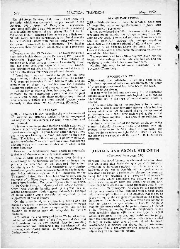
572 PRACTICAL
The 194 Strip, October, 1951, issue : I am using the 194 strip, which was converted, as per circuits in the October, 1951, issue of PRACTICAL TELEVISION.
After great difficulty I was able to get the strip working satisfactorily on removal of the resistor No. R.1, in the V.1 anode circuit. Situated here, as we are, a little over 50 miles away from the transmitter, it was found that the four V.R.65 R.F. stages were not just quite sufficient on the power transmitted at the moment. Two further stages were therefore added, which now gives a first -class picture.
Timehase on the £9 Televisor : The timebase circuit I am using is that shown in the December, 1951, issue of PRACTICAL TELEVISION, Fig. 4. This refused to function and, after various try -outs, I eventually found that the sync. separator valve V.14 had the control grid floating in the air, and this was connected to earth with a - MO resistor between the grid and chassis.
I found that it was not possible to get the line time base running at the correct speed and that the resistor R.53 required increasing from 1 MO to 2 MD, and on completion of these two modifications the timebase functioned satisfactorily and gives quite good linearity.
I would like to make it clear, however, that I do not consider by my suggestions above that the original circuits were wrong, only these modifications I found were necessary before the units would function satis- factorily in this area. -W. G. ROWELL (Dundee).
TELEVISION May, 1952
A FALLACY SIR, --There is a fallacy regarding the relative merits of
viewing and listening which is being propagated not only in the daily papers, but also in the columns of your journal.
It is surely unimaginative thinking which assumes an inherent superiority of programme merely by the addi- tion of viewed images. In your March editorial, you quote one newspaper likening the blind broadcast to the silent films. The fallacy of this analogy is patently obvious, as anyonç who has" viewed " without sound, and listened without vision will have no doubts as to which is the bigger handicap.
However, the fundamental point I wish to emphasise is that it all depends on the programme material.
There is little object in the music lover having a
visual image of the orchestra, in fact, such an image may properly be described as an . unwanted distraction. Certain types of plays lend themselves to visionless broadcasting -the visual images supplied by the-imagina- tion being infinitely superior to the limitations of the TV screen. Indeed, there have been several outstanding examples of brilliant playwriting, specifically intended for sound broadcasting. One which springs to mind being, L. du Garde Peach's " Mystery of the Marie Celeste" Only those severely handicapped by a gross lack of artistic appreciation would suggest that such an example of radio writing could possibly be improved by the supplement of visual images.
On the other hand, ballet, sporting events and the outside broadcast in general benefit immensely by means of the duo -channel. There is ample scope, too, for the creation of material especially adaptable to the TV medium.
Let us have TV, and more and better TV by all means, but let us not lose sight of the fundamental fact that each medium has its own special place in providing entertainment and broadening the experience of the listening and viewing public. -S. WOODHOUSE- HOLDEN
(Ashton- under -Lyne).
MAINS VARIATIONS SIR, -With reference to reader S. Wood of Stockport
regarding mains voltage fluctuations in April issue of PRACTICAL TELEVISION.
I, too, experienced the difficulties associated with badly regulated mains supply, the voltage varying from 190 volts to 230 volts. I managed to obtain from an adver- tiser an ex- R.A.F. carbon pile voltage regulator which cost in the neighbourhood of £5, and gives good regulation of all voltages above 180 volts. I do not know if these are still obtainable, but.suggest he contacts one of the advertisers.
The regulator is set to a voltage slightly lower than the lowest mains voltage, the set adjusted to suit, and the regulator cancels out all rises above this figure.
Hoping this may be of some assistance. -E. W. TEACHEN (Canterbury)
SPONSORED TV" SER, -Amid the hullabaloo which has been raised
about sponsored television programmes, the voice of those most concerned has been heard the least.
I refer to the viewer. It is he who has laid out the money for his expensive
apparatus, and it is therefore only logical that he should have some say in the type of entertainment which is
offered. The simple solution to the problem is for a voting
paper to be sent to each television licence holder for him to say whether or not he would like to see sponsored programmes for a short time each evening, for a trial period of three months. This should be sufficient to determine their value.
A final vote at the end of the period would settle the matter. I should like every reader who agrees with this scheme to write to his M.P. about it ; we won't get what we desire unless we fight for it ; after all we pay the piper so we should call the tune ! -B. L. MORLEY
(Bristol).
AERIALS AND SIGNAL STRENGTH (Continued from page 559)
portions that good balance is obtained between black and white and thus leave the sync pulse of sufficient amplitude to function satisfactorily. In other circuits, however, it will not be possible with a signal which is too strong to obtain a satisfactory picture, the contrast being too great resulting in a " soot and whitewash " effect, under which conditions the picture will not be worth viewing, apart from the effect the strong sync pulse may have on the particular timebases used in the receiver. in many respects the effect on the timebases will be very similar to that obtained with a weak pulse with the exception that it will be obvious that the pulse is too strong by the exaggerated contrast in the picture. In some receivers, however, where a sync pulse amplifier may be part of the sync separator circuits, the pulse may be too strong without the picture showing evidence of it. Generally, enquiry from the neighbours or the local . television dealer will reveal the type of signal which is obtained in the area and enable one to judge, from the specification of the receiver which it is intended to buy or build, what type of aerial should be fitted:' remembering, as pointed out above, that an attenuator is cheaper than a pre -amplifier and generally easier to adjust to give the required results.
May, 1952 Practical Television Classified Advertisements 573 HANNEY OF BATH oilers : View - master, Wearite Coils for Bir- mingham, Holme Moss and Kirk O'Shotts, 30/ , Constructors' Enve- lopes, 5/6, post free; WB100. 18 /6: WB101, 6/ -; WB102, 18!6; WBI03. 37/6; WB103A, 52/6; WB104, 15/6; WB105, 32/6. T.C.C. Condenser Kit, £7/7/ -. Morganite Resistors, 35/3. Type Q Pots. 51- each. Westinghouse Rectifiers, 36EHT100. 29/5; 14D36, 11/7; 14A86, 20/4; WX3 and WX6, 3/6 each. 6 Colvern Pots, 22/6. Bulgin Kit. 12/6. Pre -amp Coils, 5/- pair. Line Trans., 27/9; Frame Trans.. 22/6; Width Control, 10/ -; Boost Choke, 5/9; Tube Supports, 16/ -; Focus Ring, WB109, 1 (Mazda), 29/6; Focus Ring. Plessey 72005 ( Mullard), 22/8. Also Pre -Amp. Kits.
Console Conversion Kits, etc.; any item sold separately from 1 Resistor upwards. Cathode Ray Tubes, 9in., Mullard MW22 -14C, MW22 -17. MW22 -18, Mazda CRM92, £13/13/8, tax paid; 12in. Mollard MW31 -14C. MW31 -16, 17 and 18, Mazda CRM 121A and 121B. £18/4/10; Mazda CRM123, £2011014; Brimar C12B, £191714; also GEC and Ferranti. We pay. carriage on all Tubes and guar- antee safe delivery per passenger train (not sent COD). Send Gd. stamp for our new list which covers all TV designs and general Compon- ents. OWO or COD; all goods post free over £1. L. F. HANNEY. 77, Lower Bristol Road, Bath. (Tel.: 3811.) T.V. CONSOLE Cabinets, Radio- grams, L.S. Assemblies, etc. All re- quirements catered for up to the new 16in. tube. Write or phone ASHDOWN, 98. Hertford Rd., Edmon- ton. N.9. (TOT. 2621.) GUARANTEED VALVES: 6K8G, 6L6G, 6SN7GT, 6SL7GT, 11 /6; 6Q7G, ÚL41. 11/ -; 6V60, 5Z40, 5114G, 5Y3GT, 7C5, VU39, 0 / -; 1A5GT, 3Q5GT, .6X50T. 8 /6;. ILN5, 3D6, 7R?, 7/6. Special offer : 4 6J5GT for 15/ -; postage 6d.; c.w.o. or c.o.d. ELECTRO- SERVICES & CO., 28, Ethelburga St., S.W.11. (BAT. 2964.) LINE and Frame Scan Coils. 7/6; Line Transformer, 500/15 ohms, 7/6; Mains Transformer, 15/ -; EY51, 12/6; Thyratron CV1141, 6/ -; Gramoter, £2/10/ -; Emiscope, 15in. type, 3 '6A, Tube, £121101 -. COOK, 136, Basil - dene Rd.. Hounslow, Middx. "VIEWMASTER" Valves, as speci- fied, all guaranteed brand new and boxed. comprising 5 EF50, 1 KT61, 1 6P25, 1 EBC33, 1 EB91, 2 6K25, i 6P28. set of 12 £6/12/6; PL38, EY51, 18/6; PZ30, GZ32, 16/6; KT61, ECL80, 12/6; 50L6GT, 5Z4G. UF41, UBC41, 10/6; EF91, 6F12, 6AM6. EB91, 6AL5, AZ31. UY41, 10/ -; 6V6GT, 9/6. Miniature all -dry battery types. 1S5 I DAF91), 1R5 (DK91). IT4 (DF911, 3V4 IDL94). 8/9 each; EF39, EF50, EF8. KT2. 7/6; HVR2A, 6K7G, 2D4A, 6/6; 9D2, 4/6. All valves guaranteed brand new and boxed. C.W.O. Post paid 20/ -. READERS RADIO, 24, Colberg Place, Stamford Hill, London, N.16. RADIO AND T/V Constructors. For Components, Technical Advice, Re- ceiver Alignment. Rewinds, etc., con- tact GLYNDON RADIO SERVICE, 63, Glyndon Rd., S.E.18. (WOO. 2749.1 S.A.E. for list. FRESH STOCK CONDENSERS, 450vw, 8 mfd. 2/6; 16. 3/3; 8 x 8. 4/ -; 8 x 16. 4/3; 16 x 16, 4'6; 32 x 32, 6 /; 500vw, 8 mfd. 3/ -; 16. 4; -; .1-350v. 6/- doz.; .1 -500v. 7/- doz. Co -axial Cable, lin.. 80 ohm, 1/- yd. Semi - midget V /controls. 1 sp., 50 K. / -meg. and 2 -meg., 2/3. Rectifiers. 5Z4, 5Y3, 6X5. 9/- each. Special offer, 6K7G in original cartons, 4 for 23/6. List available. D. F. STRANGE, 52. Pendlestone Road, London, E.I7. tMail only.)
RATES : 3/- per line or part thereof, average live words to line. minimum 2 lines. Box No. 6d. extra. Advertisements must be prepaid and addressed to Advertisement Manager, " Practical Television," Tower house, Southampton St.. Strand, London, 1v.C.2.
SALVAGE VALVE sale, new, guaran- teed, boxed, at 8/9 each: EF37, EL9I, EF91, EF92, EB91, 6F6, Z77, 1A5, IRS, 1T4, 3S4. W17, X17, N17, DCC90, EF50 and EF36 Mullard, 5Z4, 6V6, 3A4. 6Q7. 6K7, 6X5. 5X4, EL33, EL32, KTW61, FW4, 500, AZ31, 3D6, SP4; to clear, 6/9 each, 12SK7, 1LN5, 1LD5, OZ4, Pen.220A, 8D2, 9D2, 15D2, EBC33, EF50, red XWD, Pen.383 (little dirty). 6N7, VP23, 1115, VPT210, KTZ41, KT33C, KT32C, VP133, 6J5, 6C5. Registered post 9d. Send stamp for list of other goods. DUKE'S, 621, Romford Road, Manor Park, E.12. (GRAngewood 6677.) COMPLETE KIT E.E. Television, in- cluding tube, cabinet; £35; 15, Christie St., Stockport. SALE, home -built Televisor, con- verted RDF1; Indicator Unit 182/A, Power Pack. B. CHEFFINGS, Grimoldby, Louth, Lincs. P.T. RECEIVER, complete set of Haynes' Transformers, Chokes and Scan Coils; brand new. List price. Box 125, C/O PRACTICAL TELEVISION. EX - SERVICES controls, remote ground station, type 10, rack -mounted panel Amplifier and Power Pack (less valves), suitable, slight modification, gramophone or public address ampli- fier, mains operated, 200/250 volts, AC, 2 PX25s in push -pull; price £4. Send for leaflet. THE RADIO EQUIP- MENT CO. (P.T.), Castor Road, Brixham, Devon. TV -ITIS, a complaint suffered by many who have no Black Screen. Our conversion kit will change your ordinary Television Set into a Black Screen Set; price 9/6, post free. Will fit any size of set from 12in. tube downwards, no suckers, no screws, no glue, and can be removed and replaced at any time. Trade enquiries invited. UNIT LIGHT MANUFACTURRING CO., 19, Queen Street, Blackpool. RELIABLE Mail Order Service-No ex- Government goods; Viewmaster Components, instructions, 51 -; en- graved knobs, white 1/6, brown 1/3; Morganite Resistor Kits,. individually labelled. 36/3; Potentiometer Kits, 28/6; T.C.C. Condensers, London £7, others 7 gns.; Console Cabinets, £9, del'd S. London; Adcola Irons, 22/6; Colour Filters. 12in. 12/6, 9in. 10/2, C.T.S. ELECTRONICS, 1, Pitlake, Croydon.
VALVES New Boxed and Guaranteed 6K8 ... 12'6 12K8 ... 12:6 EF55 ... 12 6 6E7 ... 71 12E7 ... 10.6 KT61 ... 12 6 6V6 ... 108 12Q7 .. 1116 ECL80 ... 12 6 5Z4 ... 9 6 351.6 ... 10 /6 EY91 ... 9 6
5134 ... 1016 3574 ... 116 1S , etc. 9 6 EF91 ... 11.6 6X5 .. 916 6J6 126 and hundreds of others. Lists, 3d. EX- EQUIP. -Soiled. Tested, O.K. VR91, SP61, SP41, 1553, VR56. 5 for £1. ELECTROLYTICS.- B.E.C. tub. midget, 8450 v., 2'6. Sprague. ditto, 2:6. B.E.C., 8 +8, 450 v., 4,'-. T.C.C. can, 16;450 v., 3:8. Ditto, 816 mid., 5' -. 8 mfd., Dub., Drilitic, 3/ -. 16 mfd., Drilitic, 4' -. T.C.C., 25:25 v., 1/9. VOL. CONTROLS (Midget).- Edlswan, guar. 12 months. All values. Long spindle. Less sw.. 3i -. S.P. sw., 4/ -. D.P.. sw., 49. 8052 COAX, lin. diam.. 10d. yd. Resistors,
w.. 4d. ; 1 w., 6d. M'core Solder. 16 g., 60,40 grade, 4d. yd. Post 6d. Over £1 FREE. T.R.S. 71 Meadvale Rd., E. Croydon ('allers 307, Whitehorse Road, West Croydon. Tho. 1665
T.V. TRANSFORMERS, 200/250v 30 c/s primaries, 425-0-425v, 350 nia, 6.3v 9 amps, 4v 6. amps. 451.; also 200v 30 ma, 6.3v 1.5 amps. for pre - Amplifiers, 10 / - Auto-Transformers, 230/115v 150 watts, 12/6; Smoothing Chokes, 10 H, 350 ma, 12/6: 10 H. 40ma. 2/6. Condensers, .25 mfd. 2,500v, 3 / -; 8 mfd, 1.000v, 5/ , Pre - Amp. Chassis, small, completely screened type. 1/3. B7G Valve - holders, Paxolin 6d.; Ceramic type with Screening Cans and retaining springs, 3/6; BOA Amphenol, with Cans, etc., 3/9. Germanium Diodes, 3/-. New and guaranteed Valves, 6J6. 6AK5, EC9I, X78, EY51, EL91, N78, 15/ -; 6X4, U78, EY9I, ECH42, 13/6; 6BA6, EF92, DH77. EF80, ECL80, EL42, UAF42, 185BT, 12/6; Z77, EF91, 6V6GT, KT61, 6L6G, 11/6; 1S5, 1T4. EF41, 6F6, VR105 /30, 10 / -; EB91, D77. 9/ -; 6AG5, 6K6GT, 5X4, 5Y4. VR150 /30, 8 /6: 1L4, 3A4, EF50, EF54, 7/6; 6C4. 2X2, 6/6; 954, SP61, 4/ -; EA50. 2/6. Send stamp for Bar- gain List. Postage 9d. on orders under £1. ELECTRAD RADIO, 69, High St., Belfast, N.I. HOME CONSTRUCTORS, short -wave radio or television. Send for free list components, valves, kits, speakers. etc. THE RADIO EQUIPMENT COMPANY (P.T.Dept.), Castor Road, Brixham, Devon. BARGAINS: Condensers 32/32 mid, 350vw, 2/6; 8/500, 2/6; 50/50, 2/6; 16 -8 -4- 4/500, 7/6; 16- 24/350, 5/ -; 1;450, 1/9; .5/2.5kV, 3/ -; .25 /2kV. 2/ -; Variables: twin 500pf, 5/6: with trimmers, 6/6; with drive. 6/6; single, 3/6; 4 gang, -7/6: 75pf D.E. 2/ -; twin 75 pf, 4 / -; single 50pf, 1/3; 25pf, 1/3. L.F Trans. for EHT 21[111, 7/6; Fil. Trans. 2v. la., 6 / -; (FT's 10/13mcs, canned, new, 1/6; Epicyclic Drives, 1/3; with pointer, 1/6; Spindle couplers, brass, flexible or insulated, 9d. Alladin lin. Formers (wound 30mes), cored, lad. Linecord, .3a 3 -way, 1I- yd., Rotary Toggles, 1/ -, Pre -amps type 6048, 17/6, less valves, 8/6. Formers, Dn. pax. slugged, 2in. z 4in.. 4 for 1/3; Valves at 3/6: VU111, CV54, VU120A, 2X2, VR65, VR65A, VR66, VR135, 6H6. VR21, 9004, VS70. 954, 956B; at 5/6; EF50, EF54, EC52, CV66, 68H7M, 6AC7, EF36. 12SK7: at 2/6: EA50, 7193, EB34. Most parts for " Argosy " in stock. C.W.O., postage extra. Queries s.a.e. pl. W. A. BENSON, 308. Rathbone Rd.. Liverpool, 13. CAR RADIOS, 6v. 12v; new; £13. GERRY, 22, Birkbeck Rd., Sidcup, Kent. A £1 in the hand -. Send me that' list of Valves you have for disposal and I will by return post offer you the best price for them. No lot too small or too large. NORMAN H. FIELD, 68, Hurst St., Birming- ham. 5.
' WANTED, Valves, small or large quantities, 6K8. 6V6. 5Z4, 6AC7, IRS, 155 FW4'500. 6Q7. 12K8, 80, VU39, EBC33, 3S4. etc., etc. Prompt cash. WM. CARVIS, 103, North Street, Leeds, 7. WANTED, T.V. Set, moderate price. Box 126. e 'o PRACTICAL TELEVISION.
SITUATION VACANT The engagement of persons answering these advertisements must be made through a Local Office of the Ministry of Labour or a Scheduled Employnunt Agency if the applicant is a man, aged 18-64, inclusive, or a woman aged 18 -56, inclusive, unless he or she, or the employment, is excepted from the provisions of the Notifica- tion of Vacancies Order, 1952.
TELEVISION ENGINEER required. Fully experienced only. Able to drive an advantage. Top wages offered. Apply IDEAL RADIO SERVICE, 362, High St., North, E.12.
574 PRACTICAL TELEVISION May, 1952
RADIO SUPPLY CO. 15, WELLINGTON ST., LEEDS, 1.
Post Terms C.W.O. or C.O.D. No C.O.D. under £1. Postage 1 - charged on orders up to £1 from £1 to £3 add 1/6 ; over £3 post free. Open to Callers 9 a.m. to 5.30 p.m. Saturdays until I p.m.
R.S.C. MAINS TRANSFORMERS P.M. SPEAKERS. All 2-8 ohms, 5in. F.W., 11/9 ; 5in. Rola with Trans.. 1519 :
611n. F.W., 13/11 sin. Plessey. 14111 ;
fully Guaranteed. Interleaved, and Impregnated. Primaries 200- 230 -250v. Bin. Rola. 17/6. : .10in. Goodman, 27'9. 50 cis Screened. M.E. SPEAKERS R.A. (2-3 ohms) Field
TOP SHROUDED. DROP THROUGH CHARGER TRANSFORMERS 600 ohms, 12/9. 10in. Plessey 3 ohms Field 260-0-260 v 70 ma.. 6.3 v 2 a., 5 v 2 a....14111 An with 200- 230-250 v 50 c/s Primaries 1000 ohms, 21)9. 260-0 -260 v 80 ma., 6.3 v 2 a.. 5 v 2 a.... 1411 0-9-15 v 1.5 a.. 14'9 : 0.9 -15 v 3 a.. 16/9 VOL. CONTROLS. All values. less switch. 350.0.350 v 80 ma.. 6.3 v 2 a.. 5 v 2 a... 17/8 0.9 -15 v 8 a., 22/9 : 0 -4 -9 -15-24 v 3 a., 22(9 2/9 with S.P. switch. 3111. 260.0.260 v 90 ma., 8.3 v 3 a., 5 v 2 a.... 19/9 0 -9 -15-30 v 3 a.... ... ... 23'9 BROWN BAKELITE CABINETS 350 -0 -350 v 90 ma., 6.3 v 3 a., 5 v 2 a.... 21/9 SMOOTHING CHOKES (PREMIER) 150-0-250 v 190 ma., 6.3 v 4 a., 5 v 3 a. 23.11 250 ma.. 8-10 h. 50 ohms ... ... 16/9 Size approx. 12-61 -53ín 350 -0-3.50 v 100 ma., 6.3 v-4v 4 a. C.T. 250 ma.. 3h. 100 ohms ... ... ... 8/9 Complete with punched (T.R.F.) Chassis,
200 ma. 5 h. 100 ohms ... ... ... 716 Coloured Station Named 2 or 3 wave Glass 350-0-350 v 120 ma., 6.3 v 4 a.. 5 v 3 a. 2841 100 ma. 10 h. 100 ohms... ... ... 7/6 Dial, Drive Drum. Cord Drive Head, Nylon 350-0-350 v 150 ma., 6.3 v 4 a.. 5 v 3 a. 29.'11 90 ma. 10 h. 100 ohms ... ... ... 5/9 Cord, Spring, and Dial Backplate, 28.6.
80 ma. 10 h. 350 ohms ... ... ... 5/6 T.R.F. Coils. Combined L. and M. wave. ELIMINATOR TRANSFORMERS with circuit. 6/8 pair. Primaries 200 -250 v 50 tics. 120 v. SELENIUM RECTIFIERS. Ex New
40 ma. 7/11 Equipment. 120 v 40 ma. (small), 49 :
120-0-120 v 30 ma., 4 v ï a. ... 12/9 New 36 v 50 ma., 11d. OUTPUT TRANSFORMERS MISC. ITEMS. Ex -Govt. (Trop.) Chokes, Midget Battery. Pentode 66 : 1 for 50 ma., 50 h. 1,000 ohms, 4'8. Philips Chokes,
3S4, etc. ... . .. 316 90 ma.. 8 h. 100 ohms. 4'6. Pye Coax Plugs Small Pentode, 5.000 ohms to 3 ohms 3/9 and Sockets. 7.6 doz. pairs. W.W. Pots.. Standard Pentode, 5010 to 3 ohms 49 5 k., 20 k., 50 k., 2/9 each. Cream Masks,
gin. (slightly soiled), 8/9. Suitable Armour plated glass, 1'11. EF50 Valves (ex. New Equip.), perfect condition. 6'6 each. ELECTROLYTICS. Tubular 8 mfd. 350 v 1/9 : 8 mfd. 450 v.. 2/3 ; Can 16 mfd. 450 v 2/11 : 8-8 mfd. 450 v.. 4'6 : 8-16 mfd. 450 v 4/6 ; 12 -12 mfd. 350 v. 31 : 16-16 mfd. 450 v 5/3 32 mfd. 350 v. 4'3 : 32 mfd. 450 v. 5'3 32-32 mfd. 350 v. 6.8 ; 32-32 mfd. 450 v. 69 32-32 mfd. 350 v. plus 25 mfd. 25 v. 5'8 32 -32-8 mfd. 350 v. 6'6 : 50 mid 350 y plus 250 mfd. 12 v, 4/3.
CLAMPED UPRIGHT MOUNTING 250- 0 -250v 80 ma., 6.3 v 3 a.. 5v 2a.... 18'9 250 -0-250 v100 ma.. 6.3 v6 a., 5 v 3 a.,
for 1355 conversion... ... 26.9 350 -0-350 v 100 ma.. 6.3 v 3 a., 5 v 3 a.. 23'9 350-0-350 v 150 ma., 6.3 v 4 a., 5 v 3 a. 29'11 FULI.V SHROUDED UPRIGHT 250 -0-250 v 60 ma., 6.3v 2 a., 5v 2 a.
Midget type 21-3 -3in. ... 17'6 250-0-250 v 100 ma., 0 -4-6.3 v 4 a., ratio 40 ma.. 30 : 1. 45:1, 300 -0-300 v 100 ma., 0-4-6.3 v 3 a., 69:1. 90 : 1 Class B Push -Pull ... 5/6
0-4-5 v 3 a. .. ... 25'9 350-0 -350v 70 ma., 6.3 v 2a., 5 v 2a.... 18'9 350-0-350 v 100 ma., 0 -4-6.3 v 4 a.,
0-4-5 v 3 a. .. ... 25'9 350-0 -350 v 150 ma.. 6.3 v 4 a., 5 v 3 a. 33'9 350-0350v 250 ma., 6.3v 6 a., 4v 8 a.
0 -2-6 v. 2 a., 4 v 3 a., for Electronic Eng. Televisor .. ... ... 67'6
425 -0-425 v 200 ma., 6.3 v 4 a.. C.T. 6.3 v 4 a.. C.T., 5 v 3 a., suitable Williamson Amplifier, etc. ... 51'-
325O325v20ma.,6.3v0.5a.,6.3v 1.5 a. for Williamson Preamplifier 17.8
FILAMENT TRANSFORMERS All with 200 -250 v. 50 cis primaries : 8.3 v MSP4. 5'8. 2 a..7ß : 0 -4-6.3 v 2 a.. 7'9 : 12 v 1 a.. 711 SPECIAL OFFERS. Mains Trans. 6.3 v 3 a.. 10'11 ; 6.3 v 6 a., 17/9: 0-2- 4 -5 -5.9 200.230 v Primaries, 6.3 v 1.5 a. small 59 4 a., 17 9 : 12 v 3 a., or 24 v. 1.5 a.... 17. Ex. Gov. Block Paper 4 mfd. 600 v 2'9
Push -Pull 0 watts 6V6 to 3 ohms ... 8/9 Push -Pull 10-12 watts 6V6 to 3 or 15
Push -Pull 10 -12 watt to match 61.6. PS4, 6V6, etc., to 3-5-8 or 15 ohms 16/11
Push -Pull 15 -18 watts to match 6L6. etc., to 3 or 15 ohm Speaker 229
NEW EX -GOV. VALVES. DI, l'3 EA50, 954, VU120A, 2'9 : 12116 Met., 1'11 9192. 2'11 : 12SG7 Met, 6J5GT, 128007 Met.
Met. 128117 Met. 6 9 ; 6K7G 6J7G,L KTZ63, Met, 7'8 : EF39, 6K6GT. 8 9 : 6 %SGT,
VP4B, PEN46. MHLD6, 9'6 : 5Y3G, EB91. 10'8 : 6070. 10'11 : ECL80, EF80. 12'11
FULL RANGE OF STANDARD COM- PONENTS AVAILABLE AT KEEN PRICES. ALL GOODS GUARANTEED AND NEW, UNLESS OTHER ISE STATED. QUANTITY QUOTATIONS GIVEN FOR STANDARD TYPES OR SPECIALS. S.A.E. PLEASE WITH ALL ENQUIRIES. FUI.L STOCK LIST 4d. SPECIAL LIST FOR TRADE. 4d.
QUALITY TELEVISION COMPONENTS SCANNING COILS
6/IO kV. R.F., E.H.T. UNITS E.H.T. and OUTPUT TRANSFORMERS
LINE FLY -BACK E.H.T. UNITS " TELEVISION CIRCUITS "
Third Edition, 64 pages, 2/6
HAYNES RADIO ltd., Queensway, Enfeld,
Middlesex.
VIEW MASTER SPECIAL OFFER
Complete set of resistors. Every resistor packeted and labelled with the value and position in the set.
London, 26/ -. All other models, 2419,
INSTRUCTION BOOKS View Master instruction books for all Models are available at 5/4, post free. A fully detailed list of View Master Components is available upon request.
WATTS RADIO (WEYBRIDGE) LTD. 8 Baker Street, Weybridge, Surrey.
Telephone : Weybridge 2542
NOW READY
For the
VIEWMASTER (KIRK o' SHOTTS) .
SETS OF COILS WIDTH CONTROLS BOOST CHOKES RF CHOKES
OLYMPIC RADIO COMPONENTS, COIL WINDING SPECIALISTS
224, HORNSEY ROAD, HOLLOWAY, N.7 Phone : NORth 2914.
VALVES or COMPONENTS? û
VALUE, QUALITY AND EXPRESS SERVICE FROM
COVENTRY RADIO COMPONENT SPECIALIST SINCE 1925
189, DUNSTABLE ROAD, LUTON, BEDS.
Phone : LUTON 2677
May, 1952 PRACTICAL TELEVISION 575
SOLVED Whilst we are a /wars pleased . to assist readers with
their technical difficulties, we regret that we are unable to supply diagrams or provide instructions for modifying surplus equipment. We cannot supply alternative details for constructional articles whicl, appear in these pages. WE CANNOT UNDERTAKE TO ANSWER QUERIES
OVER THE TELEPHONE. If a postal reply is required a stamped and addressed envelope must be enclosed.
VIEWMASTER- REDUCED SCAN " I am writing to ask your advice on a problem that
has arisen with my Viewmaster TV set. I am using a gin. tube, and have recently replaced the mains trans- former with a W.B.103A auto- transformer as the mains voltage in our district is 210 volts A.C. It improved the picture. But now a fault has developed that will not allow the picture to fill the screen area. The top and bottom edges of the picture do not reach the edges by about ein. with the height control at its maximum. Also the picture does not extend to the right -hand side of the screen by about lin., while the left -hand side is drawn out off the screen this is looking at the screen from the viewing position).
Ought I to have made the alterations to increase line and frame amplitude shown in your issue of ' Practical Tele- vision' June, '51, or is this only necessary when using a bigger screen ? " -R. R. (Northampton).
From the description of the fault which has developed in your receiver we believe MR4 has become faulty and should be changed. Before doing this, however, we suggest you carry out H.T. voltage checks and com- pare these with the figures specified in the Viewmaster booklet.
With the 9in. tube it should not be necessary to modify the time bases.
CHANNEL 5 COILS ON CHANNEL 4 I recently purchased a ' Premier' kit in London, in
anticipation of the opening of the new Wenvoe station. " The set in question is constructed to receive the
London programmes. " If 1 replace the existing London coils with those
appropriate to the new Wenvoe wavelengths, should I he able to receive Sutton Coldfield in the period before Wenvoe commences operations ?
" I ask this question in the light of the close proximity of the two wavelengths of Birmingham and Wenvoe. " - l-I. E. J. B. (Taunton).
Coils 'soundrfor Wenvoc should be able to receive the Birmingham transmission within the range of their cores, and in your case it is well worth doing as you suggest. You will, of course, have to tune any sound traps to the appropriate frequency as well, but this should not be a difficult task. A pre- amplifier will probably be necessary.
FRAME OUTPUT VALVE " I have an Ekco television with combined radio TS105
purchased in November, '49, and am now having a little trouble with the picture as it seems to roll up from the bottom to_ a; distance of about tin. and then after different periods of time it goes back to normal. There is also a width of brightness varying from din, to 'in. along the
bottom at the time which gives me indication that the picture is going to curl up. Can you give me some idea where to look for the trouble ? " -L. F. K. (S.E.7).
The most likely cause of this trouble is a falling frame output valve, the rolling -up effect you are experiencing being a form of non -linearity introduced as a result of this. A new frame valve will almost certainly correct the fault.
NEW TUBE FOR VIEWMASTER " As my Viewmaster manual is almost two years old
could you please advise me whether there are any improved tubes 112ín.) available since Ferranti T12/46 and Mullard MW22 -14C were specified ? In the March issue of P.T.' I see Mullard advertise the MW31 -16 which appears to include an ion trap. Would this tube be suitable for my standard circuit, also, what tube could I use if I adopt the modified circuit for aluminised tubes ? For my power supply from D.C. mains I am using a small D.C. motor, 1,500 r.p.m., 4 -pole, with sliprings tapped from segments 90 deg. apart. When used with an auto - transformer I get a good sine wave with a small ripple from the commutator segments superimposed on the main waveform. Do you think a full -wave rectifier is necessary in place of MR4 (14 -A -86) or is this only advised in the case of vibrator converters ? " -H. E. H. (Shrewsbury).
All of the C.R. tube manufacturers now produce improved tubes which may operate with up to 9 kV on the anode, thereby giving brighter pictures. The following are recommended :
G.E.C. type 6705A. Mullard type MW31 -16. Mazda type CRM123.
The Mullard tube with ion trap can certainly be used with the standard Viewmaster.
If your receiver has -been operating satisfactorily with a half -wave rectifier there does not seem any point in changing this for a full -wave type, though for a vibrator converter a full-wave rectifier would be essential.
NON -LINEARITY " I recently completed a television receiver, hut
unfortunately cannot get it to operate properly, and I think the trouble is mostly time bases and /or sync separator. I can get a picture of sorts at the top of the tube about Sin. deep, below this the lines open out to about tin. apart, and the whole lot flickers very badly. - The picture is fiat -
and lacks contrast, and is very dull. I am using a 12in. tube G.E.C. type 6706A aluminised, with about 64. kV on the anode (I intend to boost this to about 8,500 volts from the line output valve !). I am using a transformer. to provide the heaters with 10.5 volts at .3 amps : is there' any risk of blowing the heater with the surge when I' switch on ?
All deflector and focus coils are G.E.C. type for this tube. My time bases run side -by -side along the chassis, would it be better to rebuild it more widely separated ? Also, would an interlace filter improve the matter ? J. D. (Huthwaite).
The spreading of the lines over the lower part of your raster is obviously due to extreme non -linearity in the frame time -base circuit, and it is to this part of th4 circuit you must first look. The most obvious point is bad matching of the frame output transformer to the 6V6. You do not state whether the circuit y ,u are using is a published design recommending the com- ponents used, but on inspection the form of feedback and coupling used gives the impression tf,at the circuit is a specialised one which may have been designed for
576 PRACTICAL TELEVISION May, 1952
different output transformer and coils. A more con- ventional form of coupling and the use of a high -slope output valve such as an EL33 or KT61 with anode -grid feedback might be more suitable for your purposes ;
in any case, extensive changes will be necessary to the circuit as it now stands.
The positioning of the chassis has nothing to do with the above, and it is unlikely that an interlace filter of the type you mention will do anything to correct the raster. If your interlacing is bad after you have corrected the linearity, the filter should be built in, of course. Your tube heater arrangement should be satisfactory, but with an aluminised a higher E.H.T. (about 8 to 9 kV) is
necessary.
" PULLING ON WHITES " " I have completed and tested my Viewmaster and
find that the circle on the test card is slightly to one side. Would you please advise what I can do to correct this fault ? "-1. W. A. (Dunfermline).
The fault you describe is known as " pulling on whites ' and is possibly due to incorrect alignment of the visidh receiver. We suggest carefully re- aligning during the transmission of the test pattern and noting which of the iron dust cores affects this pull.
Occasionally R.21, C.I8 or R.20 may cause a similar effect.
R.F. INSTABILITY " My receiver is the ` Premier ' as advertised in ` P.T.'
and ` P.W.' using a magnetic tube. I made it up as a table model and it worked quite well, but recently I
decided to convert it into a console model. In doing this I had to separate the power pack and sound units. When all was ready I switched on and now find that the vision receiver goes into oscillation before I can increase the gain control to get a picture that will lock in either direction. I have examined all components and even replaced them, particularly in the controlled stages ;
also the valves, but the trouble still persists ; all voltages are correct. If I remove the first R.F. valve I find that I can advance the gain control right up without the screen going all white. Also I find that joining a piece of wire to sound chassis will control the oscillation a little when the other end of wire is joined to vision chassis. -R. B. (Stafford).
The first R.F. stage of the vision receiver isthe offending stage in your receiver, but the reason for the appearance of the instability is not so easy to pin down. It appears that coupling of some sort is now taking place through the chassis metal from a later vision stage to the first stage, but the manner in which this is occurring depends entirely on the form of layout you have now adopted. You should try bonding the vision and sound chassis together at various points with heavy flexible leads, but the main point of your work should be the location of a
coupling loop. if the trouble persists, you must re -check the first R.F. stage and use only one common chassis return for all the wiring associated with it.
POOR DEFINITION ?
" I wonder if you could solve a problem I have with
my Viewmaster, fitted with a 12in. Mazda tube ? I have
had the set going for about eight months and have had a
fairly good picture, but it will not resolve the lines on
test card C as it should : that is, the lines from the bottom
left upwards and the right downwards. I have made many inquiries, but can get no solution to this problem, so would be very grateful for your help if possible. - G. B. (Redhill) .
We presume that you can resolve at least some of the wider lines in the gradings, equivalent to 1, 1¡, or even 2 Mc /s.
Poor definition, assuming that there are no obvious faults in the receiver, is due to incorrect alignment, and we can only suggest that you re -align the receiver, following closely the instructions in the Viewmaster booklet and, if possible, doing this with the aid of a signal generator.
PICTURE PROPORTIONS " I have purchased, some three months ago, a R.G.D.
12in. Televisor, model H 1700, incorporating a Ferranti flat -faced tube. The set works well, except that at either side of the mask I have a black strip of approximately tin. showing, this being the maximum width I can obtain with the width control. If I turn up the contrast control the picture fills the width of the mask, but becomes too bright. I have experimented with various types of aerial without improvement. I suspect the set to be a Sutton Coldlield model that has been converted by the dealer, who does not seem to want to give any service in the matter and maintains that it is in order. Most of my friends have the round -faced tube and the picture in each case fills the mask. I wonder if you could inform me if I am expecting too much ? " -E. L. T. (Liverpool).
If your mask is of correct aspect ratio (4 : 3), the picture should fill the area correctly without black bands showing at the sides. If the picture height is sufficient just to fill the mask area correctly, however, and the sides then fall short, then. if the picture is correctly proportioned as per test card C, there is little you can do. Since the picture is expanded by brightness, the E.H.T. regulation is poor, and a reduction in E.H.T. might enable you to fill the area properly. Your aerial system has nothing to do with the fault.
H.T. FAILING " T have built a set with VCR97 from a kit of parts
supplied by Premier Radio. This set has worked splendidly until recently, when it has developed a fault. This consists of a slight hum on the sound and also the vertical edges of the picture have developed a bulge.
This bulge affects the whole picture, which is distorted to the right. The remainder of the picture is all right. The bulge is not always in the same position : sometimes at the top, then in the middle or at the bottom, the position changing only when the set is switched off, and then, of course, on.
" Another fault which comes on very infrequently is a crackling noise in the sound accompanied by shooting black lines across the picture. This may just happen once, or it may continue until the set is switched off. The fault may then not develop again for a few weeks." - R. H. B. (Dalton).
From your description of the fault it seems that the trouble is associated with the H.T. supply to the receiver, and the most probable points to check are the H.T. rectifier valves and all smoothing circuits, particularly electrolytic condensers. The best approach is to replace the latter one at a time by a suitable substitute ; a 16 1SF.
would be suitable for all those already included in the set.
printed in Enggllan y W. SPEAIGHT & SONS, L .WÉ moorlSttreeee , London, W.l0. Southampton
So ents for Austrraalia and London. Zealand
GORDON & GOTCH (Alsia). LTD. South Africa : CENTRAL NEWS AGENCY. LTD. Subscription rate including tageP one year : Inland and Abroad las. 6d. (Canada las.). Registered at the General Post Office for the Canadian Magazine
May, 1952 PRACTICAL TELEVISION
BO AIDS TO IMPROVE -6Rkvt'vi3':on
YOUR
TELEVISION RECEPTION
T.V. Pre -amplifier ... _r. T.V. Pre -amplifier ...
Sound & Vision Test Units
£7.17.6 each unit.
E5. I7.6 £7. 10.0
6 Outlet T.V. Pre -amplifier
£6.15.0
DESCRIPTIVE LEAFLETS FORWARDED WITH
PLEASURE
RAINBOW' R A D I O MFG. CO. LTD. rí!NCIiVG LANE, BLACKBURN, LANCS.
III
B.P.L. SUPER RANGER 1,000 o.`,ms por vak- 20,027 ohms per volt.
A precision built instrument of high accuracy equipped with a tine Stn. movement in spring loaded sapphires.
Fitted with mirror scale. The range selector is of sturdy construction, consisting of solid
silver contacts mounted on a ceramic base. By means of this switch all ranges are selected except the A.C. current ranges and the 5.000 volts range.
Provided with A.C. current ranges which, in conjunction with the other ranges, will cover all ranges to be exsected.
LIST PRICE :
£19.19.0. 1.007 ohms per volt. £22.15.0, 20,01) ohms per volt. Subject to Trade Discount.
LONDON STOCKIST :
M.R. SUPPLIES LTD., 68. NEW OXFORD ST., W.C.I
Leathe carrying handle. Captive head terminal con-
nectors for all ranges. Easy to read 2- colour dial. 0,000 volts range for A.C. and
D.C. 1,003 ohms per volt and 20,00)
. ohms per volt for D.C. and A.C.
Rotary switch selects ranges clearly marked. sin. scale meter with mirror scale. Movement fitted vita spring loaded sapphires. Built -in 3 range current trans- former.
BRITISH PHYS L. BORATORIES HOUSEBOAT WORKS V DLETT HEATS
Telephone i iIBL T 5674.5 -6
DELIVERY EX -STOCK
NORMAN D. HELD 7
C8, HURST ST., EIRMINGHAM, 5, Mail Order Dept.
04-65, CHURCH LANE, WOLVERHAMPTON.
VALVES `t 11/6 : GROG, 5114G. ECC32, 5Y3,5Z4,
.-dGT,-6Q7, X61, 6SN7, KTO6. 6F6, 807, 6K6. 10i- : 1616, 6SQ7, PI:N46, 50YG/GT.
. 9/- : 6F7, ARP6, 6X5, KT63, 1T4. 1S1, .3, 155. At 8 : V P.52, EL32. V R.55, 12SL7. 7'6: 7R7, 77, 6K7, 6J7, VR150, 6G6'GT,
VR119, 6Y7,G, 7C5, OZ4, 12A6, 12AC7, R133. At 7,- : 6B3, 6B3G, 1G6'G'l',C,
1A5/G1`, 6X7G, VR53, EF39, EF36. At 66 :
CAB?, ARPI@, VP23. At 5'8 : 6SS7, 12.13, RK3l, 6SH7. VR91, F.F52, 3D6, TT11, VT501. At 5'-: 6J5, 12SK7, 6SK7/GT. 2A3, VU133. 1625, VT51, PEN220A, VR119, KT2. At 413 :.
CR65, SP61, 6J,'SG, 6J5GT, 12S1T7, 12103, VUI20. At 3B : 'RKR72, ARP3, 9D2 6H6. At 3/3 : Vlils, 2C34, RK34, VU133, 15SG, VU111, 111,2, VR217 VR66, P61, VR55A, SP41. At 2,6 : VR54, EB34, VR92, EA50, VR7d, Dl, CV6. -
SPECIAL OFFER KIT OT VIEWMASTER VALVES
AT HALF PRICE Le.4.0 VIEWMASTER
Coll Kits, Holme Moss and Birmingham :
14 Coils and 1 R.F. Choke, 21.'6. Plessey Focus Ring 72004, 22 6. Scanning Coils. 29/3. Width Control, 7,6. Heater Transformer, 25/8. Frame Transformer, 19/9. Mlcadiscs 500 pF., 1,6 each.
r.n.T. TRANSFORMER *.- 2,590v. 5M A, 4v. 2 amp.,- 0 -2-4v. 4 amp.. 210 -250v. 50 cycles. Completely wax impregnated. 45/- each. Please include something Cor post. Money
Back Guarantee.
TRANSFORMERS No. 1. 270- 0 -25:v. BO ma. 0 -4v. ha. 0.2v.
3,5a. 0 -4 -5v. 2a., 17' -- No. 2. As No. 1 but 357- 0 -353v.. 17' , Nu. 3. 26v. 2. /a. tapped to give almost
any voltage u) to 26v. ideal for chargers, models, W.D. motors, etc., 16, 6. No. 4. 4v.- 9v. -20v. 4 amp. For 2, 6 en; 12 volt chargers, 18' -. Nó. 5. Auto wound, 10-0 -110- 203 -230- 250v. 157 watts. For general voltage changing, up or down, 16,6. No. 6. 250 -0- -250v. 100
ma. 0.3v. 3.5a. 5v. 2a.. 22/ , No. 7. Telev'sion Auto with overwind.
0 -20.0 -235- 250 -2110v. 500 ma. 6.3v. 7 amps. 0- 2 -6.3v. 2 amps, 38,6.
All types upright or drop through. No others available. Primaries on 1, 2, 4 and 6 tapped 230 -230 -250v. Interleaved, Im- pregnated. Screened, Guaranteed. Terms : C.W.O., C.O.D. or pro forma.
Postage 1/6 1 to 3.
HILLFIELDS RADIO, 8, BURNHAM ROAD, WHITLEY, COVENTRY
VIEWMASTER Exact specified parts at Shopping List prices by return post. H.M., B'ham, and Scottish. Also valves and tubes.
H.G. RADIO ELECTRICAL CO. 1350, Stratford Rd., Birmingham, 28 'Phcne: Springfield 2369. Estb. 25 years
G.E.C. & B.T.H. ó
GERMANIUM CRYSTAL DIODES G.E.C. GLASS TYPE 3 /16in. x i',r,i n. B.T.H. LATEST TYPE MOULDED iN
THERMO -SETTING PLASTIC Both Wire Ends for Easy Fixing.
4!6 each, postage 21d. SILICON CRYSTAL VALVE
316 each, postage 21d. Fixing Brackets 3d. Extra.
Wiring instructions for a cheap, simple but high quality Crystal Set included with each Diode and Crystal Valve.
COPPER INSTRUMENT WIRE ENAMELLED, TINNED LITZ,
COTTON AND SILK COVERED. Most gauges available.
B.A. SCREWS, NUTS, WASHERS soldering tags, eyelets and rivets.
EBONITE AND BAKELITE PANELS, TUFNOL ROD, PAXOLIN TYPE COIL
FORMERS AND TUBES, ALL DIAMETERS.
Latest Radio Publications. SEND STAMP FOR LISTS.
CRYSTAL SET INCORPORATING THE SILICON
CRYSTAL VALVE Adjusted Iron Cored Coil.
RECEPTION GUARANTEED Polished wood cabinet, IS1 -, post 9d, A REAL CRYSTAL SET, NOT A TOY
POST RADIO SUPPLIES 33 Bourne Gardens, London. E.4
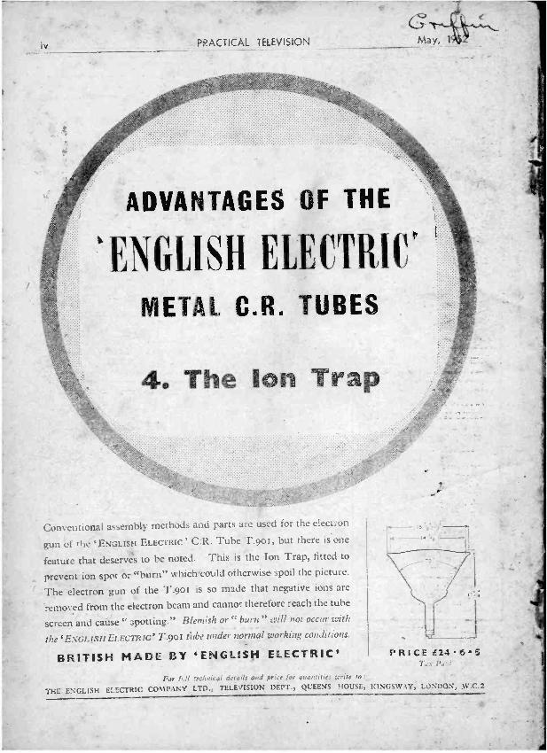
_ -
4
iv. PRACTICAL TELEVISION
ADVANTAGES OF THE
'ENGLISH ELECTRIC°
METAL C.R. TUBES
40 The ion Trap
Conventional as ,embly method', and parts are used for the electron
gun of rile 'ENGLISH ELECTRIC' C:R. Tube T.9o5, but there is one
feature that deservA to be noted. This is the Ion Trap, fitted to
prevent ion spot or "burn" which.could otherwise spoil the picture.
The electrOn gun of the T.9o1 is so made that negative ions are
removed from the electron beam and cannot therefore reach the tube
screen and cause " ',Totting." Blemish or " burn" will ;Mt occur with
the ENGLISH ELECTRIC' T.90I debe under normal working conditions.
BRITISH MADE BY 'ENGLISH ELECTRIC'
Far r.11 r:clmical derails and price I
.-ing ENGLISH ELECTRIC COMPANY LTD., TELEVISION DEPT., QUEENS HOUSL,
rk
-!;
PRICE i2485
KINGSWAY, LONDON, W.C.2