Embed Size (px)
Citation preview
An Overview of X-ray Polarimetry of Astronomical Sources
Martin C. Weisskopf
(NASA/Marshall Space Flight Center)
Alsatian Workshop on X-ray Polarimetry, Strasbourg France, November 13, 2017
1

• A look to the past• Experimental techniques
• Electron tracking
• IXPE the mission
• IXPE the science
Outline
2

• The degree of polarization and the “position angle” depend onthe conditions under which the X-rays are produced
• Thus modeling of what we see must also predict the degree ofpolarization and the position angle
Why is polarization useful?
3
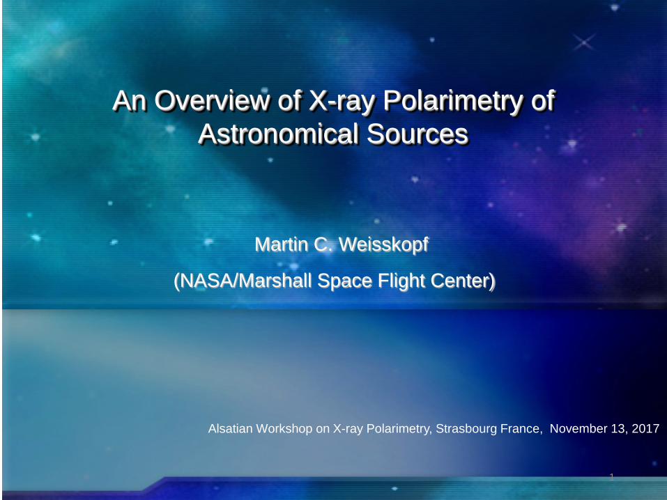
In the beginning
• July 1968 – Lithium-block, “Thomson”-scattering polarimeter flown on an Aerobee -150 rocket– Target was the brightest X-ray source Sco X-1
4

Scattering polarimeter
• Thomson cross-section approximates the angular dependence
• From bound electrons one must account for both coherent andincoherent scattering and photoelectric absorption
)sincos(cos)/(/ 222222 ϕϕϑσ +=Ω mcedd
Ird
d
Frd
d
⟩+⟨=Ω
⟩+⟨=Ω
ϕϕϑσ
ϕϕϑσ
22220
incoh
222220
coh
sincoscos
sincoscos
5
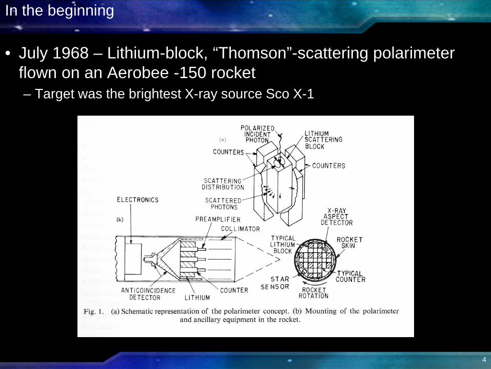
Thompson approximation
Cos (polar scattering angle) Azimuthal scattering angle
6

Considerations
• Minimize the background• Achieve as large a sensitivity to polarization as possible
– Optimize the “MDP” at the 99% confidence level
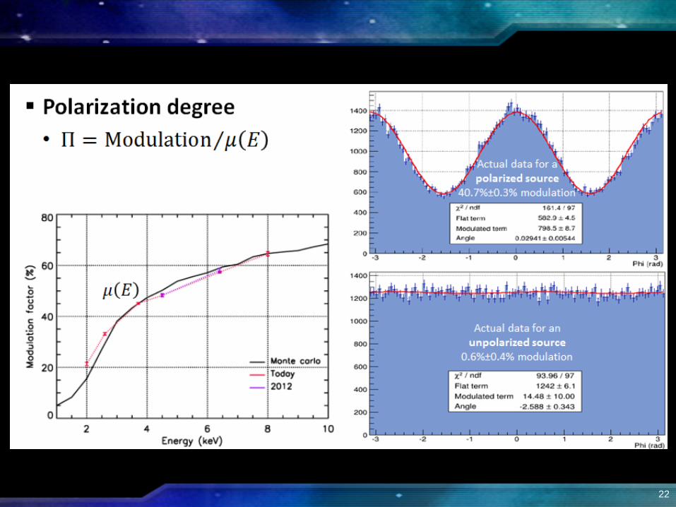
tRRRMxMDP SBS24 /)((%))/1029.4((%)99 +=
• MDP is the degree of polarization detected at the 99% confidence independent of the position angle
• M is the modulation from a 100% polarized beam with RB = 0
7
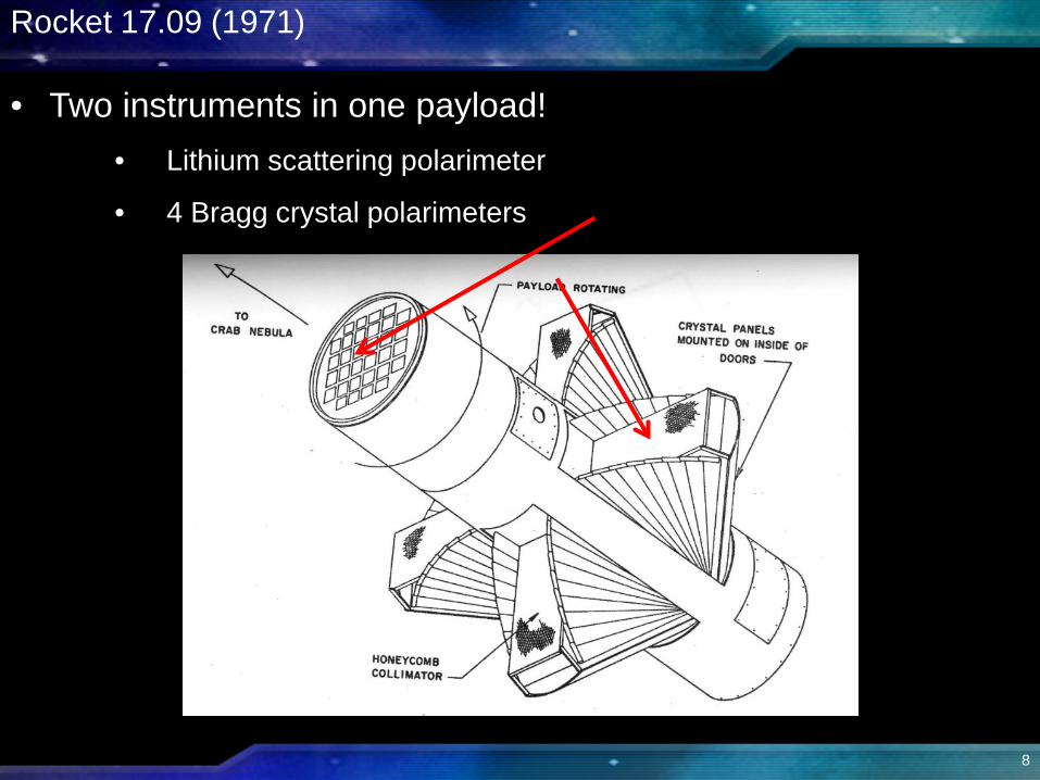
• Two instruments in one payload!• Lithium scattering polarimeter
• 4 Bragg crystal polarimeters
Rocket 17.09 (1971)
8
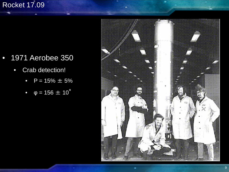
• 1971 Aerobee 350• Crab detection!
• P = 15% ± 5%
• φ = 156 ± 10°
Rocket 17.09
9
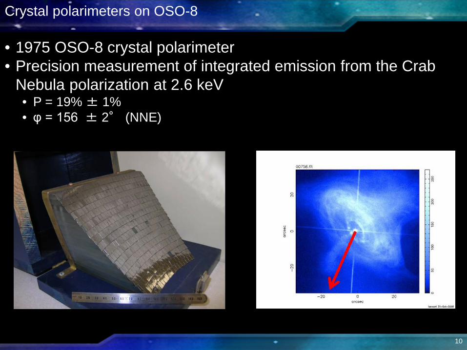
Crystal polarimeters on OSO-8
• 1975 OSO-8 crystal polarimeter• Precision measurement of integrated emission from the Crab
Nebula polarization at 2.6 keV• P = 19% ± 1% • φ = 156 ± 2° (NNE)
10
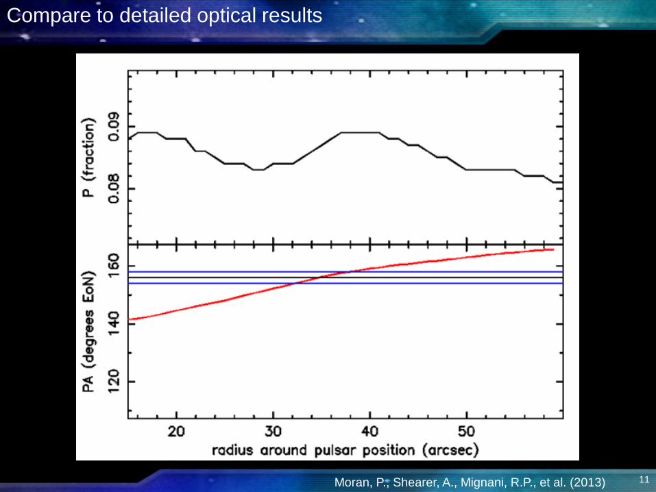
Compare to detailed optical results
Moran, P., Shearer, A., Mignani, R.P., et al. (2013) 11
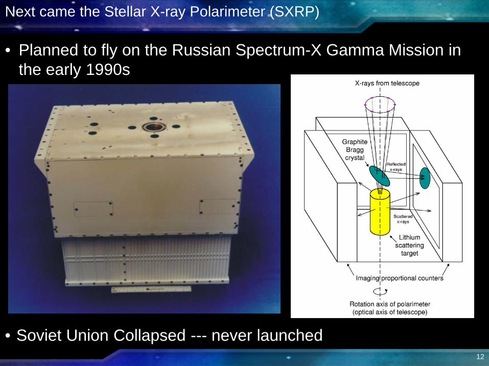
Next came the Stellar X-ray Polarimeter (SXRP)
• Soviet Union Collapsed --- never launched
• Planned to fly on the Russian Spectrum-X Gamma Mission in the early 1990s
12

Breakthrough --- electron-tracking polarimeters
• Optical Imaging Chamber • Austin & Ramsey 1992
• Pixelated Gas Multiplication • Costa et al. 2001
• Time Projection Chamber • Black et al. 2007
• The direction of the initial K-shell photoelectron is determined by the electric vector and the direction of the incoming photon
ϕθν
αζσ 222/72
40
520 cos sin24)(
=
Ω hmcZrf
dd
13
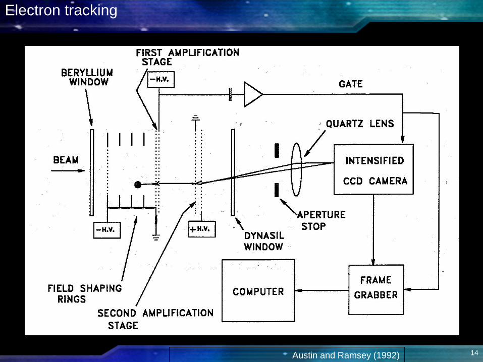
Electron tracking
Austin and Ramsey (1992) 14
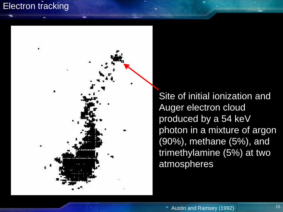
Site of initial ionization and Auger electron cloud produced by a 54 keV photon in a mixture of argon (90%), methane (5%), and trimethylamine (5%) at two atmospheres
Electron tracking
Austin and Ramsey (1992) 15
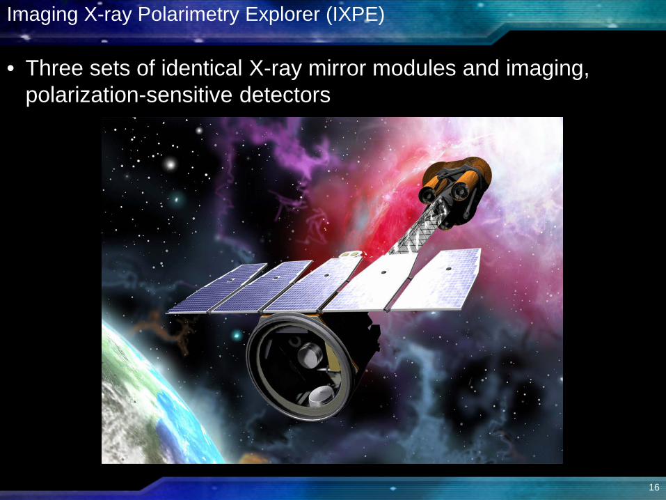
Imaging X-ray Polarimetry Explorer (IXPE)
• Three sets of identical X-ray mirror modules and imaging, polarization-sensitive detectors
16
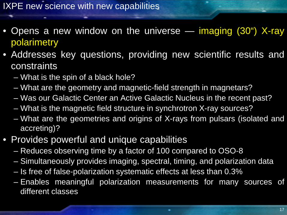
IXPE new science with new capabilities
• Opens a new window on the universe — imaging (30“) X-raypolarimetry
• Addresses key questions, providing new scientific results andconstraints– What is the spin of a black hole?– What are the geometry and magnetic-field strength in magnetars?– Was our Galactic Center an Active Galactic Nucleus in the recent past?– What is the magnetic field structure in synchrotron X-ray sources?– What are the geometries and origins of X-rays from pulsars (isolated and
accreting)?• Provides powerful and unique capabilities
– Reduces observing time by a factor of 100 compared to OSO-8– Simultaneously provides imaging, spectral, timing, and polarization data– Is free of false-polarization systematic effects at less than 0.3%– Enables meaningful polarization measurements for many sources of
different classes
17
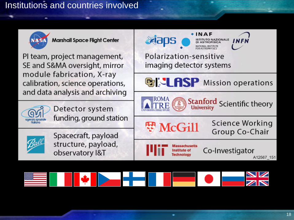
Institutions and countries involved
18

The Science Team
Co-InvestigatorsLuca Baldini, Ronaldo Bellazzini, Enrico Costa,
Ronald Elsner, Victoria Kaspi, Jeffery Kolodziejczak, Luca Latronico, Herman Marshall, Giorgio Matt,
Fabio Muleri, Stephen L. O’Dell, Brian D. Ramsey, Roger W. Romani, Paolo Soffitta, Allyn Tennant
CollaboratorsW. Baumgartner, A. Brez, N. Bucciantini, E. Churazov, S. Citrano, E. Del
Monte, N. Di Lalla, I. Donnarumma, M. Dovčiak, Y. Evangelista, S. Fabiani, R. Goosmann, S. Gunji, V. Karas,
M. Kuss, A. Manfreda, F. Marin, M. Minuti, N. Omodei, L. Pacciani, G. Pavlov, M. Pesce-Rollins, P.-O. Petrucci, M. Pinchera,
J. Poutanen, M. Razzano, A. Rubini, M. Salvati, C. Sgrò, F. Spada, G. Spandre, L. Stella, R. Sunyaev, R. Taverna,
R. Turolla, K. Wu, S. Zane, D. Zanetti
19
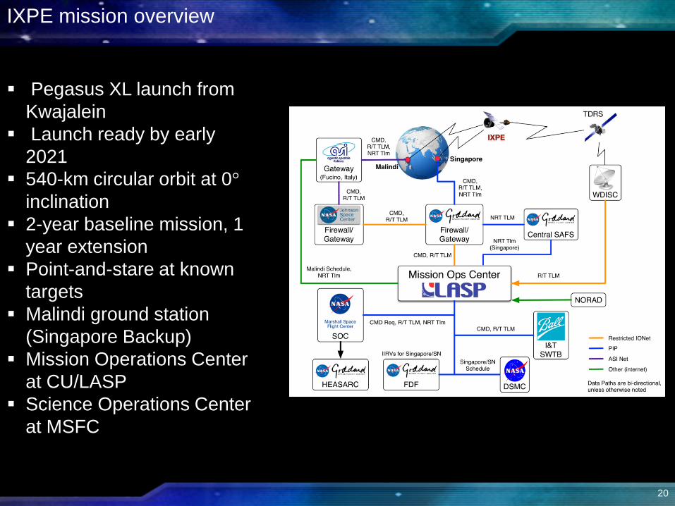
Pegasus XL launch from Kwajalein
Launch ready by early 2021
540-km circular orbit at 0°inclination
2-year baseline mission, 1 year extension
Point-and-stare at known targets
Malindi ground station(Singapore Backup)
Mission Operations Center at CU/LASP
Science Operations Center at MSFC
IXPE mission overview
20

IXPE deployed
21
22
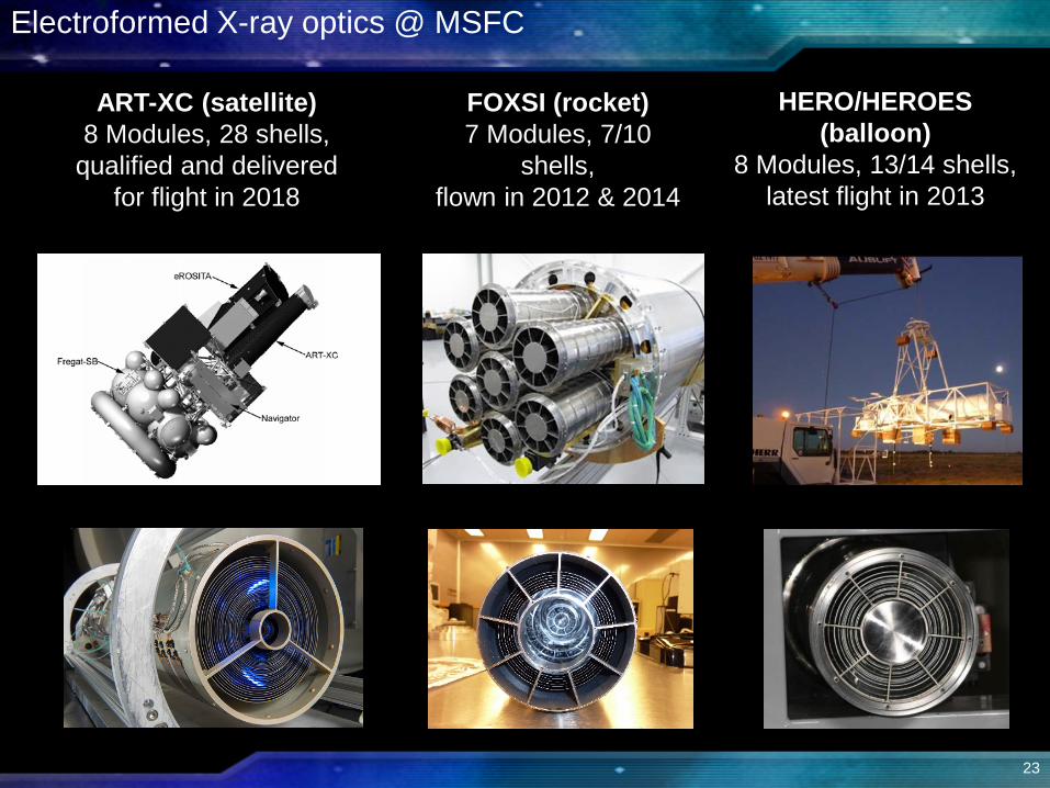
Electroformed X-ray optics @ MSFC
ART-XC (satellite)8 Modules, 28 shells,
qualified and delivered for flight in 2018
FOXSI (rocket)7 Modules, 7/10
shells,flown in 2012 & 2014
HERO/HEROES (balloon)
8 Modules, 13/14 shells,latest flight in 2013
23
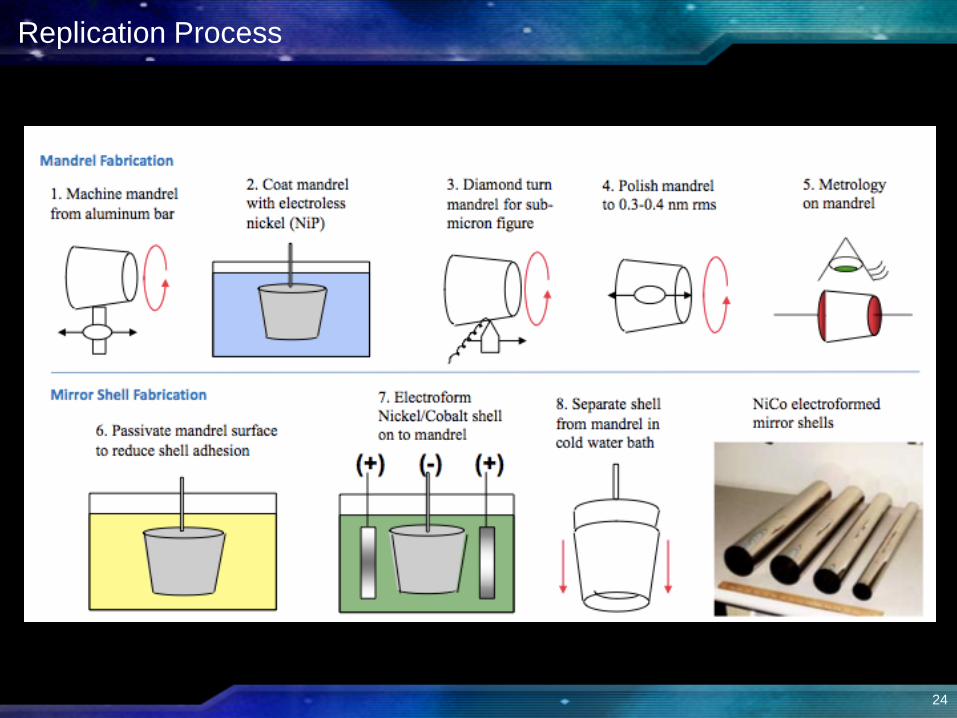
Replication Process
24
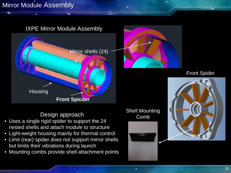
Shell Mounting Comb
IXPE Mirror Module Assembly
Design approach • Uses a single rigid spider to support the 24
nested shells and attach module to structure • Light-weight housing mainly for thermal control• Limit (rear) spider does not support mirror shells
but limits their vibrations during launch• Mounting combs provide shell attachment points
Front Spider
Mirror shells (24)
HousingFront Spicder
Mirror Module Assembly
25
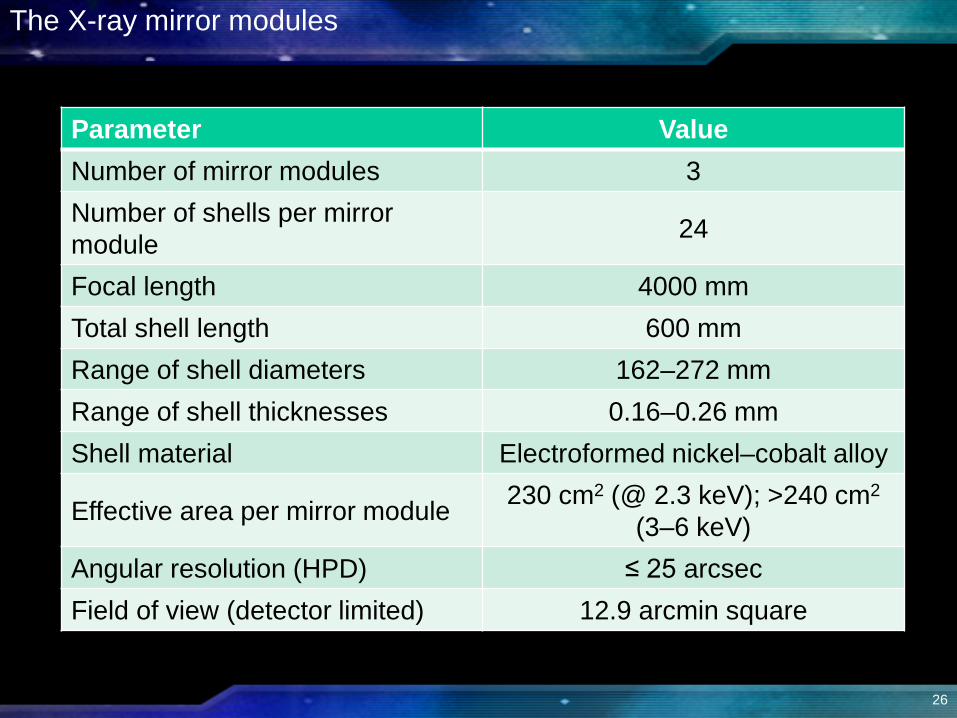
The X-ray mirror modules
Parameter ValueNumber of mirror modules 3Number of shells per mirror module 24
Focal length 4000 mmTotal shell length 600 mmRange of shell diameters 162–272 mmRange of shell thicknesses 0.16–0.26 mmShell material Electroformed nickel–cobalt alloy
Effective area per mirror module 230 cm2 (@ 2.3 keV); >240 cm2
(3–6 keV)Angular resolution (HPD) ≤ 25 arcsecField of view (detector limited) 12.9 arcmin square
26
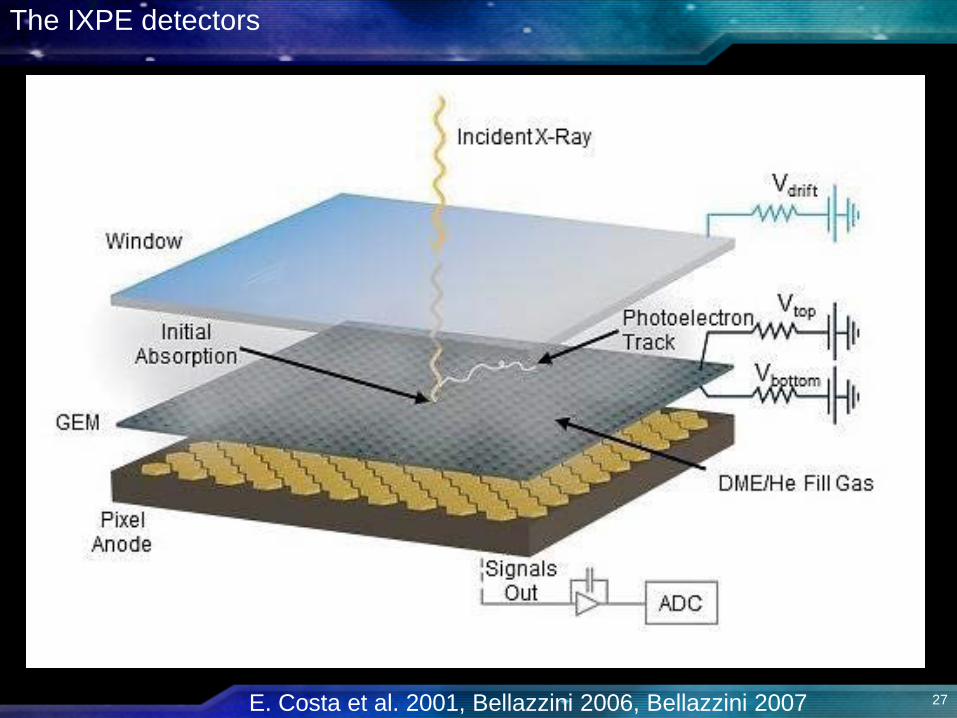
The IXPE detectors
E. Costa et al. 2001, Bellazzini 2006, Bellazzini 2007 27
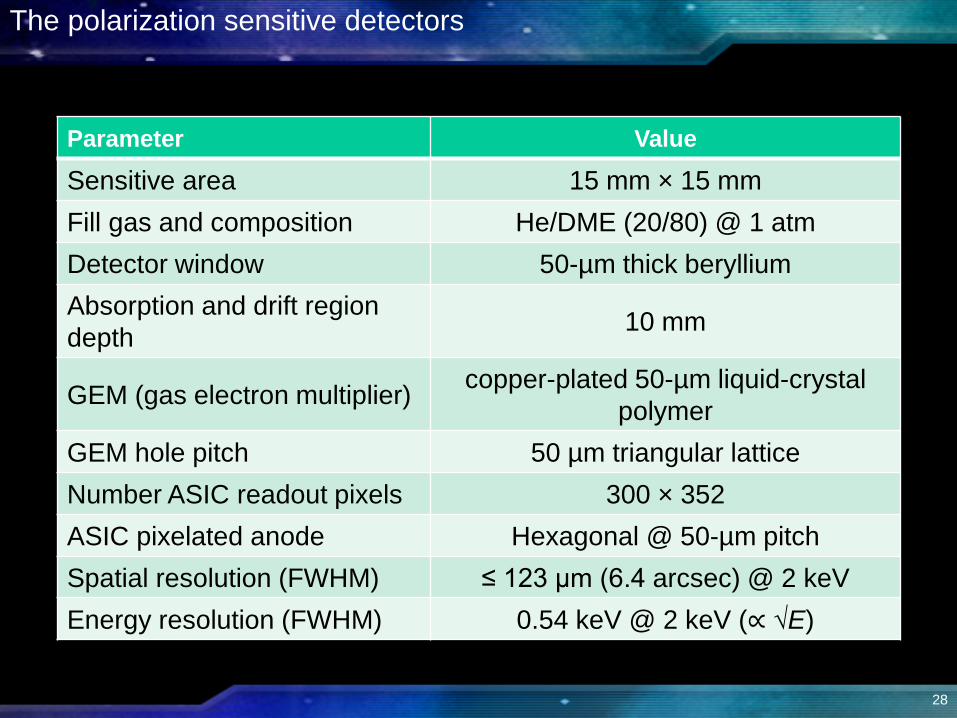
The polarization sensitive detectors
Parameter Value
Sensitive area 15 mm × 15 mmFill gas and composition He/DME (20/80) @ 1 atmDetector window 50-µm thick berylliumAbsorption and drift region depth 10 mm
GEM (gas electron multiplier) copper-plated 50-µm liquid-crystal polymer
GEM hole pitch 50 µm triangular latticeNumber ASIC readout pixels 300 × 352ASIC pixelated anode Hexagonal @ 50-µm pitchSpatial resolution (FWHM) ≤ 123 µm (6.4 arcsec) @ 2 keVEnergy resolution (FWHM) 0.54 keV @ 2 keV (∝ √E)
28

• For a micro-quasar GRX1915+105 in an accretion dominated state– Scattering polarizes the thermal disk emission– Polarization rotation is greatest for emission from inner disk
• Inner disk is hotter, producing higher energy X-rays– Priors on disk orientation also constrain model
a = 0.50±0.04; 0.900±0.008; 0.99800±0.00003 (200-ks observation)
Measure black-hole spin in twisted space-time
29

Map magnetic field of synchrotron sources
• Probe sites of cosmic-ray acceleration: Cas A– Lines and thermal continuum dominate 1-4 keV– Non-thermal emission dominates 4-6 keV
Cas A image at IXPE resolution (1.5-Ms)
HPD
30
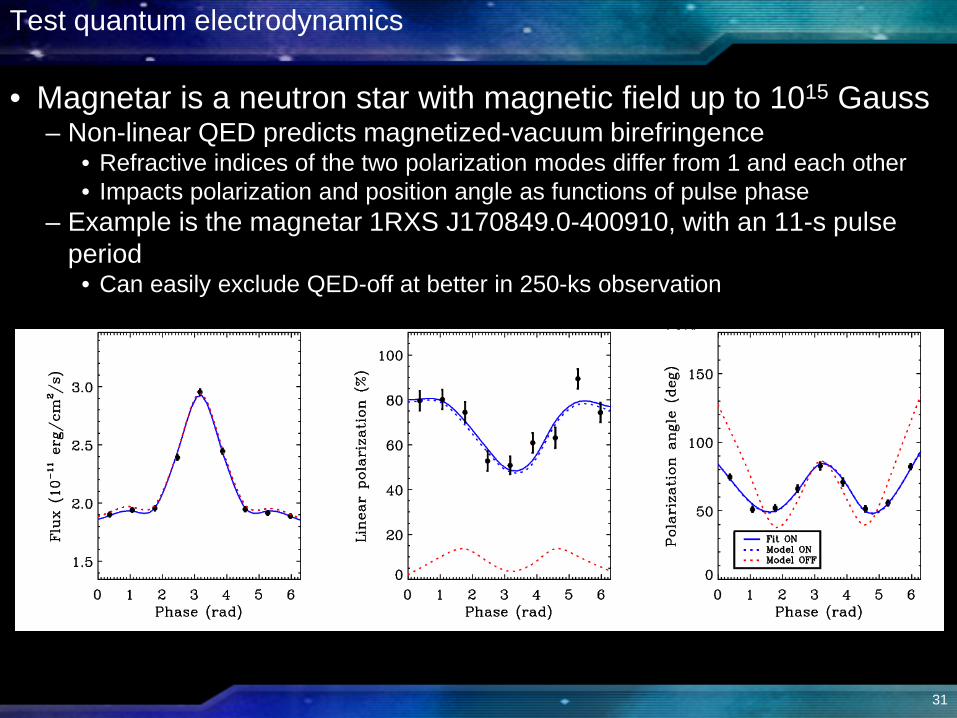
Test quantum electrodynamics
• Magnetar is a neutron star with magnetic field up to 1015 Gauss– Non-linear QED predicts magnetized-vacuum birefringence
• Refractive indices of the two polarization modes differ from 1 and each other• Impacts polarization and position angle as functions of pulse phase
– Example is the magnetar 1RXS J170849.0-400910, with an 11-s pulse period
• Can easily exclude QED-off at better in 250-ks observation
31
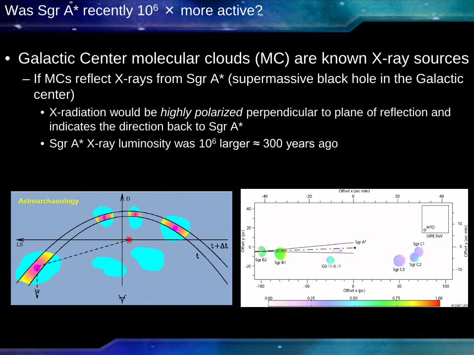
Was Sgr A* recently 106 × more active?
• Galactic Center molecular clouds (MC) are known X-ray sources– If MCs reflect X-rays from Sgr A* (supermassive black hole in the Galactic
center)• X-radiation would be highly polarized perpendicular to plane of reflection and
indicates the direction back to Sgr A*• Sgr A* X-ray luminosity was 106 larger ≈ 300 years ago

Phase-resolved polarimetry: Crab Pulsar
• Emission geometry and processes are unsettled– Competing models predict differing
polarization behavior with pulse phase
• X-rays provide clean probe of geometry– process entirely different in radio band– We recently discovered no pulse phase-
dependent variation in polarization degree and position angle @ 1.4 GHz
– Absorption likely more prevalent in visible band
• 140-ks observation gives ample statistics to track polarization degree and position angle
Grey = optical

IXPE imaging of AGN
• Active galaxies are powered by supermassive BHs with jets • Radio polarization implies the magnetic field is aligned with jet• Different models for electron acceleration predict different dependence in
X-rays Cen A allows isolating other sources in the field
• Two Ultra Luminous X-ray sources (one to SW on detector but not visible in 6-arcmin-square displayed region)
Region MDP99
Core <7.0%Jet 10.9%
Knot A+B 17.6%
Knot C 16.5%Knot F 23.5%Knot G 30.9%
ULX 14.8%Includes effects of dilution by unpolarized diffuse emission

Capturing the imagination
35