Embed Size (px)
Citation preview
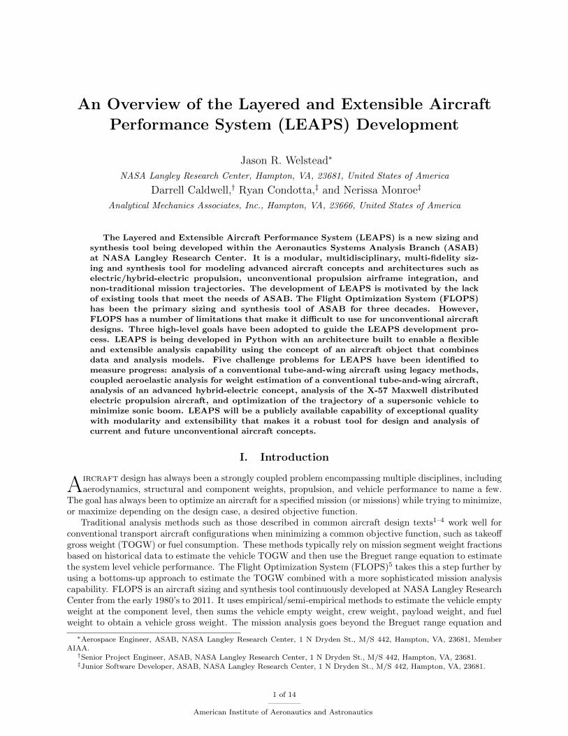
An Overview of the Layered and Extensible Aircraft
Performance System (LEAPS) Development
Jason R. Welstead∗
NASA Langley Research Center, Hampton, VA, 23681, United States of America
Darrell Caldwell,† Ryan Condotta,‡ and Nerissa Monroe‡
Analytical Mechanics Associates, Inc., Hampton, VA, 23666, United States of America
The Layered and Extensible Aircraft Performance System (LEAPS) is a new sizing andsynthesis tool being developed within the Aeronautics Systems Analysis Branch (ASAB)at NASA Langley Research Center. It is a modular, multidisciplinary, multi-fidelity siz-ing and synthesis tool for modeling advanced aircraft concepts and architectures such aselectric/hybrid-electric propulsion, unconventional propulsion airframe integration, andnon-traditional mission trajectories. The development of LEAPS is motivated by the lackof existing tools that meet the needs of ASAB. The Flight Optimization System (FLOPS)has been the primary sizing and synthesis tool of ASAB for three decades. However,FLOPS has a number of limitations that make it difficult to use for unconventional aircraftdesigns. Three high-level goals have been adopted to guide the LEAPS development pro-cess. LEAPS is being developed in Python with an architecture built to enable a flexibleand extensible analysis capability using the concept of an aircraft object that combinesdata and analysis models. Five challenge problems for LEAPS have been identified tomeasure progress: analysis of a conventional tube-and-wing aircraft using legacy methods,coupled aeroelastic analysis for weight estimation of a conventional tube-and-wing aircraft,analysis of an advanced hybrid-electric concept, analysis of the X-57 Maxwell distributedelectric propulsion aircraft, and optimization of the trajectory of a supersonic vehicle tominimize sonic boom. LEAPS will be a publicly available capability of exceptional qualitywith modularity and extensibility that makes it a robust tool for design and analysis ofcurrent and future unconventional aircraft concepts.
I. Introduction
Aircraft design has always been a strongly coupled problem encompassing multiple disciplines, includingaerodynamics, structural and component weights, propulsion, and vehicle performance to name a few.
The goal has always been to optimize an aircraft for a specified mission (or missions) while trying to minimize,or maximize depending on the design case, a desired objective function.
Traditional analysis methods such as those described in common aircraft design texts1–4 work well forconventional transport aircraft configurations when minimizing a common objective function, such as takeoffgross weight (TOGW) or fuel consumption. These methods typically rely on mission segment weight fractionsbased on historical data to estimate the vehicle TOGW and then use the Breguet range equation to estimatethe system level vehicle performance. The Flight Optimization System (FLOPS)5 takes this a step further byusing a bottoms-up approach to estimate the TOGW combined with a more sophisticated mission analysiscapability. FLOPS is an aircraft sizing and synthesis tool continuously developed at NASA Langley ResearchCenter from the early 1980’s to 2011. It uses empirical/semi-empirical methods to estimate the vehicle emptyweight at the component level, then sums the vehicle empty weight, crew weight, payload weight, and fuelweight to obtain a vehicle gross weight. The mission analysis goes beyond the Breguet range equation and
∗Aerospace Engineer, ASAB, NASA Langley Research Center, 1 N Dryden St., M/S 442, Hampton, VA, 23681, MemberAIAA.†Senior Project Engineer, ASAB, NASA Langley Research Center, 1 N Dryden St., M/S 442, Hampton, VA, 23681.‡Junior Software Developer, ASAB, NASA Langley Research Center, 1 N Dryden St., M/S 442, Hampton, VA, 23681.
1 of 14
American Institute of Aeronautics and Astronautics

evaluates a complete mission in a series of user-specified mission segments using the energy method firstpublished by Rutowski in 1954.6 Each segment can be optimized to a given objective or combination ofobjectives such as minimum time-to-climb, constant Mach with optimum altitude for specific range, etc.
As demands for improving aircraft environmental performance continue to increase, it will be difficult fortube-and-wing aircraft to meet the aggressive goals of reduced environmental impacts. This is resulting ina deviation from the conventional tube-and-wing configuration to a broad range of potential unconventionalconcepts for commercial transports of various sizes. Examples of ultra-efficient subsonic transport conceptsNASA is exploring with industry include double-bubble lifting fuselage, blended-wing-body, truss-bracedwing, and hybrid-wing-body with overwing nacelles. The list of unconventional concepts grows dramaticallywhen electric, hybrid-electric, and turboelectric propulsion architectures are included such as the NASAX-57 Maxwell X-plane.
These concepts present many challenges to legacy sizing and synthesis tools such as FLOPS, but thesechallenges are not unique to NASA. Development of new tools has become increasingly active across theaircraft conceptual design field as it has been broadly recognized that the current advanced aircraft conceptshave deviated sufficiently far from the empirical databases that they can no longer be relied upon to provideaccurate predictions for aircraft weights, aerodynamics, propulsion, and performance. The advanced conceptshave also become increasingly coupled across multiple disciplines, for example tighter propulsion-airframeintegration (PAI) with technologies such as boundary layer ingestion (BLI).
At the NASA Langley Research Center, the Aeronautics Systems Analysis Branch (ASAB) is developingthe Layered and Extensible Aircraft Performance System (LEAPS) as the next generation sizing and synthesistool to replace FLOPS. Formal software development began in Fall 2016, with background research andconcept exploration beginning in Fall 2014. Written in Python 3.x, LEAPS is being designed as a highlyflexible, modular tool that enables the analysis of not only the current portfolio of advanced aircraft concepts,but also the next generation of advanced concepts on the horizon with as-of-yet unknown technologies.A strong focus is being placed on the tool usability while also providing a means to easily extend themethodology through custom analyses. The user will be able to choose from different levels of fidelity withinan analysis model, utilizing low-order analyses where appropriate and selectively utilizing high-order analyseswhere needed. This paper is focused on providing an overview of LEAPS and describing the long term visionfor this new analysis capability.
A detailed discussion of the background and motivation for developing LEAPS, rather than adopting otheravailable tools, is presented in Section II. The goals and objectives that guide the fundamental developmentof LEAPS are discussed in Section III. The envisioned LEAPS architecture and current development isdescribed in Section IV. Some of the identified challenge problems and required capabilities are discussedin Section V. The paper concludes with a summary of the LEAPS development and some final thoughtsin Section VI. This paper is written in conjunction with two companion papers that describe some of thebasic low-order methodologies being integrated into LEAPS: weight estimation7 and mission analysis,8 whichbuilds upon Ref. 9.
II. Background and Motivation
Since the mid-1980’s the Flight Optimization System (FLOPS) has been the workhorse sizing and synthe-sis conceptual design tool used for NASA Langley aircraft systems analysis studies. A monolithic FORTRANcode, the tool was continuously enhanced by the lead developer, Arnie McCullers, through version 8.2, whichwas released for government use in 2011. Since this time, the tool has been nearly stagnant with the ex-ception of minor bug fixes. In 2016, a publicly available version was released and denoted FLOPS 9.0. Thegreatest strength of FLOPS has been its extreme versatility; nearly every component of the analysis can betuned, giving users the ability to explore the design space, validate a model to known data, and performsensitivity and trade studies. This capability has been the greatest contributor to the longevity of FLOPS,making it a tool used throughout industry, academia, and government organizations. Additionally, the sametool was capable of analyzing subsonic tube-and-wing transports, blended-wing-body subsonic transports,supersonic transports, and fighter aircraft.
Unfortunately, FLOPS has reached the end of its operational capability given the previously describedadvanced concepts that have risen to prominence in recent years. Advances in electric propulsion, bothas a power source and electrical system architecture, have been increasingly difficult to model using theFLOPS software. Recent analyses have been successful through the use of integration frameworks, such
2 of 14
American Institute of Aeronautics and Astronautics

as ModelCenter and OpenMDAO, where FLOPS has been manipulated to perform the required analyses.Examples include setting the engine thrust specific fuel consumption (TSFC) to nearly zero to simulate abattery-powered aircraft, performing various analyses outside of FLOPS and applying the applicable over-rides, and using outdated data columns in the FLOPS output in conjunction with a convergence loop inthe integrated analysis framework to achieve a desired analysis. Although these workarounds were sufficientat the time, it has reached the point where more manipulations than analyses are performed in order forFLOPS to generate the desired output.
The greatest limitations of FLOPS lie within the fundamental assumptions that are applied to the anal-yses. The fundamental assumptions include: 1) fuel is consumed during the mission, 2) the aerodynamiccharacteristics are only a function of Mach number, altitude, and lift coefficient, 3) the vehicle is a pointmass with a single degree of freedom (energy altitude), and 4) only a single propulsion type (fuel or elec-tric) can be used during any mission segment. The mission analysis is no longer capable of capturing theactive design constraints and system sensitivities that are shaping the advanced concept design space beingexplored today. The FLOPS aerodynamic analysis insufficiently captures the propulsion-airframe couplingutilized by recent advanced concepts where the vehicle aerodynamic performance is a function of propulsionsystem performance (throttle setting). Current state-of-the-art commercial transport aircraft fall outsidethe FLOPS empirical weight database causing the weight estimation routine to inaccurately capture trendsand sensitivities. These internal analyses required significant enhancement to improve the modeling of un-conventional configurations. It is because of these limitations that a requirement for a new mission analysisand synthesis capability has been identified.
To address the shortcomings of these legacy aircraft design tools, an internal NASA team was establishedto chart a path forward to bridge gaps in analysis required for robust synthesis of unconventional aircraftconfigurations, including those with electric/hybrid-electric propulsion system architectures. Instead of im-mediately embarking on a new tool development, a survey of developed conceptual design and analysistools was conducted to understand the established and new state-of-the-art approaches. With the aid of aNASA-funded study at the Georgia Institute of Technology, twenty-two conceptual design tools and softwaresuites were identified while acknowledging that there exist even more unidentified. Although the aircraftconceptual design community is relatively small, every organization appears to have their own preferredanalysis tools and methods. The identified tools included: Environmental Design Space (EDS),10 AircraftPerformance Program (APP)a, Advanced Aircraft Analysis (AAA)b, Project Interactive ANalysis and Opti-mization (Piano)c, Pacelab Aircraft Preliminary Design (PacelabAPD),11 Aircraft Design Software (ADS)d,FLight OPtimization System (FLOPS),5 AirCraft Synthesis (ACS)e, Transport Aircraft System OPTimiza-tion (TASOPT),12 Program for Aircraft Synthesis Studies (PASS),13 Stanford University Aerospace VehicleEnvironment (SUAVE),14–18 Preliminary Aircraft Design and Optimization (PrADO),19 Airliner COncep-tual DEsign (ACODE),20 Boeing Mission Analysis Program (BMAP),21 Truss Braced Wing MultidisciplinaryOptimization Design Environment,22 Aircraft Engine Design System Analysis Software (AEDsys)f, RDSg,Nicolai’s Sizing Programh, VAMPzero,23 MachUpi, Propulsion Airframe iNTegration for Hybrid ElectricResearch (PANTHER), Aircraft Preliminary Sizing Tool (PreSTo)j, and the Computational Research andEngineering for Acquisition Tools and Environments – Air Vehicles project (CREATE-AV) DaVinci.24–28
Many of the identified conceptual design tools rely on regression analyses and/or historical correlations toincrementally improve upon previous designs for similar aircraft configurations and missions. Several toolsconsist of proprietary methods and are not easily modified or enhanced. Tools such as BMAP and DaVinciare not available due to being commercial proprietary or limited government release, neither of which fosterscommunity collaboration.
SUAVE and TASOPT were explored in detail due to their recent development and broad availability.SUAVE is a Python-based open-source environment that enables multi-disciplinary and multi-fidelity analysisof advanced concepts. It is both a framework and a mission and performance analysis tool that is highly
ahttp://www.darcorp.com/Software/app/bhttp://www.darcorp.com/Software/AAA/chttp://www.piano.aero/dhttp://www.oad.aero/ehttp://www.avidaerospace.com/software/avid-acs/fhttps://www.aircraftenginedesign.com/custom1.html2.htmlghttp://www.aircraftdesign.com/rdspro.htmlhhttp://www.dept.aoe.vt.edu/~mason/Mason_f/MRsoft.html#Nicolaiihttps://www.blucraft.com/machup/jhttp://www.fzt.haw-hamburg.de/pers/Scholz/PreSTo.html
3 of 14
American Institute of Aeronautics and Astronautics

flexible, designed to analyze a broad range of missions and vehicle architectures. Recently demonstrated inRef. (16) was the coupling of OpenVSP, Gmsh, and SU2, an open-source flow solver developed at StanfordUniversity, for the analysis of a conventional tube-and-wing transport, a blended-wing-body transport, and asupersonic transport. The framework was used to generate a surrogate aerodynamic model for use in missionanalysis that is informed by high-order aerodynamic analysis.
A complex mission can easily be set up in SUAVE as a series of segments, but segments such as climband descent cannot be easily optimized for minimum time or fuel, a common practice in conceptual designmission modeling. Additionally, the rate-of-climb, velocity, and altitude must be specified. However, itis often useful to optimize the top-of-climb altitude to maximize the cruise performance, subject to anexcess power constraint on the propulsion system. The SUAVE architecture enables the analysis of bothconventional and unconventional vehicles through its analysis flexibility, and the user is able to modify thesource code as required without having to recompile. However, leveraging this capability requires the user tohave a strong familiarity with the source code and the interactions of the various components and libraries.Another limitation is the lack of sufficient documentation (at the time of evaluation) and the large numberof variables and classes that must be appropriately connected to obtain meaningful results. Finally, thecomputational expense of evaluating a mission that requires an iterative solution, such as determining theaircraft TOGW for a specific mission, is excessively high. This becomes a limiting factor when performinga large optimization, trade study, or design of experiments (DoE).
Transport Aircraft System Optimization (TASOPT) is an analysis tool developed at the MassachusettsInstitute of Technology that couples the analysis and optimization of an aircraft with the analysis andoptimization of a turbine engine.12 This provides a closely coupled airframe and engine design and analysis,leading to both being fully optimized simultaneously rather than two suboptimal designs stitched together.TASOPT is especially strong in the evaluation of concepts that include boundary layer ingestion, a technologythat relies upon synergistic propulsion-airframe integration to achieve a system level performance benefit.TASOPT uses fundamental physics-based methodologies for much of the vehicle analysis while trying tominimize the use of correlation and empirical-based relations.
A drawback of TASOPT is that the tool was designed to always optimize the vehicle for a specifiedmission. This creates issues when performing an independent assessment of a concept that has alreadybeen sized. The allowable mission definition lacks flexibility, which proves problematic for electric/hybrid-electric concepts. TASOPT was written as a monolithic FORTRAN code, which means that the tool hasthe benefits of the improved execution time of a compiled code, but it is challenging modify or completelyreplace analyses. This reduced flexibility limits the tool’s capability to analyze a broad range of vehicle typesand architectures without significant modification similar to the ASAB tool, FLOPS. The input file requiresdetailed information not always available early in the conceptual design process, such as component materialproperties and temperature limits. There is an extensive theory manual for TASOPT which helps the userunderstand the methodologies implemented in TASOPT, but the lack of a user’s manual makes it extremelydifficult to create an input file from scratch or deviate significantly from an example input file.
Each tool was used to model the Central Reference Aircraft data System (CeRAS),29 a conventional tube-and-wing aircraft model based on the A320 used to baseline modeling and analysis tools. After evaluatingboth TASOPT and SUAVE, it was determined that the best solution for ASAB was to develop a new,in-house aircraft conceptual design software. One option considered was to leverage the currently availablesoftware as a starting point, but it was not desired to have multiple versions of TASOPT or SUAVE. Therealso existed within ASAB a strong desire to have complete control over the software development as opposedto contributing to a non-NASA controlled open source development such as SUAVE.
The motivation for developing LEAPS is to first and foremost meet the needs of our primary customer,NASA. These needs include being able to design and evaluate a broad range of aircraft concepts and propul-sion system architectures. The high degree of coupling between airframe and propulsion technologies infuture advanced concepts requires new, innovative analysis techniques that are suitable for conceptual de-sign but can be informed by higher fidelity analyses. Although the focus is the design of advanced aircraftconcepts, the capability to independently evaluate external concepts or as-built aircraft is absolutely requiredfor ASAB to act as an independent broker for NASA decision makers. FLOPS excelled at performing anindependent analysis, while allowing the user to “tweak” the underlying analyses through the flexible use ofinput variables to account for various technology assumptions. Moving forward, it is desired to retain thiscapability while adding enhanced flexibility for a modular analysis tool that enables multidisciplinary andmulti-fidelity analysis.
4 of 14
American Institute of Aeronautics and Astronautics

It is also desired to reach out in a collaborative manner to address some of the challenges of non-NASAcustomers such as the Department of Defense or academia. With the ever changing landscape of advancedconcepts and technologies, active development of new analysis methods and techniques will ensure a continuedcapability for analyzing the state-of-the-art. Any new analysis methods developed as part of LEAPS shouldbe shared with the aircraft design community. This collaborative environment is highly desired as part ofthe NASA push to release internally developed software to the public domain. To foster this collaboration,LEAPS will be released as Publicly Available including all source code and user documentation.
Even though LEAPS is being developed as a completely new software, this does not imply that legacymethods are obsolete or externally developed methods cannot be integrated. The desire is to leverageanalysis techniques and methodologies as much as feasible without compromising the ability to publiclyrelease. Particular emphasis is being placed on developing an operational tool, not just a research tool,that provides an exceptional user experience and robust analysis with informed feedback. LEAPS should beusable by all aircraft designers and not just a limited set of researchers that actively develop the code.
In summary, the motivations for developing LEAPS are 1) a lack of tools that meet internal customerneeds for the analysis of advanced aircraft concepts and propulsion architectures using multidisciplinary andmulti-fidelity analyses, 2) a desire to collaborate on aircraft concepts and analysis methods in the publicdomain, 3) the lack of software with robust error checking, informative exception messages, and completeuser and theory documentation, and 4) the inability to easily modify, enhance, or extend analyses as newtechnologies and computational capabilities are developed.
III. Goals and Objectives
A set of high-level goals were established to provide a unified vision for the LEAPS tool development.These goals provide the overarching guidelines for establishing development objectives for the software ar-chitecture, analysis models, and tool execution. The high-level goals are:
1. develop a modular, multidisciplinary, multi-fidelity aircraft design and performance software tool;
2. create an aircraft design and analysis tool of exceptional quality and performance; and
3. enable the ease of distribution to the aeronautical community.
The first goal is quite simple in its description; design an analysis tool capable of performing the breadthof analyses required by NASA systems analysts using a range of analysis fidelities. LEAPS is not an effort todrive high-order analysis tools to all aspects of aircraft conceptual and preliminary design. Instead, the focusof LEAPS is to enable the right analysis for the right job at the right time. This thinking allows the user tochoose which analysis fidelity to use while understanding the trade between computational time and analysisorder. This goal drives the development to enable a flexible analysis capability for the next generation ofsizing and synthesis of advanced aircraft concepts. The objectives that support the first high-level goal are:
• support analysis of a broad range of aircraft, including: transports to fighters, tube-and-wing to blendedwing body, and jet fuel to all electric propulsion;
• incorporate an energy agnostic framework allowing the analysis of a broad range of traditional andfuture power systems, energy storage systems, and energy harvesting systems;
• support multi-order, fully-coupled analysis and simulation built centrally around a mission performancecore; and
• be capable of providing the relevant information to support the latest tools for optimization, sensitivityanalysis, and design of experiments.
The second high-level goal places an emphasis on delivering a high quality software. Often, analysistools are developed in direct response to a research question that requires a timely answer. As such, ananalysis tool is hastily developed that answers the research question but is highly restricted in its capabilityand usability; usually, only the tool developer is able to glean usable answers from the software. This isreactionary tool development and is often necessary to meet organizational research demands. LEAPS isbeing developed as a proactive tool development. An analysis capability gap has been identified, but nospecific research question is being answered. As a proactive tool development, special emphasis has been
5 of 14
American Institute of Aeronautics and Astronautics

placed on utilizing standard software development practices, such as enforced version control, code reviews,unit testing, and simultaneous documentation and development, to deliver a software of exceptional quality.This approach is enabled by having a team of both exceptional aerospace engineers and software engineersworking closely together.
A positive user experience drives the architecture development to ensure that the software is both capableand useful. As capability grows, the usability can decrease or be subject to an extreme learning curve fornew users. Through careful user-interface design, the goal is to provide a highly capable software whiledecreasing the learning curve for new users. A major aspect of this is informative feedback from the tool,such as clear exception messages that provide direction to resolution, status updates, detailed feedback uponrequest (verbose), and clear output data that is easy to interpret and clearly labeled (with units). Whensuccessfully implemented, LEAPS will be a high-quality tool with significant capability and a positive userexperience.
As was mentioned previously, there is a trade between analysis fidelity and computational cost. The userultimately makes this trade in their analysis setup. However, there is also a trade between computationalspeed and ease of development when choosing a programming language. A strength of FLOPS is its abilityto perform a complex analysis—including optimizing mission trajectories—in approximately one second. Ifthe FLOPS methodology was identically implemented in Python, the analysis time would be measurablylonger. No emphasis has been placed on hitting a target analysis time, but instead an emphasis has beenplaced on having sufficient computational performance such that the user can obtain usable information ina timely manner to answer his/her research questions. The objectives that summarize the second high-levelgoal are:
• develop LEAPS using standard software engineering development practices;
• be of a modular design with a flexible architecture; and
• provide an exceptional user experience in terms of stability, reliability, and informed exception mes-sages.
The final high-level goal for LEAPS focuses on the strong desire to foster collaboration within the aircraftconceptual design community. The NASA open source initiative has placed an emphasis on distributing toolsand capabilities developed through tax-payer dollars to the research community. LEAPS will not be releasedas open source. Instead, LEAPS will be released as publicly available, which is only subtly different, toenable collaboration on methods, analysis techniques, and results. The supporting objective for this finalgoal is clear and concise: develop LEAPS with procedures and practices that enable easy distribution ofmethods and software to the aeronautics community.
IV. Software Architecture
The LEAPS software architecture was designed to achieve the high-level goals and objectives describedin Section III. In addition to the goals and objectives, experiences solicited from a broad range of FLOPSusers have shaped the LEAPS architecture design.
A. User Stories
In order to maximize the quality of the user experience, multiple FLOPS users were interviewed togain their insights and experiences. These user stories directly influenced the LEAPS architecture designand development. Those interviewed included newer users, users with moderate experience, and experts inorder to obtain a broad range of feedback and experiences, all of which could be captured in the LEAPSdevelopment.
In these user stories certain key features were consistently mentioned. Well-liked FLOPS features weresuggested for LEAPS, one being the short computation time to run a single analysis case. FLOPS canexecute a complete analysis in approximately one second. LEAPS will be designed so that execution time issufficiently fast with specific care given to profile the code and eliminate unnecessarily excessive computationtime. Another positive FLOPS feature identified was the assumed default values for input variables. Havinggood default values for most user inputs enables a rather complicated FLOPS analysis with a very shortinput file. The user can increase the fidelity of the input and the analysis as they gain more information
6 of 14
American Institute of Aeronautics and Astronautics

about the design, but they do not have to jump from a zero solution state to a full solution state. Anextensive override capability allows users to modify internally computed values with either an absolute valueor scalar multiplier. This is useful when modifying an internal analysis to match data produced by anexternal analysis, such as a finite element model.
Also, the highly formatted text output, including the input echo, was viewed very positively by mostusers. This enables the easy use of differencing tools, parsing the output for feeding other analysis orframeworks, and being able to easily use the features of advanced text editors.
The major complaint of FLOPS users centers on the lack of exceptions and warnings. FLOPS in manyways does not exit gracefully and thus provides the user little to no insight as to why the execution failed.If convergence loops do not complete, there is little or no warning. Also, it was found that there is a lack ofrobust and clear error handling. Errors and warnings are intermixed in the output, which is of sizable length,and they can be easily missed when reviewing the output. Numerous other minor issues were identified, butfor conciseness, only these major themes that were influential in the LEAPS software architecture have beenhighlighted.
B. Architecture Design
Leveraging the FLOPS user experiences, the LEAPS architecture was designed to present four generaluser interfaces: command line, input file, output stream, and log files. The command line allows the user torequest help, specific modes and/or analyses, or optional data. The command line also provides the capabilityto both specify an input file and, for the purpose of capturing the output stream, a output file path. Theinput file allows the user to request analyses and specify related data and/or notes for requested analyses. Itallows the user to logically separate data according to configurations, aircraft components, etc., for analysis.The output stream provides the user with the results of requested analyses as text. By default, LEAPSgenerates a log file that provides the user with regular status updates and any requested optional data. Thisinformation allows the user to determine if LEAPS is performing as expected. These user interfaces rununder a simple concept of execution, which is divided into the four phases of startup, setup, update, andreport. The startup and setup phases initialize variables and do preliminary calculations. The update phaseperforms the bulk of the calculations. The report phase outputs the results of the calculations.The flow ofthe concept of execution is shown in Fig. 1.
Overview Startup Setup
Update
Report
Command Line Input
Input File
Execute
Analysis Data
Execute
Analysis Complete?
YesNo
Figure 1. LEAPS concept of execution.
LEAPS data exchange is based on the concept of an “aircraft” object and the user-specified analysismodels. An “aircraft” object is composed of modeled physical behaviors and supporting data sets logicallygrouped together in components. The model requested by the user dictates the analyses and required input
7 of 14
American Institute of Aeronautics and Astronautics

and derived data. LEAPS supports at a minimum five model concepts per aircraft:
• The energy model calculates thrust production and power consumption. Thrust and power are includedhere to model propulsion systems of all types. Aircraft can use mass exchange, internal combustion,electrical power, or some combination of one or more propulsion types, to produce thrust. Power forother systems may be a byproduct of thrust production. Additional energy storage may be availableand/or required for those same systems or propulsion.
• The weights model calculates the dynamic weights of the aircraft and its subsystems as a function ofthe mission. It also calculates the static (constant with time) weights of an aircraft and its subsystems.
• The atmosphere model defines density, temperature, and speed of sound as a function of altitude. Thedefault atmosphere model is for Earth. Simulating flight conditions on Earth using a different fidelitymodel or on another planet can be achieved by specifying an alternative atmosphere model that isprovided by the user.
• The aerodynamics model calculates lift and drag properties of an aircraft based on thrust, weight,an atmosphere model, and the current geometric configuration. Additional aerodynamic propertiessuch as moments can be calculated as required via higher analysis fidelity when using a more complexmission model.
• The mission model manages the different mission segments from takeoff through landing. Analyses canfocus on only one segment, or can focus on the following combinations: takeoff and flight, flight andlanding, or takeoff, flight, and landing. Flight is defined as a series of segments (climb, cruise, descent,turn, loiter, etc.) for lower level analysis and a full flight trajectory simulation for higher level analysis.Maneuvers may be included as part of the flight phase of a mission.
Figure 2. Various analysis levels of LEAPSmodels.
Each model consists of a set of layers, as shown inFig. 2, that represent various analysis levels dependentupon user input. Higher Levels are associated with in-creasing analysis order and complexity within a model.Higher analysis Levels require increased user input andinput fidelity. Each model represents a customizationpoint. End users are permitted to use and/or write re-placement models as desired using a Model Package In-terface. Each model package shall provide its own setof model specific handlers. Handlers add componentsto an “aircraft” object by reading input data streams,and they write “aircraft” object components to outputdata streams. The handlers are instantiated and invokedas needed through a common package interface, as suchhandlers are an internal implementation detail. Thisgives each model package maintainer the option to im-plement appropriate handlers as needed.
LEAPS’ extensible nature allows the user to runanalyses in a multitude of ways. The user can customizeLEAPS by adding new models and/or removing default models for an analysis. When creating new models,client code will use the LEAPS Model Package Interface, which is a set of required functions implementedin a client model or package. From this interface, the user has the ability to replace any of the models withtheir own implementation.
LEAPS can also be externally driven by another program. This means that LEAPS, whether it be asingle model such as weights or the entire LEAPS core, can be plugged into another external driver andexecuted. The LEAPS core, as represented in Fig. 3, is a combination of the input interface, the outputinterface, and the models of LEAPS. These are the core components necessary to run LEAPS. The abilityto be externally driven enables the user to pull the key components, or the entirety, of LEAPS that theyare interested in and perform numerical techniques and operations such as optimization. The separation ofnumerical techniques such as optimization from LEAPS is to enable the user to run their desired techniques
8 of 14
American Institute of Aeronautics and Astronautics

and not limit them to only a LEAPS provided capability. For this to occur, the interface between the externaldriver and LEAPS must be created. The combination of customizing and selecting models provides the userwith a capability to use aspects of LEAPS they find useful, while not limiting them to features provided.The multitude of interfaces, as shown in Fig. 3, create an extensible and flexible tool.
Figure 3. LEAPS input/output interfaces.
C. LEAPS Input File Structure
The LEAPS input file uses a configuration file format (.ini). This file format was selected over otherformats such as XML, CSV, and JSON. The Python package library provides support for INI files thatis straightforward and concise, and the file structure and organization is simple and easy to understand.This file is separated into comments, sections, and properties. The comments are used for denoting non-initialization information and are ignored by the LEAPS parser. The sections and the properties captureinitialization data. In Fig. 4 a comparison of the FLOPS input file and LEAPS input file is shown. Afew differences indicated are the structure, names, and notes aspects. As shown in Fig. 4, the input file isorganized efficiently according to component structure and verbose terminology. It even allows the notes tobe organized according to the variable with which they are associated. These advantages allow the user toquickly organize an input file and run an analysis with ease.
The LEAPS input file uses an initialization file format (.ini). The initialization file format was selected to be the best for several reasons. First, the ini file has a python package library support that is straight forward and concise. The second reason is that its structure and organization is simple and quick to follow. This file is separated into comments, sections, and properties. The comments are used for denoting non initialization information and ignored by the LEAPS parser. The sections and the properties capture initialization data. In Figure~ref{fig:} a comparison of the FLOPS input file and LEAPS input file is shown. The few of the differences shown are the structural, names, and notes aspect. From Figure~ref{fig:} the input file is organized efficiently according to component structure and verbose terminology. It evens allows the notes to be organized according to the variable they are associated with. These advantages allow the user to quickly organize an input file to run an analysis with ease.
Structure
Names
Notes
Figure 4. Comparison of the legacy FLOPS input file with a namelist-based organization andthe new LEAPS input file using the initialization file format.
9 of 14
American Institute of Aeronautics and Astronautics

V. Description of Identified Challenge Problems
Any new tool that replaces a legacy tool must first show that it can perform the analysis of the legacytool. In this case, LEAPS is replacing FLOPS which excelled at accurately modeling tube-and-wing aircraftwhen compared to published data. LEAPS must be able to replicate this capability since many advancedconcepts are compared to an equal technology conventional tube-and-wing baseline aircraft. The analysismethods used in the evaluation of conventional aircraft still retain validity, and so these legacy methods arebeing utilized as much as possible in LEAPS and expanded as required. A set of challenge problems havebeen identified to guide the LEAPS development, where each problem requires enhanced capability to besolved. When LEAPS is capable of handling the challenge problems, it will have significant capability farbeyond the current ASAB legacy tools.
The first challenge problem is the analysis of a conventional tube-and-wing aircraft that leverages legacymethods and combines them with the new LEAPS architecture and mission performance analysis (see Ref. 8).These results will be directly compared to a FLOPS analysis as there is high confidence in the quality ofthe FLOPS analysis in this case. The goal is not to replicate the results of FLOPS—there should be minordisagreements due to changes in methodology—but to instead show that the analysis results are consistentbetween the tools and the differences are clearly understood. This first challenge problem is focused onverification and validation of the LEAPS methods and architecture while obtaining feedback on the userexperience.
The second challenge problem builds upon the first challenge problem by incorporating a coupled aeroe-lastic analysis on a tube-and-wing configuration. Technology improvements in both aerodynamics and struc-tures are enabling aircraft to improve vehicle level performance by increasing wing span and aspect ratio. Forspan constrained aircraft, such as single-aisle aircraft complying with Class C airport operations, the span isfixed, but the aspect ratio continues to incrementally increase. The higher wing aspect ratios and spans havesufficiently deviated from the legacy database such that empirical wing weight estimates are not capturingthe appropriate trends. Cantilevered wings are transitioning from being stress constrained to aeroelasticconstrained (tip deflection and flutter). This challenge problem will leverage an extension of LEAPS for acoupled aero-structural analysis to improve the structural weight estimates of the primary structure. Thechallenge lies in sufficiently capturing the static and dynamic aeroelastic constraints without compromisingthe ability to perform an entire analysis in a timely manner.
Figure 5. Artistic rendering of the PEGASUSconcept.30
The third challenge problem is the design andanalysis of the advanced aircraft concept PEGA-SUS (Parallel Electric-Gas Architecture with Syn-ergistic Utilization Scheme).30 The PEGASUS con-cept, shown in Fig. 5, is a regional aircraft designedspecifically to revitalize the short-haul market byleveraging hybrid-electric technologies and synergis-tic PAI to minimize the vehicle operating cost. Mul-tiple propulsors are used on this concept includinginboard electric propulsors, turbine-electric wingtippropulsors, and an unducted tailcone BLI propul-sor. This concept utilizes multiple unique propul-sors, an electric/hybrid-electric architecture that forshort missions can operate on batteries alone, andflexibility in the split of electric energy versus fuelenergy. Analysis of this concept requires significant
capability enhancement beyond legacy tools to account for multiple propulsor models with individual throt-tling control throughout the mission, tracking of energy instead of fuel to converge on total energy usage,and robust PAI modeling. LEAPS must also be driven by an external driver to optimize the electric split ofthe aircraft architecture.
The fourth identified challenge problem is the analysis of the X-57 Maxwell aircraft. The X-57 is an all-electric manned demonstrator with distributed propulsors along the wing leading edge and cruise propellerson the wingtips, as is shown in Fig. 6(a). Analyzing this aircraft will exercise the new energy agnosticarchitecture for calculating the all-electric mission performance, but a greater challenge lies in capturingthe highly throttle dependent aerodynamic effects. The success of the X-57 concept lies in its ability tocapitalize on the distributed propeller aero-propulsive coupling, that in the simplest description, acts like a
10 of 14
American Institute of Aeronautics and Astronautics

(a) X-57 Maxwell electric aircraft with leading edge distributedpropulsion.31,32
(b) Rendering of the Quiet Supersonic Transport (QueSST).k
Figure 6. NASA X-plane concepts identified as LEAPS challenge problems.
high-lift system. Additional complexity is added to the architecture by also leveraging synergistic PAI withthe wingtip propellers. The expectation is that flight test data from the demonstrator will be available toaid in performing this analysis.
The final identified challenge problem is to perform a mission analysis for a supersonic vehicle in whichthe trajectory has been optimized to minimize a boom propagation signal. To perform this analysis aseries of CFD solutions will need to be generated such that a surrogate model can be used for the off-body pressure profiles. This is assuming that it is infeasible to compute off-body pressure profiles duringanalysis execution due to prohibitively long execution time, but in reality that could be done with enoughcomputational resources and patience. LEAPS will have to be extended to include the surrogate model,a sonic boom propagation tool such as sBOOM,33 and a user custom objective function for the missionsegment or segments being optimized with respect to the boom signature. An example configuration to usefor this challenge problem is the Quiet Supersonic Transport (QueSST) shown in Fig. 6(b).
VI. Summary
The Layered and Extensible Aircraft Performance Systems (LEAPS) is being developed as the nextgeneration aircraft sizing and synthesis tool for the Aeronautics Systems Analysis Branch (ASAB) at NASALangley Research Center, replacing the legacy Flight Optimization System (FLOPS) software. This tool isbeing proactively developed to address the current and future challenges in the modeling of advanced aircraftconcepts and technologies. The development is being accomplished through a modular, multidisciplinary,multi-fidelity analysis capability with an architecture intentionally designed to be flexible and extensible. Themotivation for developing this new tool was to meet the needs of ASAB, close the current analysis capabilitygaps, foster collaboration in methods development and the analysis of advanced concepts, and develop asoftware that provides a positive user experience and is capable of being enhanced for years to come. Thesemotivations for developing LEAPS were mapped directly into the high-level software development goals andobjectives. The software architecture design was described in detail in Section IV and has been developedto achieve the high-level goals. Finally, some long term challenge problems have been identified to providedevelopment direction for continued capability enhancement.
Acknowledgments
This research was funded by both the Transformational Tools and Technologies (TTT) Project, part ofthe Transformative Aeronautics Concepts Program (TACP), and the Advanced Air Transport Technologies(AATT) Project, part of the Advanced Air Vehicles Program (AAVP) within the NASA Aeronautics ResearchMission Directorate (ARMD).
khttps://www.nasa.gov/press-release/nasa-completes-milestone-toward-quieter-supersonic-x-plane
11 of 14
American Institute of Aeronautics and Astronautics

References
1 Raymer, D. P., Aircraft Design: A Conceptual Approach, 3rd ed., American Institute of Aeronautics andAstronautics, Reston, VA, 2006.
2 Nicolai, L. M. and Carichner, G. E., Fundamentals of Aircraft and Airship Design: Volume I , AIAAEducation Series, American Institute of Aeronautics and Astronautics, Reston, VA, 2010.
3 Roskam, J., Airplane Design, Pt. II , DARcorporation, Ottawa, KS, 1997.
4 Torenbeek, E., Synthesis of Subsonic Airplane Design, Delft University Press, Delft, Holland, 1982.
5 McCullers, L., “Aircraft Configuration Optimization Including Optimized Flight Profiles,” Proceedings ofthe Symposium on Recent Experiences in Multidisciplinary Analysis and Optimization, No. NASA CP-2327, 1984, pp. 395–412.
6 Rutowski, E. S., “Energy Approach to the General Aircraft Performance Problem,” Journal of the Aero-nautical Sciences, Vol. 21, No. 3, 1954, pp. 187–195.
7 Horvath, B. L. and Wells, D. P., “Aircraft Conceptual Design Weight Estimation Comparison to the FlightOptimization System Method,” AIAA Aerospace Sciences Meeting , American Institute of Aeronautics andAstronautics, 2018, (To Be Published).
8 Capristan, F. M. and Welstead, J. R., “An Energy-Based Low-Order Approach for Mission Analysisof Air Vehicles in LEAPS,” AIAA Aerospace Sciences Meeting , American Institute of Aeronautics andAstronautics, 2018, (To Be Published).
9 Capristan, F. M. and Welstead, J. R., “LEAPS: An Initial Assessment Towards a Multi-Order Approachto Air Vehicle Mission Analysis,” 18th AIAA/ISSMO Multidisciplinary Analysis and Optimization Confer-ence, American Institute of Aeronautics and Astronautics, Denver, CO, 2017, pp. 1–16, AIAA-2017-4325.
10 Kirby, M. R. and Mavris, D. N., “The Environmental Design Space,” 26th International Congress of theAeronautical Sciences, 2008, pp. 1–9.
11 Locatelli, D., Riggins, B., Schetz, J. A., Kapania, R. K., Robic, B., Leenaert, C., and Poquet, T., “AircraftConceptual Design: Tools Evaluation,” 14th AIAA Aviation Technology, Integration, and OperationsConference, American Institue of Aeronautics and Astronautics, Atlanta, GA, June 2014, pp. 1 – 38,AIAA-2014-2030.
12 Greitzer, E. M., et al., “N+3 Aircraft Concept Designs and Trade Studies, Final Report,” ContractorReport Volume II, National Aeronautics and Space Administration, 2010, NASA/CR-2010-216794.
13 Antoine, N. E., Aircraft Optimization for Minimal Environmental Impact , Ph.D. thesis, Stanford Univer-sity, August 2004.
14 Wendorff, A. D., Botero, E., and Alonso, J. J., “Comparing Different Off-the-Shelf Optimizers’ Perfor-mance in Conceptual Aircraft Design,” 17th AIAA/ISSMO Multidisciplinary Analysis and OptimizationConference, American Institute of Aeronautics and Astronautics, Washington, D.C., June 2016, pp. 1–14,AIAA-2016-3362.
15 Variyar, A., Economon, T. D., and Alonso, J. J., “Multifidelity Conceptual Design and Optimizationof Strut-Braced Wing Aircraft using Physics-Based Methods,” 54th AIAA Aerospace Sciences Meeting ,American Institue of Aeronautics and Astronautics, San Diego, CA, January 2016, pp. 1 – 13, AIAA-2016-2000.
16 MacDonald, T., Botero, E., Vegh, J. M., Variyar, A., Alonso, J. J., Orra, T. H., and Ilario da Silva,C. R., “SUAVE: An Open-Source Environment Enabling Unconventional Vehicle Designs through HigherFidelity,” 55th AIAA Aerospace Sciences Meeting , American Institute of Aeronautics and Astronautics,Grapevine, TX, January 2017, pp. 1–17, AIAA-2017-0234.
12 of 14
American Institute of Aeronautics and Astronautics

17 Botero, E., Wendorff, A. D., MacDonald, T., Variyar, A., Vegh, J. M., Lukaczyk, T., Alonso, J. J.,Orra, T. H., and Ilario da Silva, C. R., “SUAVE: An Open-Source Environment for Conceptual VehicleDesign and Optimization,” 54th AIAA Aerospace Sciences Meeting , American Institute of Aeronauticsand Astronautics, San Diego, CA, January 2016, pp. 1–17, AIAA-2016-1275.
18 Lukaczyk, T., Wendorff, A. D., Botero, E., MacDonald, T., Momose, T., Variyar, A., Vegh, J. M.,Colonno, M., Economon, T. D., Alonso, J. J., Orra, T. H., and Ilario da Silva, C., “SUAVE: An Open-Source Environment for Multi-Fidelity Conceptual Vehicle Design,” 16th AIAA/ISSMO MultidisciplinaryAnalysis and Optimization Conference, American Institue of Aeronautics and Astronautics, Dallas, TX,June 2015, pp. 1 – 56, AIAA-2015-3087.
19 Strohmeyer, D. and Seubert, R., “Improvement of a Preliminary Design and Optimization Program for theEvaluation of Future Aircraft Projects,” 7th AIAA/USAF/NASA/ISSMO Symposium on MultidisciplinaryAnalysis and Optimization, American Institute of Aeronautics and Astronautics, 1998, pp. 1–8, AIAA-1998-4828.
20 Lefebvre, T., Schmollgruber, P., Blondeau, C., and Carrier, G., “Aircraft Conceptual Design in a Multi-Level, Multi-Fidelity, Multi-Disciplinary Optimization Process,” 28th International Congress of the Aero-nautical Sciences, International Congress of the Aeronautical Sciences, 2012, pp. 1–11.
21 Bradley, M. K. and Droney, C. K., “Subsonic Ultra Green Aircraft Research: Phase I Final Report,”Contractor Report NASA/CR-2011-216847, NASA Langley Research Center, Hampton, VA, April 2011.
22 Gur, O., Bhatia, M., Mason, W. H., Schetz, J. A., Kapania, R. K., and Nam, T., “Development ofFramework for Truss-Braced Wing Conceptual MDO,” 51st AIAA/ASME/ASCE/AHS/ASC Structures,Structural Dynamics, and Materials Conference, American Institute of Aeronautics and Astronautics,2010, pp. 1–32, AIAA-2010-2754.
23 Bohnke, D., Nagel, B., and Gollnick, V., “An Approach to Multi-fidelity in Conceptual Aircraft Design inDistributed Design Environments,” 2011 IEEE Aerospace Conference, 2011, pp. 1–10.
24 Livingston, J. W., “Aeronautical System Design and Physics-Based Simulation,” 55th AIAA AerospaceSciences Meeting , American Institute of Aeronautics and Astronautics, Grapevine, TX, 2017, pp. 1–11,AIAA-2017-1195.
25 Roth, G. L., Livingston, J. W., Blair, M., and Kolonay, R., “CREATE-AV DaVinic: ComputationallyBased Engineering for Conceptual Design,” 48th AIAA Aerospace Sciences Meeting , American Instituteof Aeronautics and Astronautics, Orlando, FL, 2010, pp. 1–17, AIAA-2010-1232.
26 Brooks, G. P., Livingston, J. W., Adamec, S., and McGough, W., “HPCMP CREATE-AV DaVinci 3.0and HPCMP CREATE-MG Capstone Integration,” 53rd AIAA Aerospace Sciences Meeting , AmericanInstitute of Aeronautics and Astronautics, Kissimmee, FL, 2015, pp. 1–17, AIAA-2015-1508.
27 Rooney, B. D., “The CREATE-DaVinci Power User Experience,” 52nd Aerospace Sciences Meeting , Amer-ican Institute of Aeronautics and Astronautics, National Harbor, MD, 2014, pp. 1–7, AIAA-2014-0921.
28 Post, D. E., Atwood, C. A., Newmeyer, K. P., Meakin, R. L., Vogelson, R. L., Hariharan, N., Morton,S., Livingston, J., D’Angelo, J. N., Dey, S., Gorski, J., Moyer, E. T., Mackenna, A., and Strawn, R.,“The CREATE Program: Design and Analysis Tools for DoD Weapon Systems,” 54th AIAA AerospaceSciences Meeting , American Institute of Aeronautics and Astronautics, San Diego, CA, 2016, pp. 1–17,AIAA-2016-0562.
29 Risse, K., Schafer, K., Schultke, F., and Stumpf, E., “Central Reference Aircraft data System (CeRAS)for research community,” CEAS Aeronautical Journal , Vol. 7, No. 1, 2016, pp. 121–133.
30 Antcliff, K. R. and Capristan, F. M., “Conceptual Design of the Parallel Electric-Gas Architecture withSynergistic Utilization Scheme (PEGASUS) Concept,” AIAA/ISSMO Multidisciplinary Analysis and Op-timization Conference, American Institute of Aeronautics and Astronautics, Denver, CO, June 2017, pp.1 – 15, AIAA-2017-4001.
13 of 14
American Institute of Aeronautics and Astronautics

31 Borer, N. K., Patterson, M. D., Viken, J. K., Moore, M. D., Clarke, S., Redifer, M. E., Christie, R. J.,Stoll, A. M., Dubois, A., Bevirt, J., Gibson, A. R., Foster, T. J., and Osterkamp, P. G., “Design andPerformance of the NASA SCEPTOR Distributed Electric Propulsion Flight Demonstrator,” 16th AIAAAviation Technology, Integration, and Operations Conference, American Institute of Aeronautics andAstronautics, Washington, D.C., 2016, pp. 1–20, AIAA-2016-3920.
32 Dubois, A., van der Geest, M., Bevirt, J., Clarke, S., Christie, R. J., and Borer, N. K., “Design of an ElectricPropulsion System for SCEPTOR’s Outboard Nacelle,” 16th AIAA Aviation Technology, Integration, andOperations Conference, American Institute of Aeronautics and Astronautics, Washington, D.C., 2016, pp.1–30, AIAA-2016-3925.
33 Rallabhandi, S. K., “Advanced Sonic Boom Prediction Using the Augmented Burgers Equation,” Journalof Aircraft , Vol. 48, No. 4, 2011, pp. 1245–1253.
14 of 14
American Institute of Aeronautics and Astronautics


![[MS-PEAP-Diff]: Protected Extensible Authentication ......Protected Extensible Authentication Protocol (PEAP)](https://img.pdfslide.us/doc/110x75/5f0eef6d7e708231d441aa24/ms-peap-diff-protected-extensible-authentication-protected-extensible.jpg)