Embed Size (px)
Citation preview

Southern African Pyrometallurgy 2006, Edited by R.T. Jones, South African Institute of Mining and Metallurgy, Johannesburg, 5-8 March 2006
63
An overview of PGM Smelting in Zimbabwe – Zimplats Operations
L. Mabiza Zimplats, Selous, Zimbabwe
Keywords: Pyrometallurgy, circular furnace, PGM, platinum, Peirce-Smith converter, Zimbabwe
Abstract – The Zimplats Smelter, located on the northern part of the Great Dyke, at the Selous Metallurgical Complex, is the only PGM smelter in Zimbabwe. Zimplats’ operations currently consist of the Ngezi Platinum Mine, which is a 1.5 Mt/a open-cast and 0.7 Mt/a underground mine, and a Concentrator and Smelter to which ore is transported 80 km by road. The final converter matte product is transported to Impala Refining Services in South Africa for refining and marketing.
The Zimplats Smelter operations consist of a concentrate filtration plant, a Drytech flash dryer, a modified Elkem / Hatch 13.5 MVA circular furnace, two 10’ x 15’ Peirce-Smith converters, and a matte granulation plant. The Zimplats smelter uses a three-field electrostatic precipitator, supplied by ELB-Brandt, for removal of particulates in the gas streams from both the converter and furnace.
Construction of the smelter commenced in 1995, under the BHP / Delta Gold of Australia joint venture. The furnace was lined mid-1996, and smelting operations commenced in 1997. Due to design challenges, the Elkem furnace was modified by Hatch in 1998, and the smelter had not reached full capacity when operations were suspended in 1999. Re-commissioning took place in January 2002.
INTRODUCTION The Zimplats Smelter at the Selous Metallurgical Complex (SMC) is the only PGM smelter in Zimbabwe. The Smelter is located on the northern part of the Great Dyke, 80 km south west of Harare, along the Harare-Bulawayo highway. The Zimplats operations begin at Ngezi Platinum Mine, which is a 1.5 Mt/a opencast and 0.7 Mt/a underground mine. The ore is then transported 80 km by road to SMC, and treated through the concentrator and smelter. The final converter matte product is then transported to Impala Refining Services in South Africa, for refining and marketing. The Zimplats Smelter operations consist of a concentrate filtration plant, a Drytech flash dryer, a modified Elkem / Hatch 13.5 MVA circular furnace, two 10’ x 15’ Peirce-Smith converters, and a matte granulation plant. The Zimplats smelter uses a three-field electrostatic precipitator, supplied by ELB-Brandt, for removal of particulates in the gas streams from both the converter and furnace.

64
Construction of the Smelter commenced in 1995, under the BHP / Delta Gold of Australia joint venture. The furnace was lined mid-1996, and smelting operations commenced in 1997. Due to design challenges, the Elkem furnace was modified by Hatch in 1998, and the smelter had not reached full capacity when operations were suspended in 1999. Each of the unit operations of the smelter is described in greater detail below. Figure 1 shows how concentrate is handled at the smelter.
Figure 1: Concentrate handling at Zimplats Smelter
FILTRATION PLANT Thickened concentrate (45% solids) is pumped from the thickener into one of the two receiving tanks equipped with agitators. The tanks are mounted on load cells, for metallurgical accounting purposes, and each full tank receipt is treated as a batch. Concentrate from receiving tanks is then pumped to an agitated storage tank. During the BHP operation up to November 2002, the concentrate was being filtered in two horizontal pressure presses (Perrin Presses). The filter presses were designed for a combined output of 17 metric tons per hour (dry), at 85% running time. The design figure for product moisture content was 14%, and the two presses were designed to operate in parallel, with one press being filled whilst the other press was being pressed and cleaned. The two filter presses operated at 110 tons per day per press, at 24% cake

65
moisture, with sporadic cloth and plate failure, long cyclone times, and dependability / availability problems due to the ‘semi-automatic-manual’ operation which did not meet Zimplats’ requirements. The mentioned problems caused the dryer and furnace to experience feed shortages, as dryer throughput was affected by high moisture levels; dryer moisture being inversely proportional to cake moisture content. A decision was made in May 2002 to install a Larox filter press, and, consequently, a Larox PF 25/32 filter press was installed in October / November 2002, with final commissioning in December 2002. This unit has a production capacity of 10.2 tons dry solids equivalent per hour at 15% moisture, from the 25.2 m2 filtration capacity, and 12.75 dry solid tons per hour if expanded to 31.5 m2. The filter unit is very sensitive to slurry density, and this ideally has to be above 1.6 kg/l for maximum output. Slurry density is checked on an hourly basis, and if the density is below 1.6 kg/l the slurry is recirculated to the thickener. Slurry feed pressure and cloth cleanliness are the other determinants in the press output. The unit has an alarm system that is triggered when certain conditions are out of specification. The unit is run on Modicon PLC control, with a digital GP-577 operator interface panel. The Larox filter press unit has performed exceptionally well since commissioning, and the Perrin presses are standby units. The cycle time on the Larox unit averages 6.5 minutes, and consists of pumping, diaphragm squeezing, air-drying, cake discharge, and cloth wash time. Cake moisture and filtration rate are operative variables controlled by the user. At the end of a filtration cycle, a 45 mm thick cake is discharged from the filter chambers. The Larox unit is a highly automated unit with less human intervention required than the Perrin filter presses. The concentrate is dropped onto a reversible conveyor belt that either feeds into a hopper or drops concentrate cake into a storage shed.
DRYING Flash dryer A single Drytech flash dryer is in use, and is designed for a throughput of 10 600 tons of concentrate per month (dry), or to evaporate 2 248 tons of water per month at 17.5% moisture in cake. The main mechanical equipment of the flash dryer consists of:
• A conveyor feed belt for transfer of filter cake to the dryer • Fluidized-bed hot-gas generator • Paddle mixer to assist in back mixing • A rotating disintegrator • Flash dryer column (30 m height) • Off-gas treatment consisting of cyclone and bag-house system • Forced draft system (ID fan with controlling damper)

66
• Storage silos (150 t and 350 t) for dried concentrate, and pneumatic feed system to the furnace
Wet concentrate cake from the filter press is dropped into a reclaim hopper through the double screw feeders onto a dryer feed conveyor. The concentrate cake is then discharged into a heavy-duty back-mixer. A dried concentrate recycle stream is mixed with wet filter cake in the back-mixer (this practice was stopped since the Larox was commissioned). The wet concentrate is discharged from the back-mixer onto a cake disintegrator. The disintegrator serves the purpose of distributing feed evenly, and breaks concentrate further to feed into the incoming hot-gas air stream. The concentrate is conveyed up the drying column with a hot air stream, and concentrate is dried on the way. Collection of dry concentrate is done through a cyclone underflow. The cyclone overflow goes through a settling chamber or dryer heat-sink box, then into the dryer bag-house. The bag-house is a fabric filter, jet-pulse type, with fabric material resistant to acids and moisture, and operates at a temperature of 140ºC. The dryer product enters the bag-house through the inlet at the bottom section of the bag-house, and rises upwards through the bags. Ultra-fine concentrate is trapped on the bags. Each row of bags in the module is pulsed down in rapid sequence to release the concentrate fines; this sequence is fully automated. An emergency air dilution valve has been installed upstream of the bag-house to protect the fabric filter bags from over-temperature conditions (opened on signal from a temperature switch). The released concentrates are dropped onto a screw conveyor to the concentrate holding bus. Outlet moisture content of the dried concentrate has been consistently averaging 0.2 – 0.3% (cf. <0.5% design). The concentrates from the dryer holding bins are pneumatically conveyed to the furnace holding bins. The initial system had problems due to the fitment of short-radius bends, resulting in chokes and high wear. In 2002, the bends were changed to 5D bends with ceramic lining followed by a 1.2 m hardened pipe. All the diverter valves were replaced with pinch valves. Hot-gas generator The hot-gas generator is a coal-fired fluidized-bed unit designed to supply hot air at a temperature of 600ºC to dry the wet concentrate. Coal (6-15 mm size) is fed into the hot-gas generator through a rotary coal feeder, and is spread across the length of the fluidized bed by means of a pneumatic spreader. The bed material is provided by inert -1.7 mm silica sand. Two start-up over-bed burners are arranged to fire downwards onto the cold bed. As the bed temperature rises to ~590ºC, coal is introduced (just above coal ignition point). At a bed temperature of 600ºC, burners are automatically shut down, and coal is used as the source of energy.

67
In general, the hot-gas generator operates directly coupled to the flash dryer, and their controls are interlinked, but a hot provision is available for running the hot-gas generator independently of the dryer. The advantages of using a flash dryer are the high energy efficiency and low operating costs; the only major disadvantage being the high capital cost. Figure 2 shows the overall smelter flowsheet. (An enlarged version appears at the end of this paper.)
Coal
Back-mixer
Hatch-ElkemFurnace
Pierce SmithConverte r
Matte Granulation
Off-gasstack
Disintegrator
Flash Dryer
Cyclone
30-45%Recycled
I.D fanOff-gas
stack
Hot gasgenerator
Ash classifiersDischarge
Limestone/
Reverts
Furnace matte
Slag
Dryer feed conveyor
Concentratestorage shed
Concentratefeed bin
ElectrostaticPrecip itator
Off-gas
Off-gas
Baghouse
(Moisture < 0.5%)
23-25% moisture
Air
To concentratefeed bin
I.D. fan
Converter Slag Recycled
Wet ScrewFeeder
FIG 2 - Zimplats smelter
High grade mattefor Sale
Figure 2: Smelter flowsheet at Zimplats
FURNACE The furnace is the ‘hub’ of the smelter operation. The circular (12 m shell diameter) three-electrode submerged-arc Elkem furnace is rated at 13.5 MVA with a power density of 134 kW/m2 at 12 MW. The furnace was originally installed in 1996, but experienced problems of severe sidewall refractory erosion during its operation in 1997 and part of 1998. In 1998, Hatch was commissioned to redesign the furnace, and several improvements were made to the furnace, which included:
• Water-cooled copper cooling elements in the slag zone • Air-cooled copper cooling fins at the matte level • Water-cooled copper tap blocks / tapholes • Binding system, providing vertical refractory compression

68
• Electrode seals • New feed-pipe arrangement into furnace
The original furnace was lined with mag-chrome refractory bricks. Sidewall cooling was mainly by natural convection and radiation to the surrounding air. The furnace suffered severe slag zone erosion, and a run-out occurred soon after start up in 1997. After the run-out, BHP repaired the sidewall with castable refractory, and installed a spray cooling system on the outside of the shell. To improve energy transfer through the refractory wall, the refractory was anchored by copper bars protruding through the shell plate to the cooling water. Operation of the furnace resumed with this configuration for approximately one year, but this design could not sustain operations at power levels higher than 7 MW. The refractory cooling solution selected for a particular application depends on the energy flux expected from that process. The measurements on the Zimplats furnace in comparison to other Cu-Ni-PGM furnace energy fluxes of 15-20 kW/m2 were expected, but an energy flux of 75 kW/m2 was adopted for design purposes, to cater for process excursions known to produce energy fluxes of about twice the average value under normal operation. Work commenced in August, and the retrofitted furnace was restarted in October 1998. Furnace design features The Zimplats furnace is a 13.5 MVA, three-electrode circular furnace with the following dimensions:
• Diameter at inside of shell plate = 12 000 mm • Diameter at inside of refractory lining (as built, no wear) = 11 100 mm • The furnace has two matte tapholes at the south end of the furnace, and
two slag tapholes at the north end of furnace General operating conditions:
• Free-board temperatures average 250ºC, with excursions to 500ºC • Matte temperature averages 1330ºC, with excursions to 1400ºC • Slag temperatures average 1560ºC, with excursions to 1600ºC • Matte tapping frequency is 60 tons every 48 hours • Slag tapping is semi-continuous; slag tapholes are open 75% of the time,
and the slag is immediately granulated and disposed of The furnace is essentially a slag producer, with matte being a ‘by-product’. A total molten bath of 1 700 mm is maintained in the furnace. Furnace sounding is a critical activity on the furnace, and hourly sounding measurements are carried out with the involvement of senior personnel on shift. The concentrate charging rate is determined by the power input, targeting an efficiency ratio of 900 kWh/t of concentrate smelted. A black top is maintained in the furnace. Furnace matte tapping is carried out every 48 hours.

69
Furnace electrode construction is the modular Elkem type; the electrodes are essentially carbon, the self-baking Söderberg type. Electrode baking is enhanced by electrode heaters installed along the electrode column above the electrode contact pads. The control room operator has a key role in coordinating activities around the furnace and the smelter plant as a whole (from concentrate receiving to final converter matte handling). The whole plant is run using a SCADA system, and the control room operator monitors the plant through this system and then liaises with field personnel. Furnace technical aspects
Table I: Furnace parameters
Furnace Transformer Rating (MVA) 13.5 Primary voltage (V) 11 000 Full furnace load (MW) 12 Secondary Current (kA) 25-27 Electrode resistance (mΩ) 5-7 Radius at the inside of the shell plate (mm) 6000 Radius at the inside of the refractory lining (no wear) (mm) 5550
Refractory upper sidewall (mm) 450 Refractory lower side wall (mm) 550 Average Freeboard temperature (oC) 250 Specific Power Consumption (kWh/t of concentrates) 900 Ingress air (Nm3/h) 14 000 Electrode diameter (mm) 1200 Electrode Casing length (mm) 2000 Electrode casing thickness (mm) 2 Number of contact clamps 6 Current density – Casing (A/mm2) 3.79 Current density – Casing and fins (A/mm2) 1.75
Furnace reactions The main reaction that take place during smelting are considered to be:
3(FeS)2.NiS + O2 = Ni3S2 + 6FeS + SO2
2CuFeS2 + O2 = Cu2S + SO2 + FeS
Fe7S8 + O2 = 7FeS + SO2
3(Fe3O4) + FeS = 10(FeO) + SO2

70
9(NiO) + 7FeS = 3Ni3S2 + 7FeO + SO2 The compounds Ni3S2, Cu2S, FeS, and minor levels of cobalt make up furnace matte, together with PGMs and other precious metals (gold) which do not participate in furnace chemical reactions. Slag formation is basically considered to be: 2(FeO) + SiO2 = 2FeO.SiO2
Other oxides in the concentrate (Al2O3, MgO, etc.) report to the slag. Furnace off-gas No fuel is burnt in the furnace, hence the volume of waste gas and the quantity of flue dust is small. The off-gas contains mainly sulphur oxides, and carbon oxides (from electrodes). The off-gas is sucked to the electrostatic precipitator. Modifications carried out on the furnace since Zimplats took over the operations
• The slag / concentrate interface brickwork (9 courses) was observed to be severely hydrated. The nine rows of bricks were replaced with some mag-chrome bricks, and inspections to date show that the brickwork is still in good condition.
• During the process of replacing the nine courses of mag-chrome brickwork, the furnace walls were taken down from the top to the lowest course to be replaced. This was made possible after lifting the furnace roof and holding it in a position that enabled removal of the bricks. Roof integrity was maintained by lifting (jacking) the ring beam evenly.
• Feed from the electrostatic precipitator was previously routed back to the dryer bins. This was re-routed to feed the furnace.
• There was a move away from pneumatically feeding reverts back into the furnace, to the use of a simpler manual mechanical system.
• The whole furnace cooling circuit was renewed, and the pipe renewal was done with the furnace on line in 2003.
• The matte taphole copper blocks were modified on the bottom section (cold face); the cooling pipe was withdrawn and the cold face front was waffled to enable refractory packing. This design would prevent the copper block from being cut by molten matte in the case of a matte run-out through the taphole or a face-plate failure.
• There has been a move away from water-cooled cooper face-plate to cast steel face-plate.
CONVERTERS Zimplats has two 10’ x 15’ Peirce-Smith converters with 22 tuyeres (18 in use), which are utilised to produce converter matte of 0.6% Fe from furnace matte containing 42% Fe and 31% S. The converters are operated in a batch cycle (every 48 hours) and only one converter is operated at a time.

71
Operational practice The furnace matte is charged, and, during blowing, silica/quartz sized at 5-15 mm is charged at regular intervals. Ladle dregs/reverts are charged into the converter at regular intervals to control the temperature of the converter, and also to boost production from ladle cleanings. Silica is charged through feed pipes to flux the FeO, and the converter slag is skimmed at regular intervals. The converter slag is returned to the furnace. Typical operating temperature ranges between 1100ºC and 1250ºC, and temperature monitoring is through a single hood-mounted optical pyrometer per converter. Blower air, averaging 8 500 Nm3/h at 128 kPa, is blown into the converter through the tuyeres. Local control of the converter is by means of a SCADA system. The main reactions in the converting stage are oxidation of iron (II) sulphide, and slagging of iron (II) oxide by added silica/quartz flux. 2FeS + 3O2 = 2FeO + 2SO2 (melting point of FeO is 1385ºC) 2FeO + SiO2 = Fe2SiO4 Formation of magnetite occurs near the tuyeres: 3FeS + 5O2 = Fe3O4 + 3SO2 (melting point of Fe3O4 is 1597ºC) Oxygen reacts exothermically with iron sulphide, and hence supplies energy for the converter. The temperature in the converter is controlled through the addition of silica and cold reverts. There is no oxygen enrichment in the converter process at Zimplats. Converter operations are complete at iron levels of 0.6 – 0.7% Fe. Converter tuyeres are kept clear of solid build-up by utilising a mechanical tuyere puncher. The tuyere puncher is a rail-mounted carriage on which a double-acting air cylinder is installed. The cylinder drives up to three punch bars into the tuyeres by means of guided yokes. The carriage moves along the tuyere line to punch successive tuyeres. The punching machine design also makes provision for mounting a drill for drilling the tuyere line of a newly relined converter. At the end of each batch cycle, after skimming of all the slag, the converter matte is poured into a converter matte ladle. The converter matte is taken for matte granulation at the matte granulation platform. The matte is then poured onto a refractory-lined granulation spoon resting on a hydraulic platform. The spoon includes a refractory bridge just ahead of the pouring lip, designed to hold back any contaminating converter slag in the matte. Converter matte is discharged over the spoon lip into a finely distributed stream of granulation water. The granulated matte discharges directly into a steep-sided conical-bottomed tank.

72
The original granulated matte pumping and dewatering system was removed in 2002, and replaced with shaft-less screw conveyors from the bottom of the granulation tank. The system dewaters matte to moisture levels averaging 4%. The matte is then dried and exported to Impala Refining Services (IRS). The operating parameters for the converters are listed in Table II.
Table II: Converter operating parameters Parameter Units Converter Diameter x Length ft 10 x 15 Operating Total Charge / (ladles) 5 Product Output / (White matte) t 16-18 Number of tuyeres 18 Tuyere length mm 1200 Tuyere diameter mm 50 Blowing temperatures °C 1220-1250 Air Flowrate Nm³h-1 8 500 Air Pressure kPa 128 Blowing Cycle Time minutes 600-720 Granulation Time minutes 50-60 Silica used per blow t 18-22 Matte treated per blow t 56
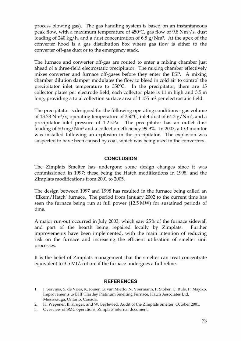
ELECTROSTATIC PRECIPITATOR The two major sources of off-gas are the 13.5 MVA furnace and the two 10’ x 15’ Peirce-Smith Converters. Off-gas from these two main sources is combined and sent through the Electrostatic Precipitator before eventually being vented to the atmosphere. The furnace operation is such that sealing of the furnace creates and maintains a negative pressure, at a gas temperature of approximately 425ºC and a maximum draft of 4 Nm3/s measured over 24 hours. Instantaneous peak flows are such that dust loading is approximately 3 468 kg/h at a dust concentration of 241 g/Nm3. An emergency stack is installed which can be used to isolate the ducting system downstream. A pneumatically actuated damper is installed for this. At the front end of the furnace, two matte tapping hoods above each of the tapholes are provided to minimize sulphur dioxide emissions whilst tapping matte. The two ducts are routed to join up with the main furnace off-gas duct. Converter off-gases are collected in air-cooled hoods that cover the converter mouth when the converter is in the blowing position. Dilution air drawn in through the gap between the hood and the converter reduces the off-gas temperature to less than 500ºC (representing a dilution in excess of 200% of
73
process blowing gas). The gas handling system is based on an instantaneous peak flow, with a maximum temperature of 450ºC, gas flow of 9.8 Nm3/s, dust loading of 240 kg/h, and a dust concentration of 6.8 g/Nm3. At the apex of the converter hood is a gas distribution box where gas flow is either to the converter off-gas duct or to the emergency stack. The furnace and converter off-gas are routed to enter a mixing chamber just ahead of a three-field electrostatic precipitator. The mixing chamber effectively mixes converter and furnace off-gases before they enter the ESP. A mixing chamber dilution damper modulates the flow to bleed in cold air to control the precipitator inlet temperature to 350ºC. In the precipitator, there are 15 collector plates per electrode field; each collector plate is 11 m high and 3.5 m long, providing a total collection surface area of 1 155 m2 per electrostatic field. The precipitator is designed for the following operating conditions - gas volume of 13.78 Nm3/s, operating temperature of 350ºC, inlet dust of 64.3 g/Nm3, and a precipitator inlet pressure of 1.2 kPa. The precipitator has an outlet dust loading of 50 mg/Nm3 and a collection efficiency 99.9%. In 2003, a CO monitor was installed following an explosion in the precipitator. The explosion was suspected to have been caused by coal, which was being used in the converters.
CONCLUSION The Zimplats Smelter has undergone some design changes since it was commissioned in 1997: these being the Hatch modifications in 1998, and the Zimplats modifications from 2001 to 2005. The design between 1997 and 1998 has resulted in the furnace being called an ‘Elkem/Hatch’ furnace. The period from January 2002 to the current time has seen the furnace being run at full power (12.5 MW) for sustained periods of time. A major run-out occurred in July 2003, which saw 25% of the furnace sidewall and part of the hearth being repaired locally by Zimplats. Further improvements have been implemented, with the main intention of reducing risk on the furnace and increasing the efficient utilisation of smelter unit processes. It is the belief of Zimplats management that the smelter can treat concentrate equivalent to 3.5 Mt/a of ore if the furnace undergoes a full reline.
REFERENCES 1. J. Sarvinis, S. de Vries, K. Joiner, G. van Mierlo, N. Voermann, F. Stober, C. Rule, P. Majoko,
Improvements to BHP Hartley Platinum Smelting Furnace, Hatch Associates Ltd, Mississauga, Ontario, Canada.
2. H. Wepener, B. Kruger, and W. Beylevled, Audit of the Zimplats Smelter, October 2001. 3. Overview of SMC operations, Zimplats internal document.

74
4. Review of SMC, Concentrator and Smelter as a plant for treatment of approximately 2.2 million tonnes of ore per annum from the Ngezi Open Cast Mine, Bateman, October 1999.
5. R.T. Jones, An overview of Southern African PGM Smelting, Nickel and Cobalt 2005: Challenges in Extraction and Production, 44th Annual Conference of Metallurgists, Calgary, Alberta, Canada, 21-24 August 2005, pp.147-178. http://www.mintek.co.za/Pyromet/Files/2005JonesPGMsmelting.pdf
6. R.T. Jones, JOM World Nonferrous Smelter Survey, Part II: Platinum Group Metals, JOM, December 2004, pp.59-63. http://www.mintek.co.za/Pyromet/Files/2004JonesPGMSmeltingSurvey.pdf
7. Zimplats website. http://www.zimplats.com
8. http://www.platinum.matthey.com/uploaded_files/publications/spnazim.pdf 9. J.R. Boldt, The winning of nickel, Longmans, Canada, 1967.

75

76