Embed Size (px)
DESCRIPTION
Citation preview
An Overview of Digital Communication and Transmission Chapter 4
By
Donavon M. Norwood
CS286
Dr. Moh
07/21/2009
2
Introduction - 4.1
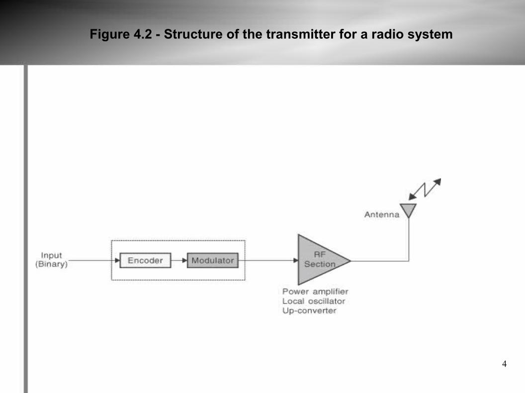
The equipment that is used to convert the information bearing signal into a suitable form for transmission over the communication channel and then back into a form that is comprehensible to the end user is called the transmitter and receiver. The transmitter of a radio system consists of: Source Encoder – converts the data stream into a form that is more resistant to
degradations in the communication channel. Modulator – takes a sine wave at a required frequency and modifies the signal
characteristics. RF Section – generates a signal of sufficient power at a required frequency. It
contains a power amplifier, a local oscillator and a up converter. Antenna – converts the electrical signal into a wave propagating in free space.
We can look at the encoder and modulator as one subsystem that maps data presented to it by the user interface onto the RF carrier for processing, amplification, and transmission by the RF section. The demodulator and decoder does the inverse by taking the received RF signal and inverse mapping the signal back to the data stream for transmission.
3
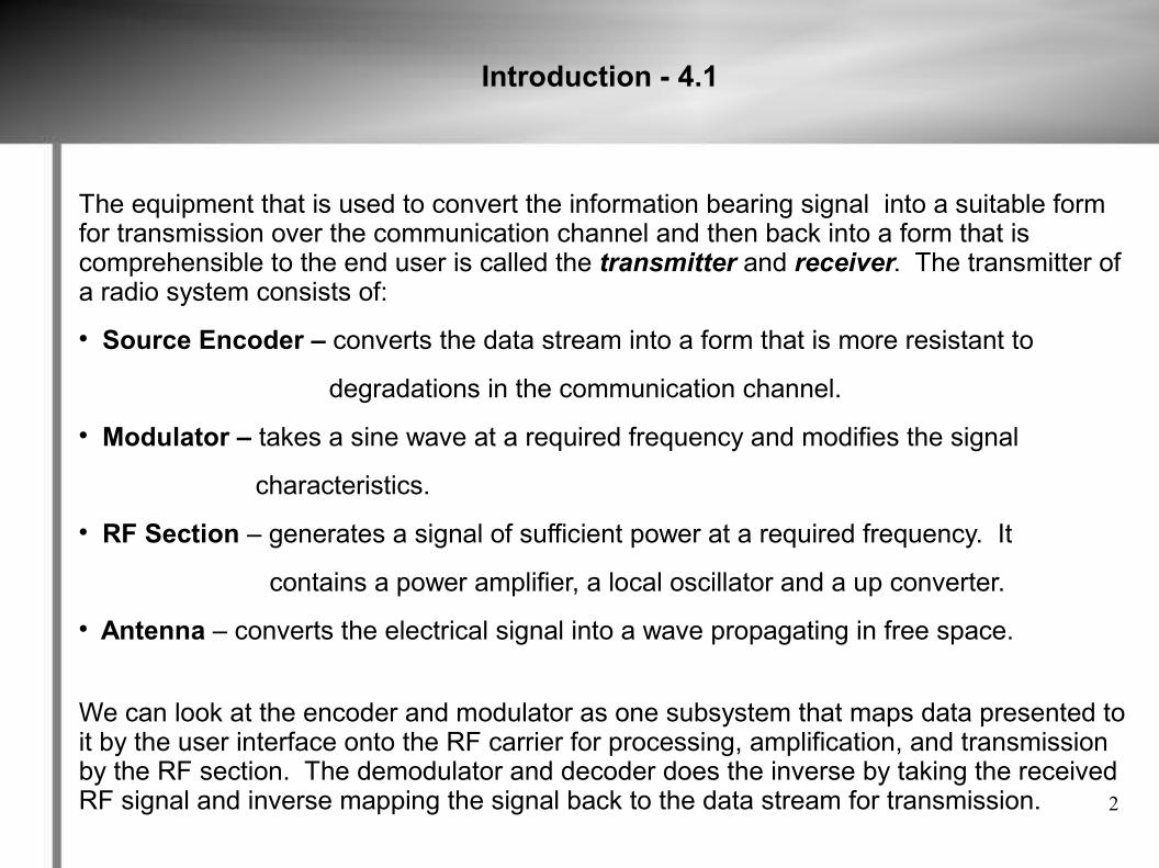
Figure 4.1 - Overview of a communication system
4
Figure 4.2 - Structure of the transmitter for a radio system
5
Baseband Systems - 4.2
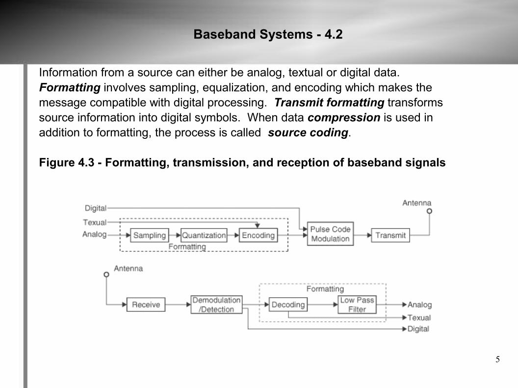
Information from a source can either be analog, textual or digital data. Formatting involves sampling, equalization, and encoding which makes themessage compatible with digital processing. Transmit formatting transformssource information into digital symbols. When data compression is used inaddition to formatting, the process is called source coding.
Figure 4.3 - Formatting, transmission, and reception of baseband signals
6
Messages, Characters and Symbols - 4.3
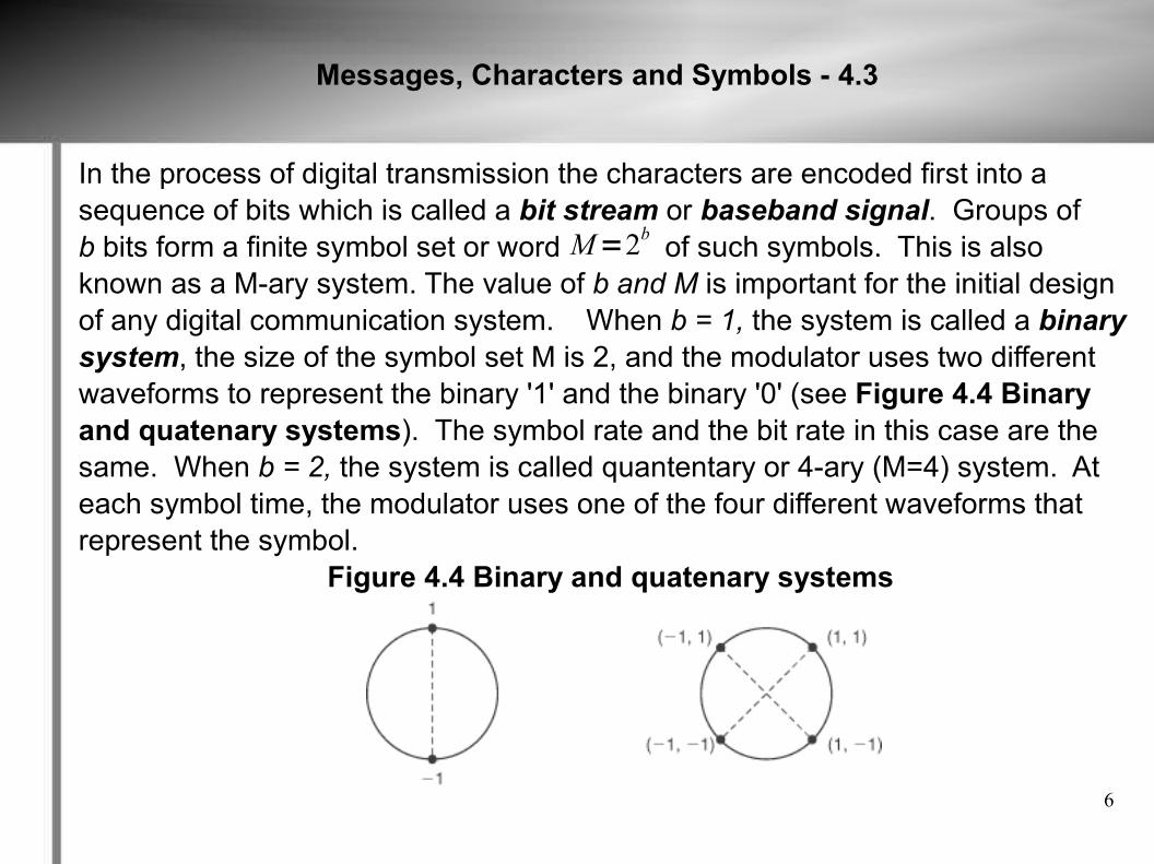
In the process of digital transmission the characters are encoded first into asequence of bits which is called a bit stream or baseband signal. Groups ofb bits form a finite symbol set or word of such symbols. This is alsoknown as a M-ary system. The value of b and M is important for the initial designof any digital communication system. When b = 1, the system is called a binarysystem, the size of the symbol set M is 2, and the modulator uses two differentwaveforms to represent the binary '1' and the binary '0' (see Figure 4.4 Binaryand quatenary systems). The symbol rate and the bit rate in this case are thesame. When b = 2, the system is called quantentary or 4-ary (M=4) system. Ateach symbol time, the modulator uses one of the four different waveforms thatrepresent the symbol.
Figure 4.4 Binary and quatenary systems
M=2b
7
Sampling Process - 4.4
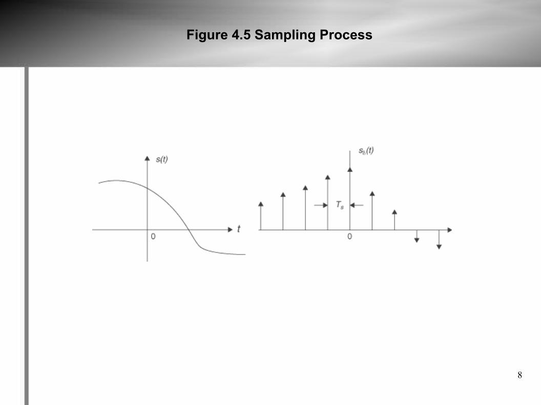
The first process in digital transmission is sampling, which converts the analog information into a digital format which is called a discrete pulse-amplitude-modulated waveform. The sampling process is usually described in time domain, which is the operation that is basic to digital signal processing and digital communication. The sampling process can be implemented in several ways with the most popular being the sample-and-hold operation. In this operation a switch and storage mechanism form a sequence of samples of the continuous input waveform, and the output of this is called pulse amplitude modulation (PAM), because the the successive output intervals are described as a successive sequence of pulses with amplitudes derived from the input waveform samples. The wave of a PAM waveform can be retrieved from a low pass filter if the sampling rate is chosen properly. The ideal form of sampling is called instantaneous sampling.
8
Figure 4.5 Sampling Process
9
Aliasing - 4.4.1
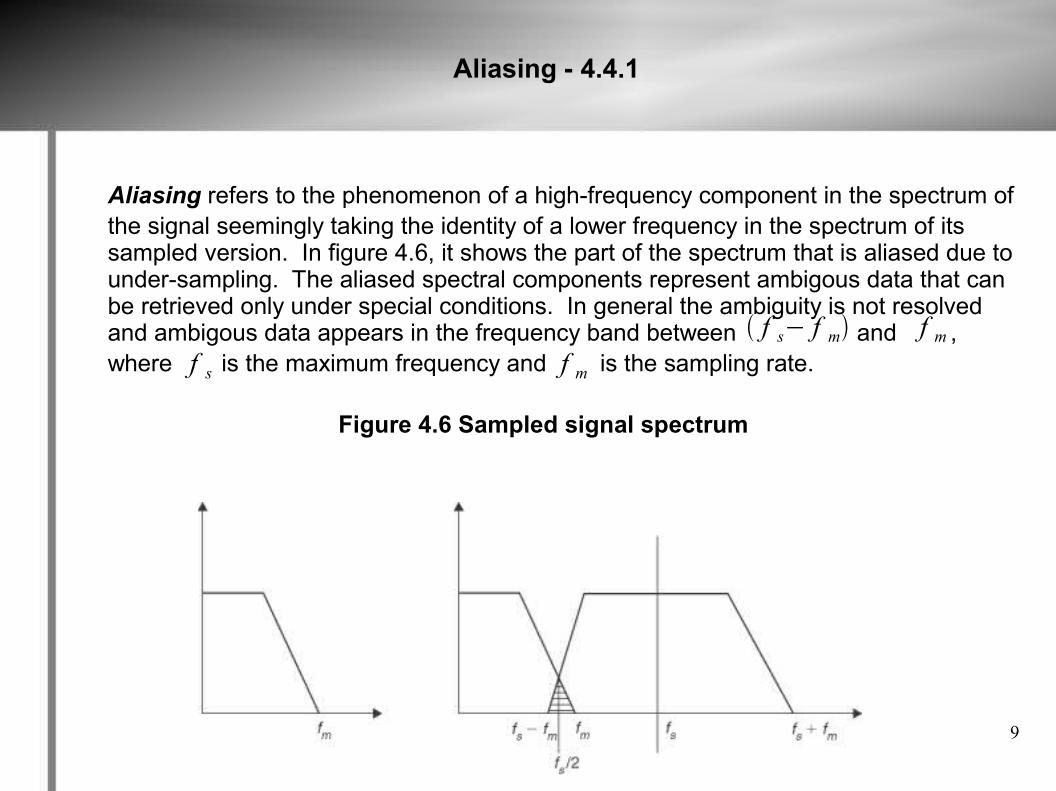
Aliasing refers to the phenomenon of a high-frequency component in the spectrum ofthe signal seemingly taking the identity of a lower frequency in the spectrum of its sampled version. In figure 4.6, it shows the part of the spectrum that is aliased due to under-sampling. The aliased spectral components represent ambigous data that can be retrieved only under special conditions. In general the ambiguity is not resolved and ambigous data appears in the frequency band between and , where is the maximum frequency and is the sampling rate.
Figure 4.6 Sampled signal spectrum
f s− f m f mf mf s
10
Aliasing – 4.4.1 (Continued)
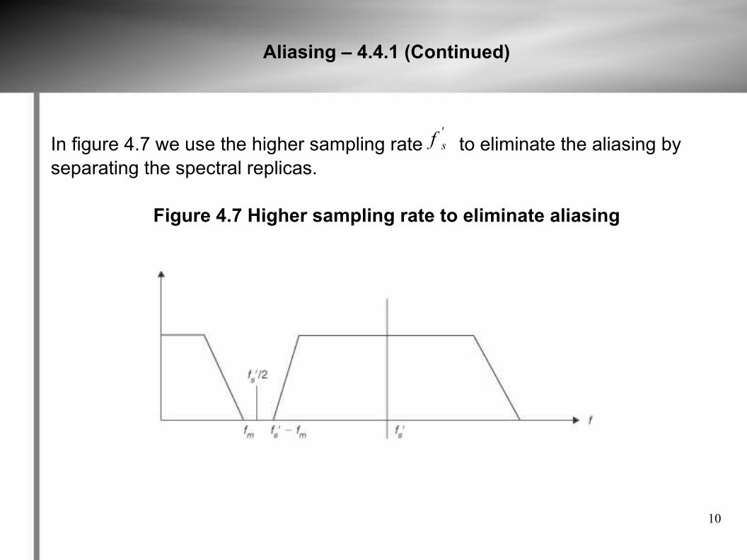
In figure 4.7 we use the higher sampling rate to eliminate the aliasing byseparating the spectral replicas.
Figure 4.7 Higher sampling rate to eliminate aliasing
f s'
11
Aliasing – 4.4.1 (Continued)
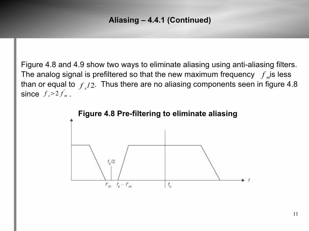
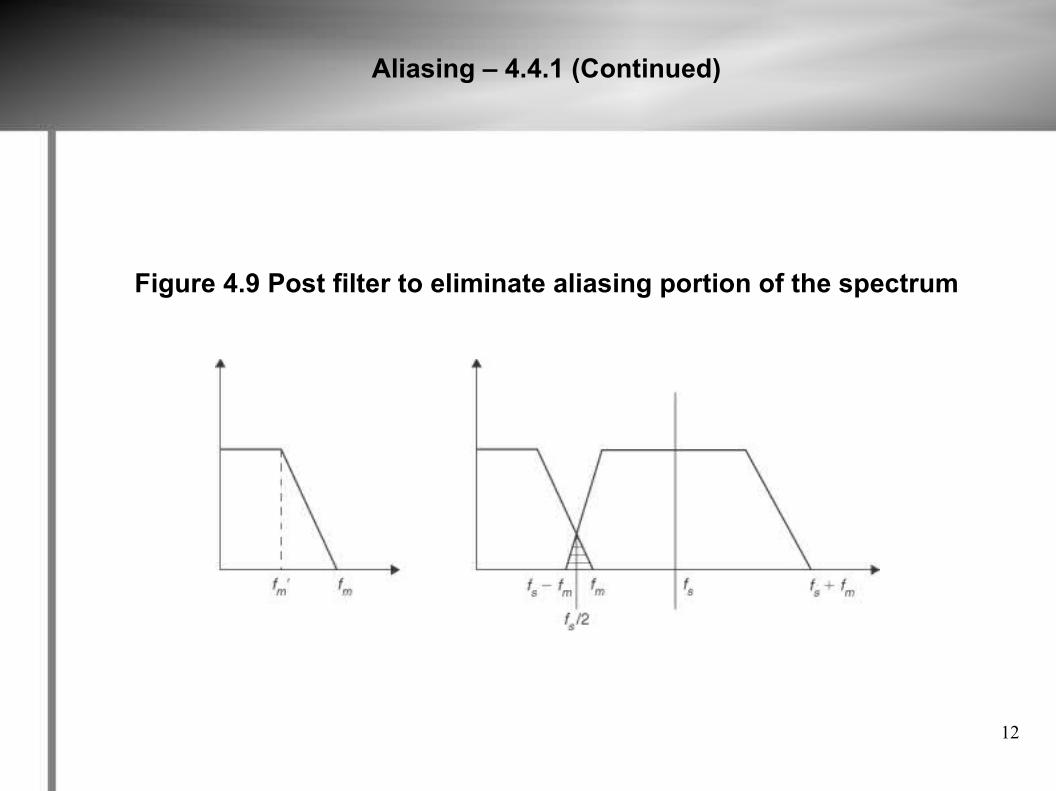
Figure 4.8 and 4.9 show two ways to eliminate aliasing using anti-aliasing filters.The analog signal is prefiltered so that the new maximum frequency is lessthan or equal to . Thus there are no aliasing components seen in figure 4.8since .
Figure 4.8 Pre-filtering to eliminate aliasing
f s /2f s2 f m
'
f m
12
Aliasing – 4.4.1 (Continued)
Figure 4.9 Post filter to eliminate aliasing portion of the spectrum
13
Quantization - 4.4.2
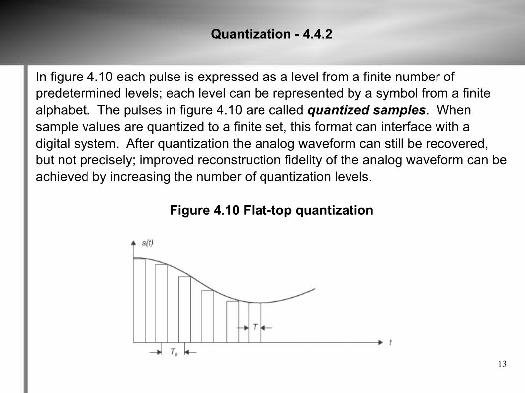
In figure 4.10 each pulse is expressed as a level from a finite number ofpredetermined levels; each level can be represented by a symbol from a finitealphabet. The pulses in figure 4.10 are called quantized samples. Whensample values are quantized to a finite set, this format can interface with adigital system. After quantization the analog waveform can still be recovered,but not precisely; improved reconstruction fidelity of the analog waveform can beachieved by increasing the number of quantization levels.
Figure 4.10 Flat-top quantization
14
Uniform Quantization – 4.4.4
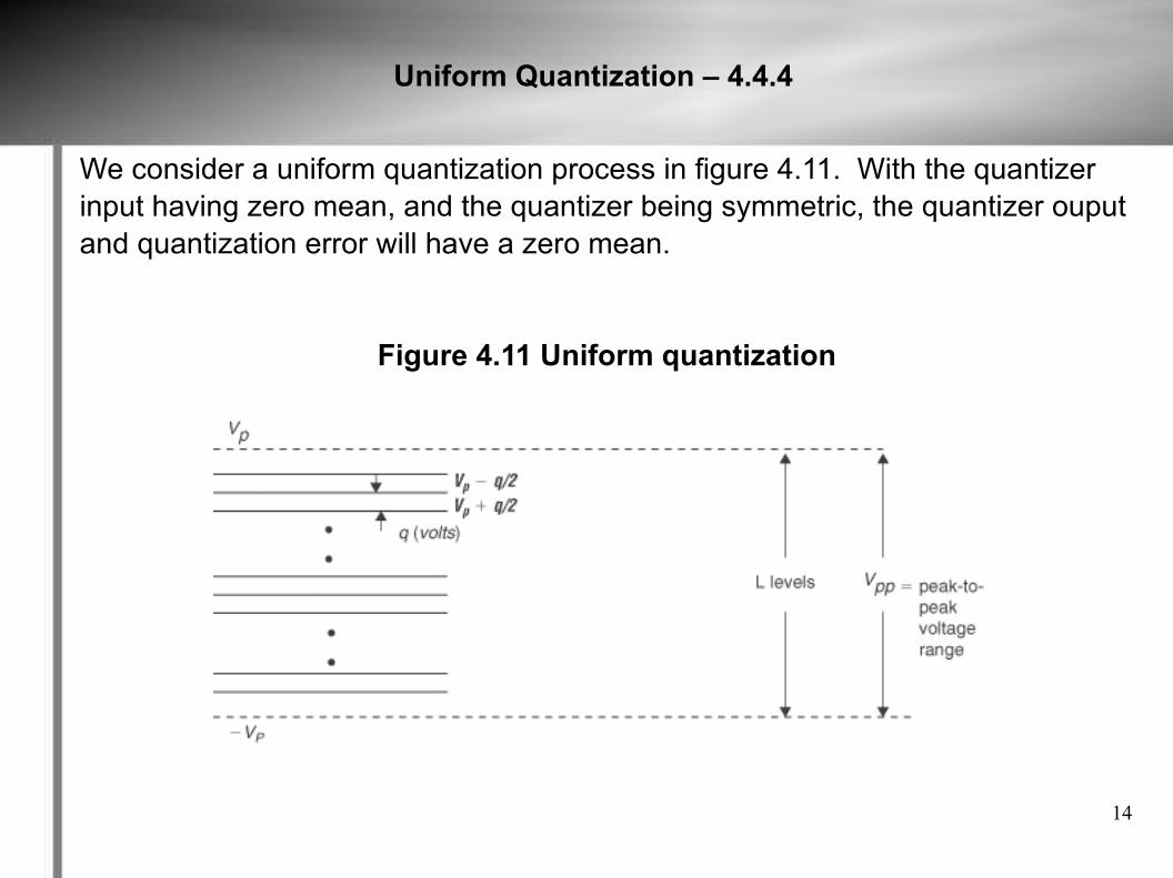
We consider a uniform quantization process in figure 4.11. With the quantizerinput having zero mean, and the quantizer being symmetric, the quantizer ouputand quantization error will have a zero mean.
Figure 4.11 Uniform quantization
15
Voice Communication - 4.5
Voice communication has very low speech volumes that predominate: 50% ofthe time, the voltage characterizing detected speech energy is less than ¼ ofthe rms value of the voltage. Large amplitude are rare, in which only 15% of thetime does the voltage exceed the rms value. Uniform quantization would bewasteful for speech signals. In a system that uses equally spaced quantizationlevels, the quantization noise is the same for all signal magnitudes because thenoise depends on the step size of quantization. Nonuniform quantization canprovide better quantization of the weak signals versus uniform quantization, andalso coarse quantization of the strong signal. The nonuniform quantization isused to make SNR a constant for all signals within the input range Nonuniformquantization is achieved by first disorting the original signal with a logarithmiccompression, and then using a uniform quantizer. A device called a expanderat the receiver to for compression. The whole process of compression is calledcompanding. There are two compression algorithms used today: and A-law.
−law
16
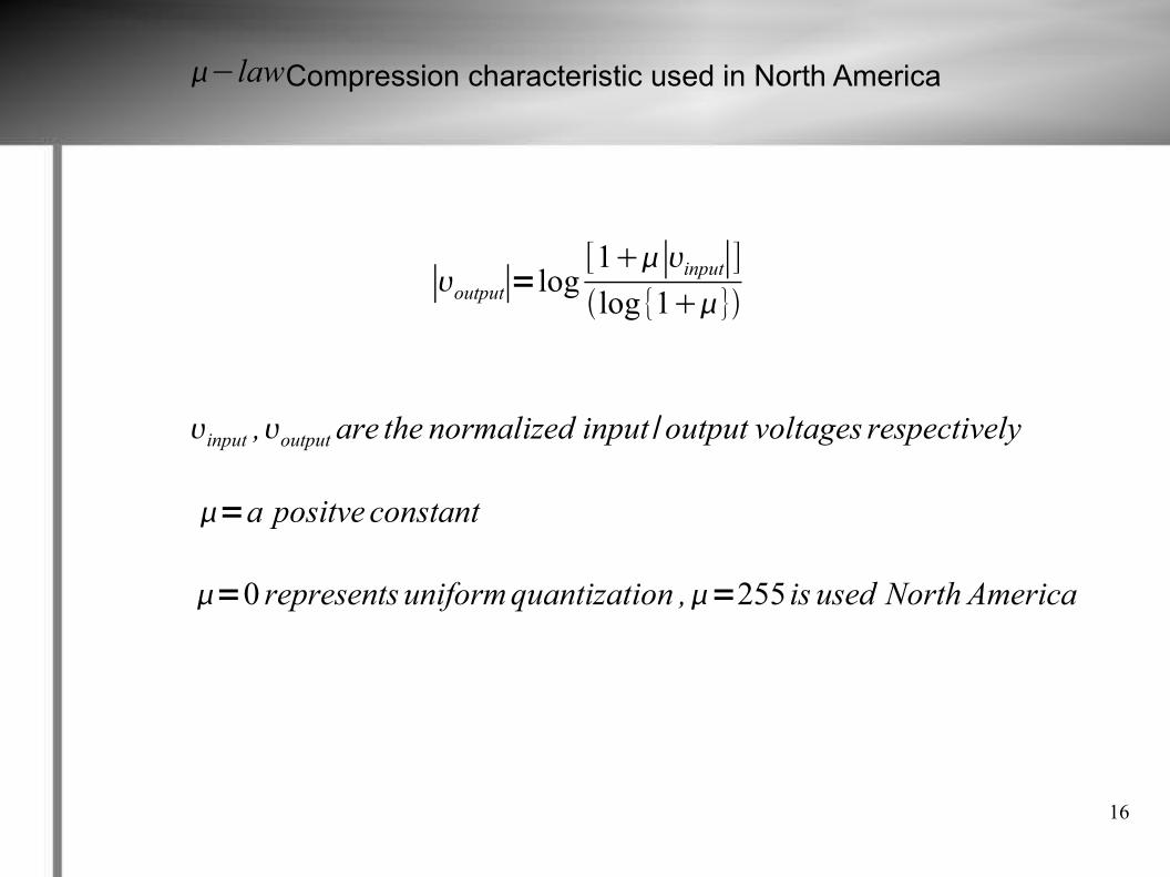
Compression characteristic used in North America
−law
∣output∣=log[1∣input∣]log{1}
input ,output are the normalized input /output voltages respectively
=a positve constant
=0 represents uniformquantization ,=255 is used North America
17
Pulse Amplitude Modulation (PAM) - 4.6
Pulse Amplitude Modulation (PAM) is a process that represents a continuousanalog signal with a series of discrete analog pulses in which amplitude of theinformation signal at a given time is encoded as a binary number. Pulse Amplitude Modulation (PAM) is now rarely used and has been replaced byPulse Code Modulation (PCM). Two operations involved in the PulseAmplitude Modulation (PAM) signal are:
1. Sampling of the message s(t) every seconds, where is selected according to the sampling theorem.
2. Lengthening the duration of each sample obtained to some constant T.
These operations are referred together as sample and hold. The reason forincreasing the duration of each sample is to avoid the use of excessivebandwidth, since bandwith is proportional to pulse duration.
T s f s=1/T s
18
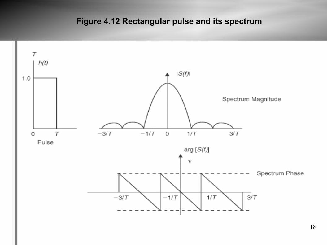
Figure 4.12 Rectangular pulse and its spectrum
19
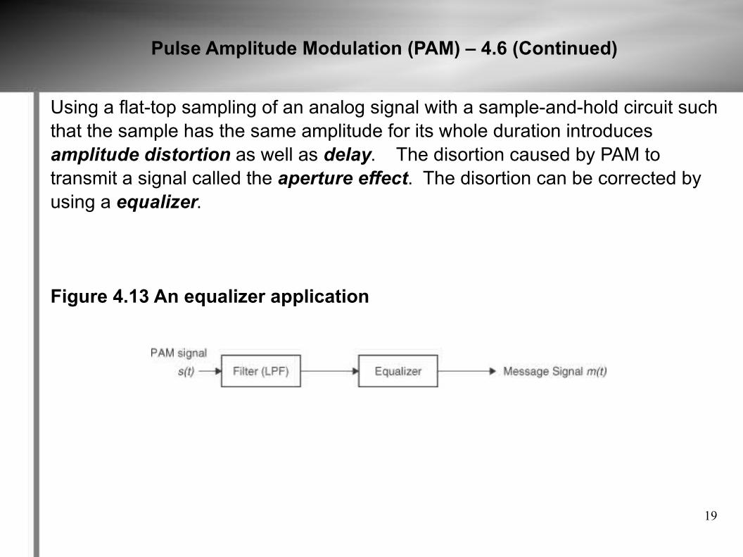
Pulse Amplitude Modulation (PAM) – 4.6 (Continued)
Using a flat-top sampling of an analog signal with a sample-and-hold circuit suchthat the sample has the same amplitude for its whole duration introducesamplitude distortion as well as delay. The disortion caused by PAM totransmit a signal called the aperture effect. The disortion can be corrected byusing a equalizer.
Figure 4.13 An equalizer application
20
Pulse Code Modulation (PCM) - 4.7
Pulse Code Modulation (PCM) is a digital scheme for transmitting analog data.It converts an analog signal into digital form. Using PCM it is possible to digitizeall forms of analog data, including full motion video, voice, music, telemetry, etc. To obtain a PCM signal from an analog signal at the source (transmitter) of acommunication circuit, the analog signal is sampled at regular time intervals.The sample rate is several times the maximum frequency of the analog signal.The amplitude of the analog signal is rounded off to the nearest of severalspecific, predetermined levels (quantization). The number of levels is always apower of 2. The output of PCM is a series of binary numbers, each representedby some power of 2 bits. At the destination of the communication circuit, thePCM converts the binary numbers back into pulses having the same quantumlevels as those in the modulator. These pulses are then further processed torestore the original analog waveform. When PCM is applied to a binary symbol,the resulting binary wave form what is known as pulse code modulationwaveform. When PCM is applied to a non binary number, the resulting wave iscalled M-ary pulse modulation waveform.
21
Modulation - 4.9
Baseband signals are generated at low rates, therefore these signals are modulated onto a radio frequency carrier for transmission. Baseband signal s(t) is complex and can be represented mathematically as , where a(t) is the sampling rate and is the phase. The modulation can be classified as linear modulation or nonlinear modulation. A modulation process is linear when and are linearly related to the message information signal. Examples of linear modulation are amplitude modulation in which the modulating signal signal affects only the amplitude of the modulated signal, and phase modulation is where the modulated signal affects only the phase of the modulated signal.
st =a t e jt t
a t cost a t sint
22
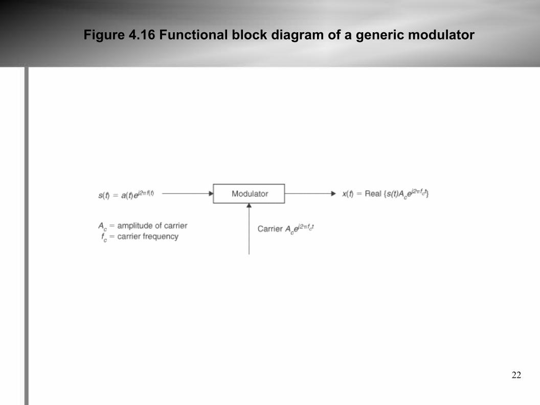
Figure 4.16 Functional block diagram of a generic modulator
23
Thank You
References:
Wireless Communication and Networking, Vijay K. Garg