Embed Size (px)
Citation preview

An Overview of Carbon Capture Technological Processes from Fossil Fuels Utilization - A
Portuguese Strategic Perspective
Clemente Pedro Nunes1, Filomena Pinto2, Carla Pinheiro1
1 IST, Campus Alameda, Av. Rovisco Pais, 1, 1049-001 Lisboa, Portugal2 LNEG, Estrada do Paço do Lumiar, Nº 22, 1649-038 Lisboa, Portugal
10th – 11th March, 2015
CCS in Process Industries - State-of- the-Art and Future Opportunities1

Objectives Introduction Overview of CCS technologies and R&D Needs
CO2 capture Post-combustion capture Pre-combustion/syngas approach Oxy-combustion option Co-combustion and Co-gasification
CO2 Transportation CO2 Storage and Novel Utilisations
Economic analysis of CCS Main Conclusions - The Future CCS and the Portuguese Industry
Table of Contents
2

GNIP Group is a Portuguese Group that promotes energy efficiency in our country, in order to increase its economic competitiveness.
GNIP includes Universities, Major Industries and National Laboratories and as such is responsible for the Portuguese participation in IETS.
It must be stressed that Portugal has one of the highest shares in the EU in what concerns the use of renewable sources in the overall energy mix, which currently is already around 25%.
For GNIP it is essential to evaluate the current status of Carbon Capture and Storage (CCS) technologies in order to better understand the economic consequences of the present and future policies to the Portuguese industry within the framework to be derived at a National and European levels.
Objectives
3

Introduction
Portugal has to work within the EU framework, but its economy has to compete with countries that do not obey to the Kyoto Protocol.
As such we have to analyse very carefully the economics of the technologies that reduce the carbon intensivity, in which CCS is included.
But we should not forget other perspectives including Carbon Capture and Utilisation (CCU), and also the fact that Europe and Portugal have consistently reduced its share of the worldwide GHG emissions.
4

Introduction - CO2 Emissions Statistics
Change in CO2 emissions by region (2010-11):
Source: IEA, CO2 EMISSIONS FROM FUEL COMBUSTION Highlights, 2013.
Fuel shares in global CO2 emissions:
Trend in CO2 emissions from fossil fuel combustion:
5
CO2 capture Pre-combustion Capture or Gasification Oxy-combustion Post-combustion Capture Co-combustion and Co-gasification
CO2 Transport CO2 Storage
Overview of CCS Technologies
CO2 Novel Utilisations Microalgae (artificial photosynthesis) Conversion to Fuels (CH3OH, CH4, etc.) Conversion to polymers Pharmaceuticals, building materials, etc.
CCS
CCU
6
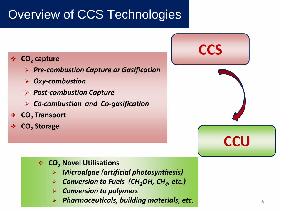
Overview of CCS Technologies
CO2 Capture Pre-combustion
Capture (Gasification)
Oxy-combustion
Post-combustion Capture
Co-combustion and Co-gasification
Fuel (Coal or Gas)
Air
Gasification
Syngas Cleaning
Gas Conditioning
CO2 CaptureProduction of Heat or Power
AirO2
Coal
Gas
N2
Air Separation Unit
CO2Compressionand Storrage
O2CO2
CO2
Combustion(Production of Heat or Power)
CO2 Capture
Air
CO2Fuel
(Coal or Gas)
N2, O2
N2CO2
CO2Purification
Oxy-Combustion
Post-Combustion
Pre-Combustion
Air Separation Unit
Reforming
Combustion(Production of Heat or Power)
7

CO2 Capture - Post-combustion Capture
Absorption: Chemical (Amines)Physical (Ionic Liquids)
Adsorption Chemical looping: metal oxides as CaO Cryogenic separationMembranes Biofixation by microalgae
Overview of CCS Technologies
Combustion(Production of Heat or Power)
CO2 Capture
AirFuel
(Coal or Gas)
N2, O2Post-Combustion
CO2
8

CO2 Capture - Post-combustion Capture
Absorption Benefit Technology available to be used in new or in existing power plants
Absorption Drawbacks High degradation rates, mostly due to the presence of contaminants
like SOx and NOx Corrosion in the presence of O2 Need for large scrubbers and great energy requirements for regeneration.
Overview of CCS Technologies
Chemical Absorption Amines – Diethanolamine (DEA), Monoethanolamine (MEA)
Methyldiethanolamine (MDEA) Physical Absorption
Solvents – Dimethylether of polyethylene glycol (Selexol process), cold methanol (Rectisol process), propylene carbonate (Fluor solvent process) and sulfolane. Hybrid solvents – Purison, Sulfinol (mixture of sulfolane and alkanolamines), MDEA (activated Methyldiethanolamine) and UCARSOL

CO2 Capture - Post-combustion Capture
Adsorption Drawbacks The energy needed for regeneration in TSA is high The energy needed to achieve high pressure in PSA is high Their capacity and CO2 selectivity is low Further R&D is needed to develop new adsorbents with higher
adsorption capacities and better selectivity
Overview of CCS Technologies
Adsorption CO2 is captured by high surface area materials:
activated carbons and zeolites. Different technologies: Pressure swing adsorption (PSA),
Temperature swing adsorption (TSA)Electrical swing adsorption (ESA)
PSA and TSA processes are available at commercial scale
10
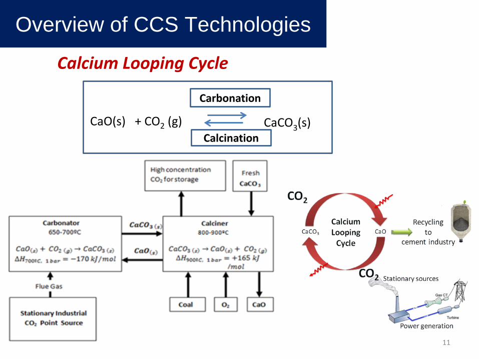
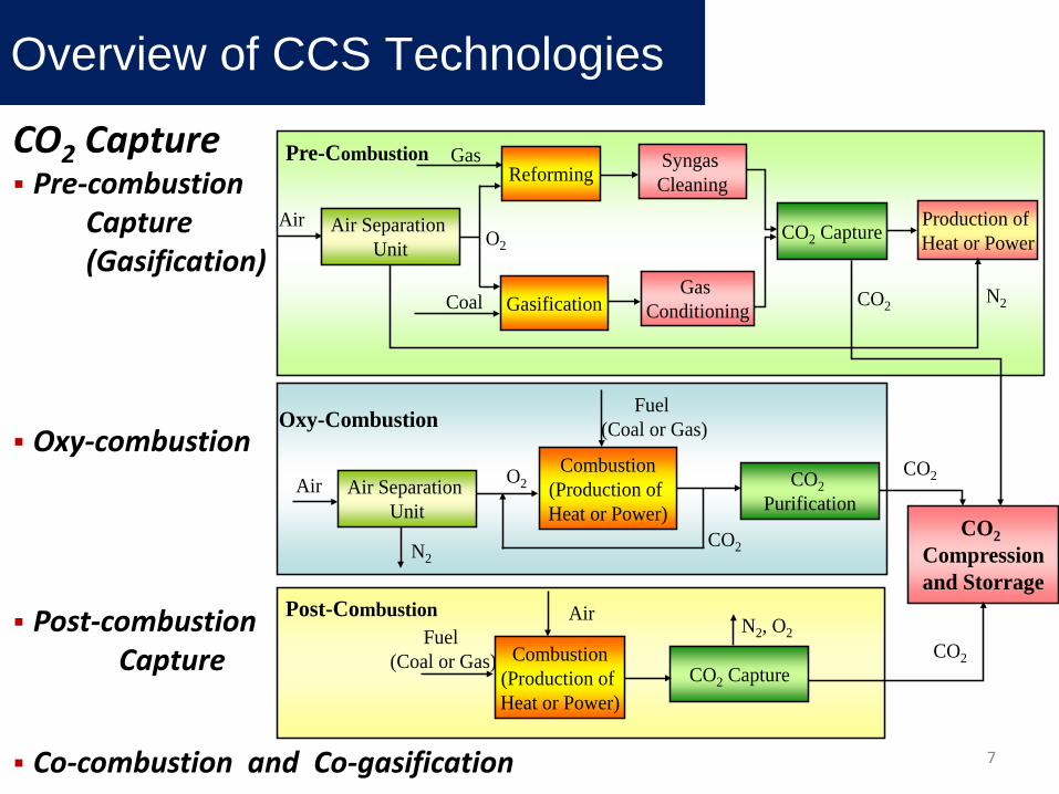
Calcium Looping Cycle
CaO(s) + CO2 (g) CaCO3(s)
Overview of CCS Technologies
Carbonation
Calcination
11

CO2 Capture - Post-combustion Capture
Overview of CCS Technologies
Calcium Looping Cycle Initial high uptake of CO2 Low energy penalty and operating costs Use of cheap and nontoxic sorbents Purge of CaO: synergies with cement industry Pre-treatment of flue gas is not needed High adsorption capacity for CO2 at high temperature Production of a pure CO2 stream for sequestration.
Calcium Looping Cycle Drawbacks Sintering of CaO sorbent may occur during high-temperature
calcination, causing the sorbent deactivation due to grain growth and pore shrinkage.
Decrease of CO2 capture capacity and stability of the sorbent with increasing number of carbonation/calcination cycles. 12

CO2 Capture - Post-combustion Capture
Cryogenic Separation Drawbacks This process is highly energy dependent and should only be applied to
flue gases with high CO2 concentrations R&D needs are related with the development of more efficient
refrigeration processes to allow cryogenic separation to be less energy intensive and more cost competitive
Cryogenic Separation Flue gas is cooled below CO2 boiling point, to condense CO2 and separate it from other gases Particulates and other gaseous components may be also removed from flue gas Separation into pure components depends on flue gas composition, as it affects boiling points Liquid CO2 may be easily transported without compression requirements
Overview of CCS Technologies
13

CO2 Capture - Post-combustion Capture
Membrane Separation Drawbacks A high degree of separation can only be achieved with multiple
membrane stages and/or by recycling some streams Several membranes with different characteristics are needed to
obtain CO2 with high purity, due to flue gas several components
Membrane Separation Either gas separation membranes or gas absorption membranes may be used In gas absorption membranes, CO2 diffuses through the membrane and is removed from the gas stream In gas separation membranes, the separation depends on the solubility or diffusivity of the gas molecules in the membrane and on differences in partial pressure from one side of the membrane to the other
Overview of CCS Technologies
14

CO2 Capture - Oxy-combustion
O2 is used instead of air to avoid N2 dilution of flue gases Flue gases (mainly CO2) are recirculated to help temperature control during combustion As O2 is used near stoichiometric conditions (95 a 99%), flue gases main compounds are CO2 (> 90 a 95% dry basis), steam and minor amounts of SOx e NOx After steam condensation and NOx, SOx and O2 removal, a CO2stream is obtained for storage
Overview of CCS Technologies
Fuel (Coal or Gas)
Air Air Separation Unit
O2
N2CO2
CO2Purification
Oxy-Combustion
Combustion(Production of Heat or Power)
CO2
15

CO2 Capture - Oxy-combustion
Benefits: Production of flue gas without N2 Avoids the costly post-combustion CO2 capture processes
Drawbacks: Requires an expensive air separation unit (ASU) for oxygen purification Lower efficiency due to the cost of ASU Requires a large portion (roughly 70%) of flue gas stream to be recycled back to the boiler to maintain normal operating temperatures Requires careful sealing to prevent any leakage of air into the flue gas
Overview of CCS Technologies
16

CO2 Capture - Pre-combustion Capture (Gasification)
Carbon is removed from the fuel before combustion Gasification to produce syngas, whose main components are: CO, CO2 , H2 and CH4 Syngas cleaning to remove particulates: tar, NH3, H2S and HClWater gas-shift reaction: CO + H2O ⇆ CO2 + H2 (41kJ/mol) CO2/H2 separation. A CO2 stream ready for storage H2 rich fuel for energy production is obtained
Overview of CCS Technologies
Gasification
Syngas Cleaning
Gas Conditioning
CO2 CaptureAirO2
Coal
Gas
CO2
Pre-Combustion
Air Separation Unit
Reforming
17

Overview of CCS Technologies
Gasification
PartículatesRemoval S, Cl, etc.
Compounds Abatement
Tar and N CompoundsAbatement
C-based Compounds Abatement
Water gas Shift
Reaction H2
Separation
CO2
Hot Syngas Cleaning
Steam
Steam Syngas(rich in H2)
Coal
Steam Char
Ar / O2
Syngas Upgrading
CO2 Capture - Pre-combustion Capture (Gasification)
18
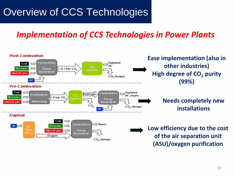
Implementation of CCS Technologies in Power Plants
Needs completely new installations
Low efficiency due to the cost of the air separation unit (ASU)/oxygen purification
Ease implementation (also in other industries)
High degree of CO2 purity (99%)
Overview of CCS Technologies
19

Different fuels and biomass wastes are mixed
before combustion or gasification
CO2 reduction emissions are achieved by:
Substituting fossil fuels by biomass/wastes
Interaction between different fuelsand compositions (coal, biomass and wastes)
However, the use of wastes with undesirable elements, such as:
halogens, sulphur and heavy metals may lead to the formation of
pollutants precursors and thus may oblige to more expensive gas
cleaning processes
Co-gasification and Co-combustion
Overview of CCS Technologies
20

CO2 Transport and Storage
CO2 Storage Depleted oil and gas reservoirs Use of CO2 in enhanced oil recovery Deep unused saline water-saturated reservoir rocks Deep unmineable coal seams Use of CO2 in enhanced coal bed methane recovery Other options (basalts, oil shales, cavities)
Overview of CCS Technologies
CO2 Transport Before transport CO2 is compressed to near supercritical conditions Water and other contaminants need to be removed. Transport by pipeline or by ships (large distances)
21
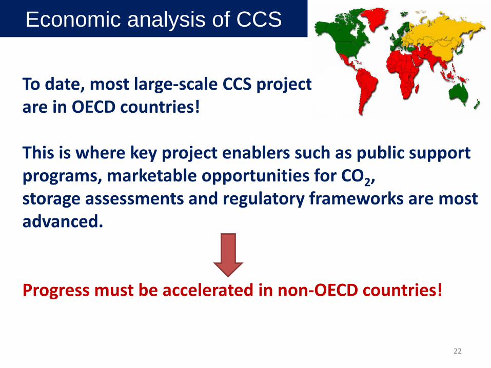
To date, most large-scale CCS projects are in OECD countries!
This is where key project enablers such as public support programs, marketable opportunities for CO2,storage assessments and regulatory frameworks are most advanced.
Progress must be accelerated in non-OECD countries!
Economic analysis of CCS
22

Overall Cost of CCS includes: Cost of capture Cost of compression Cost of transport Cost of storage
The cost of capture means the cost of the technological processes by which CO2 is separated from the other gas components present in the flue gas from the burning of fossil fuels.
There have been a limited number of studies of CO2 capture costs for industrial processes other than power plants and cement plants...
Economic analysis of CCS
23

More relevant than the capture cost is the CO2 avoidance cost: the cost after installation of the capture equipment including the energy penalty with the initial costs.
The CO2 capture step (which includes CO2 compression) accounts for 80% to 90% of this cost increase.
Given the limited experience with capture from power plants at a large scale, there will probably be a period of learning, during which costs will likely decline.
Economic analysis of CCS
Cost of CO2 capture is the largest component of the CCS value chain
24

Levelized cost of electricity (LCOE) for new-build power plants with or without CCS
Power plants:IGCC - Integrated Gas Combined Cycle PCoal - Pulverized Coal NGCC - Natural Gas Combined Cycle
Power Plant Type (new-build)
Average LCOE without CCS ($/MWh)
Average LCOE with CCS ($/MWh)
IGCC 97.8 141.7
PCoal 75.0 137.1
NGCC 74.7 108.9
Economic analysis of CCS
25

Current power plant efficiencies and Capture System Energy PenaltyPost-combustion capture on PCoal plants is the most energy-intensive!
Power plant type, and capture system type
Net plant efficiency
(%) without CCS
Net plant efficiency
(%) with CCS
Energy penalty: Added fuel input (%) per net kWh output
Existing subcritical PCoal,post-combustion capture 33 23 40
New supercritical PCoal,post-combustion capture 40 31 30
New supercritical PCoal,oxy-combustion capture 40 32 25
New IGCC,pre-combustion capture 40 34 19
New natural gas combinedcycle, post-combustion capture 50 43 16
Source: Carbon Capture: A Technology Assessment, Peter Folger, 2013.Notes: All efficiency values are based on the higher heating value (HHV) of fuel. For each plant type, there is a range of efficiencies around the representative values shown here.
Economic analysis of CCS
26

List of penalties for existing coal combustion plants:
Lower plant efficiency
More fuel needed to generate electricity relative to a similar plant without CO2 capture
More solid waste produced
More chemicals, such as ammonia and limestone, needed (per unit of electrical output) to control NOx and SO2 emissions
Additional cooling water needed (for current amine capture systems)
Economic analysis of CCS
27
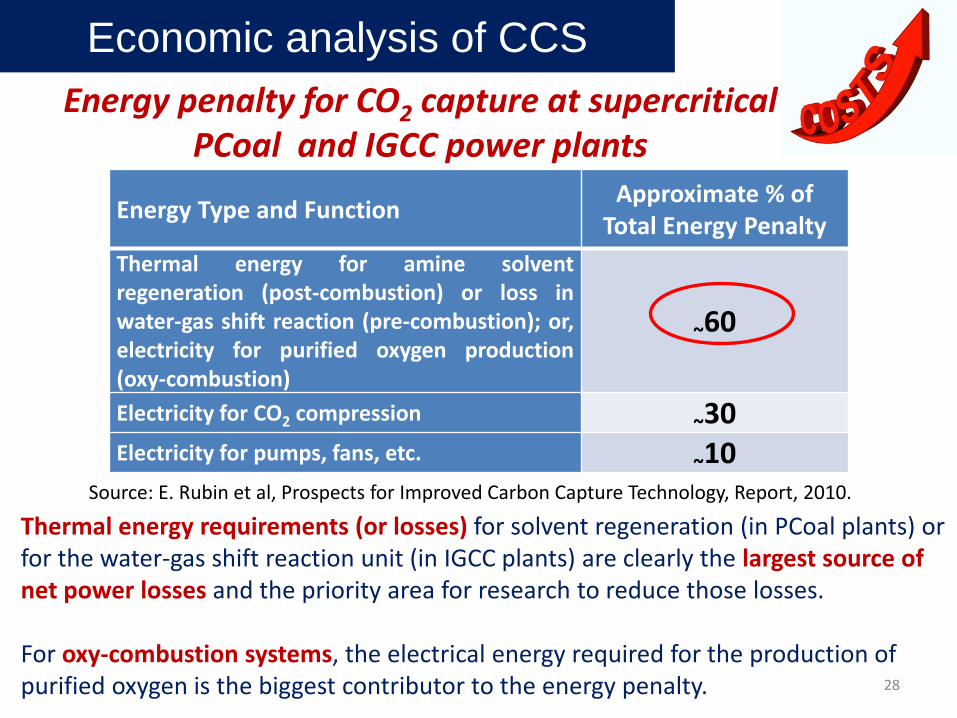
Energy Type and Function Approximate % of Total Energy Penalty
Thermal energy for amine solventregeneration (post-combustion) or loss inwater-gas shift reaction (pre-combustion); or,electricity for purified oxygen production(oxy-combustion)
~60
Electricity for CO2 compression ~30Electricity for pumps, fans, etc. ~10
Energy penalty for CO2 capture at supercritical PCoal and IGCC power plants
Source: E. Rubin et al, Prospects for Improved Carbon Capture Technology, Report, 2010.
Thermal energy requirements (or losses) for solvent regeneration (in PCoal plants) or for the water-gas shift reaction unit (in IGCC plants) are clearly the largest source of net power losses and the priority area for research to reduce those losses.
For oxy-combustion systems, the electrical energy required for the production of purified oxygen is the biggest contributor to the energy penalty.
Economic analysis of CCS
28

Industrial CO2 Source Cost of CO2 Capture and Transport($/Metric ton CO2)
Coal and biomass-to-liquids 36.10
Natural gas processing 36.29Hydrogen plants 36.67 to 46.12Refineries (Hydrogen) 36.67 to 46.12Ammonia plants 39.69Ethanol plants 42.15Cement plants 81.08
Estimated cost of CO2 capture and transportation for various industrial CO2 Sources
Source: U.S. Energy Information Administration Annual Energy Outlook (AEO), 2011.
Economic analysis of CCS
29

Economic analysis of CCS
Up to 2013, no large-scale CO2 capture projects have been implemented from cement plants.
Up to now, a limited number of studies have explicitly estimated the cost of CO2 avoidance for cement plants.
At the moment, the studies we have reviewed suggest thatOxyfuel is estimated to have a lower cost than post-combustioncapture, however this does not take into account the costs ofoxygen purification. Such views need to be tempered by thetechnical and economic improvements associated with post-combustion emerging technologies:
Calcium looping post-combustion capture technology is an emerging technology for the cement industry.
CO2 capture in the cement industry
30

Main CO2 capture performance indicators (modelling study) of a reference cement plant with and without CO2 capture
Economic analysis of CCS
TechnologyBase case:
No Capture
Post-combustion Amine
scrubbing
Post-combustionCa Looping
Oxy-combustion
Capture efficiency (%) - 85 85 63CO2 capture energypenalty (kJ/kg CO2) - 4952.2 2806.6 929.7*
CO2 in flue Gas (%) 34.1 7.3 11.4 14.7* This value does not include the energy consumption costs for oxygen purification.Source: K. Vatopoulos, E. Tzimas, Journal of Cleaner Production, 32 (2012) 251-261.
• Advantage of the Calcium Looping (Ca Looping) process over Amine scrubbing, in terms of energy penalty for CO2 capture.
• Less capture efficiency for Oxy-combustion technology, less energy penalty (if not taking into account the energy consumption costs for oxygen purification) and higher concentration of CO2 in the flue gases. 31

Economic analysis of CCSCement plant performance assumptions and normalised costs of
CO2 avoidance (US$/tCO2)
* Adjusted to common location (Europe), fuel cost (€2.5/GJ for coal) and discount rate (10%).Source: Li et al., Energy Policy, 61 (2013) 1377–1387. PC-MEA – Post-combustion Mono Ethanol Amine
StudyIEA GHG (2008)
Mott MacDonald
IEA GHG (2008) Mott
MacDonald
Australian Industrial CO2 capture
Ho et al. (2011)
Guangdong Cement Plant CCS study
Liang and Li (2012)
Plant Location North East Scotland, UK
North East Scotland, UK Australia Guangdong, China
Capture Technology PC-MEA Oxyfuel PC-MEA PC-MEA (retrofit)
CO2 Avoided (kt/y) 594 39.7 750 1294
CO2 Captured (kt/y) 1068 465 770 2151
Cost of CO2 emissionsavoided (US$/tCO2)adjusted*
139.7 51.6 Insufficientinformation 83.8
For cement plants, Oxyfuel is estimated to have a lower CO2 avoided costcompared to post-combustion capture , but… it has a lower capture efficiency and requires high energy consumption costs in oxygen purification!!
32

The Future
33

Main actions for the period from now to 2020 include: Introduction of financial support mechanisms for research, development and demonstration, and facilitation of multi-lateral
financing, Complete the legal and regulatory frameworks at the international,
national and provincial levels, Increase efforts towards public and stakeholders awareness, Support the introduction of CCS in non-OECD countries through
technology exchange and financial support, CO2-EOR implementation outside of North America, Generalise the capture-ready concept for new plants, Continue the knowledge capture from existing projects, Increase the investments in technologies to decrease the capture cost. (International Energy Agency (IEA), Technology Roadmap: CO2 Capture and Storage, OECD/IEA, Paris, 2013)
Main Conclusions - The Future

In the subsequent decade (from 2020 to 2030) key actions are the following:
• Manage the transition from demonstration to large-scale deployment,
• Support the development of the required infrastructure, e.g. main CO2 transport pipelines,
• Standardise practices for storage, including monitoring and verification,
• Continue the development and deployment of capture technologies and minimise the electricity output penalty,
• Expand CCS use in the industry (steel, cement, refineries, pulp and paper),
• Increased participation of non-OECD countries in the large-scale deployment of CCS.
(International Energy Agency (IEA), Technology Roadmap: CO2 Capture and Storage, OECD/IEA, Paris, 2013)
Main Conclusions - The Future
35

CCS and the Portuguese Industry
As it was shown in slide 29 the cost of capture and transportation of CO2 is estimated between 36 and 81 US$/Metric ton CO2, and this does not yet include the storage costs that can also be considerable.
Of course, in the case of Portugal we can give as an alternative, a great contribution to CCU, by optimizing the use of our forests that cover more than 36% of our territory, to absorb in a sustainable way CO2 from the atmosphere.
As such, we consider that any political attempt to increase the value of the carbon taxes in order to force an uneconomical introduction of CCS technologies in industry, shall have to be made on a worldwide scale.
36

CCS and the Portuguese Industry
For the portuguese industry, taking into account the tremendous economic and financial challenges that our country has been recently facing, we think that it is unconceivable to have to accommodate any extra charge that will hinder even more its competitiveness towards other countries, that would not have to apply any carbon tax.
So: Either there is a technological breakthrough that makes CCS
economical or There will have to be a worldwide level playing field in terms
of carbon tax. But we certainly look forward to receiving new technological
insights during this fascinating International Workshop!37

Technologies used in the different elements of the CCS chain have a varying degree of maturity.
Several quality websites with complete and up-to-date informationare now available. They include, from international organisationsand NGOs: The Global CCS Institute (GCCSI): www.globalccsinstitute.com The IEA GHG R&D and the IEA: www.ieaghg.org and www.iea.org The Cooperative Research Centre for Greenhouse Gas Technologies
(CO2CRC): www.co2crc.com.au The European Union Zero Emissions Technology Platform):
www.zeroemissionsplatform.eu The CO2 Capture Project: www.co2captureproject.org The National Energy Technology Laboratory (NETL): www.netl.doe.gov The MIT CCS website: http://sequestration.mit.edu/ Bellona: www.bellona.org/ccs Canada’s ICO2N: http://www.ico2n.com/
Main References
38

Main References• N. Berghout, M. van den Broek, A. Faaij, International Journal of Greenhouse Gas
Control 17 (2013) 259–279.• Global CCS Institute, The global Status of CCS - SUMMARY REPORT, 2014.• IEA GHG, Retrofitting CO2 Capture to existing Power Plants, UK, 2011.• IEA (International Energy Agency), CO2 Emissions from Fuel Combustion 2012,
OECD/IEA, Paris, 2012.• IEA, Energy Technology Perspectives, OECD/IEA, Paris, 2012.• IEA, CO2 EMISSIONS FROM FUEL COMBUSTION Highlights, 2013.• IEA, Technology Roadmap: CO2 Capture and Storage, OECD/IEA, Paris, 2013.• IEA, Energy Technology Perspectives, 2014.• N. MacDowell, N. Florin, A. Buchard, J. Hallett, A. Galindo, G. Jackson, C.S. Adjiman,
C.K. Williams, N. Shah and P. Fennell, Energy Environ. Sci., 2010, 3, 1645–1669.• K. Vatopoulos, E. Tzimas, Journal of Cleaner Production, 32 (2012) 251-261.• J. Li, P. Tharakan, D. Macdonald, X. Liang, Energy Policy, 61 (2013) 1377–1387.• Peter Folger, Carbon Capture: A Technology Assessment, 2013.• E.S. Rubin, C. Chen, A.B. Rao, Energy Policy, 35 (2007) 4444-4454.• E. Rubin et al, Prospects for Improved Carbon Capture Technology, Report to the
Congressional Research Service Washington, D.C., 2010.• M.R. Vaseghi, A. Amiri, A. Pesaran, Cement Industry Technical Conference, IEEE-
IAS/PCA 53rd, 1-9, 2012.39
An Overview of Carbon Capture Technological Processes from Fossil Fuels Utilization - A
Portuguese Strategic Perspective
Clemente Pedro Nunes, Filomena Pinto, Carla Pinheiro
Thank you for your attention
CCS in Process Industries - State-of- the-Art and Future Opportunities40