Embed Size (px)
Citation preview
An optimal design of printed log-periodic antenna for L-band EMC applications
Keyur K. Mistry School of Computing and Engineering
University of Huddersfield Huddersfield, United Kingdom
Zaharias D. Zaharis Department of Electronics and Computer Engineering
Aristotle University of Thessaloniki Thessaloniki, Greece
Emmanouil N. Tziris Brunel University
London, United Kingdom [email protected]
Pavlos I. Lazaridis School of Computing and Engineering
University of Huddersfield Huddersfield, United Kingdom
Thomas D. Xenos Department of Electronics and Computer Engineering
Aristotle University of Thessaloniki Thessaloniki, Greece
Ian A. Glover School of Computing and Engineering
University of Huddersfield Huddersfield, United Kingdom
Abstract—This paper proposes a 12-dipole printed log-periodic dipole array antenna (PLPDA) for L-band electromagnetic compatibility (EMC) applications. The antenna proposed is designed to operate in the frequency range of 0.8 GHz to 2.5 GHz. The proposed antenna design is the result of optimization performed using the Trusted Region Framework (TRF) algorithm. The low values of the S-parameter ( 11S ) of the optimized PLPDA antenna design suggest good matching. The antenna also provides satisfactory realized gain between 4.5 dBi to 6.3 dBi along with good directional characteristics in its operating frequency range.
Keywords—EMC antennas, L-band, log-periodic dipole array, PLPDA, printed antennas, printed log-periodic antennas, TRF, Trusted region framework optimization.
I. INTRODUCTION Electromagnetic compatibility (EMC) antennas are
considered as important technical tools that plays a significant role in EMC measurements [1]. Antennas with high gain, wide bandwidth, compact size and low-cost are often the best candidates for the EMC measurements [2-4]. Log-periodic dipole arrays (LPDA) are unique antennas that possess frequency-independent radio electrical characteristics. They present almost flat gain and can operate over a wide frequency range [5]. Due to these reasons, they are widely used for high frequency (HF), very high frequency (VHF) and ultra-high frequency (UHF) applications, mainly for TV broadcasting reception [6]. However, at the microwave frequencies higher
than UHF, printed technologies are convenient to be used as they provide a cost-efficient compact solution along with satisfactory performance. Therefore, printed log-periodic dipole arrays (PLPDA) are promising candidates which can be designed according to specific requirements of operating frequency range, radiation pattern, gain and directional characteristics as desired.
Carrel proposed a very useful design procedure for LPDAs in [7]. LPDAs consist of several dipoles of varying lengths, where, each dipole resonates at its center frequency when the dipole length L equals the half-wavelength ( / 2 ). At this resonance condition, other dipoles with greater length act as reflectors while dipoles with smaller length act as directors. The LPDA design with varying lengths thus provides a wider operating frequency range for the antenna [8]. The dipoles are connected to the feeding line in a crisscross fashion, wherein, a phase reversal is obtained between the two consecutive dipoles [9]. The values of spacing factor ( ) and scaling factor ( ), can be obtained from Carrel’s graph [6], which can be used to design an LPDA with a desired gain over the operating frequency range. The PLPDA is designed by printing on both the sides of dielectric substrate. In order to achieve a phase reversal between two consecutive dipoles in a PLPDA, every consecutive dipole needs to be printed on opposite sides of the dielectric PCB substrate [10]. The feeding system used in the antenna has a significant impact on the input impedance of the PLPDA. Generally, the feeding line should be printed on both sides of the substrate, to which the dipoles are connected. A
unique design of a two-layered PLPDA with feeding through stripline conductor has been proposed by Campbell et al. in [11]. Another way of feeding the antenna through coaxial cable is demonstrated in [10], where both the conducting booms of the PLPDA are connected together simply by drilling a hole into the substrate and connecting it using a conducting wire. This approach enables the antenna to act as its own balun and to achieve wide bandwidth characteristics. The dipoles can be of various shapes like rectangular, circular or elliptical. The thickness of the substrate material ( st ) , width of feeding line (
feedlinew ) , width of dipoles ( dw ) , length of dipoles (nl ) and
spacing between the dipoles (1 ,n ns
) play a significant role in determining the antenna performance. The gain of a PLPDA can be increased by increasing the number of dipoles used for the PLPDA design.
PLPDA designs can be optimized using various algorithms in order to improve antenna performance according to specifications. A useful PLPDA design with size reduction optimization has been demonstrated in [12] and [13]. A comparison of voltage standing wave ratio (VSWR) of log-periodic Koch dipole antenna with Euclidean PLPDA has been shown in [13]. A technique of feeding a 15-dipole PLPDA is demonstrated in [14], where the return loss is 11S < 10 dB in a wideband operating frequency range from 4 GHz to 16 GHz. Another design for a compact planar dipole array antenna with improved gain performance is presented in [15]. A PLPDA with multiple notched bands capable of operating in an ultrawideband frequency range of 3.1 GHz to 10.6 GHz with 10 dipoles and half mode substrate integrated waveguide (HMSIW) is demonstrated in [16]. Additionally, selecting an appropriate algorithm, in order to optimize the antenna performance could provide promising results in less time. Different algorithms like particle swarm optimization (PSO) [17-19], invasive weed optimization [20-21], Taguchi optimization [22-25] etc. can be used to optimize the antenna performance based on specifications. A comparative study of the algorithms provided by Computer Simulation Technology Microwave suite (CST-MW) like Trusted Region Framework (TRF), Nelder Mead Simplex algorithm, Classic Powell and Covariance Matrix Adaptation Evolutionary strategy (CMA-ES) has been demonstrated in [26]. The selection of appropriate antenna optimization parameters not only provides promising results, but it also reduces optimization time. Similar to this approach, an optimization of a 10-dipole log-periodic dipole antenna using TRF algorithm was presented in [27], where only the lengths of the first four dipoles were taken into consideration in order to optimize the antenna performance in the UHF TV reception band (470 MHz to 790 MHz) and rejecting long-term evolution mobile service (LTE 800 MHz) band.
In this paper, a 12-dipole printed log periodic antenna is presented which provides promising results in an operating frequency range of 0.8 GHz to 2.5 GHz. The proposed design provides good input impedance matching with return loss below -10 dB and gain between 5 dBi and 6 dBi in its operating bandwidth.
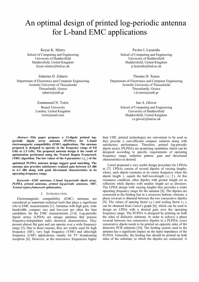
II. PLPDA DESIGN PROCEDURE There are various parameters of the PLPDA which need to be taken into consideration while designing the antenna. The most significant parameters for PLPDA design are the length of the dipoles and the spacing between them. Both of these parameters depend on the scaling factor ( ) and the spacing factor ( ). An LPDA designing starts by determining the value of and , assuming that the antenna is in free space. The value for scaling factor and spacing factor could be determined through the graph introduced by Carrel in [5]:
Figure 1. Carrel's graph to determine the gain from scaling factor versus spacing factor curve. The optimum values for and can be determined using the intersection points obtained on the line 0.243 0.051 depending on the desired gain (G). Furthermore, the number of dipoles N required for the antenna, can be evaluated by solving the following expression:
log1 1log
sBN
(1)
where, sB is the structure bandwidth which can be calculated as:
.uppers ar
lower
fB B
f
(2)
2 41.1 7.7 (1 )1arB
(3)
where, arB is the active region bandwidth of the PLPDA. Since, the antenna performance at the lowest frequency ( lowerf) depends on the length of the longest element, this value is substituted in (4):
112 lower
cLf
(4)
where, c is the speed of light. The lengths of consecutive dipoles can be determined by:
1 .n nL L (5)
The spacing between the longest dipole and its consecutive dipole can be calculated by:
1 21 2
4.2 1
L LS S
(6)
1 .n nS S (7)
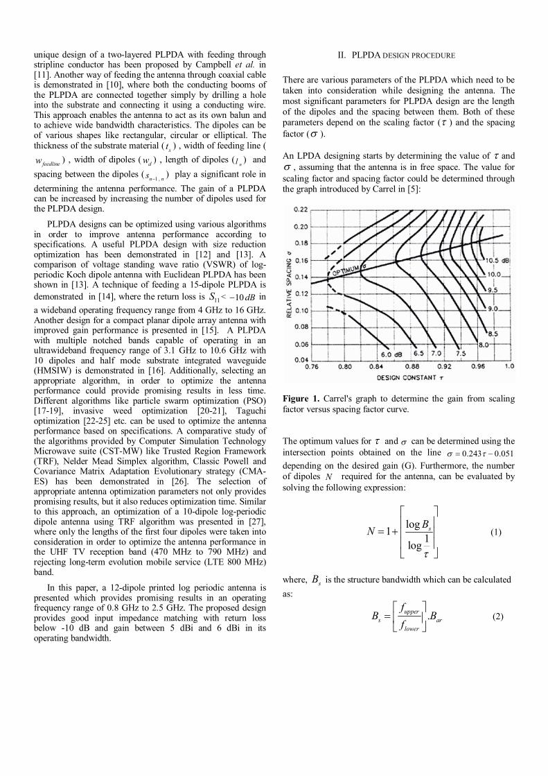
The above equations from (1) to (7) are used to calculate the antenna design for an LPDA in free space conditions. However, the antenna design might change in case of PLPDA because the dielectric constant of the substrate needs to be considered while designing the antenna. Figure 2 shows a basic geometry of PLPDA with n-dipoles which is designed using equations (1) to (7), taking into consideration the effect of the dielectric constant of the substrate. This paper presents a 12-dipole PLPDA that operates between 0.8 GHz to 2.5 GHz. The dimensions of the antenna are 150 160 1mm mm mm (length x breadth x height). The dipoles of the proposed PLPDA are arranged in such a way that the width of the five short dipoles at the front end of the antenna are equal (
12 11 10 9 8w w w w w ), whereas the remaining dipoles have varying width until the longest dipole. The length of the dipoles keeps increasing gradually from the shortest dipole at the front end of the antenna until the longest dipole at the rear end of the antenna. The proposed antenna is printed on FR4 substrate (with dielectric constant r = 4.3) and 1 mm thickness. The width of the feeding line is 1 mm, which is printed on both the sides of the substrate in order to feed the dipoles, thereby providing 180-degree phase reversal.
Figure 2. Basic geometry of PLPDA.
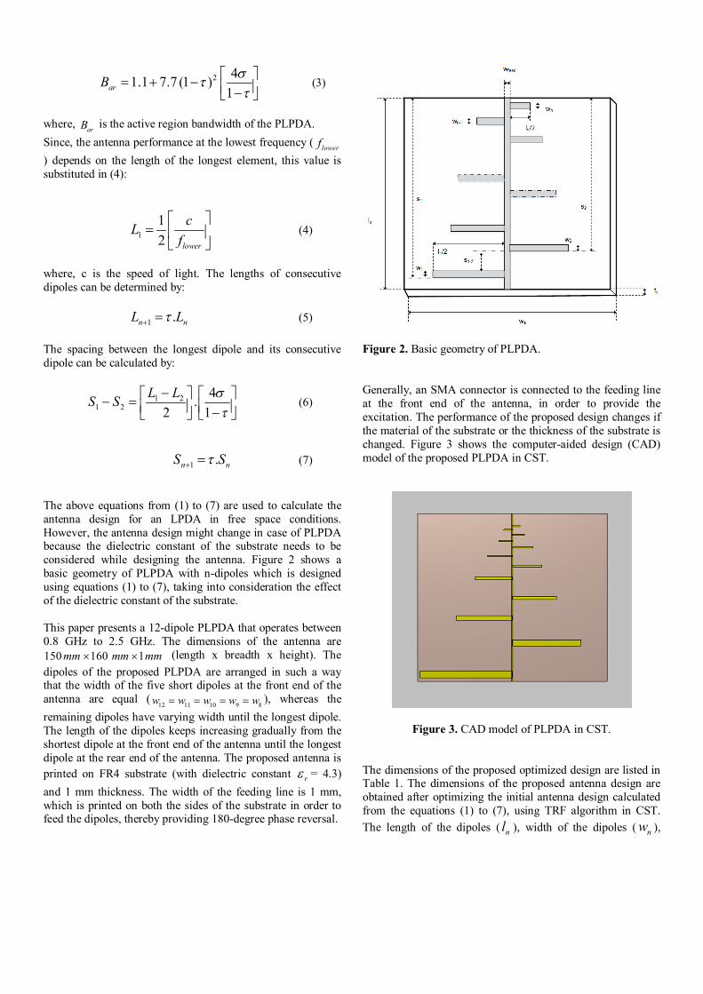
Generally, an SMA connector is connected to the feeding line at the front end of the antenna, in order to provide the excitation. The performance of the proposed design changes if the material of the substrate or the thickness of the substrate is changed. Figure 3 shows the computer-aided design (CAD) model of the proposed PLPDA in CST.
Figure 3. CAD model of PLPDA in CST. The dimensions of the proposed optimized design are listed in Table 1. The dimensions of the proposed antenna design are obtained after optimizing the initial antenna design calculated from the equations (1) to (7), using TRF algorithm in CST. The length of the dipoles ( nl ), width of the dipoles ( nw ),
spacing between the dipoles ( 1n nS S ), width of the feed
line ( feedw ) are the parameters that were considered for the optimization. The optimization goals with respective weights are listed in Table 2. Table 1. Dimensions of the proposed PLPDA antenna design.
Dipoles (n) Length of
dipoles (ln) in mm
Width of dipoles (wn) in mm
Spacing (Sn-1 - Sn )
in mm
1 156.3 5.8 3.3 2 115.8 5.3 28.5 3 94.9 3.8 23.0 4 74.1 2.8 18.3 5 62.2 2.7 17.5 6 49.3 1.5 11.3 7 41.9 1.0 9.2 8 34.8 0.9 7.5 9 22.8 0.9 5.7
10 20.5 0.9 5.5 11 14.6 0.9 4.3 12 12.8 0.9 3.5
In Table 1, ( 0 1S S ) is the distance between the longest dipole and the edge of the substrate. The dimensions of the substrate is 150 160 1mm mm mm . The width of the feed (
feedw ) is 1 mm.
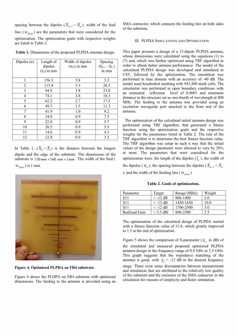
Figure 4. Optimized PLPDA on FR4 substrate. Figure 4 shows the PLDPA on FR4 substrate with optimized dimensions. The feeding to the antenna is provided using an
SMA connector, which connects the feeding line on both sides of the substrate.
III. PLPDA SIMULATIONS AND OPTIMIZATION
This paper presents a design of a 12-dipole PLPDA antenna, whose dimensions were calculated using the equations (1) to (7) and, which was further optimized using TRF algorithm in order to obtain better antenna performance. The model of the calculated PLPDA design was developed and simulated in CST, followed by the optimization. The simulation was performed in time domain with an accuracy of -40 dB. The model used hexahedral meshing with 943,500 mesh cells. The simulation was performed in open boundary conditions with an estimated reflection level of 0.0001 and minimum distance to the structure set as one-fourth of wavelength at 800 MHz. The feeding to the antenna was provided using an excitation waveguide port attached to the front end of the antenna. The optimization of the calculated initial antenna design was performed using TRF algorithm, that generated a fitness function using the optimization goals and the respective weights for the parameters listed in Table 2. The role of the TRF algorithm is to determine the best fitness function value. The TRF algorithm was setup in such a way that the initial values of the design parameter were allowed to vary by 20% at most. The parameters that were considered for the optimization were: the length of the dipoles ( nl ), the width of
the dipoles ( nw ), the spacing between the dipoles ( 1n nS S ), and the width of the feeding line ( feedw ).
Table 2. Goals of optimization.
Parameter Target Range (MHz) Weight S11 < -12 dB 800-1400 3.0 S11 < -12 dB 1450-1650 10.0 S11 < -12 dB 1700-2500 3.0 Realized Gain > 3.5 dBi 800-2500 2.5 The optimization of the calculated design of PLPDA started with a fitness function value of 15.8, which greatly improved to 1.5 at the end of optimization. Figure 5 shows the comparison of S-parameter ( 11S in dB) of the simulated and measured proposed optimized PLPDA antenna design in the frequency range of 0.8 GHz to 2.5 GHz. This graph suggests that the impedance matching of the antenna is good, with 11S < -12 dB in the desired frequency range. There exist some discrepancies between measurement and simulation that are attributed to the relatively low quality of the substrate and the omission of the SMA connector in the simulation for reasons of simplicity and faster simulation.
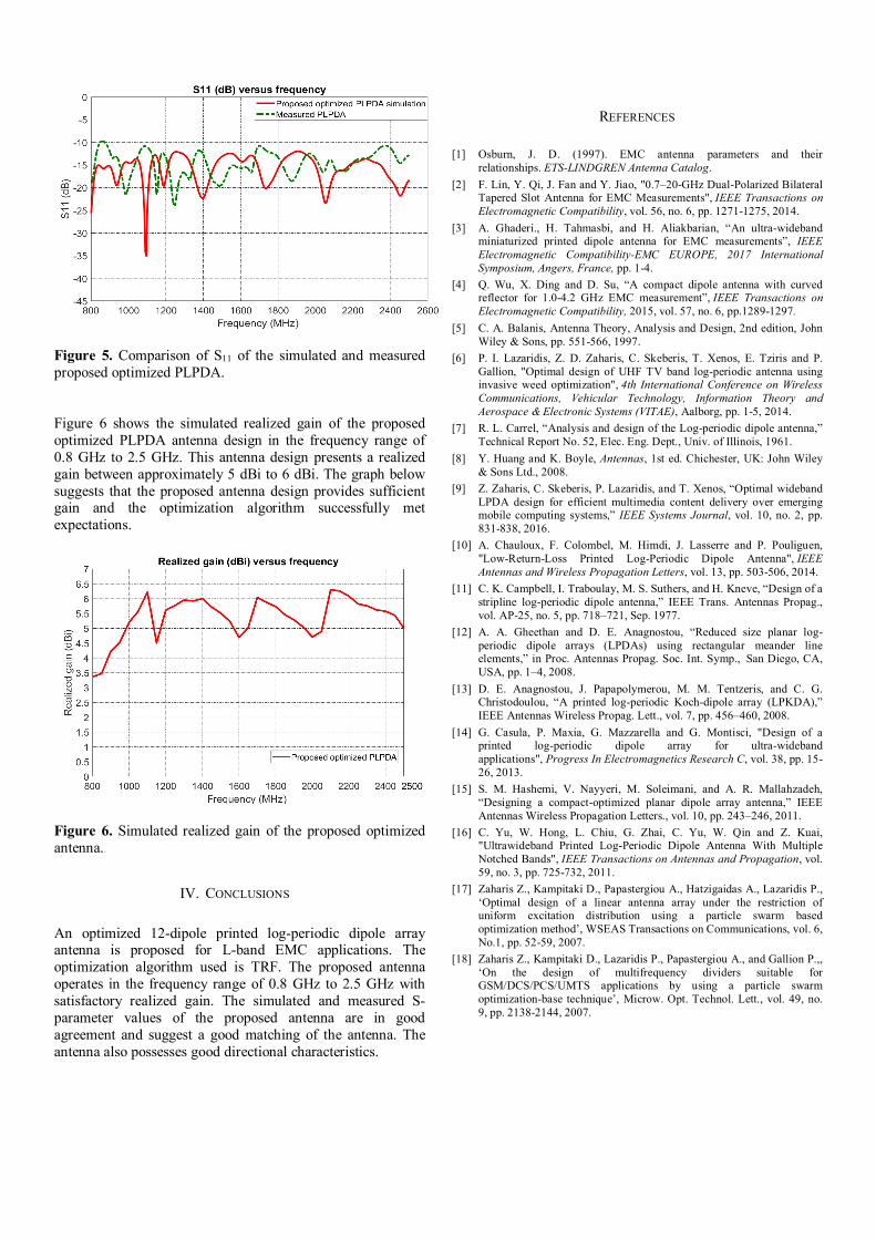
Figure 5. Comparison of S11 of the simulated and measured proposed optimized PLPDA.
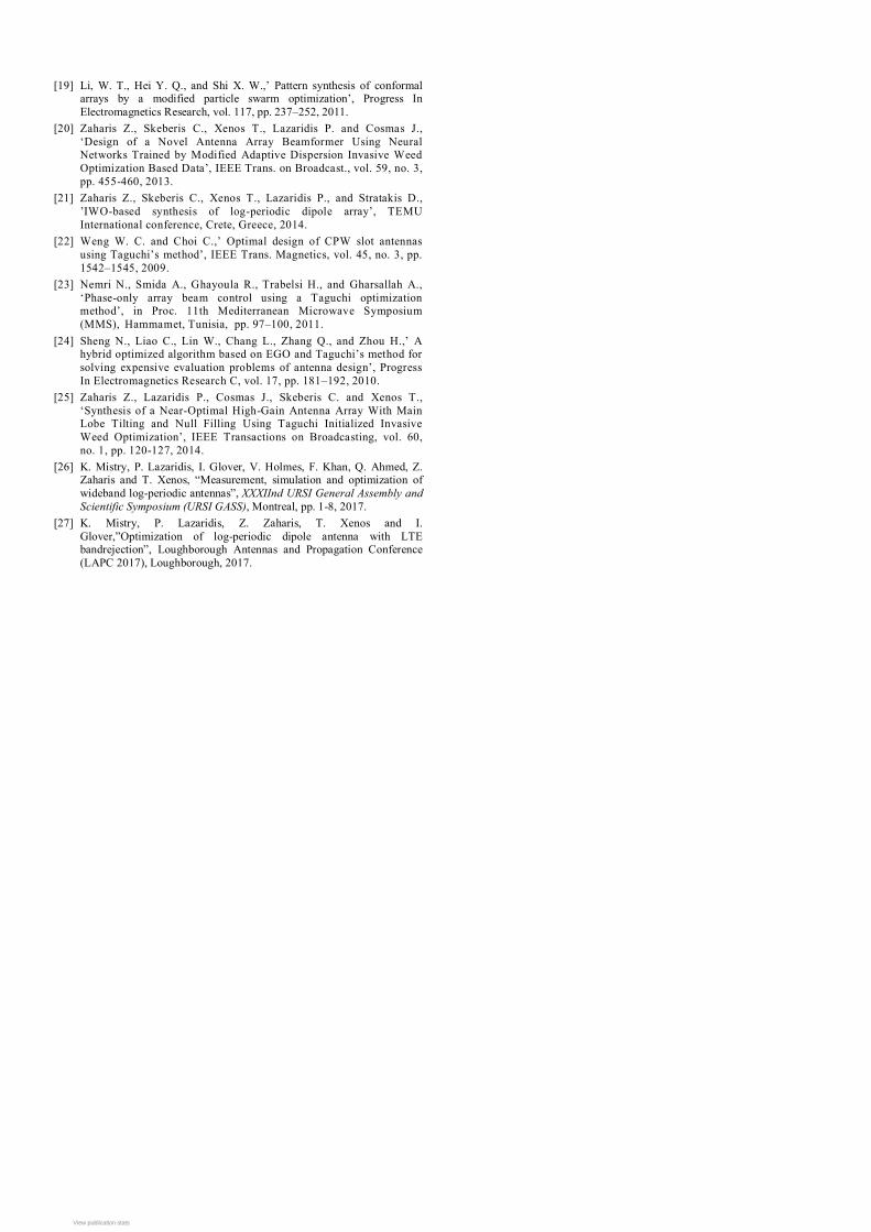
Figure 6 shows the simulated realized gain of the proposed optimized PLPDA antenna design in the frequency range of 0.8 GHz to 2.5 GHz. This antenna design presents a realized gain between approximately 5 dBi to 6 dBi. The graph below suggests that the proposed antenna design provides sufficient gain and the optimization algorithm successfully met expectations.
Figure 6. Simulated realized gain of the proposed optimized antenna.
IV. CONCLUSIONS An optimized 12-dipole printed log-periodic dipole array antenna is proposed for L-band EMC applications. The optimization algorithm used is TRF. The proposed antenna operates in the frequency range of 0.8 GHz to 2.5 GHz with satisfactory realized gain. The simulated and measured S-parameter values of the proposed antenna are in good agreement and suggest a good matching of the antenna. The antenna also possesses good directional characteristics.
REFERENCES
[1] Osburn, J. D. (1997). EMC antenna parameters and their relationships. ETS-LINDGREN Antenna Catalog.
[2] F. Lin, Y. Qi, J. Fan and Y. Jiao, "0.7–20-GHz Dual-Polarized Bilateral Tapered Slot Antenna for EMC Measurements", IEEE Transactions on Electromagnetic Compatibility, vol. 56, no. 6, pp. 1271-1275, 2014.
[3] A. Ghaderi., H. Tahmasbi, and H. Aliakbarian, “An ultra-wideband miniaturized printed dipole antenna for EMC measurements”, IEEE Electromagnetic Compatibility-EMC EUROPE, 2017 International Symposium, Angers, France, pp. 1-4.
[4] Q. Wu, X. Ding and D. Su, “A compact dipole antenna with curved reflector for 1.0-4.2 GHz EMC measurement”, IEEE Transactions on Electromagnetic Compatibility, 2015, vol. 57, no. 6, pp.1289-1297.
[5] C. A. Balanis, Antenna Theory, Analysis and Design, 2nd edition, John Wiley & Sons, pp. 551-566, 1997.
[6] P. I. Lazaridis, Z. D. Zaharis, C. Skeberis, T. Xenos, E. Tziris and P. Gallion, "Optimal design of UHF TV band log-periodic antenna using invasive weed optimization", 4th International Conference on Wireless Communications, Vehicular Technology, Information Theory and Aerospace & Electronic Systems (VITAE), Aalborg, pp. 1-5, 2014.
[7] R. L. Carrel, “Analysis and design of the Log-periodic dipole antenna,” Technical Report No. 52, Elec. Eng. Dept., Univ. of Illinois, 1961.
[8] Y. Huang and K. Boyle, Antennas, 1st ed. Chichester, UK: John Wiley & Sons Ltd., 2008.
[9] Z. Zaharis, C. Skeberis, P. Lazaridis, and T. Xenos, “Optimal wideband LPDA design for efficient multimedia content delivery over emerging mobile computing systems,” IEEE Systems Journal, vol. 10, no. 2, pp. 831-838, 2016.
[10] A. Chauloux, F. Colombel, M. Himdi, J. Lasserre and P. Pouliguen, "Low-Return-Loss Printed Log-Periodic Dipole Antenna", IEEE Antennas and Wireless Propagation Letters, vol. 13, pp. 503-506, 2014.
[11] C. K. Campbell, I. Traboulay, M. S. Suthers, and H. Kneve, “Design of a stripline log-periodic dipole antenna,” IEEE Trans. Antennas Propag., vol. AP-25, no. 5, pp. 718–721, Sep. 1977.
[12] A. A. Gheethan and D. E. Anagnostou, “Reduced size planar log-periodic dipole arrays (LPDAs) using rectangular meander line elements,” in Proc. Antennas Propag. Soc. Int. Symp., San Diego, CA, USA, pp. 1–4, 2008.
[13] D. E. Anagnostou, J. Papapolymerou, M. M. Tentzeris, and C. G. Christodoulou, “A printed log-periodic Koch-dipole array (LPKDA),” IEEE Antennas Wireless Propag. Lett., vol. 7, pp. 456–460, 2008.
[14] G. Casula, P. Maxia, G. Mazzarella and G. Montisci, "Design of a printed log-periodic dipole array for ultra-wideband applications", Progress In Electromagnetics Research C, vol. 38, pp. 15-26, 2013.
[15] S. M. Hashemi, V. Nayyeri, M. Soleimani, and A. R. Mallahzadeh, “Designing a compact-optimized planar dipole array antenna,” IEEE Antennas Wireless Propagation Letters., vol. 10, pp. 243–246, 2011.
[16] C. Yu, W. Hong, L. Chiu, G. Zhai, C. Yu, W. Qin and Z. Kuai, "Ultrawideband Printed Log-Periodic Dipole Antenna With Multiple Notched Bands", IEEE Transactions on Antennas and Propagation, vol. 59, no. 3, pp. 725-732, 2011.
[17] Zaharis Z., Kampitaki D., Papastergiou A., Hatzigaidas A., Lazaridis P., ‘Optimal design of a linear antenna array under the restriction of uniform excitation distribution using a particle swarm based optimization method’, WSEAS Transactions on Communications, vol. 6, No.1, pp. 52-59, 2007.
[18] Zaharis Z., Kampitaki D., Lazaridis P., Papastergiou A., and Gallion P.,, ‘On the design of multifrequency dividers suitable for GSM/DCS/PCS/UMTS applications by using a particle swarm optimization-base technique’, Microw. Opt. Technol. Lett., vol. 49, no. 9, pp. 2138-2144, 2007.
[19] Li, W. T., Hei Y. Q., and Shi X. W.,’ Pattern synthesis of conformal arrays by a modified particle swarm optimization’, Progress In Electromagnetics Research, vol. 117, pp. 237–252, 2011.
[20] Zaharis Z., Skeberis C., Xenos T., Lazaridis P. and Cosmas J., ‘Design of a Novel Antenna Array Beamformer Using Neural Networks Trained by Modified Adaptive Dispersion Invasive Weed Optimization Based Data’, IEEE Trans. on Broadcast., vol. 59, no. 3, pp. 455-460, 2013.
[21] Zaharis Z., Skeberis C., Xenos T., Lazaridis P., and Stratakis D., ’IWO-based synthesis of log-periodic dipole array’, TEMU International conference, Crete, Greece, 2014.
[22] Weng W. C. and Choi C.,’ Optimal design of CPW slot antennas using Taguchi’s method’, IEEE Trans. Magnetics, vol. 45, no. 3, pp. 1542–1545, 2009.
[23] Nemri N., Smida A., Ghayoula R., Trabelsi H., and Gharsallah A., ‘Phase-only array beam control using a Taguchi optimization method’, in Proc. 11th Mediterranean Microwave Symposium (MMS), Hammamet, Tunisia, pp. 97–100, 2011.
[24] Sheng N., Liao C., Lin W., Chang L., Zhang Q., and Zhou H.,’ A hybrid optimized algorithm based on EGO and Taguchi’s method for solving expensive evaluation problems of antenna design’, Progress In Electromagnetics Research C, vol. 17, pp. 181–192, 2010.
[25] Zaharis Z., Lazaridis P., Cosmas J., Skeberis C. and Xenos T., ‘Synthesis of a Near-Optimal High-Gain Antenna Array With Main Lobe Tilting and Null Filling Using Taguchi Initialized Invasive Weed Optimization’, IEEE Transactions on Broadcasting, vol. 60, no. 1, pp. 120-127, 2014.
[26] K. Mistry, P. Lazaridis, I. Glover, V. Holmes, F. Khan, Q. Ahmed, Z. Zaharis and T. Xenos, “Measurement, simulation and optimization of wideband log-periodic antennas”, XXXIInd URSI General Assembly and Scientific Symposium (URSI GASS), Montreal, pp. 1-8, 2017.
[27] K. Mistry, P. Lazaridis, Z. Zaharis, T. Xenos and I. Glover,”Optimization of log-periodic dipole antenna with LTE bandrejection”, Loughborough Antennas and Propagation Conference (LAPC 2017), Loughborough, 2017.
View publication statsView publication stats