Embed Size (px)
Citation preview

An optical triangulation method for non-contactprofile measurement
Sanjeev Kumar Prabhat Kumar Tiwari S.B.ChaudhuryResearcher, Researcher, Head ,System Integration
Automation Division, Automation Division, Automation Division,TATA STEEL, India TATA STEEL,India TATA STEEL,India
sanjeevk@aut. tatasteel. com prabhat@aut. tatasteel. com sbcl @aut. tatasteel. com
Abstract- In this paper we present a triangulation based have some advantages over mechanical probes namely inrange sensor for non-contact profile measurement. The sensor providing higher speed of operation and by doing themeasures distances and orientations of objects and surfaces,based on the triangulation principle. This method is highly measurement of c act [2].
indeendet frmopicalsurfce poperies nd alows In the recent years, 2D laser range finders mounted onIndependent from optical surface properties and allowsmoierbt aebcm aiusignificant range measurements. Then a polynomial mobile robots have become very common for various robot
approximation based direct calibration method of this sensor navigation tasks. Theory provide in real time accurateis described. Next we present a prototype of the measuring range measurements in large angular fields at a fixedsystem where the object is illuminated with laser sheet of light height above the ground plane, and enable robots toand viewed with the camera. The illumination angle, viewingangle and baseline between laser source and camera gives the perform more cf en a wdrnge of ts by fusIntriangulation geometry from which the depth information and image data from the camera mounted on robots [1] [5]. In3D shape of the object is to be measured. A simple method for order to effectively use the data from the camera and laserobtaining depth information using least square method is range finder, it is important to know their relative positionexplained next. A comparison with range sensor results with and orientation from each other, which affects thestandard calibrated results is performed to judge the geometric interpretation of its measurements. Also thesesuitablity and accuracy of the system.
sensors have very useful applications in areas such as
Index Terms- automatic dimensional measurement computer vision based automatic control systems in microsystem, calibration, Laser range finder, optical triangulation. robotics [4].
The calibration of each of these geometric sensors canbe decomposed into internal calibrations parameters and
I. INTRODUCTION external parameters [6]. The external calibrationparameters are the position and orientation of the sensor
During the past decade the centuries old concept of relative to some fiducially coordinate system. The internalabsolute range measurement by means of optical parameters, such as the calibration matrix of a camera,
triangulation has experienced a dramatic increase in use. affect how the sensor samples the scene. This paperThis has been due to the availability of the laser diode as a assumes the internal sensor calibration is known, andlight source and the increasing need for accurate non- focuses on the external calibration. There has been a greatcontact range sensing in a variety of applications. In this deal of work on calibration for laser scanners, which are thepaper our main area of application is the dimension parts of active vision systems that project a point or a stripemeasurement of standard hot/cold rolled products in steel which is then viewed by the camera. Finding the geometricmanufacturing industries like TMT bars, angles, rails, relationship between the laser scanner and the camera isbeams, channels, flats etc. The other applications include vital for creating metric depth estimations to build texturalauto bodies on the production line [7], profiling of turbine 3D models. Given the camera intrinsic parameters and itsblades [8], and high speed profiling of joints and beads for relative location with respect to the laser plane, the positionactive control of welding processes [9]. A rapidly growing of the corresponding point in the laser stripe can bearea is detailed profiling of complex 3-D shapes to produce estimated by triangulation. Finally, these can becomputerized databases for reverse engineering or other transformed into 3D coordinates by incorporating thepurposes [10]. known motion ofthe object relative to the laser plane.The development of robots with high flexibility of In section II we discuss the basic principle of laser
functions is deeply dependent from the improvement in triangulation and briefly describe the hardware used for thesensorial systems. The robotic sensors usually used in test setup. Section III describes the calibration method usedmeasuring distance and orientations are based either on and in last section we discuss the measurement resultsultrasonic, microwaves or optical techniques. These sensors obtained from trial experiments.
1-4244-0726-5/06/$20.OO '2006 IEEE 2878
Authorized licensed use limited to: HEFEI UNIVERSITY OF TECHNOLOGY. Downloaded on November 18, 2008 at 08:39 from IEEE Xplore. Restrictions apply.
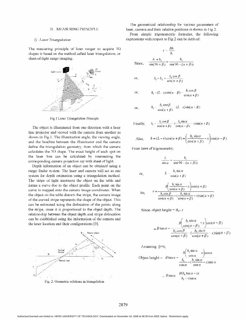
The geometrical relationship for various parameters ofII. MEASURING PRINCIPLE laser, camera and their relative positions is shown in Fig 2.
From simple trigonometric formulas, the following1) Laser Triangulation expressions with respect to Fig.2 can be derived:
The measuring principle of laser ranger to acquire 3D r Bhshapes is based on the method called laser triangulation, or bisheet-of-light range imaging. b_ +b2 bo
Since, sin(90 + /3) sin(90 - (ao +/3))
Light sFwcT
Sensor
or, b+b 0cos1W 2,, ;cos(oa +,B)
/ or, b±+(L-s)sin(a±+/) b0cosCos a ±/
7 / X-~ or, b cos(o +) -(L s)sin(a /
Fig 1 Laser Triangulation PrincipleFinally, b = b0cosf_ bo siIU _s)sin(a +3)
The object is illuminated from one direction with a laser cos(a±f)+ cos(a +)line projector and viewed with the camera from another asshown in Fig. 1. The illumination angle, the viewing angle, Also, h = (L - s) cos(a +,/) = r bo sina js cos(a +,/)and the baseline between the illuminator and the camera Acos(a +,/) )define the triangulation geometry, from which the camera From laws of trigonometry,calculates the 3D shape. The exact height of each spot onthe laser line can be calculated by intersecting the L bocorresponding camera projection ray with sheet of light. sino sin(90 - (a ± /3))
Depth information of an object can be obtained using arange finder system. The laser and camera will act as one L =
bo sin asystem for depth estimation using a triangulation method. or,cos( +The stripe of light intersects the object on the table andforms a curve due to the object profile. Each point on the B boSina s cos(a±+/)curve is mapped onto the camera image coordinates. When r = cos(a±+ )the object on the table distorts the stripe, the camera image So, bocos/3 bo sin a -s)sin(a +of the curved stripe represents the shape of the object. This cos(a +,/) cos(a +,/)can be estimated using the dislocation of the points alongthe stripe, since it is proportional to the object depth. The Since, object height = Ro- rrelationship between the object depth and stripe dislocationcan be established using the information of the camera and bbsinathe laser location and their configurations [3]. B -s cos(a +/)
B tana - b0 cos(oc + ,Bi)bo cos, bo sinocf:!Sen.sor Ssane i(- )sn(as + ,cos(ao+,) cos(ac+,)
L
Assuming =sO,Optica iCentre ;______ __ x BsjJCoscaB-
b= b, Object height Btanba b,Qptical am's_b --( bsia -s)sina
K r ~~~~~~~~~~~~~~Btanao_B(botanao-s)bo ± stanao
Fig. 2. Geometric relations in triangulation
2879
Authorized licensed use limited to: HEFEI UNIVERSITY OF TECHNOLOGY. Downloaded on November 18, 2008 at 08:39 from IEEE Xplore. Restrictions apply.

Fig.3.Therefore, The location of the laser spot image center can be
s sec2 a determined by the following methods:Object height b+ stan a Position = (a+b)/2 or (m+n)/2
or2) IVP ranger M50 camera hardware COG (center-of-gravity).
The core of the IVP ranger camera is the smart vision E xI(x)sensor M12 and the Intel StrongArm processor [12]. The Peak_Position I)architecture is built of three main components: the M12sensor, the processor and the high-speed serial interface(HSSI) module. The sensor has two parallel 32 bit widebuses, one is used for feeding instructions from the Strong Maximum
Arm processor, and one is used for outputting data over theHSSI-link. The HSSI link can send and receive data at highspeed (Max. 330 Mbit/s) to the PC. In addition to the HSSIinterface there is a RS232 serial port and 5 digital in and 1digital output on the camera. The digital I/O can be used tosynchronize the measurements with the movement of theobject or the sensor system. Fig.3. Selection of laser impact positionThe Camera dimensions are 97 x 50 x 50 (1 x h x w) mm
and the unit is threaded for standard 1" C lenses. Thhe .. .and t u ita f sdThe laser line will form a distinct light peak distributedCamera unit supports power supply between 12 and24VDCa Thet disupportance wersupplbetween the2Cand tover a number of pixels within the sensor column. Themaximum 50e mestersewithtwisnthedCpair SAhe cabler i
center of this peak will be defined as the impact position of
Cameraxmode M50 hswitha5t2xs536 paixe HsnSor car the laser line on that sensor column. The 3D algorithms,Camera model M50 has a 512x1536 pixel sensor area.HoTradHraTr ssthehlst aclt h
The processing to convert the image of the laser line into HorThr and HorMaxThr, uses thresholds to calculate thea vector with 3D shape data is very time consuming. IVp impact position while the Hi3D algorithm uses the center-smart vision sensor with built-in RISC processors, the of-gravity (COG) method. The usage of thresholdsconversion from 2D images to 3D shape data can be done increases the height resolution of the measurement, withalready on the sensor chip. The image of the laser line one threshold a '/2 - pixel resolution can be obtained andnever leaves the sensor chip, only the calculated 3D data with two thresholds a 1/4 - pixel resolution can be obtained.itself; this is the key to the extremely high speed of IVP The usage of COG gives an increase in height direction,ranger. typically 1/10 - pixel resolution. The integration time isThe IVP smart vision sensor M12 has a width and height defined as the time used to collect light on the sensor for
resolution of up to 1536 x 512 pixels. With the one profile sample. With a fixed light intensity from thesophisticated ranger 3D profiling software it is possible to laser, two different integration times will result in differentobtain 3d data with a resolution of up to 1/5120 of the intensity values on the sensor.height measurement range. The result from one measurement (scan) is a rangeThe laser used for our experiments is a line projector profile of 3D-values (rangels) and optionally also an
with visible green light with 35 mW power. The laser has a l . .imanually adjustable focus between 10 mm and 4000 mm. intenity pfe ofrintensity-valu the IVPsrangalgorithms use parameters to set all the measurement
3) Aleasuring technique techniques described above. The behaviour of the selectedalgorithm is defined by the current parameter setting for
All standard algorithms work with the laser line aligned that particular algorithm at the time when the algorithm ishorizontally with the rows on the sensor. That means, when started.viewing an image of a flat object illuminated with the lasera flat horizontal laser line appears in the image. The 4) Camera Softwarealgorithms support region of interest windowing, andthereby height measurement range can be traded for speed. The profiling software in the camera consists ofUsing a smaller region on the sensor enables measurements algorithms for 3D profiling, data buffer options andat a higher profiling rate. The ROI-height (Region of possibilities to synchronize the 3D measurement withInterest) is defined by selecting the number of sensor rows external signals.to be use. The standard algorithms are: Horizontal thresholding
The basic function of all the measurement algorithms is (HorThr), Horizontal maximum and thresholdingto compute the impact position of the laser line for all (HorMaxThr), High resolution range (Hi3D) and Image.columns on the sensor. The light intensity distribution from The three first are 3D-range algorithms and the last one is athe laser line along a sensor column can be described as in grey scale algorithm.
2880
Authorized licensed use limited to: HEFEI UNIVERSITY OF TECHNOLOGY. Downloaded on November 18, 2008 at 08:39 from IEEE Xplore. Restrictions apply.
The horizontal thresholding algorithm is the fastest ofthe standard algorithms. The impact position of the laser in 2
each column is computed as described in section above.Two thresholds may be used to achieve higher rangeresolution. A (3xl) median filter can be applied to therange data to smoothen the data, and to reduce laser speckleinfluences. The acquisition speed of the HorThr algorithmis dependent on the current setting of the algorithm and thesynchronization parameters. 0 Tag: 1772 1535
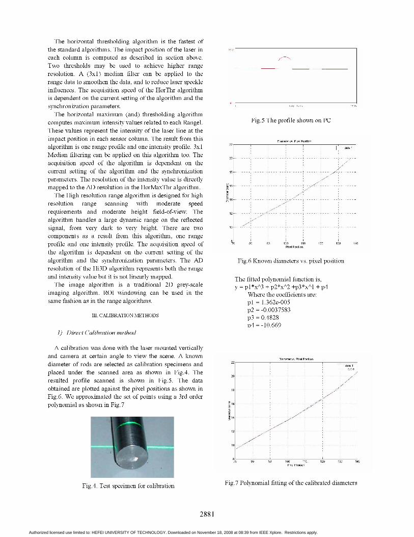
The horizontal maximum (and) thresholding algorithmcomputes maximum intensity values related to each Rangel. Fig.5 The profile shown on PCThese values represent the intensity of the laser line at theimpact position in each sensor column. The result from this Diameter vs. Pixel Position
22algorithm is one range profile and one intensity profile. 3xlMedian filtering can be applied on this algorithm too. The
20acquisition speed of the algorithm is dependent on thecurrent setting of the algorithm and the synchronization 18 ...... ......
parameters. The resolution of the intensity value is directlymapped to the AD resolution in the HorMaxThr algorithm.6The High resolution range algorithm is designed for high*
resolution range scanning with moderate speedrequirements and moderate height field-of-view. The 12
algorithm handles a large dynamic range on the reflectedsignal, from very dark to very bright. There are twocomponents as a result from this algorithm, one rangeprofile and one intensity profile. The acquisition speed of 70 80 90 100i P *t* 110 120 130 140the algorithm is dependent on the current setting of thealgorithm and the synchronization parameters. The AD Fig.6 Known diameters vs. pixel positionresolution of the Hi3D algorithm represents both the rangeand intensity value but it is not linearly mapped. The fitted polynomial function is,The image algorithm is a traditional 2D grey-scale y pl*xxA3 + p2*xA2 +p3*xAl + p4
imaging algorithm. ROI windowing can be used in the Where the coefficients are:same fashion as in the range algorithms. pl = 1.362e-005
p2 = -0.0037583III. CALIBRATION METHODS p3 = 0.4828
p4 = -10.6691) Direct Calibration method
A calibration was done with the laser mounted verticallyand camera at certain angle to view the scene. A known Diameter vs, Pixel Position
22v P o
diameter of rods are selected as calibration specimens and data 1cubic
placed under the scanned area as shown in Fig.4. The20 ...... ><
resulted profile scanned is shown in Fig.5. The dataobtained are plotted against the pixel positions as shown inFig.6. We approximated the set of points using a 3rd orderpolynomial as shown in Fig.7 X
E
702 809110 11 20 10 4.~~~~~~~~~~~~~~~~~~~~~~~~~~~~~~~1
s ~~~~~~~~~~~~~~~~~~~~~~~~~~~~~~~~~~~Pixel Position
Fig.4. Tetspecimn for caibrationFig.7 Polynomial fitting of the calibrated diameters
2881
Authorized licensed use limited to: HEFEI UNIVERSITY OF TECHNOLOGY. Downloaded on November 18, 2008 at 08:39 from IEEE Xplore. Restrictions apply.
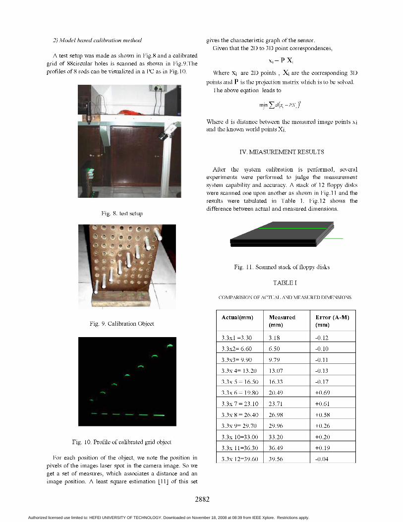
2) Model based calibration method gives the characteristic graph ofthe sensor.Given that the 2D to 3D point correspondences,
A test setup was made as shown in Fig.8 and a calibrated P Xgrid of 88circular holes is scanned as shown in Fig.9.The I Pprofiles of 8 rods can be visualized in a PC as in Fig.1O. Where xi are 2D points , Xi are the corresponding 3D
points and P is the projection matrix which is to be solved.The above eqation leads to
minZ d(x PXj)
Where d is distance between the measured image points xiand the known world points Xi.
IV. MEASUREMENT RESULTS
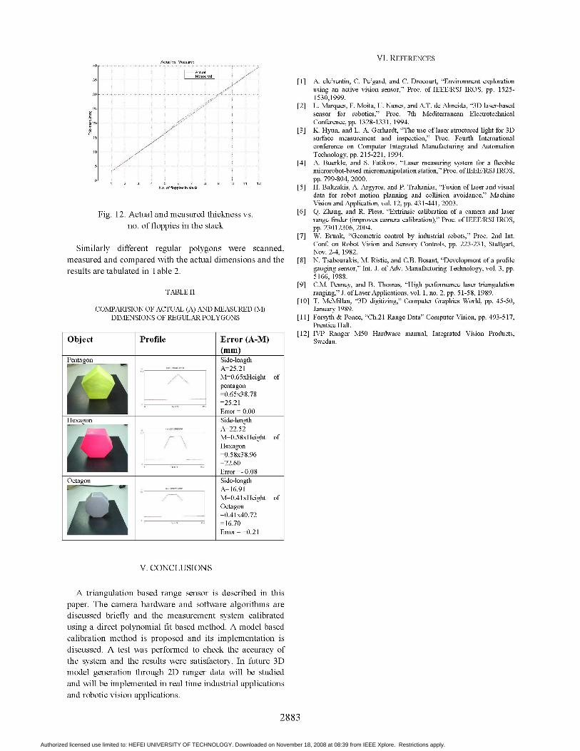
After the system calibration is performed, severalexperiments were performed to judge the measurementsystem capability and accuracy. A stack of 12 floppy diskswere scanned one upon another as shown in Fig. 11 and theresults were tabulated in Table 1. Fig.12 shows thedifference between actual and measured dimensions.
Fig. 8. test setup
Fig. 11. Scanned stack of floppy disks
TABLE I
COMPARISION OF ACTUAL AND MEASURED DIMENSIONS
Actual(mm) Measured Error (A-M)Fig. 9. Calibration Object (mm) (mm)
3.3xl=3.30 3.18 -0.12
3.3x2= 6.60 6.50 -0.10
3.3x3= 9.90 9.79 -0.11
3.3x4= 13.20 13.07 -0.13
3.3x 5 = 16.50 16.33 -0.17
3.3x 6= 19.80 20.49 +0.69
3.3x 7 =23.10 23.71 +0.61
3.3x 8 =26.40 26.98 +0.58
3.3x 9= 29.70 29.96 +0.26
3.3x 10=33.00 33.20 +0.20Fig. 10. Profile ofcalibrated grid objectllll
l3.3x 11=36.30 l36.49 l+0.19lFor each position of the object, we note the position in |3.3x 12=39.60 l39.56 |-0.04l
pixels of the images laser spot in the camera image. So weget a set of measures, which associates a distance and animage position. A least square estimation [11] of this set
2882
Authorized licensed use limited to: HEFEI UNIVERSITY OF TECHNOLOGY. Downloaded on November 18, 2008 at 08:39 from IEEE Xplore. Restrictions apply.
I1 A. cle'rentin, C. Pe'gard, and C. Drocourt, "Environment explorationusing an active vision sensor," Proc. of IEEE/RSJ IROS, pp. 1525-1530,1999.
25 ...[2] L. Marques, F. Moita, U. Nunes, and A.T. de Almeida, '3D) laser-basedE ~~~~~~~~~~~~~~~~~sensor for robotics," Proc. 7th Mediterranean Electrotechnical20 ~~~~~~~~~~~~~~~~Conference,pp. 1328-1331, 1994.
[3] K. Hyun, and L. A. Gerhardt, "The use of laser structured light for 3Dsurface measurement an inspection," Proc. Fourth Internationalconference on Computer Integrated Manufacturing and AutomationTechnology, pp. 215-221, 1994.
[4] A. Buerkle, and S. Fatikow, 'Laser measuring system for a flexiblemyicrorobot-based mnicromanipulation station," Proc. of IEEE/RSJ IROS,
ol ~~~~~~~~~~~~~~~~~pp.799-804, 2000.No. of floppies in stack [5] H. Baltzakis, A. Argyros, and P. Trahanias, 'Fusion of laser and visual
data for robot motion planning and collision avoidance," MachineVision and Application, vol. 12, pp. 43 1-441, 2003.
Fig. 12. Actual and measured thickness vs. [6] Q. Zhang, and R. Pless, 'Extrinsic calibration of a camera and laserrange finder (improves camera calibration)," Proc. of IEEE/RSJ IROS,
no. of floppies in the stack pp. 23012306, 2004.[7] W. Brunk, 'Geometric control by industrial robots," Proc. 2nd Int.
Smlry different regular polygons were scanned, Conf on Robot Vision and Sensory Controls, pp. 223-231, Stuttgart,Similarly ~~~~~~~~~~~~~~Nov.2-4, 1982.
measured and compared with the actual dimensions and the [8] N. Tsabourakis, M. Ristic, and C.B. Besant, 'Development of a profileresults are tabulated in Table 2. gauging sensor," Int. J. of Adv. Manufacturing Technology, vol. 3, pp.
5166, 1988.[9] C.M. Penney, and B. Thomas, 'High performance laser triangulation
TABLE II ranging," J. of Laser Applications, vol. 1, no. 2, pp. 5 1-58, 1989.[10] T. McMillan, '3D) digitizing," Computer Graphics World, pp. 45-50,
COMPARISION OF ACTUAL (A) AND MEASURED (M) January 1989.DIMENSIONS OF REGULAR POLYGONS [11] Forsyth & Ponce, 'Ch.2 1 Range Data" Computer Vision, pp. 493-517,
Prentice Hall.[12] IVP Ranger M50 Hardware manual, Integrated Vision Products,
Object ~ Profile Error (A-M) Swedan.(mm)
Pentagon Side-length.............. .A=25.21
M=0.65xHeight ofpentagon=0.65x38.78= 25.21Error =0.00
Hexagon Side-lengthA=22.52
N, M=0.58xHeight ofHexagon=0.58x38.96=22.60Error =- 0.08
Octagon Side-length
M=0.4lxHeight ofOctagon=0.4lx40.72~16.70Error ±0.21
V. CONCLUSIONS
A triangulation based range sensor is described in thispaper. The camera hardware and software algorithms arediscussed briefly and the measurement system calibratedusing a direct polynomial fit based method. A model based
Authorized licensed use limited to: HEFEI UNIVERSITY OF TECHNOLOGY. Downloaded on November 18, 2008 at 08:39 from IEEE Xplore. Restrictions apply.