Embed Size (px)
Citation preview
Simulation Modelling Practice and Theory 16 (2008) 1392–1414
Contents lists available at ScienceDirect
Simulation Modelling Practice and Theory
journal homepage: www.elsevier .com/locate /s impat
An ontology-based collaborative service-oriented simulationframework with Microsoft Robotics Studio�
W.T. Tsai a,*, Xin Sun a, Qian Huang a, Helen Karatza b
a Department of Computer Science and Engineering, Arizona State University, Tempe, AZ 85287-8809, United Statesb Department of Informatics, Aristotle University of Thessaloniki, 54124 Thessaloniki, Greece
a r t i c l e i n f o
Article history:Received 20 April 2008Received in revised form 7 July 2008Accepted 23 July 2008Available online 17 August 2008
Keywords:Service-oriented computingSimulation frameworkOntologyRobotics StudioModel-driven development
1569-190X/$ - see front matter � 2008 Published bdoi:10.1016/j.simpat.2008.07.007
* Corresponding author. Tel.: +1 480 727 6921; faE-mail addresses: [email protected] (W.T. Tsai), xin
1 The contents of this paper were developed under(FIPSE), US Department of Education. However, thesassume endorsement by the Federal Government.
a b s t r a c t
In Service-Oriented Architecture (SOA), the concepts that services can be discovered andapplication can be composed via service discovery bring great flexibility to applicationdevelopment [Y. Chen, W.T. Tsai, Distributed Service-Oriented Software Development, Ken-dall/Hunt, 2008, [4]]. Microsoft Robotics Studio (MSRS) is a recent initiative in applyingSOA to embedded systems and one of its key features is its 3-D simulation tool that allowsapplications to be simulated before deployment. This paper proposes an ontology-basedservice-oriented simulation framework with MSRS by adding a set of ontology systems,i.e., service ontology, workflow ontology, entity ontology, and environment ontology. Theseontology systems store relevant information useful to compose simulation applications,and items stored also cross reference to each other to facilitate reusability and rapid appli-cation composition, This paper then provides a detailed case study on a popular roboticgame Sumobot using MSRS to illustrate the key concepts and how they can support rapidsimulation development.1
� 2008 Published by Elsevier B.V.
1. Introduction
Service-Oriented Computing (SOC) using Service-Oriented Architecture (SOA) has received significant attention as majorcomputer companies such as BEA [1], CISCO [5], HP [8], IBM [10], Microsoft [21], Oracle [23], SAP [26], and Sun Microsystems[31], as well as government agencies such as US Department of Defense (DoD) [25]. SOA is characterized by loosely coupledservices, open standard interfaces, service publication, dynamic discovery of services, and dynamic composition using ser-vices discovered. SOA is being used not only for e-commerce applications, but also for embedded applications. For example,DoD is developing several large IT projects based on SOA, and some of them for real-time embedded applications. MicrosoftRobotics Studio (MSRS) [22] is another example and this is a recent initiative by Microsoft to incorporate SOA into embeddedsystem development.
SOA has its own lifecycle models and processes such as IBM Foundation Lifecycle [13], and they are different from tradi-tional software development processes. As services may be discovered and selected at runtime, it is important to verify thesenewly discovered services before they are used in applications. One important verification approach in SOA applicationdevelopment is simulation. Specifically, SOA simulation is considered a key technique for business modeling and processmanagement for IBM WebSphere applications [11]. MSRS also uses simulation to verify the robotics application.
y Elsevier B.V.
x: +1 480 965 [email protected] (X. Sun), [email protected] (Q. Huang), [email protected] (H. Karatza).
a grant from US Department of Defense and the Fund for the Improvement of Postsecondary Educatione contents do not necessarily represent the policy of the Department of Education, and you should not
W.T. Tsai et al. / Simulation Modelling Practice and Theory 16 (2008) 1392–1414 1393
As SOA computation, infrastructure, development processes, runtime environment and model-driven approach are differ-ent from traditional software, thus SOA simulation will also be different [34]. For example,
� With respect to SOA computation, SOA simulation needs to simulate services, workflows, policies, and collaboration.� With respect to SOA infrastructure, SOA simulation needs to address SOAP [28], service publishing, discovery, composition,
monitoring, deployment, and possibly even re-composition and reconfiguration. Furthermore, SOA hardware infrastruc-ture can also be simulated including visualization, HasS (Hardware as Services)/IaaS (Infrastructure as a Service) [17]or PaaS (Platform as a Service) such as in the Intel SOI (Service-Oriented Infrastructure) project [19,27].
� With respect to SOA development processes, simulation can be used in all the development phases including requirementmodeling, design, code generation, deployment, execution, and monitoring. Specifically, simulation can verify SOArequirement models, can simulate software designs, can verify the behavior and performance of services and workflows,can verify the correctness and enforcement of policies [41,42], can simulate the runtime behavior of dynamic collabora-tions [37,46] and can simulate the performance of runtime SOA monitoring. Recall that SOA software development mayfollow different development processes, for example in the IBM Foundation lifecycle model, software development andexecution are modeled in an integrated process model with the execution results providing feedback to the developmentactivities in a cyclic process. Previously, software process models consider only software development phases [34].
� SOA development is model-driven; however, SOA models may be different from traditional software models. Specifically,SOA modeling languages may need to model services, workflows, policies, SOA protocols, monitoring mechanisms. Fur-thermore, once modeled, it is desirable that these models can be used to generate simulation code. One such modelinglanguage is PSML (Process Specification and Modeling Language) [40] which can model execution processes such as work-flows, as well as policies, and can be used to generate executable code.
� The SOA simulation infrastructure can also be structured in a service-oriented manner, i.e., each component in the sim-ulation infrastructure, including the simulation engines as well as the application components and tasks, can be modeledas services or workflows using various modeling languages.
� New SOA approaches such as cloud computing [6] pose new challenges to SOA simulation. In these environments,resources owned by different organizations are distributed geographically and interconnected via wide-area networksor Internet [3]. These introduce a series of problems such as resource management and application scheduling, resourceand policy heterogeneity, fault tolerance. Simulation can play a significant role in cloud computing by simulating itsbehavior and performance. The simulation can focus on aspects such as resource scheduling, performance, interactionsamong resource brokers and users over a network.
� Another interesting approach is Software as a Service (SaaS) [30]. SaaS allows software access via networks, and softwarecan be continuously updated so that a user will always use the latest version of the software over the network. Essentially,a user may be able to make specific options about applications, and the system will return appropriate versions to fit cus-tomers’ needs. Simulation can play a role in SaaS. Before the software is uploaded in the SaaS site, it can be simulated toevaluate its performance and scalability. Different workloads and user requests can be modeled to see how the system willperform in the SaaS environment.
This paper is organized as followed: Section 2 will briefly overview the existing SOA simulation works; Section 3 intro-duces the MSRS architecture; Section 4 explains the collaborative SOA simulation framework with MSRS; Section 5 uses anexample and simulation result to illustrate the effectiveness of the proposed framework. Section 6 concludes this paper.
This paper is an extension of the paper [38] with more background introduction, and the framework is extended withcollaboration management and change management. This paper also has a new case study to illustrate the entire simulationprocess.
2. Previous SOA simulation research
Service-oriented simulation is supported by a number frameworks, including XMSF (Extensible Modeling and SimulationFramework) [2,47], the simulation grid system Cosim-Grid [20] and GridSim [3]. XMSF creates a modeling and simulationframework that utilizes a set of web-enabled technologies to facilitate modeling and simulation applications. XMSF involvesWeb/XML, Web services, and internet/networking to improve the interoperability. A significant contribution by XMSF is itsweb-based RTI (Runtime Infrastructure). Cosim-Grid is a service-oriented simulation grid based on HLA, PLM (Product Life-cycle Management) [9], and grid/web services. It applies OGSA (Open Grid Services Architecture) [33] to modeling and sim-ulation to improve HLA in terms of dynamic sharing, autonomy, fault tolerance, collaboration, and security mechanisms.GridSim is an open-source simulation framework that allows users to model and simulate the characteristics of Grid re-sources and network. It provides intensive support for grid simulation, such as workload trace simulation, jobs allocation,and network traffic simulation [3]. However, XMSF, Cosim-Grid and GridSim utilize web services as components in the com-ponent-based development without taking the full potential of SOA [29].
Other related research includes INNOV8 [12], which is an IBM training simulator. It is a three-dimensional simulation vi-deo game that puts a business person in a virtual office with the task of constructing an efficient company. SIMPROCESS [32]is a process analysis tool commonly used to support business process improvement and operations research projects. It
1394 W.T. Tsai et al. / Simulation Modelling Practice and Theory 16 (2008) 1392–1414
provides modeling, simulation and analysis capabilities. The models are used to define complex business process flows thatare represented graphically as activity diagrams. SIMPROCESS can be used in SOA by providing simulation models as a call-able service. ISTF (Interface Simulation and Testing Framework) [18] is an extensible SOA simulation tool offered by IONA,and it simulates the end-to-end distributed application scenarios and demonstrates how individual components will inter-face with each other in production. It simulates both the client and server side. It also has a set of shared test cases. Thematching simulators provide a common, codified interpretation of interface behavior to both the server and client develop-ment groups.
DDSOS (Dynamic Distributed Service-Oriented Simulation) [35,36] is an SOA simulation framework that provides simu-lation runtime services and supports. DDSOS has RTI like the one in HLA [14–16], however it extends RTI by introducing newservices so that it can provide on-demand simulation. Within this framework, simulation code can be dynamically generatedand configured whenever demanded by the users. The DDSOS framework provides the following services and tools:
� Two layers of modeling support. At the high layer, it allows a user to specify components and their relationships. At thelow layer, it allows a user to specify processes, services, and workflows. Both are supported by PSML [40] modeling lan-guage. Models specified can be analyzed using various analysis tools such as C&C (Completeness and Consistency) tool.
� An on-demand automated dynamic code generator (service) can generate executable code for simulation and for realapplications directly from the model (specification) written in PSML.
� An on-demand automated dynamic code deployment service can support rapid and automated simulation/real codedeployment.
� Simulation engines that carry out simulation tasks form a simulation federation. These engines can be geographically dis-tributed on simulation services that are interconnected via network.
� An extended runtime infrastructure (RTI) to support the simulation services’ operations.
As SOA development is mainly model-driven, thus SOA simulation will be model-driven. Each component in the simula-tion framework, including the simulation engines as well as application components and tasks, are modeled as services orworkflows using various modeling languages such as BPEL [45] or PSML-S [40]:
� PSML-S is an SOA modeling language and it has the single-model-multiple-analysis (SMMA) capability [40]. PSML-S hasthree models. The Element Model specifies concepts and specific relations among them; The Structure Model defines con-nections among model elements; The Behavior Model defines the process of an action in response to an event. PSML uses acontrol flow to model system behaviors.
� Simulation can be applied to various activities in each phase of SOA software development using a model-drivenapproach. The activities that can be simulated include service publishing, service discovery, service composition, dynamicarchitecture, reconfiguration, dynamic collaboration, policy enforcement.
� In SOA application development, simulations may be done under different configurations such as: service simulation only,service and workflow simulation, hybrid simulation where real services participate and complete pure simulation.
SOA allows services to be discovered and composed at runtime, and thus SOA behavior can be determined at runtimeonly. However, in this approach, collaboration workflow is still determined at design time, except that services participatingin the workflow will be determined at runtime. A more complex scenario is that even the collaboration workflow will bedetermined at runtime. In this case, two applications need to establish their collaboration workflows and identify participat-ing services at runtime. The Dynamic Service-Oriented Collaboration Simulation (DSOCS) framework [39] addresses this is-sue. The DSOCS framework integrates the SOA dynamic collaboration and simulation concepts. The framework supportsmodeling and simulating systems with the distributed, interactive, and discrete-event driven focuses. An important elementof DSOCS is dynamic collaboration configuration service which generates the simulation application configuration at run-time based on the application template and the service collaboration specifications.
Another important feature of SOA is policy-based computing where constraints can be specified as policies and enforcedat runtime. While some SOA systems may have the same workflows and services, their runtime behaviors can be different ifdifferent sets of policies are used. For example, a tightly controlled policy may stop every message flow, inspect the datagoing through to ensure security policies; however, another set of policies may do only random sampling in the background,and system performance will be drastically different. Thus the overall SOA system behavior is not only determined by thesystem specifications and implementations, but also the policies used. Policies can be specified by an independent thirdparty rather than the system developers. However, policies themselves also need to be verified, and their impacts to theoverall system need to be evaluated, and in many cases their impacts need be determined by simulation before deploymentbecause both the system software and policies must be running concurrently to evaluate their interactions. Specifically, anSOA application can be simulated with different sets of policies to see how the system will behave under the control of dif-ferent sets of policies. This also introduced new and interesting problems to software verification as previously computationbehavior can be mostly determined once the system specifications and implementations are completed and known, but SOAsoftware needs to be evaluated with policies that may be developed by others. Several simulation frameworks have beenproposed to address this policy-based computing to control data access [41,42], service collaboration [43], temporal relations[44], and to verify the consistency and completeness of policies [43].
W.T. Tsai et al. / Simulation Modelling Practice and Theory 16 (2008) 1392–1414 1395
3. Microsoft Robotics Studio
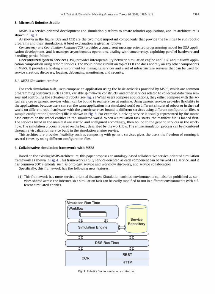
MSRS is a service-oriented development and simulation platform to create robotics applications, and its architecture isshown in Fig. 1.
As shown in the figure, DSS and CCR are the two most important components that provide the facilities to run roboticprograms and their simulations. A brief explanation is given as follows:
Concurrency and Coordination Runtime (CCR) provides a concurrent message-oriented programming model for SOA appli-cation development, and it manages asynchronous operations, dealing with concurrency, exploiting parallel hardware andhandling partial failure.
Decentralized System Services (DSS) provides interoperability between simulation engine and CCR, and it allows appli-cation composition using remote services. The DSS runtime is built on top of CCR and does not rely on any other componentsin MSRS. It provides a hosting environment for managing services and a set of infrastructure services that can be used forservice creation, discovery, logging, debugging, monitoring, and security.
3.1. MSRS Simulation runtime
For each simulation task, users compose an application using the basic activities provided by MSRS, which are commonprogramming constructs such as data, variable, if-then-else constructs, and other services related to collecting data from sen-sors and controlling the actuators of robots (see Fig. 2). When users compose applications, they either compose with the ac-tual services or generic services which can be bound to real services at runtime. Using generic services provides flexibility tothe applications, because users can run the same application in a simulated world on different simulated robots or in the realworld on different robot hardware, with the generic services bound to different services using different configuration files. Asample configuration (manifest) file is shown in Fig. 3. For example, a driving service is usually represented by the motorbase entities or the wheel entities in the simulated world. When a simulation task starts, the manifest file is loaded first.The services listed in the manifest are started and configured accordingly, then bound to the generic services in the work-flow. The simulation process is based on the logic described by the workflow. The entire simulation process can be monitoredthrough a visualization service built in the simulation engine service.
This architecture provides flexibility such as composing with generic services gives the users the freedom of running itseveral times by using different configuration files.
4. Collaborative simulation framework with MSRS
Based on the existing MSRS architecture, this paper proposes an ontology-based collaborative service-oriented simulationframework as shown in Fig. 4. This framework is fully service-oriented as each component can be viewed as a service, and ithas common SOC elements such as ontology, service and workflow discovery, and service collaboration.
Specifically, this framework has the following new features:
(1) This framework has more service-oriented features. Simulation entities, environments can also be published as ser-vices shared across the internet, so a simulation task can be easily modified to run in different environments with dif-ferent simulated entities.
Fig. 1. Robotics Studio simulation architecture.
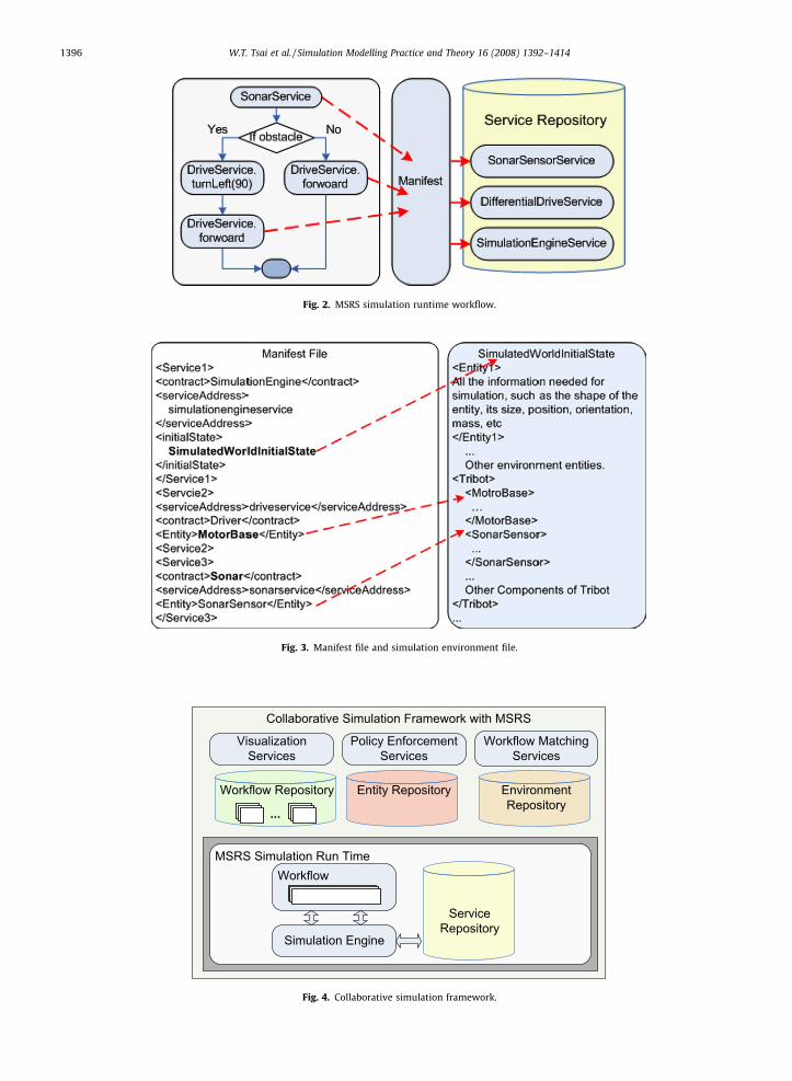
Fig. 2. MSRS simulation runtime workflow.
Fig. 3. Manifest file and simulation environment file.
Fig. 4. Collaborative simulation framework.
1396 W.T. Tsai et al. / Simulation Modelling Practice and Theory 16 (2008) 1392–1414
W.T. Tsai et al. / Simulation Modelling Practice and Theory 16 (2008) 1392–1414 1397
(2) This framework separates the simulation environment and simulation entities. With them separated, one does notneed to create a new configuration file and a new initial state of the simulated world when running the simulationin a different environment with the same simulation entities. Moreover, new environments can be easily composedusing simulation entities.
(3) The framework has a set of ontology systems that facilitate service matching and discovering for application develop-ment. Several domain-specific ontology systems were added to classify function services, workflow templates, simu-lation entities, simulation environments. The reasoning abilities provided by the ontology systems can facilitate theservice matching process, and provide a certain level of flexibilities by returning the most compatible services whena perfect match cannot be found, and reduce the manual work for a user.
(4) This framework is divided into platform-dependent part and platform-independent part. Users can use platform-inde-pendent modeling languages to specify their workflows and map them into specific platforms to perform simulation.In this way, users will be able to share platform-independent parts with others while performing simulation on spe-cific platforms at the same time. This will be explained in detail in Section 4.2.
(5) The framework provides cross-referencing and traceability among all simulation assets such as services, workflows,simulation entities and simulation environments utilizing ontology systems, so it is relatively easy to adapt tochanges.
(6) This framework can be a collaborative framework. It can be empowered by the Web 2.0 principles [24], specifically‘‘users are treated as co-developers”. In other words, users are encouraged to publish their services, workflows, sim-ulation environments and entities, or improved the ones published by others. As more people publish their work, acritical mass can be created collaboratively.
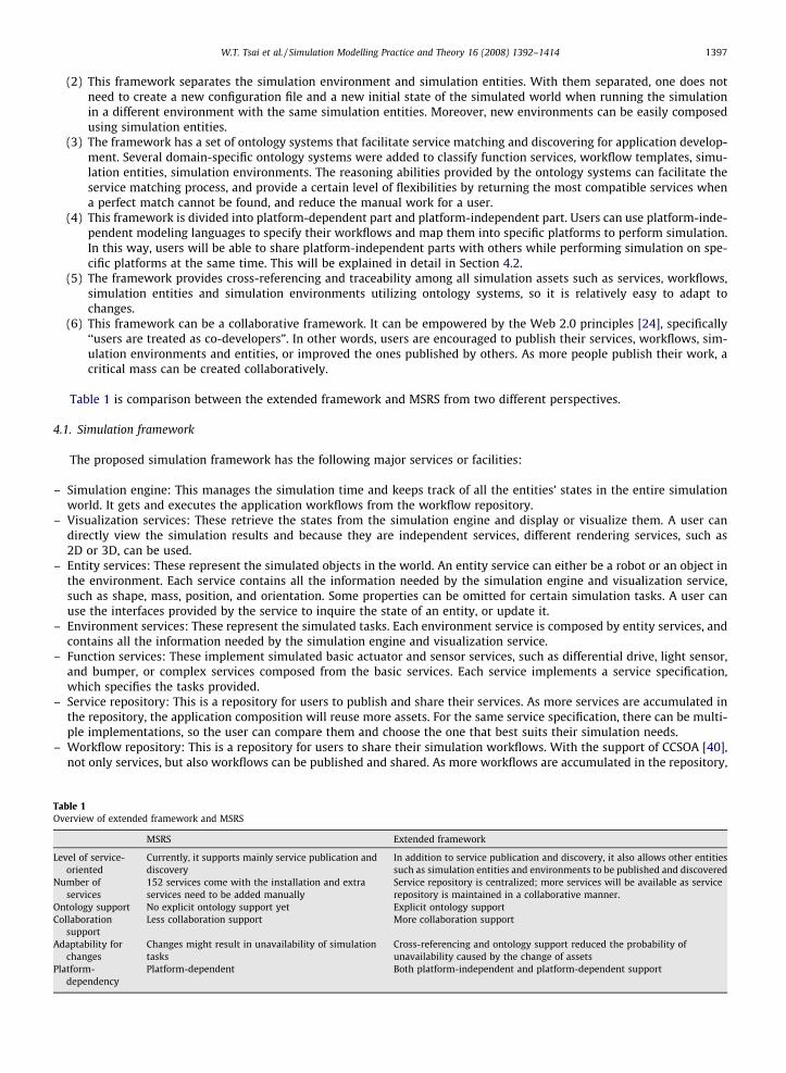
Table 1 is comparison between the extended framework and MSRS from two different perspectives.
4.1. Simulation framework
The proposed simulation framework has the following major services or facilities:
– Simulation engine: This manages the simulation time and keeps track of all the entities’ states in the entire simulationworld. It gets and executes the application workflows from the workflow repository.
– Visualization services: These retrieve the states from the simulation engine and display or visualize them. A user candirectly view the simulation results and because they are independent services, different rendering services, such as2D or 3D, can be used.
– Entity services: These represent the simulated objects in the world. An entity service can either be a robot or an object inthe environment. Each service contains all the information needed by the simulation engine and visualization service,such as shape, mass, position, and orientation. Some properties can be omitted for certain simulation tasks. A user canuse the interfaces provided by the service to inquire the state of an entity, or update it.
– Environment services: These represent the simulated tasks. Each environment service is composed by entity services, andcontains all the information needed by the simulation engine and visualization service.
– Function services: These implement simulated basic actuator and sensor services, such as differential drive, light sensor,and bumper, or complex services composed from the basic services. Each service implements a service specification,which specifies the tasks provided.
– Service repository: This is a repository for users to publish and share their services. As more services are accumulated inthe repository, the application composition will reuse more assets. For the same service specification, there can be multi-ple implementations, so the user can compare them and choose the one that best suits their simulation needs.
– Workflow repository: This is a repository for users to share their simulation workflows. With the support of CCSOA [40],not only services, but also workflows can be published and shared. As more workflows are accumulated in the repository,
Table 1Overview of extended framework and MSRS
MSRS Extended framework
Level of service-oriented
Currently, it supports mainly service publication anddiscovery
In addition to service publication and discovery, it also allows other entitiessuch as simulation entities and environments to be published and discovered
Number ofservices
152 services come with the installation and extraservices need to be added manually
Service repository is centralized; more services will be available as servicerepository is maintained in a collaborative manner.
Ontology support No explicit ontology support yet Explicit ontology supportCollaboration
supportLess collaboration support More collaboration support
Adaptability forchanges
Changes might result in unavailability of simulationtasks
Cross-referencing and ontology support reduced the probability ofunavailability caused by the change of assets
Platform-dependency
Platform-dependent Both platform-independent and platform-dependent support
1398 W.T. Tsai et al. / Simulation Modelling Practice and Theory 16 (2008) 1392–1414
users do not have to compose application from scratch. One can first search the workflow repository, find a workflow thatthey are interested in and start in from there. If no matching workflow is found, one can compose his own and publish it inthe repository for future use.
– Entity repository: This is a repository for users to publish and share simulated entities. Suppose a user did not find a sim-ulated environment needed in the environment repository, the person does not need to start from scratch. The user cansearch in the entity repository, and use the existing entities to compose the simulated world. In addition, one can also bindthe services used in a workflow with the simulated objects (mostly robots for robotic simulation) found in the repository.
– Environment repository: This is a repository for users to publish and share simulated environments and use them to com-pose new simulation tasks.
4.2. Collaborative simulation
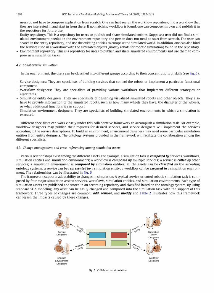
In the environment, the users can be classified into different groups according to their concentrations or skills (see Fig. 5):
– Service designers: They are specialists of building services that control the robots or implement a particular functionalcomponent.
– Workflow designers: They are specialists of providing various workflows that implement different strategies oralgorithms.
– Simulation entity designers: They are specialists of designing visualized simulated robots and other objects. They alsohave to provide information of the simulated robots, such as how many wheels they have, the diameter of the wheels,or what additional functions it can support.
– Simulation environment designers: They are specialists of building simulated environments in which a simulation isexecuted.
Different specialists can work closely under this collaborative framework to accomplish a simulation task. For example,workflow designers may publish their requests for desired services, and service designers will implement the servicesaccording to the service descriptions. To build an environment, environment designers may need some particular simulationentities from entity designers. The ontology systems provided in the framework will facilitate the collaboration among thedifferent specialists.
4.3. Change management and cross-referencing among simulation assets
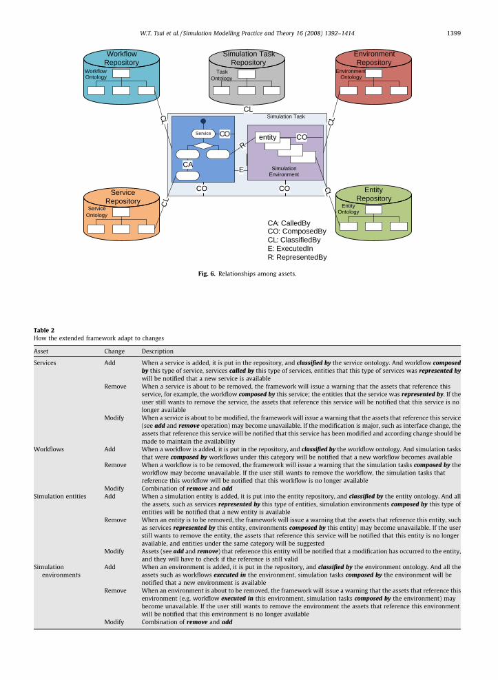
Various relationships exist among the different assets. For example, a simulation task is composed by services, workflows,simulation entities and simulation environments; a workflow is composed by multiple services; a service is called by otherservices; a simulation environment is composed by simulation entities; all the assets can be classified by the accordingontology systems; a service can be represented by a simulation entity; a workflow can be executed in a simulation environ-ment. The relationships can be illustrated in Fig. 6.
The framework supports adaptability to changes in simulation. A typical service-oriented robotic simulation task is com-posed by four major simulation assets: services, workflows, simulation entities, and simulation environments. Each type ofsimulation assets are published and stored in an according repository and classified based on the ontology system. By usingstandard SOA modeling, any asset can be easily changed and composed into the simulation task with the support of thisframework. Three types of changes are common: add, remove, and modify and Table 2 illustrates how this frameworkcan lessen the impacts caused by these changes.
Service Designers
Simulatin Environment
Designers
Simulation Entity
Designers
Workflow Designers
ProvideVer ify
Provide
Verify
Provide
Verify
ProvideVerify
Fig. 5. Collaborative simulation.
Service
Service Repository
Workflow Repository
EntityRepository
Environment Repository
entity
Simulation Environment
CL
CL
CL
CL
R
E
WorkflowOntology
Simulation Task
ServiceOntology
EntityOntology
EnvironmentOntology
CA: CalledByCO: ComposedByCL: ClassifiedByE: ExecutedInR: RepresentedBy
COCO
CA
COCO
Simulation TaskRepository
CL
TaskOntology
Fig. 6. Relationships among assets.
Table 2How the extended framework adapt to changes
Asset Change Description
Services Add When a service is added, it is put in the repository, and classified by the service ontology. And workflow composedby this type of service, services called by this type of services, entities that this type of services was represented bywill be notified that a new service is available
Remove When a service is about to be removed, the framework will issue a warning that the assets that reference thisservice, for example, the workflow composed by this service; the entities that the service was represented by. If theuser still wants to remove the service, the assets that reference this service will be notified that this service is nolonger available
Modify When a service is about to be modified, the framework will issue a warning that the assets that reference this service(see add and remove operation) may become unavailable. If the modification is major, such as interface change, theassets that reference this service will be notified that this service has been modified and according change should bemade to maintain the availability
Workflows Add When a workflow is added, it is put in the repository, and classified by the workflow ontology. And simulation tasksthat were composed by workflows under this category will be notified that a new workflow becomes available
Remove When a workflow is to be removed, the framework will issue a warning that the simulation tasks composed by theworkflow may become unavailable. If the user still wants to remove the workflow, the simulation tasks thatreference this workflow will be notified that this workflow is no longer available
Modify Combination of remove and addSimulation entities Add When a simulation entity is added, it is put into the entity repository, and classified by the entity ontology. And all
the assets, such as services represented by this type of entities, simulation environments composed by this type ofentities will be notified that a new entity is available
Remove When an entity is to be removed, the framework will issue a warning that the assets that reference this entity, suchas services represented by this entity, environments composed by this entity) may become unavailable. If the userstill wants to remove the entity, the assets that reference this service will be notified that this entity is no longeravailable, and entities under the same category will be suggested
Modify Assets (see add and remove) that reference this entity will be notified that a modification has occurred to the entity,and they will have to check if the reference is still valid
Simulationenvironments
Add When an environment is added, it is put in the repository, and classified by the environment ontology. And all theassets such as workflows executed in the environment, simulation tasks composed by the environment will benotified that a new environment is available
Remove When an environment is about to be removed, the framework will issue a warning that the assets that reference thisenvironment (e.g. workflow executed in this environment, simulation tasks composed by the environment) maybecome unavailable. If the user still wants to remove the environment the assets that reference this environmentwill be notified that this environment is no longer available
Modify Combination of remove and add
W.T. Tsai et al. / Simulation Modelling Practice and Theory 16 (2008) 1392–1414 1399
1400 W.T. Tsai et al. / Simulation Modelling Practice and Theory 16 (2008) 1392–1414
The framework will keep tracking what other assets a specific simulation asset is referenced by. Therefore, when a changeis made to an asset, the referencing assets will be notified to make changes accordingly.
4.4. Platform-independent simulation
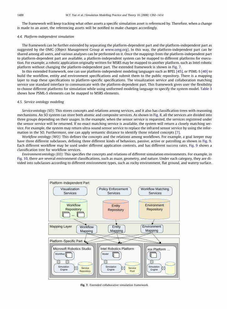
The framework can be further extended by separating the platform-dependent part and the platform-independent part assuggested by the OMG (Object Management Group at www.omg.org). In this way, the platform-independent part can beshared among all users, and various analyses can be performed on it. Once the mappings from the platform-independent partto platform-dependent part are available, a platform-independent system can be mapped to different platforms for execu-tion. For example, a robotic application originally written for MSRS may be mapped to another platform, such as Intel roboticplatform without changing the platform-independent part. The extended framework is shown in Fig. 7.
In this extended framework, one can use platform-independent modeling languages such as BPEL [45], or PSML-S [40] tobuild the workflow, entity and environment specifications and submit them to the public repository. There is a mappinglayer to map these specifications to platform-specific specifications. The visualization service and collaboration matchingservice use standard interface to communicate with the platform-dependent part. This framework gives user the flexibilityto choose different platforms for simulation while using uniformed modeling language to specify the system model. Table 3shows how PSML-S elements can be mapped to MSRS elements.
4.5. Service ontology modeling
Serviceontology (SO): This stores concepts and relations among services, and it also has classification trees with reasoningmechanisms. An SO system can store both atomic and composite services. As shown in Fig. 8, all the services are divided intothree groups depending on their usages. In the example, when the sensor service is requested, the services registered underthe sensor service will be returned. If no exact matching service is available, the system will return a closely matching ser-vice. For example, the system may return ultra-sound sensor service to replace the infrared sensor service by using the infor-mation in the SO. Furthermore, one can apply semantic distance to identify those related concepts [7].
Workflow ontology (WO): This defines the concepts and the relations among workflows. For example, a goal keeper mayhave three different subclasses, defining three different kinds of behaviors, passive, active or patrolling as shown in Fig. 9.Each different workflow may be used under different application contexts, and has different success rates. Fig. 9 shows aclassification tree for workflow services.
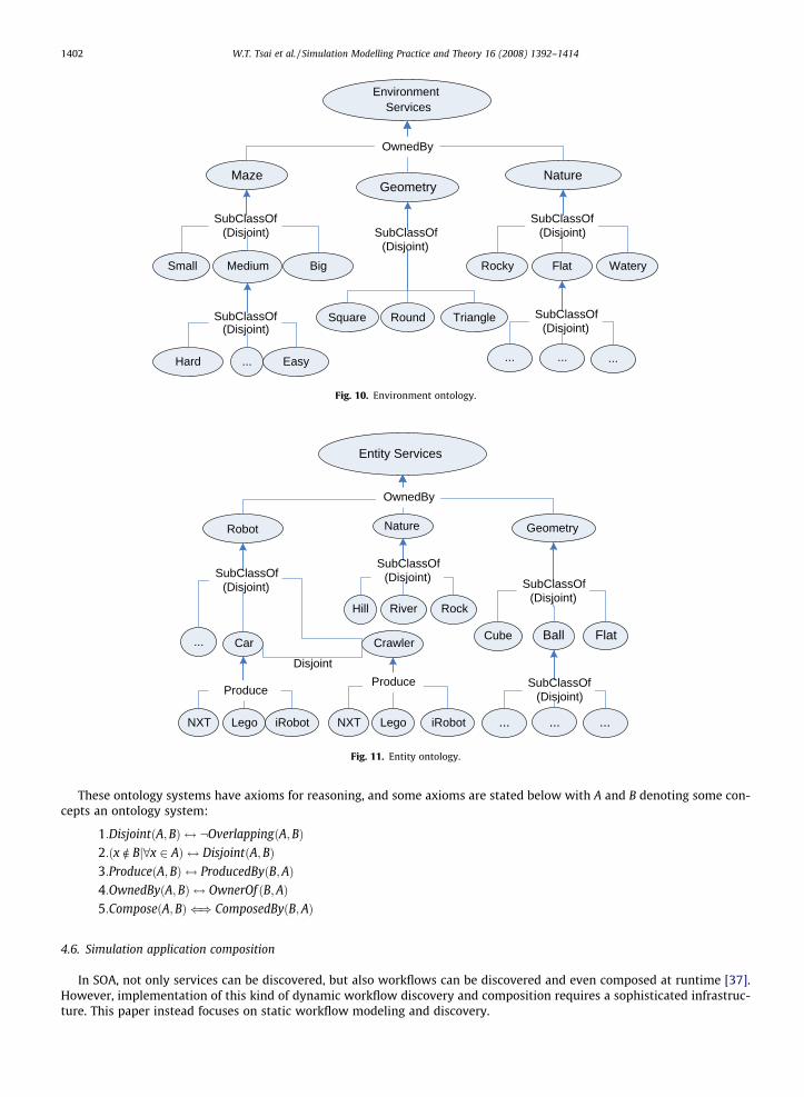
Environmentontology (EO): This specifies the concepts and relations of different simulation environments. For example, inFig. 10, there are several environment classifications, such as maze, geometry, and nature. Under each category, they are di-vided into subclasses according to different environment types, such as rocky environment, flat ground, and watery surface.
Platform-Specific Part
Platform-Independent Part
Visualization Services
Policy Enforcement Services
Microsoft Robotics Studio
Simulation Engine
Workflow
Service Repository
Workflow Matching Services
Mapping Layer Workflow Mapping
Entity Mapping
Environment Mapping
Workflow Repository
...
Environment Repository
Entity Repository
xxx Platform ...
Simulation Engine
Intel Robotics Platform
Simulation Engine
Model
Service Pool
Fig. 7. Extended collaborative simulation framework.
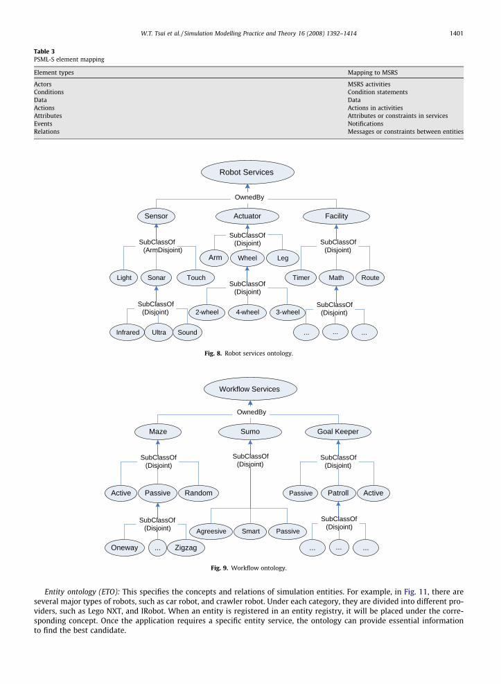
Table 3PSML-S element mapping
Element types Mapping to MSRS
Actors MSRS activitiesConditions Condition statementsData DataActions Actions in activitiesAttributes Attributes or constraints in servicesEvents NotificationsRelations Messages or constraints between entities
Robot Services
Sensor Actuator Facility
Wheel Leg
Light Sonar Touch
Infrared Ultra Sound
2-wheel 4-wheel 3-wheel
Timer Math Route
... ......
OwnedBy
SubClassOf(ArmDisjoint)
SubClassOf(Disjoint)
SubClassOf(Disjoint)
SubClassOf(Disjoint)
SubClassOf(Disjoint)
SubClassOf(Disjoint)
Arm
Fig. 8. Robot services ontology.
Workflow Services
Maze Sumo Goal Keeper
Agreesive Passive
Active Passive
Oneway ... Zigzag
Patroll Active
... ......
Smart
OwnedBy
SubClassOf(Disjoint)
SubClassOf(Disjoint)
SubClassOf(Disjoint)
Random Passive
SubClassOf(Disjoint)
SubClassOf(Disjoint)
Fig. 9. Workflow ontology.
W.T. Tsai et al. / Simulation Modelling Practice and Theory 16 (2008) 1392–1414 1401
Entity ontology (ETO): This specifies the concepts and relations of simulation entities. For example, in Fig. 11, there areseveral major types of robots, such as car robot, and crawler robot. Under each category, they are divided into different pro-viders, such as Lego NXT, and IRobot. When an entity is registered in an entity registry, it will be placed under the corre-sponding concept. Once the application requires a specific entity service, the ontology can provide essential informationto find the best candidate.
Environment Services
MazeGeometry
Nature
Square Triangle
Small Medium Big
Hard ... Easy
Rocky Flat Watery
... ......
Round
OwnedBy
SubClassOf(Disjoint)
SubClassOf(Disjoint)
SubClassOf(Disjoint)
SubClassOf(Disjoint)
SubClassOf(Disjoint)
Fig. 10. Environment ontology.
Entity Services
Robot Nature Geometry
Hill Rock
... Car Crawler
NXT Lego iRobot
Cube Ball Flat
... ......
River
NXT Lego iRobot
Disjoint
OwnedBy
SubClassOf(Disjoint)
ProduceProduce
SubClassOf(Disjoint) SubClassOf
(Disjoint)
SubClassOf(Disjoint)
Fig. 11. Entity ontology.
1402 W.T. Tsai et al. / Simulation Modelling Practice and Theory 16 (2008) 1392–1414
These ontology systems have axioms for reasoning, and some axioms are stated below with A and B denoting some con-cepts an ontology system:
1:DisjointðA;BÞ $ :OverlappingðA;BÞ2:ðx R Bj8x 2 AÞ $ DisjointðA;BÞ3:ProduceðA;BÞ $ ProducedByðB;AÞ4:OwnedByðA;BÞ $ OwnerOf ðB;AÞ5:ComposeðA;BÞ () ComposedByðB;AÞ
4.6. Simulation application composition
In SOA, not only services can be discovered, but also workflows can be discovered and even composed at runtime [37].However, implementation of this kind of dynamic workflow discovery and composition requires a sophisticated infrastruc-ture. This paper instead focuses on static workflow modeling and discovery.
W.T. Tsai et al. / Simulation Modelling Practice and Theory 16 (2008) 1392–1414 1403
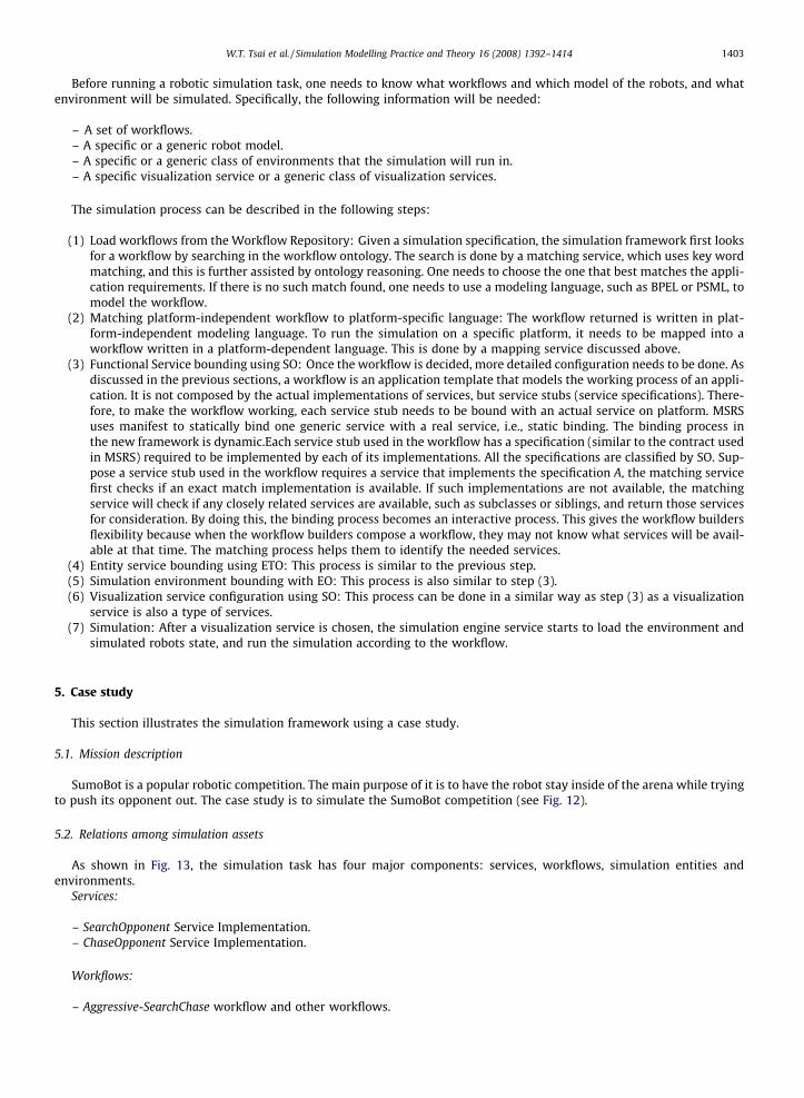
Before running a robotic simulation task, one needs to know what workflows and which model of the robots, and whatenvironment will be simulated. Specifically, the following information will be needed:
– A set of workflows.– A specific or a generic robot model.– A specific or a generic class of environments that the simulation will run in.– A specific visualization service or a generic class of visualization services.
The simulation process can be described in the following steps:
(1) Load workflows from the Workflow Repository: Given a simulation specification, the simulation framework first looksfor a workflow by searching in the workflow ontology. The search is done by a matching service, which uses key wordmatching, and this is further assisted by ontology reasoning. One needs to choose the one that best matches the appli-cation requirements. If there is no such match found, one needs to use a modeling language, such as BPEL or PSML, tomodel the workflow.
(2) Matching platform-independent workflow to platform-specific language: The workflow returned is written in plat-form-independent modeling language. To run the simulation on a specific platform, it needs to be mapped into aworkflow written in a platform-dependent language. This is done by a mapping service discussed above.
(3) Functional Service bounding using SO: Once the workflow is decided, more detailed configuration needs to be done. Asdiscussed in the previous sections, a workflow is an application template that models the working process of an appli-cation. It is not composed by the actual implementations of services, but service stubs (service specifications). There-fore, to make the workflow working, each service stub needs to be bound with an actual service on platform. MSRSuses manifest to statically bind one generic service with a real service, i.e., static binding. The binding process inthe new framework is dynamic.Each service stub used in the workflow has a specification (similar to the contract usedin MSRS) required to be implemented by each of its implementations. All the specifications are classified by SO. Sup-pose a service stub used in the workflow requires a service that implements the specification A, the matching servicefirst checks if an exact match implementation is available. If such implementations are not available, the matchingservice will check if any closely related services are available, such as subclasses or siblings, and return those servicesfor consideration. By doing this, the binding process becomes an interactive process. This gives the workflow buildersflexibility because when the workflow builders compose a workflow, they may not know what services will be avail-able at that time. The matching process helps them to identify the needed services.
(4) Entity service bounding using ETO: This process is similar to the previous step.(5) Simulation environment bounding with EO: This process is also similar to step (3).(6) Visualization service configuration using SO: This process can be done in a similar way as step (3) as a visualization
service is also a type of services.(7) Simulation: After a visualization service is chosen, the simulation engine service starts to load the environment and
simulated robots state, and run the simulation according to the workflow.
5. Case study
This section illustrates the simulation framework using a case study.
5.1. Mission description
SumoBot is a popular robotic competition. The main purpose of it is to have the robot stay inside of the arena while tryingto push its opponent out. The case study is to simulate the SumoBot competition (see Fig. 12).
5.2. Relations among simulation assets
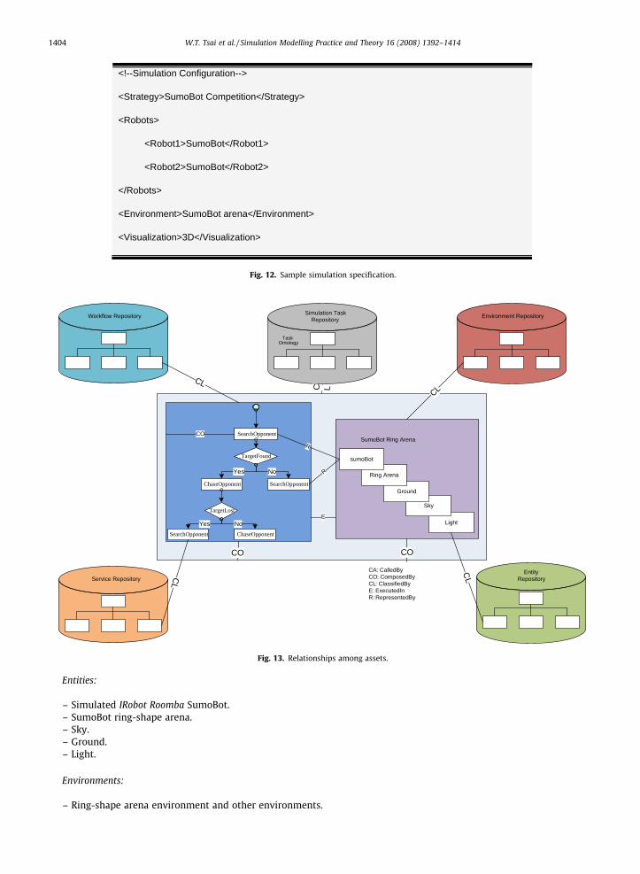
As shown in Fig. 13, the simulation task has four major components: services, workflows, simulation entities andenvironments.
Services:
– SearchOpponent Service Implementation.– ChaseOpponent Service Implementation.
Workflows:
– Aggressive-SearchChase workflow and other workflows.
<!--Simulation Configuration-->
<Strategy>SumoBot Competition</Strategy>
<Robots>
<Robot1>SumoBot</Robot1>
<Robot2>SumoBot</Robot2>
</Robots>
<Environment>SumoBot arena</Environment>
<Visualization>3D</Visualization>
Fig. 12. Sample simulation specification.
CA: CalledByCO: ComposedByCL: ClassifiedByE: ExecutedInR: RepresentedBy
ChaseOpponent
TargetFound
SearchOpponent
Yes No
TargetLost
SearchOpponent ChaseOpponent
Yes No
SearchOpponentSumoBot Ring Arena
Light
Sky
Ground
Ring Arena
sumoBot
R
R
CO
E
Workflow Repository
Service Repository
Environment Repository
EntityRepository
Simulation TaskRepository
TaskOntology
CO CO
CL
CL
CL
CLC L
Fig. 13. Relationships among assets.
1404 W.T. Tsai et al. / Simulation Modelling Practice and Theory 16 (2008) 1392–1414
Entities:
– Simulated IRobot Roomba SumoBot.– SumoBot ring-shape arena.– Sky.– Ground.– Light.
Environments:
– Ring-shape arena environment and other environments.
W.T. Tsai et al. / Simulation Modelling Practice and Theory 16 (2008) 1392–1414 1405
Relations among the simulation assets:In this sample, the workflow is composed by two service implementations of SearchOpponent, ChaseOpponent. The sim-
ulation environment is composed by Simulated IRobot Roomba SumoBot, SumoBot ring-shape arena, sky, ground, and light.The workflow is executed in the simulation environment. The two services are represented by simulated IRobot RoombaSumoBot. The workflow is classified by the workflow ontology under the Workflow-Sumo-Aggressive-SearchChase category;the environment is classified by the environment ontology under the Environment-Sumo-Ring-Small category. Service imple-mentation of SearchOpponent is classified by the service ontology under Service-Complex Service-Sumo-SearchOpponent cat-egory; Service implementation of ChaseOpponent is classified by the service ontology under Service-Complex Service-Sumo-ChaseOpponent. The simulated IRobot Roomba SumoBot is classified by the entity ontology under Entity-Robot-Sumo-IRobot;the ring-shape SumoBot arena is classified by the entity ontology under Entity-Geometry-Sumo-Arena-Ring; Sky, ground andlight are classified by the entity ontology under Entity-Nature. These relationships are useful in assessing the impacts ofchanges.
5.3. Application modeling
This simulation uses four repositories to store the four ontology systems as presented in Section 4.1 including WorkflowRepository, Service Repository, Entity Repository and Environment Repository.
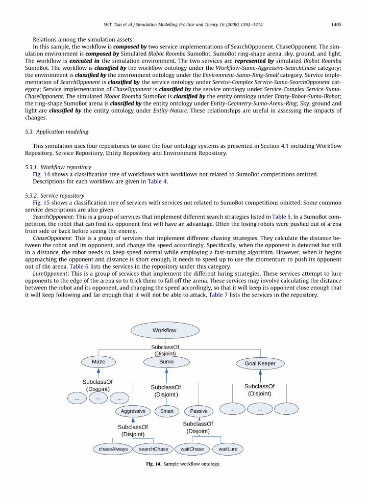
5.3.1. Workflow repositoryFig. 14 shows a classification tree of workflows with workflows not related to SumoBot competitions omitted.Descriptions for each workflow are given in Table 4.
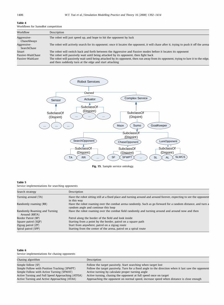
5.3.2. Service repositoryFig. 15 shows a classification tree of services with services not related to SumoBot competitions omitted. Some common
service descriptions are also given.SearchOpponent: This is a group of services that implement different search strategies listed in Table 5. In a SumoBot com-
petition, the robot that can find its opponent first will have an advantage. Often the losing robots were pushed out of arenafrom side or back before seeing the enemy.
ChaseOpponent: This is a group of services that implement different chasing strategies. They calculate the distance be-tween the robot and its opponent, and change the speed accordingly. Specifically, when the opponent is detected but stillin a distance, the robot needs to keep speed normal while employing a fast-turning algorithm. However, when it beginsapproaching the opponent and distance is short enough, it needs to speed up to use the momentum to push its opponentout of the arena. Table 6 lists the services in the repository under this category.
LureOpponent: This is a group of services that implement the different luring strategies. These services attempt to lureopponents to the edge of the arena so to trick them to fall off the arena. These services may involve calculating the distancebetween the robot and its opponent, and changing the speed accordingly, so that it will keep its opponent close enough thatit will keep following and far enough that it will not be able to attack. Table 7 lists the services in the repository.
SubclassOf(Disjoint )
SubclassOf(Disjoint)
Workflow
Maze Sumo Goal Keeper
Aggressive Passive
SubclassOf(Disjoint)
... ... ...Smart
SubclassOf(Disjoint)
... ......
chaseAlways searchChase
SubclassOf(Disjoint)
waitChase waitLure
SubclassOf(Disjoint)
Fig. 14. Sample workflow ontology.
SubclassOf(Disjoint)
Owned
Robot Services
Sensor Actuator Complex Service
... ...SubclassOf
(Disjoint)
Maze Sumo GoalKeeper
...SubclassOf
(Disjoint)
... ......
SubclassOf(Disjoint)
SearchOpponent LureOpponentChaseOpponent
SubclassOf(Disjoint)
TA ...RR
SubclassOf(Disjoint)
SF ...SFWPT
SubclassOf(Disjoint)
SL SLWCSAL
Fig. 15. Sample service ontology.
Table 5Service implementations for searching opponents
Search strategy Description
Turning around (TA) Have the robot sitting still at a fixed place and turning around and around forever, expecting to see the opponentin this way
Randomly roaming (RR) Have the robot roaming over the combat arena randomly. Such as go forward for a random distance, and turn arandom angle and continue this loop
Randomly Roaming and TurningAround (RRTA)
Have the robot roaming over the combat field randomly and turning around and around now and then
Border Patrol (BP) Patrol along the border of the field and look insideSquare patrol (SQP) Starting from a point by the border, patrol on a square pathZigzag patrol (ZP) Start from anywhere, patrol on a zigzag routeSpiral patrol (SPP) Starting from the center of the arena, patrol on a spiral route
Table 4Workflows for SumoBot competition
Workflow Description
Aggressive-ChaseAlways
The robot will just speed up, and hope to hit the opponent by luck
Aggressive-SearchChase
The robot will actively search for its opponent; once it locates the opponent, it will chase after it, trying to push it off the arena
Smart The robot will switch back and forth between the Aggressive and Passive modes before it locates its opponentPassive-WaitChase The robot will passively wait until being attacked by its opponent, then fight backPassive-WaitLure The robot will passively wait until being attacked by its opponent, then run away from its opponent, trying to lure it to the edge,
and then suddenly turn at the edge and start attacking
Table 6Service implementations for chasing opponents
Chasing algorithm Description
Simple follow (SF) Follow the target passively. Start searching when target lostSimple Follow with Position Tracking (SFWPT) Follow the target passively. Turn for a fixed angle to the direction when it last saw the opponentSimple Follow with Active Turning (SFWAT) Active turning by calculate proper turning angleActive Turning and Full Speed Approaching (ATFSA) Active turning, chasing the opponent at full speed once on targetActive Turning and Active Approaching (ATAA) Approaching the opponent on normal speed, increase speed when distance is close enough
1406 W.T. Tsai et al. / Simulation Modelling Practice and Theory 16 (2008) 1392–1414
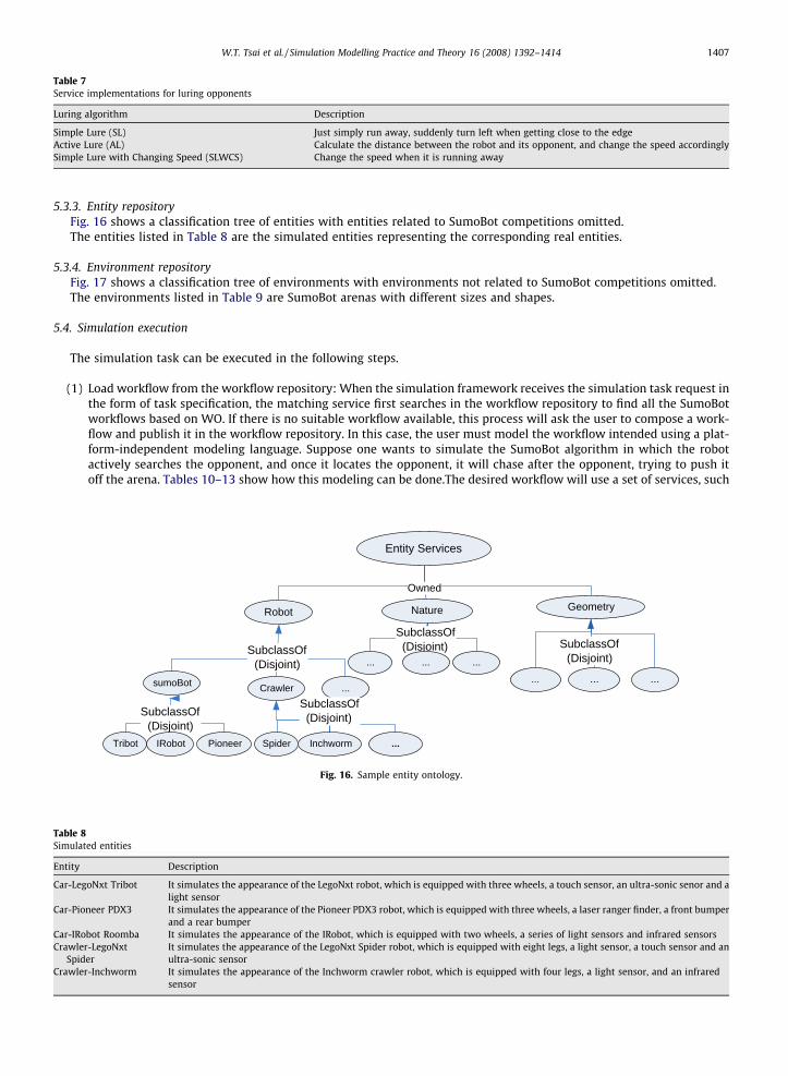
Table 7Service implementations for luring opponents
Luring algorithm Description
Simple Lure (SL) Just simply run away, suddenly turn left when getting close to the edgeActive Lure (AL) Calculate the distance between the robot and its opponent, and change the speed accordinglySimple Lure with Changing Speed (SLWCS) Change the speed when it is running away
W.T. Tsai et al. / Simulation Modelling Practice and Theory 16 (2008) 1392–1414 1407
5.3.3. Entity repositoryFig. 16 shows a classification tree of entities with entities related to SumoBot competitions omitted.The entities listed in Table 8 are the simulated entities representing the corresponding real entities.
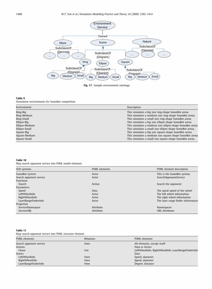
5.3.4. Environment repositoryFig. 17 shows a classification tree of environments with environments not related to SumoBot competitions omitted.The environments listed in Table 9 are SumoBot arenas with different sizes and shapes.
5.4. Simulation execution
The simulation task can be executed in the following steps.
(1) Load workflow from the workflow repository: When the simulation framework receives the simulation task request inthe form of task specification, the matching service first searches in the workflow repository to find all the SumoBotworkflows based on WO. If there is no suitable workflow available, this process will ask the user to compose a work-flow and publish it in the workflow repository. In this case, the user must model the workflow intended using a plat-form-independent modeling language. Suppose one wants to simulate the SumoBot algorithm in which the robotactively searches the opponent, and once it locates the opponent, it will chase after the opponent, trying to push itoff the arena. Tables 10–13 show how this modeling can be done.The desired workflow will use a set of services, such
Table 8Simulated entities
Entity Description
Car-LegoNxt Tribot It simulates the appearance of the LegoNxt robot, which is equipped with three wheels, a touch sensor, an ultra-sonic senor and alight sensor
Car-Pioneer PDX3 It simulates the appearance of the Pioneer PDX3 robot, which is equipped with three wheels, a laser ranger finder, a front bumperand a rear bumper
Car-IRobot Roomba It simulates the appearance of the IRobot, which is equipped with two wheels, a series of light sensors and infrared sensorsCrawler-LegoNxt
SpiderIt simulates the appearance of the LegoNxt Spider robot, which is equipped with eight legs, a light sensor, a touch sensor and anultra-sonic sensor
Crawler-Inchworm It simulates the appearance of the Inchworm crawler robot, which is equipped with four legs, a light sensor, and an infraredsensor
SubclassOf(Disjoint)
Owned
Entity Services
Robot Nature Geometry
... ...
SubclassOf(Disjoint)
... ... ......
SubclassOf(Disjoint)
sumoBot ...Crawler
SubclassOf(Disjoint)
Tribot PioneerIRobot
SubclassOf(Disjoint)
Spider ...Inchworm
Fig. 16. Sample entity ontology.
SubclassOf(Disjoint)
Owned
Environment Service
Maze Sumo Nature
Ring Square
SubclassOf(Disjoint)
... ... ...
Ellipse
SubclassOf(Disjoint)
... ......
SubclassOf(Disjoint)
Big SmallMedium
SubclassOf(Disjoint)Big SmallMedium
SubclassOf(Disjoint)
Big SmallMedium
Fig. 17. Sample environment ontology.
Table 9Simulation environments for SumoBot competition
Environment Description
Ring-Big This simulates a big size ring-shape SumoBot arenaRing-Medium This simulates a medium size ring-shape SumoBot arenaRing-Small This simulates a small size ring-shape SumoBot arenaEllipse-Big This simulates a big size ellipse-shape SumoBot arenaEllipse-Medium This simulates a medium size ellipse-shape SumoBot arenaEllipse-Small This simulates a small size ellipse-shape SumoBot arenaSquare-Big This simulates a big size square-shape SumoBot arenaSquare-Medium This simulates a medium size square-shape SumoBot arenaSquare-Small This simulates a small size square-shape SumoBot arena
Table 10Map search opponent service into PSML model elements
SOA systems PSML elements PSML element description
SumoBot system Actor This is the SumoBot systemSearch opponent service Actor SearchOpponentServiceFunctions
Search Action Search the opponentParameters
Speed Data The spiral speed of the wheelLeftWheelInfo Actor The left wheel informationRightWheelInfo Actor The right wheel informationLaserRangeFinderInfo Actor The laser range finder information
PropertiesServiceNamespace Attribute NamespacesServiceURL Attribute URL Attributes
Table 11Map search opponent service into PSML structure element
PSML elements Relations PSML elements
Search opponent service Own All elements, except itselfActions Data or Actors
Chase Use LeftWheelInfo, RightWheelInfo, LaserRangeFinderInfoActors Data
LeftWheelInfo Own Speed, diameterRightWheelInfo Own Speed, diameterLaserRangeFinderInfo Own Degree, distance
1408 W.T. Tsai et al. / Simulation Modelling Practice and Theory 16 (2008) 1392–1414
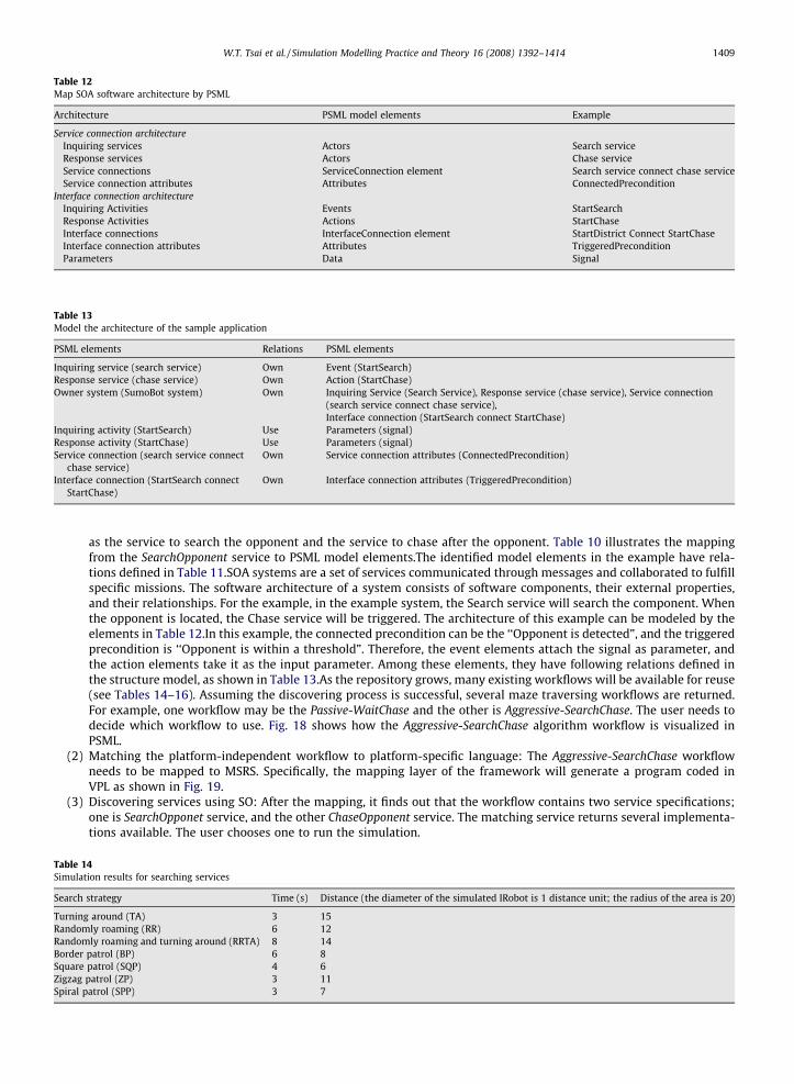
Table 12Map SOA software architecture by PSML
Architecture PSML model elements Example
Service connection architectureInquiring services Actors Search serviceResponse services Actors Chase serviceService connections ServiceConnection element Search service connect chase serviceService connection attributes Attributes ConnectedPrecondition
Interface connection architectureInquiring Activities Events StartSearchResponse Activities Actions StartChaseInterface connections InterfaceConnection element StartDistrict Connect StartChaseInterface connection attributes Attributes TriggeredPreconditionParameters Data Signal
Table 13Model the architecture of the sample application
PSML elements Relations PSML elements
Inquiring service (search service) Own Event (StartSearch)Response service (chase service) Own Action (StartChase)Owner system (SumoBot system) Own Inquiring Service (Search Service), Response service (chase service), Service connection
(search service connect chase service),Interface connection (StartSearch connect StartChase)
Inquiring activity (StartSearch) Use Parameters (signal)Response activity (StartChase) Use Parameters (signal)Service connection (search service connect
chase service)Own Service connection attributes (ConnectedPrecondition)
Interface connection (StartSearch connectStartChase)
Own Interface connection attributes (TriggeredPrecondition)
W.T. Tsai et al. / Simulation Modelling Practice and Theory 16 (2008) 1392–1414 1409
as the service to search the opponent and the service to chase after the opponent. Table 10 illustrates the mappingfrom the SearchOpponent service to PSML model elements.The identified model elements in the example have rela-tions defined in Table 11.SOA systems are a set of services communicated through messages and collaborated to fulfillspecific missions. The software architecture of a system consists of software components, their external properties,and their relationships. For the example, in the example system, the Search service will search the component. Whenthe opponent is located, the Chase service will be triggered. The architecture of this example can be modeled by theelements in Table 12.In this example, the connected precondition can be the ‘‘Opponent is detected”, and the triggeredprecondition is ‘‘Opponent is within a threshold”. Therefore, the event elements attach the signal as parameter, andthe action elements take it as the input parameter. Among these elements, they have following relations defined inthe structure model, as shown in Table 13.As the repository grows, many existing workflows will be available for reuse(see Tables 14–16). Assuming the discovering process is successful, several maze traversing workflows are returned.For example, one workflow may be the Passive-WaitChase and the other is Aggressive-SearchChase. The user needs todecide which workflow to use. Fig. 18 shows how the Aggressive-SearchChase algorithm workflow is visualized inPSML.
(2) Matching the platform-independent workflow to platform-specific language: The Aggressive-SearchChase workflowneeds to be mapped to MSRS. Specifically, the mapping layer of the framework will generate a program coded inVPL as shown in Fig. 19.
(3) Discovering services using SO: After the mapping, it finds out that the workflow contains two service specifications;one is SearchOpponet service, and the other ChaseOpponent service. The matching service returns several implementa-tions available. The user chooses one to run the simulation.
Table 14Simulation results for searching services
Search strategy Time (s) Distance (the diameter of the simulated IRobot is 1 distance unit; the radius of the area is 20)
Turning around (TA) 3 15Randomly roaming (RR) 6 12Randomly roaming and turning around (RRTA) 8 14Border patrol (BP) 6 8Square patrol (SQP) 4 6Zigzag patrol (ZP) 3 11Spiral patrol (SPP) 3 7
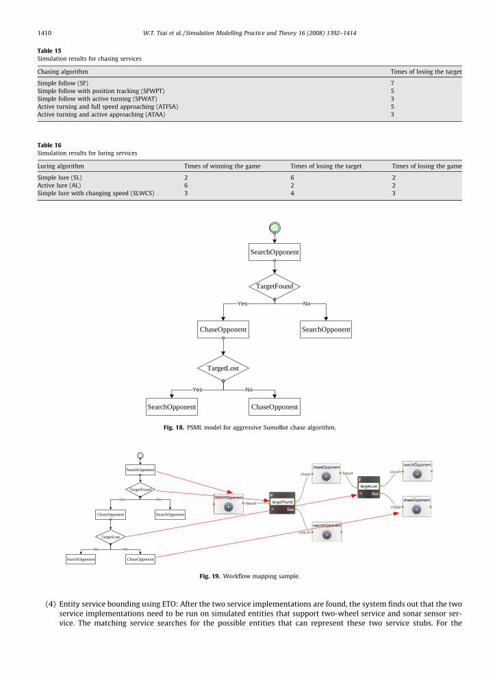
Table 15Simulation results for chasing services
Chasing algorithm Times of losing the target
Simple follow (SF) 7Simple follow with position tracking (SFWPT) 5Simple follow with active turning (SFWAT) 3Active turning and full speed approaching (ATFSA) 5Active turning and active approaching (ATAA) 3
Table 16Simulation results for luring services
Luring algorithm Times of winning the game Times of losing the target Times of losing the game
Simple lure (SL) 2 6 2Active lure (AL) 6 2 2Simple lure with changing speed (SLWCS) 3 4 3
ChaseOpponent
TargetFound
SearchOpponent
Yes No
TargetLost
SearchOpponent ChaseOpponent
Yes No
SearchOpponent
Fig. 18. PSML model for aggressive SumoBot chase algorithm.
ChaseOpponent
TargetFound
SearchOpponent
TargetLost
SearchOpponent ChaseOpponent
SearchOpponent
Fig. 19. Workflow mapping sample.
1410 W.T. Tsai et al. / Simulation Modelling Practice and Theory 16 (2008) 1392–1414
(4) Entity service bounding using ETO: After the two service implementations are found, the system finds out that the twoservice implementations need to be run on simulated entities that support two-wheel service and sonar sensor ser-vice. The matching service searches for the possible entities that can represent these two service stubs. For the
W.T. Tsai et al. / Simulation Modelling Practice and Theory 16 (2008) 1392–1414 1411
two-wheel drive service stub, the results returned are {LegoNxt Tribot, IRobot Roomba,Pioneer PDX3}; for the sonarsensor service stub, the results returned are {IRobot Roomba,Pioneer PDX3}. The intersection of the two sets is {IRobotRoomba,Pioneer PDX3} and both robots in the intersection are of ‘‘SumoBot” type entities, so they are used. The userwill be prompted to choose one. Assuming the user chooses IRobot, the two services are then configured according tothe IRobot Roomba, such the wheels’ size, and the distance between the two wheels, and the measurement limit of thesonar.Because a SumoBot competition involves two simulated robots, process 1–4 will be executed again for the sec-ond robot.
(5) Select an environment using EO: After the two services are fully configured, the matching service searches the envi-ronments that meet the user’s requirement, e.g., a small arena, in the environment repository. Several small arenaswith different shapes are returned. The users will be prompted to choose one from them. Assuming the user choosesthe ring-shape arena.
(6) Visualization service configuration: Similarly, a 3D visualization service can be chosen.(7) Simulation execution: After all the configurations have been set up, the simulation engine service loads the SumoBot
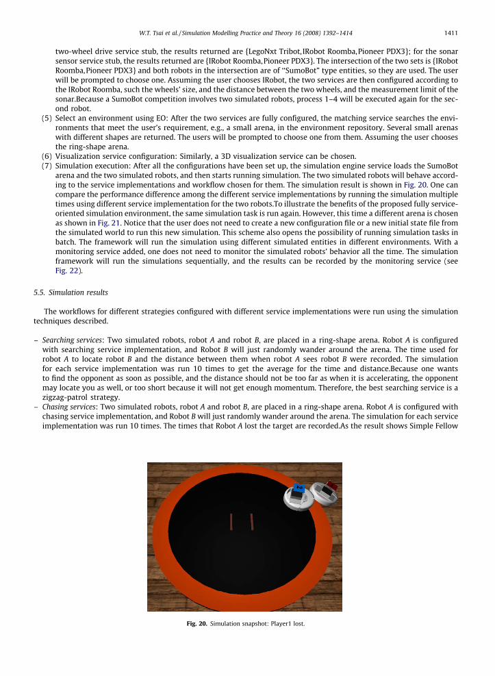
arena and the two simulated robots, and then starts running simulation. The two simulated robots will behave accord-ing to the service implementations and workflow chosen for them. The simulation result is shown in Fig. 20. One cancompare the performance difference among the different service implementations by running the simulation multipletimes using different service implementation for the two robots.To illustrate the benefits of the proposed fully service-oriented simulation environment, the same simulation task is run again. However, this time a different arena is chosenas shown in Fig. 21. Notice that the user does not need to create a new configuration file or a new initial state file fromthe simulated world to run this new simulation. This scheme also opens the possibility of running simulation tasks inbatch. The framework will run the simulation using different simulated entities in different environments. With amonitoring service added, one does not need to monitor the simulated robots’ behavior all the time. The simulationframework will run the simulations sequentially, and the results can be recorded by the monitoring service (seeFig. 22).
5.5. Simulation results
The workflows for different strategies configured with different service implementations were run using the simulationtechniques described.
– Searching services: Two simulated robots, robot A and robot B, are placed in a ring-shape arena. Robot A is configuredwith searching service implementation, and Robot B will just randomly wander around the arena. The time used forrobot A to locate robot B and the distance between them when robot A sees robot B were recorded. The simulationfor each service implementation was run 10 times to get the average for the time and distance.Because one wantsto find the opponent as soon as possible, and the distance should not be too far as when it is accelerating, the opponentmay locate you as well, or too short because it will not get enough momentum. Therefore, the best searching service is azigzag-patrol strategy.
– Chasing services: Two simulated robots, robot A and robot B, are placed in a ring-shape arena. Robot A is configured withchasing service implementation, and Robot B will just randomly wander around the arena. The simulation for each serviceimplementation was run 10 times. The times that Robot A lost the target are recorded.As the result shows Simple Fellow
Fig. 20. Simulation snapshot: Player1 lost.
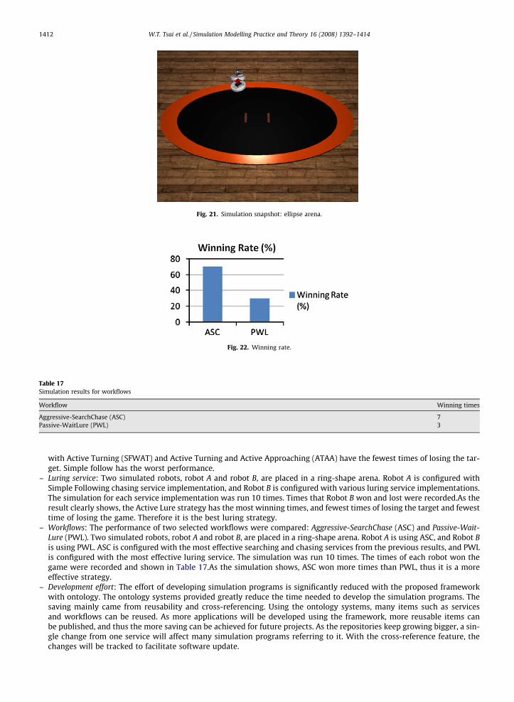
Fig. 21. Simulation snapshot: ellipse arena.
Fig. 22. Winning rate.
Table 17Simulation results for workflows
Workflow Winning times
Aggressive-SearchChase (ASC) 7Passive-WaitLure (PWL) 3
1412 W.T. Tsai et al. / Simulation Modelling Practice and Theory 16 (2008) 1392–1414
with Active Turning (SFWAT) and Active Turning and Active Approaching (ATAA) have the fewest times of losing the tar-get. Simple follow has the worst performance.
– Luring service: Two simulated robots, robot A and robot B, are placed in a ring-shape arena. Robot A is configured withSimple Following chasing service implementation, and Robot B is configured with various luring service implementations.The simulation for each service implementation was run 10 times. Times that Robot B won and lost were recorded.As theresult clearly shows, the Active Lure strategy has the most winning times, and fewest times of losing the target and fewesttime of losing the game. Therefore it is the best luring strategy.
– Workflows: The performance of two selected workflows were compared: Aggressive-SearchChase (ASC) and Passive-Wait-Lure (PWL). Two simulated robots, robot A and robot B, are placed in a ring-shape arena. Robot A is using ASC, and Robot Bis using PWL. ASC is configured with the most effective searching and chasing services from the previous results, and PWLis configured with the most effective luring service. The simulation was run 10 times. The times of each robot won thegame were recorded and shown in Table 17.As the simulation shows, ASC won more times than PWL, thus it is a moreeffective strategy.
– Development effort: The effort of developing simulation programs is significantly reduced with the proposed frameworkwith ontology. The ontology systems provided greatly reduce the time needed to develop the simulation programs. Thesaving mainly came from reusability and cross-referencing. Using the ontology systems, many items such as servicesand workflows can be reused. As more applications will be developed using the framework, more reusable items canbe published, and thus the more saving can be achieved for future projects. As the repositories keep growing bigger, a sin-gle change from one service will affect many simulation programs referring to it. With the cross-reference feature, thechanges will be tracked to facilitate software update.
W.T. Tsai et al. / Simulation Modelling Practice and Theory 16 (2008) 1392–1414 1413
6. Conclusion
SOA simulation is an important verification approach for SOA applications including embedded system applications. Sim-ulation is particularly useful because SOA may involve dynamic discovery and composition, and simulation is one of fewtechniques available to address these issues. This paper proposes an ontology-based collaborative SOA simulation frame-work with MSRS for service-oriented embedded system development.
The framework extends the MSRS simulation runtime and provides flexibility to the simulation process. Ontology sys-tems for services, workflows, simulated entities and simulated environments are introduced into the framework to facilitatethe matching process, and they are also useful in keeping track of the cross-reference among the entities so that the system iseasy to adapt to changes. The framework is further extended to separate the platform-dependent and platform-independentparts, thus let people use general modeling languages like PSML-S or BPEL to model the SOA application, and then map tospecific SOA embedded system development platforms to promote reusability. Services, workflow templates, simulationentities, simulation environments and ontology are published as shared assets from different contributors, and assets canbe accumulated over time making the development a much faster process. The simulation process is illustrated using a casestudy.
The distinct feature of the proposed work is that SOA simulation is fully integrated with various ontology systems. Whileontology is often used in SOA, it is used mainly for publishing, reasoning, and discovery of services at the present time. Thispaper extends these capabilities so that ontology is useful in the context of SOA software development and simulationincluding publishing of various simulation entities, workflows and application templates. Furthermore, this approach is alsocompatible with various model-driven approaches commonly used in SOA software development and simulation. Eventhough this paper mainly focused on robotic simulation, this ontology-based approach can be extended to other applicationand simulation domains, specifically, this approach has been experimented in smart-home appliance control and dynamicSOA collaboration.
References
[1] BEA, SOA Resource Center. <http://www.bea.com/framework.jsp?CNT=index.htm&FP=/content/solutions/soa/>.[2] D. Brutzman, M. Zyda, M. Pullen, K.L. Morse, Extensible Modeling and Simulation Framework (XMSF): Challenges for Web-Based Modeling and
Simulation: XMSF 2002 Findings and Recommendations Report: Technical Challenges Workshop and Strategic Opportunities Symposium, October2002.
[3] R. Buyya, A. Sulistio, Service and utility oriented distributed computing systems: challenges and opportunities for modeling and simulationcommunities, in: The 41st Annual Simulation Symposium (ANSS), Ottawa, April 14–16, 2008, pp. 68–81.
[4] Y. Chen, W.T. Tsai, Distributed Service-Oriented Software Development, Kendall/Hunt, 2008.[5] CISCO Service-Oriented Network Architecture. <http://www.cisco.com/en/US/netsol/ns629/networking_solutions_market_segment_solutions_
home.html>.[6] Cloud Computing. <http://en.wikipedia.org/wiki/Cloud_computing>.[7] M.C. Cooper, Semantic distance measures, Computational Intelligence 16 (1) (2000).[8] HP’s approach to Service-Oriented Architecture. <http://h71028.www7.hp.com/enterprise/cache/329749-0-0-225-121.html>.[9] IBM. PLM: Product Lifecycle Management. <http://www-03.ibm.com/solutions/plm/index.jsp> (27.02.07).
[10] IBM Service Oriented Architecture. <http://www-306.ibm.com/software/solutions/soa/>.[11] IBM. ‘‘WebSphere Training”. <http://www-304.ibm.com/jct03001c/services/learning/ites.wss/us/en?pageType=page&c=a0000329> (27.02.07).[12] IBM INNOV8. <http://www.ibm.com/software/solutions/soa/innov8.html>.[13] IBM, IBM SOA Foundation: Providing What You Need to Get Started with SOA, white paper, September 2005.[14] IEEE Std. 1516-2000. 2000. IEEE Standard for Modeling and Simulation (M&S) High Level Architecture (HLA) – Framework and Rules.[15] IEEE Std. 1516.1-2000. 2000. IEEE Standard for Modeling and Simulation (M&S) High Level Architecture (HLA) – Federate Interface Specification.[16] IEEE Std. 1516.2-2000. 2000. IEEE Standard for Modeling and Simulation (M&S) High Level Architecture (HLA) – Object Model Template (OMT)
Specification.[17] Infrastructure as a Service. <http://en.wikipedia.org/wiki/Infrastructure_as_a_Service>.[18] INOA. ISTF <http://www.iona.com/solutions/it_solutions/istf.htm>.[19] Intel Service Oriented Infrastructure. <http://www.intel.com/technology/itj/2006/v10i4/2-service/3-framework.htm>.[20] B.H. Li, X. Chai, Y. Di, H. Yu, Z. Du, X. Peng, Research on service oriented simulation grid, in: Proceedings of the Eighth International Symposium on
Autonomous Decentralized Systems (ISADS 2005), April 4–8, 2005, pp. 7–14.[21] Microsoft SOA. http://www.microsoft.com/soa/.[22] Microsoft Robotics Studio. <http://msdn2.microsoft.com/en-us/robotics/default.aspx>.[23] Oracle Service-Oriented Architecture. <http://www.oracle.com/technologies/soa/index.html>.[24] T. O’Reilly, What Is Web 2.0, <http://www.oreilly.com/pub/a/oreilly/tim/news/2005/09/30/what-is-web-20.html>.[25] R. Paul, DoD towards Software Services, in: Proceedings of 10th IEEE International Workshop on Object-oriented Real-time Dependable Systems
(WORDS), February, 2005, pp. 3–6.[26] SAP Enterprise SOA. <http://www.sap.com/platform/esoa/index.epx>.[27] Service Oriented Infrastructure. <http://en.wikipedia.org/wiki/Service_Oriented_Infrastructure>.[28] Simple Object Access Protocol (SOAP). <http://www.w3.org/TR/soap/>.[29] M.P. Singh, M.N. Huhns, Service-Oriented Computing, John Wiley & Sons, 2005.[30] Software as a Service, <http://en.wikipedia.org/wiki/Software_as_a_Service>.[31] Sun Microsystems, Service-Oriented Architecture. <http://www.sun.com/products/soa/index.jsp>.[32] S. Swegles, Business process modeling with SIMPROCESS, in: Proceedings of the Winter Simulation Conference, 1997, pp. 606–610.[33] Towards Open Grid Services Architecture. <http://www.globus.org/ogsa/> (27.02.07).[34] W.T. Tsai, Service-oriented system engineering: a new paradigm, in: Proceedings of IEEE International Workshop on Service-Oriented System
Engineering (SOSE), October 2005, pp. 3–8.[35] W.T. Tsai, C. Fan, Y. Chen, DDSOS: a dynamic distributed service-oriented simulation framework, in: The 39th Annual Simulation Symposium (ANSS),
Huntsville, AL, April 2006, pp. 160–167.
1414 W.T. Tsai et al. / Simulation Modelling Practice and Theory 16 (2008) 1392–1414
[36] W.T. Tsai, C. Fan, A Service-Oriented Modeling and Simulation Framework for Rapid Development of Distributed Applications, Simulation ModelingPractice and Theory, Elsevier, vol. 14, August 2006, pp. 725–739.
[37] W.T. Tsai, Q. Huang Q, J. Xu, Y. Chen, R. Paul, Ontology-based dynamic process collaboration in service-oriented architecture, in: Proceedings of IEEEInternational Conference on Service-Oriented Computing and Applications (SOCA), 2007, pp. 39–46.
[38] W.T. Tsai, Q. Huang, X. Sun, A collaborative service-oriented simulation framework with Microsoft Robotic Studio, in: Proceedings of ANSS, Ottawa,April 14–16, 2008, pp. 263–270.
[39] W.T. Tsai, Q. Huang, X. Sun, Y. Chen, Dynamic collaboration simulation in service-oriented computing paradigm, in: Proceedings of 40th AnnualSimulation Symposium (ANSS), Norfolk, VA, USA, March 2007, pp. 41–48.
[40] W.T. Tsai, Z. Cao, X. Wei, R. Paul, Q. Huang, X. Sun, Modeling and simulation in service-oriented software development, Special Issue on Modeling andSimulation for and in Service-Orientated Computing Paradigm, Simulation Journal 83 (1) (2007) 7–32.
[41] W.T. Tsai, X. Liu, Y. Chen, Distributed policy specification and enforcement in service-oriented business systems, in: IEEE International Conference one-Business Engineering (ICEBE), Beijing, October 2005, pp. 10–17.
[42] W.T. Tsai, X. Liu, Y. Chen, R. Paul, Simulation verification and validation by dynamic policy enforcement, in: 38th Annual Simulation Symposium, SanDiego, CA, April 2005, pp. 91–98.
[43] W.T. Tsai, X. Zhou, X. Wei, A policy enforcement framework for verification and control of service collaboration, in: Information Systems and E-Business Management, Springer, September 2007, pp. 83–107.
[44] W.T. Tsai, X. Zhou, Y. Chen, SOA simulation and verification by event-driven policy enforcement, in: Proceedings of IEEE 41st Annual SimulationSymposium (ANSS-41 2008), pp. 165–172.
[45] Web Service Business Process Execution Language version 2.0, <http://docs.oasis-open.org/wsbpel/2.0/wsbpel-v2.0.html>.[46] B. Xiao, W.T. Tsai, Q. Huang, Y. Chen, R. Paul, SOA collaboration modeling, analysis, and simulation in PSML-C, in: Proceedings of the Second IEEE
International Symposium on Service-Oriented Applications, Integration and Collaboration (SOAIC 06), October 2006, pp. 639–646.[47] XMSF SAIC Web-Enabled RTI, 2003. <http://www.movesinstitute.org/xmsf/projects/WebRTI/XmsfSaicWebEnabledRtiDecember2003.pdf> (27.02.07).