Embed Size (px)
Citation preview

TM(L)-3052/001/00
AN ON-LINE SYSTEM FOR UTILIZING
).‘,AND-PRINT%D INPUT: A PROGRESS REPORT
18 December 1967
https://ntrs.nasa.gov/search.jsp?R=19680028110 2018-07-14T06:24:54+00:00Z

4
AUTHOR DELIVERED
(TM Series)
SYSTEM
DEVELOPMENT AN ON-LINE SYSTEM FOR UTILIZING HAND-PRINTED INPUT : A PROGRESS REPORT CORPORAT~ON
by 2500 COLORADO AVE.
M. I. Bernstein SANTA MONICA
December 18, 1967 CALIFORNIA
90406
The work reported herein was supported by contract F1962867C0004, Information Processing Techniques, for the Advanced Research Projects Agency, and contract NAS 12-526, On-Line Character Recognition, for the National Aeronautics and Space Adminirtration.

18 December 1967 3 (page 4 blank)
.
ABSTRACT
This document is a report of the progress made through September 1967 on developing a program to recognize hand-printed characters on-line in real-time. Time-sharing System on the Q-32 computer. This document contains details on all of the important facets of the program, primarily in the form of flow charts. used is included.
The program operates under the SDC
A glossary of terms and notation
FOREWORD
Distribution of this report is provided in the interest of information exchange and should not be construed as endorsement by NASA of the material presented. Responsibility for the contents resides with the organization that prepared it.
The work reported herein was monitored by:
Mr. David Kipping Technical Monitor
Electronics Research Center 575 Technology Square Cambridge, Massachusetts 02139
NAS 12-526
Requests for copies of this report should be referred to:
NASA Scientific and Technical Information Facility P. 0. Box 33 College Park, Maryland 20740


18 December 1967 4 TM= (L)-3052/001/00
.
SECTION
1.
- 2.
3.
4. 4.1 4.2
5 . 5.1 5*2 5*3 5*4 5 * 5 5.6 5.7 5.8 5.9 5.10 5.11
TABLE OF CONTENTS
INTRODUCTION 0 0 a
PROGRAM DESCRIPTION DataFlow a . . . * . . . . . . . . . . . . . . ResponseTime . . . . . . . . . . . . DESCRIPTION OF PROGRAM SEGMENTS
GR€D Subroutine . . . . a . . . . . . 0 0 0
SAMPLE Subroutine * . . . . . . . . TEST Subroutine . . . . . . . . . . ANALYZER Subroutine . . . . . . . . . . .. . . ASTRbKE and STRgKE Subroutine8 . . . . . . . . 6 a
SEG2 Subroutine . . . . . . . . . . . . . . SEARCHD Subroutine . . . . . . . . . . . . . CORNER Subroutine . . . . . . . . . a . GREL Subroutine . . . . . . HED8, DIRQ, DIRW, and DIRF Subroutines . . . . . . . . DEFINE Subroutine a . . . . . 0 0
APPENDIX A: GLOSSARY OF MNEMONICS AND ABBREVIATIONS a
APPENDIX B: NEW TECHNOLOGY 0
Fijqure
1
2 3 4 5 6 7 8
LIST OF FIGURES
Storage Map for Display Buffer (DB) and Input Memory Buffer (IMB) * . . . . . . . . . GRID Subroutine Flow Chart . . . . . . . Display f o r SAMPLE Program . . . . . SAMPLE Subroutine Flow Chart . . . . . . . . . Display Buffer Allocation f o r SAMPLE . . . . . Display Buffer a l locat ion f o r TEST . . . . . . . . TEST Subroutine Flow Chart . ANALYZER Subroutine (SAMPLE Mode) Flow Chart . . . .
PAGE - 7
8
9
11
11 15
16 16 16 19 26 29 34 34 41 4 1 43 43
49
53
17 18 20 21 23 23 24 27
6 18 December 1967
I
'I'M-( L)-3052/001/00
C
LIST OF FIGURES (continued)
Page Figure
9 10 11 12 13 14 15 16 17 18 19 20 21 22
ANALYZER Subroutine (TEST Mode) Flow Chart a e
ASTROKE Subroutine Flow Chart. a . a e
STROKE Subroutine Flow Chart SEG 2 Subroutine Flow Chart . e
Character Dictionary Organization e e
SEARCHD Subroutine Flow Chart . a
CORNER subroutine Flow Chart a . . Examples of Overlap Computation a
GREL Subroutine Flow Chart . . KED8 (Lucy) Subroutine Flow Chart and Table DIRQ (Axy) Subroutine Flow Chart and Table DIRW (Axy, R(S)) Subroutine Flow Chart a
DIRF Subroutine Flow Chart and Table a , a e
DEFINE Subroutine Flow Chart e
28 30 31 35 38 39 40 41 42 44 45 46 47 48
18 December 1967 7 TM- ( L ) -3 0 5 2 / 001 / 00
1. INTRODUCTION
The feasibility of our approach to the character recognition problem was demonstrated during 1966 on a stand-alone, Philco-2000 (210) computer system. Concurrent with the beginning of support from NASA, the task of developing a usable character recognition technique within the constraints of the SDC Q-32 Time-sharing System was begun. the past six inonths is given here.
A brief review of the work performed during
In order to reach our goal, modifications were made to both the hardware and software of the Q-32. These modifications included interfacing a display controller to the Q-32 Input Memory and reserving an adequate amount of storage for the refresh buffer. in two areas: (1) to permit writing into the protected Input Memory from the Q-32, and (2) to provide the real-time update of the display from the user's actions on the tablet. recently completed; however, a workable substitute has been available since March 1967. Prior to that time, various parts of the character recognition program were coded and checked out using raw data collected on magnetic tape from the Philco-2000 installation.
The Time-sharing System required modifications
The entire set of modifications was only
During the time that we worked from recorded inputs, several routines that are the heart of the process were written and checked out, the feature extraction, corner-detection and raw data smoothing programs, plus the basic programs for building and searching the character dictionary. Because of the limited supply of recorded data, all of the programs that dealt with the input data proved to be preliminary versions, and were subsequently modified when tested against "live" data. relatively stable throughout is one that computes the relationship between the strokes of multi-stroke characters.
Among these were
One program that has remained
Beginning in March, the analysis and dictionary routines were coupled to live inputs. The first was noisy input from the tablet; we had no way of smoothing the data before it was filtered for redundancy. and Q-32 sampling rates) forced us to re-examine our corner-detection scheme. The discovery of a satisfactory post-filtering smoothing method overcame most of the problem.
Several unexpected problems arose.
This (together with a difference between the Philco 2000
Subsequently, several capabilities were added: recall dictionaries; (2) a program that would permit testing under conditions that approach those of the real world, incorporating some minor editing ability (namely, erasure and replacement of any character displayed); (3) two routines to manipulate the dictionaries themselves. routines can be used to remove all definitions for a given output character or all definitions that have a usage level below a threshold chosen by the user. possible-additional cross-linkages between multi-stroke definitions of the
(1) the ability to save and
One of these dictionary-manipulation
The other routine is used to "optimize" the dictionary by creating-where
18 December 1967 8
same output character and by removing redundant strokes, only saves space and search time, but improves the recognition level by increasing the number of definitions (or combinations of strokes) available,
This process not
Tasks remaining to be done include testing alternative feature-extraction methods, further investigation into corner-detection, and the gathering and interpretation of performance statistics for the various versions of the character recognition program used by an appropriate set of users.
Most of this report is devoted to a description of the current version of the entire program. and accompanying annotation and descriptions. are "empirical," i.e., generated by trying successive approximations on recorded data until some optimum had been reached or some local minimum or maximum passed through.
Basically, this description consists of a set of flowcharts Many of the algorithms employed
Although recognition rates of 100 percent for large alphabets are probably not attainable within the bounds of our current approach, the present recog- nition program (with appropriate "tuning") will perform very well on smaller or simpler character sets,
2, ANALYSIS
No formal testing has yet been performed to determine recognition rates for a given set of individuals. can be done: (1) Corner-detection is still under study. for individuals who write slowly do not work well for those who write rapidly, and vice versa. We are still looking for a technique that is relatively foolproof. The prime problem involves strokes that generate a single loop feature. Our discrimination among this set is inadequate, In a set of 60 or so characters, this is unlikely to be of any consequence, since the ambiguities occur between such things as a and 6.
Several problems remain to be solved before this Methods that work
(2) The feature extraction requires some changes and some tuning.
The other principal objectives of this study have been or will be met. ones for which we held little hope are already accomplished, such as the dictionary-manipulation program for purging and optimizing a dictionary. "he only task remaining to be done is that of determining if single-stroke characters can be optimized in a way similar to that in which we optimized the dictionary for multi-stroke characters,
The

18 December 1967
3. NOTATION
9
Because there exists little, if any, standard notation in either the field of.programming or character recognition, we have invented notation where we felt it lent both brevity and clarity to the presented material, and have stayed as close as possible to "accepted" representation in all other cases.
xy or P
dxy or Axy or exy
h -
Ah -
S -
Min and M a x
Represent an ordered pair of coordinates; usually provided by the input. E is used when it will not cause ambiguity. applied to 2, they are applied fully to both x and y. either to denote a particular order in the sequence of coordinates that make up a stroke, or to identify a unique pair.
When operations or functions are
Both representations may be subscripted,
Represent the signed difference between two pairs of coordinates, x -x When tests or
the pair, they are separated in the form Ax and Ay. operations are performed 1 2' y1-y2' on individual members of
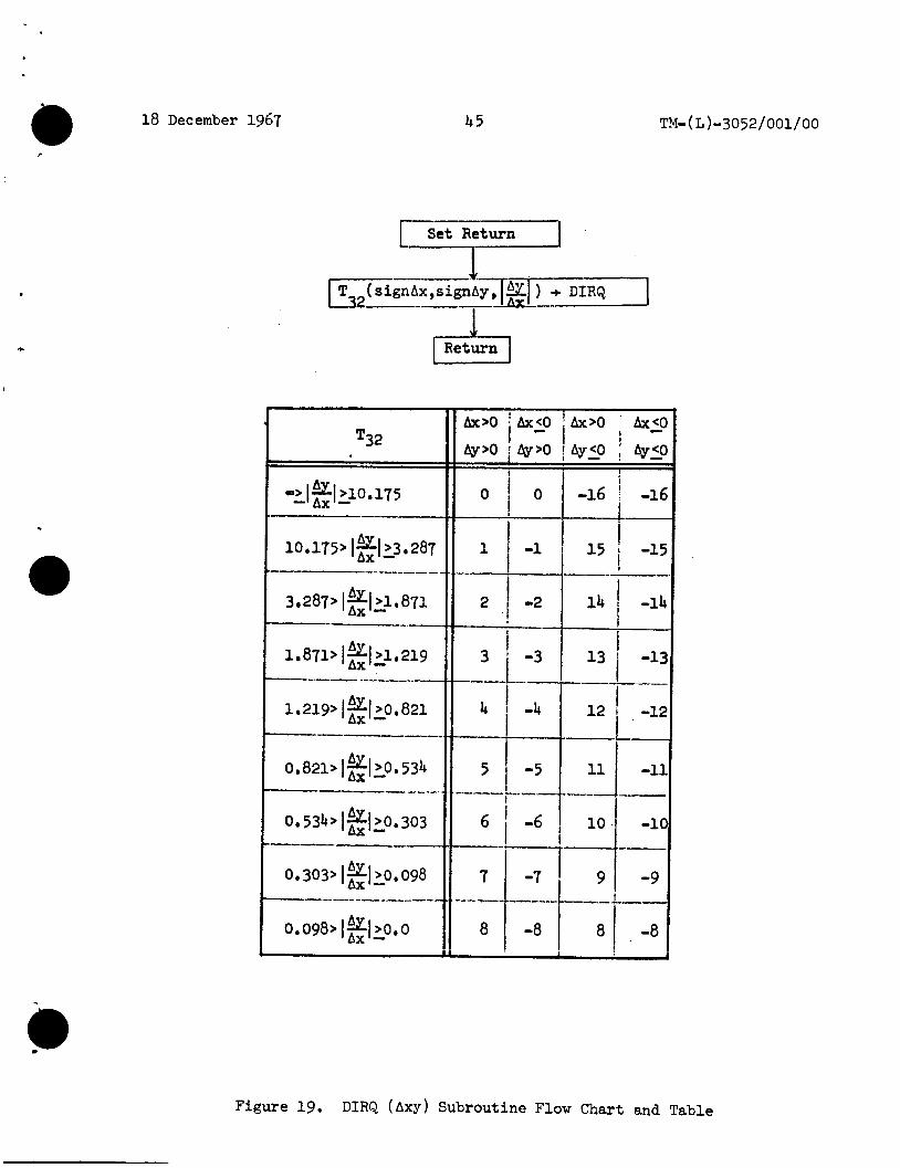
Represents the heading-as computed by the function DIRQ ( A x y )--between two points . are shown in the table as signed integers, those numbers are actually treated as signed two's complement fractions for computational purposes.
Though the values
The signed difference between two headings, h The sign indicates the direction of rotahon
(minus for counter-clockwise and plus for clock- wise), and the magnitude represents the amount of directional change. putation is done on signed two's complement fractions, the largest change that can occur is 180°, indicated by a -1 (-16 in the DIRQ table of values, tj2).
and
h2
Note that since the com-
Stands for stroke. made up of the ordered set of coordinates, p, input to the program between the sequence of pen switch on and pen switch off.
In our program, a stroke is
Used in their usual mathematical meaning. either is agpifcd to a stroke, S, the x and y coordinates are treated independently. Therefore, min (P ) means rnin (xi) and min (yi); max (Pi) has a similar meaning.
When

18 December 1967
eo
Size ( A )
Ch -
10 TM-( L)-3052/001/00 W
The minimum rectangle surrounding t h e set of points , Z, which may be a s t roke, S, or a subset of t h e s t roke, Usually t h a t subset t h a t cons t i t u t e s a feature R ( Z ) i s obtained by computing Min(2) and Max(2) and i s a p a i r of ordered p a i r s (xmin,ymin),
( X m a x 'ymax 1. . The center of t h g Zinimum rectangle R(2) . an ordered p a i r X,Y.
It is It i s computed as 1/2(xmin+Xmin),
An ordered p a i r of differences, x y , specifying the size of an e n t i t y A, from R ( A ) . i s S ize (R(S)),
AY=Ymax-Ymin
Stands f o r character. Ch is u e e d t o specify an output character , and may only be a leg i t imate member of the output character set ( t h e set from which t h e user def ines h i s input ) . t o specify an input character , and is a co l l ec t ion of from one t o n s t rokes , (So, S1 ...S ).
It is usual ly computed The notat ion used i n t h e flow char t s
It i s computed as Ax=xmax-xmin,
Note t h a t both Ax and Ay are 20.
0
Chl i s used
n
Represents output from the ANALYZER rout ine other
*
than a are :
- - =0
u = 1
- - u2
0 Ch . Five u values have been used. They
a s t roke with too many features o r ( i n t h e SAMPLE rout ine) a ChI with too many s t rokes.
a s t roke o r charac te r not found i n t h e dict ionary; thus , an undefined character .
a s t roke o r charac te r i n t h e d ic t ionary t h a t ends a t an intermediate node, has no
Ch at tached, and i s , therefore , an in t e r - mediate, undefined character . For example, if t h e first sample provided t o SAMPLE were a four-stroke M and t h e d ic t ionary were empty, t h e f i r s t t h r e e s t rokes entered would have a u s t roke would have t h e ChO "M" appended as i t s def in i t ion .
0
appended t o them; the four th 2

18 December 1967 11
u = end of strokes o r a vacuous stroke. 3
ah = an inva l id s t roke, defined as one f o r which p1+1 Ax+Ay 130 f o r any adjacent p a i r , pi,
Represents t h e ANALYZER output f o r S. have 0 as an intermediate value, but i t s f i n a l
value is always e i t h e r Ch' o r 0 .
A ( S ) may
4. PROGRAM DESCRIPTION
4 , l DATA FLOW
Ignoring those portions of t h e implemented program t h a t are used f o r t e s t i n g and debugging, w e s h a l l describe t h e sequence of events t h a t t ake place during t h e execution of t h e program, both input data and cont ro l s ignals , w i l l be described.
The f1ow:of data through t h e system, including
The over-all functioning of t h e system involves th ree hardware un i t s , p lus t h e software of t h e time-sharing system. The th ree hardware u n i t s are: (1) t h e PDP-1 computer, which interfaces and buf fers a l l i n t e rac t ive input and output; ( 2 ) t h e Input Memory, a 16 K core s torage module of 48-bit words t h a t is d i r e c t l y addressable by both the PDP-1 and Q-32 computers; and (3) t h e Q-32 computer, a l a rge (65K 48-bit word), fast (2.5-psec cycle t i m e ) , general- purpose d i g i t a l computer on which TSS runs.
The Input Memory can be d i r e c t l y read by an object program running under t h e Time-sharing System i n t h e Q-32, but only t h e TSS supervisor may w r i t e i n Input Memory, Because the re a r e no user programs running i n the PDP-1, t h e r e are no r e s t r i c t i o n s on i t s use of Input Memory.
The Graphic Tablet Display Console, around which t h i s program i s constructed, i n t e r f aces with t h e above hardware as follows: 1010A) used f o r input i s connected t o t h e PDP-1 through a hardware in te r face , Each t i m e an input i s ready at t h a t in te r face , t h e PDP-1 i s interrupted, These in t e r rup t s occur a t two d i f fe ren t rates: every 30 m s when t h e tablet 's pen switch i s o f f , and every 4 ms when it i s on, This pen switch on rate i s va r i ab le between 1 ms and 16 ms. samples grea te r than 4 ms apar t would not provide adequate data.
t h e RAND Tablet (Grafacon
The 1-ms rate cannot be handled by t h e PDP-1;
8
18 December 1967 12 TM-( L)-3052/OO1/OO
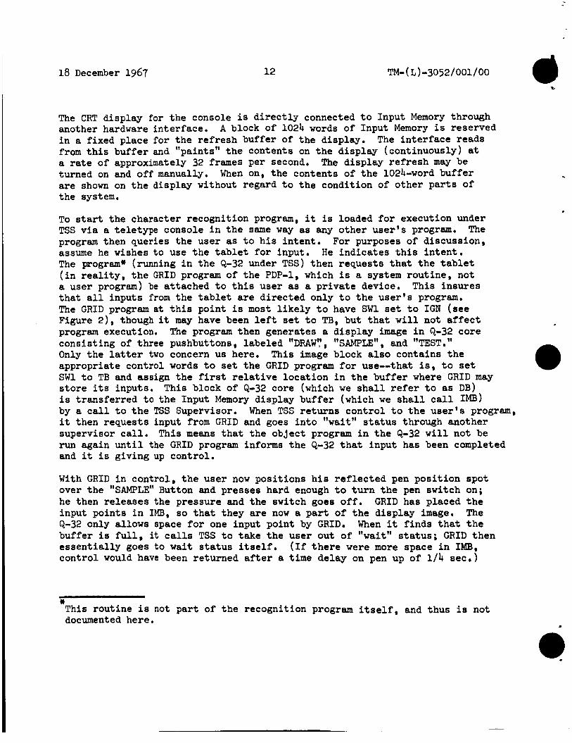
The CRT display f o r t h e console i s d i r e c t l y connected t o Input Memory through another hardware interface. i n a fixed place fo r the re f resh buffer of t h e display. from t h i s buf fer and "paints" t he contents on the display (continuously) at a rate of approximately 32 frames per second. turned on and off manually. When on, the contents of the 1024-word buffer a re shown on the display without regard t o the condition of other p a r t s of the system.
A block of 1024 words of Input Memory i s reserved The in t e r f ace reads
The display refresh may be
To start the character recognition program, it is loaded f o r execution under TSS v i a a te le type console i n the same way as any o ther user ' s program. The program then queries the user as t o h i s in ten t . For purposes of discussion, assume he wishes t o use t h e tablet f o r input. He indica tes t h i s i n t e n t . The program* (running i n the Q-32 under TSS) then requests t h a t the t a b l e t ( i n r e a l i t y , the GRID program of the PDP-1, which i s a system rout ine , not a user program) be at tached t o t h i s user as a p r iva t e device. t h a t a l l inputs from the tablet are d i rec ted only t o t h e user ' s program. The GRID program a t t h i s point is most l i k e l y t o have SW1 set t o I G N (see Figure 2) . though it may have been l e f t set t o TB, but t h a t w i l l not a f f e c t program execution, The program then generates a display image i n Q-32 core consis t ing of three pushbuttons, labeled "DRAW',', "SAMPLE", and "TEST." Only t h e la t ter two concern us here. appropriate control words t o set the GRID program f o r use-=that is, t o set SW1 t o TB and assign t h e first r e l a t i v e loca t ion i n t h e buffer where G R I D may s to re i t s inputs , T h i s block of Q-32 core (which w e s h a l l refer t o as DB) i s t ransfer red t o t h e Input Memory display buf fer (which w e shall c a l l Im) by a c a l l t o t h e TSS Supervisor. it then requests input from GRID and goes i n t o " w a i t " s ta tus through another supervisor c a l l . This means t h a t t he object program i n the Q-32 w i l l not be run again u n t i l t h e GRID program informs the Q-32 t h a t input has been completed and it i s giving up control.
This insures
T h i s image block a l s o contains t h e
When TSS returns cont ro l t o t he user ' s program,
With G R I D i n control, t he user now posi t ions h i s r e f l e c t e d pen pos i t ion spot over t h e "SAMPLE" Button and presses hard enough t o t u r n the pen switch on; he then releases the pressure and the switch goes o f f . GRID has placed t h e input points i n IMB, so t h a t they are now a p a r t of t h e display image. The Q-32 only allows space for one input point by GRID. When it f inds t h a t t he buffer i s f u l l , it c a l l s TSS t o take the user out of " w a i t " s t a t u s ; GRID then e s sen t i a l ly goes to wait s t a t u s i tself . (If t h e r e were more space i n IMB, control would have been returned after a time delay on pen up of 1 / 4 s ec I )
* This rout ine is not pa r t of t he recognition program i t s e l f , and thus i s not documented here

c
18 December 1967 13
The user i s informed t h a t control has returned t o t h e (2-32 by the lack of the moving spot r e f l ec t ing h i s current pen posi t ion, Note t ha t it i s possible t o enable G R I D t o accept inputs without pu t t ing t h e Q-32 program i n t o " w a i t " s t a tus , but we have not t r i e d t h i s , even accidental ly . If t h i s were done, t he two programs ( G R I D and t h e user ' s program i n the Q-32) could get out of synchronization and both end up waiting f o r each other , thus e f f ec t iv2 ly k i l l i n g t h e program,
The Time-sharing System next takes the user ' s Q-32 program out of "wait" s ta tus . coordinates i n terms of button position, and ei ther r e j e c t s o r accepts them, If t h e input i s re jec ted , t h e program simply goes back t o t h e beginning, rewrites Input Memory, c a l l s G R I D and waits, If t h e inputs are accepted, the program named i n t h e button pushed ( i n t h i s case, SAMPLE) i s ca l l ed and cont ro l passed t o it.
The program reads t h e pen input from Input Memory, decodes t h e
SAMPLE (see Figure 4) generates its i n i t i a l frame in DB. t he buf fer block appropriately, it sets the t i m e delay (TD) t o 2 seconds, t u rns t h e smoothing f l a g (SMFLG) on, c a l l s t h e supervisor t o write DB i n t o IMB, c a l l s GRID, and goes i n t o "wait"status.
Having divided up
The user next sees a new display (see Figure 3). t o change the keyboard displayed, o r draw a character i n t h e wr i t ing area. G R I D r eac t s the same way as above. say a ")". t o show on the display before he proceeds. draw o r push a button before GRID has given up control , he w i l l add information t o t h e input t h a t he has not intended and may-as a result--unknowingly add a meaningless character def in i t ion t o the dict ionary, When cont ro l i s returned t o SAMPLE by the system, it checks the v a l i d i t y of t h e input as a function of both t h e s e t t i n g of CIISW, and t h e pos i t ion of t h e i n i t i a l and f i n a l Coordinates of t he first input stroke. ( A stroke i s defined as a l l of t h e input occurring between pen switch on and pen switch o f f ) .
H e may then push a button
Assume t h a t t h e user has drawn a character , The user should then wait f o r some response from t h e Q-32 program
If he inadvertently starts t o
Finding a va l id s t roke , SAMPLE c a l l s ANALYZER. t h e r e s u l t a n t feature s t r i n g searched f o r i n the dict ionary. when SAMPLE i s i n control , ANALYZER processes a l l s t rokes before re turning, on the assumption t h a t a l l of t h e input belongs t o one character . Since t h e user ' s d ic t ionary i s empty, t h e input w i l l not be found, s p e c i a l character "m'' t o t h e display image, re loca tes t h e INKORG so t h a t t h e inputs w i l l not be erased, s e t s t h e CHSW t o U, writes DB i n t h e IMB, c a l l s GRID and w a i t s . draws another character or pushes t h e wrocg b~+.+;on, h i s inps% w i l l be erased and t h e program w i l l w a i t f o r another input ,
The s t roke is analyzed and Note t h a t
SAMPLE adds t h e
The user must now "push" one of severa l buttons. If he
18 December 1967 14
After completing t h e dict ionary, the user makes an input at coordinate 0.0, This , i n essence, causes SAMPLE t o re turn cont ro l t o t h e program t h a t ca l l ed it--the cont ro l program of three pushbuttons, input a t 0.0 i n t h i s control program, he would re turn cont ro l t o t h e t e l e type ,
If the user were t o make an
The difference between SAMPLE and TEST i s t h a t t he re are no inva l id inputs t o TEST. Multi-stroke inputs are not treated as a s ingle character.
The a b i l i t y t o erase or replace an output character from the display i s not c ruc ia l t o the objectives of the TEST. user-constructed dictionary. provide a more r e a l i s t i c usage environment, and t o c rea te a better demon- s t r a t i o n veh ic l e , same posi t ion as t h e input character aids i n c rea t ing t h e proper atmosphere. These capab i l i t i e s were added t o TEST i n order t o solve some of t h e known problems t h a t w i l l occur when t h e character recognizer i s used as a t o o l f o r an ac tua l problem solution.
Its main function i s t o test t h e Replacement and erasure were incorporated t o
Generating an output character of t h e same s i ze and at the
A l l of the information concerning output chr rac te r pos i t ion , s i z e , and locat ion i n the output buffer i s placed i n DLIST, which i s a simple l inked l i s t , ex terna l t o the ac tua l buffer. DLIST could have been implemented i n several ways. The l inked l i s t w a s a design choice,
I f t h e user then pushes "TEST", cont ro l w i l l be turned over t o t h e TEST program (see Figure 7) TEST sets up DB i n two portions: (1) a simple l inked l i s t t o minimize wasted space i n displaying a r b i t r a r y charac te rs i n 5 x 7 dot matrix form, and ( 2 ) a block reserved f o r "ink".
Assume t h a t t h e user draws
C A T This takes f i v e strokes, moved from IMB t o DB, and ANALYZER is ca l led . TEST i f one of several events has occurred: have been processed; ( 2 ) t h e matching f ea tu re s t r i n g i n t h e d ic t ionary has no successor s t roke appended t o it; (3) t h e next s t roke processed does not match any of the successor s t rokes o r it cannot match a first s t roke; ( 4 ) t h e input has too many features and i s thus considered a "scrub" o r erasure, o r it has a noisy point and i s considered inva l id , One of t h e r e s u l t s of t h i s kind of i n t e rac t ive Control i s t h a t a non-recognized s t roke can change the "meaning" of t h e remaining s t rokes from t h a t intended. Each t i m e ANALYZER r e tu rns cont ro l t o TEST, TEST adds o r deletes charac te rs i n DB; only when a l l s t rokes are processed does t h e r e s u l t appear on t h e use r ' s d i sp lay , replacing h i s hand- drawn input,
When GRID r e tu rns cont ro l t o TEST, t h e inputs are ANALYZER re turns cont ro l t o
(1) a l l of t h e s t rokes i n DB
If a l l goes w e l l , t h e user w i l l see .... pt q? 1.d €7 J.
.
.
,

4
.
18 December 1967 1 5
appear at once i n the display, although each character was placed i n DB as it was recognized and returned by ANALYZER.
To i l l u s t r a t e what can happen i f a s t roke i s not found, assume t h a t t h e user draws the following: C a
T on t h e tablet i n t h e order,C , t he "," of the "A" i n t he dictionary.
,= ,- , I , and the ANALYZER could not f i nd The user would see e i ther
i.... *...a
..-. I,.: ..... SD...
. . or . e,. C... ..L.
.i
.I. 'I ...
depending on where the center of the "n" i s wi th respect t o the two s t rokes t ha t are not taken as an "="* most l i k e l y case.
The first of these two i l l u s t r a t i o n s shows t h e
4.2 RESPONSE TI1433
We have been able t o provide instantaneous response i n the one c r i t i c a l area required-namely, feedback from pen inputs t o t h e display so t h a t "ink" flows from t h e "pen" i n real t i m e .
Response t i m e f o r t h e user upon completion of input i s a function of many var iables . t h e longer t h e delays. I n par t icu lar , t h e more people using tape and d i sc , the longer t h e delays, are t h e po ten t i a l delays. The e f fec t of t h i s f ac to r i s hard t o measure because of t h e other var iab les , but i f the processing takes more than one quantum of in t e rac t ive user t i m e (cur ren t ly about 600 m s ) , t h e user i s swapped out and i s a t the bottom of t he in te rac t ive queue f o r one cycle.
Naturally, t he more in te rac t ive users t he re are on t h e system,
Also, the more input t he re i s from t h e tablet , the longer
In general , when there a re l e s s than 20 other users on t h e system, response i s acceptable (though not instantaneous) on the system, response i s slow enough t o be annoying; when there are more than 30 users on, response i s intolerable .
When the re are more than 25 users
If the SDC Time-sharing System had provisions f o r p r i o r i t i e s among t h e in t e r - a c t i v e users , some of these annoyances could be lessened, but it doesn' t and so from t i m e t o t i m e w e w i l l be annoyed.

18 December 1967 16 - 0 TM-( L)-3052/001/00
5 . DESCRIPTION OF PROGRAM SEGMENTS
5 . 1 GRID SUBROUTINE
G R I D i s a program that runs on t h e PDP-1 and provides the in t e r f ace between the RAND Tablet and the Q-32 Time-sharing System.
A l l communication between G R I D and t h e ca l l i ng program takes place v i a the Input Memory Buffer (IMB), (SMFLG, TD and INKLOC) i n t h e cont ro l words and GRID places t h e tablet input da ta ( ink ) i n the buffer beginning a t the loca t ion spec i f ied i n INKLOC, The format of these inputs i s shown i n Figure 1,
The c a l l i n g program suppl ies t h e var iab les
A flow chart of the GRID subroutine i s shown i n Figure 2, It is not e s s e n t i a l t ha t t h i s routine s t a r t with SWI at I G N , s ince t h e time-out on TD guarantees t h a t SWI cannot remain inde f in i t e ly i n the TB pos i t ion i f any inputs have been made, regardless of t h e state of t h e Q-32 program. Note t h a t t h e PDP-1 i s in te r rupted at two d i f f e ren t in te rva ls : switch) is on, and at 30-ms in t e rva l s when psw i s o f f ,
a t 4-ms in t e rva l s when psw (pen
SW2 i s set when psw is first detected, This saves both t i m e and space, because of t he way t h e PDP-1 reads Input Memory, (enabled when SW2 is set t o "on") merely replaces t h e o ldes t xy with t h e one j u s t r e a d , t h e n computes t h e average xy as output. as a r ing counter, modulo 8,
The smoothing algorithm
The index j i s operated
The value of 3 used i n t h e f i l t e r was ar r ived at empir ical ly f o r drawing very small characters (using no smoothing), smoothing using a f i l t e r value of 2,
Unti l recent ly , Ns has not been implemented properly, thus it is used only
by time-out t e s t ing i n G R I D and not by t h e Q-32 rout ines . t h a t could have been included, had space been ava i lab le ( t i m e was no problem) fi i s the computation of t h e minimum rectangle surrounding each s t roke , R(S). This would have saved some t i m e i n the Q-32 programs, at the cos t of buf fer space i n the INK area,
Small characters could be drawn w i t h Ns is t h e number of s t rokes input.
Another funct ion
5.2 SAMPLE SUBROUTINE
The SAMPLE subroutine i s used t o bui ld and tes t d i c t i o n a r i e s i n a one-character- at-a-time mode. character (multi-stroke characters are allowed) o r pushing a button.
This program allows only one ac t ion at a time-drawing a
.

h
18 December 1967 17
Byte
I I
INKLOC
4
1023
I PC X Y M
INKLOC I TD I TB Location
Typical Display
by INK *Word Inser ted
Figure 1. Storage Map f o r Display Buffer (DB) and Input Memory Buffer (IMB)

TM- ( L ) -30 52 / 001/ 00 18 December 1967 18
.
--4dCN no
SW1 * TB Return "r". r?
o + ri, TD * TD' .
I 1
I
Is paw on? I I 1
d Is N, a O?
yes I
SVl + IEU'K 0 + 1x3
IKiOC + i
x,y,M=l .+ IEZi -.
XY + XYp
0 + Po i+1 + i
Is i = end? i
I no I
I
Call TSS t o Sc;?ed-.ile Waiting Pro;;ran I +--I Return
4 - l Return
Figure 2. GRID Subroutine Flow Chart

,
c
I
18 December 1967 19 TM-( L)-3052/001/00
Figure 3 shows a layout of t h e d isp lay- the user sees when t h i s program i s called. The user can then select one of f i v e keyboards. The f i v e keyboards contain (1) d i g i t s , brackets, and r e l a t iona l s ; (2) upper-case Roman letters; ( 3 ) lower-case Roman l ' e t te rs ; ( 4 ) punctuation and spec ia l marks; ( 5 ) Greek letters. The maximum number of characters per keyboard i s 26.
A flow chart of t he SAMPLE subroutine i s shown i n Figure 4. flow chart concerned with t h e detai led control of t h e Display Buffer indicate when various strokes a re l e f t and when they are erased. as shown i n Figure 5.
Those pa r t s of t h e
The buffer i s al located
Communication between SAMPLE, ANALYZER, and DEFINE i s through the inputs i n t h e DB and a set of standard global communication r e g i s t e r s plus, of course, t h e computer's accumulator.
When an input is found i n t h e dictionary as a defined character , t h e output character replaces t h e input at t h e same place on t h e display a t approximately t h e same s ize . one of two spec ia l characters , " 2 '' o r ' I - " , i s output at t h e ILgC (a posi t ion on the display surface) (see Figure 1 ) .
If t h e input i s not defined, it i s permitted t o remain and
The CALL G R I D AND WAIT i s a Time-sharing System dispatcher ca l l . could be given without a wait , but there i s nothing t h a t needs t o be done i n t h e in te rva l ; a l s o synchronization between t h e two programs would be more d i f f i cul t .
The c a l l
Although not shown i n Figure 4, t he re i s a small master program t o which SAMPLE and TEST ( see below) exit when the input s t roke i s found t o be on the 0 ,O coordinate of t h e t ab le t .
5.3 TEST SUBROUTINE
TEST allows the user t o t es t a dictionary i n a multi-character, in te rac t ive mode. In addition, it provides two ed i t ing features: replacement of an ex i s t ing character with an input, and erasure of one o r many characters with one scrub. A flow chart of the subroutine i s shown i n Figure 7.
The mode f l a g i s set t o " tes t" so t h a t ANALYZER does not assume t h a t a l l of t h e input strokes cons t i t u t e one character.
The Display Buffer f o r TEST i s organized as shown i n Figure 6.
The Display L i s t (DLIST) i s a linked l i s t of output characters and other information required fo r physically locat ing t h e individual characters on t h e display surface.

18 December 1967
Function Buttons (FBI )
. Clear
. Redef ine
Writing * Ares
20
Keyboard Keyboard Button Area Chenge
Button Posit ions (KBI) Buttgps I 1 , 1
8 8 (3 @ii@ 0 Ga @ 6 Q (3 0 0 i D t l I
i u 8 0 0 0 Q Q 0 0 @ @ 8 a 0 : P G R * : ILOC ....----..-..-
T
Figure 3. Display for SAMPLE Progrem

18 December 1967 21
Set Return u Generate FBs, DCBs i n DB
KBS o r i g i n + KB@
C H ~ origin + ~ C H Ink or ig in -* BINK + INKBRG
CHSW + N
1 Generate KBs ( n ) a t KBg i n DB 1
I DBO, 1023 IBMO, 1023
I Call G R I D and W a i t
I ~ I N K ~ R G , INKLOC DBINK~RG, INKLOC
y i s I
I Return I no I
Figure ha. SAMPLE Subroutine Flow Chart

18 December 1967 22 TM- (L )-3052/001/00
R CHSW
Yes . . .
, Enter ANALYZER IS AO(S) a
1 Enter DEF
).' . ',I
A
I no I
I Yes
I
#
Figure kb, SAMPLE Subroutine Flow Chart (continued)

18 December 1967 23
0 1
8
~ ~~ ~
Control Word
Permanent Buttons
(FBS and KCFs)
Keyboard Buttons
(KBS)
Out put Character ( OCH)
INK Area
1023 Control Word
Figure 5 . Display Buffer Allocation f o r SAMPLE
0 1
102:
Control Word
Permanent Image ( T i t l e and Function Button)
Linked L i s t f o r
Output Character Generator
I N K Area
Control Word
Figure 6. Display Buffer Allocation f o r TEST

18 December 1967 24 J
TM- ( L ) = 30 52 / 001 / 00
P 4
Generate T i t l e a d FB ( c l e a r )
Ink Origin * BIMK Link DB Chfl Block Generate Chfls on DLIST i n DB Chg Block
Se t Origin of Ch 8 Block i n DB
I I
1
BINK * INK@RG DBINC@EIG, 1023
TD, S f l g , INKORG * D3 Control Wds
DB0,1023 * ImO,1023 Call G R I D and Wait
yes I
1-1 I L
h Return
.c IS so on FBC Clear?
I Yes
1
Clear DLIST *e I ~ I N K C ~ R G , IMKLW * D B I N C ~ ~ R C , I ~ K L B C
I I
6 Figure 7a. TEST Subroutine Flow Chart
\
a
18 December 1967 25 TM-( L)-3052/001/00
Y
I 1 i
I 1 O Compte + ScrubfPe Ch size from Ro(S)
I
c Are m y DLXST entries inside Rg(S)?
I I I iO
I y&s I *
Delete DLET entries and Lnhfls from DB I 1 1 Is Scrubflag = O? I
I Yes
I n.0 1 Ad5 Ch to DLIST arid DB
A I Are all Strokes processed? i I I
yes no
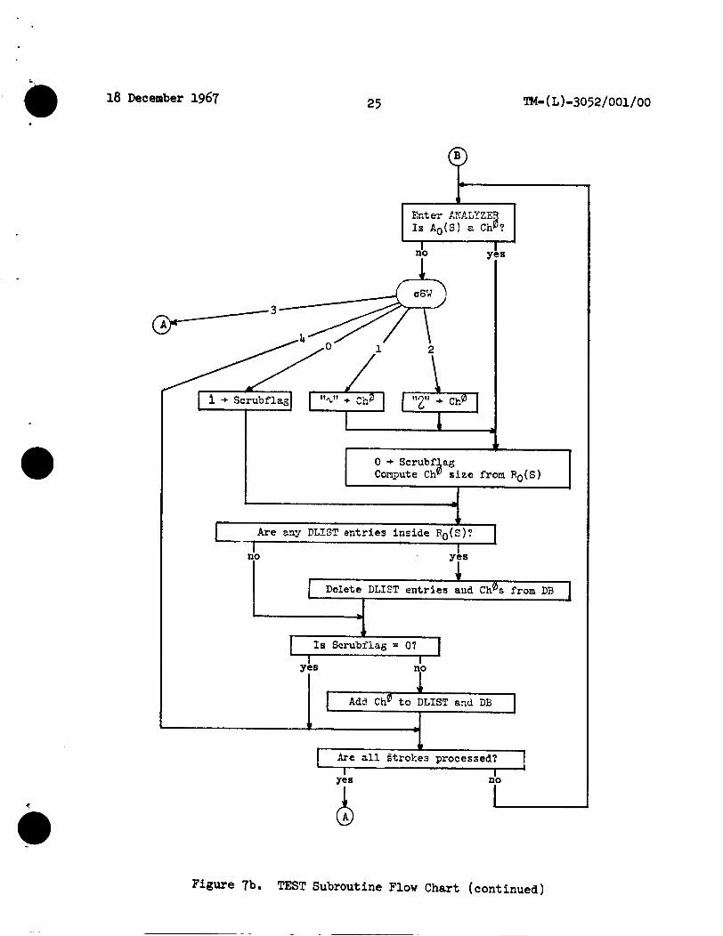
Q Figure 7b. TEST Subroutine Flow Chart (continued)
18 December 1967 26 TM-( L)-3052/001/00
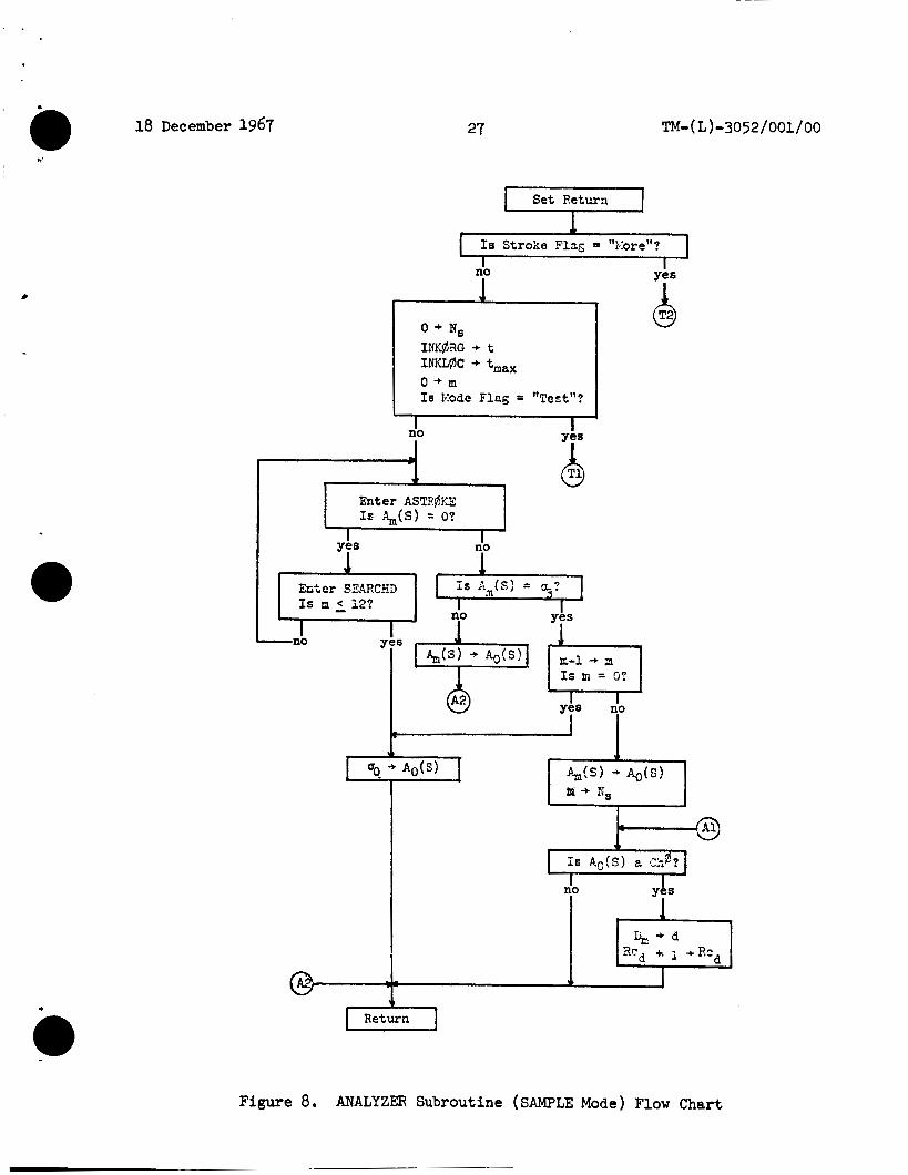
Each element contains t h e following:
1. Location of t h e lower left-hand corner of t h e output character.
3. A pointer i n t o the Display Buffer t o t h e o r ig in of t h e points forming the output character.
4. The output character code,
5 . A l i n k t o t he next i t e m (0 ind ica tes t h e end of t he Display L i s t ) .
The l imited ink space i n t h e Display Buffer ( ac tua l ly t h e I M Buffer) allows input of 6 t o 8 small characters , 3 o r 4 medium-sized Characters, 1 o r 2 la rge characters , and 1 or less very la rge characters , (This l imi t a t ion o r extra-large characters i s a problem. )
When an output i s passed t o TEST from ANALYZER, t h e display l ist i s searched t o see i f any characters are t o be deleted. The t e a t is performed by computing t h e center of the character on the DLIST and comparing t o see i f it l ies within the minimum rectangle surrounding t h e input, R(Chl). All characters f o r which t h i s i s t r u e are deleted from the DLIST and DB.
Although the program cur ren t ly outputs one of two spec ia l characters on t h e display ( "2 " o r "-") when an unknown character occurs, it may ac tua l ly be preferable t o do nothing, t h a t is , t o ignore t h e input , For t e s t i n g and debugging purposes, though, these spec ia l characters have been of value,
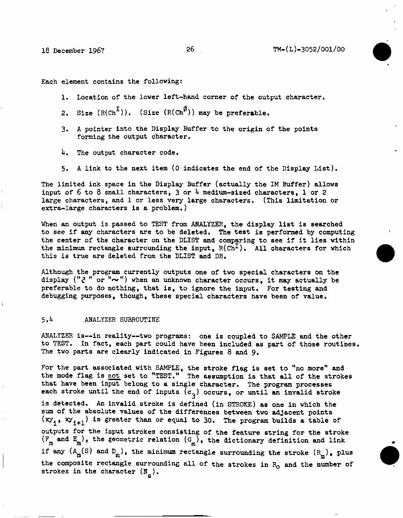
5.4 ANALYZER SUBROUTINE
ANALYZER is--in reality--two programs: t o TEST. The two pa r t s a re c l ea r ly indicated i n Figures 8 and 9.
one i s coupled t o SAMPLE and t h e o ther In f a c t , each pa r t could have been included as pas t of those rout ines ,
For t h e par t associated with SAMPLE, the s t roke f l a g i s set t o "no more" and the mode f l a g i s not set t o "TEST." t h a t have been input belong t o a s ing le character . each s t roke u n t i l t h e end of inputs (u ) occurs, o r u n t i l an i nva l id s t roke
i s detected. sum of t h e absolute values of t h e differences between two adjacent po in ts ( x y xy i s greater than o r equal t o 30, The program bui lds a t a b l e of
outputs for t h e input s t rokes cons is t ing of t h e feature s t r i n g f o r t h e s t roke
( Fm m
The assumption i s t h a t a l l of t h e s t rokes The program processes
3 An inval id s t roke i s defined ( i n STROKE) as one i n which t h e
i' i+l
and E 1, t h e geometric r e l a t i o n (C, ) , t h e d ic t ionary d e f i n i t i o n and l i n k -.-
if any (Am(S) and D m ) , t he minimum rectangle surrounding t h e s t roke ( R m ) , p lus the composite rectangle surrounding a l l of t h e s t rokes i n % and t h e number of s t rokes i n the character (Ns).
18 December 1967 0 27
1 Set Return I
nb
-Ti0 I Y)S
I
Q
I no I
Enter SXARCSD is A (s) = 0-?
Figure 8. ANALYZER Subroutine (SAMPLE Mode) Flow Chart

Entcr EIdVE
h t e r HOVE
1
28 18 December 1967
P Q "NO More" + Stroke Flag
Enter SEARCBD
P I I no Yea I
Entcr EIdVE + 1
Is m - 17 ,*,
I
C
Figure 9. ANALYZER Subroutine (TEST Mode) Flow Chart

c
&-
Second, STR(bKE r e - f i l t e r s t h e points so t h a t none are c loser than two r a s t e r u n i t s , and computes t h e heading ( h ) (one of thirty-two) from point t o point and t h e heading differences (Ah) f o r use by the corner de tec tor and f ea tu re ex t rac tor . It i s here t h a t inva l id s t rokes are discovered.
18 December 1967 29 TM- ( L ) -30 5 2 / 001 / 00
The control f o r the TEST portion of ANALYZER i s much more complex. only determine when an output character i s ready f o r output from t h e r e s u l t of the dict ionary search. legi t imate character t h a t it found, i n some cases. It r e tu rns cont ro l t o TEST each t i m e it has an output ready, which may be a leg i t imate character
(a Ch ) , and intermediate but undefined node i n the dict ionary ( a '' 2 "), an undefined input (u2, output as "N " ) or a scrub s t roke (uo* too many
f ea tu res ) , in te rpre ted by TEST as an erasure, o r the end of input ( a ) . 3 inva l id s t roke (CY, , ) i s ignored.
i n t h e first en t ry of a l l indexed l ists , A o ( s ) , R o ( s ) , and Fo(s).
It can
Thus, it must be able t o back up t o the l as t
0 output as 1,
An
A l l of t h e per t inent data f o r TEST is placed
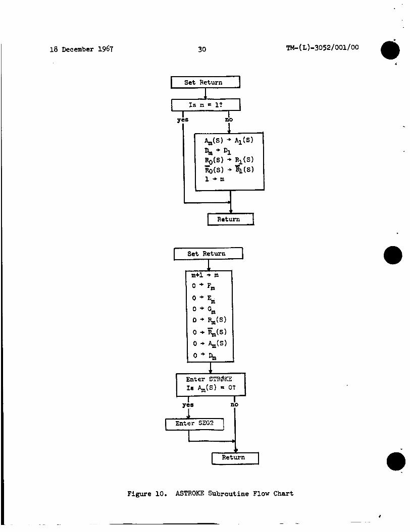
5.5 ASTRPrKe AND STROKE SUBROUTINES
ASTR(bKE is merely a mechanism by which STRCdKE can be changed, modified, o r replaced without changing ANALYZER (see Figure 10.) It c l e a r s the current items i n the l is ts indexed by m (having f irst incremented m ) and decides whether o r not t o c a l l t h e feature-extraction rout ine, i n t h i s case, SEG2. If t h e system had various feature ex t rac tors f o r d i f f e ren t alphabets (and thus d i f f e ren t d i c t iona r i e s ) , t h e dict ionary would be queried here as t o what fea ture ex t rac tor t o c a l l .
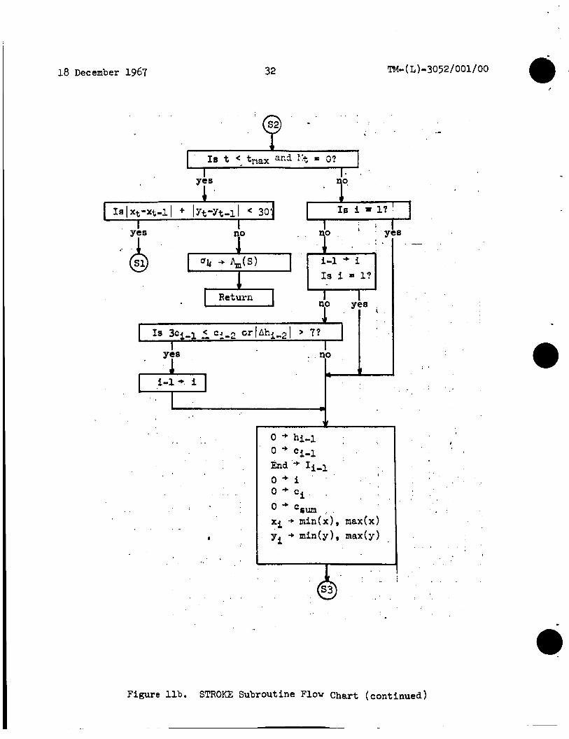
STR$KE does three things ( see Figures l l a and l l b ) . data. It has become apparent only s ince we have had the PDP-1 smoothing rout ine working that pos t - f i l t e r smoothing is of value, pa r t i cu la r ly i n making corner detect ion better and i n giving a smoother path so tha t a simpler (and faster) fea ture ex t rac tor c a n be used.
F i r s t , it smooths t h e
The smoothing algorithm i s a - -
- - '1 + '2'2 , where p i s t h e point xy and C (denoted c + c2 'smoothed simple one:
1 as Pc i n t h e GRID program) is t h e count associated w i t h it.
Third, STRgKE computes t h s minimum rectangle surrounding the s t roke R ( s) , t h e center of t h a t rectangle R ( s ) , and the Size (S) and average point count IC) fo r QEe %y the corner de tec tor , computation by eliminating high-coknt (slow-path) points from t h e average, i n order t o get a more consistent C.
We h w e recer?+,lg decided ts m d i f y t h e C
18 December 1967 30 a TM- ( L)-30 52/001/ 00
Set Return - -1 Ye'
I B no
I
d Return
Set Return - r"l Return
Figure 10. ASTROKE Subroutine Flow Chart

18 December 1967 4
31
Set Return 1 Is t t,,,. w
no yes I I
P;. + p
C t + c 0 + Ii 0 + hi
I t+l + t
I no I
1 Y&S
A-
I T
i i+i + i 1
Figure lla. STROKE Subroutine Flow Chart
18 December 1967 32 TM- ( L ) = 30 5 2 / 001 / 00
I Ye=
. .
I Is i = 17 1
I
1 I I no yY
i=l+ i
I
. .
. .
_-
: a
. .
I
c
Figure llb. STROKE Subroutine Flow Chart (continued)
~

18 December 1967
L
33 TM- ( L ) -3 0 5 2 / 0 01 / 0 0
, .
.1
Figure llc. STROKE Subroutine Flow Chart (continued)
18 December 1967
Before exiting, Size (S) is something other than a spot period.
34 TM- ( L)-3052/001/00
tested to see that it is large enough to be 6x6 raster units or less, which we take to be a
m e output from STRBKE is the table Pi, Ci, Ahi, Ii, and the quantities
Rm(s), Fm(s), Sizem(S), and Cm(S). -
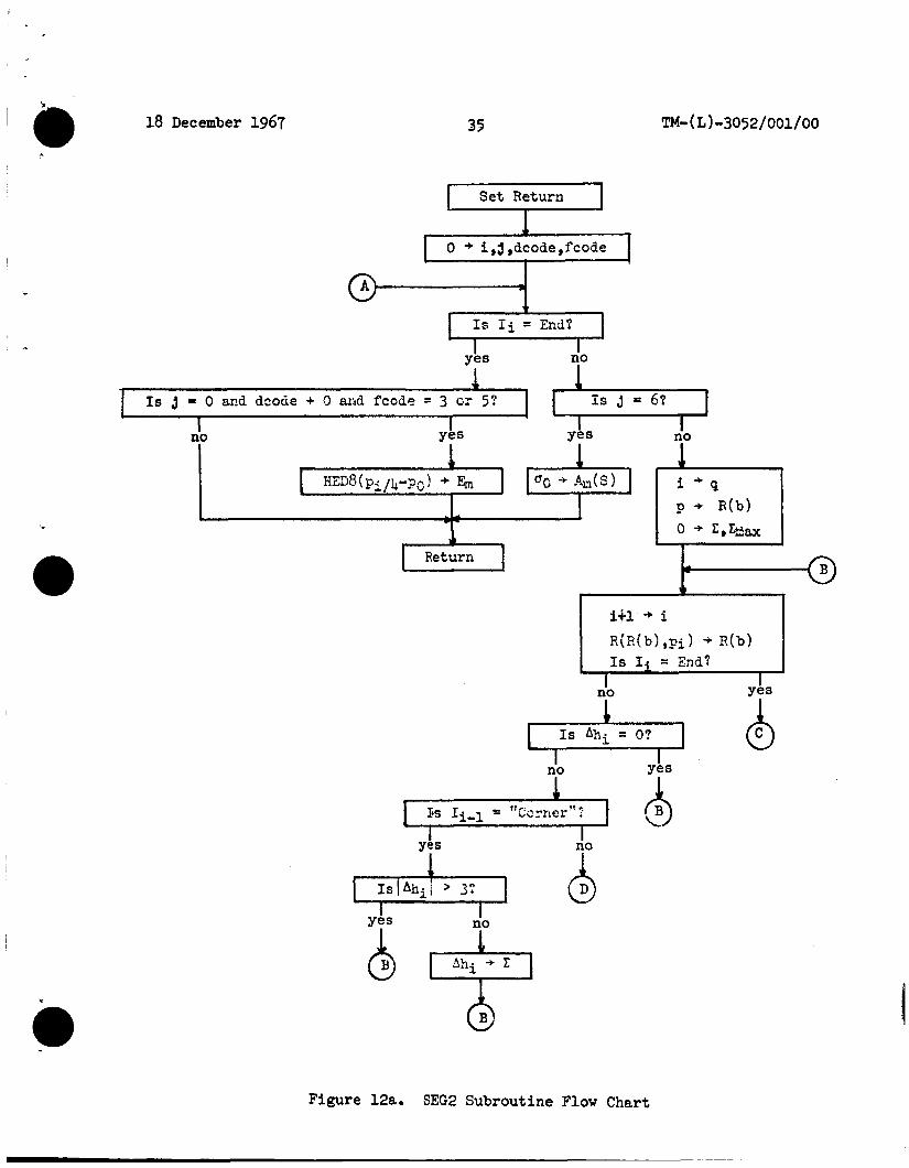
5.6 SEC2 SUBROUTINE
SEG2 is the heart of the program; it performs the feature extraction (see Figures 128, 12b and 12c). This routine has been changed most often, and will continue to be improved. Among currently proposed changes is the elimination of the "loop" feature ( I Z I > 24), because of the problem of discrimination between some characters formed from a single loop. of whether j-0, dcodef0, and fcode = 3 or 5 is an attempt to resolve this by adding (as an additional feature, if this test is true) the heading from the beginning of the stroke to a point % of the way along the path.
The test
The most complex part of the routine is the location and identification of an inflection point. This could be done in other ways, but less efficiently.
This routine computes the minimum rectangle surrounding each feature and the collected rectangle of the predecessor features; it then computes the center-to-center direction for those that are not coincident. No features in a single stroke can be "far" from the collected rectangle of its predecessors. The value of 48 for determining a maximum sum-and thus the limit of a lOOP--iS an arbitrary one, as are the values used for determining the bounds of the other features (line, curve and cup).
The DIRF subroutine, which is called by SEG2, computes the value of dcode. (See Figure 12b. )
The total feature, made up of fcode, dcode and ccode, is appended to the right end of the feature string, but this is not of significance except where another procedure would create an ambiguity or other difficulty.
5.7 SEARCHD SUBROUTINE
SEARCHD is the program that searches the definition dictionary (DICT) for each stroke as it is presented by ANALYZER (see Figure 14) to the calling program after replacing Am(S) with the contents of the definition, and replacing Dm with the definition location in the dictionary (if an exact match is found). and u2 in
It returns control
Otherwise, it returns with a location of 0 in D m
18 December 1967 35
Set Return F 0 + i,j,dcode,fcode
I
I no 1
1 I I IS Ahi O?
6 Figure 12a. SEG2 Subroutine Flow Chart

18 December 1967 36
Q
no no
6
no
TM-( L)-3052/001/00
L
Figure 12b. SEG2. Subroutine F l o w Chart (continued)
~~

c
C C O ~ ~ i
18 December 1967
ccode = 0
37 .
Q
If or i f 24 5 > 12, fcode = 2
or i f 1 2 C > 6, fcode = 1 or if 6: Z > -7, fcode = 4
> 24, fcode = 3
or if -7 o r if -13
> -13, fcode = 7 E > -25, fcode, = 6
else fcode = 5
Enter DIRF
Yes 1
I no I
w I no I
Figure 12c. SEG2 Subroutine Flow Chart (continued)

18 December 1967
+no3 +n-2
38
,
Feature S t r ing I SLink I NLink I G I D e i
a TM-( L)-3052/001/00
+n-1 +n
Figure 13 shows the physical organization of t h e character dictionary. t h e s t roke t o be matched is a successor s t roke, i t s geometric re la t ionship t o i t s predecessors i f first computed i n GREL (see Figure 1 4 ) . l i n k (SLINK) of t he previous s t roke (Dm-l ) i s placed i n t h e index d.
i s a zero, there i s no successor. same l e v e l i f the current one under examination doesn't match. do not use N L I N K , but r a the r successive locat ions i n memory ( f o r t h e sake of speed of search).
f o r t he s t roke i n t he appropriate l i s t , o r t he loca t ion of t h e en t ry (Dm) and t h e contents of the def in i t ion f i e l d , e i t h e r u, or a Ch .
When
The successor
NLINK points t o a l t e r n a t i v e s t rokes a t the F i r s t s t rokes
If it
The search re turns with a u 2 i f it does not f i nd a match
0
t l I t tt tt I t
t f 0 ff tt ,
A
D I CT +1 +2 +3 +4 L- DLOC
r SLOC
F i r s t Strokes
Suc c e s sor Stroke s
Figure 13. Character Dictionary Organization

18 December 1967 39
yes n'0
:I3 Rettzrn
I I
I
.yes no
TM- ( L ) - 3 0 5 2 / 0 01 / 0 0
1) Is d = O?
. -
.
Figure 14. SEARCHD Subroutine Flow Chart

18 December 1967 40 TM- ( L)-3052/001/OO
Set Return - I
Ye8 I
I no I
Y
Y 1 f I6 -.+ c, 2 35:
I
-
YCS
I-
. .
Return
* . a , I
Figure 15. CORNER Subroutine Flow Chart
. .
c

18 December 1967
5.8 CORNER SUBROUTINE
41 TM- ( L ) - 30 5 2 / 0 01 / 00
The CORNER subroutine marks a corner if the local change of direction is greater than a right angle. A flow chart of this routine is given in Figure 15. Otherwise, the velocity is tested (using the best estimate we have, the counts). The test was arrived at empirically, In essence, it follows the rule: the sharper the turn, the faster the turn can be made (and be correctly detected).
This is but one version of CORNER, and works better than most we've tried. It will work with either post-filter smoothing alone or with both smoothing routines in operation. We are working on other versions of corner detection that we hope will prove even more effective.
I Ax
5.9 GREL SUBROUTINE
GREL computes the relationship of two rectangles: current stroke, and the one surrounding all of the predecessor strokes in this character, Figure 17 is a flow chart of this routine. GREL first tests for coincidence using DIRW.
the one surrounding the
Overlap is tested by computing:
Axy = Size (Ro( S) )-Size( RT( S) )-Size( Rm( S) )
Figure 16 illustrates several examples of this computation. has been assigned to proximate rectangles and 24 to those that are distant.
The value 16
_.
AY
Ax and Ay > 0
........a .''T\"I P-fC\ F,(j(s! p I C \ ----- % \ " I
Figure 16. Examples of Overlap Computation

18 December 1967 42 TM- ( L ) 3 0 5 2 / 001 / 00
. .
: . - . . .
I
1 , . I
*I Return.
. yas I
I ' ' no
: I I .)
I . .
1 ' 4 '
. I.
. . . . . .
Figure 17. GREL Subroutine Flow Chart

18 December 1967 43 TM-( L)-3052/001/00
5.10 HED8, DIRQ, DIRW, AND DIRF SUBROUTINES
HED8 and D I R Q are simply a p a i r of table-driven d i rec t ion assignment rout ines and should be self-explanatory (see Figures 18 and 19). DIRW i s used by GREL t o compute t h e value assigned t o the geometric re la t ionship between two rectangles (see Figure 20).
DIRF i s used by the fea ture extractor t o generate dcode, t he r e l a t ionsh ip between t h e beginning and end points of each f ea tu re (see Figure 21). Special consideration is given t o features whose aspect r a t i o i s less than .25 o r grea te r than 4, and t o features t h a t begin o r end on an i n f l ec t ion poin t , DIRF determines i f t h e fea ture began and ended i n t h e same quadrant of t h e rectangle surrounding t h e feature . If it did not, one of e ight values i s assigned. On t h e o ther hand, i f t h e end poin ts are i n the same quadrant but do not meet t h e closure t es t ,
then HED8 i s used t o compute the assigned value. more consis tent than using HED8 alone, because HED8 i s responsive t o s m a l l changes i n aspect r a t i o , whereas DIRF i s not.
This method has proven far
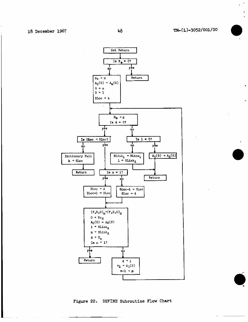
5.11 DEFINE SUBROUTINE
DEFINE adds de f in i t i ons t o t h e dict ionary, the last s t roke of t h e input , inser t ing only those s t rokes t h a t were not found i n t h e d ic t ionary by SEARCHD. If a l l of t he required s t rokes f o r t h e d e f i n i t i o n cannot be added because of in su f f i c i en t space, none are added t o t h e dict ionary, thus eliminating t h e problem of t h e dangling def in i t ion . (See Figure 22 f o r a flow char t of t h i s subroutine.)
The DEFINE rout ine starts w i t h

18 December 1967
I Ax>O Ax40 Ax>O AXLO Ay>O AyTO 1 Ay<O Ay*O - T8 -
i
44 e TM-( L)-3052/001/00
Figure 18. HED8 (AW) Subroutine Flow Chart and Table
~
18 December 1967 4 5 TM- ( L ) -3052 / 001 / 00
c I & ] ) + DIRQ ----Ax-- I I
T32
0
-1
&>O . AXLO
I 15 I -15
I
10.1 -10
Figure 19. D I R Q (AxY) Subroutine Flow Chart and Table

18 December 1967 46 TM-(L)-3052/001/00
Set Return I
! .
Figure 20. DIRW ( A x y , R(S) Subroutine Flow Chart
~

I .
18 December 1967
I Set Return 1
J
n'0
I s 4 9 2 I no 5
47
C
K(r.c) 0 2 2 I 31 5 6 I
0 o 8 2 112 2 1
2 6 ' 7 0 8 1 8 6 7.
- 1 4 0 3 2 1 4 2 3
3 5 6 4 0 5
r -
1 4 6
yes
I
yes I i O I
1
Figure 21. D I R F Subroutine Flow Chart and Table
18 December 1967 48
Set Return F I no b Return
I I Yes no d I8 DLoc *SLbc? I Yh8
I no I
Dictionary F u l l 1 h Te 1 - O?
I no I YCB
I
Return I
SLOC-1 -r S L O C DLoc+l * DLoc
Figure 22. DEFINE Subroutine Flow Chart

c
PSW
osw
P
sw1
18 December 1967 49 TM- ( L ) -30 52 / 001 / 0 0
APPENDIX A: GLOSSARY OF MNEMONICS AND ABBREVIATIONS
TERM MEANING REFERENCE - d, i, J , 1, These l e t t e r s designate indexes t h a t m, f3, r , t are used i n t h e usual programming
They are sense of i t e r a t i o n counts. l o c a l ( i n the ALGOL sense) i n t h a t they are available t o ca l l ed sub- rout ines but not t o ca l l i ng sub- rout ines *
The mechanical switch i n t h e t i p of thb RAND Tablet s ty lus . It has t h e values "on" and "off ."
GRID
The program switch associated with SAMPLE, TEST re turns from ANALYZER t h a t are not
Ch "2", "3", and "4" t h a t are the sub- s c r i p t values of t h e f i v e meanings of u*
0 It has the values "O", "l",
The program switch i n G R I D t h a t i s G R I D set t o t h e appr0priat.e function according t o the value of psw and Td, t he time delay. It has the
value I G N , meaning "ignore t h e t ab le t " ; TB, meaning "post only the current posi t ion of t he pen i n IMB at TB"; and I N K , meaning "fi l ter and post t h e path of t h e pen on t h e t a b l e t as long as paw i s on and there is room i n the buffer"
sw2 The program switch i n GRID t h a t enables o r disables smoothing, It has t h e values of "on" and "off" according t o SMFLG.
G R I D

18 December 1967
TERM
CHSW
-
BINK
ccode
C
dcode
D
DB
DICT
DLQC
DLIST
The program switch i n SAMPLE that controls program flow and the meaning of user act ions a t the tablet. CHSW may be s e t t o "D" meaning "a defined character has been output o r a new def in i t ion added t o the dictionary"; N, meaning "there is no haput" ( t h i s is t h e i n i t i a l condition and t h e condition after a "clear") ; "U" meaning "there is an undefined input pending; and "R", meaning "the function button REDEFINE has been pushed" ,
REFERENCE
SAMPLE
The r e l a t i v e locat ion where "ink" SAMPLE and TEST may begin i n IMB,
A subpart of a fea ture , SEG2
The re jec ted point count provided by GRID and referred t o as Pc in GRID,
STR(bKE
A subpart of a feature , SEG2
The dict ionary pointer associated ANALYZER with a s t roke, indexed by m,
The Display Buffer image res ident with the object program i n 4-32 core
SAMPLE, TEST
The name of t he de f in i t i on dict ion- ==Y *
DEFINE, SEARCHD
The pointer used with DICT f o r t h e next avai lable loca t ion t o s t o r e a f i r s t s t roke ,
DEFINE, SEARCHD
The l inked l i s t of output characters i n TEST containing s i z e and pos i t ion information and t h e r e l a t i v e loca t ion of t h e ac tua l character i n IMB o r DB.
TEST
J

18 December 1967 5 1 TM-( L )-3052/001/0,0
TERM
ecode
- REFERENCE
SEG2
MEANING
The computed geometric re la t ionship f o r E.
E The s t r i n g of geometric re la t ionships between a feature, F, and i t s pre- decessors in a stroke, indexed by m,
ASTR$KE, SEG2, DEFINE, SEARCHD ..
e The subpart of a feature. SEG2 fcode
F The s t r i n g of features for a stroke, indexed by m a
ASTRaKE , SEG2, DEFINE, SEARCHD
FB
G
The abbreviation f o r Function Button, SAMPLE, TEST
The geometric re la t ionship between a stroke and i t s predecessors i n a multi-stroke character, indexed by m.
ASTR$KE, SEG2, DEFINE, SEARCHD
t
IMB The display buffer i n Input Memory from which t h e display is refreshed.
GRID, SAMPLE, TEST
The r e l a t i v e location t h a t "ink" is t o start i n IMB,
INKORG SAMPLE
INKLQC The current r e l a t i v e loca t ion i n IMB f o r "ink" ,
GRID
I The ind ica tor o r f l a g generated from t h e inputs by STR$KE,
STRgm. SEG2
SAMPLE IL0C A pos i t ion on the display surface where an output is placed f o r undefined o r i l l e g a l inputs.
KB The ac tua l keyboard pushbuttons SAMPLE associated w i t h t h e output character subsets ,
KCB
M
The set of pushbuttons t h a t allow t h e SAMPLE user t o se l ec t one of t he keyboards from among t h e ava i lab le set.
A temporary item i n SEG2. SEG2

18 December 1967
TERM
NLINK
-
8 N
Pc
Rc
SMFLG
SL#C
SLINK
Td
Td '
Td*
Th
52
MEANING - l i n k t o the next s t roke a t t h e
same l e v e l i n t h e l i s t of successor s t rokes i n t h e dictionary.
The number of s t rokes e i t h e r input o r i n a character.
The count of points re jec ted by t h e f i l t e r . Referred t o as C i n STRgKE.
The recognition count kept with each de f in i t i on i n t h e dict ionary.
The f l a g set i n IMB t o enable o r dis- able smoothing i n GRID.
The pointer f o r t h e next ava i lab le locat ion f o r a successor s t roke i n t h e dict ionary.
The pointer t o t h e f irst leg i t imate successor s t roke f o r multi-stroke characters i n a dict ionary def in i t ion .
The time delay set i n IMB by the c a l l i n g program t o specify when GRID s h a l l give up cont ro l after a psw "off" i s detected. Time i s spec i f ied i n uni t s of .25 sec.
An intermediate s torage f o r Td.
The computed value f o r use by G R I D t o e f f e c t t he t i m e delay tes t based upon a clock t h a t increments i n u n i t s other than .25 sec.
e TM-(L)-3052/001/00
REFERENCE
DEFINE, SEARCHD
GRID, ANALYZER
G R I D
ANALYZER
GRID, SAMPLE, TEST
DEFINE, SEARCHD
DEFINE, SEARCHD
GRID, SAMPEL, TEST
G R I D
G R I D
.

e
18 December 1967 53 (last page 1
APPENDIX B: NEW TECHNOLOGY
.
TM- ( L ) - 30 52 / 001 / 00
It i s d i f f i c u l t t o say what , i n par t icu lar , about t h i s program l ies w i t h i n the realm of new technology. Rather than spec i f i c algorithms o r so lu t ions t o pa r t i cu la r problems, it i s the general approach t h a t i s unique-the combination of ex i s t ing methodology t h a t i s new.
A t t h e ac tua l working l e v e l o f t h e program, two th ings i n pa r t i cu la r are d i f f e ren t from earlier approaches t o character recognition. One i s t h e feature-extraction technique, including corner-detection; the other i s t h e use of t h e dict ionary t o provide separat ion between adjacent characters , i n s t ead of some other measure.