Embed Size (px)
Citation preview

An Ion-Trap Microarchitecture for An Ion-Trap Microarchitecture for Quantum ComputationQuantum Computation
Tzvetan S. Metodi, Darshan D. Thaker, and Frederic T. ChongTzvetan S. Metodi, Darshan D. Thaker, and Frederic T. ChongUniversity of CaliforniaUniversity of California
QARCQuantum Architecture Research Center
Andrew W. Cross and Isaac L. ChuangAndrew W. Cross and Isaac L. ChuangMassachusetts Institute of TechnologyMassachusetts Institute of Technology
The Quantum Architecture The Quantum Architecture Research CenterResearch Center
QARCQuantum Architecture Research Center
Mark OskinMark Oskin JohnKubiatowitz
IsaacChuang
Fred T.Chong

Quantum Computers TodayC
ompl
exit
y (#
gat
es)
# of quantum bits1 2 3 4 5 6 7
98
00
00
01
03
99,0198
99
QARCNMRSupercond.Ion Trap
99, Oxford
03, NEC
00, Frankfurt
01, LANL
00, LANL
99, Cambridge
99,00, MIT00
98, LANL
00
00, NEC99, Oxford
00, NIST02, NIST / Saclay
Delft / UK
03
Ion trap DJ
96, NIST
FACTORING (NMR)
01, NIST04, NIST

Com
plex
ity
# of quantum bits1 2 3 4 5 6 7
98
0000
0103
99,0198
99
QARCNMRSupercond.Ion Trap
99, Oxford
03, NEC
00, Frankfurt
01, LANL
00, LANL
99, Cambridge
99,00, MIT00
98, LANL
00
00, NEC99, Oxford
00, NIST02, NIST / Saclay
Delft / UK
03, Innsbruck
03Ion trap DJ
96, NIST
FACTORING
01, NIST
105
qubits
106
gatesFactor
1024-bitNumber
Our Goal …Our Goal …
Factor2048-bitNumber
107
gates
106
qubits

Building a Quantum Building a Quantum ArchitectureArchitecture
Reliable and Realistic TechnologyReliable and Realistic Technology Reliable initializationReliable initialization Universal set of quantum operationsUniversal set of quantum operations Ability to Measure the systemAbility to Measure the system
Fault-Tolerant Structures and Error Fault-Tolerant Structures and Error CorrectionCorrection
Efficient Quantum Resource Efficient Quantum Resource Distributions.Distributions.

Brief Talk OutlineBrief Talk Outline
The Ion-Trap TechnologyThe Ion-Trap Technology Quantum Logic Array (QLA)Quantum Logic Array (QLA) overview overview Communication MechanismCommunication Mechanism Example (FT Toffoli Gate)Example (FT Toffoli Gate) Numerical Results and ConclusionNumerical Results and Conclusion

Trapped Ions for Quantum ComputationTrapped Ions for Quantum Computation
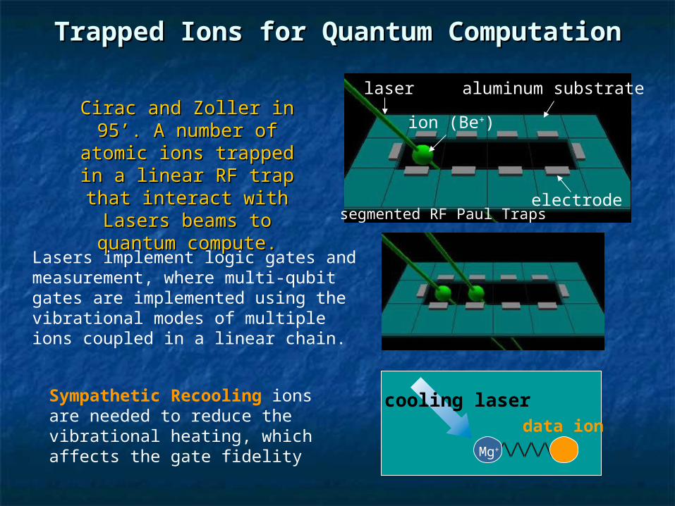
Cirac and Zoller in 95’. A Cirac and Zoller in 95’. A number of atomic ions number of atomic ions
trapped in a linear RF trap trapped in a linear RF trap that interact with Lasers that interact with Lasers
beams to quantum compute.beams to quantum compute. electrode
ion (Be+)
aluminum substratelaser
segmented RF Paul Traps

Single-Trap ExampleSingle-Trap Example
Trapped Ions for Quantum ComputationTrapped Ions for Quantum Computation
Mg+
cooling laser
Lasers implement logic gates and measurement, where multi-qubit gates are implemented using the vibrational modes of multiple ions coupled in a linear chain.
Sympathetic Recooling ions are needed to reduce the vibrational heating, which affects the gate fidelity
data ion
Cirac and Zoller in 95’. A Cirac and Zoller in 95’. A number of atomic ions number of atomic ions
trapped in a linear RF trap trapped in a linear RF trap that interact with Lasers that interact with Lasers
beams to quantum compute.beams to quantum compute. electrode
ion (Be+)
aluminum substratelaser
segmented RF Paul Traps
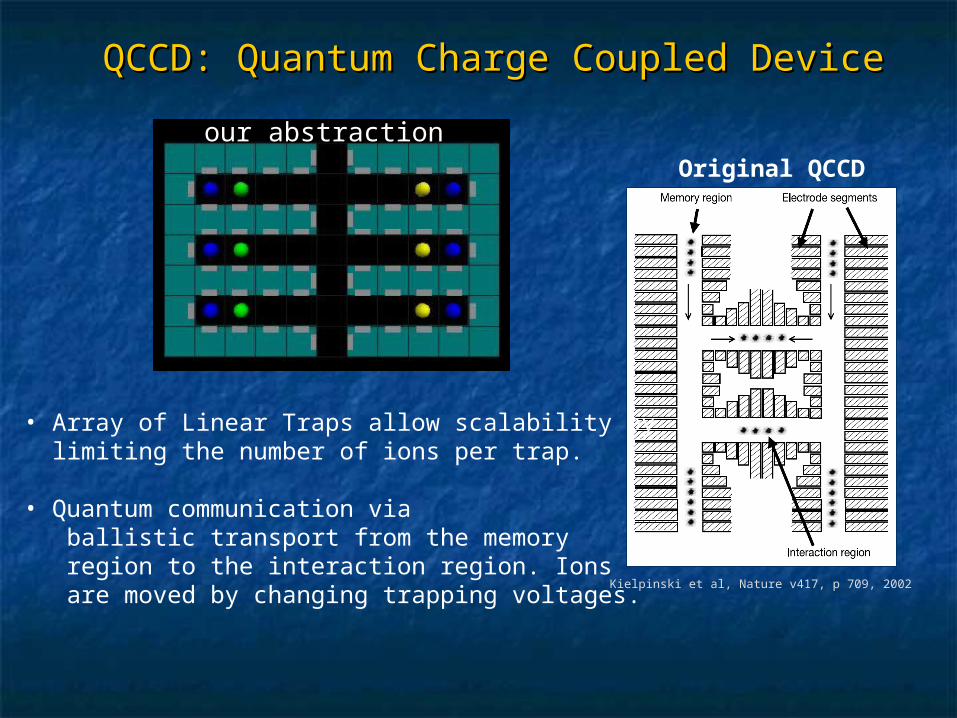
• Array of Linear Traps allow scalability by limiting the number of ions per trap.
• Quantum communication via ballistic transport from the memory region to the interaction region. Ions are moved by changing trapping voltages.
Kielpinski et al, Nature v417, p 709, 2002
QCCD: Quantum Charge Coupled DeviceQCCD: Quantum Charge Coupled Device
our abstractionour abstractionOriginal QCCD

Error-Correction ExampleError-Correction Example

Data Ions
Quantum Channels
Electrodes
Cooling Ions
QLA design trades area for communication to provide both scalability and flexibility for large-scale fault-
tolerant architectures
• Basic Blocks: Each building block consists of electrodes, the data ion, the sympathetic cooling ion, and free space around it to allow for the building of channels when the basic blocks are tiled together.
• Fault-Tolerant Structures: Large-scale fault-tolerant architectures can be built by tiling basic blocks to form logical qubits and interconnect channels between them. Qubit structures are built at design-time with computations mapped at run-time.
BasicBuilding
Block
Quantum Logic Array (QLA):Quantum Logic Array (QLA): a reconfigurable a reconfigurable microarchitecturemicroarchitecture

High Level Architecture High Level Architecture OverviewOverview
Classical Control Processors
LogicalQubit
R R
LogicalQubit
R
LogicalQubit
R
LogicalQubit
R
LogicalQubit
R
Cla
ssic
al C
on
tro
l P
roce
sso
rs
Sea of Sea of lowerlowerlevellevel
qubitsqubits
ChannelChannel
Ch
ann
elC
han
nel
RR
QLA Building TileQLA Building Tile
Average physical gate failure rates are assumed to be ~10-7 withcell size of 20 by 20 microns.

High Level ArchitectureHigh Level Architecture
~100 logical qubits per 90nm-technology Pentium 4 processor, ~100 logical qubits per 90nm-technology Pentium 4 processor, compared to 55 million classical transistors within each such P4compared to 55 million classical transistors within each such P4
Classical Control Processors
LogicalQubit
R R
LogicalQubit
R
LogicalQubit
R
LogicalQubit
R
LogicalQubit
R
Cla
ssic
al C
on
tro
l P
roce
sso
rs
49 Physical49 PhysicalIonsIons------
5292 trap5292 trapcellscells
720 μm
2940
2.11 mm2

Q1 Qk256 qubits ~ 30,000 cells
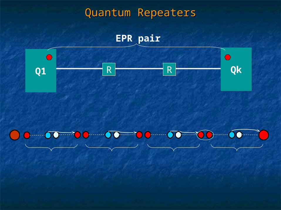
EPR
• Ballistic channels are too faulty for the data to move through at very large distances.
• We use the concept of teleportation developed by Bennet et. al. in 93, which employs entangled EPR pairs to recreate the state of an ion at the desired destination without physically moving the ion.
• The EPR pairs are purified upon arrival with the use of ancillary EPR pairs, which are constantly reinitialized to zero.
Inter-Qubit Communicationsourcesource destinationdestination

Q1 Qk
EPR pair
R R
Quantum RepeatersQuantum Repeaters
sourcesource destinationdestinationRR RR RR RR RR RR RR
Quantum RepeatersQuantum Repeaters
Q1 Qk
EPR pair
R R

Quantum RepeatersQuantum Repeaters
Q1 Qk
EPR pair
R R

Quantum RepeatersQuantum Repeaters
Q1 Qk
EPR pair
R R
Next: Channel DetailNext: Channel Detail
Teleporting the dataTeleporting the data

Communication Channel: DetailCommunication Channel: Detail
Purify
Initialize
EPR Purify
Initialize
Repeater Repeaterion

Communication Channel: DetailCommunication Channel: Detail
Purify
Initialize
EPR Purify
Initialize
Repeater Repeaterion
0.2
0.04
0.06
0.08
0.1
0.12
0.14
0.16
0.18
To
tal C
on
ne
cti
on
Tim
e d=35d=70d=100d=500d=750d=1000
d=100
Separation Distance (d)
d=350
d=350
350
700
1750
3500
7000
10500
20000
Total Communication Distance (cells)

Simple Example: Toffoli GateSimple Example: Toffoli Gate
X
Y
Z
X
Y
Z xor XY
Discovered by Toffoli in 1981, the Toffoli Gate is a controlled-controlled-NOT gate. This gate is a universal gate for reversible computation and is a special case for the three bit universal gate for quantum logic.
The NAND gate is contained within the Toffoli
X
Y
1
X
Y
X nand Y
Toffoli

Fault-Tolerant Toffoli Gate Fault-Tolerant Toffoli Gate ConstructionConstruction

Simple Example (FT Toffoli Gate)Simple Example (FT Toffoli Gate)
Dataanc
anc
A0 A1 A2
X Y Z
C0 C1 C2• Heuristic Greedy Scheduler that grabs all available bandwidth whenever it can.
• Goal is to find the minimum number of paths and bandwidth between logical qubits such that communication and computation can be overlapped.

A0 A1 A2
X Y Z
C0 C1 C2
Move A2 --> C2
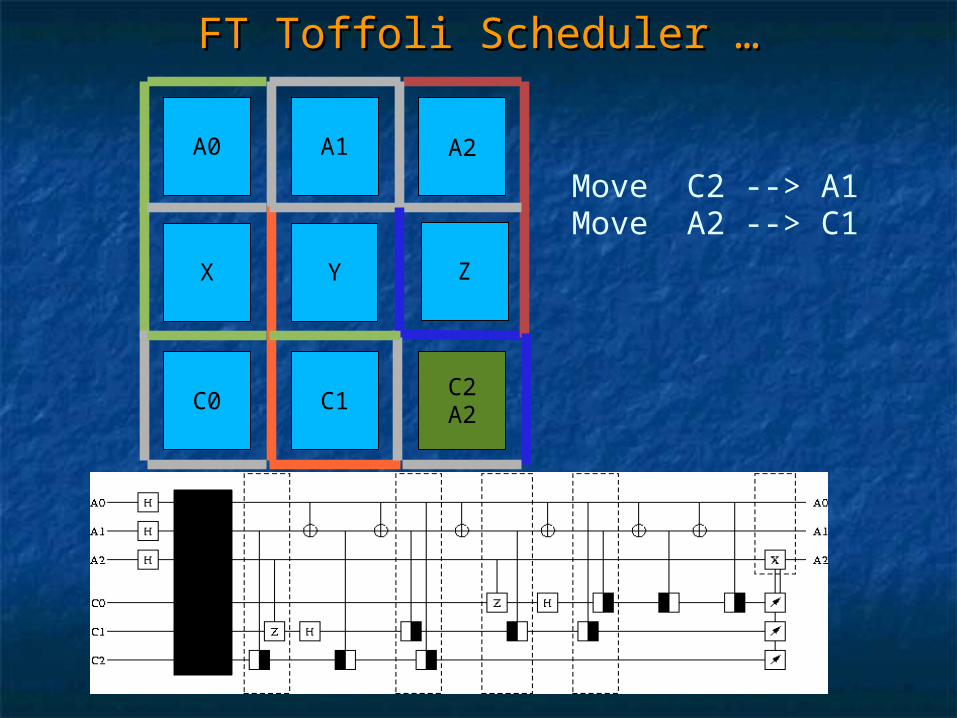
FT Toffoli Scheduler …FT Toffoli Scheduler …
A0 A1 A2
X Y Z
C0 C1C2A2
Move C2 --> A1Move A2 --> C1
FT Toffoli Scheduler …FT Toffoli Scheduler …
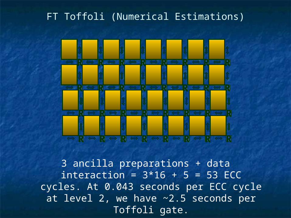
3 ancilla preparations + data interaction = 3*16 + 5 = 53 ECC cycles. At 0.043 seconds per ECC cycle at
level 2, we have ~2.5 seconds per Toffoli gate.
FT Toffoli (Numerical Estimations)
R R
R R R
R R
R
R R
R R R
R R
R
R R
R R R
R R
R
R R
R R R
R R
R

Factoring an Integer (RSA)Factoring an Integer (RSA)
ModularModularExponentiationExponentiation Maxf x mod)(
QFTQFTPeriod ofPeriod of
f(x)f(x)ClassicalClassical
Post processingPost processing
Toffoli
Toffoli
Classical Factoring: Exponential complexity. Cavallar in 2000 has demonstrated the factorization of a 512-bit number in seven calendar months on 300 fast workstations, two SGI Origin 2000 computers, and one Cray C916 Supercomputer - a process which amounts to 8400 MIPS years.
Quantum Factoring: Shor’s Algorithm proposes polynomial time, however real time estimates currently don’t exist due to the complexity of the system.
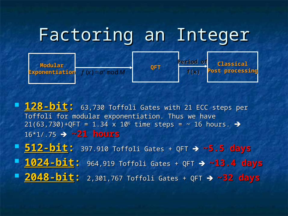
Factoring an IntegerFactoring an Integer
128-bit128-bit:: 63,730 Toffoli Gates with 21 ECC steps per Toffoli for 63,730 Toffoli Gates with 21 ECC steps per Toffoli for modular exponentiation. Thus we have 21(63,730)+QFT = 1.34 x modular exponentiation. Thus we have 21(63,730)+QFT = 1.34 x
101066 time steps = ~ 16 hours. time steps = ~ 16 hours. 16*1/.75 16*1/.75 ~21 hours~21 hours 512-bit512-bit:: 397.910 Toffoli Gates + QFT 397.910 Toffoli Gates + QFT ~5.5 days~5.5 days 1024-bit1024-bit:: 964,919 Toffoli Gates + QFT 964,919 Toffoli Gates + QFT ~13.4 days~13.4 days 2048-bit2048-bit:: 2,301,767 Toffoli Gates + QFT 2,301,767 Toffoli Gates + QFT ~32 days~32 days
ModularModularExponentiationExponentiation Maxf x mod)(
QFTQFTPeriod ofPeriod of
f(x)f(x)ClassicalClassical
Post processingPost processing
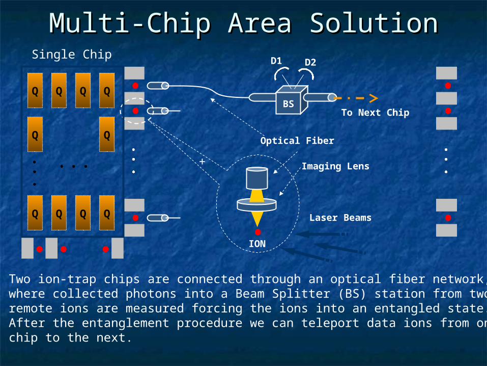
Multi-Chip Area SolutionMulti-Chip Area Solution
Q Q Q Q
Q Q Q Q
Q Q
BS
D1 D2Single Chip
Laser Beams
Optical Fiber
Imaging Lens
ION
To Next Chip
+
Two ion-trap chips are connected through an optical fiber network,where collected photons into a Beam Splitter (BS) station from tworemote ions are measured forcing the ions into an entangled state.After the entanglement procedure we can teleport data ions from onechip to the next.

Laser LimitationsLaser Limitations
Current lasers are the size of room!Current lasers are the size of room! Expect ~6-12 lasersExpect ~6-12 lasers Distribute with MEMS mirrorDistribute with MEMS mirror

MEMS Mirror ArrayMEMS Mirror Array

SIMD ControlSIMD Control
Many mirrors but few lasers -> Many mirrors but few lasers -> similar to Single Instruction Multiple similar to Single Instruction Multiple Data computersData computers
Limits to parallelism -> longer Limits to parallelism -> longer computation -> more error correction computation -> more error correction -> more control (!)-> more control (!)

Future WorkFuture Work
Scheduler to optimize execution time Scheduler to optimize execution time and number of lasersand number of lasers
Compiler to minimize data lifetimesCompiler to minimize data lifetimes Traditionally, maximal parallelism Traditionally, maximal parallelism
minimizes data lifetimes implicitly by minimizes data lifetimes implicitly by minimizing execution timeminimizing execution time
Goal: explicitly minimize data lifetime and Goal: explicitly minimize data lifetime and reduce parallelism to reduce machine sizereduce parallelism to reduce machine size

Future Work (2)Future Work (2)
Decoherence-Free SubspacesDecoherence-Free Subspaces Error correction assumes uncorrelated Error correction assumes uncorrelated
errorserrors Pair ions and use difference to represent Pair ions and use difference to represent
data -> cancels out correlated errorsdata -> cancels out correlated errors

• Qubits are phosphorus atoms in silicon
• Control with classical wires
Silicon
Device Technology
[Skinner+02]

Fundamental Constraint:Fundamental Constraint:Quantum gates require classical control lines!
• Quantum: 20 nm• Classical: 100’s of nm
( Marcus 1997 )( Nakamura, Nature 398, p. 786, ‘99 )( Yablonovitch, 1999 )

Quantum vs. Classical
[Isailovic et al ACM TACO 2003]

Architectural Implications
Communication is critical

A simple quantum wire
• Short wire constructed from swap gates– Each step requires 3 CNOT ops (swap)
• Key difference from classical:– qubits are stationary
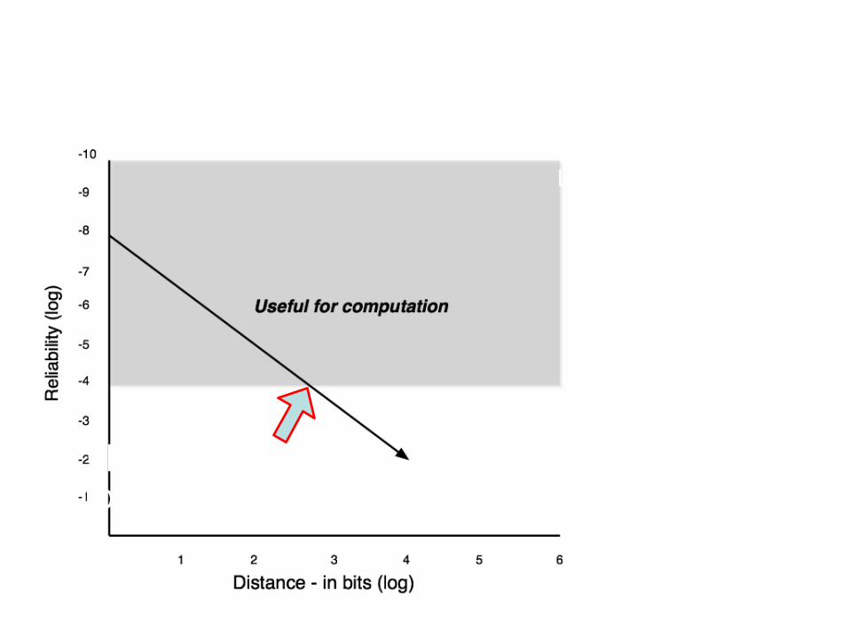
How far can you communicate?
This is ashow stopperlog(1 - C)/-λ
lat = T x D
bw = 1/T e-λD
T = time per swapD = distance (bits)λ = error rate
Latency
Bandwidth
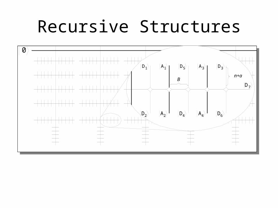
Recursive Structures0
6D4A4D2A2D
1D 1A 5D 3A 3D
7DB
n+a

Control Pulse Sequence• 2-D layout (mentioned
in Kane ’00) moves electrons in parallel– Simpler control– Better electron
separation
• Control signals still complicated!– S-gate cascade– A-gate sequence
S1S2S3
A1,A2
24
A1 A2
S1 S3
S3 S2S1
S2
e1-
e1-
e1-
e1-
e2-e2
-
e2- e2
-
. . .. . .

5-bit counter
01234
Reset
Enable
8-bit counter
Reset
1
2
3
4
5
6
7
0
D D D D D D D
D D D D D D D
S1a S1b
S1c S1d
S2a
S2b
S3a S3b
S3c S3d
S4a
S4b
TD
S1a
S1b
S1c
S1d
S1 on
S3a
S3b
S3c
S3d
S3 on
S2a
S2bS2 on
S4a
S4bS4 on
Aa
S1 on
S2 on
S3 on
S4 on
Aa
Aon
Swap control circuit
Off-on A-gate pulse subsequence (2 off, 254 on)A-gate pulse repeats 24 times
S-gate pulse cascade

Large!
• Control circuit area, ~10um2
– Aggressive process, 30nm feature size
– Minimal design
• Swap cell area, ~0.068um2
S1S2S3
A1,A2
24
A1 A2
S1 S3
S3 S2S1
S2
e1-
e1-
e1-
e1-
e2-e2
-
e2- e2
-
. . .. . .

SIMD Control• Large control circuit/small swap cell ratio = SIMD
SwapControl
A
A
S1
S3
S3
S2
S1
S2
A S3
S2
S1
S2
A S3
S2
S1
S2
A S3
S2
S1
S2
A
A
S1
S3
S3
S2
S1
S2
A S3
S2
S1
S2
A S3
S2
S1
S2
A S3
S2
S1
S2
.
.
.
.
.
.
.
.
.
.
.
.
[Isailovic et al ACM TACO 2003]

Clustering
• Recursive scheme is overkill• Don’t error correct every operation [Oskin,Chong,Chuang IEEE Computer 02]

Space Savings
Shor’s
Grover’s
p=10-6
p=10-6

Time Savings
Shor’s
Grover’s
p=10-6
p=10-6

Building Block (I)Building Block (I)• Measurement unit – computational & Bell
basis
Measure
0
Qubit to measure
Zero qubit
Classical control
Classical {0,1} outputwith probabilitydetermined by

Building Block (II)Building Block (II)• EPR generation unit
EPR
EPR Generator
0.....0Zero qubits
Classical controlQuantum outputof an EPR state
2
1100

Building Block (III)Building Block (III)• Entropy exchange unit
0 0 …
EX
P
PolarizedLight
Polarized ElectronsElectric Field
Ground

Building Block (IV)Building Block (IV)• Purification unit – error correction
Pur
Purification UnitEPR states to purify
Classical control
Purified EPR statesZero bits 0.....0
Garbage state (to Entropy Exch) NE
10
M 10

General-Purpose Architecture
• Teleportation connects comp. units• Self-refreshing memory• Parallel quantum ALU• Classical microprocessor control
• Dynamic compilation• Scheduling
Classical Microprocessor
Spin Polarized Electrons
QubitsPur
EPR
EX
Classical Bus
Quantum Bus


![Harsh Thaker, MD, PhD [email protected]](https://img.pdfslide.us/doc/110x75/620648138c2f7b173006368d/harsh-thaker-md-phd-emailprotected.jpg)