Embed Size (px)
Citation preview

Safety in Mines Research Advisory Committee
An investigation of methods to
combat mudrushes in diamond
and base metal mines
R Butcher, W Joughin and T R Stacey
SRK Consulting
February 2000
Document Number : OTH 601

Table of Contents
Page
1 Introduction .......................................................................1
2 Data collection ..................................................................2
2.1 Literature review ................................................................................32.2 Accident investigation reports ............................................................92.2.1 Case 1: Diamond Mine................................................................................102.2.2 Case 2: Diamond Mine................................................................................132.2.3 Case 3: Copper Mine...................................................................................142.2.4 Case 4: Copper Mine....................................................................................172.2.5 Case 5: Diamond Mine.................................................................................202.2.6 Boxhole and chute front accidents...............................................................23
3 Analysis of data...............................................................23
3.1 Depth of mining................................................................................233.2 Mining method..................................................................................233.3 Draw.................................................................................................263.4 Location of mudrushes and discharge volumes...............................283.5 Discharge points ..............................................................................293.5.1 Direct discharge points.................................................................................293.5.2 Indirect discharge via conduits.....................................................................303.5.3 Discharges from boxholes and chute fronts................................................303.5.4 Summary.........................................................................................................303.6 Water ...............................................................................................313.7 Properties of mud material ...............................................................323.7.1 Cave muckpile ...............................................................................................323.7.2 Backfills and tailings......................................................................................343.7.3 Mixed mud inrush materials ..........................................................................353.7.4 Mud in boxholes and passes........................................................................363.8 Blasting and seismicity.....................................................................363.9 History..............................................................................................363.10 Conclusions from the analysis .........................................................38
4 Formulation of potential mudrush mechanisms .................40
4.1 General classification of mudrushes ................................................404.1.1 External mudrushes.......................................................................................414.1.2 Internal mudrush mechanisms......................................................................434.1.3 Mixed mudrushes...........................................................................................474.1.4 Mudrushes from boxholes and chutes.........................................................47

5 Trigger mechanisms and warning signs ...........................48
5.1 Disturbance..................................................................................... 485.1.1 The excavation of slopes or stopes in mud forming materials ..................485.1.2 Possible mudrush due to tailings dam/spoil heap failure resulting from
seismicity-induced liquefaction ....................................................................495.1.3 Disturbance due to drawdown of the cave muckpile..................................505.2 Water............................................................................................... 52
6 Risk assessment.............................................................53
6.1 Fault tree methodology.................................................................... 546.2 Structure of generic fault tree.......................................................... 556.3 Risk assessment examples ............................................................. 616.4 Risk assessment summary.............................................................. 69
7 Preventative measures ...................................................69
7.1 General preventative measures ...................................................... 697.2 Mud ingress prevention through the implementation of the 3 D's
principle (Distance, Drain, Draw) .................................................... 72
8 Guidelines for the compilation of a Code of Practice for theprevention of mud inrushes..............................................76
8.1 Mudrush environment...................................................................... 778.2 Strategies for the prevention of the occurrence of .......................... 79 mudrushes ....................................................................................... 798.3 Compilation and responsibility......................................................... 81
9 Conclusions ....................................................................81
10 Recommendations...........................................................82
10.1 Classification of mines with regard to mudrushes ........................... 8210.2 Compilation of a mandatory Code of Practice for mudrush prone
mines……........................................................................................ 8310.3 Appointment of competent persons for mudrush prone mines ........ 8310.4 Annual review for mudrush prone mines ......................................... 8410.5 General precautions against mud ingress....................................... 8410.6 Recording of mudrush incidents...................................................... 84

APPENDICES
A Project proposal
B Structure of generic fault tree
C Example 1 fault tree and results of sensitivity analysis
D Example 2 fault tree and results of sensitivity analysis
E Example 3 fault tree and results of sensitivity analysis
F Example 4 fault tree and results of sensitivity analysis
G General description of the fault-event tree analysis technique

1
EXECUTIVE SUMMARY
Mudrushes as a cause of accidents in diamond and other mines were identified for specific
research, and this topic was one of the research projects gazetted for the 1998 SIMRAC
research programme. The project commenced in April 1999, with the primary output being
defined as follows:
C the assessment of mines at risk from mudrushes;
C criteria for mudrush prevention;
C a set of standards for combatting the mudrush hazard.
The ingress of mud into underground workings is a complex process requiring the simultaneous
presence of four elements before a mudrush can occur:
C mud-forming material;
C water;
C disturbance, and
C a discharge point through which the mud can enter drifts and tunnels.
The study has shown that mud can be formed internally in a muckpile or externally through the
production of tailings or the production of backfill or both. Mud in boxholes and passes can
derive from both of these sources, but also from the accumulation of fines produced during the
overall mining process. The role of mud ingress via open bench drawpoints due to slope failure
of weak geotechnical horizons is also described. In the case of caving operations, a correlation
is given between mudrushes and the occurrence of isolated draw conditions. The presence of
shale has been shown to contribute strongly to mudrushes.
The role of mine drainage in mudrush prevention has been shown from the Kimberley mines
history. A theory of water retention in cave muckpiles has been proposed. However, the
available information provided insufficient information to confirm this theory. It is possible that
data from the De Beers mines might be able to provide substantiation in the future.
2
It has been proposed that mudrushes may be prevented by the implementation of the 3 D's
principle - Distance, Drain, Draw. This principle serves to site mud-forming material away from
mines, to prevent mud formation by prevention or reduction of water ingress, and to prevent the
discharge of mud by ensuring interactive draw conditions. The implementation of this principle
eliminates or reduces mudrush triggering by limiting the effects of disturbance and water.
In most cases where mudrushes have occurred, the mine either had a history of mudrushes or
the hazard was suspected. In such cases it was found that a situation of isolated draw existed,
or that little regard was given to mine drainage or to correct mine waste disposal. Since poor
draw control and mine drainage play an important part in mudrushes, the appointment of a
competent person to be responsible for such aspects is advocated. The need for properly
designed mine drainage and draw control systems, which are regularly reviewed by external
parties, is emphasised.
It is recommended that mines in which a significant mudrush hazard exists should be classified
as mudrush prone mines and that this is enforced legally. Should a mine be classified as a
mudrush prone mine, the following measures should be implemented:
C the compilation of a mandatory code of practice for the prevention of mudrushes in
terms of guidelines which are given in the report;
C the appointment of a competent person to be responsible for mudrush control.
In mudrush prone mines, it is recommended that the competent person responsible for mudrush
control be appointed by the manager in terms of the Code of Practice for the prevention of
mudrushes. Owing to the complexity associated with mud ingress, it is recommended that, in
large scale operations, this person be in possession of an appropriate qualification as
determined by the Mining Qualifications Authority. It is recommended that an appropriate
qualification would be a tertiary qualification in one of the following disciplines: mining
engineering, geology, engineering geology, geotechnical engineering, and hydrogeology. A
person who holds a Chamber of Mines rock mechanics certificate could also qualify for this
position, provided that this person has at least 2 years of experience in that particular mining
environment. It is important that the appointed person has at least 4 years experience in the
mining industry.
3
In the case of small scale operations, the appointed person must have extensive experience in
that type of mining, and also have experience with draw control and mine drainage. For these
smaller operations, a review must be carried out on a quarterly basis by an independent
person/consultant in possession of the qualifications and experience as stated above.
All codes of practice for mudrush prone mines should be reviewed annually by an external party
to ensure independent evaluation and updated as required. This party should be in possession
of the experience and qualifications indicated above. It is important that the review consultant
has experience with mine mudrush incidents, investigations or research projects.
The incorrect design and siting of tailings dams has been seen as a major cause of inrushes.
Recommendations with regard to tailings disposal include the following. The disposal of tailings,
slimes or any other waste which could behave as a fluid should not be conducted above current
mining operations nor where, should the impoundment fail, there is a direct flow path of material
to the underground workings. The disposal of tailings should be prohibited in areas that may
undergo subsidence due to caving or failure of mine structures (eg failure of crown pillars). The
disposal of tailings, slimes or any other waste that may behave as a fluid into open cast
mines/open cuts which are situated above current operations should be forbidden. It is
important that tailings and slimes dams and their foundations are correctly designed, and the
importance of correct dam construction and management is also highlighted.
For underground mines that are extensions of open pit operations, the excavation of open pit
bench slopes in mud-forming soils or weak soft rock is critical to the prevention of mudrushes.
These slopes should be designed according to established current geotechnical best practice.
The effects of variations in rainfall and groundwater regimes, mining sequences, cave break
back zones and blasting practices should be taken into account for slope-induced mudrush
prevention purposes.
It is recommended that all mudrush incidents are included in the list of reportable incidents. They
should be reported to the Department of Minerals and Energy and recorded in the SAMRASS
database of accidents and incidents. The following information should be forwarded to the
Department of Minerals and Energy:

4
C date and time of inrush;
C location of mud rush (location indicated on a plan);
C how far the mud pushed and the quantities discharged;
C percentage extraction for the discharge drift and the drawpoint;
C mine pumping and rainfall records;
C draw control records for caving mines.
1
1 IntroductionMudrushes as a cause of accidents in diamond and other mines were identified for specific
research, and this topic was one of the research projects gazetted for the 1998 SIMRAC
research programme. The project commenced in April 1999, with the primary output being
defined as follows:
C the assessment of mines at risk from mudrushes;
C criteria for mudrush prevention;
C a set of standards for combatting the mudrush hazard.
The objective of this research is to improve awareness of the hazards posed by mudrushes,
define the factors that contribute to the mud ingresses, identify mudrush trigger factors, propose
mudrush mechanisms and developed a risk assessment procedure. Guidelines for the
compilation of a code of practice for the prevention of mudrushes were also included in the
scope of the research contract. The research has concentrated on the larger mudrush events
since these pose major hazards. However, mudrushes associated with boxholes and orepasses
have been included in the content.
The project output is directed at rock engineering personnel, draw control officials and mine
planners, who, in the course of their duties, are involved with the planning and operation of
mines at risk from mudrushes.
The contract for the research was awarded to SRK Consulting, and a copy of the approved
proposal for this contract is included for reference in Appendix A.
The main content of this report is as follows:
C review of literature;

2
C study of mudrush events contained in the literature and in accident reports, and
detailed evaluation and analysis of each event;
C from the analyses, identification of mudrush trigger facors and alternative mudrush
mechanisms;
C development of a mudrush risk assessment process, and the verification of this
process by its application to four of the mudrush events;
C determination of mudrush preventative measures and guidelines for a code of
practice from the prevention of the occurrence of mudrushes.
In the report, the mudrush events are considered from different perspectives, and there is some
repetition of material. This is deliberate, since it is considered that greater clarity of reader
understanding will result.
2 Data collectionThere were three main sources of information for the project:
C technical papers and consultants� reports;
C accident investigation reports;
C site observations and other documentation. A visit was carried out to only one
mine – O’okiep Copper mine. The main reasons for the limited extent of mine visits
was that many mines have closed or ownership has been transferred, and, in the
case of De Beers mines, access to the mines and any documents relating mudrush
incidents was denied to the project team.
The information available is reviewed in the following sections.

3
2.1 Literature review
It was surprising to find that the amount of literature regarding mine mudrushes is very limited,
despite the perception that mudrushes are a very serious problem in the mining industry. Six
well documented incidents, where mining operations had suffered major inrushes or continual
inrush problems, were identified.
Mudrushes associated with mining were first observed at De Beers and Kimberley Mines in the
late nineteenth century, with many fatalities being attributed to their occurrence. In these events,
the mudrush problem is ascribed to the breakdown of kimberlite and shale in the mine muckpile,
with the addition of rainwater via the open mine (Hunt and Daniel, 1952). Since both kimberlite
(Bartlett, 1992) and shale contain clay minerals it can be assumed that these comminuted rocks,
in combination with water, were the source of mud in the diamond mines. The sections and
plans of Dutoitspan and Wesselton Mines, presented by Hunt and Daniel (1952), indicate that
the shale originated from the upper karoo slopes, with the kimberlite being present in the
muckpile, possibly due to under-extraction of the chamber. This under-extraction was caused
by water-related ground control problems. Since chambering is a combination of shrinkage
stoping and sub-level caving (Peele, 1942), with a muckpile being formed after chambering had
been carried out on 3 to 4 levels, the possibilties of comminution of the above-mentioned rocks
existed. In addition, the muckpile would also consist of a certain percentage of dolerite,
attributed to slope failure, and this rock may not have been broken down during the mining and
caving process.
It would appear that the mudrushes were also related to active mining and drawing of the
kimberlite, since mud pushes are described as only occuring at loading places (Hunt and Daniel,
1952).
The importance of the contribution of water in mudrushes is further descibed by Hunt and Daniel
(1952). It was recognized in the latter part of the nineteenth century, during the mining at
Kimberley Mine, that the mudrush problem could be partially combatted by increasing mine
drainage with the development of water drainage tunnels. These excavations were started in
1891, with the galleries being situated in the country rock outside the perimeter of the pipe.
Water tunnels were developed were developed below the base of the shale in the Ventersdorp
lava, which is the main aquifer. These tunnels were only partially successful since they did not
prevent rain water from reaching the muckpile. Much water still still ran down from the lava/shale
contact into the muckpile.

4
The importance of drainage galleries as a method of mudrush prevention was recognized as
early as 1899 at Wesselton Mine. When underground mining began at this mine, it was thought
that a far greater mudrush risk existed, owing to the fact that mine water pumping volumes were
greater and the main shale/lava contact was deeper. The importance of the main shale aquifer,
and the need to dewater it, were recognized from the commencement of mining. Hunt and Daniel
(1952) describe the development of the first water tunnel at this mine in 1899. However, this did
not stop the occurrence of mudrushes, with 20 lives being lost to mudrushes between 1919 and
1950. In one instance 12 lives were lost. As a result of this it was decided to increase the
ground water drainage capacity of this mine by the development of a series of new tunnels.
At Dutoitspan Mine, the development of a drainage gallery system started in 1908, with the need
to prevent muckpile water ingress being recognized earlier. Two drainage tunnels were initially
developed 20m and 45m from surface, and it appears that these tunnels were relatively
successful in reducing the frequency of mudrushes.
The siting of water drainage tunnels is further described by Hunt and Daniel (1952) as being of
importance. The main criteria in this respect were:
C the location of tunnel below the main aquifer;
C situating galleries in the upper portions of the open mine, to cut off water sooner;
C development of tunnels behind the open mine break back line to prevent gallery
loss due to slope failure.
A further point of interest is that it was recognized that gallery drainage holes could become
ineffective due to calcification. If this observation is true, then water tunnel drainage holes will
require re-drilling from time to time to reduce the instances of mudrushes in the workings. The
implication is that water tunnel drainage effectiveness can decrease with time.
The water drainage tunnel systems described by Hunt and Daniel (1952) appear to have been
the first line defence in the prevention of mudrushes. A further measure included the
development of drawpoints located at the pipe contact. These excavations were used to extract
wet ground and prevent the formation of underground mud. It is also probable that this drawing
may also have increased the muckpile porosity, thus enhancing drainage.

5
Reference is made to the ability of weathered kimberlite to hang up, by acting as a plug of mud.
From this, it can be hypothesized that a weathered kimberlite mud plug could occur in the
muckpile above the workings, reducing drainage and increasing the potential for mud formation.
The need to evacuate personnel rapidly is mentioned by Hunt and Daniel (1952), and a system
of guards and air whistles was introduced at Wesselton mine in the 1950's. Such precautions
were taken to prevent underground workers from being cut off in adjacent excavations by
mudrushes.
Eden (1964) describes the inrush of large quantities of clay into the workings of open pit/open
bench slopes at Beattie Mine, Canada in 1943. The mudrush was caused by the collaspe of a
hangingwall/footwall support pillar, which lead to a failure of the rock slope and hence the failure
of the upper clay slopes. The failure mechanism of these slopes was that of earth flow due to
an increase in excess pore water pressure. The clay involved in the mudrush entered the
underground workings via an opening in the pit, and ran half a mile towards the Doncaster mine.
The owners of the mine subsequently tried to recover the mine, using a dredge to remove the
open pit clay. However, the low gold price, and further slopes failures forced this work to be
abandoned. The earth flow involved 4.6 million m3 of clay. No loss of life was recorded. This
situation differs from the experiences previously portrayed at Kimberley, where mud was formed
by the comminution of ores and country rocks. Further differences exist in that the mine was
open to surface and the mudrush affected the workings, first by filling the open pit, before flowing
into the underground mine. The trigger for the slope failure and mudrush was the failure of a
mine support pillar underground.
Similarities with the diamond mine inrushes were that clay minerals were also present in both
cases and that water also was a major factor, with seepage from a nearby lake and tailings
impoundment observed. Further, the mine had some form of warning due to the fact that smaller
slope failures had occurred in 1937 and 1942 (Eden, 1964). According to Eden (1964)
information regarding the slope profiles appears to be lacking, indicating that the clay slopes
may not have been designed. This situation is similar to that in Kimberley, where slopes in the
karoo shales were not designed in accordance with the stable angle of between 32o and 35o
(Piteau, 1970).

6
Overburden stripped during mining operations at Beattie Mine was deposited near the open pit,
possibly adding to crest loading of the clay slopes. Thus the deposition of mining wastes could
have added indirectly to the mudrush.
Jennings (1978) documents investigations relating to the failure of the No 1 slimes dam at
Bafokeng Mine on 11 November 1974, which resulted in a mudrush into the underground
workings. It was concluded that the dam wall failed with a flow slide mechanism, triggered by a
piping failure through the dam wall. Once the wall had broken, the retained slimes became fluid
and flowed into the Bafokeng shaft. The classic bottle-shaped scar associated with flow slides
was observed at the dam breach area. The major factors contributing to the failure were:
C the layering of coarse and fine particles which could have facilitated piping;
C the use of the slimes dam as a storage facility for rain water, leading to increased
pore water pressures;
C construction techniques that were applicable to gold tailings and not platinum
tailings dams.
Jennings (1978) states that the dam failure could not be attributed to mining-related subsidence,
caused by panel collapse or pillar failure in the mine workings beneath the tailings impoundment.
Midgley (1978) reports that the dam failed after a period of intense rainfall - 75mm over a two
to four hour period the night before. This again emphasises the role of water in mudrushes. A
scrutiny of the diagrams from this paper shows that the dam was situated in close proximity to
the shaft. This indicates that a potential mudrush hazard always existed.
Rudd (1978) states that the slimes dam failed very quickly, destroying mine buildings and
winding houses and flooding the shaft with slimes. 12 men lost their lives. It is estimated that
3 million m3 of slimes escaped. This indicates the hazard potential of a mudrush caused by a
slimes dam failure.
Fleischer and Sandy (1976) present the results of an investigation into an inrush of tailings into
the Mufulira Mine on the Zambian copperbelt in 1970. In this mudrush 89 people were killed
when workings were engulfed by 450000 m3 of slimes. The report also deals briefly with the
factors which led up to the mudrush. The mine used slusher block caving and open stoping
without mudrush incidents being recorded. The main tailings dam which failed was present
above the mine workings for many years. However, when the mining method changed to
7
sublevel caving, the situation changed, with higher extraction rates occurring. Although not
stated in the report, it is possible that isolated draw occurred. This resulted in the sublevel cave
drawing ground from beneath the slimes dam. This in turn led to the inrush of tailings. It was
further thought that the tailings in some parts of the dam may have been of a finer grade with
a greater moisture content and thus a greater ability to flow.
Fleischer and Sandy (1976) hypothesize that a clay layer below the dam may have acted as
flexible base and have accommodated a certain degree of ground deformation in previous years
associated with the block caving. The geotechnical investigations that were conducted on the
failed tailings dam, to stabilize the slimes in order for operations to resume, are also described.
It was found that tailings flow would not occur if moisture contents were low enough. Tailings
would consolidate if dewatered suffciently and form a dry plug with a limited mud rush potential.
Neller, Oliver and Sandy (1973) describe the associated problems attributed to the major
mudrush at Mufulira, namely the threat of mine flooding cause by the destruction of mine pump
chambers. This threat was overcome by the design of a temporary mine pumping system using
mobile submersible pumps. Additional problems mentioned by the authors were the extensive
damage to mine infastructure, and the problems of rehabilitation.
The threat of a mudrush due to tailings not only comes from slimes dam, but also can be
ascribed the failure of underground backfill. Bryant et al (1994) describe an incident that
occurred during mining at Carolusberg Deep Mine. This mine used VCR stoping to extract a
pipe-shaped copper orebody. The orebody was mined with 20m x 20m VCR stopes, which were
then post filled with a mixture of tailings, cement and blast furnace slag. The mining sequence
started with coning of the panel and then its subsequent mining by VCR blasting. The panels
were then backfilled, with mining of the adjacent panels not commencing until the backfill had
reached its 45 day compressive strength (normaly 1.5MPa). Other mining rules were that no
panel would be mined if 3 sides of the stopes consisted of under-strength fill. The paper
descibes the events that led up to the failure of the fill, the main aspects being:

8
C fill dilution of ore from the current operational stope;
C noticeable slumping of fill on the upper levels.
The authors give no reason as to why the backfill failed. The consequences of the failure were
the death of four mineworkers, and the total inundation of two production levels, the ramp system
for five levels and the main haulage.
The literature on mudrushes associated with boxholes, ore passes and chutes is almost non-
existent. Hangups in passes and boxholes, and blockages at chutes are often occurrences
which may subsequently result in mudrushes. The presence of fines, which produce “sticky”
material, promotes conditions which are favourable for the formation of hangups and blockages.
The “sticky” material is also the mud which is then available to flow in the mudrush. The sources
of the “mud” include those identified for major mudrushes, but also can be the accumulation of
fines produced by comminution of rock, and can also be backfill used in the mining operation.
Similarly, sources of water include rain water and groundwater, but more commonly would be
drilling and operation water and water from leaking or burst pipes.
These types of mudrushes usually occur as a result of bad mining and operational practices.
Unlike the major mudrushes which have been described above, in which the location of, and
potential time of occurrence of, the hazard is unknown, the potential hazard with boxholes,
passes and chutes is usually known because of the hangup, blockage or other condition. The
actual hazard is the mudrush which can occur when the chute is opened or the hangup is
cleared. To minimise the hazards in these cases, hangups and blockages should be prevented
by avoiding the tipping of oversized and foreign material, keeping the material in the pass or
boxhole moving regularly, clearing accumulations of sticky material (pagging) regularly, and
preventing water from entering passes and boxholes. In essence, these actions represent good
management of the facilities. Special chute designs and chute operating procedures have been
developed to minimise the mudrush hazard at these locations (Prins, 1995).
In summary, mudrushes have affected mining operations in South Africa for over 100 years, with
many fatalities being attributed to them. Few detailed case histories exist regarding mudrushes.
However, the reviewed literature suggests that these events are related to:
9
C comminution of rocks containing clay minerals;
C failure of slopes which comprise of clay minerals;
C failure of tailings dams associated with subsidence and/or the drawing of ore;
C liquefaction of tailings or backfill with direct flow into underground workings.
There is strong evidence that the presence of water in general, including rain and/or
groundwater, has a major influence on the occurrence of mudrushes. In this respect the paper
by Hunt and Daniel (1952) shows the efforts made to reduce the groundwater regime and hence
its effects on the occurrence of mudrushes. The experiences from Beattie Mine show that
underground workings are threatened by mudrushes due to open pit mine slope failures,
provided that connections exist between the pit and underground excavations. From the
information reported by Hunt and Daniel (1957), and that contained in the Mufulira Mine disaster
report, the inrush of mud or slimes corresponds with the drawing of ground and the change of
mining method.
2.2 Accident investigation reports
Information obtained from the SAMRASS system was initially used to identify mudrush and
drowning accidents. In this repect 56 accidents were identified in the other mines category.
However, of these, after enquiry, only 6 were found to be related to mudrushes.
The SAMRASS database itself does not contain the information required for detailed analysis.
In order to analyse the conditions pertaining to the mudrush incidents, it was necessary to
obtain the fatal accident investigation reports. Of the six reports called for detailed analysis, two
were rejected due to the fact that the accidents represented death by drowning and by
inundation due to shaft skip spillage. Ultimately, four accident investigation reports relevant to
the project, and containing sufficient information to allow detailed analysis to be carried out, were
studied.
An additional source of information was the investigation reports of investigations conducted
by independent commissions and consultants into mudrush accidents. Detailed information
existed for two cases, one of which had been entered into the SAMRASS database.
In all, five cases were available for detailed scrutiny. A description and evaluation of each of
these is given below.

10
2.2.1 Case 1: Diamond Mine
An LHD driver was killed and the LHD extensively damaged in 1992 by a mudrush whilst loading
from a sublevel cave drawpoint. The accident occurred approximately 850m below surface, and
the overburden height above the sublevel was in the region of 550m. The mud pushed some
45m along the drill drive, with in the region of 1250 m3 of mud being discharged. The mudrush
occurred in the region of 10m from the furtherest pipe contact (ie near the slot tunnel).
The inrush material consisted of about 60% mud and 40% rock. The rock fragment sizes ranged
from 100mm to as large as 4 m3. The mine had a history of mudrushes, but had enforced
mudrush precautions. These included strict draw control, mud monitoring of drawpoints, and
sublevel alarm and evacuation procedures. The management was also considering the use of
remote controlled LHD’s for drawpoint mucking. A comprehensive system of dewatering tunnels
had been developed and regular checks were made on abandoned levels for accumulations of
water. The mine was also in the process of phasing out sublevel caving in favour of block
caving. The inrush did not occur immediately after blasting.
The drawpoint where the inrush occurred was underdrawn according to the draw statistics.
Evaluation
It was stated during the enquiry that the accident occurred during sublevel caving operations
(SLC). It was further stated that the mine was in the process of phasing out SLC and re-
introducing block caving. One of the reasons for this was that it was thought that better draw
control could be maintained, with later appearance of mud. In this event, there is a parallel with
the Mufulira mudrush (Anon, 1971) since, in both instances, mudrushes occurred during SLC
operations. At Mufulira, block cave operations were conducted below the slimes dam for many
years with no mudrushes being recorded. In the Case 1 accident report, it was stated that a far
more even draw could be achieved using the block cave system. It can be concluded from these
two items of evidence, that high extraction methods such as SLC are more susceptible to
mudrushes than methods that employ a more uniform draw of ore and the muckpile above.
The crucial point appears to be draw control. In recent years sublevel caving has lost popularity
due to the low extraction and high dilution associated with the method. The main reason for the
poor performance of SLC is the difficulty of draw control. Isolated draw conditions occur
frequently, with resulting premature dilution. Two main aspects control the occurrence of
isolated draw:
11
C poor draw control, and
C layouts with poor drawpoint interaction – the drawpoints are too far apart to effect
draw zone interaction.
These problems are further compounded where ground control problems are experienced on
sublevels. In the areas experiencing ground control problems, drawpoints may be unavailable
for production, with the consequence that areas of dead draw occur. The draw control report
submitted as evidence in this accident shows that isolated draw conditions were present on the
sublevel where the accident occurred.
It was stated in the enquiry that strict draw control measures were enforced, with the decision
to load being determined by the drawpoint muckpile conditions (ie the visual presence of dilution,
water or mud). In this case, draw control was used as a method of mud inrush prevention, with
mud being associated with the amount of drawpoint extraction and dilution levels. This is
reasonable in the light of the obervations given in the literature regarding the formation of mud
above operational levels in the mine waste capping. It therefore follows that, as the percentage
of ore drawn is increased, there is an increase in the probability of occurrence of dilution or mud
reporting to the drawpoint.
In a recent invesigation undertaken by SRK in Australia, it was found that an SLC operating
under similar conditions could extract on average 120% of the fan design tonnage with only 20%
dilution occurring. This investigation also showed that dilution was first observed when more
than 60% of the fan tonnage was drawn. Certain drawpoints, however, experienced premature
dilution when only about 18% to 35% of the fan design tonnage had been extracted. An analysis
of sublevel cave line configuration in this investigation showed that premature dilution occurred
at drawpoints where there was a geological discontinuity, or where the drawpoint was situated
in a cave line configuration lag, with leading drawpoints having reached their dilution/extraction
entry levels. It was assumed that early waste ingress could be attributed to side dilution
movement - from the cave line configuration leads to the lagging areas. A scrutiny of the
accident plan shows that the drawpoint where the mudrush occurred was lagging by 14m, and
was 10m from the furthest pipe contact (geological discontinuity). The draw control report shows
an extraction of 34 % at the drawpoint where the inrush occurred. In conclusion, these facts
indicate that, with low extraction ratios, there is a potential for mud to move horizontally across
the orebody from diluted leading drawpoints to affect lagging drawpoints.
As mentioned above it was stated that the mine used strict draw contol procedures to prevent
12
the ingress of mud. This would imply that mud-like dilution would occur as a continuous layer
above the operational levels, with mud entering the drawpoints steadily once the fan dilution
extraction entry percentage had been achieved (about 60% draw). However, the draw control
report submitted as evidence shows that drawpoints on some levels were experiencing dilution
levels of between 20 and 40%, without mud ingresses being reported. This suggests that the
mud did not occur above the levels as a continuous layer. The work conducted by Bartlett
(1997) shows that the ore column and muckpile above caving operations has a variable void
ratio, with coarse fragments arching and forming cavities. Under such conditions, pockets of
mud could occupy these voids. It therefore follows that, since a mudrush is related to the
probability of drawing down a mud pocket, visual observation of drawpoint water or dilution levels
would be of little value as a warning. Dilution and water could only be taken as an indicator of
the possible existence of mud formation in the waste capping. Alternatively, the over-extraction
of drawpoints increases the probability of occurrence of a mudrush, due to the fact that greater
muckpile tonnage is extracted. The mine had recognised the role of water in the mudrush
process and had implemented a surface and underground drainage programme to control the
ingress of mud to the operations. This was probably due to the mine's history of mudrushes.
According to the statement given, the mine had suffered from this hazard since 1950, with
mudrushes being recorded from that date. The last reported inrush occurred some 3 months
earlier, on the upper sublevel, trapping a worker for 22 hours. It would therefore appear that the
incidence of mudrushes at this mine were independent of depth. This in turn may be due to the
fact that it was thought that mudrushes related to the muck pile.

13
2.2.2 Case 2: Diamond Mine
Two workers were killed when they were engulfed by a mudrush from a sublevel cave drawpoint,
and a third worker died when he fell or jumped down an ore pass. The inrush that occurred
consisted of 2630 m3 of mud. The mud pushed 150m from the drawpoint where the inrush was
said to have occurred, and filled an adjoining access tunnel. This incident occurred less than
a month after the incident described in Case 1 above, the discharge point being only
approximately 30m from that inrush point.
The inrush mud had a stiff consistency. It was dark in colour, comprising both mud and rock
fragments. These rock fragments varied in size from small lumps to large blocks of the order of
3m x 3m. The moisture content of the mud was less than 10% and the mud had an angle of
repose of 70o. The inrush did not occur immediately after blasting.
The comments regarding the mine's precautions to combat mud ingresses are similar to those
given for Case 1. However, as further protection against possible mudrushes, it was decided
to leave a stabilizing barrier of ground against the drawpoint where the previous mudrush had
occurred. The barrier consisted of choke blasted ore and was formed after the first inrush. After
the accident, to prevent a recurrence, SLC operations were halted and were replaced by vertical
retreat block caving.
Evaluation
The comments regarding the relation of SLC operations to mudrushes are similar to those made
in Case 1 above. In addition, comments relating to the draw control are similar. In this respect,
the submitted tally sheet for the previous accident (Case 1) shows that this drawpoint was 30%
overdrawn at the time of that accident, with the accident plans showing that the drift between the
two drawpoints (where the mudrushes occurred) had collapsed. A drawpoint can be defined as
being “overdrawn” when the tons extracted from that drawpoint exceed 120% of the allocated
draw column tonnage for that particular drawpoint. Since these two mudrushes occurred within
a month of each other, it is interpreted that isolated draw conditions must have existed at the
time of the Case 2 accident. An interesting observation made by the section miner was that,
before the mudrush occurred, the drawpoint ore was difficult to load (no hang-up was reported).
It may be inferred from this that compaction of the broken ore above the drawpoint could have
occurred prior to the mudrush. This, in turn, would make loading difficult due to an increase in
bulk density of the ore. A practical significance of local ore/muckpile compaction is that this
process could supply the driving force necessary to discharge a mud pocket into a drift.

14
Compaction could be caused by the collapsing of muckpile arches during drawdown. If this
observation is correct, ore and muckpile drawdown is not only responsible for mud pocket
movement, but also for supplying the necessary force for discharge into the workings. In this
connection, cognizance must be taken of the properties of the mud. It was stated that the mud
was stiff, and if the above evaluation is correct, then stiff mud could force out a plug of drawpoint
ore.
Comments regarding mine drainage, and observational control of mudrushes, are similar to
those made for Case 1. Further statements made at the enquiry indicate that mine drainage had
significantly reduced the incidences of mudrushes for 39 years.
One of the workers that was killed was said to have jumped or fallen down an orepass. Survey
plans show that the mud pushed to within 26m of the pass mouth. Statements made at the
enquiry show that the pass ventilation door was open at the time. Taking note of the stiff nature
and stated high discharge rate of the mudrush, the possibility that a significant air blast
occurred, which threw the worker down the pass, cannot be ruled out.
2.2.3 Case 3: Copper Mine
89 lives were lost when 450000 m3 of tailings flooded a large copper mine, the mudrush
occurring within ten to fifteen minutes. The mud originated from a large slimes dam which had
been in place for many years, and which was located above block cave and sublevel cave mine
workings. The mine had converted from block caving to sublevel caving, and a chimney cave
developed from the latter operation. This allowed tailings to flow into the mine through several
ingress points. The inrush mud consisted mainly of tailings, soil and clay from the dam
foundation, and ore and country rock fragments of various sizes. A surface sinkhole occurred
with 30 minutes of the accident.
Evaluation
This operation had extracted ore beneath the slimes dam for many years using block caving,
with no reported inrushes of tailings. With the change from block caving to SLC mining, the
situation changed, and the occurrence of surface sinkholes was reported. These sinkholes
indicate that isolated draw conditions, resulting from over extraction, had existed for some time.
An explanation of the reason for non-uniform drawdown is given in the evaluation of Case 1.
The sinkholes indicated on the surface plan show the possibility of over draw along the
hangingwall/ore contact. Both of these points demonstrate a correlation between the influx of
mud and the mining method and draw control. The block caving method allows for uniform

15
drawdown of reserves to be achieved more easily.
Cognizance must also be taken of the dip of the orebody at this mine. As mining progressed
down dip, caving operations were located directly underneath the tailings dam. This aspect is
further compounded by the fact that draw zones tend to incline outwards with greater overburden
depths, ie towards the tailings impoundment. In conclusion, the risk of chimney caving and
tailings draw was related to mining method, draw discipline, ore body dip and mining depth.
Concern had been raised 3 years prior to the accident about the possibility of an inrush of
tailings from the dam above. To check on this possibility, the moisture content of the tailings was
tested, and a model was built to simulate an inrush. From these investigations it was wrongly
concluded that the tailings would not flow, due to its low moisture content (20-30%), its free
draining ability and to the fact that it was considered that tailings had to be supersaturated to
flow. In addition it was observed that, with water freely draining into previous sinkholes that had
occurred in the dam, no tailings had reported underground. It is interesting to note that the
model ignored the scale of the caved materials, the dynamic similarity of the tailings, and the
continuous drawdown beneath the cave. This illustrates the difficulty involved in achieving the
required complexity of modelling of mudrushes using physical models.
In addition to the general concern raised, the following events occurred prior to the disaster:

16
C the formation of four sinkholes and depressions which subsequently filled with
tailings over an 18 month period before the inrush;
C two small sinkholes (9m in diameter) occurred on the periphery of the subsidence
area;
C six small mudrushes, which appeared at drawpoints over a period of 6 months
before the tailings inrush. Evidence submitted shows that these mudrushes
followed the retreating SLC face. It was thought that these mudrushes were
caused by the comminution and decomposition of surface soil and weathered rock
that was drawn into the workings prior to extrusion of tailings. This mud also
contained many fragments of ore and country rock, and had a low moisture
content. No tailings were seen these inrushes. It was postulated that the mud
acted as a plug, retaining the tailings. With continuous extraction, the plug was
weakened and failed under the head of tailings, thus leading to the extrusion of
mud.
C eight months before the accident, three sublevel crosscuts had to be abandoned
due to unusual pressure conditions. If this observation is correct it could indicate
an increase in muckpile point loading, due to an increase in head, possibly caused
by tailings draw. The loss of crosscuts would also increase the probability of
occurrence of isolated draw.
Immediately before the mudrush, a blasting sound was heard or a shaking was observed at
some of the upper drawpoints. Witnesses reported dust, fumes and bad air being expelled from
the main return air system. What was described was undoubtedly an air blast travelling ahead
of the mudrush. Witnesses reported that underground power and ligthing was lost and
compressed air pipes were fractured. These incidents were probably caused by the air blast or
by mud damaging or destroying mine services.
The mudrush caused destruction of almost everything in its path. During the mudrush the lower
pump station was lost, causing potential loss of the mine due to flooding. These facts illustrate
the loss of mine services that can accompany a mudrush.

17
A scrutiny of the occupations and locations of the people killed revealed:
C 62% of those killed were on operational levels;
C 66% of those killed, died when mud entered the operational levels via orepasses
or shafts;
C 46% of those killed were drift operators, with 61 % of these being LHD operators.
These figures show that level production crews, especially LHD operators are the most at risk
from mudrushes. The large proportion of people killed by mud flows that entered the levels via
orepasses and shafts, shows that not only are crews at risk from drawpoint mudrushes, but a
signficant threat exists from being engulfed or drowned from upper level inrushes via passes and
shafts. This signifies the importance of preventing mud from entering passes and shafts.
In summary, the tailings inrush was caused by chimney caving and subsidence beneath a tailings
dam. Even though cave mining had been conducted for many years in the immediate vicinity
of the dam, the progressive down dip mining resulted in draw directly beneath the dam. This
aspect was further compounded by the change in the mining method from block caving to SLC,
and by possible poor draw control. This led to isolated draw conditions and chimney caving
below the tailings impoundment. The initial effect was the drawing of soil and weathered rock,
which, by comminution, formed mud. As drawdown progressed these mud pockets formed a
plug. With continuous extraction, tailings was drawn into the muck pile, but was retained by the
mud plug. The plug was weakened by continuous drawing until it could no longer retain the
tailings and subsequently a tailings inrush occurred. The mudrush caused an air blast that
destroyed services, with the mud extensively damaging excavations and causing the loss of a
pump station. The mine was later under threat from flooding as a result.
2.2.4 Case 4: Copper Mine
Four workers were killed by a mudrush, the source of which was an adjcent backfilled VCR
stope. The operations were being conducted between two levels, 1470 and 1573 metres below
surface. Two workers that died were within 6m of a stope drawpoint on the 1470m level. The
other two workers were inundated by mud 20m from a drawpoint on the 1573m level. Although
backfill was discharged on two levels, the quantity that flowed from the lower level was sufficient
to flood the main level haulage and ramp system for 5 levels. The mud consisted of cemented
plant tailings, the total quantity being 190 000 tons (approximately 100000 m3). The mine was
in the process of filling the stope from which the backfill discharged when the inrush occurred.

18
Evaluation
At the inquiry into the accident, the backfill runaway was ascribed to the following possible
causes:
C liquefaction of the backfill due to blasting and seismicity - the mine is in a
seismically active area, with two events being recorded shortly before the mudrush.
One occurred 12 days before the event, 50km from the mine, with a magnitude of
2,3 on the Richter scale, and the second event was within twenty four hours of the
mudrush, with a magnitude of 1,2 on the Richter scale. The epicentres for both
events were similar. A review of the accident investigation report revealed that no
seismic related damage or rockmass "talking" was observed before or after the
event. In addition, the depths of the events are not given, making possible shake
out damage difficult to correlate with the events. The fact that both events were
50km away and that the mine did not have its own seismic system (signifying that
seismicity was not an issue at the mine), strongly questions this as a cause of the
backfill runaway.
Stope blasting had been suspended over 20 days before the accident. Therefore,
blasting must also be questioned as a valid possible cause of the mud rush.
19
C the presence of fissure water - the reduction of fill strength due to ground water
entering the stope cannot be ruled out, despite no major inrushes having been
seen.
C the presence of layers of alternating strength in the fill column of the adjacent
stope - the strong layers act as beams, retaining the weaker material above them.
As the head of fill on the beam increases the probability of failure of this strong
layer beam also increases. If slumping of a weaker fill layer below causes an air
gap and the beam fails, then the resulting force of the retained upper fill could
push out the lower, weaker backfill. In essence the upper fill acts as the plunger of
a pump.
The mine rock mechanics engineer stated at the inquiry that all but two fill cubes had
achieved the target strength by 30 days. It was further assumed that, because the fill
lift in the lower stope was 110m less than the design, fill strength should have been
adequate for the lift where the mudrush occurred. However, it was stated that the fill in
the upper backfilled stope was not of the correct strength. A scrutiny of backfill cube
results shows considerable variation in strength, with some results being in excess of
twice the required target strength. This variation shows that strong fill beams could have
been present. Further, only in the region of 39 test results were presented on the cube
graphs, for 60000 m3 of fill. The plant superintendent stated that 3 cubes were taken
every shift, implying that the graphs should show the results of 1250 cubes (assuming
a filling rate 18m/hour and 8 hour/shift). These facts question the fill quality control
procedures and the ability to determine fill strengths accurately.
In conclusion, the possibility of variable backfill strengths would appear reasonable as
a cause for the mudrush. Observations over fourteen days before the accident reveal
that backfill had sloughed from the fill column of the adjacent stope into the stope where
the inrush would occur. This failure has significance in that:

20
- the backfill slough could have been taken as a warning of the downward movement
of the lower stope fill column;
- the initial slough could have caused the necessary void above the stronger fill,
thus allowing the pump action to occur.
Further observation showed that the fill bulkhead failed. The standards indicate that the
bulkheads were only capable of retaining a 5.5m head of fill.
In evaluating the facts surrounding this accident, the quality and the variation in the quality of
the backfill appear to be major factors contributing to the accident. This accident shows the
importance of open stope backfill quality control. Cognizance also has to be taken of the role
of groundwater in fill strength reduction and the need for effective mine drainage.
2.2.5 Case 5: Diamond Mine
A mudrush occurred on 27 November 1995 at a small diamond mine and resulted in the loss of
20 lives. The mine had been worked intermittently since 1906, using open pit, chambering and
shrinkage stoping mining methods. The open pit contained a mixture of tailings and weathered
shale, and the mudrush was attributed to the failure of a pillar between open pit and the
underground workings, allowing inflow of the material from the pit. The pillar had been
weakened by the excavation of a ventilation shaft, the removal of ground below the pillar by
drawing, and by the weight of the weathered material above. As drawing increased, the pillar
failed, resulting in the mudrush.
Evaluation
Draw control features as an aspect which contributed to the inundation. Records show that
unrestricted drawing was being carried out beneath the area of the pit where subsidence
occurred, and where the mudrush is said to have occurred. A scrutiny of the plans shows that
the extracted ground may have been removed from contact drawpoints, and thus making
chimney caving possible through to the waste capping. This may have been compounded by
the narrow geometry of the pipe, making funnelling possible.

21
One of the major drawbacks with chambering and shrinkage stoping is the number of drawpoints
that must be controlled. This, together with a lack of draw control procedures at the mine, made
over-extraction possible. A further problem with these methods is the reduced extraction ratio
compared with other kimberlite mining methods. The significance of this is that kimberlite pillars
could have been left behind. These pillars could have provided a source of mud material due
to weathering.
In addition, over the years, mud material was further derived from the progressive weathering
of the shale country rock and the placement of tailings in the open pit. It should further be noted
that tailings were deliberately dumped into the open pit to prevent the inflow of rain water into
the underground workings. Under drawdown of the muckpile, the above materials would have
been broken down to release clay minerals, and thus mud layers or pockets could have been
formed. Owing to the mixture of muckpile material, mud could have accumulated in pockets or
layers. These pockets formed by comminuted shale, tailings and kimberlite collecting in muckpile
voids as the muckpile was drawn down. Evidence of the existence of large muckpile voids is
given by the fact that little subsidence movement was observed at the base of the old open pit.
This lack of subsidence indicates a possible hang up of material in the muckpile. Under such
circumstances, coarse material tends to arch, preventing ore drawdown. In the areas above and
below the hang-up, a higher muckpile void ratio normally exists, where mud pockets or layers
can accumulate. The documents available for this case indicate that a crown pillar, or remnant
pillars, may have been left between the open pit and the underground workings, with the sudden
inrush of material being attributed to the failure of these pillars. However, owing to the nature
of the kimberlite, it is doubtful whether these pillars could remain intact. A more realistic scenario
would be that muckpile arches were formed between crown pillar remnants and the orebody
contact. The hang-up of the muckpile is normally associated with over drawing and the removal
of fines from the draw column. The creation of arches in the shrink also gives the driving force
necessary to push the mud pockets out into the workings. This occurs with the collapse of the
arches and the resulting rapid compaction of the muckpile. The subsidence or failure that
occurred at the bottom of the open pit indicates that this could have happened. The air blast
could possibly be attributed to muckpile compaction and the discharge of mud along the
underground workings.
With regard to mine drainage, it is clear that both rain and groundwater played a role in the
mudrush. The mine was historically described as wet. However, the evidence suggests that it
was the gradual accumulation of water in the mine more that a sudden inrush of ground or rain
water that contributed to the mudrush. Hydrogeological information indicates that groundwater
inflows into the mine were constant and that the mine’s dewatering system could adequately
22
manage with these ingresses. It appears that a water balance for the mine did not exist and that
pumping records were inaccurately kept. Pumping records show values ranging from 80000 to
190000 litres per hour. The range discrepancy may be attributed to inaccurate records or
possibly could indicate that water was being retained in the muckpile, with periodic discharge
occurring. If this is correct, it could be hypothesized that, as muckpile drawdown continued, mud
pockets or layers were formed in the shrink pile voids, which reduced the permeability of the
muckpile, and hence the mine pumping rates decreased. When minor mudrushes occurred, as
was indicated in the documentation, then muckpile permeability was restored and pumping rates
increased.
The surface water drainage system appears to have been inadequate and pumps and drainage
trenches were not maintained or emplaced. This had the effect that rain and surface water
runoff accumulated in the open pit, and also that runoff and seepage from a vlei and tailings
impoundment could possibly enter the workings. If the experience from the Kimberley mines, as
mentioned earlier, is taken into account, then the drainage measures employed at this mine were
inadequate for mudrush control.
Mention must be made of the history of mudrushes at this mine. For a period of 30 years,
concerns were expressed by the Department of Minerals and Energy and independent
consultants about the possibility of mudrushes occurring at this mine. On one occasion
inspectors observed evidence of mud discharge from a drawpoint. In the 18 months prior to the
major inrush, concern was raised regarding the inrush potential by the Department of Minerals
and Energy. These concerns were based on the following factors:
C the accumulation of weathered kimberlite, blue ground and country rock in the
muckpile;
C the drawing of ore from the muckpile, which could lead to void collapse and mud
ingress;
C the presence of water in the open pit;
C the lack of open cut surface subsidence.

23
2.2.6 Boxhole and chute front accidents
Information obtained from the SAMRASS database shows that, for “other mines” no mudrush
accidents occurred at boxhole, chute or orepass locations during the past 5 year period.
3 Analysis of dataAn assessment of the literature and accident information has been given in the sections above.
Based on this information, the aim of this chapter is to analyse the data to investigate possible
correlations between the various mudrush events.
3.1 Depth of mining
The mudrush incidents analysed occurred over a wide range of operating depths, from surface
open bench type mines (Owen and Guest, 1994), chamber workings at depths in the region of
150m below surface, sub level cave workings at depths of 850m below surface and VCR stopes
1450m below surface. It may be concluded that there is no direct correlation between
occurrence of mudrushes and mining depth.
With regard to muckpile overburden height, which is relevant only to caving or chambering
operations, the muckpile heights on the two sublevel caving operations at which inrushes
occurred were from 500 to 550 m. In the case of chamber workings in which mudrushes
occurred, overburden (ore muckpile and waste capping above) heights were in the range of 100
to 150m. A correlation between muckpile height and occurrence of mudrushes therefore does
not appear likely. However, the importance of the muckpile height is that it may provide the
necessary head to force mud pockets from draw columns into the workings. This would occur
during muckpile arch collapse and draw column compaction. In addition, the height of the
muckpile is important in the comminution of ore fragments and wastes to release mud forming
minerals. From the cases and accidents studied, it would appear that overburden heights in
excess of 100m provide the necessary height to allow sufficient comminution in the draw column
and sufficient head to generate the driving force for mudrushes.
3.2 Mining method
In the consideration of mudrush potential for different mining methods, the information obtained
24
has shown that mud ingress occurs in the following manners:
C direct flow of tailings or slope materials via shafts, adits or open bench drawpoints
into underground workings;
C direct draw of internal and/or external mud pockets or layers during caving and
chambering operations;
C direct flow of mud from backfilled stopes
This indicates that any operations where there is a potential direct flow path for tailings to open
drawpoints, shafts or adits are at risk from mudrushes. This was illustrated in the case of the
Bafokeng accident, with the failure of a slimes dam and direct flow of tailings into a shaft. This
mudrush event emphasises that correct siting of tailings dams (and other waste or spoil dumps
which are a source of mud) is of major importance for the prevention of mudrushes.
The Beattie Mine inrush illustrates the risk which surface open benching operations face from
slope failure. In this case the clay slope slough was triggered by the failure of the open pit
support pillar, and a massive inrush of clay to the workings via open drawpoints resulted.
Analysis of this event shows that a mining method, which involves the creation of slopes in soil
or weathered geological horizons and underground drawpoints open to the surface, is at risk
from mud ingresses. The diamond mining operations at Finsch and Koffiefontein, and also some
of the smaller diamond mines, may fall into this category. The Beattie case emphasises the
need for correct slope design in the prevention of mudrushes.
Of the five accident investigations reviewed, three occurred in sublevel caving operations. It may
therefore be concluded that the risk of mudrushes is greater with sublevel caving mines than with
any other mining method.
The main reasons for mudrushes, determined from the review of literature and accident
documentation are:
25
C greater non-uniform rates of draw, resulting in increased localised subsidence
associated with mining. This could threaten the stability of tailings dams or other
bodies of mud material or water and result in the ingress of water, mud material or
tailings into the mine;
C poor draw control and the frequency of isolated draw conditions.
In Case 1 the mine was in the process of converting from SLC to block caving because it was
thought that better draw control could be achieved with block caving. It would appear that cave
mining mudrushes are related to the ability to control the draw. In methods such as SLC or
chambering, many drawpoints exist, as a result of which loss of control on draw occurs easily.
Further, because these mining methods are top down systems, the waste capping is closer to
operating levels than with a block cave - block caves can have ore block heights in excess of
100m. Therefore, when considering the susceptibility of a mining method to mudrushes, the
height interval between the drawhorizon and the waste capping is important. In essence the
greater the distance to the waste capping, the less the risk of a mudrush since the possibility of
drawing into the waste capping is reduced.
Mining methods in which large tunnels have to be developed in weak ore bodies mean that it is
expensive and difficult to achieve and maintain drift stability. In both Cases 1 and 2, SLC levels
had suffered ground control problems. Under such conditions, there is a lack of drawpoint
availability and, if production calls are not reduced, over extraction from working drawpoints can
occur. In this respect, ensuring the suitability of the mining method for the ground conditions is
an indirect factor in mudrush prevention. In methods such as SLC large tunnels are sometimes
developed in weak, cavable ore bodies, which results in drift stability problems. This could be
construed as poor mine design.
A further factor associated with cave mining is the underestimation of zones of surface
subsidence. In the case of Mufulira, this problem was compounded by the fact that, as mining
proceeded down dip, the angle of draw projected directly under the tailings dam, resulting in
tailings draw. It is therefore important that surface subsidence areas are accurately assessed
in relation to orebody geometry when considering a mining method�s susceptibility to
mudrushes. The Mufulira inrush demonstrates that all structures that contain potential mud
materials should be sited beyond zones of potential surface subsidence and tensional damage.
In the case of mudrushes from backfilled stopes, the case reviewed indicates the importance of

26
backfill quality control in mining method selection. The conclusion is that large scale backfilling
should not be used if fill quality cannot be assured. In addition, it illustrated that stope bulkheads
are incapable of retaining massive inrushes of backfill.
From all of the available information, it was found that no mudrushes occurred in areas where
active mining was not taking place. This observation is of considerable importance since the
conclusion is that, for a mudrushes to occur, mining must be taking place - in essence, the mud
material must be disturbed.
3.3 Draw
Consideration of the state of draw is only applicable in cases in which cave mining was taking
place. The available information shows that, in all cases of cave mining mudrushes, a
correlation existed with the state of draw. In the case of SLC operations, non-interactive draw
was occurring on levels where mud entered into the workings. This can be attributed to:
C the loss of a drawpoint due to ground control problems, resulting in drawpoints
being pulled in isolation;
C poor draw control practices resulting in over draw and the migration of the waste
cap, tailings and mud pockets onto the production level.
In the case of Mufulira, chimney caves through to surface indicate high rates of draw from the
ore body contact. In Cases 1 and 2, isolated draw conditions existed on the SLC level where the
mud ingresses occurred. These conditions took the form of over drawing, lagging drawpoints
in the cave line sequence and drawpoint loss. In these two cases it was stated that strict draw
control was implemented to prevent the occurrence of mudrushes. As stated previously, there
must have been an historical correlation between draw and the occurrences of mud. Taking
cognizance of the observation of Hunt and Daniels (1952) that mud was formed in the pit and
drawn into the waste cap, it is logical to assume that mud could be related to dilution and hence
draw. In essence, over drawing produces mudrushes due to the drawing of dilution containing
mud. However, in Case 1, draw control reports indicate 20% to 40% drawpoint dilution levels,
from which it can be interpreted that drawpoints had possibly been extracted to 120% to 140%,
with no mud being reported. This suggests that the mud did not occur above the levels as a
continuous layer within the waste capping. This is possibly confirmed by the work conducted by
Bartlett (1997), which showed that the ore column and muckpile above caving operations has
a variable void ratio, with coarse fragments arching and forming cavities. Under such conditions,
27
pockets of mud could occupy these cavities.
Therefore, even though the probability of mud ingresses increases with isolated draw and over
extraction from a drawpoint, owing to the fact that mud is contained in pockets rather than layers,
overdrawing does not necessarily mean that a mudrush will occur at that drawpoint. However,
the occurrence of sideways movement of mud pockets cannot be discounted based on the
evidence given in Case 1. In this case a mudrush occurred in a cave line lagging drawpoint
which was less than 50% extracted.
In the Mufulira case where over extraction resulted in the drawing of slimes from a tailing dam,
mud ingress can be thought of as the drawdown of a continuous layer of dilution material, not
as pockets. This conclusion was reached due to the fact that tailings ingress was from multiple
discharge points and levels following the retreating SLC faces. Therefore, mud reported to the
drawpoints in the same way as dilution does.
It is concluded that, when mud is formed in the cave muckpile, it takes the form of pockets in
cave voids. In the case where the mud originates from an external source it acts as a layer of
dilution.
The correlation of mud ingress with SLC mining relates to the difficulty in maintaining a uniform
drawdown of caved material. The reasons for this have been given in the previous sections.
In the case of block caving, draw control is easier to implement and is facilitated by the bottom-
up nature of the mining method. This makes dilution problems easier to correct due to the
distance from the waste capping. However, as the ore block is drawn down and the waste
capping nears the draw horizon, the same problems experienced with an SLC may occur. In
essence, block caving allows for uniform draw to be achieved and for the occurrence of chimney
caving to be reduced. It delays the problems of potential mud draw until near the end of the life
of the cave.

28
In Case 5 unrestricted draw was occurring along the orebody contact, which led to possible
chimney caving into the waste cap and mud ingress. The lack of surface subsidence in the open
pit again indicates poor draw control practice, which results in muckpile hang-ups. In this case
not only was unrestricted draw being practised, but standard draw control procedures did not
exist.
In conclusion, a strong correlation exists between poor or non-existent draw control and mining
methods in which the occurrence of isolated draw conditions can easily occur (SLC). There is
some evidence to allow the opinion that mud occurrences can be controlled more easily using
block caving, owing to the bottom-up mining method, and to the ease of achieving uniform ore
drawdown. However, once the waste capping is in close proximity to the block cave draw
horizon, the mudrush risk increases.
3.4 Location of mudrushes and discharge volumes
Table 1 shows the location of mudrushes within the workings and the relative volumes of mud
discharged.
Table 1 Locations of mudrushes and discharge volumes
Case Mining
method
Mud volume Distance
Pushed
Location
1 SLC 1250m3 45m 30m from contact
2 SLC 2630m3 150m 40m from contact
3 SLC 450,000m3 +/-1490m 40m from contact
4 VCR 103000m3 +/- 700m +/-15m from contact
An analysis of the accident investigation plans shows that most of the mudrushes occurred near
the orebody contacts. In the case of the SLC mining this could be due to overdrawing, which
was indicated in the Mufulira case by the presence of surface sinkholes near the footwall and
hangingwall contacts. This could be attributed to the over extraction of drawpoints near the
contact slot, to ensure that sufficient void existed for ring blasting. Alternatively, it could indicate
footwall self caving due to poor contact conditions. The inrushes examined in Cases 1 and 2
occurred during the mining of a diamond pipe. In this respect, the presence of wetter ground
conditions in the vicinity of the pipe contact, and the fact that shale may preferentially collect
(after sloughing from the open mine) near the contact could have a bearing on the frequency
29
of mud rushes near the contact.
An examination of the above table shows that there is a significant difference between the
volumes of mud discharged in Cases 1 and 2, and in Cases 3 and 4. The main reason for this
is that the material discharged in Cases 1 and 2 consisted of mud that was formed during the
break down of kimberlite and shale during cave drawdown. This mud had a stiff consistency and
was reported to have a low moisture content. Obviously, being stiffer, the distances that the mud
pushed would be less. It can be concluded that the mud discharged during these incidences
probably occurred as pockets in the muckpile voids and, as a result, discharge volumes would
be limited to the size of pocket being drawn.
In contrast, Cases 3 and 4 inrushes were attributed to tailings from a dam above an SLC
operation and failure of backfill from a VCR stope. In these instances the tailings had a high
moisture content, and, due to the nature of the sources, discharge volumes were only limited
by the capacity of the backfilled stope or the porosity of the muckpile below the dam. It was
further evident that tailings inrushes have more extensive effects effects that mud pocket
inrushes, owing to the volumes of materials that can be drawn.
In conclusion, from the limited data available, there is a correlation between mudrush occurrence
and the proximity of mining to the orebody contacts. The discharge volumes and pushed
distances are greater from tailings inrushes.
3.5 Discharge points
3.5.1 Direct discharge points
A review of all the accident data shows that the mud entered the workings in all but one case via
open bench or underground drawpoints. A scrutiny of accident investigation plans shows that
all drawpoints had dimensions in the region of 4m x 4m, with discharge volumes ranging from
1253m3 to 103000m3. In Case 1, it was stated that the mine was in the process of converting
from sublevel caving to block caving since it was considered that better control of mudrushes
could be maintained not only by improved draw control, but also because the block cave system
would have smaller drawpoint dimensions (of the order of 1m in diameter), through which a
lesser volume of mud (per unit time) could discharge. From the data reviewed, there is no
information to corroborate the above statement. However, the mine in Case 1 had a history of
using block caving under mudrush conditions, so it would be reasonable to conclude that this
statement is based on some historical observation (this assumption is based on the descriptions
30
of block caving at Kimberley mines by Gallagher and Loftus (1960) and Hartley (1981), where
there was a history of mud ingress from 1891). Furthermore, it is logical to assume that, if the
discharge point dimensions are smaller, then the volumetric rate of mud discharges must be
reduced. Therefore, in a mudrush prone environment, it may be concluded that the use of
smaller drawpoints may assist in reducing the mudrush hazard.
3.5.2 Indirect discharge via conduits
The accident report for Case 4 recorded that 66% of those killed died when mud entered the
operation levels via orepasses or shafts from upper inrush levels. At Bafokeng Mine,
underground workers were killed when slimes entered the workings via the shaft. From these
cases it is apparent that not only are workers at risk from inundation from drawpoints, but face
mud inrush hazards from secondary excavations (those excavations through which mud can
travel to other areas of the mine workings). The significance of this is that high priority must be
given to securing such mud transport excavations from inrushes if the severity of the mud push
is to be controlled.
3.5.3 Discharges from boxholes and chute fronts
The volume of material that can discharge from a box or chute front depends on the “strage
capacity” of the boxhole or pass. Many chutes are still manually operated, with the operator in
close proximity to the chute. Others are pneumatically operated, and the operator can be
remote from the chute. With single door chutes, which are commonly used, in the event of a
mudrush, it is generally not possible to close the chute since it will most probably be blocked by
larger rock fragments. Therefore, once such a mudrush starts, it is likely that all the “stored”
mud will flow, representing a hazard to personnel in the excavation below. The accumulation of
the mud in the excavation also represents a hazard in the general sense since it hinders access,
will result in slippery conditions and will have to be removed.
3.5.4 Summary
In summary, discharge points can be thought of in three categories:
C direct mud discharge points (ie drawpoints where mud enters directly from the
stope or cave);

31
C mud transport excavations (ie excavations where mud travels to other workings
from the direct discharge point, such as passes, shafts, ramps, boxholes etc);
C discharge of mud directly from box fronts and chute fronts at boxholes and
orepasses.
3.6 Water
In all data studied it was considered that the influx of rain or groundwater contributed to the
inrushes.
In Cases 1 and 2, complex systems of dewatering galleries were installed to reduce the mudrush
problem. Further, greater efforts were made to identify water bearing geological structures and
horizons, and to reduce inflows from these discontinuities. Underground sumps and pumps were
installed, and contact dewatering and drawing were implemented to prevent the migration of
water to the centre of the pipe. In the case of the most recent diamond mine inrushes, it was
stated that the mine took the visual presence of water in the drawpoint mouth as a potential sign
of mudrushes. The inrush at the small diamond mine described in Case 5 was also partly
ascribed to the presence of water and the lack of adequate drainage measures around the open
pit. As in the other diamond mines mentioned by Hunt and Daniel (1952), this mine also had a
history of water problems.
The importance of mine pumping and the need to dewater the muckpile are described both in
the abovementioned paper and in the Case 5 accident investigation documents. Hunt and
Daniel stated that the quantities of water pumped from the Kimberley mines are insignificant
compared with other operations. However, due to the weathering associated with kimberlite, any
inflows could be problematic. The dewatering capability of the mine was investigated during the
Case 5 accident, since, as described previously, concern was raised about the accuracy with
which pumping records were kept (the large range of results). However, the range in pumping
results could indicate possible water retention in the mine's muckpile. This could happen if mud
pockets or layers block muckpile voids, thus reducing permeability and drainage. If a mud
pocket is drawn then the muckpile permeability and pumping would increase. Even though this
hypothesis is based on one case, it emphasises the need for mudrush prone mines to keep
accurate pumping records to ensure that adequate muckpile drainage is being achieved. It was
also considered that it was the accumulation of groundwater over the years rather than one
single event that contributed to the mudrush.
In the case of Mufulira inrush, the high moisture content of the tailings and the location of the
32
dam in a low lying area are cited as facts contributing to the inrush. Due to the rate of deposition
of slimes and the climate, large pools of water were sometimes present on top of the dam. It was
thought that this water would percolate downwards, thus leaving dry tailings. In effect, high dam
moisture levels fluidized the tailings allowing it to flow easily into the muckpile during drawdown.
At Bafokeng Mine, poor dam design and use of the slimes impoundment as a rain water storage
facility resulted in dam failure and mudrushing. In essence, the mudrush can be attributed to
poor water management. In Case 4, the high moisture content and poor quality of the backfill
was the main cause of the mud influx from an adjacent stope.
In addition to rain water and groundwater as sources for water in mudrush events, with regard
to boxhole mudrushes, water more commonly originates from drilling water, drainage water from
hydraulically placed backfill, and burst and leaking pipes. In all of these cases water can be
controlled. Its uncontrolled ingress into boxholes and passes, and the lack of controlled
drainage therefrom, is a result of poor mining practice.
In summary, water plays two roles in mudrushes:
C it contributes to the formation of mud from comminuted ores and wastes due to
weathering in the cave muckpile and due to interaction with fines;
C it increases pore water pressures and allows fluidization of fines, tailings and
backfills.
It is important to distinguish between these two roles as the amelioration measures will differ. In
this respect the control of tailings and backfill mudrushes relies heavily on placed material quality
and dam management, whereas prevention of cave muckpile type inrushes is focussed on mine
drainage. Prevention of boxhole type mudrushes requires more disciplined mining practice.
3.7 Properties of mud material
Unfortunately it was not possible to obtain samples of mud for analysis and geotechnical testing.
Therefore, information on mud properties had to be obtained from the documents analysed.
The materials which form mine mudrushes can be divided into three groups. These are cave
muckpile, including ores and waste rock; backfills and tailings; and mixed mud inrush materials.
Each of these will be dealt with in turn.
3.7.1 Cave muckpile
33
The description of the characteristics of mud from the kimberlite muckpile mudrushes, described
in the literature and the accident reports (Cases 1 and 2 in Section 2 above), provided the
following information.
Mud properties: the inrush material had a stiff consistency and consisted of both mud and rock.
The rock fragments ranged from about 300mm to 3m in size. 60% of the material was mud and
about 40% was waste rock. The moisture content of the mud was less than 10% and the
density was 2.61 tonnes/m3. When the mud was stationary it had an angle of repose of 70o.
Mud origin and composition: from the above it can be seen that waste rock comprises 40% of
the discharged material. Reviewing the geological section of the various diamond mines in the
areas where the inrushes occurred, it can be seen that the karoo dolerite, upper dwyka shale,
dwyka tilllite, Ventersdorp lava, quartzite and basement granite gneiss could possibly form the
rock fragments. Photographs of South African diamond mining operations show that the slopes
of the open holes are stable in the lower Ventersdop lava, quartzite and granite gneiss, with
angles in the region of 80o. It can therefore be concluded that limited amounts of this material
would be expected as mud rock fragments. The photographs further reveal that the upper
slopes are unstable due to the weathering of the shale and subsequent dolerite toppling. The
paper by Hunt and Daniel (1952) states that it is the accumulation of weathered shale in the
base of the open mine that contributes mainly to the mudrush problem. It can therefore be
concluded that the waste rock components in the mud must consist largely of dolerite, since most
of the shale will break down during the drawing process.
With regard to the 60% mud in the discharged material, two possible sources exist - the
kimberlites, which contain clay minerals, and the shale. The tuffisitic kimberlite breccia type of
kimberlite contains the highest proportions of clay minerals. Again, Hunt and Daniel (1952) refer
to the ability of this rock type to break down under the action of weathering in the base of the
open mine.
The question remains as to which of the two rock types contributes most to the muckpile mud.
Julin and Tobie (1973) state that the diamondiferous block caves have extraction percentages
in the region of 80%. It is therefore evident that the remaining 20% of the kimberlite may be
present in the muckpile. No documentation was found relating to mudrushes in Premier diamond
mine. This information would be of interest since shale does not feature in the country rock
horizons, but significant zones of tuffisitic kimberlite breccia do exist. In Case 5, upper weak
shale horizons were present and significant quantities of shale were found in the mud samples
analysed.

34
If it is assumed, from the above, that 20% of the discharged material consists of kimberlite, then
48% (60% of 80%) of the mud must be shale. It may be concluded that the main mud forming
material is probably shale and therefore any cave mine which has shale country rock horizons
is likely to be at risk from mudrushes.
Ability to flow: the density of the mud was determined at 2.61 tonnes/m3, which is not a flowable
material. The implication of this is that mud pockets, when formed, do not flow readily through
the mud pile voids, but have to be drawn or forced out of the draw column. This could occur
during muckpile arch collapse associated with high rates of isolated draw and a large muckpile
height.
3.7.2 Backfills and tailings
The mud properties determined from accident investigation reports indicate that the Case 4
backfill runaway can be attributed to under strength fill and the lack of appreciation of the
mudrush potential from such poor quality fills. The backfill from the stope which failed was 18%
below the required target strength. However, due to the fact that a small lift was being placed,
and the fact that a factor of safety of 1.4 was applied in the backfill strength design, the low
strengths were not seen to be a problem. There also seemed to have been a lack of
appreciation as to why a factor of safety is applied (to ensure that design requirements are
always achieved despite system or process variability). An aspect mentioned in Section 2 is the
limited number of tests conducted to determine the fill strength. It can be deduced that strength
testing was not representative. In addition, data showed considerable variation, indicating that
a consistent product was not being produced by the plant. Fill strength tests conducted by the
Chamber of Mines Research Organisation on samples from adjacent stopes confirmed that
strengths did not meet the specification.
In the case of the Mufulira Mine, 96% of the tailings deposited in the dam were unclassified, and,
in some instances, deposition involved only 50% solids by weight. It was also reported 3 years
before the mudrush that the tailings were waterlogged and unstable. It was further stated that
the moisture content of the tailings was in the region of 20% to 30%, but it was considered that
tailings would only flow in a supersaturated state. However, experience with dam engineering
would seem to disprove this. Again this inrush shows the importance of correct material design
to ensure that mining wastes are not in a state that can flow into subsidence or cave areas.
The inflow of slimes into the Bafokeng shaft is a further case of incorrect mining waste disposal.
Jennings (1978) showed that the gradings of slimes materials were unsuitable for dam

35
construction owing to the difference between the coarse and fine fractions and the susceptibility
of this material to liquefaction. This situation arose as a result of the application of gold mine
dam construction techniques to platinum tailings. The situation was further compounded by the
fact that the building of a cross wall destroyed the dam beach. This resulted in the fine tailings
fraction being washed into pools near the wall instead of into the middle of the dam.
In summary, the inflow of tailings and backfills are mainly due to poor dam design and
construction practices and failure of quality control procedures to deliver tailings and backfills
to meet design specifications.
3.7.3 Mixed mud inrush materials
The analysis of Cases 3 and 5 has shown that mudrushes can involve a mixture of the materials
described above. In Case 3, several mudrushes consisting of soil and ore fragments, with a low
moisture content, preceded the main tailings inrush. The initial inrush material appears to be
similar in nature to the muckpile waste and ore described in Section 3.6.1 above. This type of
mud could have been formed by the drawing of the clay horizon below the dam and the muckpile
ore and wastes. The fact that this mud did not occur in every drawpoint indicates that it probably
occurred in pockets.
In Case 5 the analysis indicated that the mud was formed from three main sources:
C the comminution of shale, which had sloughed from the sidewalls;
C the deposition of tailings in the open pit;
C remnant kimberlite.
The sampling conducted during the accident investigation identified the shales and the tailings.
It did not positively identify kimberlite ore, but stated that some form of kimberlite contamination
was present. The consequences of this are that the kimberlite ore was either highly weathered
or was present only in insignificant amounts. However, if cognizance is taken of the information
in Section 3.6.1 above, kimberlite does not have to be present in large quantities to be
problematic. However, again a correlation between mudrushes and shale is indicated.
The main consequence of a mixture of mud forming materials is that mud can take the form of
pockets or layers, or a combination of both, within the muckpile. Therefore, the possibility of
using control measures for safety as a means of mudrush prevention becomes difficult, owing

36
to the variable nature of the mud material.
3.7.4 Mud in boxholes and passes
The sources of mud in boxholes and passes includes all of the above. Comminution of all rock
materials (not only the common mud forming rock types), during all mining processes produces
fines which can accumulate in boxholes and passes. This “sticky” material, which is also referred
to as pagging or cohesive agglomeration, may adhere to the sides of the boxhole or pass, and
to the box or chute structure. This causes a restriction which impedes the flow and causes
further agglomeration. In addition, sticky material particles may adhere together to form,
effectively, much larger particles. These may be large enough to lead to hang-ups in boxholes
and passes. Once a blockage or hang-up has occurred, the potential exists for material and
water to accumulate above the restriction, providing a driving force for a mudrush when the
chute is opened.
3.8 Blasting and seismicity
There is little evidence to link mudrushes to blasting or seismicity. In several of the cases, mines
did not have a seismic history and no rockmass talking or rock/strain bursting was reported prior
to the mud rush. In one case it was felt that backfill liquefaction may have been attributed to two
earthquake events. However, both of these events occurred 50km from the mine, with one event
occurring in the region of 24 hours before the mudrush.
With regard to blasting, in some cases blasting had not taken place for over 14 days before the
inrush occurred. In the case of sublevel cave mining, blasting had been carried out in the region
of 24 hours before the report of the mud ingress. No statements were made at the accident
enquiries suggesting or linking mudrushes to blasting.
3.9 History
A review of mine operational history in the cases studied has shown that, in all but one instance,
there was a concern about the occurrence of mudrushes, or that the mine had some history of
mud ingresses. In the case of diamond mines, there is a 100 year history of mud pushes, with
this hazard following the downward progression of mining over the years.
In two cases, small drawpoint mud discharges occurred before the main ingress. In Case 2,
mudrushes had occurred on the operational sublevel and on the previously mined sublevel prior
to the described ingress. This suggests that the occurrence of a small mudrush may be a
precursor of potential larger events in the future.

37
In Case 5, the concern of mud pushes had been raised for a period of nearly 30 years before
the inrush occurred that closed the mine. The main aspects of concern were the dumping of
tailings in the open cut and the lack of subsidence of the muckpile below the current operations.
In three of the cases examined, technical investigations internally or by external consultants, had
been conducted to determine the mudrush potential of the mine.
Three years before the Mufulira accident, concern regarding a tailings inflow was raised owing
to the coal spoil tip failure in the Aberfan disaster. A series of technical investigations was
conducted, but these wrongly concluded that the tailings would be in a non fluid state and would
seal all subsidence voids. It is interesting to note that the tests results were analysed by the
chief geologist and the plant superintendent, and not by a geotechnical engineer.
In Case 4, the potential failure of the backfilled stope was indicated by the presence of sloughed
backfill on the muckpile of the adjacent stope. A decision was in fact taken not to mine the
stope, before the inrush occurred, owing to this observation.
In the case of Beattie Mine, clay slope instability had been experienced for a period of 3 years
before the mudrush.
Therefore, in respect of all the cases, there is a correlation between mining history and inrushes.
It may be concluded that, if a mine has a history of occurrence of even minor inrushes, then a
potential exists for a large inrush or continued inrushing to occur. The following factors may be
taken as possible warning signs of the potential for mud ingresses:
C small drawpoint mud discharges;
C slimes dam subsidence or failure (if any openings to underground workings are
present);
C the deposition of tailings or other wastes in an open cut above operational
workings;
C lack of muckpile subsidence;
C poor backfill quality;
C backfill column sloughing;

38
C Slope instability in clay or weathered flowable material above open drawpoints;
C Blockages and hang-ups in boxholes and passes.
3.10 Conclusions from the analysis
From the literature, accident reports reviewed and discussions given in the previous sections
of this report, mudrushes include the ingress into the workings of ore, waste and tailings, or a
mixture of them. It would appear that mud is formed in the waste capping above the ore block
in a mine where caving is taking place, due to the comminution of the ore and waste, in particular
shale. It can be concluded that all materials that can be broken down to liberate clay forming
materials in the muckpile contribute to the mudrush hazard.
In the case of tailings, correlation is shown between mudrushes and poor tailings dam siting and
design. Mine history has shown that large stopes can be backfilled without the danger of mud
ingresses if backfill quality is maintained.
In the case of boxholes and passes, any fines, from whatever source, can form “sticky” material
which is the mud as well as a cause of hang-ups.
The Beattie Mine ingress shows that mudrushes result near surface mining operations due to
slope failure. Case 5 shows that the original open cut slope instability contributed to the ingress
of mud-forming material in the muckpile. These two cases demonstrate the relationship between
slope instability and mudrushes, either by direct influx of sloughed material or by the supply of
mud-forming material to a cave muckpile. It is evident that correct slope design in soils and soft
rocks plays an important part in mudrush prevention.
In all the information reviewed, no mudrushes occurred in dormant operations, indicating that
influxes only occur when there is a disturbance in the form of active mining, structural failure or
material deposition. The most common form of disturbance is the drawdown of the cave
muckpile.
In cave mining, application of draw control practices which do not ensure uniform drawdown of
reserves, but allow isolated draw conditions, have been identified with mudrushes.
Implementation of sublevel cave mining under tailings dams and ore muckpiles has been shown
historically to result in a high incidence of mud ingress. There is evidence that the
implementation of block caving can reduce such incidences due to the fact that the potential
mud-bearing waste capping reports to the draw horizon at the end of the cave's life, if uniform

39
drawdown is practised. However, the question is then raised regarding the percentage
extraction to which the cave can be drawn before mud ingresses can be expeected to occur.
From the information studied it is not possible to define such extraction values.
From the draw data given in Case 2, it can be concluded that, when mud is formed in a cave
muckpile, it takes the form of dense pockets in between large rock fragments. In the case of an
inrush from a surface tailings dam, mud is drawn down as a layer. This was deduced from the
fact that mud could not be correlated with high drawpoint mouth dilution levels in Cases 1 and
2. In the case of tailings draw, mud ingress occurred at multiple drawpoints. This indicates that
the tailings acted as a dilution layer across the cave.
The rate of drawdown of the muckpile is another aspect for consideration. The analysis of
material properties indicates that cave muckpile mud is dense and will not flow easily. Therefore,
this material would have to be forced out of draw column. This could occur with the rapid
compaction of the muckpile and rapid surface subsidence, resulting in an underground air blast
as mud displaces air during its rapid discharge into the workings. In two cases examined this is
said to have occurred. However, the occurrence of rapid muckpile compaction is not confined
to mud formed in cave mine muckpiles. Cognizance must be taken of the required head of the
muckpile for this to occur. The information reviewed indicates that a minimum of 100m of head
may be necessary.
There is a strong correlation between the occurrence of mudrushes and the presence of water.
Water plays several roles in the process - it aids in the breakdown of materials to form mud and
it increases the fluidity of tailings and slimes. Underground mine dewatering has been seen as
an essential part in the control of mudrushes. Poor surface drainage around the open cut in
Case 5 was cited as one of the causes of the mudrush. In addition, there is a link between mines
that have been described as historically wet and the occurrence of mudrushes. The data
scrutinised indicate that control of groundwater must be a high priority in the combating of
mudrushes.
The role of discharge points is also important. As mentioned previously, in addition to boxhole
and chute fronts, two types of discharge points exist, direct discharge points in which mud enters
directly from muckpiles, stopes or open bench systems, and mud transport excavations such as
passes, shafts and boxholes which allow inrushes to flow to other excavations. The Mufulira
inrush demonstrates that as great a danger exists from ingresses via passes and shafts as does
from direct drawpoint discharge. This stresses the need to prevent mud ingress to other levels
via shafts, ramps and passes. The statements made in Case 2 also draw historical correlation
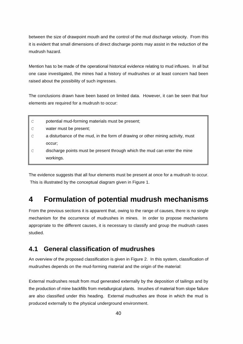
40
between the size of drawpoint mouth and the control of the mud discharge velocity. From this
it is evident that small dimensions of direct discharge points may assist in the reduction of the
mudrush hazard.
Mention has to be made of the operational historical evidence relating to mud influxes. In all but
one case investigated, the mines had a history of mudrushes or at least concern had been
raised about the possibility of such ingresses.
The conclusions drawn have been based on limited data. However, it can be seen that four
elements are required for a mudrush to occur:
C potential mud-forming materials must be present;
C water must be present;
C a disturbance of the mud, in the form of drawing or other mining activity, must
occur;
C discharge points must be present through which the mud can enter the mine
workings.
The evidence suggests that all four elements must be present at once for a mudrush to occur.
This is illustrated by the conceptual diagram given in Figure 1.
4 Formulation of potential mudrush mechanismsFrom the previous sections it is apparent that, owing to the range of causes, there is no single
mechanism for the occurrence of mudrushes in mines. In order to propose mechanisms
appropriate to the different causes, it is necessary to classify and group the mudrush cases
studied.
4.1 General classification of mudrushes
An overview of the proposed classification is given in Figure 2. In this system, classification of
mudrushes depends on the mud-forming material and the origin of the material:
External mudrushes result from mud generated externally by the deposition of tailings and by
the production of mine backfills from metallurgical plants. Inrushes of material from slope failure
are also classified under this heading. External mudrushes are those in which the mud is
produced externally to the physical underground environment.

41
Internal mudrushes involve mud produced by the comminution of shale or other clay-forming
country rocks, and clay mineral rich ores, within the cave muckpile. Mixed mud forming materials
are also grouped in this category - even though some material is formed outside the
underground environment, owing to drawdown, this material mixes with internal mud.
A classification description and proposed mechanisms are given below.
4.1.1 External mudrushes
External mud influxes are produced from three main sources:
C Inrush of tailings or slimes
The inflow of tailings or slimes can occur directly or indirectly. Mechanisms are poor tailings dam
siting, construction and design.
Direct draw of mud from tailings/slimes dam: this is a classic Mufulira situation in which a caving
operation was situated directly below a large tailings dam. Under these conditions the dam
material is drawn into the cave muckpile. The flow of tailings is aided by its high moisture content
and the chimney caving, resulting in tailings fluidity and an ingress channel through the
muckpile. If a clay soil layer exists as a dam foundation, this material precedes the drawdown
of the tailings. Drainage of tailings via the underground drawpoints is then prevented by this
material blocking muckpile voids and acting as a plug. As drawdown increases, the quantity of
tailings entering the muckpile increases, forming a layer above the drawn foundation material
plug. The plug retaining the tailings then fails either by the direct draw of the plug or by
rupturing due to the increased head of tailings above it. The result is the discharge of the
tailings from the muckpile. In addition, as the tailings is discharged into the workings, muckpile
compaction can occur due to collapsing voids, resulting in further tailings being discharged.
Rapid surface subsidence then occurs above the cave. When such a large quantity of tailings
is discharged into the production levels, mine air is compressed causing an air blast. This
mechanism is illustrated in Figure 3.
Indirect flow of tailings: in this mechanism, a tailings dam fails due to poor design, poor water
management, or incorrect construction. Under these condition the dam wall ruptures and a
classic flow slide occurs, with liquefaction of the tailings. As a result the material can flow
unaided towards a shaft, adit or open bench, resulting in an inrush of tailings underground. The
potential of liquefaction of a dam wall and a possible resulting mud rush due to seismic activity

42
cannot be ruled out.
C Failure of placed backfill in underground massive stopes
This failure could occur due to the placement of poor quality backfill in an open stope or VCR
stope. The failure of the backfill could occur during the filling if a drawpoint bulkhead ruptures.
This could be due to poor construction or inadequate design of the bulkhead. Further to this,
a bulkhead could fail if the filled head is greater than the head for which it was designed, or poor
drainage of fill water exists. The magnitude of this type of inrush will be of a local nature
threatening personnel in the near vicinity of the bulkhead.
A danger of mud rushing also exists once the fill has been placed, as poor quality fills could
consist of layers of different strengths in the fill column. If this should occur, then a lower,
weaker layer could slump, creating a void above it in the fill column. Once this has occurred, the
upper fill column is only supported by frictional resistance and the strength of the stronger fill
layers. If this resistance is overcome then the column moves down rapidly, displacing the lower
slumped column out of the stope (ie the upper fill column acts as a pump). When the fill is being
displaced, the mine air in the workings if forced ahead of the mud in the form of an air blast.
The backfill type of mudrush could occur during VCR panel mining or egg crate open stoping,
during the mining of secondary stopes. A further consideration is mudrushing due to toppling
of open stope fill walls of inadequate strength into adjacent drawpoints.
In all of these cases the presence of water reduces the strength of the backfill and therefore the
need for effective stope drainage.
The mechanisms of stope backfill mudrushes are given in Figures 4 and 5.
• Mud rushes due to slope failure
In this case the influx of mud into the workings is due to the failure of an open cut slope directly
above the open stope, open bench or fissure mine drawpoints. Failures may take the form of
circular slips in a soft weathered rock or soil, or failures of tailings deposited above fissure
mines or open cut drawpoints. In a saturated or partially saturated condition, failure could occur
resulting in the inrush of slope material to the underground workings via drawpoints. A special
case of this is in the early mining of a diamond fissure or greenstone gold deposit, in which
continuous slope failure results in accumulation of mud forming material in the mine muckpile.
Figures 6 and 7 show this mechanism.

43
4.1.2 Internal mudrush mechanisms
The type of mudrushes that have been experienced for approximately 100 years at Kimberley
mines fall into this classification. The mud is formed internally during drawdown of the waste
capping above the orebody. Mixed mud rushes are included in this classification, due to the
mixing of internally and externally generated mud materials within the muckpile. The proposed
mudrush mechanisms are given below.
Muckpile/waste capping mudrushes: in this type of mud rush, shale waste rock falls from the
slopes of the open mine. The shale accumulates at the pit bottom. The shale has already been
subjected to slaking in the pit slopes and is further weathered by rain and groundwater which
accumulates at the bottom of the open pit. The shale is then drawn down into the waste capping
and mixed with remnant kimberlite. The waste capping consists of a mixture of materials with
differing fragment sizes. The different fragmentation distribution in the waste capping results in
zones with variable void ratios - the waste capping consists of a honeycomb of large rocks, with
fine shale and kimberlite accumulating in the voids. The honeycomb consists of rock arches
which collapse and reform in a concertina fashion as drawdown proceeds. The weathered shale
and kimberlite flow from void to void lubricating the process. In such an environment the
abovementioned materials are comminuted to a soil state, thus liberating clay minerals.
The ground and rain water that enters the waste capping percolates through the voids and is
absorbed by the comminuted shale and kimberlite to form mud. Since the fines only accumulate
in the waste capping voids, the mud takes a pocket form. For the mud to form in the voids the
waste capping must be stationary for some period of time. This may occur during periods of
mine closure, during the establisment of new mining blocks or when areas are not drawn. The
density of the mud increases under compaction as arches collapse with increased draw. It is
postulated that, due to the ability of the comminuted materials to absorb water, the mud will have
limited flow potential.
With continued drawing the interface between the waste capping and the ore muckpile moves
closer to the drawpoint. At a certain point, dilution from the waste capping (possibly containing
mud pockets) enters the ore draw column and eventually reports to the drawpoint. Since the
mud pockets are contained in the waste capping, their presence must be associated with dilution
ingress. The pocket occurrence of the mud does not neccessarly mean that drawing of waste
cap dilution will result in automatic mud discharge, due to the random occurrence of the pockets.
However, increased extraction and dilution draw increases the probability of occurrence of a
mudrush.

44
This mechanism is shown in Figure 8.
Secondary waste capping/muckpile mudrush mechanisms: the above discussion of an
hypothesized mudrush mechanism does not account for the role of rapid muckpile compaction,
mud pocket migration and possible build up of water head in the waste capping due to mud
plugging of the waste cap/muckpile. The observations made in Section 2 indicate that these
aspects were possibly present in three of the accident cases examined. These factors are
considered as secondary mechanisms and their role is given below.
CC Rapid muckpile compaction
Rapid muckpile compaction (Figure 9) can be seen as the mechanism responsible for mud
pocket discharge. The muckpile waste capping takes the form of a honeycomb of coarse rock
arches, with mud pockets and fines accumulating in the arch voids. Under drawdown these
arches collapse and new arches form further up the draw column. It is therefore postulated that
if a mud pocket is situated in a draw column near to a drawpoint mouth and a large muckpile rock
hangup occurs directly above it, with increasing draw a large void is created as the ore below
is extracted. If this void collapses then a strong enough force to discharge the mud pocket into
the workings may occur. An air blast could result as the mud plug is forced along the drifts. In
addition, with the collapse of the rock arch and compaction of the draw column, surface
subsidence may be observed afterwards.
The formation of a muckpile arch could occur during excessive localised extraction from an
isolated drawpoint. The collapse of the rock arch may occur if material is extracted from arch
"legs" by the reopening of adjacent drawpoints.
CC Flow of mud pockets within the waste capping or muckpile
In the mechanism described above, it has been assumed that mud pockets form in a random
manner in the muckpile. This assumption has been based on the fact that, for a mud pocket to
occur, the following conditions must exist:

45
- a rock arch void must exist of sufficiently large dimensions;
- a sufficiently large quantity of comminuted clay bearing ore or waste must be
present in the void;
- the mud-forming material must be in contact with water;
- the muckpile/waste capping must be stationary for a sufficient time interval for mud
to be generated.
In view of the above and the reported density of the mud in Section 3, the ability of the mud
pockets to move vertically and horizontally within the muckpile must be questioned. The density
of the mud was stated as 2.62 tonnes/m3, which is similar to many muckpile rock fragments.
From these properties it is clear that the mud must act in a similar fashion to other muckpile
fragments.
Research work conducted in Zimbabwe (Heslop, 1984) with respect to ore draw patterns showed
the following:
- material reporting to drawpoints tends to come from less dense areas such as
previously caved and drawn blocks;
- draw columns tend to be inclined towards areas of higher superincumbent loads;
- the tendency for draw columns to be inclined towards the more finely fragmented
ground.
From these observations it can be concluded that draw zones will be inclined towards areas of
high dilution ingress where a greater overburden exists. This interpretation is based on the fact
that significant quantities of waste cap dilution will be finer. If mud pockets are associated with
dilution, which is comminuted shale and kimberlite, then it is evident that pocket movement in the
muckpile/waste cap should follow the same patterns as dilution.
At Miami Mine in Arizona (Heslop, 1984), draw markers moved 60m from one block to another
during drawdown. From Cases 1 and 2 it appears that mud pockets may have moved 15m
vertically, since it was reported that a mudrush had occurred on the previously mined sublevel.
These examples may indicate the possible magnitudes of movement which mud pockets could
experience during extraction. The important point to note is that mud pockets do not move only

46
vertically, but follow the flow of dilution from which they were formed. This is of relevance when
considering the practicality of mud pocket location and neutralization.
C Reduced muckpile/waste capping drainage
In the case of the Mufulira inrush, it was hypothesized that the draw of the dam base material
plugged muckpile voids, retaining the tailings. The plug material then reduced the muckpile
drainage. It is therefore necessary to examine the role of reduced muckpile/waste capping
drainage, and the following scenario is examined.
Mud pockets are produced according to the mechanisms described previously and are drawn
down from the waste capping into the ore muckpile. If the orebody tapers then, at a certain
stage, mud pockets move closer together. From a mine drainage point of view, water enters the
muckpile and flows out of the drawpoints and is pumped to surface. Early in the life of the mine
the quantity of water reporting to the mine pumps should be equal to amount entering the waste
cap/muckpile (minus losses due evaporation, muckpile material absorption and mine
reticulation). However, as mud pockets are formed the waste cap/muckpile permeability is
reduced and the quantity of water pumped from the mine reduces. As drawdown increases and
pockets move closer together, waste cap/muckpile drainage reduces further and water is
retained (Figure 8). The significance of water retention in the waste cap/muckpile is:
- further formation of mud pockets;
- the fluidization of existing mud pockets;
- the failure of mud pocket plugs resulting in mudrushes;
- the possibility of mine flooding after the occurrence of a mudrush.
At present no firm evidence exists to substantiate the above theory. However, it does highlight
the importance of monitoring mine pumping rates over time. It further shows that there may be
a link between flooding and mudrushes and that a flood may follow a mudrush.
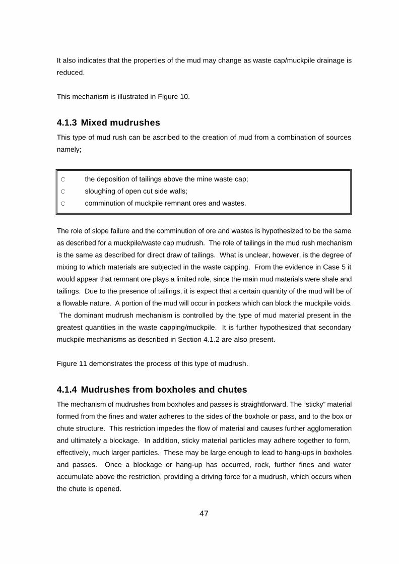
47
It also indicates that the properties of the mud may change as waste cap/muckpile drainage is
reduced.
This mechanism is illustrated in Figure 10.
4.1.3 Mixed mudrushes
This type of mud rush can be ascribed to the creation of mud from a combination of sources
namely;
C the deposition of tailings above the mine waste cap;
C sloughing of open cut side walls;
C comminution of muckpile remnant ores and wastes.
The role of slope failure and the comminution of ore and wastes is hypothesized to be the same
as described for a muckpile/waste cap mudrush. The role of tailings in the mud rush mechanism
is the same as described for direct draw of tailings. What is unclear, however, is the degree of
mixing to which materials are subjected in the waste capping. From the evidence in Case 5 it
would appear that remnant ore plays a limited role, since the main mud materials were shale and
tailings. Due to the presence of tailings, it is expect that a certain quantity of the mud will be of
a flowable nature. A portion of the mud will occur in pockets which can block the muckpile voids.
The dominant mudrush mechanism is controlled by the type of mud material present in the
greatest quantities in the waste capping/muckpile. It is further hypothesized that secondary
muckpile mechanisms as described in Section 4.1.2 are also present.
Figure 11 demonstrates the process of this type of mudrush.
4.1.4 Mudrushes from boxholes and chutes
The mechanism of mudrushes from boxholes and passes is straightforward. The “sticky” material
formed from the fines and water adheres to the sides of the boxhole or pass, and to the box or
chute structure. This restriction impedes the flow of material and causes further agglomeration
and ultimately a blockage. In addition, sticky material particles may adhere together to form,
effectively, much larger particles. These may be large enough to lead to hang-ups in boxholes
and passes. Once a blockage or hang-up has occurred, rock, further fines and water
accumulate above the restriction, providing a driving force for a mudrush, which occurs when
the chute is opened.
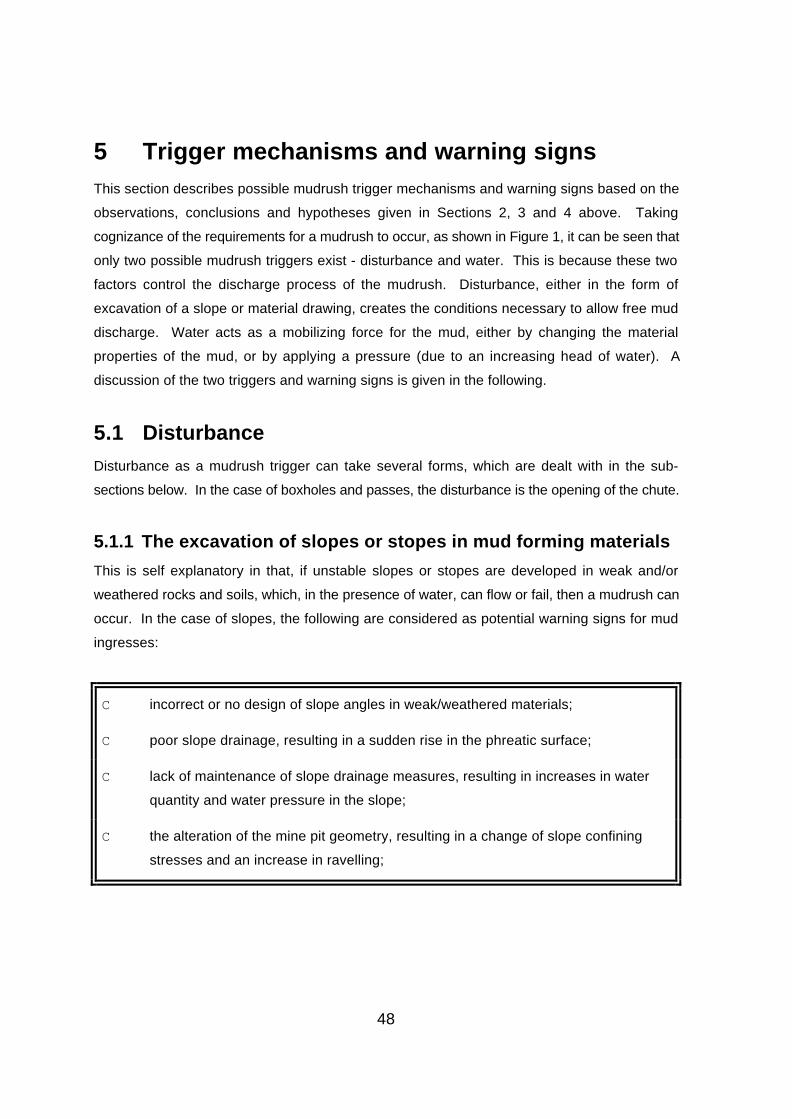
48
5 Trigger mechanisms and warning signsThis section describes possible mudrush trigger mechanisms and warning signs based on the
observations, conclusions and hypotheses given in Sections 2, 3 and 4 above. Taking
cognizance of the requirements for a mudrush to occur, as shown in Figure 1, it can be seen that
only two possible mudrush triggers exist - disturbance and water. This is because these two
factors control the discharge process of the mudrush. Disturbance, either in the form of
excavation of a slope or material drawing, creates the conditions necessary to allow free mud
discharge. Water acts as a mobilizing force for the mud, either by changing the material
properties of the mud, or by applying a pressure (due to an increasing head of water). A
discussion of the two triggers and warning signs is given in the following.
5.1 Disturbance
Disturbance as a mudrush trigger can take several forms, which are dealt with in the sub-
sections below. In the case of boxholes and passes, the disturbance is the opening of the chute.
5.1.1 The excavation of slopes or stopes in mud forming materials
This is self explanatory in that, if unstable slopes or stopes are developed in weak and/or
weathered rocks and soils, which, in the presence of water, can flow or fail, then a mudrush can
occur. In the case of slopes, the following are considered as potential warning signs for mud
ingresses:
C incorrect or no design of slope angles in weak/weathered materials;
C poor slope drainage, resulting in a sudden rise in the phreatic surface;
C lack of maintenance of slope drainage measures, resulting in increases in water
quantity and water pressure in the slope;
C the alteration of the mine pit geometry, resulting in a change of slope confining
stresses and an increase in ravelling;
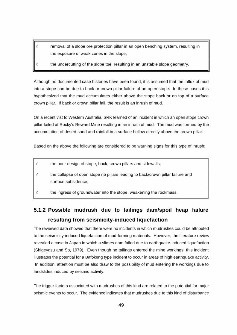
49
C removal of a slope ore protection pillar in an open benching system, resulting in
the exposure of weak zones in the slope;
C the undercutting of the slope toe, resulting in an unstable slope geometry.
Although no documented case histories have been found, it is assumed that the influx of mud
into a stope can be due to back or crown pillar failure of an open stope. In these cases it is
hypothesized that the mud accumulates either above the stope back or on top of a surface
crown pillar. If back or crown pillar fail, the result is an inrush of mud.
On a recent vist to Western Australia, SRK learned of an incident in which an open stope crown
pillar failed at Rocky's Reward Mine resulting in an inrush of mud. The mud was formed by the
accumulation of desert sand and rainfall in a surface hollow directly above the crown pillar.
Based on the above the following are considered to be warning signs for this type of inrush:
C the poor design of stope, back, crown pillars and sidewalls;
C the collapse of open stope rib pillars leading to back/crown pillar failure and
surface subsidence;
C the ingress of groundwater into the stope, weakening the rockmass.
5.1.2 Possible mudrush due to tailings dam/spoil heap failure
resulting from seismicity-induced liquefaction
The reviewed data showed that there were no incidents in which mudrushes could be attributed
to the seismicity-induced liquefaction of mud-forming materials. However, the literature review
revealed a case in Japan in which a slimes dam failed due to earthquake-induced liquefaction
(Shigeyasu and So, 1979). Even though no tailings entered the mine workings, this incident
illustrates the potential for a Bafokeng type incident to occur in areas of high earthquake activity.
In addition, attention must be also draw to the possibility of mud entering the workings due to
landslides induced by seismic activity.
The trigger factors associated with mudrushes of this kind are related to the potential for major
seismic events to occur. The evidence indicates that mudrushes due to this kind of disturbance

50
will be very rare in South Africa.
5.1.3 Disturbance due to drawdown of the cave muckpile
From the information reviewed in Cases 1, 2, 4 and 5, correlation has been established between
isolated draw and mudrushes. These mechanisms have been previously described. The main
danger associated with isolated draw is the high rates of extraction from drawpoints. This results
in an increased possibility of mudrushes due to the fact that dilution from the mud-bearing waste
cap enters the draw column sooner. Also, larger quantities of waste can be drawn from diluted
drawpoints before they are closed, resulting in dilution cut-off of reserves from adjacent
drawpoints. In essence, these heavily extracted drawpoints act as mud pocket pathways to the
operation levels.
As draw rates increase, the fines are normally extracted from the draw column first, leaving a
honeycomb of rock arches and an increased possibility of mud pocket discharge due to rapid
draw column compaction.
With regard to draw trigger mechanisms, the following conditions must be fulfilled, based on the
evidence obtained from Case 1:
C a condition of isolated draw must exist on operational levels. From the draw
control tally sheet submitted as evidence in Case 1, it appears that less than 30%
of drawpoints were operational;
C 30% of drawpoints must be overdrawn (beyond the allocated drawpoint reserves);
C operational drawpoints must have draw rates much higher than common practice
(typically 1.5m/day). For example, draw rates of 8m/day are favourable for mud
ingress.

51
It should be noted that these draw rates are probably only applicable to SLC mining. In block
cave mining, due to the fragmentation requirement, draw rates in the region of 200mm/day are
considered normal. However, isolated draw conditions can still occur in block caving and the
danger of mud ingress due to excessive over extraction still exists.
From the above discussion it is apparent that, for mud ingress to occur, isolated drawpoints must
be extracted in excess of the allocated reserves. It therefore follows that non-interactive draw
conditions are a warning sign of mudrushes in caving operations. It is apparent that the process
which results in drawpoints being extracted in isolation must be fully understood if the triggering
of mud influxes due to draw is to be prevented. As mentioned in Section 2, isolated draw
conditions can occur due to poor draw discipline (drawpoints deliberately over pulled), or due
to poor layout design. Even though instances of poor draw discipline do occur at most
operations, experience indicates that uniform drawdown is generally achieved at most profitable
caves, unless waste cap mining is economic. Over the last 30 years, much work has been done
on the determination of interactive drawpoint spacings. If the empirical design rules are applied
then there is no reason why interactive draw conditions cannot be achieved.
Figure 12 shows the process which results in isolated draw conditions occurring in a SLC or
block cave. Non-interactive draw normally begins when drawpoints or drifts are lost due to the
following:
C ground control problems requiring drift repairs;
C ground control problems due to excessive action blasting (blasting for drawpoint
hang-up clearance);
C the formation of crown pillars, bridges or banks due to poor blast design and
practice. This is non-extraction of the full fan profile, which results in remnant
pillars remaining in the fan blast geometry;
C destruction of drifts by point loading due to poor action work;
C destruction of drifts or drawpoints due to loading from remnants left on previously
mined levels;
C drawpoints lost due to non-mining of areas where there has been a mud
occurrence or where mud pockets are suspected.

52
The result of the initial loss of drawpoints or drifts is that, if the level or block tonnage (call) is not
reduced, then the remaining drifts and drawpoints will be extracted above their natural capacity.
The usual result is that ore fragmentation size reporting to drawpoints increases. Consequently,
the frequency with which action blasting of drawpoints (to clear hang-ups) is conducted also
increases. This causes additional drawpoints to be lost due to blast damage. Again, if the call
is maintained the remaining drawpoints are extracted above their natural capacity and the
process is repeated until excessive dilution of ore reserves occurs or the block is lost due to mud
ingress.
5.2 Water
From the case histories and accident reports it is clear that water has had a role in mud
formation and the inrush triggering process. The triggering mechanisms associated with water
were hypothesized in Sections 4.1 and 4.2. The important role of water is given in Section 2.
At present no data are available to substantiate the theories presented in Section 4. However,
it is considered that these theories are logical, and are based on engineering judgement and
the experience of SRK engineers. It is possible that information from De Beers mines may help
to validate the hypotheses, if such information becomes available in the future.
In an attempt to overcome the limited information, consideration was given to modelling the
process of water retention and reduced drainage of the muckpile. This was abandoned,
however, since it was believed that this would probably not be convincing - analyses can be
manipulated to give any desired result.
It is therefore not possible to give specific values relating to water as a major mudrush trigger.
However, based on the investigation, the following are considered as possible mudrush warning
signs:

53
C lack of a correctly designed mine drainage system;
C poor maintenance of the mine drainage system. In this respect, particular note
must be taken of the following:
C if the mine drainage system consists of a network of drainage galleries: the
collapse of these tunnels, the calcification and blockage of drain holes and
underground drains;
- if mine dewatering is achieved by the use of borehole pumps: the
vandalism and theft of pumps, and the collapse of dewatering boreholes;
- blockage of surface drainage trenches by undergrowth, and their collapse;
- surface ponding;
C decreasing mine pumping rates over time, but with a theoretical increase in mine
water. Figure 13 shows a theoretical model depicting muckpile water retention
which can be used as a warning;
C small underground floods and mudrushes;
C the increased presence of water underground.
With regard to boxholes and passes which contain material and in which there is water entry, a
warning sign will be the absence of water draining from the chute or box front. The implication
is that a blockage has occurred allowing water and material to build up behind it.
6 Risk assessmentIn this section, a description will be given of the application of fault tree methodology to
mudrushes. A mudrush can occur under many different circumstances and a generic fault tree
was therefore developed to take into account most of these circumstances. Four examples of
mudrushes, each occurring under different circumstances, have been analysed, using this
methodology, to illustrate the application of the risk assessment technique. Specific fault trees
were assembled from the generic fault tree to represent each of the particular circumstances
applicable in each example. The factors that influence the probability of occurrence of
mudrushes are tested for significance.

54
6.1 Fault tree methodology
The failure of any system, for example, a tailings dam, is seldom the result of a single cause, or
fault. Failure usually results when a combination of faults occurs in such a way that the demands
on the system exceed the capacity of the system to resist those demands. A systematic
approach is therefore required to determine the logic that controls the failure of the system and
to analyse the potential consequences of failure. One such approach, is the Fault-Event Tree
Analysis. A more detailed description of the Fault-Event Tree Analysis is contained in Appendix
G.
Fault tree analysis (FTA) is a quantitative technique in which conditions and factors that can
contribute to a specified undesired incident (called the top fault) are deductively identified and
organised in a logical manner. Starting with the top fault, the possible causes or failure modes
(primary faults) on the next lower functional system level are identified. Following the step-by-
step identification of undesirable system operation to successively lower levels will lead to the
desired system level, which is usually the component failure mode. FTA affords a disciplined
approach that is highly systematic, but at the same time sufficiently flexible to allow analysis of
a variety of factors. The application of the top-down approach focuses attention on those effects
of failure which are directly related to the top fault.
The systematic nature of the fault-event tree enables the sensitivities of the potentially adverse
consequences to any of the causative hazards to be evaluated. This enables the most
threatening causative hazards to be identified and eliminatory measures to be defined.
Not every failure may lead to the consequence that is under investigation (e.g. loss of life). In
order to facilitate modelling and computation of the possible consequences (or events) of a
failure, an “event tree” is used. The “event tree” is developed by assigning probabilities of
affirmative answers to a series of definitive questions in such a way that lesser consequence
events are systematically eliminated and the probability of the top event can be calculated. The
final result, or probability of occurrence of a consequence arising from failure is thus determined
by means of a combined “fault-event tree”.

55
6.2 Structure of generic fault tree
The generic fault tree is modular, with each trunk representing a different mechanism. Trunks
are linked logically by cause and effect. A tree should be assembled by first identifying the top
fault. This will be the occurrence of a mudrush at a strategic point. Then the causes need to be
identified based on the circumstances under which a mudrush could occur. Several different
mechanisms are described in the generic fault tree and only those that are applicable to the
given circumstances, should be considered.
The structure of the generic fault tree is given in Appendix B. Four generalised locations or
strategic points, where mud rushes can occur, were identified. These are:
- at a cave drawpoint;
- at an entrance to an open stope;
- in a service excavation, or
- at a shaft.
Four main trunks were then drawn up which describe the flow of mud to these strategic
points. The four trunks are as follows:
Trunk 1: Mudrush from cave
Trunk 2: Mudrush from open stope
Trunk 3: Mudrush through service excavation
Trunk 4: Mudrush through shaft
All of these trunks have the same basic structure. There must be a source of mud and there
must be freedom for the mud to flow through or discharge from an excavation.
In the first two trunks (caves and open stopes), mud can be formed internally or accumulated
from other sources. However, in the third and fourth trunks (service excavations and shafts),
the mud must accumulate from other sources. For mud to be formed internally there must be
an accumulation of mud forming materials (Trunk B) and an accumulation of water (Trunk A).
The accumulation of mud from other sources is described in Trunk C.

56
In a cave operation the mud would flow through a draw plug and discharge at the draw point. If
the draw plug is competent the flow of mud will be minimised. The competency of the draw plug
is described in Trunk D. The freedom to discharge from or flow through other excavations is
described in Trunk E.
Trunk A: Accumulation of water
For water to accumulate in an excavation there must be a source of water and a mechanism by
which it flows into the excavation. Fifteen potential sources of water were identified and
described as trunks A1 to A15 of the generic fault tree. These include groundwater, service
water, underground dams, surface dams, slimes dams, open pit bottoms, adjacent caves, stopes
or service excavations, shafts, backfill, discontinuous subsidence, drainage galleries, surface
water and pit slopes. Not all of these will apply to a specific case and only those that do should
be included. The transport of water from the source to the excavation is described in Trunk X.
Groundwater could occur in an aquifer or a water bearing structure (Trunk A1). Usually, when
groundwater is a potential problem, drainage systems are implemented. Drainage galleries are
commonly used and these need to be well designed and maintained to ensure effective
drainage. If these drainage galleries are not well maintained, the drainage galleries may become
flooded and water may flow into another excavation (Trunk A13).
Service water can accumulate in excavations if its use is not controlled and pipes, hoses and
fittings are not well maintained (Trunk A2).
Water can flow from underground dams, surface dams or slimes dams, if they are overfilled, the
dam wall fails, or leakage occurs (Trunks A3-A5). The design and construction of these dams
is important to prevent failure of dam walls. For slimes dams, construction and maintenance is
an ongoing process and good management of this process is essential.
Where an open pit has been mined and subsequent underground operations have started,
water could flow from the open pit into the underground workings (Trunk A6). Rain water, or
water from other sources, can accumulate in the open pit. The other sources include all of the
applicable sources under Trunk A, such as surface dams, slimes dams, and groundwater. If no
crown pillar is left, as in a cave operation immediately below the pit, the water will flow directly into
the excavation. A failed crown pillar will also allow water to flow directly into an excavation below.
Other possible flow mechanisms are covered in Trunk X.

57
Water can accumulate in one excavation and flow into another (Trunk A7-A10). The flow
mechanisms are described in Trunk X.
Excessive water can accumulate in backfill, if the backfill design or quality control is poor, or if
water is absorbed into the backfill from other sources (Trunk A11). If the transport of this water
is uninhibited it can flow into an excavation (Trunk X).
If discontinuous subsidence occurs and there is an accumulation of water, the water could flow
into an underground excavation (Trunk 12). Two possible mechanisms of discontinuous
subsidence are described.
Where naturally occurring surface water, rivers and lakes could become a problem, the water
is normally drained or re-directed (Trunk A14).
Water can accumulate in slopes from rain water or groundwater and form mud (Trunk A15). If
this is a problem, the slopes are usually drained using borehole pumps, surface drains, bench
drains, bench depressurising holes or combinations of these. The design and maintenance of
the slope drainage systems is extremely important.
Trunk X: Transport of water uninhibited
Two flow mechanisms are described, transport of water through geological discontinuities (Trunk
X1) and transport directly to the excavation (Trunk X2).
Where geological discontinuities transport water, the discontinuity must connect from the source
of water to the receiving end, and it must allow flow of water.
Alternatively, a pathway to an excavation must be present and the gradient must be sufficient
to allow flow of water. In some cases, the flow of water can be inhibited by certain measures.
A concrete plug can be installed at an entrance to an old excavation to prevent flow of water
from this excavation. The plug must be well designed and maintained. In some working service
excavations, water control measures can be used to prevent large flows of water. These include
reverse drains, water stulls, bulkheads, watertight doors and pumping systems. The
performance of these systems depends on their location, design, construction, maintenance and
other factors.
58
Trunk B: Accumulation of mud forming materials
Mud forming materials may accumulate in a cave, in an open stope or in an open pit, where they
can mix with water to form mud. For an accumulation of mud forming materials, there must be
a potentially mud forming source rock which accumulates and a comminution or weathering
process to break the rock down. Shale and kimberlite have a high potential to form mud when
broken down compared with quartzite, granite and similar rock types. The drawing of ore from
a cave or an open stope is a comminution process and the nature of the drawing process will
influence the effectiveness of the comminution process. Exposure to water or air for long
periods of time will allow the rock material to weather.
Ore will accumulate in caves and open stopes, as part of the mining method, and if the ore has
a high potential to form mud and there is water present, mud will be formed internally. Mud
forming materials could accumulate from the host rock or crown pillar if they fail. The layout
design is therefore important to prevent failure of the host rock or crown pillars (Trunk B1).
In a cave operation below an open pit with no crown pillar in between, mud forming materials
which accumulate in the pit could flow directly into the cave (Trunk B2). Mud forming materials
could accumulate from a slope failure or the pit bottom rock itself. Dry tailings could accumulate
from deposition or a slimes dam failure.
Trunk C: Accumulation of mud from other sources
Mud can accumulate in an excavation from the four main sources - caves, open stopes, service
excavations, and shafts (Trunks 1 – 4). A mudrush from one excavation can flow into another,
causing injury or damage at another location. Alternative sources of mud include open pit
bottoms, backfill, slimes dams, pit slopes, discontinuous subsidence and a surface accumulation
of mud. The first five sources are described in detail in Trunks C1 - C5.
Mud can be formed internally in an open pit or it can accumulate from other sources (Trunk C1).
For mud to be generated internally there must be an accumulation of mud forming materials
(Trunk B2), which is described above, and an accumulation of water (Trunk A). This mud can
flow into an excavation below if there is no crown pillar or if the crown pillar fails.
Post backfilling of open stopes is normally done in a series of lifts. For the first lift, a bulkhead
must be designed and constructed to prevent backfill from flowing out of the stope. Once the
backfill has consolidated, the first lift forms a bulkhead for the second lift. Each lift then becomes

59
a bulkhead, after consolidation, for the following lift. A mudrush can occur if the initial bulkhead
fails or if the backfill does not consolidate (Trunk C2). To ensure consolidation of backfill, the
design of water content, backfill grading and cement content must be correct. Effective quality
control, which incorporates monitoring and rectification of deviations from the design, must be
instituted in good time. An accumulation of water in the backfill from other sources could also
prevent consolidation of the backfill (Trunk A).
A mudrush could occur from a slimes dam if there is a failure of the dam (Trunk C3). It is
important that the appropriate design technology is applied during design. The design must take
into account the type and quality of the slimes material. Since the construction of a slimes dam
is an ongoing process, this needs to be well managed to ensure that the design requirements
are met. Maintenance of the slimes dam is also important. However, if failure of a slimes dam
occurs, the mud will only flow into an excavation if there is a direct pathway (Trunk E).
If a pit slope becomes saturated with water, it could fail and mud could flow into an excavation
(Trunk C4). For this to occur the slope material must have a high potential to form mud and
there must be an accumulation of water. The accumulation of water in pit slopes is discussed
above (Trunk A15).
Mud could flow through the fractures formed during discontinuous subsidence (Trunk C5) if
there is an accumulation of mud where the subsidence occurs. Discontinuous subsidence could
occur when the hangingwall in an open stope fails and caving continues to surface, or when a
block bounded by major geological discontinuities subsides.
Trunk D: Draw plug incompetent
In an operation where the ore is drawn from the excavation through a number of drawpoints, the
broken ore forms a draw plug. This draw plug, to a greater or lesser extent, resists the flow of
accumulated mud through the drawpoints. The mechanisms for a live operation (dynamic) and
one that has been abandoned (static) are both included in the tree. An abandoned operation
may be connected to excavations where people are working and the risk will therefore need to
be considered.
In a dynamic situation, the amount of extraction that has taken place will affect the competency
of the draw plug considerably. The thickness of the draw plug is gradually reduced as the ore
is drawn. Locally the draw plug can be incompetent if mud pockets are unfavourably located or
draw control is poor, and the draw plug becomes punctured. If the thickness is reduced and

60
there is local incompetence in the draw plug, a mudrush has a greater chance of occurring. If
there is an accumulation of mud, then mud pockets will be drawn into the draw plug and their
distribution will be random. This cannot be controlled and if a mud pocket is located immediately
above a drawpoint, it will flow through the drawpoint. Draw control is important to ensure that
all drawpoints are drawn evenly and no individual drawpoints are drawn excessively. If one
drawpoint is drawn excessively, the draw plug may be punctured, allowing mud to flow through
the drawpoint.
After drawing is completed and the operation is abandoned, the competency of the draw plug
is dependent on the status of the draw plug at the time of abandonment. The greater the
amount of extraction that has taken place, the less competent the draw plug will be. Local
incompetence in the draw plug can be caused by continuous open channels, a string of
interconnected voids and unfavourably located mud pockets. A concrete plug can be installed
in the drawpoints to contain the flow of mud. These will need to be correctly designed and
constructed.
In an abandoned operation, it is likely that drainage of groundwater will be stopped and that
more mud will be formed internally. This is taken into account in Trunk A under the main trunk,
Trunk 1.
Trunk E: Freedom to discharge
Mud can flow freely if there is a direct pathway to the excavation, the gradient is sufficient and
there are no measures to inhibit the flow of mud. The structure of this tree is the same as Trunk
X2. The measures used to inhibit the flow of water will also inhibit the flow of mud. However,
these measures will be less effective in resisting the flow of mud, and this must be taken into
account when assigning probabilities to the tree.

61
6.3 Risk assessment examples
Four examples of risk assessments are discussed in this section:
- internally generated mud for a cave mine scenario;
- external mudrush from a slimes dam;
- backfill mudrush in a post fill stope, and an external mudrush from
an open pit slope failure.
The fault trees relevant for each of these are assembled appropriately from the trunks of the
generic tree. Trunks are numbered using the numbering system in the generic tree. If Trunk
2 (mud rush from an open stope) is selected from the generic tree, it is labelled Trunk 2 in the
example. A sub trunk falling under Trunk 2 is labelled Trunk 2C, where C represents “Trunk C:
accumulation of mud from other sources” in the generic tree.
The structure of the fault trees has been simplified for clarity. Probabilities of occurrence have
been assigned to the causes in the fault tree. Many trunks refer to a sub trunk. When these sub
trunks have been considered as unimportant in demonstrating the objective, they have been
excluded, and probabilities of occurrence have then been assigned at the higher level.
Sensitivity analyses were carried out by varying the probabilities of occurrence for some of the
causes. Combinations of relatively high and low probabilities, were assigned to each of the
variable causes, to represent a scenario. Six different scenarios were analysed for each
example. The fault tree structures and results of these analyses are listed in Appendices C to
F. In these appendices, the probabilities of occurrence for variable causes are highlighted in
dark grey. Where causes, at a higher level, are affected by the changes, the probabilities of
occurrence are highlighted in light grey.
Example 1: Internally generated mud for cave mine scenario
Background
In this example, mud is generated internally in the cave. Mud is formed by water mixing with the
comminuted kimberlite. Water accumulates mainly from groundwater, and drainage galleries are
used to minimise the flow of groundwater into the excavation. The effects of poor maintenance
of drainage galleries are tested. The influence of draw control and the amount of draw that has
taken place are also investigated. The fault tree and the results of the sensitivity analysis are
given in Appendix C.

62
Structure of fault tree
The strategic point identified, where the mudrush can occur, is the drawpoint of the cave. Trunk
1 (mudrush from cave) was used as the starting point. The accumulation of mud forming
materials and water are analysed in Trunks 1A and 1B. The competency of the draw plug is
analysed in Trunk 1D.
In Trunk 1A, four sources of water are considered - groundwater (Trunk 1A1), water ingress from
an open pit bottom, water ingress from other service excavations and water ingress from
drainage galleries. In this example, water from the open pit bottom and water from service
excavations were considered to be less significant and relatively low probabilities of occurrence
were assigned at this level. Under Trunk 1A1 there is a definite accumulation of groundwater.
The probabilities of occurrence for the maintenance of drainage galleries were varied to
illustrate the influence of effective drainage. Water is transported mainly through geological
discontinuities, Trunk A1X, and a probability of 1,0 was assigned, indicating that there is a
definite flow path. Water ingress from drainage galleries, Trunk A13, is possible if maintenance
is poor and the galleries become flooded. The causes “pump fails” and “poor maintenance”
under “drain blocked” were varied. Transport of water is again mainly along geological
discontinuities and the same assumptions apply. The probability of water being transported
directly to the excavation was increased, but this has a negligible influence on the result.
There is an accumulation of mud forming materials, Trunk 1B. All of the mud forming material
comes from the ore, which has a high potential to form mud. The probabilities of occurrence
under this trunk were kept constant.
The draw plug was analysed under dynamic conditions only and the static branch was assigned
a probability of 0.0 at the highest level (Trunk 1D). The probabilities for the causes “excessive
uniform extraction of draw plug (thickness reduced)” and “draw control inadequate (puncturing)”
were varied to show the effect of over extraction and poor draw control.
Sensitivity analysis
The parameters that were tested for sensitivity are listed in Table 1. H and L represent relatively
high and low probabilities assigned.
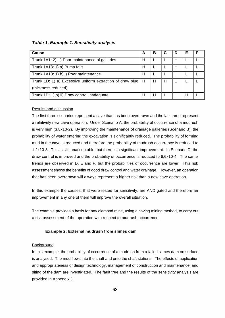
63
Table 1. Example 1. Sensitivity analysis
Cause A B C D E F
Trunk 1A1: 2) iii) Poor maintenance of galleries H L L H L L
Trunk 1A13: 1) a) Pump fails H L L H L L
Trunk 1A13: 1) b) i) Poor maintenance H L L H L L
Trunk 1D: 1) a) Excessive uniform extraction of draw plug
(thickness reduced)
H H H L L L
Trunk 1D: 1) b) ii) Draw control inadequate H H L H H L
Results and discussion
The first three scenarios represent a cave that has been overdrawn and the last three represent
a relatively new cave operation. Under Scenario A, the probability of occurrence of a mudrush
is very high (3,8x10⁻²). By improving the maintenance of drainage galleries (Scenario B), the
probability of water entering the excavation is significantly reduced. The probability of forming
mud in the cave is reduced and therefore the probability of mudrush occurrence is reduced to
1,2x10⁻³. This is still unacceptable, but there is a significant improvement. In Scenario D, the
draw control is improved and the probability of occurrence is reduced to 6,6x10⁻⁴. The same
trends are observed in D, E and F, but the probabilities of occurrence are lower. This risk
assessment shows the benefits of good draw control and water drainage. However, an operation
that has been overdrawn will always represent a higher risk than a new cave operation.
In this example the causes, that were tested for sensitivity, are AND gated and therefore an
improvement in any one of them will improve the overall situation.
The example provides a basis for any diamond mine, using a caving mining method, to carry out
a risk assessment of the operation with respect to mudrush occurrence.
Example 2: External mudrush from slimes dam
Background
In this example, the probability of occurrence of a mudrush from a failed slimes dam on surface
is analysed. The mud flows into the shaft and onto the shaft stations. The effects of application
and appropriateness of design technology, management of construction and maintenance, and
siting of the dam are investigated. The fault tree and the results of the sensitivity analysis are
provided in Appendix D.

64
Structure of fault tree
The strategic point identified, where the mudrush can occur, is the shaft station. Trunk 4
(mudrush through shaft) was selected as the main trunk. Mud is accumulated from other
sources, Trunk 4C, and the freedom to discharge is covered in Trunk 4E. Under Trunk 4E,
there is a clear pathway to the shaft station, a steep gradient and there are no measures to
inhibit the flow of mud. The mud will definitely flow through the shaft and a probability of 1,0 was
assigned.
The other sources of mud that are considered in Trunk 4C are “mudrush from slimes dam”
(Trunk 4C3) and “surface accumulation of mud”. The probability of a surface accumulation of
mud was assigned a low value at the highest level. Under trunk 4C3, the capacity of the dam
being exceeded, causing a large flow of mud was considered unlikely. A low probability was
assigned and this was not varied. The probabilities for the use of inappropriate design
technology and the inadequate application of design technology were varied separately. The
management of slimes dams was also tested for sensitivity. The flow of mud from the slimes dam
to the shaft is covered in Trunk 4C3E. The siting of the slimes dam will determine whether there
is a pathway to the shaft and whether the gradient is sufficient to allow the flow of mud. These
parameters were tested for sensitivity. There are no measures prevent the flow of mud.
Sensitivity analysis
The parameters that were tested for sensitivity are listed in Table 2. H and L represent
relatively high and low probabilities assigned.
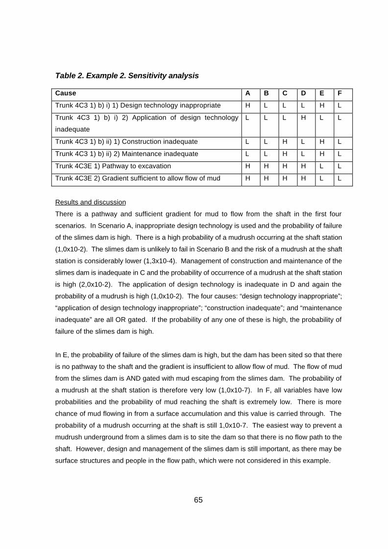
65
Table 2. Example 2. Sensitivity analysis
Cause A B C D E F
Trunk 4C3 1) b) i) 1) Design technology inappropriate H L L L H L
Trunk 4C3 1) b) i) 2) Application of design technology
inadequate
L L L H L L
Trunk 4C3 1) b) ii) 1) Construction inadequate L L H L H L
Trunk 4C3 1) b) ii) 2) Maintenance inadequate L L H L H L
Trunk 4C3E 1) Pathway to excavation H H H H L L
Trunk 4C3E 2) Gradient sufficient to allow flow of mud H H H H L L
Results and discussion
There is a pathway and sufficient gradient for mud to flow from the shaft in the first four
scenarios. In Scenario A, inappropriate design technology is used and the probability of failure
of the slimes dam is high. There is a high probability of a mudrush occurring at the shaft station
(1,0x10⁻²). The slimes dam is unlikely to fail in Scenario B and the risk of a mudrush at the shaft
station is considerably lower (1,3x10⁻⁴). Management of construction and maintenance of the
slimes dam is inadequate in C and the probability of occurrence of a mudrush at the shaft station
is high (2,0x10⁻²). The application of design technology is inadequate in D and again the
probability of a mudrush is high (1,0x10⁻²). The four causes: “design technology inappropriate”;
“application of design technology inappropriate”; “construction inadequate”; and “maintenance
inadequate” are all OR gated. If the probability of any one of these is high, the probability of
failure of the slimes dam is high.
In E, the probability of failure of the slimes dam is high, but the dam has been sited so that there
is no pathway to the shaft and the gradient is insufficient to allow flow of mud. The flow of mud
from the slimes dam is AND gated with mud escaping from the slimes dam. The probability of
a mudrush at the shaft station is therefore very low (1,0x10⁻⁷). In F, all variables have low
probabilities and the probability of mud reaching the shaft is extremely low. There is more
chance of mud flowing in from a surface accumulation and this value is carried through. The
probability of a mudrush occurring at the shaft is still 1,0x10⁻⁷. The easiest way to prevent a
mudrush underground from a slimes dam is to site the dam so that there is no flow path to the
shaft. However, design and management of the slimes dam is still important, as there may be
surface structures and people in the flow path, which were not considered in this example.
66
Example 3: Backfill mudrush from post fill stope
Background
In this example, a mined out open stope is filled with backfill. The influence of the quality of the
bulkhead and the consolidation of backfill is analysed. Backfill consolidation is controlled
through design monitoring and by preventing additional water from accumulating in backfill. The
source of additional water is service water used in adjacent service excavations. The fault tree
and the results of the sensitivity analysis are provided in Appendix E.
Structure of fault tree
The strategic point identified, where the mudrush can occur, is at the entrance to the open
stope. Trunk 2 (mud rush from open stope) was chosen as the main tree. Since the ore has
been extracted, it is unlikely that mud will be formed internally and a low probability of occurrence
was assigned at this level. The mud accumulates from other sources (Trunk 2C). The entrance
to the excavation is open and the mud will have freedom to discharge.
Under Trunk 2C two sources of mud were selected. A mud rush through development
excavations is unlikely to occur and a low probability was assigned at this level. The main source
of mud is a mudrush from backfill (Trunk 2C2). All of the backfill design parameters in Trunk
2C2 were varied jointly. The probabilities for backfill quality control were also varied jointly. The
accumulation of water from other sources falls under Trunk 2C2A. The probability of failure of
the bulkhead was also varied.
Two sources of water were selected under Trunk 2C2A - groundwater and water ingress from
adjacent excavations (Trunk 2C2A9). Groundwater was assigned a low probability at this level.
Under Trunk 2C2A9 there must be an accumulation of water in the service excavation (2C2A9A)
and the transport of water to the open stope (Trunk 2C2A9X). There is a pathway and the
gradient is sufficient to allow the flow of water (Trunk 2C2A9X2). A concrete plug is used in one
scenario to inhibit the flow of water.
Under Trunk 2CA29A, groundwater and service water were selected. Groundwater was
assigned a low probability at this level. The accumulation of service is covered in Trunk
2C2A9A2. The probabilities for the control of service water were varied.

67
Sensitivity analysis
The parameters that were tested for sensitivity are listed in Table 3. H and L represent relatively
high and low probabilities assigned.
Table 3. Example 3. Sensitivity analysis
Cause A B C D E F
Trunk 2C2: 1) a) Backfill design incorrect L H L L L L
Trunk 2C2: 1) b) Backfill quality control inadequate L L H L L L
Trunk 2C2: 2) Failure of bulkhead L L L H L L
Trunk 2C2A9A2 2) Control of water inadequate L L L L H H
Trunk 2C2A9AX2 3) a) Concrete plug is installed H H H H H L
Results and discussion
In Scenarios A to E there is no concrete plug to prevent water from accumulating in the backfill.
The design of backfill, quality control, competency of bulkhead and control of service water in
adjacent excavations are all good in A and the probability of a mudrush occurring at the stope
entrance is low (1,1x10⁻⁴). In B, C, D and E there is a high probability of occurrence of a
mudrush at the stope entrance and only one cause was changed in each case. All of the
possible causes must be well addressed or there will be a high probability of occurrence of a
mudrush. In F, there is poor control of service water, but additional water is prevented from
entering the excavation with a concrete plug and the probability of occurrence of a mudrush is
low (8x10⁻⁵).
Example 4: External mudrush from slope failure
Background
In this example, the failure of a saturated pit slope causes a mudrush. The mud flows through
a slot into the underground operations. The rock type in the slope is shale and in one scenario
a rock type with a lower tendency to form mud is used. Slope drainage systems are used to
prevent the accumulation of ground water. The influence of poor drainage systems is tested.
The fault tree and the results of the sensitivity analysis are provided in Appendix F.

68
Structure of fault tree
The strategic point identified, where the mudrush can occur, is at the base of the slot. Trunk 3
- mudrush through slot (service excavation) is the main trunk. There must be an accumulation
of mud from other sources (Trunk 3C) and there is full freedom to discharge through the slot.
In Trunk 3C, three sources of mud were selected. Low probabilities were assigned at this level
to “mud rush from slimes dams” and “surface accumulation of mud”. The main source of mud
is from the pit slope (Trunk 3C4).
In Trunk 3C4, the potential for the slope rock to form mud, and the slope angle were varied. The
accumulation of water in the pit slope was also varied and this is covered in Trunk 3C4A15. In
Trunk 3C4A15, the tendency for groundwater to accumulate, and design and maintenance of
the slope drainage measures, were varied.
Sensitivity analysis
The parameters that were tested for sensitivity are listed in Table 4. H and L represent relatively
high and low probabilities assigned.
Table 4. Example 4. Sensitivity analysis
Cause A B C D E F
Trunk 3C4 1) a) Mud forming materials in pit slope H H H H H L
Trunk 3C4 2) Slope angle inadequate for saturated pit slope H H H L H H
Trunk 3C4A15 1) b) Groundwater ingress H H H H L H
Trunk 3C4A15 2) a) Design inadequate L H L L L L
Trunk 3C4A15 2) b) Maintenance inadequate H L L H H H
Results and discussion
In the first four scenarios, the materials in the pit slope have a high tendency to form mud. A, B
and C all have inadequate slope angles, for a saturated slope, and a high tendency for
groundwater ingress. The maintenance of slope drainage systems is inadequate in A and the
design of slope drainage is inadequate in B. The probability of water accumulating in the pit
slope is high and the resulting probability of a mudrush is very high (1,0x10⁻²) in both scenarios.
In C, both the design and maintenance are adequate and the probability of a mudrush is low
(3,0x10⁻⁵). The design and maintenance of slope drainage systems are controlled by an OR gate
and therefore both need to be good to prevent the accumulation of water in the pit slope.
69
In D, the slope angle is designed conservatively to take into account the possible saturation of
the slope. There is a tendency for groundwater to accumulate and the maintenance of drainage
systems is poor. The conservative slope angle reduces the probability of the slope failure and
therefore the probability of a mudrush (1,1x10⁻⁴).
In E, the tendency for groundwater to accumulate is low and the probability of water
accumulating in the pit slope is reduced, despite the maintenance of slope drainage systems
being poor. The resulting probability of a mudrush is 1,2x10⁻⁵. In F, the slope rock is unlikely to
form mud. Although there is high probability of accumulation of water in the pit slope, mud is less
likely to be formed and the probability of a mudrush is reduced (1,1x10⁻⁴).
6.4 Risk assessment summary
The primary risks in the occurrence of mudrushes are:
C the accumulation of water;
C the accumulation of mud forming minerals, both internally and externally;
C the competency of the “plug” at the drawpoint or discharge point; and
C the freedom for the mud to discharge.
There are numerous secondary risks, and these, together with the primary risks, have been
structured into a generic fault tree, which is included in Appendix B. This can be used by mines
as the basis for mudrush risk assessments in their particular operations. Four examples of the
application of the fault tree methodology to specific mudrush cases have been given, and this
provides further guidance for mines in their risk assessment applications.
7 Preventative measuresThe preventative measures given in this section are based on the observations and conclusions
developed previously in the report. Implementation of these measures will reduce the risks which
have been dealt with in the Section 6 above.
7.1 General preventative measures
The incorrect design and siting of tailings dams has been seen as a major cause of inrushes.
The following restrictions should therefore be imposed:
70
C the disposal of tailings, slimes or any other waste which could behave as a fluid
should not be conducted above active mining operations, or where, should the
impoundment fail, there is a direct flow path to underground workings;
C the disposal of tailings should be prohibited in areas that may undergo subsidence
due to caving or failure of mine structures (eg failure of crown pillars);
C the disposal of tailings, slimes or any other waste that may behave as a fluid, into
open cast mines or open cuts which are situated above current operations, should
be forbidden;
C tailings and slimes dams, and their foundations must be correctly designed taking
cognizance of material geotechnical properties, hydrogeological and hydrological
regimes, potential seismic loading and differing disposal techniques. The
importance of correct dam construction and management is also highlighted.
The excavation of open pit bench slopes in mud forming soils or weak soft rock is critical to the
prevention of mudrushes:
C these slopes should be designed according to established current geotechnical
best practice;
C the effects of variations in rainfall and groundwater regimes, mining sequences
and blasting practices must be taken into account for slope-induced mudrush
prevention purposes.
In mining operations in which backfill is used as regional support (cut and fill, open/VCR stoping,
post filling and post pillar mining operations), fill quality is vital:

71
C fill should be designed according to best current practice;
C a backfill quality control programme must be implemented, where acceptability of fill
strength is judged according to established concrete practice statistical analysis
techniques (ie 98% of backfill strengths being above the required low strength
value);
C a mine dewatering system and other measures must be implemented to prevent
the ingress of groundwater into filled stopes. All mines using backfilling must have
a system of preventing fill decantation water from accumulating in stopes and other
workings;
C stope bulkheads should be designed with a sufficient factor of safety to account for
the possibility of a backfill runaway.
Blockages and hang-ups in boxholes and passes should be prevented by the following:
C minimising the quantity of water that flows into these excavations;
C draining of water from behind boxfront structures;
C regular removal of pagging from the surface of the boxhole and pass, and from the
surfaces of the box or chute front structure;
C regular drawing of material to ensure that the rock column is kept moving and does not
consolidate.
At every mine where a historical major mudrush hazard or potential mudrush hazard exists as
determined by a risk assessment, a set of underground mudrush precautions should be
compiled. These precautions should be focussed on the evacuation and identification of
workers in a mudrush hazard area. The following must be included:
72
C a record book or other means of recording the number and names of personnel
working in the hazard area. This book must be kept in a prominent position at the
entrance and exit of each area. It must be signed by all personnel entering,
working in, visiting and leaving the area. The position should be identified by a
flashing light and signs;
C a mudrush warning system, consisting of sirens or alarms, should be installed in
the hazard area. These alarms must be sounded in the event of a mudrush;
C an evacuation procedure, showing the means of escape from the affected area
and the further actions to be taken if deemed prudent;
C a notification procedure to ensure that the responsible officials are informed of the
inrush as quickly as possible;
C a closure procedure for any mine services that may hamper rescue efforts.
Copies of the above precaution must be placed at the entrance and exit of all potential inrush
areas. These procedures must be communicated to all personnel concerned on a monthly
basis, at the working place.
At all mudrush hazard mines, methods should be in place for the sealing of old workings and
abandoned drawpoints from where mud discharge could occur. Methods of slowing or
preventing the flow of mud to other operational levels via mud transport excavations must be
determined and implemented. Special note should be taken of the need to secure those passes
and shafts which may facilitate mud flow to operational workings.
7.2 Mud ingress prevention through the implementation of
the 3 D's principle (Distance, Drain, Draw)
Figure 1 shows that, for a mudrush to occur, four elements must be present - mud-forming
material, water, disturbance and a discharge point through which the mud can enter the
workings. The 3 D's principle is focussed on three aspects:

73
C keeping the mud material away from the mining operation (Distance);
C prevention of water ingress into muckpiles, filled stopes or workings, boxholes and
passes (Drain) to stop the fluidization of mud forming materials;
C correct drawdown of ore reserves to prevent the discharge of mud pockets and
layers (Draw).
Preventative measures under these headings are given below :
Distance
Comments regarding keeping mud-forming materials away from mining operations, in the case
of tailings inrushes and slope slough inrushes, are similar to those given in Section 7.1 (ie
correct siting and design of dams and slopes).
In the case of caving operations, mud-forming materials are associated with the dilution in the
waste capping above the ore block. Therefore, any bottom up caving method which results in
the waste cap being drawn at a later stage reduces the incidence of mudrushes. In this regard
block caving, front caving and inclined drawpoint caving are preferable to sublevel caving (top
down method). However, it is important to correlate the percentage extraction with the possible
occurrence of mud. As a general guideline, only 120% of the allocated drawpoint reserve should
be extracted, despite the economic viability of waste cap mining.
Drain
These measures are aimed the prevention of water (groundwater or rainwater) fluidizing mud-
forming materials. The following are recommended:

74
C at every mine where a major mudrush hazard exists, the hydrological and
hydrogeological regime should be defined, with a mine water balance being
determined;
C all mudrush hazard mines must have correctly designed surface and underground
drainage systems, to prevent groundwater and rain water from entering slopes,
muckpiles, filled stopes and open cuts. Figure 13 shows the type of drainage
arrangements necessary for mudrush prevention;
C all mines must have a correctly designed underground water reticulation system,
which is maintained regularly to prevent leakage;
C at all mudrush hazard mines, a system of groundwater monitoring must be
established to detect variations in the phreatic surface surrounding the mine. This
is to monitor the efficiency of mine drainage measures;
C in the case of underground drainage, records of quantities pumped from
underground must be kept. These records must be correlated with rainfall over
time;
C in areas where mine dewatering is carried out using borehole pumps, records must
be kept of quantities pumped. This is to check on the efficiencies of these
measures;
C adequate security measures must be provided to protect boreholes, pumps, water
tunnels and other dewatering systems from the effects of theft and vandalism;
C if mine drainage is achieved by a system of water drainage tunnels, these
excavations must be maintained. Underground drains and dewatering drainage
holes must be kept clear. Drainage holes must be redrilled should calcification or
blockage occur;
C if surface runoff into open cuts or pits is prevented by a system of surface
trenches, these trenches must be kept free from obstruction;
C an audit of the mine drainage measures should be conducted by a qualified
hydrogeologist at least annually.
75
DrawOverdrawing and isolated draw conditions have been established as a trigger mechanism for
mudrushes. Therefore the following are advocated at every mine where caving or mining
involving the drawdown of a muckpile or shrink pile is being conducted:
C at all operations a draw control system must be implemented. The key
components of such a system are:
- one competent person must be appointed to be responsible for
drawcontrol;
- a mine draw reserve must be determined, with tonnages allocated to each
ring or drawpoint/loading place. The draw reserve must correlate with the
ore reserve to within 5% and a record must be kept of all suspect remnant
ore tonnages left from upper blocks. An ore reserve statement must be
kept of all dilution tonnages or other suspected mud-forming materials;
- a tally sheet system must be implemented showing the drawpoint/loading
place reserves, progressive extraction status and daily/monthly calls;
- all decisions to overdraw (ie for drift repair, bridge removal, crown pillar
removal) must be noted in the remarks column of all tally sheets and
monthly depletion status reports;
- documentation showing the monthly depletion of drawpoint reserves, block
reserves, quantities of dilution present, extraction levels for drawpoints and
blocks must be completed;
- drawn tonnages and hoisted tonnages must be reconciled, to indicate
inaccuracies of drawcontrol and reporting;
- a monthly report concerning all aspects of draw control must be compiled;

76
- a set of extraction level contour plans showing contours of extraction,
dilution and draw rate should be kept. This is required to indicate the
possible presence of chimney caving or rat holing into the waste capping.
C all draw records must be kept for the life of the mine, as they form the extraction
history of the operation and show areas of high dilution ingress (possible mud
ingress areas) and ore reserve loss;
C a dilution influx model must be determined for drawpoints;
C in mines in which mudrushes have occurred, a record of all inrushes should be
kept. The following information must form part of this record:
- date and time of inrush;
- location of mudrush (indicated on a plan);
- how far the mud pushed and the quantities discharged;
- the percentage extraction for the discharge drift and drawpoint;
- mine pumping and rainfall records.
These records should be reviewed annually to quantify the extent of the mudrush problem
and the effectiveness of mudrush prevention measures;
C in mines where there has been a history of mudrushes, the maximum drawpoint
extraction percentage should be stated as a shut off limit to prevent mud ingress.
A justification for this extraction level must be given.
8 Guidelines for the compilation of a Code of
Practice for the prevention of mud inrushesThe necessary control measures to prevent, or minimise the impact of, mudrushes can be
implemented in terms of a mandatory Code of Practice. Based on the research carried out in
the current project, the guidelines in the following sections provide information on the
recommended content of the Code of Practice.
In the compilation of this guideline, note has to be taken of the need to classify mines as

77
mudrush prone or non-mudrush prone operations.
A mudrush prone mine is defined as an operation which has a previous history of
mudrushes, or one in which risk assessment techniques have determined that there
is a significant probability of occurrence of mud ingress. A suggested conservative
value for this significant probability is 0,01%. This definition applies for major mudrushes
and does not include the consideration of boxhole or pass mudrushes. These should not fall
under the control of the Code of Practice. It is considered that strategies for the prevention of
these mudrushes are not necessary since prevention can be addressed by means of mine
procedures and standards.
The following guidelines for the compilation of a Code of Practice are divided into two sections:
C a description of the mudrush or potential mudrush environment, and
C the strategies for prevention of mudrush occurrence.
8.1 Mudrush environment
This section should describe the global mining environment and its relationship to the factors
contributing to mudrushes - mud-forming materials, water, disturbance, and discharge points.
Mining methods: the current and previous mining methods must be described. A justification
should be included for the selection of the mining method as well as reason for changing from
past methods. For mines with a history of mudrushes, correlation between the frequency
occurrence of mudrushes and the corresponding mining method must be stated.
Layouts and dimensions of all excavations must be given for the current operational levels. In
the case of mud discharge points, the size of these excavations must be justified. A plan should
be given showing all potential routes of mud inflows and a list of all mud transport excavations.
Sections should also be included showing the potential flow of mud to lower levels and a list of
all shaft and pass mud transport excavations.
A plan should be included showing all potential mud discharge points and mud transport

78
excavations of all abandoned workings, and the relationship of these to current operational
levels.
Surface layouts: plans should also be given showing the positions of tailings dams, lagoons,
spoil heaps, swamps, marsh drainage channels and unconsolidated material. These positions
should be related to subsidence/potential subsidence areas, slope break back zones, adits,
shaft collars, open bench drawpoint mouths and open cuts. Potential surface mud flow paths
should be indicated on this plan.
Mudrush history: on mines which have a history of mud ingress, a record should be compiled
showing, where possible, for each mudrush occurrence, the date, time, location, quantities
discharged, and mining method used. The record should show the frequency of mudrush events
over time. Details of the number persons killed, injured or trapped should also be stated.
Comments should be made regarding increasing or decreasing trends. In this database,
mudrush records from sister and adjacent mines should be included if possible.
Mud-forming materials: geological sections must be included showing the geological
succession through the mine. Geotechnical parameters and a full geological/mineralogical
description of each geologic unit must be given. Comments must be included regarding the
mud-forming properties of each unit.
In terms of mining wastes (tailings, slimes) a full geotechnical description of these materials must
be given, with special reference to their liquefaction susceptibility.
Water: the hydrological and hydrogeological regime of the mine must be fully defined. Special
importance must be placed on water-bearing geological structures, surface accumulation of
water, and run off patterns in relation to the mine workings.
A mine pumping history must be given for at least 20 years, if possible. The relationship
between mine pumping and rainfall must also be given.
Seismicity: a detailed seismic history of the area should be given. Special attention should be
given to the presence of tremor and rockburst damage.
Draw: in the case of caving mines or mines which conduct operations under a muckpile, a
complete extraction history of the operation should be given. This history should include block
tonnages, extraction and ore loss per mining area, dilution percentages and types, a drawpoint

79
dilution influx model for the current operation, and historical mining drawdown rates for current
and previous blocks mined. Copies of the contour plans showing levels of extraction, dilution
and draw rates for current operational blocks should be included. Where remnant draw recovery
operations (such as SLC rim loading) are being practised, an ore reserve justification must be
included. In addition, a depletion schedule for the blocks currently being mined should be
included.
8.2 Strategies for the prevention of the occurrence of
mudrushes
The following are advocated as prevention strategies:
C Mining waste disposal: a tailings, slimes and other waste disposal strategy
should be included. This section must highlight the rationale for the siting and
design of all slimes and tailings impoundments. A comprehensive design rationale
for dams must be included, showing all necessary stability calculations. The
effects of rain and construction material variation on dam stability must stated.
The disposal strategy must include information on dam construction and
management;
C Mine drainage : a mine drainage strategy must be incorporated, stating the global
process for mine drainage, the positions of all drainage facilities, water monitoring
arrangements, the abilities of mine pumps to cope with sudden influxes of water
associated with mudrushes, dewatering system security and maintainance
measures. A section should be included showing that adequate financial provision
has been made for the above;

80
C Mine flooding and mud ingress: procedures should be given stating the
measures taken to secure the mine in the case of a flood. This may take the form
of plugging of old workings, water stulls to retard mudrush flood water, additional
pumping capacity and water-tight doors. Where the mine has installed plugs,
reserve drains and water-tight doors, design calculations should also be attached;
C Tunnel and stope stability: in order to prevent the occurrence of isolated draw
conditions and crown pillar failure, a geotechnical design rationale for all
excavations must be included. In addition, drift rehabilitation procedures must also
be given. Stand up time graphs for all tunnels in the different geotechnical units
must also be prepared. Mine support quality control installation standards and a
graph showing spending on support over time must be given;
C Slope design: where applicable, slope design calculations should be enclosed. In
the case of dormant pits, a copy of the slope monitoring and management strategy
must be included;
C Backfilling: if fill is used as a mine support, then details of the mine filling
standards must be attached. These should include fill material design (ie required
target strengths, material grading, required moisture content etc), a flow chart of
the fill manufacturing, transport and deposition processes, fill quality control
process, paddock and bulkhead construction and design specifications, and
procedures in the event of bulkhead failures;
C Draw control: all caving operations or mines that operate under a muckpile must
have a draw control system, and a strategy for the uniform drawdown of reserves
and the prevention of isolated draw conditions and mud ingress. A draw reserve
should also be compiled showing extraction, dilution and ore loss for the different
blocks mined over the operational history. The section should also include the
design rationale for drawpoint dimensions and layout spacings for interactive draw
conditions. For every block, drawdown rates should be kept. A dilution influx
model for drawpoints should be constructed. The shut off limit for dilution ingress
for drawpoint and blocks must be given. The method under which draw control
data are recorded and stored must be stated.

81
8.3 Compilation and responsibility
It is important that a competent person is appointed as head of draw and mud ingress control.
The code of practice should be compiled of a committee consisting of this person, a
geotechnical engineer, rock engineer, hydrogeologist, geologist, metallurgical engineer and a
mining engineer. This code should be reviewed annually.
9 ConclusionsThe observations, hypotheses and conclusions given in this report are based on the data
described and evaluated in Section 2. It must be realised that, despite the seriousness of the
mudrush problem, limited information is available. This problem was compounded to some
extent by the fact that De Beers Consolidated Mines did not participate in the research project,
and that their information was not available.
The study has shown that the ingress of mud into underground workings is a complex process
requiring the simultaneous presence of four elements before a mudrush can occur:
C mud-forming material;
C water;
C disturbance, and
C a discharge point through which the mud can enter drifts and tunnels.
The study has also revealed that mud can be formed internally in a muckpile or externally
through the production of tailings or the production of backfill or both. In boxholes and passes,
mud can derive from both of these sources, but also from the accumulation of fines produced
during the overall mining process. The role of mud ingress via open bench drawpoints due to
slope failure of weak geotechnical horizons has also been described. In the case of caving
operations, a correlation has been given between mudrushes and the occurrence of isolated
draw conditions. The presence of shale has been shown to contribute strongly to mudrushes.
82
The role of mine drainage in mudrush prevention has been shown from the Kimberley mines
history. In this regard a theory of water retention in cave muckpiles has been proposed.
However, the available information provided insufficient information to confirm this theory. It is
possible that data from the De Beers mines might be able to provide substantiation in the future.
It has been proposed that mudrushes may be prevented by the implementation of the 3 D's
principle - Distance, Drain, Draw. This principle serves to site mud-forming material away from
mines, prevent mud formation by prevention or reduction of water ingress, and to prevent the
discharge of mud by ensuring interactive draw conditions. In essence, the implementation of this
principle eliminates or reduces mudrush triggering by limiting the effects of disturbance and
water.
In most cases where mudrushes have occurred, the mine either had a history of mudrushes or
the hazard was suspected. In such cases it was found that a situation of isolated draw existed,
or that little regard was given to mine drainage or to correct mine waste disposal. Since poor
draw control and mine drainage play an important part in mudrushes, the appointment of a
competent person to be responsible for such aspects is advocated. The need for properly
designed mine drainage and draw control systems, which are regularly reviewed by external
parties, is emphasised.
10 RecommendationsThe following recommendations are made for the amelioration of the mudrush hazard.
10.1 Classification of mines with regard to mudrushes
It is recommended that, as part of their requirement to identify hazards in terms of the Mine
Health and Safety Act, mines must address the potential for mudrushes. If such a risk
assessment identifies that a significant mudrush hazard exists, the mine should be classified as
a mudrush prone mine. The definition of a mudrush prone mine is given in Section 8 of this
report. Should a mine be classified as a mudrush prone mine, the following measures should
be implemented:
83
C the compilation of a mandatory Code of Practice for the prevention of mudrushes,
as provided for by the Mine Health and Safety Act, in terms of the guidelines in
Section 8 of this report;
C the appointment of a competent person to be responsible for mudrush control.
10.2 Compilation of a mandatory Code of Practice for
mudrush prone mines
It is recommended that a mandatory Code of Practice for the prevention of mudrushes
should be prepared by all mudrush prone mines. This requirement should be implemented
under the guidance of the Mining Regulation Advisory Committee as provided for in the Mine
Health and Safety Act. Guidelines providing information on the recommended content of the
Code of Practice are given in Section 8.
10.3 Appointment of competent persons for mudrush prone
mines
It is recommended that a competent person responsible for mudrush control be appointed by
the mine manager in terms of the Code of Practice for the prevention of mudrushes. Owing to
the complexity associated with mud ingress, it is recommended that, in large scale operations,
this person be in possession of an appropriate qualification as determined by the Mining
Qualifications Authority (MQA). It is recommended that an appropriate qualification would be a
tertiary qualification in one of the following disciplines: mining engineering, geology, engineering
geology, geotechnical engineering, and hydrogeology. It is suggested that a person who holds
a Chamber of Mines rock mechanics certificate may also qualify for this position, provided that
this person has at least 2 years of experience in that particular mining environment. It is
important that the appointed person has at least 4 years experience in the mining industry.
In the case of small scale operations, it is suggested that the appointed person should have
extensive experience in that type of mining, and experience with draw control and mine drainage.
For these smaller operations, a review must be carried out on a quarterly basis by an
independent party in possession of the qualifications and experience as stated above.

84
10.4 Annual review for mudrush prone mines
It is recommended that the Code of Practice for a mudrush prone mine is reviewed annually by
an external party and updated as required from this review. This party should be an external
consultant in possession of the experience and qualifications given in 10.3. It is important that
the review consultant has experience with mine mudrush incidents, investigations or research
projects.
10.5 General precautions against mud ingress
It is recommended that the following general precautions apply to all operations regardless of
mudrush hazard potential.
The incorrect design and siting of tailings dams has been seen as a major cause of inrushes.
The disposal of tailings, slimes or any other waste which could behave as a fluid should not be
conducted above current mining operations or where, should the impoundment fail, there is a
direct flow path of material to the underground workings. The disposal of tailings should be
prohibited in areas that may undergo subsidence due to caving or failure of mine structures (eg
failure of crown pillars). The disposal of tailings, slimes or any other waste that may behave as
a fluid into open cast mines/open cuts which are situated above current operations should be
forbidden. It is important that tailings and slimes dams and their foundations are correctly
designed taking cognizance of material geotechnical properties, hydrogeological and
hydrological regimes, potential seismic loading and differing disposal techniques. The
importance of correct dam construction and management is also highlighted.
The excavation of open pit bench slopes in mud-forming soils or weak soft rock is critical to the
prevention of mudrushes. These slopes should be designed according to established current
geotechnical best practice. The effects of variations in rainfall and groundwater regimes, mining
sequences and blasting practices should be taken into account for slope-induced mudrush
prevention purposes.
10.6 Recording of mudrush incidents
It is recommended that mudrush incidents are included in the list of reportable incidents. They
should be reported to the Department of Minerals and Energy, and recorded in the SAMRASS
database of accidents and incidents. The following information should be forwarded to the
Department of Minerals and Energy for inclusion in the SAMRASS database:

85
C date and time of inrush;
C location of mud rush (location indicated on a plan);
C how far the mud pushed and the quantities discharged;
C percentage extraction for the discharge drift and the drawpoint;
C mine pumping and rainfall records.
REFERENCES
Anon. (1971) The Mufulira Mine Disaster, Final Report, Republic of Zambia, 31p.
BARTLETT, P.J. (1997) Planning a mechanised cave with coarse fragmentation inkimberlite, PhD Thesis, University of Pretoria.
BARTLETT, P.J. (1992) The design and operation of a mechanised cave at Premierdiamond mine, MASSMIN 92, S. Afr. Inst. Min. Metall. Symposium Series S12, pp223-231.
BRYANT, P.E., AYRES, J.B., DE BEER, A.R. and ROSS-WATT, D.A.J. (1994) Base-metal mining methods in the Gold Fields of South Africa Group, Proc. XVthCMMI Congress, Johannesburg, S. Afr. Inst. Min. Metall., Vol. 1, pp 7-21.
EDEN, W.J. (1964) Earthflows at the Beattie Mine, Quebec, Canada, Can. Geotech.J., Vol. 1, No. 2, pp 104-114.
FLEISCHER, V. and SANDY, J.D. (1976) Failure and subsidence stabilisation ofNo. 3 dump at Mufulira Mine, Zambia, Trans. Instn Min. Metall., Section A, Vol 85, ppA144-A161.
HARTLEY, W.K. (1981) Changes in mining methods in the Kimberley mines of DeBeers Consolidated Mines Limited, R.S.A., block caving to sub-level caving, inDesign and Operation of Caving and Sub-level Stoping mines, SME of AIME, pp 3-16.
HESLOP, T.G. (1984) The application of interactive draw control theory to drawcontrol practice in large chrysotile asbestos mines, Instn Min. Metall. ConferencePaper, Chamber of Mines Journal, Zimbabwe.
HUNT, G.F. and DANIEL, R. (1952) Water problems at Wesselton and DutoitspanMines, Ass. Min. Managers S. Afr., Papers and Discussions, 1952-53, pp 297-313.
JENNINGS, J.E. (1978) The failure of a slimes dam at Bafokeng: The mechanismsof failure and associated design considerations, 25p.

86
JULIN, D.E. and TOBIE, R.L. (1973) Block Caving, Sections 12.14.1 to 12.14.4 inSME Mining Engineering Handbook, Volume 1, ed Cummins and Given, SME ofAIME.
GALLAGHER, W.S. and LOFTUS, W.K.B. (1960) Block caving practice at De BeersConsolidated Mines, Limited, Proc. Symp. Modern Practices in Diamond Mining inSouth Africa, Jl. S. Afr. Inst. Min. Metall., April 1960, pp 60-82.
NELLER, R.R., SANDY, J.D. and OLIVER, V.H.R. (1973) How Mufulira has beenrehabilitated, World Mining, September 1973, pp 42-49.
OWEN, K.C. and GUEST, A.R. (1994) Underground mining of kimberlite pipes,Proc. XVth CMMI Congress, Johannesburg, S. Afr. Inst. Min. Metall., Vol. 1, pp 207-218.
PEELE, R. (1942) Mining Engineers’ Handbook, Volume 1, John Wiley & Sons, Inc.
PITEAU, D. (1970) Engineering Geology Contribution to the Study of Stability ofSlopes in Rock with Particular Reference to De Beers Mine, PhD Thesis, Universityof the Witwatersrand.
PRINS, P. (1995) Technlogically advanced mudrush control chute, MechanicalTechnology, February 1995, pp 12-13.
MIDGLEY, D.C. (1978) The failure of a slimes dam at Bafokeng: Hydrologicalaspects and a barrier to further escape of slimes, 14p.
RUDD, R.T. (1978) The failure of a slimes dam at Bafokeng: Lessons from theBafokeng Disaster, 5p.
SIGEYASU OKUSA and SO ANMA (1980) Slope failures and tailings dam damagein the 1978 Izu-Ohshima-Kinkai Earthquake, Engng Geol., Vol 16, pp 195-224.