Embed Size (px)
Citation preview
Materials
www.elsevier.com/locate/matdes
Materials and Design 28 (2007) 2351–2360
& Design
Technical report
An investigation of effects of upsetting current time andnormalization heat treatment on mechanical properties of
X40CrMoV5 1 and C1030 steels joined by flash butt welding
Ugur Arabaci *, Cemil Cetınkaya, Ali Akay
Gazi Universitesi, Teknik Egitim Fakultesi Metal, Egitimi Bolumu, 06500 Teknikokullar, Ankara, Turkey
Received 16 January 2006; accepted 19 July 2006Available online 20 September 2006
Abstract
In this study X40CrMoV5 1 [H13] hot-work tool steel and C1030 plain carbon steel were welded to each other by using flash buttwelding. Post weld normalization heat treatment was applied to one group of the test specimens welded under 2 bars of upsetting pres-sure and 1.6, 1.8 and 2 s of upsetting current times. Test results demonstrated that the highest hardness values obtained of the weld zoneon C1030 side and the coarse grained zone on H13 side but with increasing upsetting current time there was a decrease in hardness valuesin the same zones of the specimens without heat treatment. Normalization heat treatment applied after welding caused a decrease inhardness and tensile strength values.� 2006 Elsevier Ltd. All rights reserved.
1. Introduction
Various methods have been developed to eliminateproblems experienced in welding similar or different mate-rials together in the industry. Flash butt welding method,being one of those methods, is a kind of electrical currentwelding and comprises heat, forging and upsetting treat-ments [1–3].
Flash butt welding is used for joining different materialssuch as drills in the industry. To reduce cost and materialwaste, tips of drill bits are made of HSS and the stemsare made of carbon steel. Costs are reduced up to 45%when the necessary parts of a shaft is designed and manu-factured with stainless steel and the rest of it with carbonsteel instead of manufacturing the whole with stainlesssteel. [4,5]. Joining two different materials with differentcompositions with fusion welding methods produces someproblems such as slag remnants, formation of internalstrain at macro levels during cooling, inadequate weld
0261-3069/$ - see front matter � 2006 Elsevier Ltd. All rights reserved.
doi:10.1016/j.matdes.2006.07.010
* Corresponding author.E-mail address: [email protected] (U. Arabaci).
strength. Therefore, flash butt welding can be used in join-ing materials with different compositions as long as theirsizes and shapes allow [6–8].
In this study, the process of joining hot-work tool steelswith low carbon steels used in many fields in the industrywas investigated and the effects of changes in the upsettingcurrent time under constant pressure were inquired. Thensome of the welded specimens were normalized and itsaffects on the micro structure and tensile strength wereinvestigated.
2. Materials and method
2.1. Materials
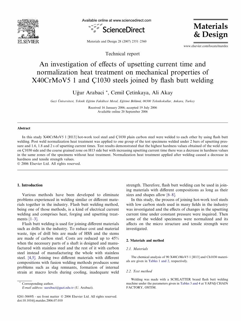
The chemical analysis of 90 X40CrMoV5 1 [H13] and Ch1030 materi-als are given in Tables 1 and 2, respectively.
2.2. Test method
Welding was made with a SCHLATTER brand flash butt weldingmachine under the parameters given in Tables 3 and 4 at YAPAS� CHAINFACTORY, OSTIM.
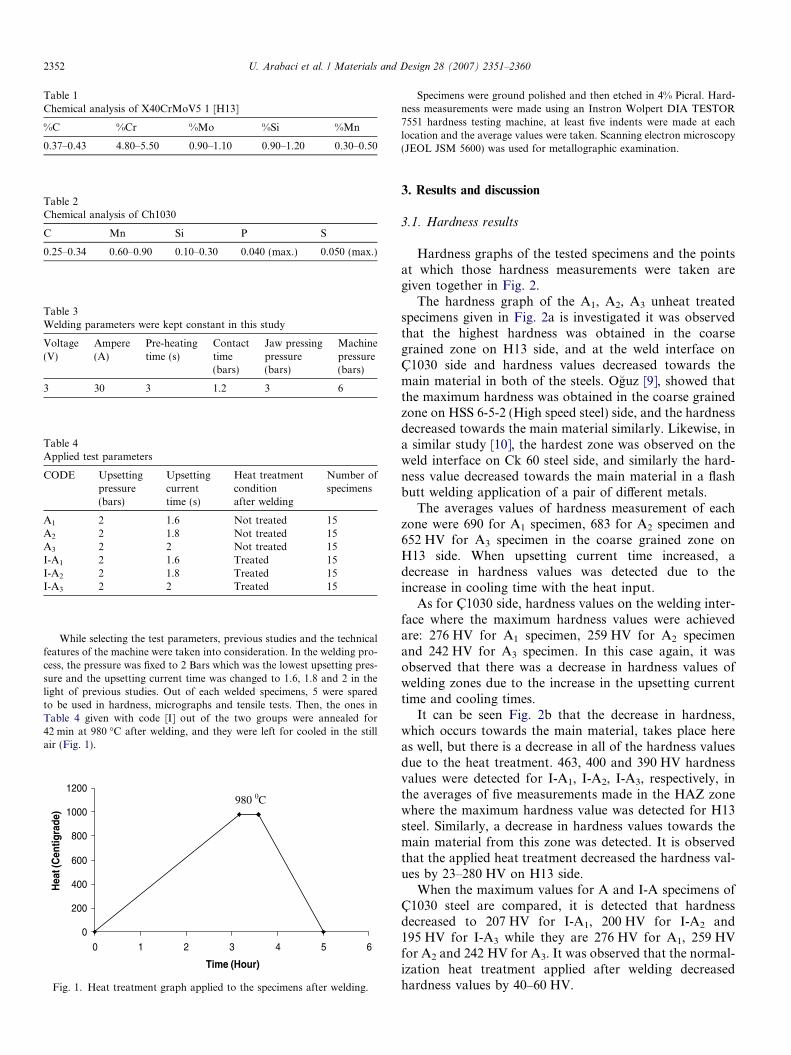
Table 1Chemical analysis of X40CrMoV5 1 [H13]
%C %Cr %Mo %Si %Mn
0.37–0.43 4.80–5.50 0.90–1.10 0.90–1.20 0.30–0.50
Table 2Chemical analysis of Ch1030
C Mn Si P S
0.25–0.34 0.60–0.90 0.10–0.30 0.040 (max.) 0.050 (max.)
Table 3Welding parameters were kept constant in this study
Voltage(V)
Ampere(A)
Pre-heatingtime (s)
Contacttime(bars)
Jaw pressingpressure(bars)
Machinepressure(bars)
3 30 3 1.2 3 6
Table 4Applied test parameters
CODE Upsettingpressure(bars)
Upsettingcurrenttime (s)
Heat treatmentconditionafter welding
Number ofspecimens
A1 2 1.6 Not treated 15A2 2 1.8 Not treated 15A3 2 2 Not treated 15I-A1 2 1.6 Treated 15I-A2 2 1.8 Treated 15I-A3 2 2 Treated 15
2352 U. Arabaci et al. / Materials and Design 28 (2007) 2351–2360
While selecting the test parameters, previous studies and the technicalfeatures of the machine were taken into consideration. In the welding pro-cess, the pressure was fixed to 2 Bars which was the lowest upsetting pres-sure and the upsetting current time was changed to 1.6, 1.8 and 2 in thelight of previous studies. Out of each welded specimens, 5 were sparedto be used in hardness, micrographs and tensile tests. Then, the ones inTable 4 given with code [I] out of the two groups were annealed for42 min at 980 �C after welding, and they were left for cooled in the stillair (Fig. 1).
0
200
400
600
800
1000
1200
0 1 2 3 4 5 6
Time (Hour)
Hea
t (C
entig
rade
)
980 0C
Fig. 1. Heat treatment graph applied to the specimens after welding.
Specimens were ground polished and then etched in 4% Picral. Hard-ness measurements were made using an Instron Wolpert DIA TESTOR7551 hardness testing machine, at least five indents were made at eachlocation and the average values were taken. Scanning electron microscopy(JEOL JSM 5600) was used for metallographic examination.
3. Results and discussion
3.1. Hardness results
Hardness graphs of the tested specimens and the pointsat which those hardness measurements were taken aregiven together in Fig. 2.
The hardness graph of the A1, A2, A3 unheat treatedspecimens given in Fig. 2a is investigated it was observedthat the highest hardness was obtained in the coarsegrained zone on H13 side, and at the weld interface onC1030 side and hardness values decreased towards themain material in both of the steels. Oguz [9], showed thatthe maximum hardness was obtained in the coarse grainedzone on HSS 6-5-2 (High speed steel) side, and the hardnessdecreased towards the main material similarly. Likewise, ina similar study [10], the hardest zone was observed on theweld interface on Ck 60 steel side, and similarly the hard-ness value decreased towards the main material in a flashbutt welding application of a pair of different metals.
The averages values of hardness measurement of eachzone were 690 for A1 specimen, 683 for A2 specimen and652 HV for A3 specimen in the coarse grained zone onH13 side. When upsetting current time increased, adecrease in hardness values was detected due to theincrease in cooling time with the heat input.
As for C1030 side, hardness values on the welding inter-face where the maximum hardness values were achievedare: 276 HV for A1 specimen, 259 HV for A2 specimenand 242 HV for A3 specimen. In this case again, it wasobserved that there was a decrease in hardness values ofwelding zones due to the increase in the upsetting currenttime and cooling times.
It can be seen Fig. 2b that the decrease in hardness,which occurs towards the main material, takes place hereas well, but there is a decrease in all of the hardness valuesdue to the heat treatment. 463, 400 and 390 HV hardnessvalues were detected for I-A1, I-A2, I-A3, respectively, inthe averages of five measurements made in the HAZ zonewhere the maximum hardness value was detected for H13steel. Similarly, a decrease in hardness values towards themain material from this zone was detected. It is observedthat the applied heat treatment decreased the hardness val-ues by 23–280 HV on H13 side.
When the maximum values for A and I-A specimens ofC1030 steel are compared, it is detected that hardnessdecreased to 207 HV for I-A1, 200 HV for I-A2 and195 HV for I-A3 while they are 276 HV for A1, 259 HVfor A2 and 242 HV for A3. It was observed that the normal-ization heat treatment applied after welding decreasedhardness values by 40–60 HV.
0
100
200
300
400
500
600
700
800
-6
a
b
-5 -4 -3 -2 -1 0 1 2 3 4 5 6
Distance from welding center (mm)
Har
dn
ess
(Vic
kers
)
A1
A2
A3
0
Lar
ge g
rain
zon
e
Lar
ge g
rain
zon
e
Tra
nsiti
on z
one
Fine
gra
in z
one
Bas
e M
etal
Fine
gra
in z
one
Bas
e M
etal
Tra
nsiti
on z
one
H13 Ç1030
Part
ly tr
ansf
orm
ed z
one
Part
ly tr
ansf
orm
ed z
one
0
100
200
300
400
500
-6 -5 -4 -3 -2 -1 0 1 2 3 4 5 6
Distance from welding center (mm)
Har
dn
ess
(Vic
kers
) I-A1
I-A2
I-A3
Fig. 2. Hardness graphs of (a) A1, A2, A3 specimens which are not heat treated, (b) I-A1, I-A2, I-A3 specimens which are normalization heat treatmentafter welding.
U. Arabaci et al. / Materials and Design 28 (2007) 2351–2360 2353
While the normalization heat treatment applied by tak-ing H13 material as reference caused an increase in hard-ness in the main material on H13 side, it caused adecrease in the main material on C1030 side. Normaliza-tion temperature of H13 (980 �C) was more than the nor-malization temperature of C1030 steel (810 �C). Thisdifference caused a decrease in hardness by causing graingrowth in C1030 steel.
3.2. Micrographs results
In this section, photos taken from the HAZ and weldingmaterial, and the effects of upsetting current time and thenormalization heat treatment applied after welding on thespecimen micrographs will be investigated.
When the micrographs of the welding zone of C1030 inFig. 3a examined, it can be seen that fair colored pearlites
were formed on the border of dark colored coarse grainedpearlites, and quite a few number of widmanstaten ferritesstretched into the pearlite grains in the weld zone. Andthe existence of a martensitic structure in the micrographsphoto of welding zone of H13 is obvious (Fig. 3b). Micro-graphs, from the coarse grained zone it is observed that fineferrite grains as well as coarse grained pearlites headed intothe widmanstaten ferrites on the grain border on C1030 side(Fig. 3c), and pearlite grains are quite few among coarse fer-rite grains in the microstructure of H13 side. When themicrographs photos of fine grained zone are examined, itcan be observed that ferrite and pearlite grains becamesmaller and did not exhibit a homogeneous distribution,and ferrites in the structure are more than the quantity ofthe pearlites on the C1030 side (Fig. 3e) and the matrixstructure on H13 side (Fig. 3f) was mainly ferrite and thecarbides are distributed throughout this matrix structure.
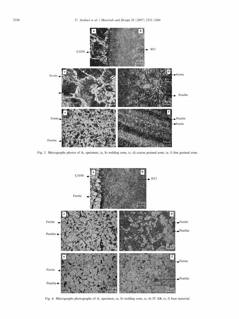
Fig. 3. Micrographs photos of A1 specimen, (a, b) welding zone, (c, d) coarse grained zone, (e, f) fine grained zone.
Fig. 4. Micrographs photographs of A1 specimen, (a, b) welding zone, (c, d) IT AB, (e, f) base material.
2354 U. Arabaci et al. / Materials and Design 28 (2007) 2351–2360
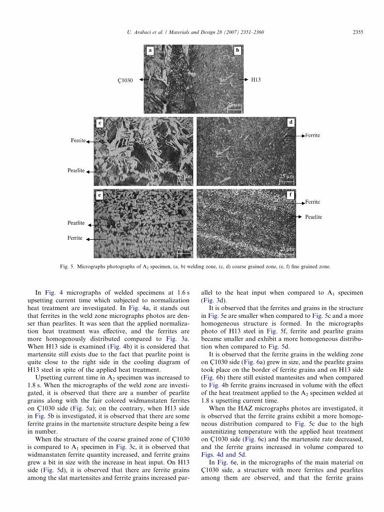
Fig. 5. Micrographs photographs of A2 specimen, (a, b) welding zone, (c, d) coarse grained zone, (e, f) fine grained zone.
U. Arabaci et al. / Materials and Design 28 (2007) 2351–2360 2355
In Fig. 4 micrographs of welded specimens at 1.6 supsetting current time which subjected to normalizationheat treatment are investigated. In Fig. 4a, it stands outthat ferrites in the weld zone micrographs photos are den-ser than pearlites. It was seen that the applied normaliza-tion heat treatment was effective, and the ferrites aremore homogenously distributed compared to Fig. 3a.When H13 side is examined (Fig. 4b) it is considered thatmartensite still exists due to the fact that pearlite point isquite close to the right side in the cooling diagram ofH13 steel in spite of the applied heat treatment.
Upsetting current time in A2 specimen was increased to1.8 s. When the micrographs of the weld zone are investi-gated, it is observed that there are a number of pearlitegrains along with the fair colored widmanstaten ferriteson C1030 side (Fig. 5a); on the contrary, when H13 sidein Fig. 5b is investigated, it is observed that there are someferrite grains in the martensite structure despite being a fewin number.
When the structure of the coarse grained zone of C1030is compared to A1 specimen in Fig. 3c, it is observed thatwidmanstaten ferrite quantity increased, and ferrite grainsgrew a bit in size with the increase in heat input. On H13side (Fig. 5d), it is observed that there are ferrite grainsamong the slat martensites and ferrite grains increased par-
allel to the heat input when compared to A1 specimen(Fig. 3d).
It is observed that the ferrites and grains in the structurein Fig. 5e are smaller when compared to Fig. 5c and a morehomogeneous structure is formed. In the micrographsphoto of H13 steel in Fig. 5f, ferrite and pearlite grainsbecame smaller and exhibit a more homogeneous distribu-tion when compared to Fig. 5d.
It is observed that the ferrite grains in the welding zoneon C1030 side (Fig. 6a) grew in size, and the pearlite grainstook place on the border of ferrite grains and on H13 side(Fig. 6b) there still existed mantesites and when comparedto Fig. 4b ferrite grains increased in volume with the effectof the heat treatment applied to the A2 specimen welded at1.8 s upsetting current time.
When the HAZ micrographs photos are investigated, itis observed that the ferrite grains exhibit a more homoge-neous distribution compared to Fig. 5c due to the highaustenitizing temperature with the applied heat treatmenton C1030 side (Fig. 6c) and the martensite rate decreased,and the ferrite grains increased in volume compared toFigs. 4d and 5d.
In Fig. 6e, in the micrographs of the main material onC1030 side, a structure with more ferrites and pearlitesamong them are observed, and that the ferrite grains
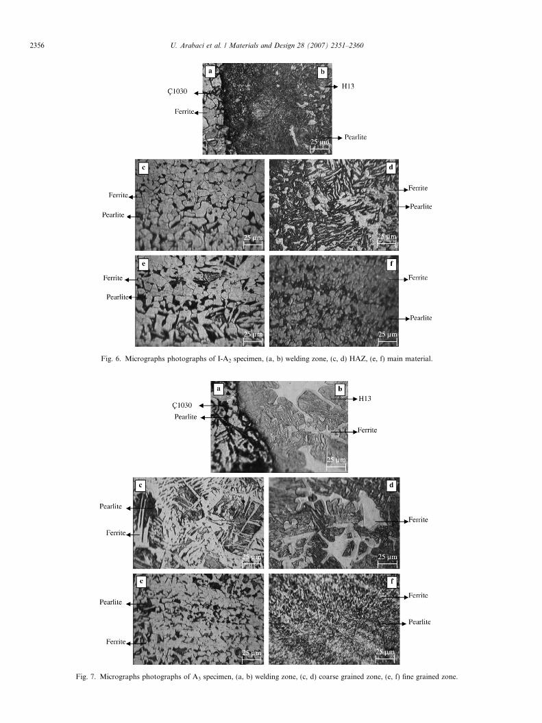
Fig. 7. Micrographs photographs of A3 specimen, (a, b) welding zone, (c, d) coarse grained zone, (e, f) fine grained zone.
Fig. 6. Micrographs photographs of I-A2 specimen, (a, b) welding zone, (c, d) HAZ, (e, f) main material.
2356 U. Arabaci et al. / Materials and Design 28 (2007) 2351–2360
U. Arabaci et al. / Materials and Design 28 (2007) 2351–2360 2357
become smaller and among them are pearlite grains whenH13 (Fig. 7f) is investigated.
As it is seen in the micrographs photo of the weldingzone of C1030 (Fig. 7a), it is observed that widmanstatenferrite quantity and volume size increased a bit by increas-ing the upsetting current time to 2 s. On H13 side (Fig. 7b)parallel to the increase in upsetting current time, ferritegrains grew and their quantity increased. Slat martensitemaintained its existence in the structure.
When the micrographs photos of the coarse grainedzone of A3 specimen is compared to the same zones of spec-imens welded at low upsetting current times, it is observedthat ferrite and widmanstaten ferrite quantity is lowered onC1030 side and likewise when H13 side in Fig. 5d is inves-tigated it is observed that ferrite quantity in the structureincreased both in volume and proportion.
In the micrographs photo of the fine grained zone ofC1030 steel in Fig. 7e, it is observed that ferrite quantityis in a big proportion and pearlites are distributed unevenlyin small quantities among the ferrite grains, and in the zonebelonging to H13 in Fig. 7f, ferrite and pearlite grains grewa bit when compared to Figs. 3f and 5f.
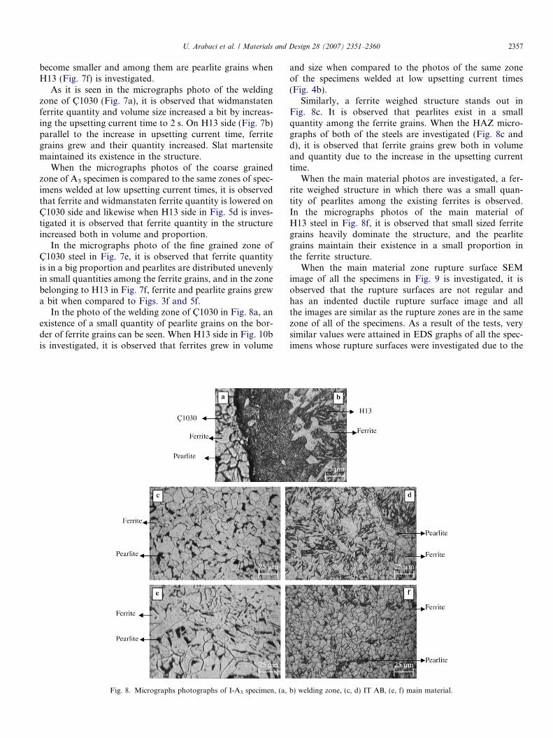
In the photo of the welding zone of C1030 in Fig. 8a, anexistence of a small quantity of pearlite grains on the bor-der of ferrite grains can be seen. When H13 side in Fig. 10bis investigated, it is observed that ferrites grew in volume
Fig. 8. Micrographs photographs of I-A3 specimen, (a,
and size when compared to the photos of the same zoneof the specimens welded at low upsetting current times(Fig. 4b).
Similarly, a ferrite weighed structure stands out inFig. 8c. It is observed that pearlites exist in a smallquantity among the ferrite grains. When the HAZ micro-graphs of both of the steels are investigated (Fig. 8c andd), it is observed that ferrite grains grew both in volumeand quantity due to the increase in the upsetting currenttime.
When the main material photos are investigated, a fer-rite weighed structure in which there was a small quan-tity of pearlites among the existing ferrites is observed.In the micrographs photos of the main material ofH13 steel in Fig. 8f, it is observed that small sized ferritegrains heavily dominate the structure, and the pearlitegrains maintain their existence in a small proportion inthe ferrite structure.
When the main material zone rupture surface SEMimage of all the specimens in Fig. 9 is investigated, it isobserved that the rupture surfaces are not regular andhas an indented ductile rupture surface image and allthe images are similar as the rupture zones are in the samezone of all of the specimens. As a result of the tests, verysimilar values were attained in EDS graphs of all the spec-imens whose rupture surfaces were investigated due to the
b) welding zone, (c, d) IT AB, (e, f) main material.
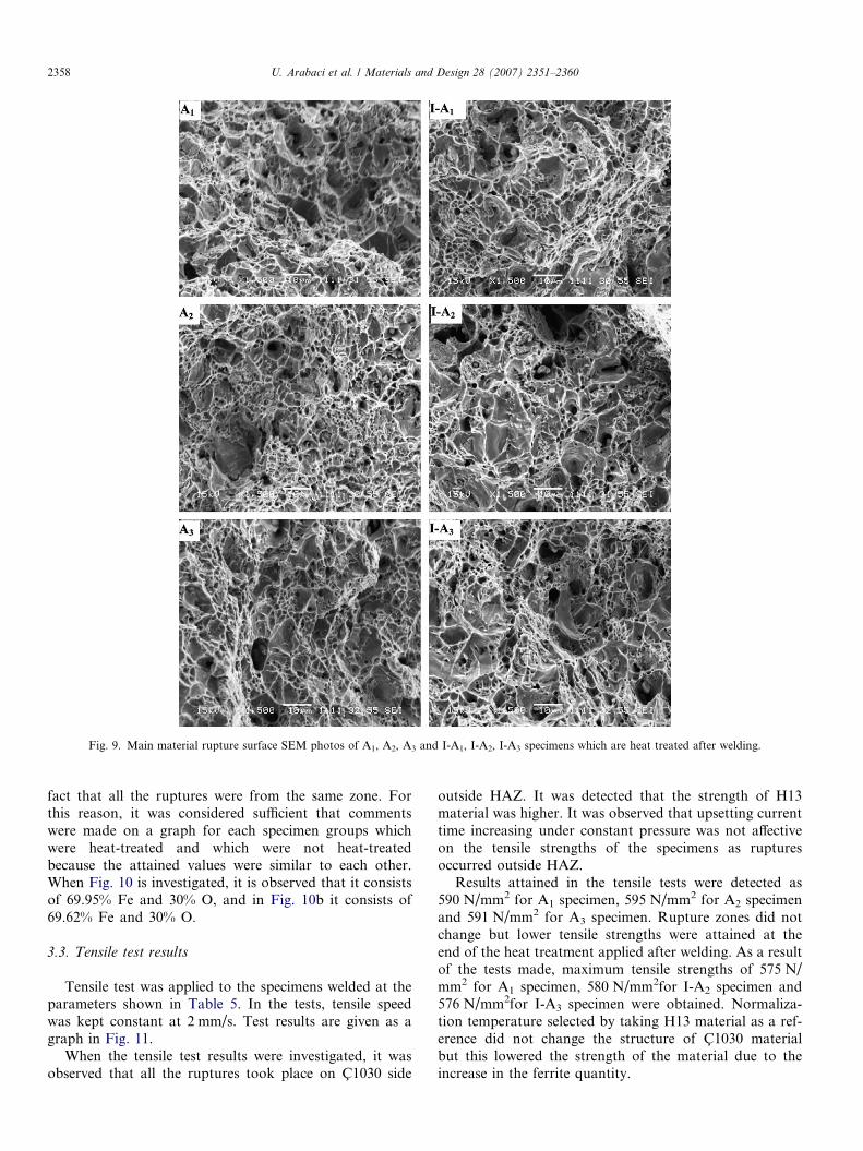
Fig. 9. Main material rupture surface SEM photos of A1, A2, A3 and I-A1, I-A2, I-A3 specimens which are heat treated after welding.
2358 U. Arabaci et al. / Materials and Design 28 (2007) 2351–2360
fact that all the ruptures were from the same zone. Forthis reason, it was considered sufficient that commentswere made on a graph for each specimen groups whichwere heat-treated and which were not heat-treatedbecause the attained values were similar to each other.When Fig. 10 is investigated, it is observed that it consistsof 69.95% Fe and 30% O, and in Fig. 10b it consists of69.62% Fe and 30% O.
3.3. Tensile test results
Tensile test was applied to the specimens welded at theparameters shown in Table 5. In the tests, tensile speedwas kept constant at 2 mm/s. Test results are given as agraph in Fig. 11.
When the tensile test results were investigated, it wasobserved that all the ruptures took place on C1030 side
outside HAZ. It was detected that the strength of H13material was higher. It was observed that upsetting currenttime increasing under constant pressure was not affectiveon the tensile strengths of the specimens as rupturesoccurred outside HAZ.
Results attained in the tensile tests were detected as590 N/mm2 for A1 specimen, 595 N/mm2 for A2 specimenand 591 N/mm2 for A3 specimen. Rupture zones did notchange but lower tensile strengths were attained at theend of the heat treatment applied after welding. As a resultof the tests made, maximum tensile strengths of 575 N/mm2 for A1 specimen, 580 N/mm2for I-A2 specimen and576 N/mm2for I-A3 specimen were obtained. Normaliza-tion temperature selected by taking H13 material as a ref-erence did not change the structure of C1030 materialbut this lowered the strength of the material due to theincrease in the ferrite quantity.
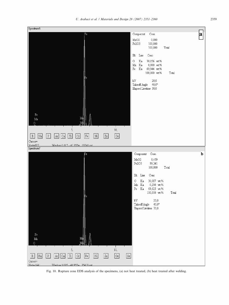
Fig. 10. Rupture zone EDS analysis of the specimens, (a) not heat treated, (b) heat treated after welding.
U. Arabaci et al. / Materials and Design 28 (2007) 2351–2360 2359
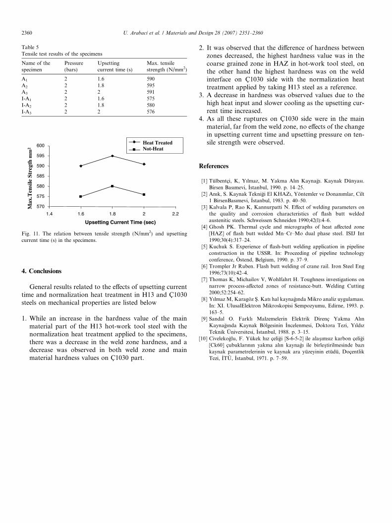
Table 5Tensile test results of the specimens
Name of thespecimen
Pressure(bars)
Upsettingcurrent time (s)
Max. tensilestrength (N/mm2)
A1 2 1.6 590A2 2 1.8 595A3 2 2 591I-A1 2 1.6 575I-A2 2 1.8 580I-A3 2 2 576
570
575
580
585
590
595
600
1.4 1.6 1.8 2 2.2
Upsetting Current Time (sec)
Heat Treated Not-Heat
Max
.Ten
sile
Str
egth
mm
2
Fig. 11. The relation between tensile strength (N/mm2) and upsettingcurrent time (s) in the specimens.
2360 U. Arabaci et al. / Materials and Design 28 (2007) 2351–2360
4. Conclusions
General results related to the effects of upsetting currenttime and normalization heat treatment in H13 and C1030steels on mechanical properties are listed below
1. While an increase in the hardness value of the mainmaterial part of the H13 hot-work tool steel with thenormalization heat treatment applied to the specimens,there was a decrease in the weld zone hardness, and adecrease was observed in both weld zone and mainmaterial hardness values on C1030 part.
2. It was observed that the difference of hardness betweenzones decreased, the highest hardness value was in thecoarse grained zone in HAZ in hot-work tool steel, onthe other hand the highest hardness was on the weldinterface on C1030 side with the normalization heattreatment applied by taking H13 steel as a reference.
3. A decrease in hardness was observed values due to thehigh heat input and slower cooling as the upsetting cur-rent time increased.
4. As all these ruptures on C1030 side were in the mainmaterial, far from the weld zone, no effects of the changein upsetting current time and upsetting pressure on ten-sile strength were observed.
References
[1] Tulbentci, K, Yılmaz, M. Yakma Alın Kaynagı. Kaynak Dunyası.Birsen Basımevi, _Istanbul, 1990. p. 14–25.
[2] Anık, S. Kaynak Teknigi El KHAZı, Yontemler ve Donanımlar, Cilt1 BirsenBasımevi, _Istanbul, 1983. p. 40–50.
[3] Kalvala P, Rao K, Kannurpatti N. Effect of welding parameters onthe quality and corrosion characteristics of flash butt weldedaustenitic steels. Schweissen Schneiden 1990;42(l):4–6.
[4] Ghosh PK. Thermal cycle and micrographs of heat affected zone[HAZ] of flash butt welded Mn–Cr–Mo dual phase steel. ISIJ Int1990;30(4):317–24.
[5] Kuchuk S. Experience of flash-butt welding application in pipelineconstruction in the USSR. In: Proceeding of pipeline technologyconference, Ostend, Belgium, 1990. p. 37–9.
[6] Trompler Jr Ruben. Flash butt welding of crane rail. Iron Steel Eng1996;73(10):42–4.
[7] Thomas K, Michailov V, Wohlfahrt H. Toughness investigations onnarrow process-affected zones of resistance-butt. Welding Cutting2000;52:254–62.
[8] Yılmaz M, Karagoz S�. Katı hal kaynagında Mikro analiz uygulaması.In: XI. UlusalElektron Mikroskopisi Sempozyumu, Edirne, 1993. p.163–5.
[9] Sandal O. Farklı Malzemelerin Elektrik Direnc Yakma AlınKaynagında Kaynak Bolgesinin _Incelenmesi, Doktora Tezi, YıldızTeknik Universitesi, _Istanbul, 1988. p. 3–15.
[10] Civelekoglu, F. Yukek hız celigi [S-6-5-2] ile alas�ımsız karbon celigi[Ck60] cubuklarının yakma alın kaynagı ile birles�tirilmesinde bazıkaynak parametrelerinin ve kaynak ara yuzeyinin etudu, DocentlikTezi, _ITU, _Istanbul, 1971. p. 7–59.