Embed Size (px)
Citation preview

Loughborough UniversityInstitutional Repository
An investigation into the useof the piezo-�uidic combinedunits as fuel injectors for
natural gas engines
This item was submitted to Loughborough University's Institutional Repositoryby the/an author.
Citation: CHEN, R. and LUCAS, G.G., 1996. An investigation into the useof the piezo-�uidic combined units as fuel injectors for natural gas engines.IN: Proceedings of SAE International Fall Fuels and Lubricants Meeting andExhibition, San Antonio, USA, 14th-17th October.
Additional Information:
• This is a conference paper [1996 c© SAE International]. It was postedon this site with permission from SAE International. Further use anddistribution of this paper requires permission from SAE International.
Metadata Record: https://dspace.lboro.ac.uk/2134/8399
Version: Published
Publisher: c© SAE International
Please cite the published version.

This item was submitted to Loughborough’s Institutional Repository (https://dspace.lboro.ac.uk/) by the author and is made available under the
following Creative Commons Licence conditions.
For the full text of this licence, please go to: http://creativecommons.org/licenses/by-nc-nd/2.5/

SA E TECHNICAL PAPER SERIES
An Investigation into the Use of Piezo-Fluidic Combined Units as Fuel
Injectors for Natural Gas Engines
RUI Chen and Gordon G Lucas Loughborough Unwers~ty of Technology
Reprinted from- Topics in Alternative Fuels and Their Emissions (SP-1208)
The Engmeer~ng Society =For Advancing Mobility and sea ~ l r and Space,
lnternatlonal Fall Fuels & Lubricants Meetlng & Exposltlon
San Antonlo, Texas October 14-17,1996
400 Commonwealth Drlve, Warrendale, PA 15096-0001 U S.A Tel: (412)776-4841 Fax (412)776-5760
Licensed to Loughborough UniversityLicensed from the SAE Digital Library Copyright 2011 SAE International
E-mailing, copying and internet posting are prohibitedDownloaded Tuesday, May 24, 2011 9:23:36 AM
Author:Gilligan-SID:13282-GUID:52221090-158.125.80.164

Theappearance of the ISSN codeatthe bottom of this page indicates SAPS consent that coptes of the paper may be made for personal or tntemal use of specficcltents Thisconsent isaivenonthe condmon however,thattheco~ier~ava$7 00 wrarbcle . . . . copy fee through the Copynght Clearance Center, Inc Operabons center, zz Rosewood Dnve, Danvers, MA01923for copylng beyond that permitted by Secbons 107 or 108 of U S Copynght Law Thts consent does not extend to other knds of copying such as copying for general distnbubon, for adverbs~ng or pmmobonal purposes, for creaang new collect~e works, or for resale
SAE roubnely stocks pnnted papers for a penod of three years following date of publ~cat~on D~rect your orders to SAE Customer Sales and Satlsfactlon Deparbnent
Quantity repnnt rates can be obmned from the Customer Sales and Sabsfacbon Department
To request permlsslon to repnnt a technrcal paper or pemlssron to usewpynghted SAE publicat~ons in other works, contact the SAE Publications Group
All SAE papers standards and selected baok are absbacted and Indexed m the Global Mobrliiy Database
No part of thts publtcabon may be reproduced in any form, in an electronic retrieval system or othervvlse, without the pnor wnnen permisston of the publisher
ISSN 014&7191 Copyrrght 1996 Society of Automotive Engineers, Inc
Positions and opinions advanced in thts paper are those of the author(s) and not necessanlv those of SAE The author 1s solelv reswnsible for the content of the . --. paper A process is available by which discussions will be pnnted with the paper if d 1s publrshed m SAE Transactrons For permlssron to publish thrs paper rn full or rn part, contact the SAE Publicattons Group
Persons wish~ng to submit papers to be considered for presentation or publication through SAE should send the manuscnpt or a 300 word abstract of a proposed manuscnpt to Secretary, Engineenng Meebngs Board, SAE
Pnnted in USA ~ 6 ~ 4 9
Licensed to Loughborough UniversityLicensed from the SAE Digital Library Copyright 2011 SAE International
E-mailing, copying and internet posting are prohibitedDownloaded Tuesday, May 24, 2011 9:23:36 AM
Author:Gilligan-SID:13282-GUID:52221090-158.125.80.164

An Investigation into the Use of Piezo-Fluidic Combined Units as Fuel
Injectors for Natural Gas Engines RUI Chen and Gordon G Lucas Loughborough Unlversily of Technology
Copynght 1996 Soclety of Auiornot~e Engmeers, Inc
ABSTRACT
A novel piezo-flm&c gaseous fuel mjector system deslgned for natural gas engmes is d e s c n i m tius paper The system consists mamly of no-movmg-part flm&c dmces and piezo electro-flm&c mterfaces The steady state and -c charactenshcs of the system were tested on a laboratory expenmental ng The results show that the system can handle the large gas volume flow rate requued by natural gas engmes and is capable of operahug vla pulse mdth modulahon A few typical commernal solenold type gas l~ectors were also tested and the results were compared wth those from the piezo-flu&c mjector system It was found that the piezo-flm&c gaseous fuel mjector system has faster mtchmg responses and smaller mjechon cycle-to- cycle ~ a ~ h o n s
INTRODUCTION
Natural gas c o w pnmanly of methane As an altername automohve fuel, natural gas can produce sgruscantly less harmful emsons However, to meet the mcreasmgly stringent velucle e m s o n legslahon, the fuel metenng system of natural gas engmes must be capable of accurate control and have a fast m t c h g response, especlaly when sto~cluometnc aulfuel raho combushon strategy mcorporated mth a *-way catalyst exhaust system is employed [I]
Gaseous fuel mjemoq combloed wtb a sophshcated engme management system, is able to provlde good mlfuel raho control [2] However, smce natural gas bas a much lower energy density and less lubnticahon than cowenllonal hqmd fuels, the gaseous fuel mjectors must, therefore, be capable of handhug the large gas volume flow rate Thus, for convenhonal solenoid type gas qectors, not only wdl the components be larger, mth lugher plntle l& than hqmd fuel injectors to aclueve a larger onfice for the
large gas volume flow rate, but they also have to work m an m o n m e n t wth poor lubncahon
In order to par'haUy overcome the low energy denslty drawback, a convenhonal soluhon for solenoid type gas lqectors is to use a hgh mjechon pressure (over 700 Wa) whch is obtamed duectly from natural gas onboard storage tank As a consequence, when tank pressure drops lower than mjechon pressure, the tank must be refuelled. Tlus leaves a part of onboard fuel unused. If the onboard natural gas is stored as compressed natural gas (CNG), h s part of unused natural gas may not affect vehcle travel range obwously smce the storage pressure is up to 20 MPa Howwer, if adsorbed natural gas (ANG) is u- the hgh q a o n pressure wdl certamly senously lumt velucle travel range smce the storage pressure is only up to 3 5 MPa 131 -
It is to meet these ddjiculhes that the development of a novel flu&c gaseous fuel mjector system based on the use of mono-stable flu&c dmces has been undertaken. Tlus system bas the potenhal of prmdmg a very accurate and fast response gas control as well as bemg able to handle large gas volume flow rates Also, tius system can be m g e d as a multl-pomt gas lqechon system and be operated wth pulse mdth modulahon mode [4,5]
One of the mportant features of the flu&c dmce is the amphficahon charactenstlc (raho of the operatmg pressure to the control pressure) It offers the posslbfity of usmg a very low energy consumphon, and very fast response piezo umt to control the flw&c devlce to mject gaseous fuel mto the engme mamfold In tlus paper d m piezo-flm&c gaseous fuel mjector system is proposed and evaluated Both steady state flow rates and dynanuc mtchmg properhes of the system were tested on a laboratory expenmental ng The test results were compared mth those from typical commemal gas mjectors It was found that the piezo-flm&c gaseous fuel mjector system bas faster mtchmg responses and smaller mjechon cycle to cycle vanallons
Licensed to Loughborough UniversityLicensed from the SAE Digital Library Copyright 2011 SAE International
E-mailing, copying and internet posting are prohibitedDownloaded Tuesday, May 24, 2011 9:23:36 AM
Author:Gilligan-SID:13282-GUID:52221090-158.125.80.164
PIEZO-FLUIDIC GASEOUS FUEL INJECTOR SYSTEM
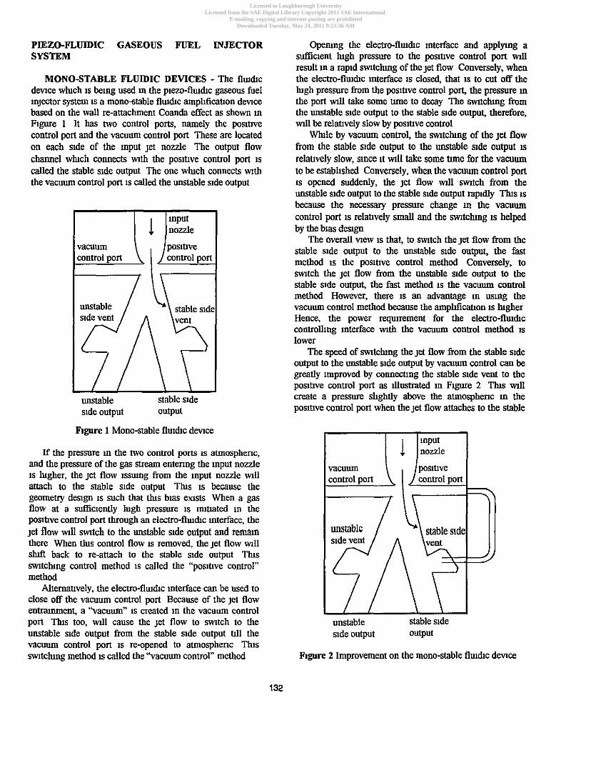
MONOSTABLE FLUIDIC DEVICES - The flmcllc dmce wluch is be~ng used m the prezo-flmcllc gaseous fuel Injector system a a mono-stable flmcllc amplfiatlon dmce based on the wall re-attachment Coanda effect as shown in Figure 1 It has two control ports, namely the posltlve control port and the vacuum control port These are located on each side of the Input jet nozzle The output flow channel wluch connects with the posrtlve control port IS
called the stable side output The one whch connects \nth the vacuum control port a called the unstable srde output
posrtlve control port control port
unstable stable srde side output output
Operung the electro-flume interface and applylug a sutficient lugh pressure to the posltlve control port \nu result m a rap~d mtclung of the jet flow Conversely, when the electro-flmcllc mterface 1s closed, that 1s to cut off the lugh pressure from the posihve control port, the pressure m the port unll take some tune to decay The m t c h g from the unstable side output to the stable s~de output, therefore, will be relatlvely slow by posmve control
a l e by vacuum control, the wtclung of the jet flow from the stable s~de output to the unstable s~de output is relatlvely slow, since it \nu take some tune for the vacuum to be estabhshed Conversely, when the vacuum control port IS opened suddenly, the jet flow d m t c h from the unstable s~de output to the stable side output rap~dly Tlus IS
because the necessary pressure change m the vacuum control port is relatlvely small and the mtchmg IS helped by the bias design
The overall vlew is that, to m t c h the jet flow from the stable srde output to the unstable side output, the fast method is the positlve control method Conversely, to m t c h the jet flow from the unstable s~de output to the stable slde output, the fast method IS the vacuum control method However, there 1s an advantage m usmg the vacuum control method because the amphficatlon 1s hlgher Hence, the power requuement for the electro-flwhc controlling mterface \nth the vacuum control method 1s lower
The speed of mtclung the jet flow from the stable side output to the unstable s~de output by vacuum control can be greatly improved by w n n m n g the stable side vent to the positlve control port as dustrated m Figure 2 Tlus wdl create a pressure slightly above the atmosphenc m the poslnve control port when the jet flow attaches to the stable
figure 1 Mono-stable flucllc dmce
If the pressure m the two control ports 1s atmosphenc, and the pressure of the gas stream entenng the input nozzle IS lugher, the jet flow isslnng from the Input nozzle wll attach to the stable slde output Tlus is because the geometry des~gn 1s such that t h ~ s b~as extsts When a gas flow at a d c i e n t l y hgh pressure is i~utlated in the posttlve control port through an electro-flume mterface, the jet flow wll w t c h to the unstable stde output and r e m n there When ths control flow IS removed, the jet flow w11 s W back to re-attach to the stable side output Tlus mtclung control method 1s called the "posrtlve control" method
Altematlvely, the electro-flu~drc Interface can be used to close off the vacuum control port Because of the jet flow entmnment, a "vacuum" 1s created In the vacuum control port Tlus too, d l cause the jet flow to w t c h to the nnstable stable side unstable side output from the stable s~de output tlll the s~de output output vacuum control port 1s re-opened to atmosphenc Tlus mtclung method is called the "vacuum control" method figure 2 Improvement on the mono-stable flmcllc d e w
Licensed to Loughborough UniversityLicensed from the SAE Digital Library Copyright 2011 SAE International
E-mailing, copying and internet posting are prohibitedDownloaded Tuesday, May 24, 2011 9:23:36 AM
Author:Gilligan-SID:13282-GUID:52221090-158.125.80.164
slde output Tlus, ln itself, wll not be hgh enough to cause the jet flow to be mtched However, ~t 1s a help when the vacuum control port 1s closed Tlus Improvement has been expenmentally proved m the prmous research [5] and was adopted m Uus work
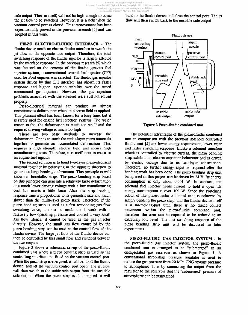
PIEZO ELECTRO-FLUIDIC INTERFACE - The flmdtc dmce needs an electro-flmdtc mterface to w t c h the jet flow to the opposlte stde output Therefore, the total m t c h n g response of the fludtc lnjector 1s largely atfected by the Interface response In the prmous research [5] wluch was focused on the concept of the flmdlc gaseous fuel mjector system, a conventlonal central fuel lnjector (CFI) used for Ford engnes was selected The flmdtc gas mjector system dnven by tlus CFI mterface has shown its faster response and hgher mnjecnon stablhty over the tested commerc~al gas mjectors However, the gas mjemon problems associated wth the soleno~d were mil not solved properly
hem-electncal matenal can produce an almost Instantaneous deformanon when an e lemc field a applled m s physrcal effect has been known for a long nme, but it 1s rarely used for engine fuel mjecnon systems The major reason 1s that the deformauon IS much too small and the reqmred dnvlng voltage IS much too lugh
There are two baslc methods to mcrease the deformanon One a to stack the muln-layer plezo matenals together to generate an accumulated deformanon Ths requues a hgh strength eleanc field and Incurs lugh manufacturing costs Therefore, 11 1s lnefficlent to use it ln an engine fuel lnjector
The second solunon 1s to bond two-layer plezoelectncal matenal together by polanslng ln the opposlte dtrmon to generate a large bendtng deformauon Tlus pnnclple 1s well known ln blmetalllc stnps The plezo benmng stnp based on Uus pnnclple can generate a relanvely large deformanon at a much lower dnvlng voltage wth a low mannfactunng cost, but exerts a little force Also, the stnp bendtng response ume IS proporuonal to its geometric sue and much slower than the mulu-layer plezo stack Therefore, d the plezo bendtng stnp IS used as a fast respondtng gas flow mtchmg valve, it must be made small, work \nth a relanvely low operanng pressure and control a very small gas flow Hence, it cannot be used as the gas lnjector duectly However, the small gas flow controlled by the plezo bendmg stnp can be used as the control flow of the flmdtc dmce The large jet flow of the flmhc devlce can then be controlled by Uus small flow and mtched between the two outputs
Flgure 3 shows a schemanc set-up of the plezo-flmdtc comblned umt where a plezo bending stnp 1s used as the controll~ng Interface and fitted on the vacuum control port When the plezo stnp 1s ener~sed, it wll bend off the fluldtc dmce, and let the vacuum control port open The jet flow wll then m t c h to the stable slde output from the unstable slde output When the plezo stnp is de-ener~sed n wll
bend to the flmdtc dmce and close the control port The jet flow wll then w t c h back to the unstable s~de output
PleZ0 controlhg mput I I [nozzle
unstable stable slde slde output output
figure 3 hezo-flmdtc comblned umt
The poteuual advantages of the plezo-flmdtc comblned w t ln companson wth the prmous solenold controlled flmdlc umt [5] are lower energy requirement, lower wear and faster m t c h n g response Unl~ke a solenold mterface whch IS controlled by electnc current, the plezo bendmg stnp exhtblts an electnc capacitor behawour and n dnven by electnc voltage due to its two-layer construction Therefore, no fnrther energy Input 1s reqwred after the henmng work has been done The plezo bendmg stnp umt belng used in tlus project can be dnven by 24 V Its energy consumpuon 1s only about 0001 W In contrast, the soleno~d fuel lnjector needs current to hold it open Its energy consumpnon a over 100 W Slnce the mtchmg actlon of the p~ezo-fluldtc comblned utut 1s aclueved by slmply bendtng the plezo stnp, and the flmdlc dmce Itself n a no-movmg-part umf there 1s no dtrect contact movement wUun the p~ezo-flmdtc comblned umf therefore the wear can be expected to be reduced to an extremely low level The fast mtchng response of the plezo bendtng stnp umt wll be discussed m later experiments
PIEZO-FLUIDIC GAS INJECTOR SYSTEM - In the p~ezo-flmdtc gas lnjector system, the plezo-flmdtc comblned umt IS arranged to be "submerged" ln an encapsulated gas reservolr as shown in Flgure 4 A conventlonal three-stage pressure regulator 1s used to reduce the gas pressure from 20 MPa CNG storage pressure to atmosphenc It IS by wnnectlng the output from the regulator to the reservolr that the "submerged pressure of atmosphenc can be miunmned
Licensed to Loughborough UniversityLicensed from the SAE Digital Library Copyright 2011 SAE International
E-mailing, copying and internet posting are prohibitedDownloaded Tuesday, May 24, 2011 9:23:36 AM
Author:Gilligan-SID:13282-GUID:52221090-158.125.80.164
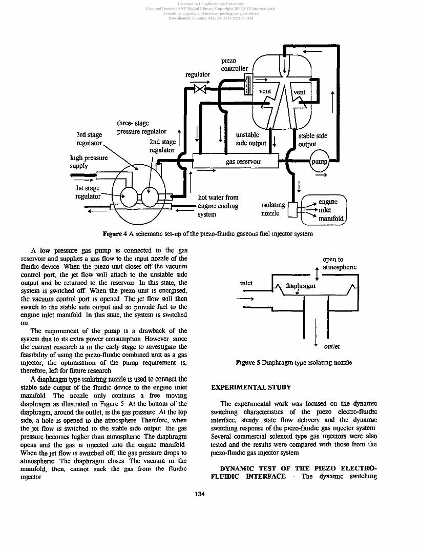
figure 4 A schemauc set-up of the plezo-flu&c gaseous fuel lnjector system
A low pressure gas pump a connected to the gas reservou and supplies a gas flow to the Input nozzle of the flu&c devlce When the plezo w t closes off the vacuum conuol port, the jet flow mll attach to the unstable s~de output and be returned to the reservolr In Uus state, the system IS mtched off When the plezo w t n energsed, the vacuum wntrol port 1s opened The jet flow ulll then m t c h to the stable s ~ d e output and so provlde fuel to the engne inlet &old In thls state, the system 1s wtched on
The requrement of the pump n a drawback of the system due to its extra power consumpuon However slnce the current research is in the early stage to lnvesugate the feaslbtllty of uslng the p~ezo-flu~dtc cornblued urut as a gas injector, the optutllsatlon of the pump reqlurement is, therefore, leff for future research
A dtaphragm type isolatmg nozzle ts used to connect the stable stde output of the flu&c dmce to the englne Inlet mamfold The nozzle only contalns a free movlng diaphragm as ~llustrated In F~gure 5 At the bottom of the dtaphragn, around the outlet, IS the gas pressure At the top side, a hole is opened to the atmosphere Therefore, when the jet flow IS mtched to the stable s~de output the gas pressure becomes hgher than atmosphenc The maphragm opens and the gas is injected Into the engnc &old When the jet flow IS wtched off, the gas pressure drops to atmosphenc The &aphragn closes The vacuum in the M o l d , then, cannot suck the gas from the flm&c lnjector
open to . atmosphenc
4 outlet
figure 5 Diaphragm type isolaung nozzle
EXPERIMENTAL STUDY
The expenmental work was focused on the dynarmc mtchmg charactensucs of the piezo electro-fludtc Interface, steady state flow debvery and the d y n m c swtchug response of the plezo-fllu&c gas Injector system Several commercial solenoid type gas Injectors were also tcstcd and the results were compared ulth those from the piezo-flmdtc gas injector system
DYNAMIC TEST OF THE PIEZO ELECTRO- FLUIDIC INTERFACE - The dynarmc mtchmg
Licensed to Loughborough UniversityLicensed from the SAE Digital Library Copyright 2011 SAE International
E-mailing, copying and internet posting are prohibitedDownloaded Tuesday, May 24, 2011 9:23:36 AM
Author:Gilligan-SID:13282-GUID:52221090-158.125.80.164

response of the piezo electro-flmhc mterface plays an imponant pan of the total sultchng response of the PICLO-
flmd~c gas Injector system It was measnred by a fast responhng Entran pressure transducer (type EPI-M4) on the laboratow test ng as shown m Figure 6
A PC based data acquslhon system was nsed to collect the test results and analyse the m t c h g responses and the cycle-tocycle m t c h g vanahons The software nsed m the PC was wnnen ur "LabVIEW', a language developed by Nahoual Instrument An Arnpllcon data acqwslhon (DAQ) board was chosen for its hlgh frequency and low cost Advanced h n h g dnver software had to be developed m order to operate the Amplicon DAQ board m the LabVIEW language sahsfactonly
outlet Figure 7 to Figure 9 show the measured pressure trace of the piezo b e n h g stnp urut and the response results from
n 500 consecuhve cycles The supply pressure at the inlet of the piezo urut was 550 Wa at whch the plezo urut can
Fagure 6 Dynarmc test ng for the piezo-flwdIc interface mtch enough gas flow to control the flmhc devlce It can
dnwng pulses
response of plezo urut (pressure transducer)
01 I I I I I I J 0 500 1000 1500 21 60
samphng number (2160=45 ms)
figure 7 Measured output pressure of the ptezo urut
average delay = 0 72 ms average delay = 0 3 1 ms standard denanon = 0 018 standard dewahon = 0 016 o 4 -r------- ------ 1 0 81i I
. . cycle number cycle number
F~gure 8 Smtclung-on response hme of the plezo nmt from F~gure 9 Smtchng-off response hme of the plezo urut from 500 cycles 500 cycles
Licensed to Loughborough UniversityLicensed from the SAE Digital Library Copyright 2011 SAE International
E-mailing, copying and internet posting are prohibitedDownloaded Tuesday, May 24, 2011 9:23:36 AM
Author:Gilligan-SID:13282-GUID:52221090-158.125.80.164

be seen that the average response ume of mtchng-on t, 1s 0 31 ms wth a standard dewauon (SD) of 0 016, and mtchng-off hf 1s 0 72 ms mth a SD of 0 018
Ftgure 10 shows the mtchng-on and -off responses of the plezo w t under viuylng supply pressure It can be seen that the mtchng-on response delay 1s very wnslstent whle mtchng-off response delay Increases sl~ghtly as supply pressure Increases The sllght Increase of the mtchng-off may due to the hgh restnchon at the outlet of the plezo umt to obtam a clear pressure trace Therefore, it 1s reasonable to predtct that both mtchng-on and -off of the plezo un~t will be more or less Independent of its supply pressure when outlet 1s opened to amb~ent
0- 350 400 450 500 550 600 650
supply pressure (kPa)
F~gure 10 Swtclung response trmes of the plezo w t
+sw Rchlng-off
0 350 400 450 500 550 600 650
supply pressure (kPa)
on and -off of the ptezo umt are h r l y wnslstent as supply pressure ~ncreases
In companson, F~gure 12 and F~gure 13 show the mtchng-on and -off responses of the premously used CFI soleno~d ~nterface The average response bme of mtchmg- on IS 1 08 ms wth SD of 0 017 and swtchng-off 1s 0 93 ms wth a SD of 0 015 The supply pressure to the soleno~d was 100 kPa whch was the opumal operauon pressure as the electro-flmdtc Interface The prevlous expenmental ffisults [5] showed that both mtchng-on and -off response umes of the CFl solenold Interface were not atfected by the control pressure
Comparing the mtchmg response tunes of the plzeo umt at 550 kPa supply pressure mth those of the soleno~d, the mtchng-on response of the piezo u~ut is over 70% faster and the mtchng-off a about 23% faster
average delay = 1 08 ms standard dematon = 0 017
5 I 2 100 200 300 400 500
cycle number
F~gure 12 Swtchng-on response trme of the CFI solenold umt from 500 cycles
average delay = 0 93 ms standard dewauon = 0 015
' O;...i w
2 6 . i l l l - 1 I... - U
- J E 08. 0 100 200 300 400 500
cycle number
F~gure 13 Swtchng-off response ume of the CFI soleno~d umt from 500 cycles
F~gure 11 Swtchng standard dewauons of the plezo w t
Flgure 11 shows the sw~tchng-on and -off mtclung stablllty of the plezo urut under varylng supply pressure It can be seen that the standard dewauons of both mtclung
STEADY STATE TEST OF THE PIEZO-FLUIDIC INJECTOR SYSTEM - The gas flow handling capabll~ty of the plezo-flmac gas Injector system was estunated by the steady state flow test operaung on a r F~gure 14 shows a
Licensed to Loughborough UniversityLicensed from the SAE Digital Library Copyright 2011 SAE International
E-mailing, copying and internet posting are prohibitedDownloaded Tuesday, May 24, 2011 9:23:36 AM
Author:Gilligan-SID:13282-GUID:52221090-158.125.80.164

regulator d
F~gure 14 Steady state test ng of the p~ezo-fluhc gaseous fuel Injector system
0 50 100 150 supply pressure (kPa)
figure 15 Steady state flow rate of the p~ezo-flwhc gas Injector system
schematic set-up of the laboratory test ng The plezo mterface was energsed dunng the test The jet flow anached to the stable s~de output and was routed to a gas flow meter through the lsolamg nozzle
F~gure 15 shows the measured steady state flow rate under varymg supply pressure of the system It can be seen that the steady state flow rate of the p~ezo-fluhc gas mjector system a linearly propomonal to the system supply pressure At 150 kPa supply pressure, the gas flow rate of
+P-Flnjector system (calcuhted) +servolet SF014 +servolet SW21 +servojet SRl51
/'
I O 5 10
injector pulse wldth (ms)
figure 16 Dynanuc flow dellvery of Sewojet mjectors and the p~ezo-fl~uhc (P-F) gas Injector system
the system 1s about 100 SLM (standard htre per uunute) Tlus flow rate 1s eqluvalent to the fuel reqwement of a 2- l~tre natural gas eugme
F~gure 16 shows the companson of the results between commerctal Servojet solenold gas Injectors and the dynanuc flow dehvery of the f luhc dmce The Servojet data were prowded by the manufacturer The dynamc flow dehvery of the p~ezo-fluhc gas Injector system was calculated from
Licensed to Loughborough UniversityLicensed from the SAE Digital Library Copyright 2011 SAE International
E-mailing, copying and internet posting are prohibitedDownloaded Tuesday, May 24, 2011 9:23:36 AM
Author:Gilligan-SID:13282-GUID:52221090-158.125.80.164
three- stage 3rd stage pesessure Iegulator
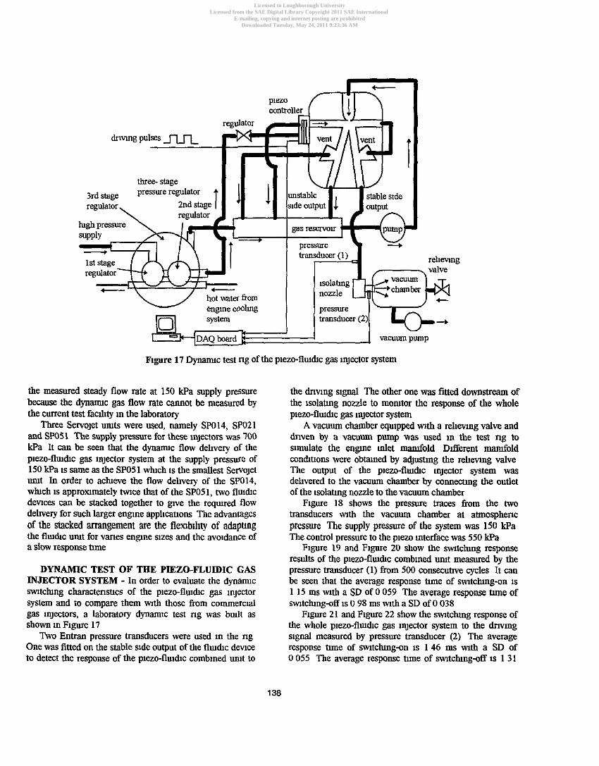
ngure 17 Dynarmc test ng of the piezo-flu&c gas lnjector system
the measured steady flow rate at 150 kPa supply pressure because the dynarmc gas flow rate cannot be measured by the current test fachty m the laboratory
Three Servojet umts were used, namely SP014, SP021 and SW51 The supply pressure for these injectors was 700 kPa It can be seen that the dynannc flow dellvery of the piezo-flm&c gas Injector system at the supply pressure of 150 kPa is same as the SP051 whch n the smallest Servojet umt In order to acheve the flow delivery of the SP014, whch a approximately twtce that of the SP051, two flru&c dev~ces can be stacked together to gve the reqmred flow dehvery for such larger engne applicahons The advantages of the stacked arrangement are the flenb~llty of adapting the flm&c urut for vanes engne slzes and the avo~dance of a slow response tune
DYNAMIC TEST OF THE PIEZO-FLUIDIC GAS INJECTOR SYSTEM - In order to evaluate the dynanuc m t c h n g charactensucs of the p~ezo-flu&c gas Injector system and to compare them wth those from commerc~al gas injectors, a laboratory dynanuc test ng was bull as shown m F~gure 17
Two Entran pressure transducers were used m the ng One was fitted on the stable s~de output of the flu&c demce to detect the response of the plezo-flmdc combined umt to
the d m n g signal The other one was fitted downmeam of the tsolatmg nozzle to monitor the response of the whole plezo-flm&c gas Injector system
A vacuum chamber eqmpped wnh a rellewng valve and dnven by a vacuum pump was used In the test ng to simulate the engne Inlet &old Different manfold con&hons were obtan~ed by adjushng the rehevmg valve The output of the piezo-flu&c injector system was dehvered to the vacuum chamber by connectmg the outlet of the lsolatmg nozzle to the vacuum chamber
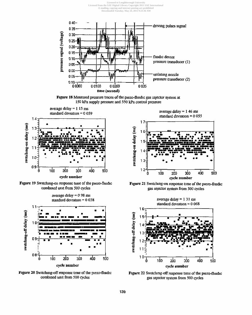
Flgure 18 shows the pressure traces from the two transducers wth the vacuum chamber at atmospheric pressure The supply pressure of the system was 150 kPa The control pressure to the plezo mterface was 550 kPa
F~gure 19 and Figure 20 show the m t c h n g response results of the p~ezo-flm&c combined umt measured by the pressure transducer (1) from 500 consecuhve cycles It can be seen that the average response ume of swtchmg-on is 1 15 ms wth a SD of 0 059 The average response tlme of wtchng-off is 0 98 ms wth a SD of 0 038
F~gure 21 and F~gure 22 show the m t c h n g response of the whole plezo-flu&c gas injector system to the d n w g slgnal measured by pressure uansducer (2) The average response tune of mtchmg-on is 146 ms with a SD of 0 055 The average response tune of swltchmg-off n 1 31
Licensed to Loughborough UniversityLicensed from the SAE Digital Library Copyright 2011 SAE International
E-mailing, copying and internet posting are prohibitedDownloaded Tuesday, May 24, 2011 9:23:36 AM
Author:Gilligan-SID:13282-GUID:52221090-158.125.80.164
d m n g pulses s~gnal
f luhc dmce pressure transducer (1)
lsolaung nozzle pressure d u c e r (2)
hme (second)
Bhgure 18 Measured pressure traces of the piezo-fluhc gas Injector system at 150 Wa supply pressure and 550 Wa control pressure
average delay = 1 15 ms standard dmauon = 0 059
1
cycle number
hgure 19 Smtchmg-on response tune of the p~ezo-flruhc comb~ned urut from 500 cycles
average delay = 0 98 ms standard denatton = 0 038
1 l - r m
.,, .'I 1 I I
B Ti. I I I -
cycle number
Rgure 20 Sw~tchmg-off response ttme of the piezo-flu&c comblned uiut from 500 cycles
average delay = 1 46 ms standard dmauon = 0 055
m 1 6!r{ . 0.0 . . • 0- ...- . - h =.-.I
I 01- rr. .rr r o r 1 5+ U r n I- U C-". 1 1rn.I. --.I - -r=.n I
a ==----YE=- 1 4 j F ! L w ! * ~ - . = ~ - * * - .
9 0.. .... 0 -.*.n - .-em.- . 9 - - . . .. r 13: * O + 2 :
12'1 I o ibo 2b0 3b0 4b0 5h0
cycle number F~gure 21 Swtchngan response ttme of the p~ezo-fluhc
gas injector system from 500 cycles
average delay = 1 3 1 ms standard dev~auon = 0 068
I
1 0 i I o ibo 2h0 3b0 4b0 5b0
cycle number
F~gure 22 Swtclnngaff response ttme of the p~ezo-flmhc gas injector system from 500 cycles
Licensed to Loughborough UniversityLicensed from the SAE Digital Library Copyright 2011 SAE International
E-mailing, copying and internet posting are prohibitedDownloaded Tuesday, May 24, 2011 9:23:36 AM
Author:Gilligan-SID:13282-GUID:52221090-158.125.80.164

ms mth a SD of 0 068 Dedumng the response tlmes of the piezo-flludc
combmed wut from those of the system, the net response tlmes of the isolatmg nozzle can be obtamed as 0 32 ms of m t c h g - o n and 0 33 ms of wtchng-off
Figure 23 and Figure 24 show the piezo-flmdc gas Injector system mtclung response tunes and lnjectlon cycle-tocycle vanabons under varying supply pressure The control pressure to the plezo Interface was 550 kPa, and the pressure of the vacuum chamber was atmospheric It can be seen that both mtclung-on and -off response bmes are fauly stable as the system supply pressure Increases Tlns feature pemts the gas flow rate through the piezo-flm&c gas mjector system also to be adjusted by varymg the supply pressure of the system
w unrt off
50 70 90 110 130 150 supply pressure (kPa)
hgure 23 Swtchng response tlmes of the p~ezo-flluhc gas injector system at varytng supply pressure
m unlt off
0
supply pressure (kPa)
I 50 70 90 110 130 150
hgure 24 Standard devlatlons of the piezo-flrudc gas mjector system at vatylng supply pressure
Figure 25 shows the system m t c h g response tlmes under different vacuum chamber pressures (absolute pressure) It can be seen, when the chamber preswe drops to vacuum, both mtclung-on and -off m t c h n g response tlmes of the system wxll shghtly increase TIus is because when the pressure m the chamber drops to vacuum, the pressure of the gas surroundmg the outlet of the isolating nozzle has to take some tlme to buld up to overcome the force acbng on the haphragm due to the sumon of vacuum However, slnce the slze of the outlet hole is small, the suction force 1s llmted Therefore, as vacuum increases, the system m t c h n g response delay wU not Increase very much
80 85 90 95 100 105 vacuum (absolute pressure kPa) -
hgure 25 S m t c h g response tlmes of the piao-flu&c gas injector system at varying outlet pressure
Flgure 26 shows the mtchmg stabil~ty of the system under varying chamber pressure It can be seen that the system mtclung stability is slightly increased when the pressure of the chamber drops to vacuum Ths, too, is due to the contnbutlon of the sumon force amng on the &aphragm
I OA k, ;o & , k l h / vacuum (absolute pressure kPa)
F~gure 26 Standard denatlorn of the piao-fllu&c gas injector system at varytng outlet pressure
Licensed to Loughborough UniversityLicensed from the SAE Digital Library Copyright 2011 SAE International
E-mailing, copying and internet posting are prohibitedDownloaded Tuesday, May 24, 2011 9:23:36 AM
Author:Gilligan-SID:13282-GUID:52221090-158.125.80.164

DYNAMIC TEST OF TBE COMMERCIAL GAS INJECTORS - The wmmernal gas mjectors avalable for wmpanson tests were three Servojet gas mjectors and one Bosch gas mjector S~nce no dynanuc charactensttcs were avalable for these propnetaq mqectors, it was dec~ded to carry out slnnlar tests on the laboratory test ng so that the~r mtclung performances wuld be wmpared wth those from the p~ezo-flmdc gas Injectton system
F~gure 27 and Figure 28 show the mtchng-on and -off responses of these soleno~d gas Injectors under varying
supply pressure It a known that the operattng pressures of these mjectors are over 700 kPa on gas engnes However, the mawmum pressure used ln the test was 350 kPa due to Ltmted peak pressure avadab~hty ID the laboratory It can be seen that the wtclung-on response tune Increases as the supply pressure Increases for all four Injectors As
menttoned earller, the m t c h g - o n response hme aclueved by the p~ezo-flmdc mnjmon system at the reqwed mnjecnon pressure of 150 kPa 1s In the regon of 146 ms Therefore, it 1s reasonable to pred~ct that the flmdc Injector has a faster mtclung-on speed than these comrnerclal gas Injectors, when equvalent quanttaes of gaseous fuel are mjected
For the mtchng-off response the Bosch urut showed the best response ttme (1 4 rns) among all the wmmerclal m t s However, the mtclung-aff response nme acluwed by the p~ezo-flu~dc Injector at 150 kPa InjectJon pressure IS 1 3 ms It should be noted that the Bosch gas mjector used here 1s a relahvely small umt des~gned for gas engnes possibly below 2 lltres capaclty Therefore, it has the advantage of a light armature and a small passage area resultmg m a faster response than the Servojet Injectors
Rgnre 27 Swtclung-on response ttmes of the commernal gas Injectors
I 0 100 m 300 supply pressure (kPa)
F~gure 29 Swtclung-on standard devlanons of the commeraal gas mjectors
I
100 200 300 4W supply pressure ( P a )
0 1m m JY) 402 supply pressure (kPa)
F~gure 28 Swtchng+ff response nmes of the wmmernal gas Injectors
Flgnre 30 Swtclung-off standard dev~auons of the wmmerclal gas xnjectors
Licensed to Loughborough UniversityLicensed from the SAE Digital Library Copyright 2011 SAE International
E-mailing, copying and internet posting are prohibitedDownloaded Tuesday, May 24, 2011 9:23:36 AM
Author:Gilligan-SID:13282-GUID:52221090-158.125.80.164
Flgure 29 and Rgure 30 show the ijechon stabdlty of these solenold Injectors It can be seen that the Bosch urut showed extremely consistent cycle-tocycle vanatlons mth a SD of 0 02 for both mtchng-on and -off delays T h s 1s largely due to its compactness and hght wetght design In companson, the m t c h n g cycle-to-cycle vanahons of the plezo-flm&c Injechon system are capable of mtchng-on mth a SD of 0 055 and mtchng-off mth a SD of 0 068
FUTURE WORK
The research reported in tlus paper has proved the poss~b~l~ty of uslng the ptezo-flmchc comblned urut as a gaseous fuel lnjector for natural gas engnes Future work d l concentrate on the evaluahon of the piezo-flm&c gaseous fuel mjechon system on a research natural gas engne, and the optlnusahon of the circulahon pump
CONCLUSIONS
(1) A novel p~ezo-flm&c gaseous fuel lnjechon svstem was proposed The system consists m n l y of the no- movtng-part flm&c devtce and the benhng stnp type plezo electro-flm&c Interface The operating pnnc~ple of the system was described and venfied by experiments on a laboratory test ng
(2) The volume flow rate of the system at 150 kPa supply pressure is eqwvalent to the Servojet SP-051 urut I-hgher flow rates can be obtiuned by staclung the mulh- layer flwchc mjector
(3) The vacuum control method of the mono-stable flm&c dmce IS ideal for gaseous fuel mnjechon due to the hgher amphficahon The m t c h n g propenes can be Improved by connecting the poslhve control port to the stable side vent
(4) The plezo electro-flulhc Interface was tested and compared mth the CFI solenoid interface It was found that the plezo urut has faster m t c h n g response speeds and much lower energy wnsumptlon
(5) The m t c h n g responses of the system at the supply pressure of 150 Wa are 1 46 ms of mtchng-on wlth a SD of 0 055, and 1 3 1 ms of mtchng-off mth a SD of 0 068
(6) Inlet mamfold vacuum d l slightly Increase the system mtchmg response delay, but decrease lnjectlon cycle to cycle vanahons
(7) Three Servojet and one Bosch commercial solenold gas mjectors were tested It was found that the p~ezo-flm&c gas Injector system at 550 Wa control pressure and 150 Wa supply pressure has faster smtchng responses than all four commernal uruts at then normal operation pressure (over 700 Wa) Also, the m t c h n g cycle to cycle vanahons of the system are smaller than all Selvqet uruts However, the Bosch urut showed a slightly better cycle to cycle swtchng repeatabihty than the piezo-flmhc gas lnjechon system
ACKNOWLEDGEMENT
The finannal support from Bnhsh Gas plc for tlus project a gratemy acknowledged The authors also msh to record their appreciahon of techmcal ass~stance prmded by Ms R Palmer and Mr A Bnghtwell, Bnhsh Gas plc , MI J Elhott, Preci-Spark Ltd UK and Techruc~an MI D Harlus and MI G Knowles, Loughborough Umverstty
REFERENCES
1 J Klimstm et al "CatalyUc Converters for Natural Gas Fuelled Engmes - A Measurement and Control Problem", SAE paper 872 165, 1987 2 M Perrault et al "An Altemahve to the Convenhonal Natural Gas Conversion Krt for Vehcles - Computer Coneolled Upstream Injemon", SAE paper 881659,1988 3 C Komodromos, S Pearson and A Gnnt, "The Potenhal of Adsorbed Natural Gas (ANG) for Advanced On-board Storage m Natural Gas-fuellled Vehcles", International Gas Research Conference (IGRC), 16-19th November 1992, Orlando, Flonda 4 R Chen, Q Huang, "Prospects for a Flmhc Dmce Based Electrowc Gas Fuel Iqechon System for Natural Gas Engnes", XXV FISITA Congress, 17-21 October 1994, Beljlng 5 R Chen, Q Huang, "An Invesbgauon Into the Use of Flmhc Dmces as Gas Fuel Injectors for Natural Gas Engnes", SAE paper 960768,1996
Licensed to Loughborough UniversityLicensed from the SAE Digital Library Copyright 2011 SAE International
E-mailing, copying and internet posting are prohibitedDownloaded Tuesday, May 24, 2011 9:23:36 AM
Author:Gilligan-SID:13282-GUID:52221090-158.125.80.164