Embed Size (px)
Citation preview

An investigation into the face sheet (skins) debonding of glass balsa sandwich
composites
Comptest Lausanne 02/2011Dr M. Colin de Verdiere ([email protected])
Professor J.M Dulieu - Barton, Professor R.A Shenoi and Dr J.I.R Blake
Content• Introduction.
• Manufacture of specimens.
• Material and crack characteristics.
• Testing for debonding characterisation.
• Experimental results.
• Digital image correlation for added material
information.
• Parameters estimation.
• Conclusion.
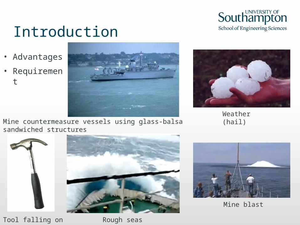
Introduction
• Advantages
• Requirement
Mine blast
Mine countermeasure vessels using glass-balsa sandwiched structures
Weather (hail)
Tool falling on deck
Rough seas

Variability of balsa wood
Defects (gaps in between blocks)
Each blocks has different mechanical properties
End grain balsa sheets are made of many different blocks
Balsa core coated in resin and drying in oven to avoid excessive resin
absorption

Specimen manufacture
Large panel
Reduced panel
Crack film Crack film
Sp
eci
men
1
Sp
eci
men
2
Sp
eci
men
3
Sp
eci
men
4
Sp
eci
men
5
Sp
eci
men
6
Sp
eci
men
7
Sp
eci
men
8
Sp
eci
men
9
Sp
eci
men
1
0
Sp
eci
men
1
1
Sp
eci
men
12
Sp
eci
men
13
Sp
eci
men
1
Sp
eci
men
2
Sp
eci
men
3
Sp
eci
men
4
Sp
eci
men
5
Sp
eci
men
6
Sp
eci
men
7
Sp
eci
men
8
Sp
eci
men
9
Sp
eci
men
1
0
Sp
eci
men
1
1
Sp
eci
men
14
Sp
eci
men
15
Sp
eci
men
1
6
Sp
eci
men
1
7
Sp
eci
men
1
8
Sp
eci
men
19
Sp
eci
men
20
Sp
eci
men
21
Sp
eci
men
22
Sp
eci
men
23
Sp
eci
men
2
4
Sp
eci
men
25
Sp
eci
men
26

Specimen manufacture
Vacuum bagFlow mediaPeel plyDBL 800CSM Mat
• CSM Mat• DBL 800• Peel ply• Flow media• Mould
Balsa coreCrack film

Specimen characteristics
Face sheet (skin)
Core
Face sheet (skin)
Pre crack area
Width: 35 mmCrack length: 50 mmLength: 200mmCore thickness: 13-40mmFace sheet (skins) thickness: 4 mm
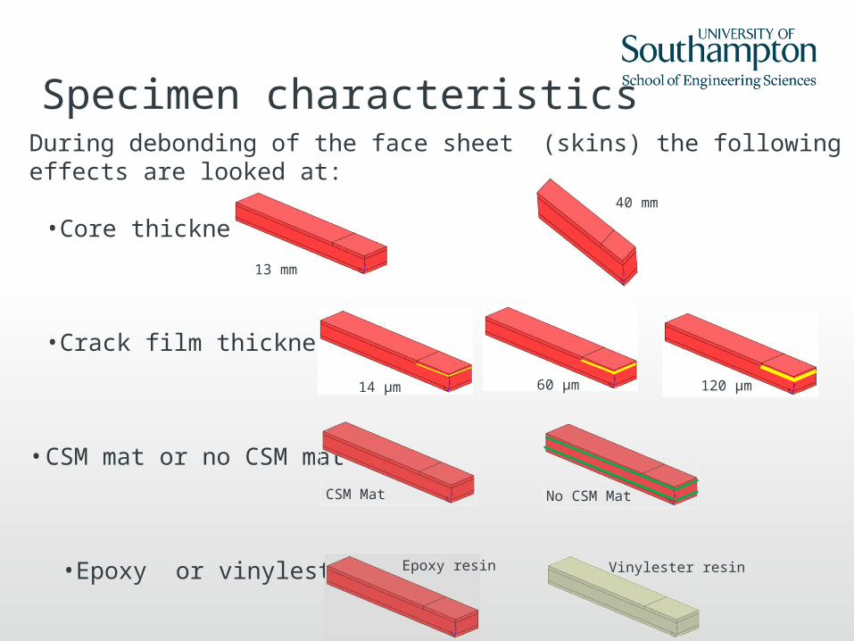
Specimen characteristicsDuring debonding of the face sheet (skins) the following effects are looked at:
•Core thickness
•Crack film thickness
• CSM mat or no CSM mat
•Epoxy or vinylester resin
13 mm
40 mm
14 μm 60 μm 120 μm
CSM Mat No CSM Mat
Epoxy resin Vinylester resin
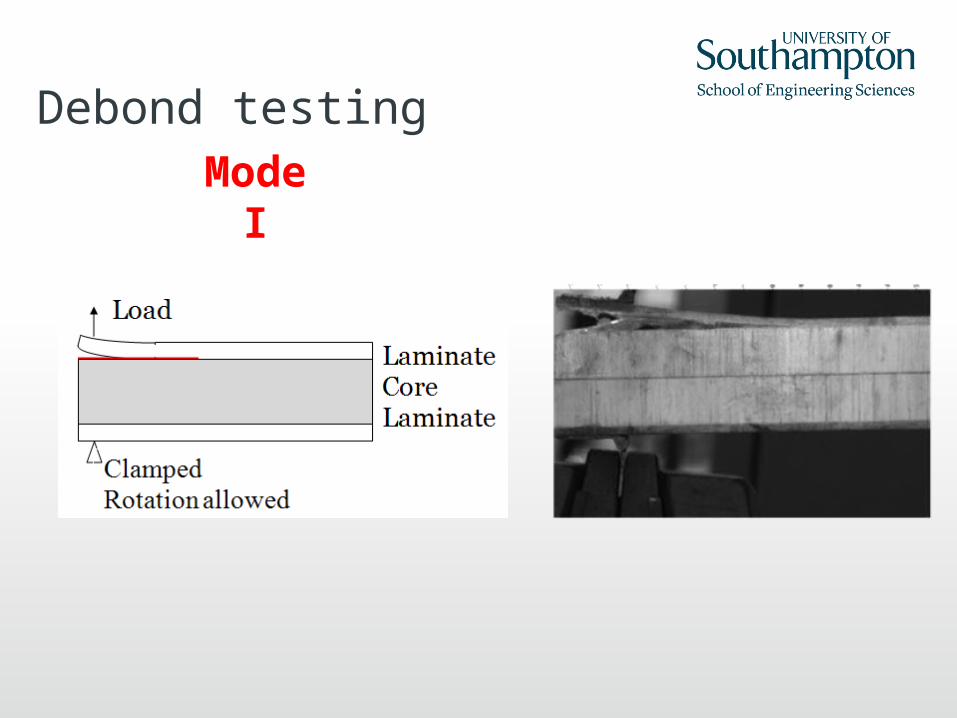
Debond testingMode I

Debonding of epoxy
specimenMode I (14μm crack film, core thickness 13 mm, Mat CSM)
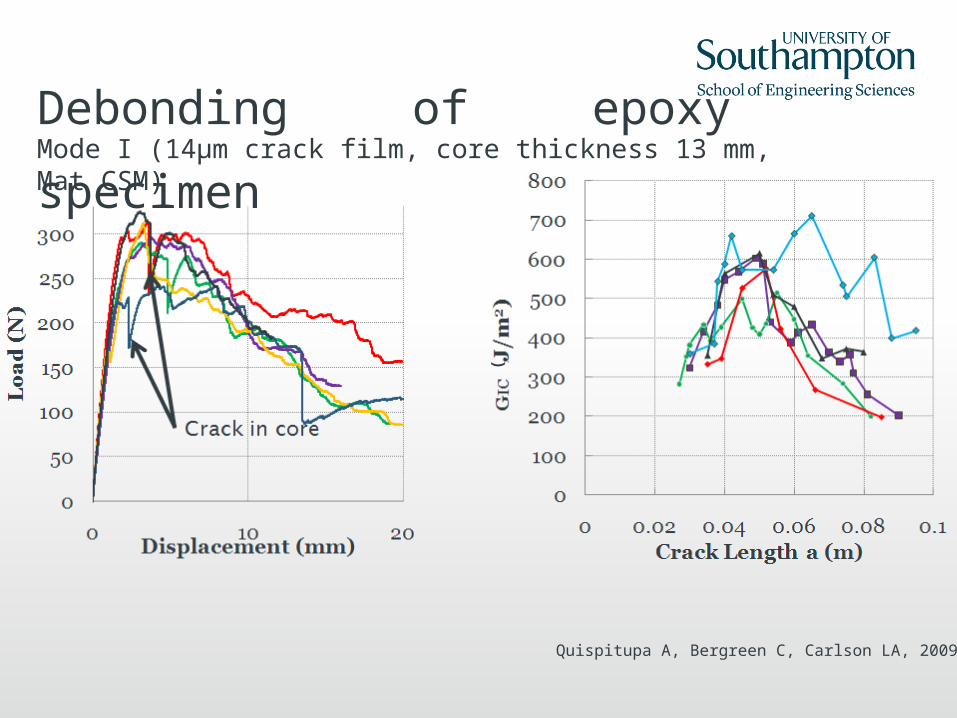
Debonding of epoxy
specimenMode I (14μm crack film, core thickness 13 mm, Mat CSM)
(
Quispitupa A, Bergreen C, Carlson LA, 2009

Debonding of epoxy specimenEffect of core thickness (14μm crack film, core thickness 40 mm, Mat CSM)
Two different modes of failure depending on the specimen position in the panel: interface or wood crack propagation (just
below interface)
Interface crack propagation
Balsa cracks propagation

Debonding of epoxy specimenEffect of crack film thickness (60-120 μm crack films, core thickness 13 mm, Mat CSM)Crack film thickness 60
μmCrack film thickness 120 μm
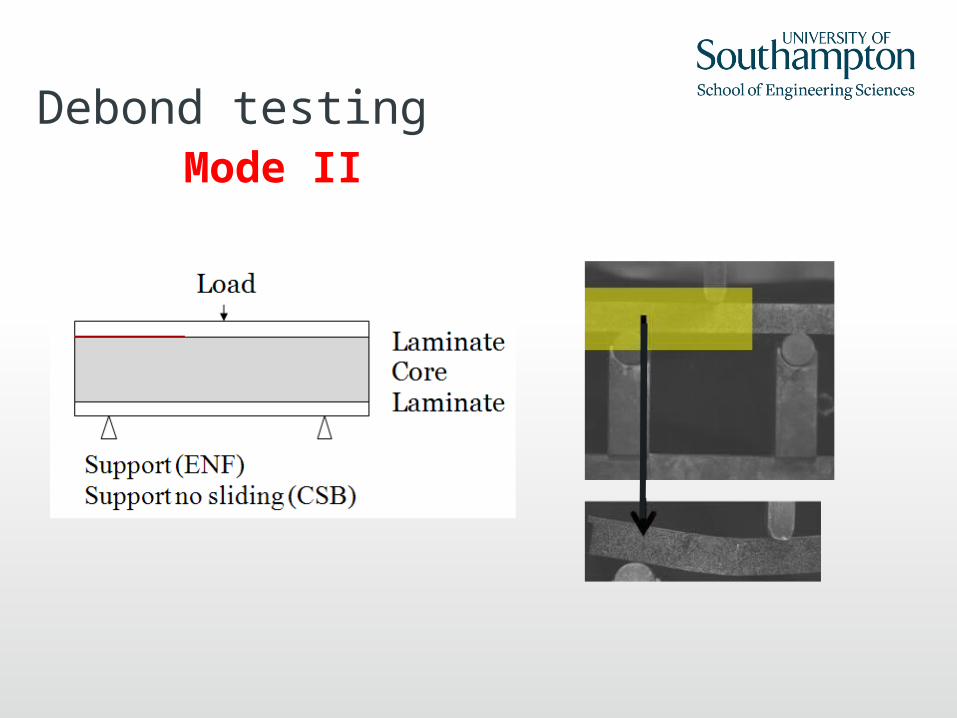
Mode IIDebond testing

Debonding of epoxy
specimenMode II (14μm crack film, core thickness 13 mm)
No mat CSM
Mat CSM
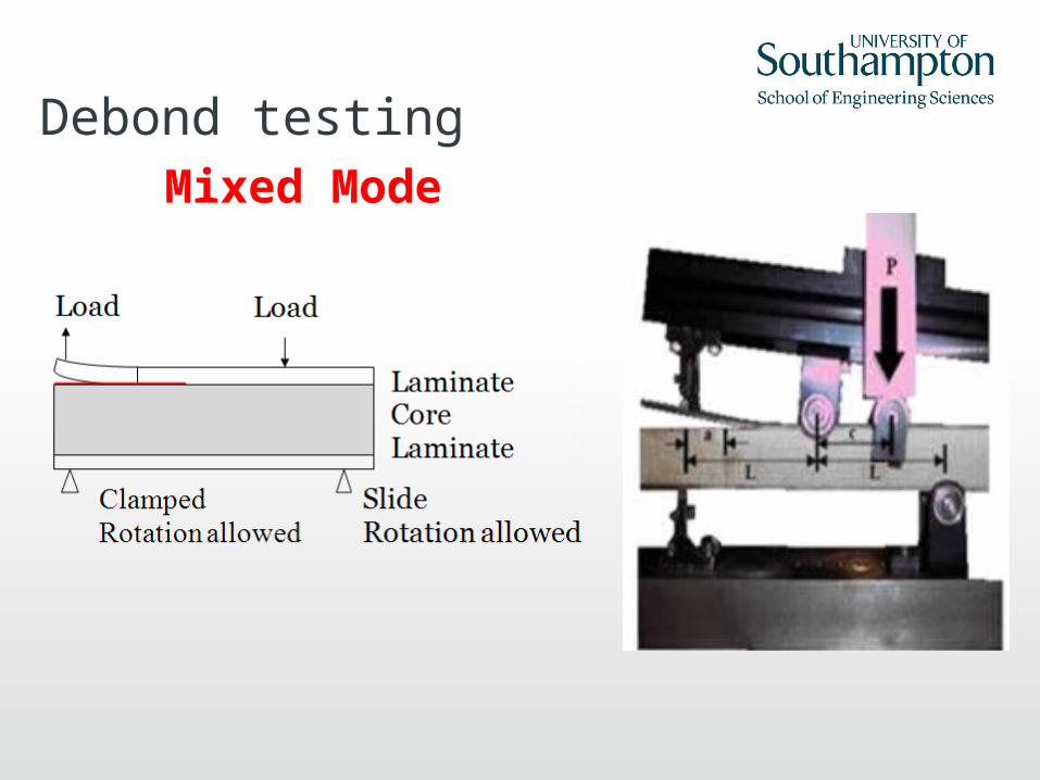
Mixed Mode
Debond testing

Debonding of epoxy
specimenMixed Mode (14μm crack film, core thickness 13 mm,
Mat CSM)
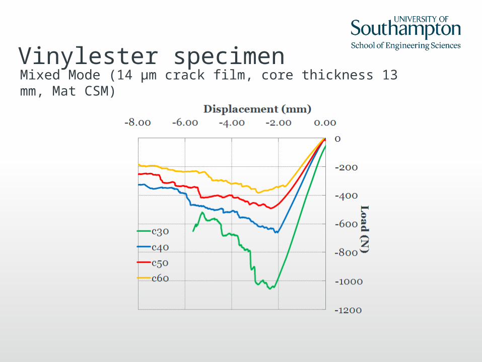
Vinylester specimenMixed Mode (14 μm crack film, core thickness 13 mm, Mat CSM)

Epoxy – vinylester
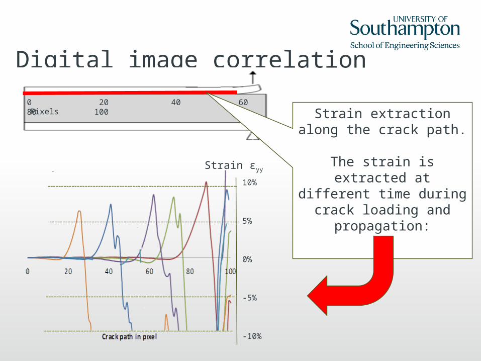
Digital image correlation
Strain versus crack path through time0 20 40 60 80 100
Strain extraction along the crack path.
The strain is extracted at different time during
crack loading and propagation:
Pixels
10%
5%
0%
-5%
-10%
Strain εyy

Parameter estimation- Face sheet and core stiffness
- Stress at which the crack propagate in Mode I and II
- G strain release energy rate in Mode I and II
F (N)
d (mm)
σ : Stress to propagate the crack
G
Conclusion
•Variability of balsa wood is important
•Thicker core specimens provided less reproducible results and lower GIC.
•Thick crack film led to unsteady crack tip initiation and propagation and
should be avoided.
•The presence of mat layer is beneficial.
•Vinylester resin was weaker than epoxy resin in mix mode loading.
•GIC computed by recording of the crack tip location during loading.
•GMMB calculation scatter due to the difficulty to locate the crack.
•Mode II crack location was not detectable precisely to the naked eyes.
• To improve this reading usage of digital image correlation may help to refine the crack location.
Future work
• Validation of the optical crack location method in Mode I and usage in Mode II for GIIC calculation.
• Refinement of materials parameters
• Numerical validation in Mode I, II and mix mode and comparison to experimental results.

Thank you


![arXiv:2004.01415v2 [hep-ph] 7 May 2020 Matter (DM ...E-mail: mariana.frank@concordia.ca, Y.Hicyilmaz@soton.ac.uk, S.Moretti@soton.ac.uk, ozerozdal@gmail.com Abstract: We test E 6 realisations](https://img.pdfslide.us/doc/110x75/5ff8f3456aa11f0aed57b3a3/arxiv200401415v2-hep-ph-7-may-2020-matter-dm-e-mail-concordiaca-yhicyilmazsotonacuk.jpg)