Embed Size (px)
Citation preview
Robert TremblayPolytechnique Montreal, Canada
An Inverted V-Braced Frame System Exhibiting Bilinear Response
for Seismic Stability underLong Duration Subduction Earthquakes

Overview
• Steel SFRSs
• Seismic stability
• Cascadia subduction earthquakes
• Canadian code provisions
• Seismic stability of an 16-storey braced frame
• Column continuity
• Proposed chevron braced frame
• Conclusions
Robert Tremblay, Polytechnique Montreal, Canada 3
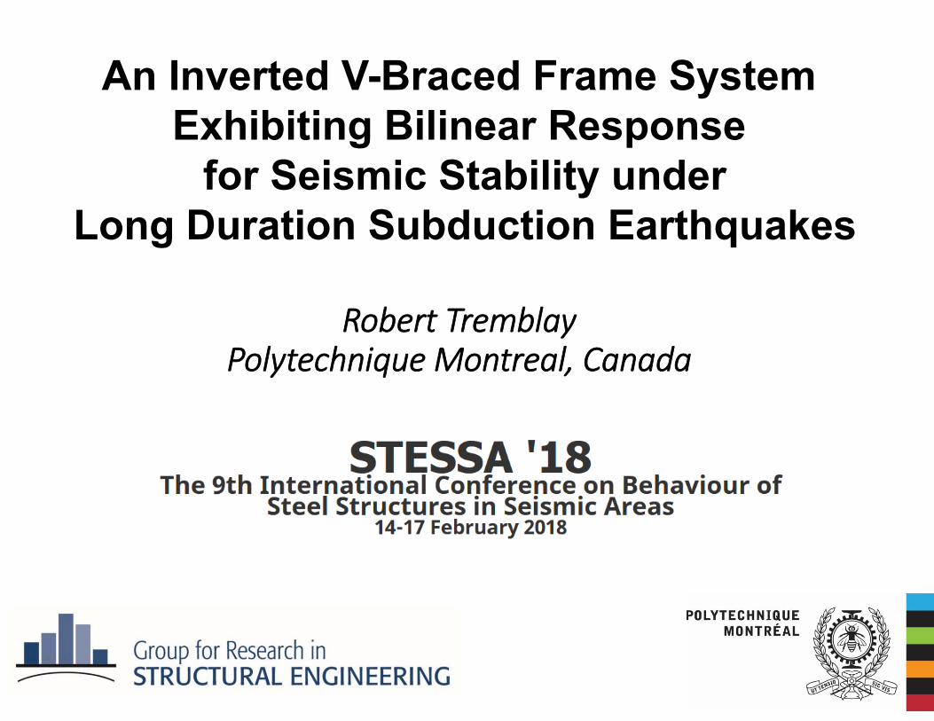
Plastic Hinge (typ.)
Shearyielding
Plastic Hinge (typ.)
Tensionyielding
Plastic HingeTension
yielding
Tensionyielding
Compressionyielding e
Plastic Hinge (typ.)
Plastic Hinge
End-plateBending
Shearyielding
Current Steel SFRSs
CBF BRBF EBF
MRF PW
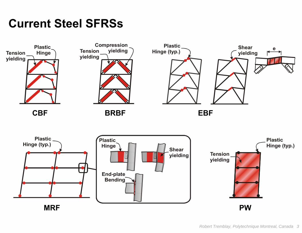
Main achievements
• Systems have reliable energy dissipation
through robust ductile response
• Comprehensive design provisions to achieve
this energy dissipation capacity and allow
reduced design seismic forces
• Structural damage confined to a limited
portion of the structure to minimize repair
Robert Tremblay, Polytechnique Montreal, Canada 4
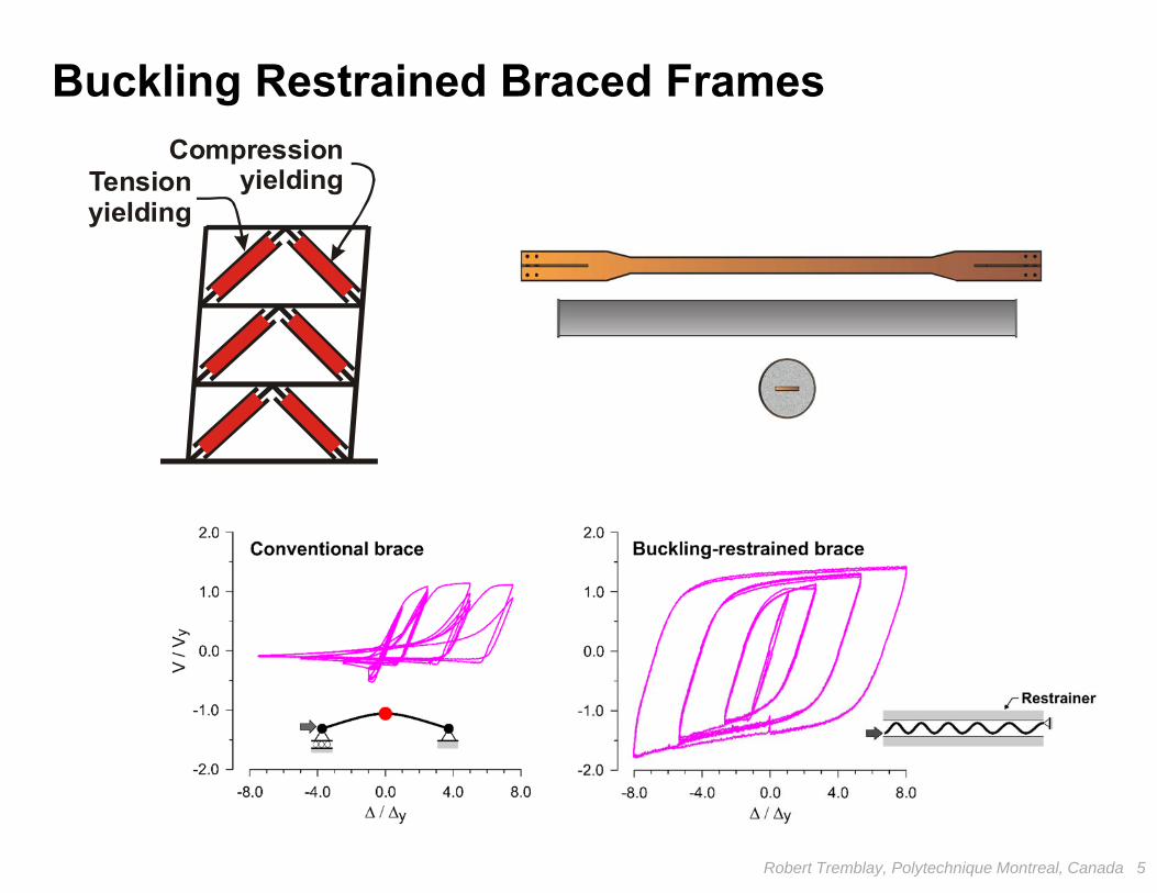
Tensionyielding
Compressionyielding
Buckling Restrained Braced Frames
Robert Tremblay, Polytechnique Montreal, Canada 5
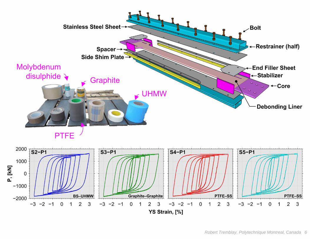
Graphite
Molybdenum disulphide
UHMW
PTFE
Robert Tremblay, Polytechnique Montreal, Canada 6

Eccentrically Braced Steel FramesShearyielding
e
Use of Modular Links
with N. Mansour& C. Christopoulos, University of Toronto
Robert Tremblay, Polytechnique Montreal, Canada 7
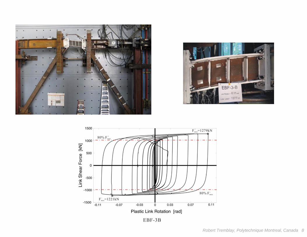
Robert Tremblay, Polytechnique Montreal, Canada 8
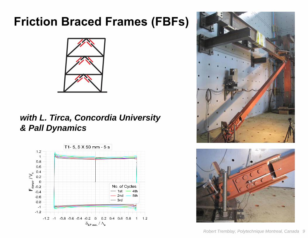
with L. Tirca, Concordia University& Pall Dynamics
Robert Tremblay, Polytechnique Montreal, Canada 9
Friction Braced Frames (FBFs)
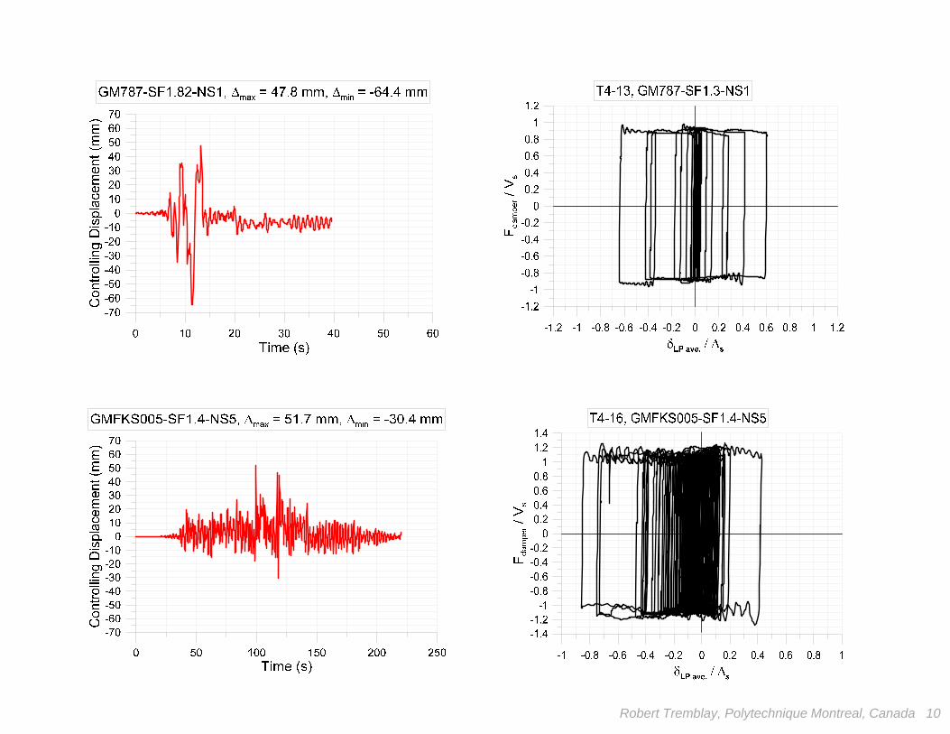
Robert Tremblay, Polytechnique Montreal, Canada 10
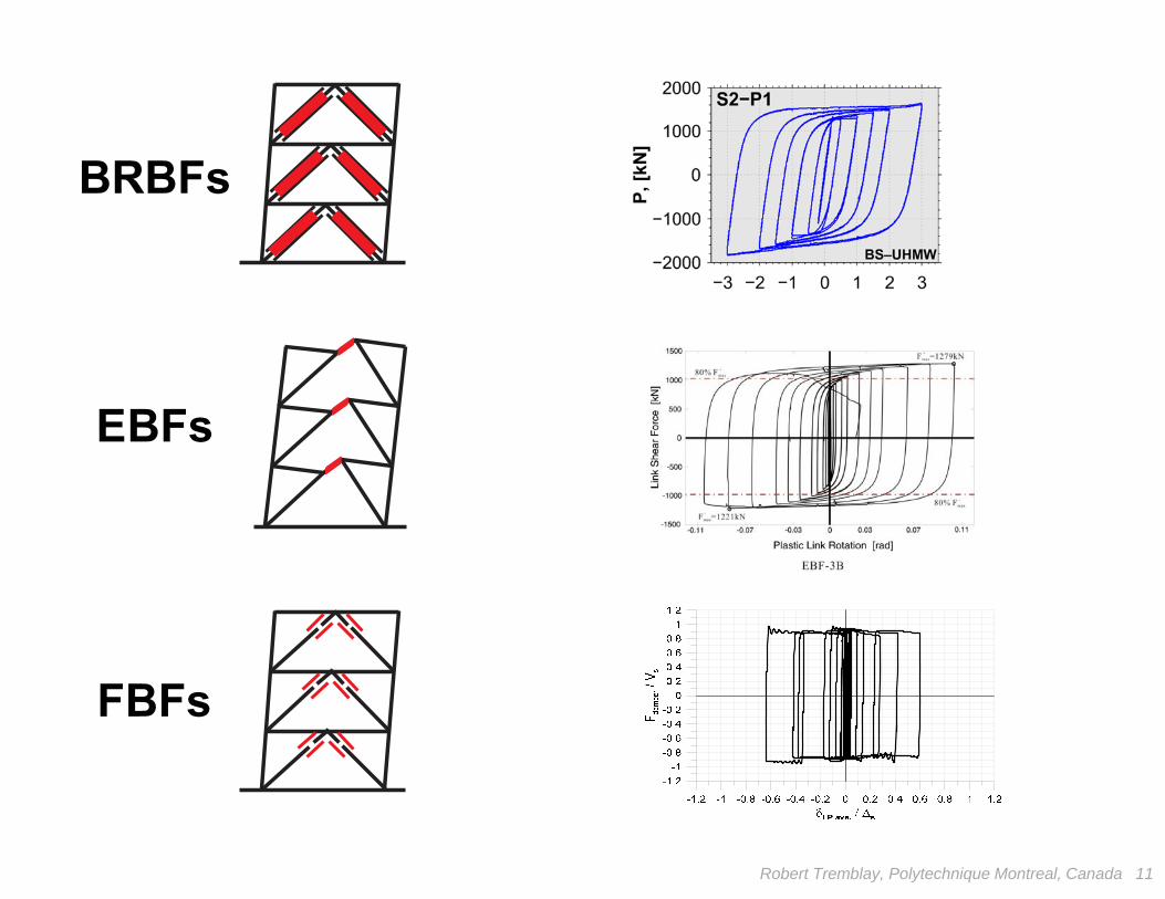
BRBFs
FBFs
EBFs
Robert Tremblay, Polytechnique Montreal, Canada 11
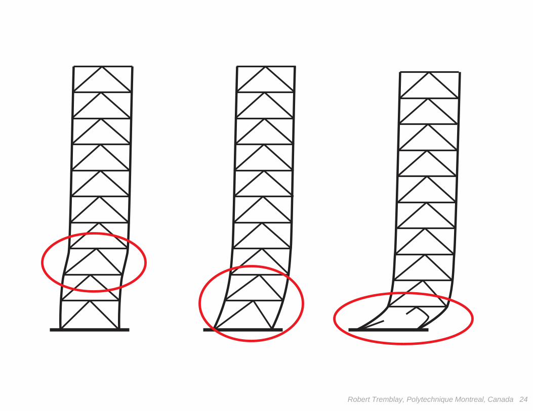
Main Shortcomings
• Residual deformations
• Prone to soft-storey response
and dynamic instability
Robert Tremblay, Polytechnique Montreal, Canada 12
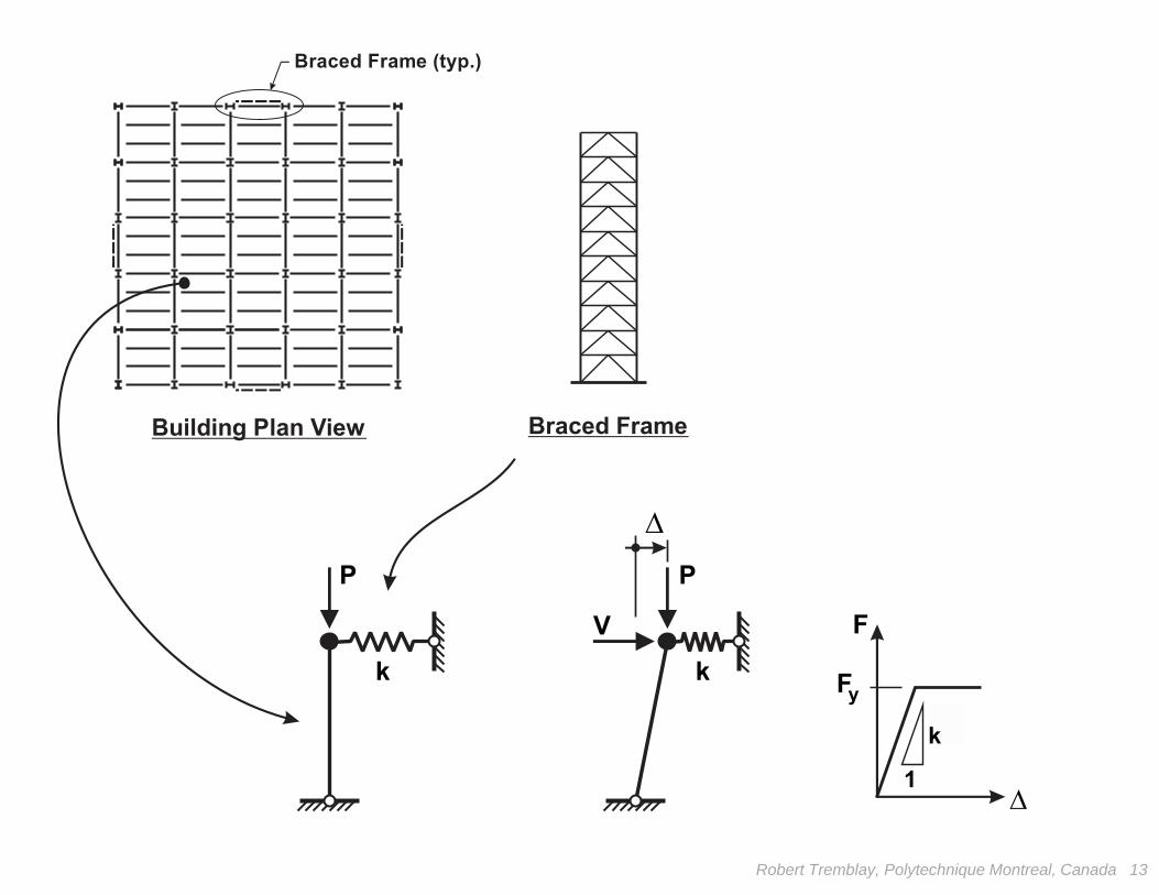
Braced Frame (typ.)
Braced FrameBuilding Plan View
F
F yk
1
V
PP
kk
Robert Tremblay, Polytechnique Montreal, Canada 13
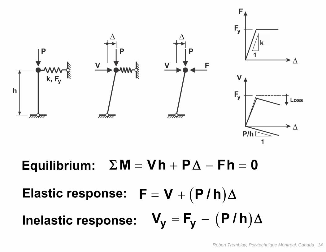
Robert Tremblay, Polytechnique Montreal, Canada 14
M Vh P Fh 0
k, Fy
F
F yk
1
1
V
LossF y
V V
P P
P/h
P
F
h
Equilibrium:
Elastic response:
Inelastic response:
F V P / h
y yV F P / h

k, FW
y
F
Fy
k
1
P
h
Robert Tremblay, Polytechnique Montreal, Canada 15
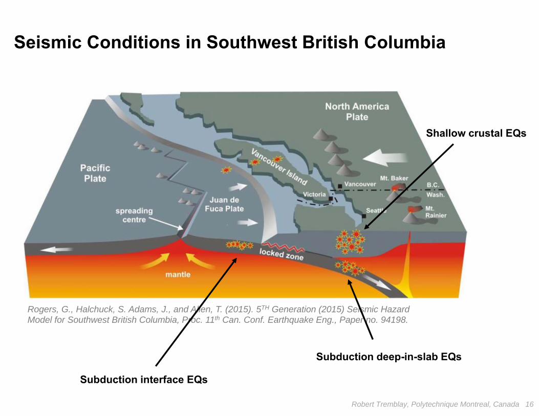
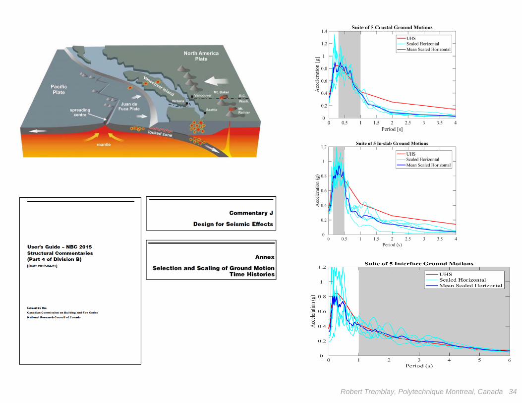
Seismic Conditions in Southwest British Columbia
Rogers, G., Halchuck, S. Adams, J., and Allen, T. (2015). 5TH Generation (2015) Seismic Hazard Model for Southwest British Columbia, Proc. 11th Can. Conf. Earthquake Eng., Paper no. 94198.
Subduction deep-in-slab EQs
Subduction interface EQs
Shallow crustal EQs
Robert Tremblay, Polytechnique Montreal, Canada 16
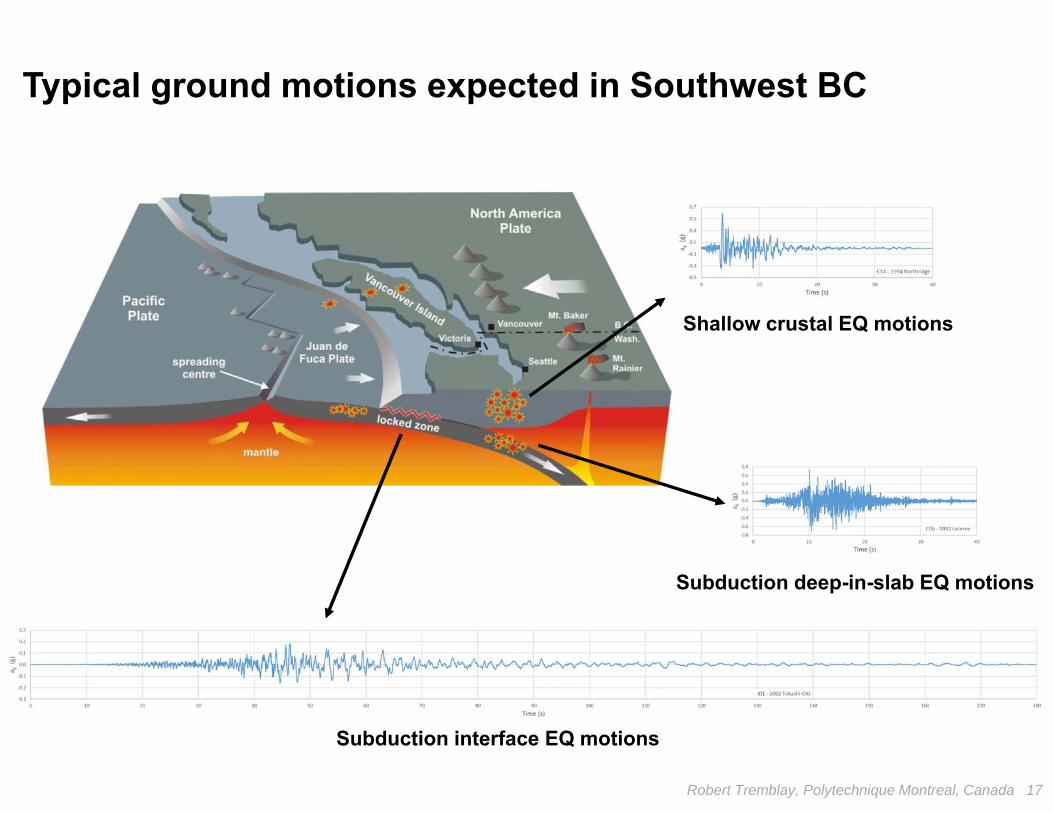
Typical ground motions expected in Southwest BC
Subduction deep-in-slab EQ motions
Subduction interface EQ motions
Shallow crustal EQ motions
Robert Tremblay, Polytechnique Montreal, Canada 17
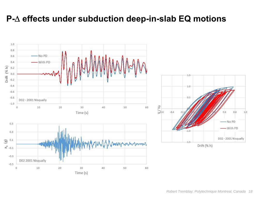
P- effects under subduction deep-in-slab EQ motions
Robert Tremblay, Polytechnique Montreal, Canada 18
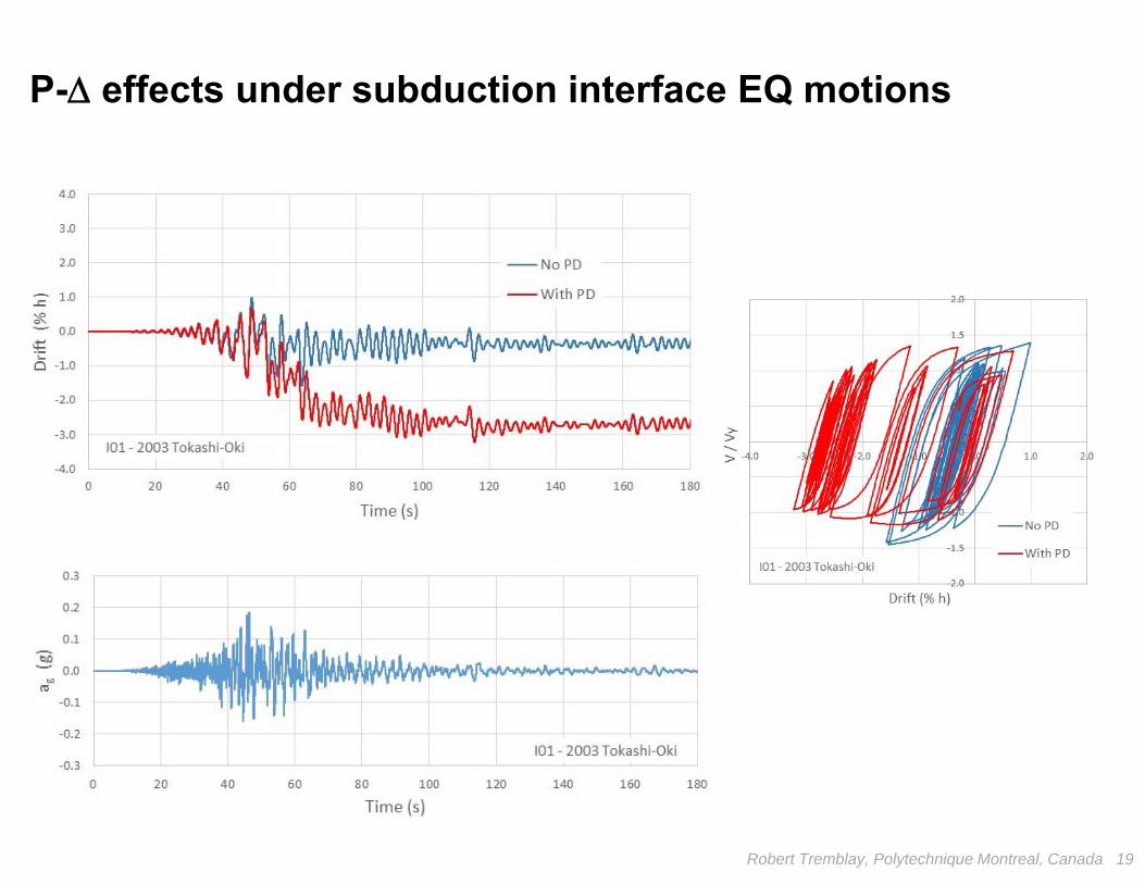
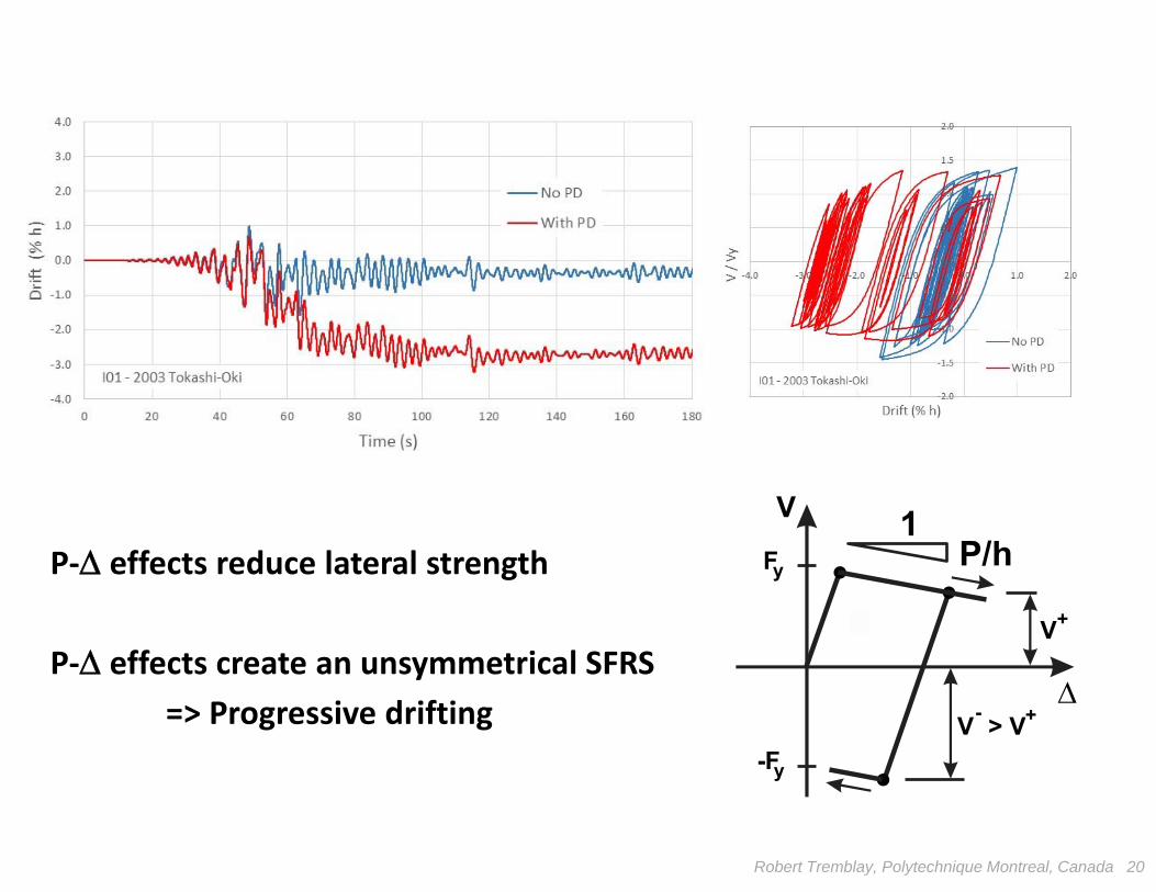
P- effects under subduction interface EQ motions
Robert Tremblay, Polytechnique Montreal, Canada 19
Robert Tremblay, Polytechnique Montreal, Canada 20
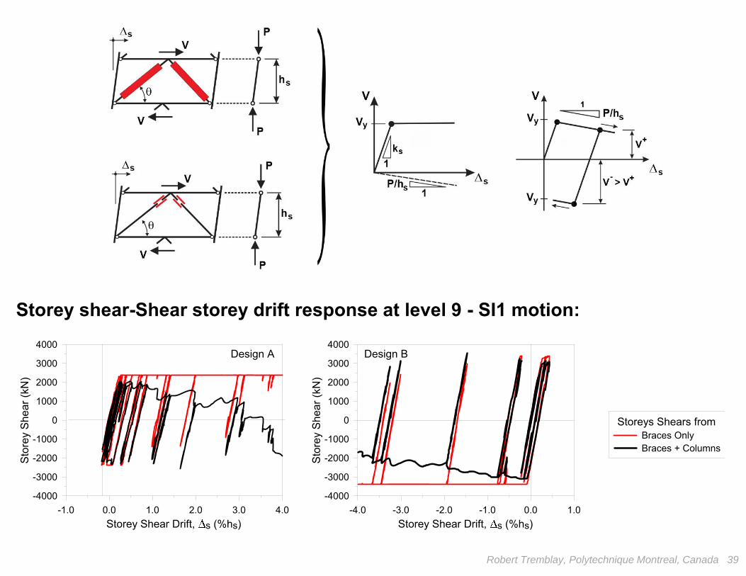
P‐ effects reduce lateral strength
P‐ effects create an unsymmetrical SFRS=> Progressive drifting
F
-F
V+
+-V > V
y
y
V 1P/h
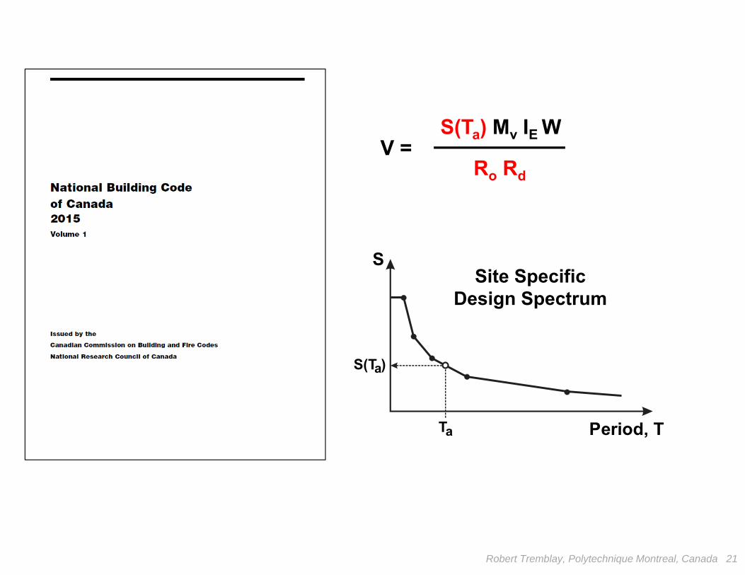
V =S(Ta) Mv IE W
Ro Rd
S
S(T )
Period, TTa
a
Site SpecificDesign Spectrum
Robert Tremblay, Polytechnique Montreal, Canada 21
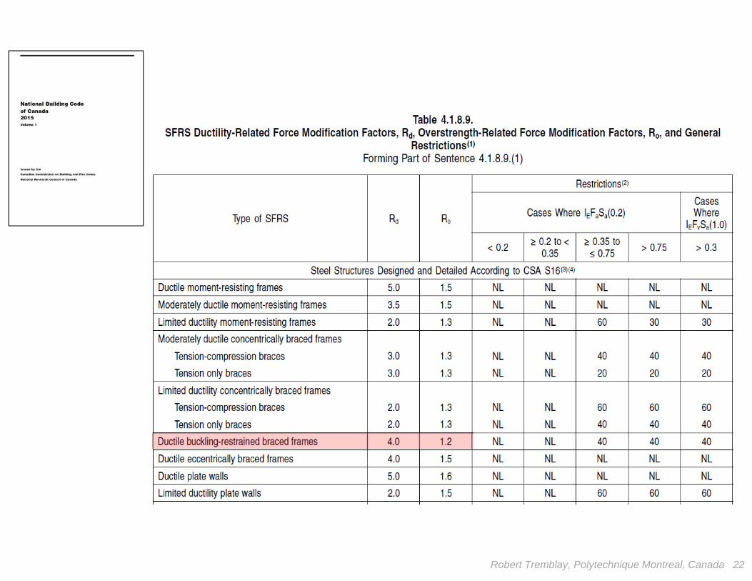
Robert Tremblay, Polytechnique Montreal, Canada 22

RdRo = 4.8
RdRo = 7.5
V =S(Ta) Mv IE W
Ro Rd
k, FW
y
P
aT = 1.8 s
Victoria, BCFirm Ground
Robert Tremblay, Polytechnique Montreal, Canada 23
Robert Tremblay, Polytechnique Montreal, Canada 24
Robert Tremblay, Polytechnique Montreal, Canada 25
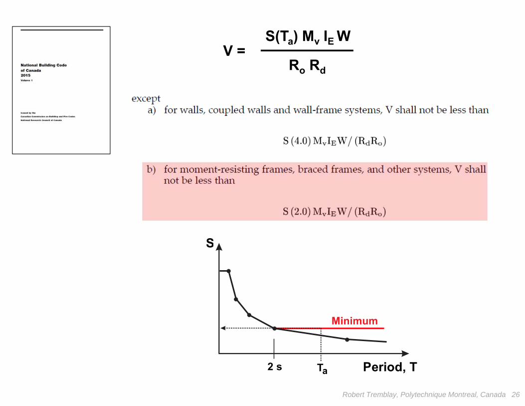
V =S(Ta) Mv IE W
Ro Rd
S
Period, T
Minimum
2 s Ta
Robert Tremblay, Polytechnique Montreal, Canada 26
F
Fy
k
1
1
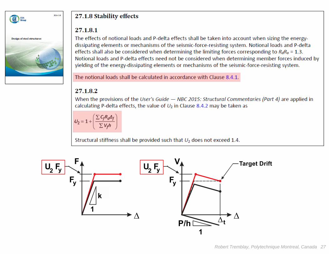
V Target Drift
F U F
y
t
2 y
P/h
U F 2 y
Robert Tremblay, Polytechnique Montreal, Canada 27
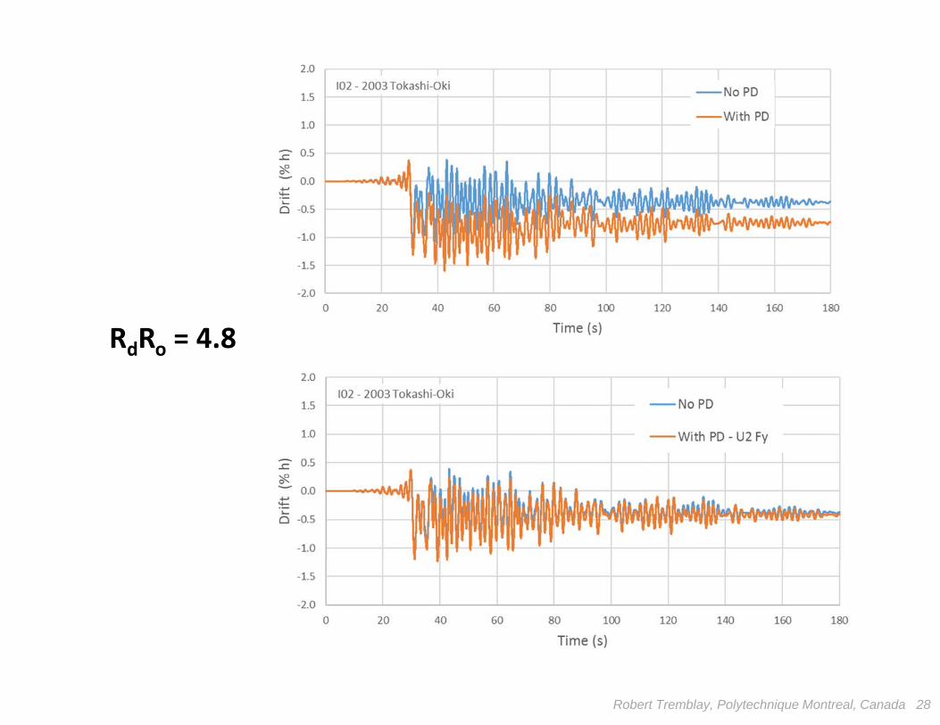
RdRo = 4.8
Robert Tremblay, Polytechnique Montreal, Canada 28
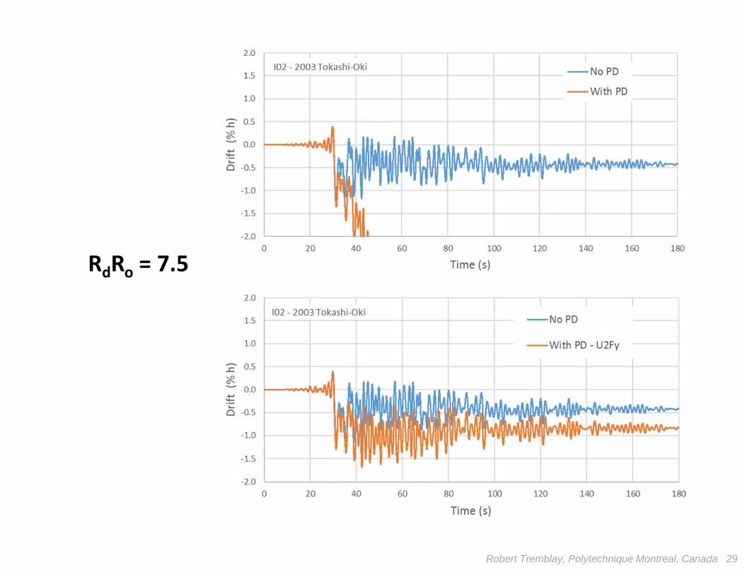
RdRo = 7.5
Robert Tremblay, Polytechnique Montreal, Canada 29

Robert Tremblay, Polytechnique Montreal, Canada 30

BRBF or FBF : RdRo = 4.8Firm Ground, Vancouver, BC
5 @ 9.0 = 45.0 m
Frame Studied
Frame ElevationPlan View
4.5 m
5 @
9.0
= 4
5.0
m
15 @
4.0
= 6
0 m
N
Gravity loads: Roof: Dead = 3.0 kPa Snow = 1.64 kPa Floor: Dead = 3.6 kPa Partitions = 1.0 kPa Live = 2.4 kPa Exterior walls = 1.2 kPa
0.25 m(typ.)
BRBF
FBF
Robert Tremblay, Polytechnique Montreal, Canada 31

Robert Tremblay, Polytechnique Montreal, Canada 32
Design BWith Stab. Provisions
102 tons3.52 s
Design ANo Stab.
Provisions
81 tons3.99 s
TonnageT1 (s)
0 1 2 3 4 5T (s)
0.00
0.04
0.08
0.12
0.16
0.20
Design Seismic LoadNBCC 2015RdRo = 4.8
Vancouver, BC (Site C)
Design B
Design A
0 0.02 0.04 0.06V / W
0
4
8
12
16
Leve
l
Design ADesign B
1.0 1.1 1.2 1.3 1.4U2
0
4
8
12
16
0.0 0.5 1.0 1.5 2.0d (%hs)
0
4
8
12
16
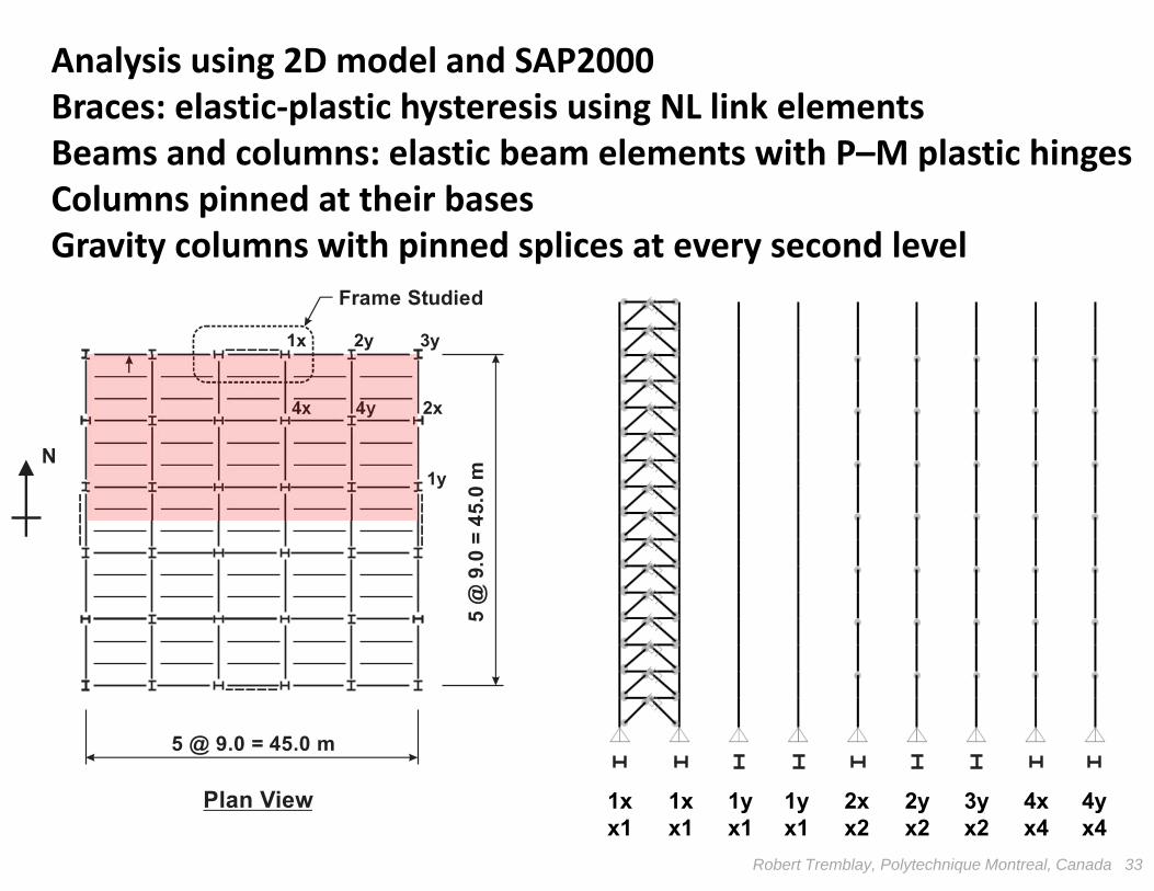
Robert Tremblay, Polytechnique Montreal, Canada 33
5 @ 9.0 = 45.0 m
Frame Studied
Plan View
5 @
9.0
= 4
5.0
m
N
1x 2y 3y
4x 4y 2x
1y
1xx1
1xx1
2xx2
1yx1
4xx4
3yx2
2yx2
1yx1
4yx4
Analysis using 2D model and SAP2000Braces: elastic‐plastic hysteresis using NL link elementsBeams and columns: elastic beam elements with P–M plastic hingesColumns pinned at their basesGravity columns with pinned splices at every second level
Robert Tremblay, Polytechnique Montreal, Canada 34
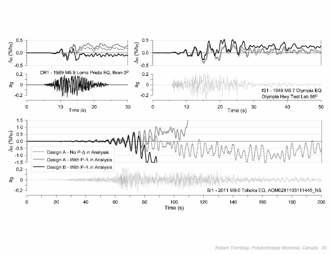
a g a g
a gn
(%h n
)
n (%
h n)
n (%
h n)
Robert Tremblay, Polytechnique Montreal, Canada 35
Robert Tremblay, Polytechnique Montreal, Canada 36
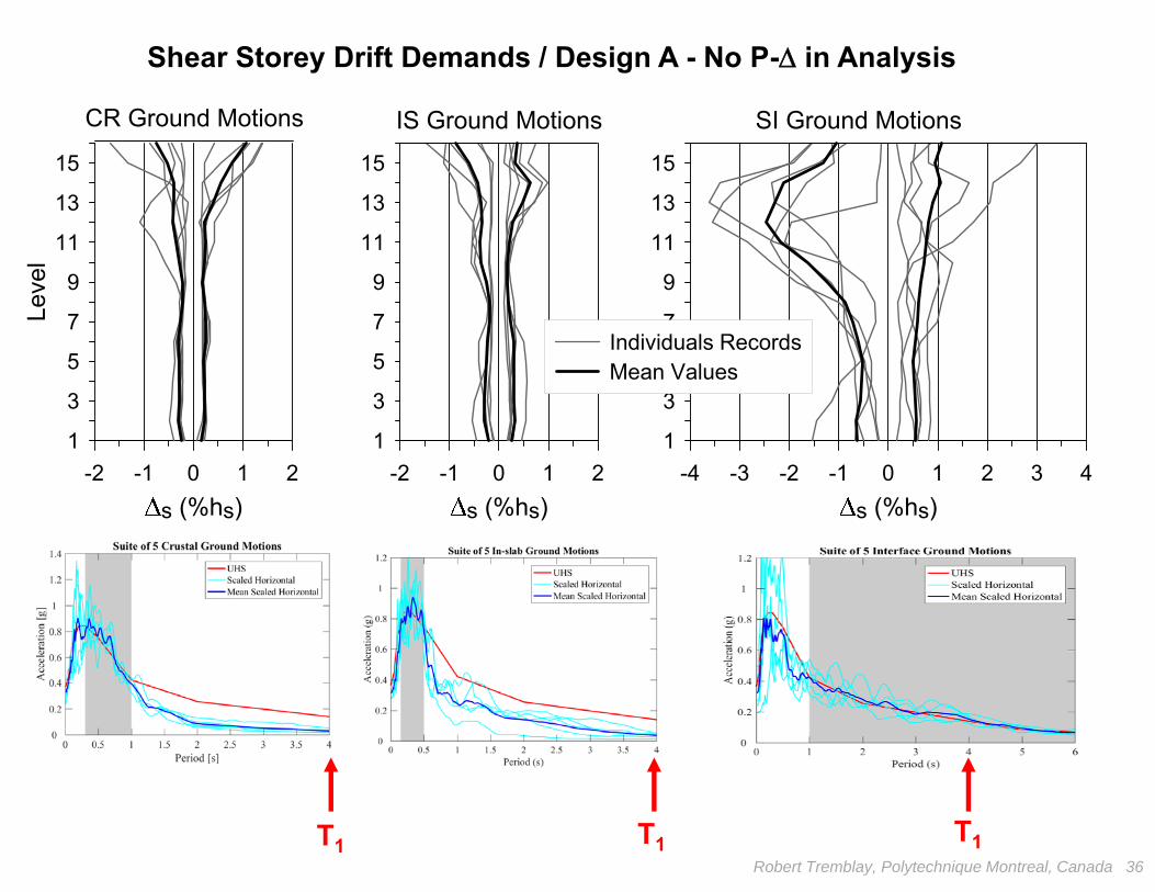
-2 -1 0 1 2s (%hs)
1
3
5
7
9
11
13
15
Leve
l
-2 -1 0 1 2s (%hs)
1
3
5
7
9
11
13
15
-4 -3 -2 -1 0 1 2 3 4s (%hs)
1
3
5
7
9
11
13
15
Individuals RecordsMean Values
CR Ground Motions IS Ground Motions SI Ground Motions
T1 T1T1
Shear Storey Drift Demands / Design A - No P- in Analysis
Robert Tremblay, Polytechnique Montreal, Canada 37
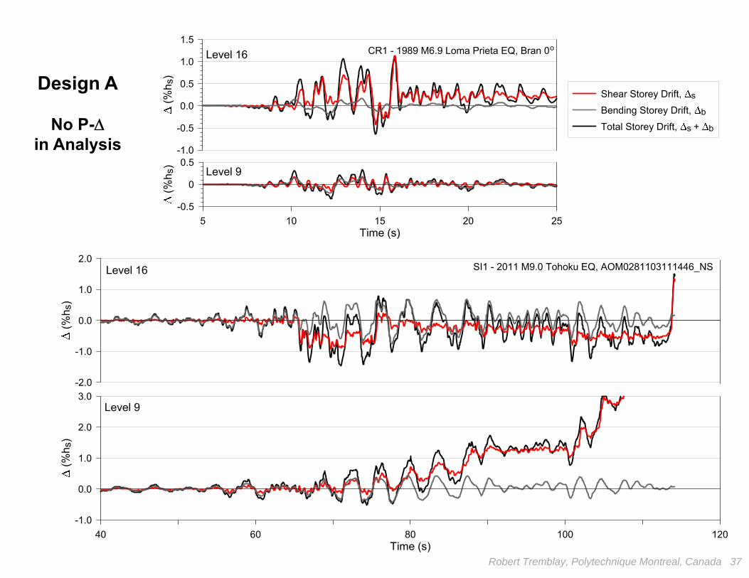
5 10 15 20 25Time (s)
-0.5
0
0.5 (%
h s)
-1.0
-0.5
0.0
0.5
1.0
1.5
(%h s
)
Shear Storey Drift, s
Bending Storey Drift, b
Total Storey Drift, s + b
SI1 - 2011 M9.0 Tohoku EQ, AOM0281103111446_NS
CR1 - 1989 M6.9 Loma Prieta EQ, Bran 0oLevel 16
Level 9
40 60 80 100 120Time (s)
-1.0
0.0
1.0
2.0
3.0
(%h s
)
Level 9
-2.0
-1.0
0.0
1.0
2.0
(%h s
)
Level 16
Design A
No P-in Analysis
Robert Tremblay, Polytechnique Montreal, Canada 38
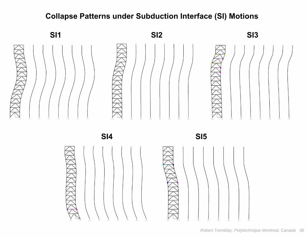
SI1 SI2 SI3
SI4 SI5
Collapse Patterns under Subduction Interface (SI) Motions
Robert Tremblay, Polytechnique Montreal, Canada 39
-1.0 0.0 1.0 2.0 3.0 4.0Storey Shear Drift, s (%hs)
-4000
-3000
-2000
-1000
0
1000
2000
3000
4000
Stor
ey S
hear
(kN
)
Design A
-4.0 -3.0 -2.0 -1.0 0.0 1.0Storey Shear Drift, s (%hs)
-4000
-3000
-2000
-1000
0
1000
2000
3000
4000
Stor
ey S
hear
(kN
)
Storeys Shears fromBraces OnlyBraces + Columns
Design B
Storey shear-Shear storey drift response at level 9 - SI1 motion:
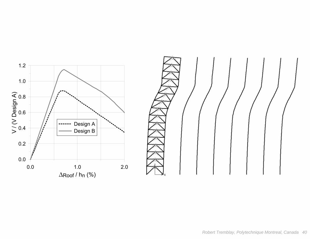
0.0 1.0 2.0Roof / hn (%)
0.0
0.2
0.4
0.6
0.8
1.0
1.2
V / (
V D
esig
n A)
Design ADesign B
Robert Tremblay, Polytechnique Montreal, Canada 40
Robert Tremblay, Polytechnique Montreal, Canada 41
k, Fy
F
F yk
1
1
V
LossFy
V
P
P/h
P
h
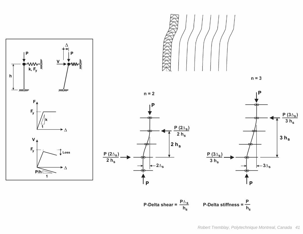
P (3 )
P (3 )
3 h
3 h
3
s
s
s
s
s
n = 3
ss
3 h 2 h
P
P (2 )
P (2 )
P PP-Delta shear = P-Delta stiffness =
2 h
2 h
h h
2
n = 2
s
s
s
s
s
s s
s
P
P P

F
-F
V+
+-V > V
y
y
VF
-F
V > V+ -
+-V V<
y
y
V V
P
k
k’
h
+ =
11
k’
k’ > P/hP/h
Robert Tremblay, Polytechnique Montreal, Canada 42
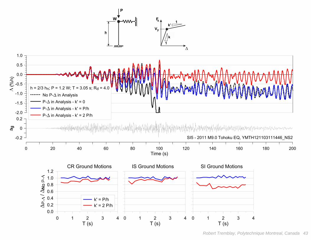
Known solution: provide k’ > P/h
Robert Tremblay, Polytechnique Montreal, Canada 43
0 1 2 3 4T (s)
0.00.20.40.60.81.01.2
k' = P/hk' = 2 P/h
0 1 2 3 4T (s)
0 1 2 3 4T (s)
CR Ground Motions IS Ground Motions SI Ground Motions
0 20 40 60 80 100 120 140 160 180 200Time (s)
-0.2
0
0.2-2.0
-1.5
-1.0
-0.5
0.0
0.5
1.0
h = 2/3 hn; P = 1.2 W; T = 3.05 s; Rd = 4.0No P- in AnalysisP- in Analysis - k' = 0P- in Analysis - k' = P/hP- in Analysis - k' = 2 P/h
SI5 - 2011 M9.0 Tohoku EQ, YMTH121103111446_NS2
FW s
Vy
k
k’
1
1
P
h
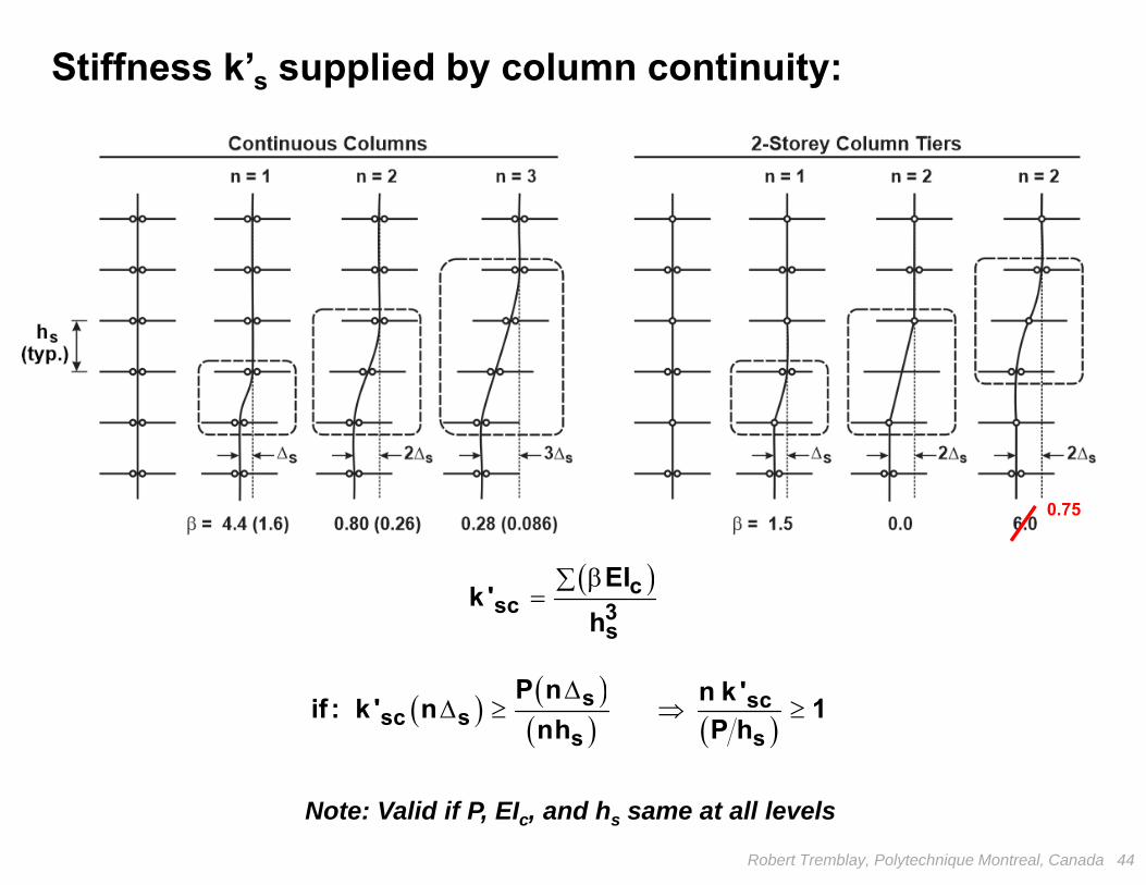
s scsc s
s s
P n n k 'if : k ' n 1nh P h
Robert Tremblay, Polytechnique Montreal, Canada 44
0.75
csc 3
s
EIk '
h
Note: Valid if P, EIc, and hs same at all levels
Stiffness k’s supplied by column continuity:
Robert Tremblay, Polytechnique Montreal, Canada 45
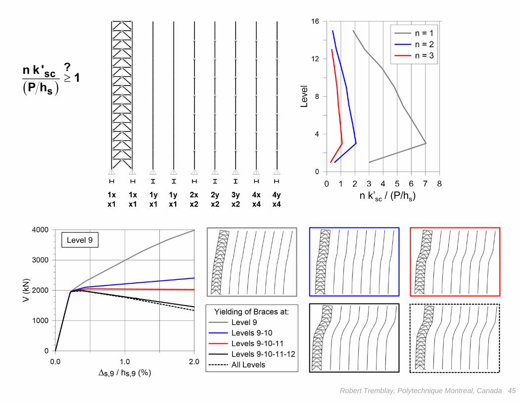
n k’sc / (P/hs)
Level 9
scs
n k ' 1P h
?
Robert Tremblay, Polytechnique Montreal, Canada 46
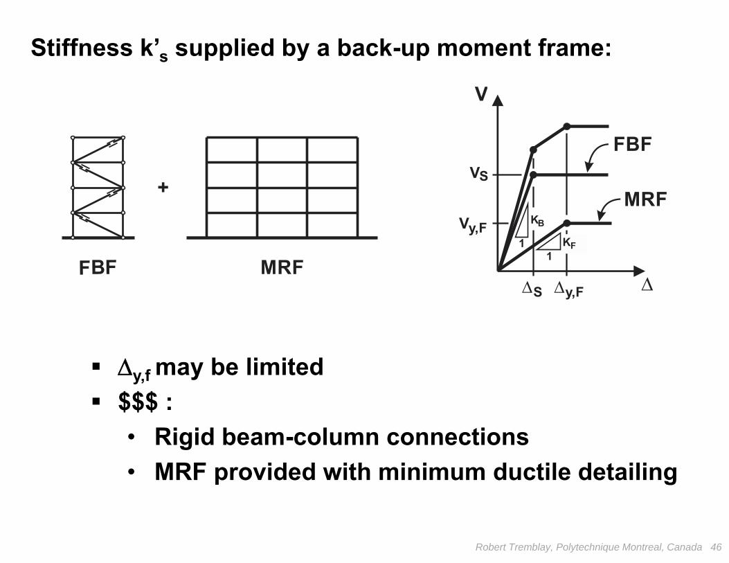
Stiffness k’s supplied by a back-up moment frame:
FBF
MRF
V
V
V
S y,F
+
FBF MRF
S
11 K
K
F
By,F
y,f may be limited $$$ :
• Rigid beam-column connections• MRF provided with minimum ductile detailing
Robert Tremblay, Polytechnique Montreal, Canada 47
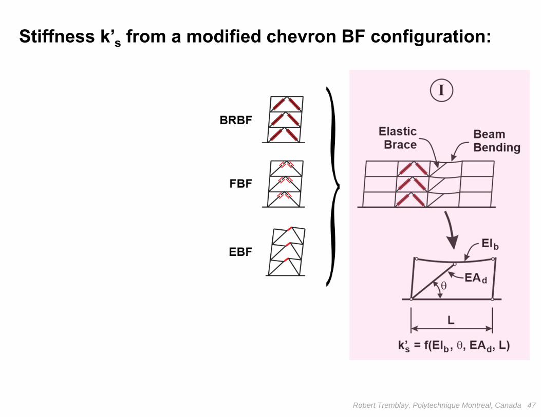
Stiffness k’s from a modified chevron BF configuration:
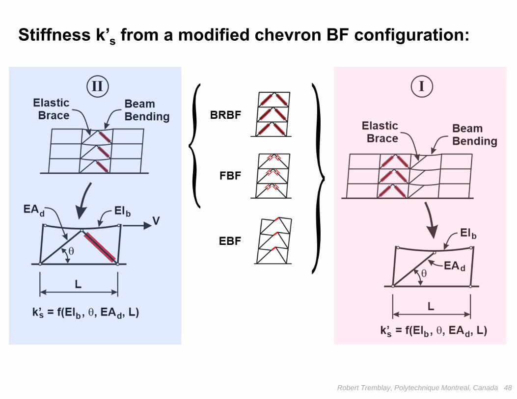
Robert Tremblay, Polytechnique Montreal, Canada 48
Stiffness k’s from a modified chevron BF configuration:
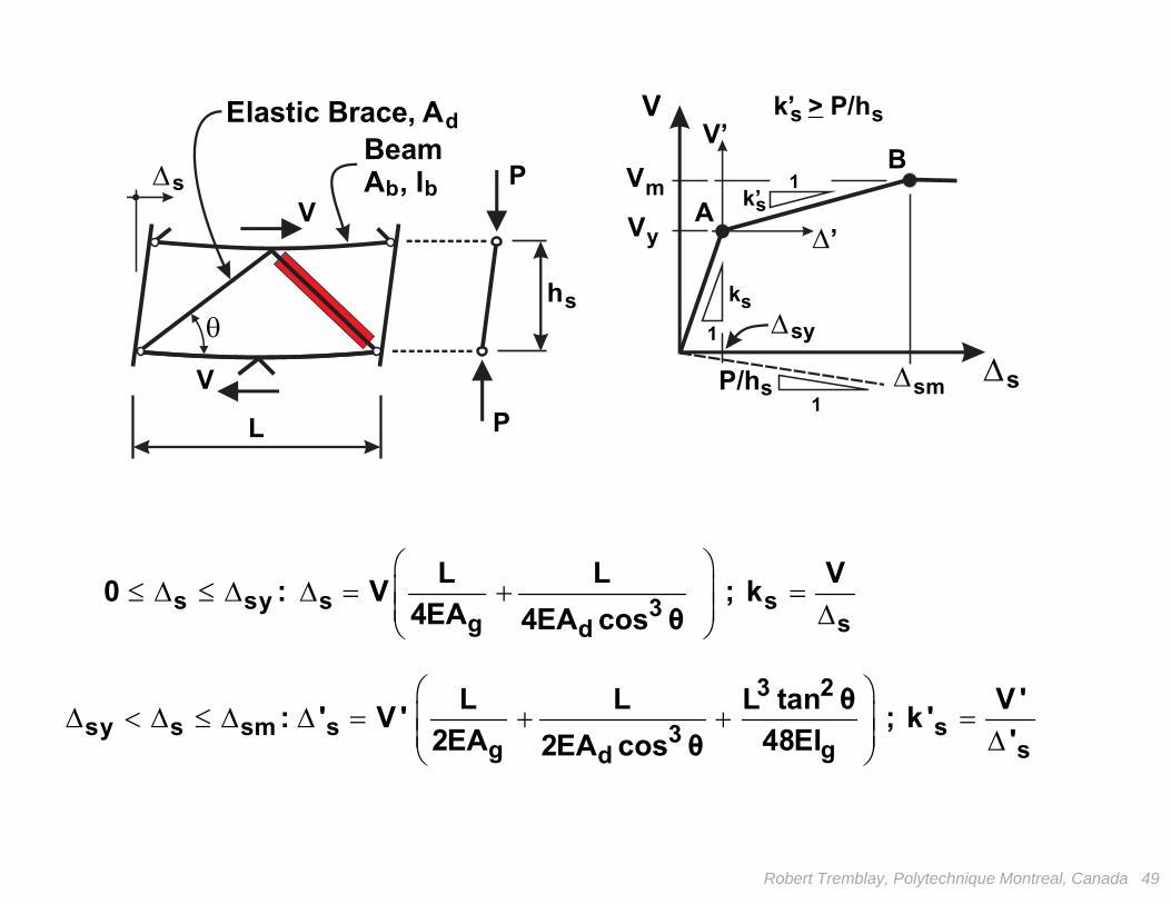
VV’
V
V
y
m
k
s
s
k’
1
1
1
B
A
s
sm s
sy
’
L
s
P/hs
sk’ P/h>
P
h
P
BeamA , I
Elastic Brace, Ad
bbs
V
V
s sy s s3g sd
L L V0 : V ; k4EA 4EA cos θ
3 2sy s sm s s3g g sd
L L L tan θ V ': ' V ' ; k '2EA 48EI '2EA cos θ
Robert Tremblay, Polytechnique Montreal, Canada 49
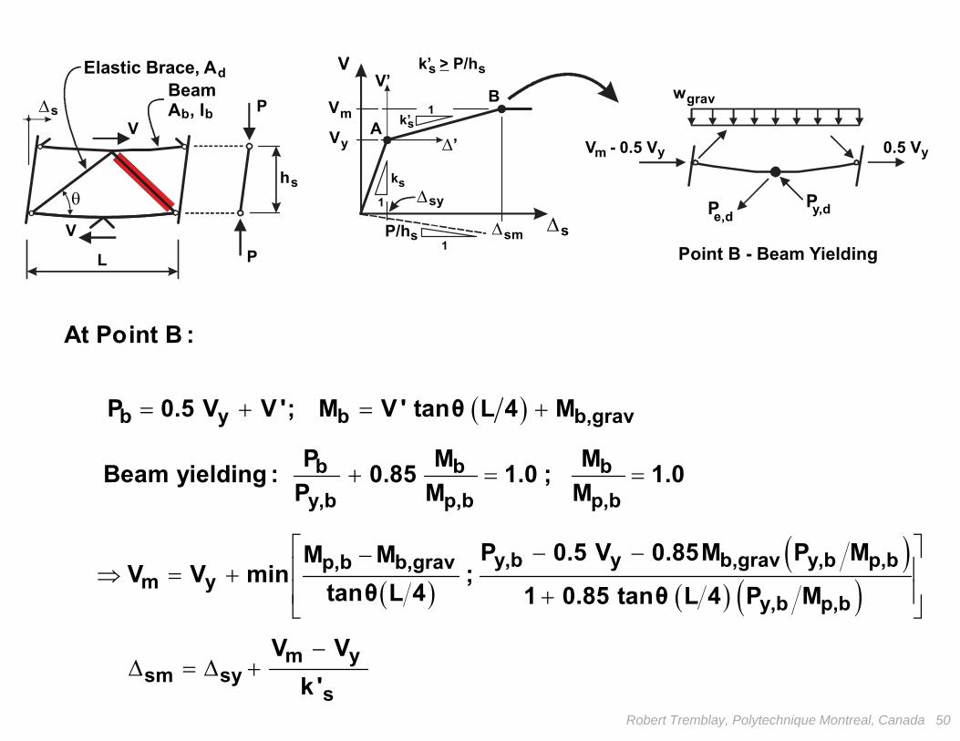
m ysm sy
s
V Vk '
Point B - Beam Yielding
VV’
V
V
y
m
k
s
s
k’
1
1
1
B
A
s
sm s
sy
’
PP
V - 0.5 V
wgrav
0.5 V ym y
y,de,d
L
s
P/hs
sk’ P/h>
P
h
P
BeamA , I
Elastic Brace, Ad
bbs
V
V
b y b b,grav
At Point B :
P 0.5 V V '; M V ' tanθ L 4 M
y,b y b,grav y,b p,bp,b b,grav
m yy,b p,b
P 0.5 V 0.85M P MM MV V min ;
tanθ L 4 1 0.85 tanθ L 4 P M
b b by,b p,b p,b
P M MBeam yielding : 0.85 1.0 ; 1.0P M M
Robert Tremblay, Polytechnique Montreal, Canada 50

Point B - Beam Yielding
VV’
V
V
y
m
k
s
s
k’
1
1
1
B
A
s
sm s
sy
’
PP
V - 0.5 V
wgrav
0.5 V ym y
y,de,d
L
s
P/hs
sk’ P/h>
P
h
P
BeamA , I
Elastic Brace, Ad
bbs
V
V
m ye,d
m yc
At Point B :
V V 2P
cosθ
V VP
2 tanθ
Robert Tremblay, Polytechnique Montreal, Canada 51
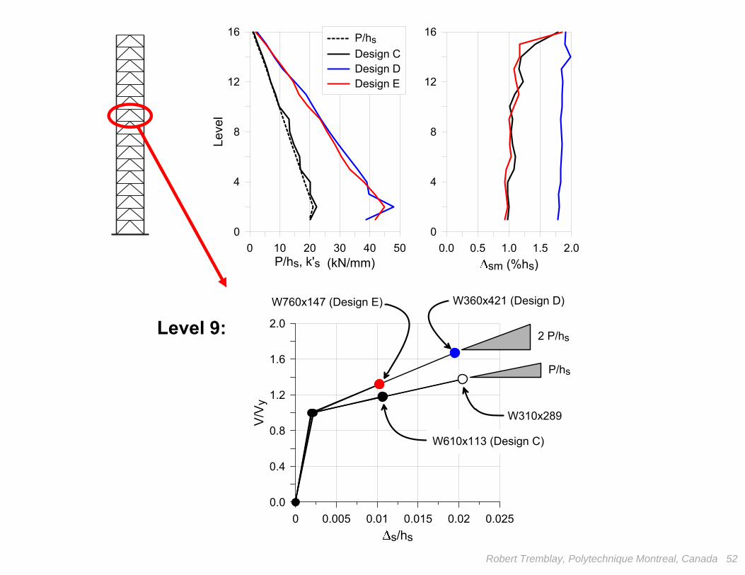
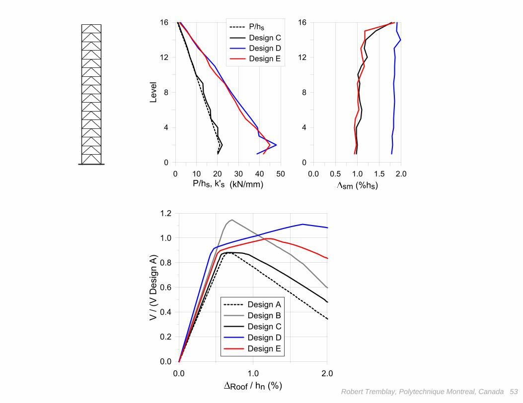
0 10 20 30 40 50P/hs, k's (kN/mm)
0
4
8
12
16
Leve
l
P/hsDesign CDesign DDesign E
0.0 0.5 1.0 1.5 2.0sm (%hs)
0
4
8
12
16
Robert Tremblay, Polytechnique Montreal, Canada 52
0 0.005 0.01 0.015 0.02 0.025s/hs
0.0
0.4
0.8
1.2
1.6
2.0
V/V y
W760x147 (Design E) W360x421 (Design D)
W310x289
W610x113 (Design C)
P/hs
2 P/hsLevel 9:
Robert Tremblay, Polytechnique Montreal, Canada 53
0.0 1.0 2.0Roof / hn (%)
0.0
0.2
0.4
0.6
0.8
1.0
1.2
V / (
V D
esig
n A)
Design ADesign BDesign CDesign DDesign E
0 10 20 30 40 50P/hs, k's (kN/mm)
0
4
8
12
16
Leve
l
P/hsDesign CDesign DDesign E
0.0 0.5 1.0 1.5 2.0sm (%hs)
0
4
8
12
16
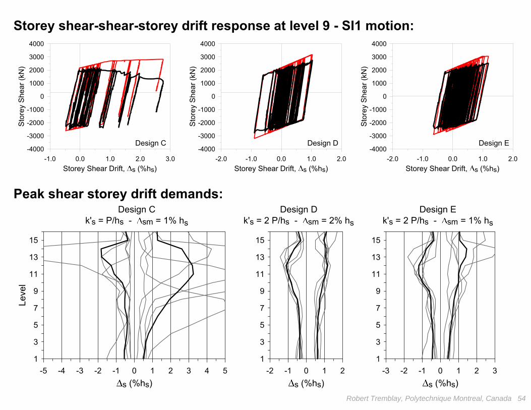
-1.0 0.0 1.0 2.0 3.0Storey Shear Drift, s (%hs)
-4000
-3000
-2000
-1000
0
1000
2000
3000
4000
Stor
ey S
hear
(kN
)
Design C
-2.0 -1.0 0.0 1.0 2.0Storey Shear Drift, s (%hs)
-4000
-3000
-2000
-1000
0
1000
2000
3000
4000
Stor
ey S
hear
(kN
)
Design D
-2.0 -1.0 0.0 1.0 2.0Storey Shear Drift, s (%hs)
-4000
-3000
-2000
-1000
0
1000
2000
3000
4000
Stor
ey S
hear
(kN
)
Design E
Robert Tremblay, Polytechnique Montreal, Canada 54
1
3
5
7
9
11
13
15
-3 -2 -1 0 1 2 3s (%hs)
-5 -4 -3 -2 -1 0 1 2 3 4 5s (%hs)
1
3
5
7
9
11
13
15
Leve
l
Design Ck's = P/hs - sm = 1% hs
-2 -1 0 1 2s (%hs)
1
3
5
7
9
11
13
15
Design Ek's = 2 P/hs - sm = 1% hs
Design Dk's = 2 P/hs - sm = 2% hs
Storey shear-shear-storey drift response at level 9 - SI1 motion:
Peak shear storey drift demands:
Robert Tremblay, Polytechnique Montreal, Canada 55
Design
V/W (%)T1 (s)
Tonnage (t)
A
4.443.9981
B
5.463.52102
C
4.443.8587
D
4.443.35153
E
4.443.5199
a gn
(%h n
)
Robert Tremblay, Polytechnique Montreal, Canada 56
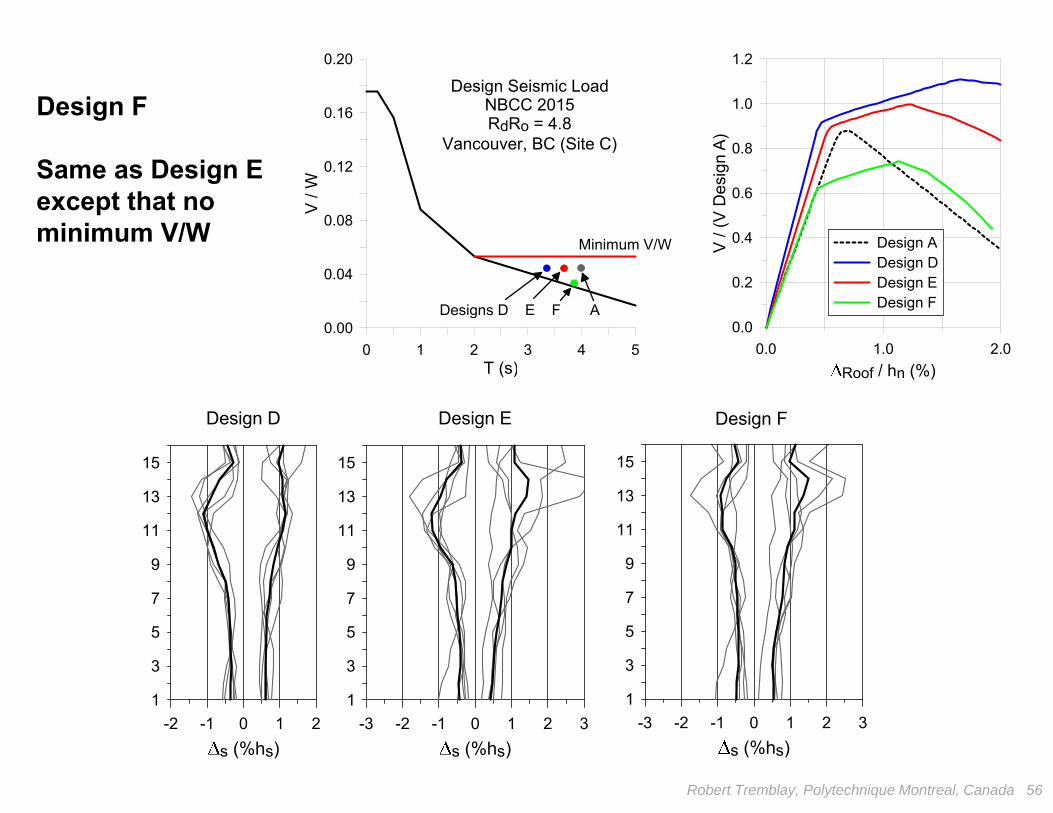
0.0 1.0 2.0Roof / hn (%)
0.0
0.2
0.4
0.6
0.8
1.0
1.2
V / (
V D
esig
n A)
Design ADesign DDesign EDesign F
1
3
5
7
9
11
13
15
-3 -2 -1 0 1 2 3
s (%hs)
Design D
-2 -1 0 1 2
s (%hs)
1
3
5
7
9
11
13
15
Design E
1
3
5
7
9
11
13
15
-3 -2 -1 0 1 2 3
s (%hs)
Design F
Design F
Same as Design Eexcept that no minimum V/W
0 1 2 3 4 5T (s)
0.00
0.04
0.08
0.12
0.16
0.20
V / W
Design Seismic LoadNBCC 2015RdRo = 4.8
Vancouver, BC (Site C)
Minimum V/W
Designs D E F A
Robert Tremblay, Polytechnique Montreal, Canada 57
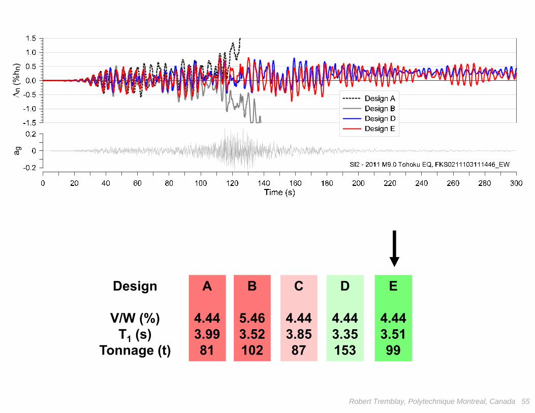
Design
V/W (%)T1 (s)
Tonnage (t)
A
4.443.9981
B
5.463.52102
C
4.443.8587
D
4.443.35153
E
4.443.5199
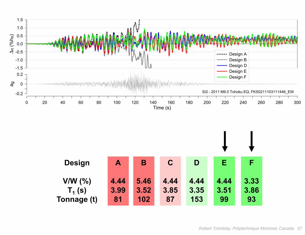
F
3.333.8693
0 20 40 60 80 100 120 140 160 180 200 220 240 260 280 300Time (s)
-0.2
0
0.2
a g
-1.5
-1.0
-0.5
0.0
0.5
1.0
1.5
n (%
h n)
Design ADesign BDesign DDesign EDesign F
SI2 - 2011 M9.0 Tohoku EQ, FKS0211103111446_EW

• Collapse of tall braced frames with limited post-yielding stiffness expected under subduction interface EQs
• Current design provisions (strength amplification, column continuity) and/or systems (limited post-yield stiffness) need to be modified
• Positive post-yielding stiffness appears as a possible solution; proposed modified chevron BF configuration appears as a promising application:
– System exhibits stable response and offers re-centring capacity with reduced peak and residual storey drifts
– Number of yielding braces reduced by 50% and limited additional steel required for the beams
– Possibility of relaxing current code limits (heigth, V/W)
Conclusions
Robert Tremblay, Polytechnique Montreal, Canada 58
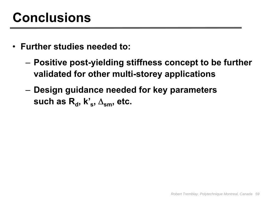
• Further studies needed to:
– Positive post-yielding stiffness concept to be further validated for other multi-storey applications
– Design guidance needed for key parameterssuch as Rd, k’s, sm, etc.
Conclusions
Robert Tremblay, Polytechnique Montreal, Canada 59


![Comparison of Seismic Design Provisions in Canada, … · Comparison of Seismic Design Provisions in ... National Building Code of Canada (NBCC) [1] whereas the latest design and](https://img.pdfslide.us/doc/110x75/5ae36e957f8b9a7b218d0fbb/comparison-of-seismic-design-provisions-in-canada-of-seismic-design-provisions.jpg)