Embed Size (px)
Citation preview
An Introduction to Workflow Modeling using Activity Models
Robert B. FranceColorado State University
Software Development Phases• System Engineering (Business Process Engineering)
– Focus on understanding the context in which software will operate
• Software Requirements Analysis– Focus on understanding specific parts of system problem targeted
by software
• Design– Focus on developing a solution that satisfies the requirements– Two sub-phases: Architectural design; Detailed design
• Implementation– Focus on developing an executable and deployable form of the
design
© Robert B. France Intro-2
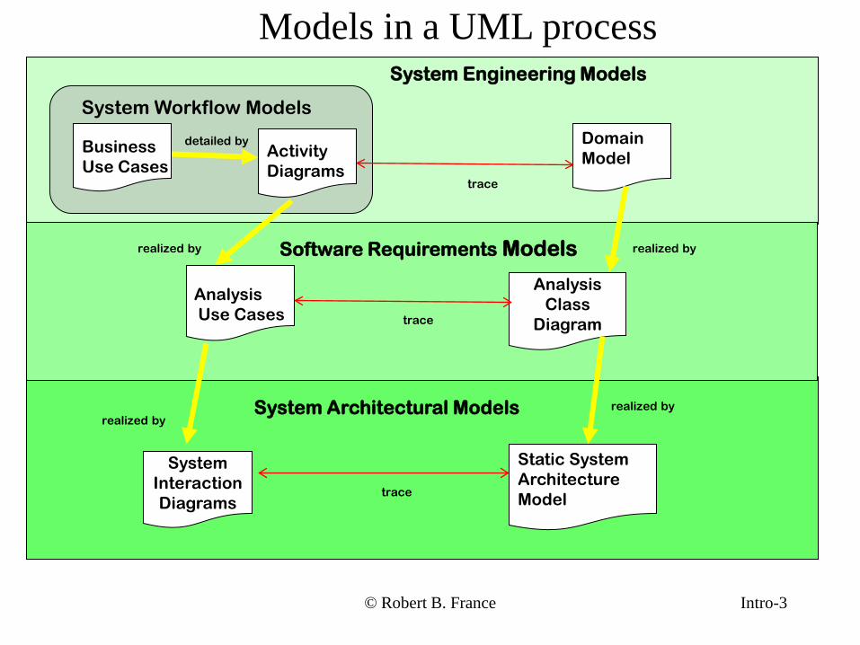
Models in a UML processSystem Engineering Models
Domain ModelActivity
Diagrams
Business Use Cases
System Workflow Models
System Architectural Models
Software Requirements Models
AnalysisUse Cases
AnalysisClass
Diagram
SystemInteractionDiagrams
Static System ArchitectureModel
realized by
detailed by
realized by
realized by
trace
trace
Intro-3© Robert B. France
realized by
trace
© Robert B. France Intro-4
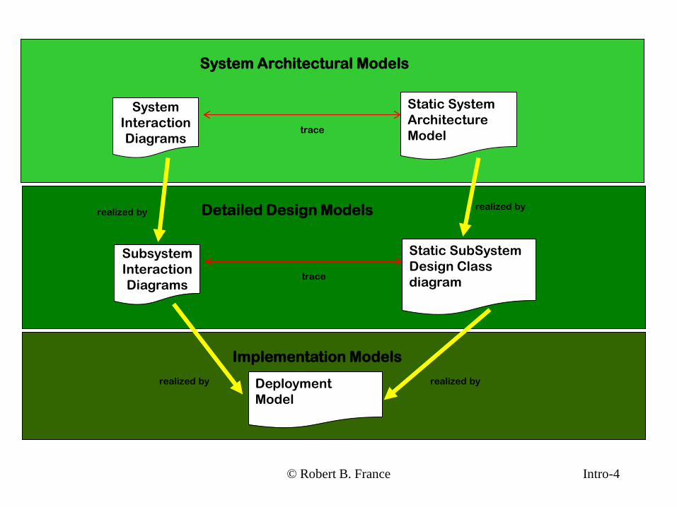
System Architectural Models
SystemInteractionDiagrams
Static System ArchitectureModeltrace
Detailed Design Models
SubsystemInteractionDiagrams
Static SubSystemDesign Classdiagram
realized byrealized by
trace
Implementation Models
DeploymentModel
realized byrealized by
5
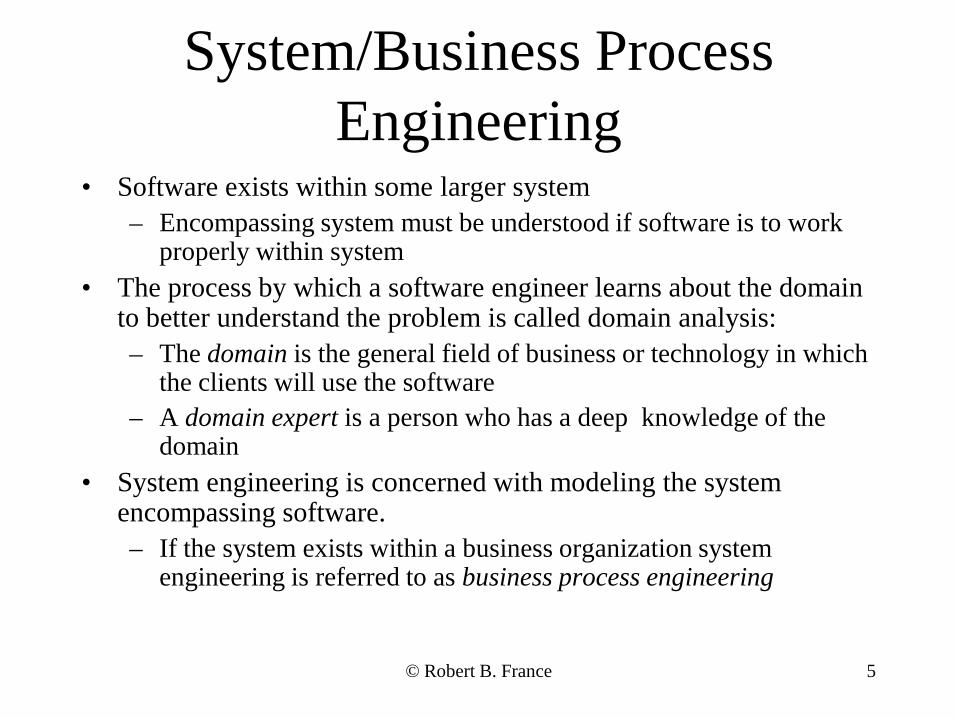
System/Business Process Engineering
• Software exists within some larger system– Encompassing system must be understood if software is to work
properly within system• The process by which a software engineer learns about the domain
to better understand the problem is called domain analysis:– The domain is the general field of business or technology in which
the clients will use the software– A domain expert is a person who has a deep knowledge of the
domain• System engineering is concerned with modeling the system
encompassing software.– If the system exists within a business organization system
engineering is referred to as business process engineering
© Robert B. France
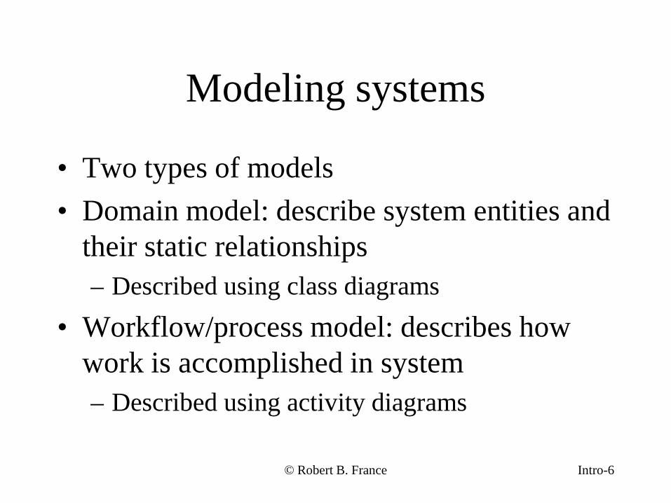
Modeling systems
• Two types of models• Domain model: describe system entities and
their static relationships– Described using class diagrams
• Workflow/process model: describes how work is accomplished in system– Described using activity diagrams
© Robert B. France Intro-6
© Clear View Training 2010 v2.6 7
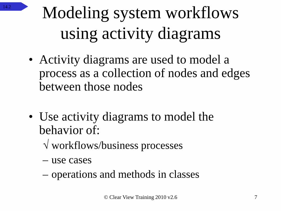
Modeling system workflows using activity diagrams
• Activity diagrams are used to model a process as a collection of nodes and edgesbetween those nodes
• Use activity diagrams to model the behavior of:√ workflows/business processes– use cases– operations and methods in classes
14.2
© Clear View Training 2010 v2.6 8
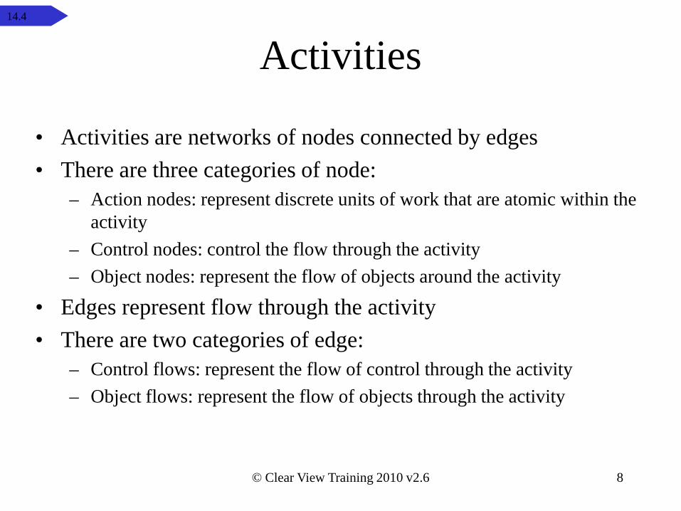
Activities
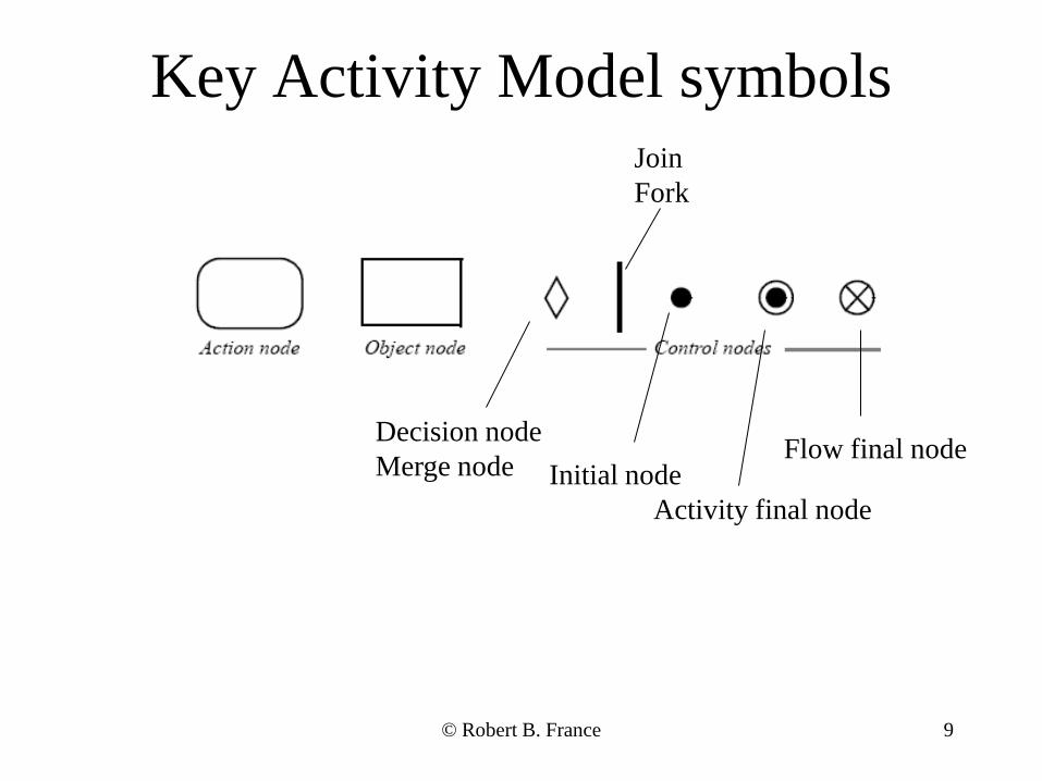
• Activities are networks of nodes connected by edges• There are three categories of node:
– Action nodes: represent discrete units of work that are atomic within the activity
– Control nodes: control the flow through the activity– Object nodes: represent the flow of objects around the activity
• Edges represent flow through the activity• There are two categories of edge:
– Control flows: represent the flow of control through the activity– Object flows: represent the flow of objects through the activity
14.4
9
Key Activity Model symbols
Initial nodeDecision nodeMerge node
Activity final node
Flow final node
JoinFork
© Robert B. France
10
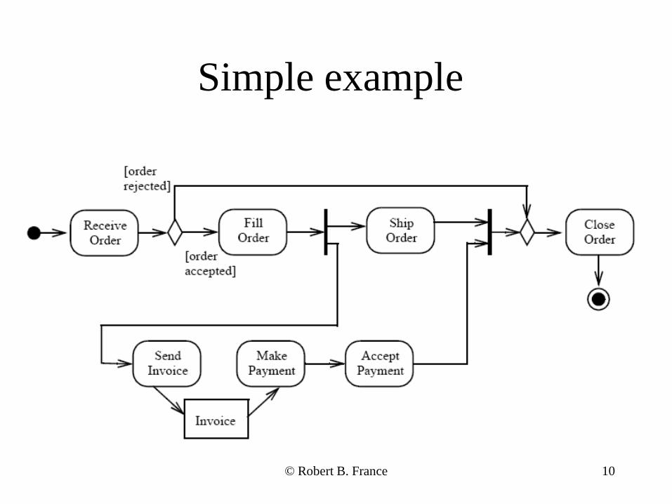
Simple example
© Robert B. France
© Clear View Training 2010 v2.6 11
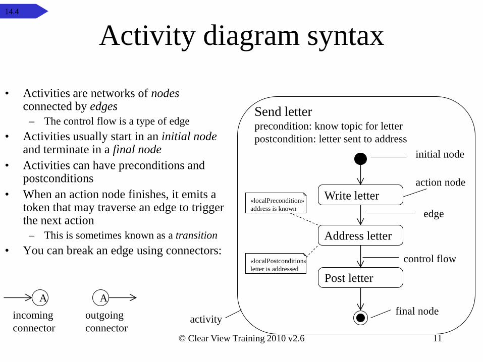
Activity diagram syntax
• Activities are networks of nodesconnected by edges
– The control flow is a type of edge• Activities usually start in an initial node
and terminate in a final node• Activities can have preconditions and
postconditions• When an action node finishes, it emits a
token that may traverse an edge to trigger the next action
– This is sometimes known as a transition• You can break an edge using connectors:
Address letter
Post letter
Write letteraction node
Send letter
control flow
activity
initial node
final node
precondition: know topic for letterpostcondition: letter sent to address
edge«localPrecondition»address is known
«localPostcondition»letter is addressed
AAincomingconnector
outgoingconnector
14.4
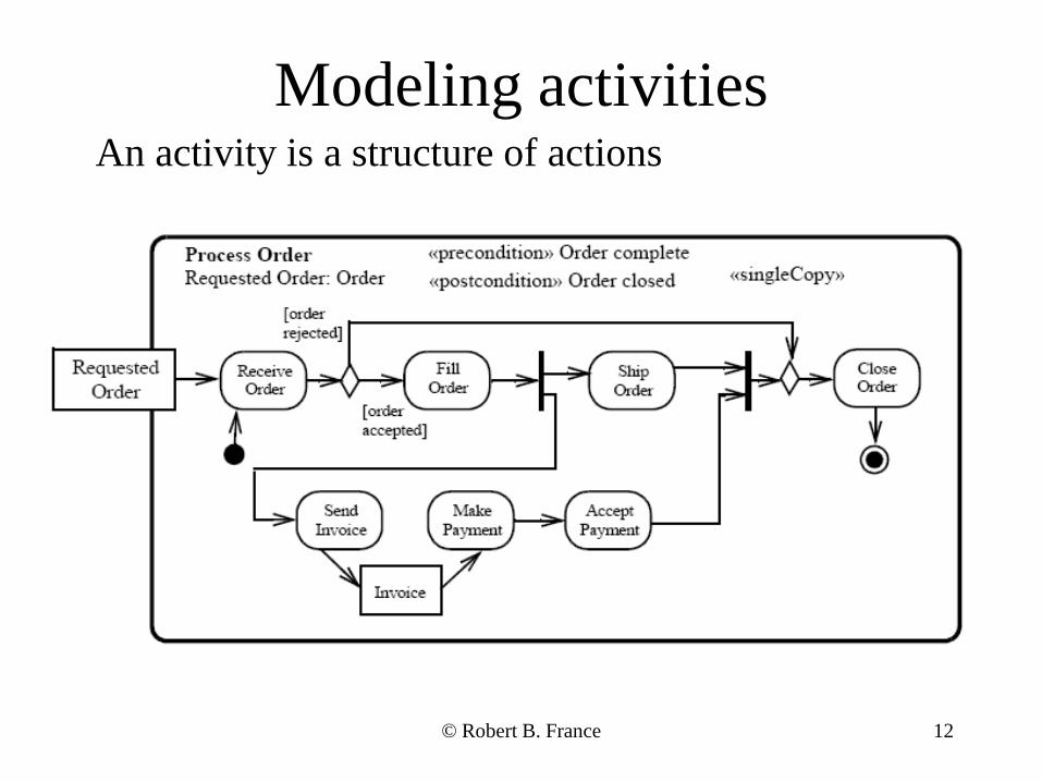
12
Modeling activitiesAn activity is a structure of actions
© Robert B. France
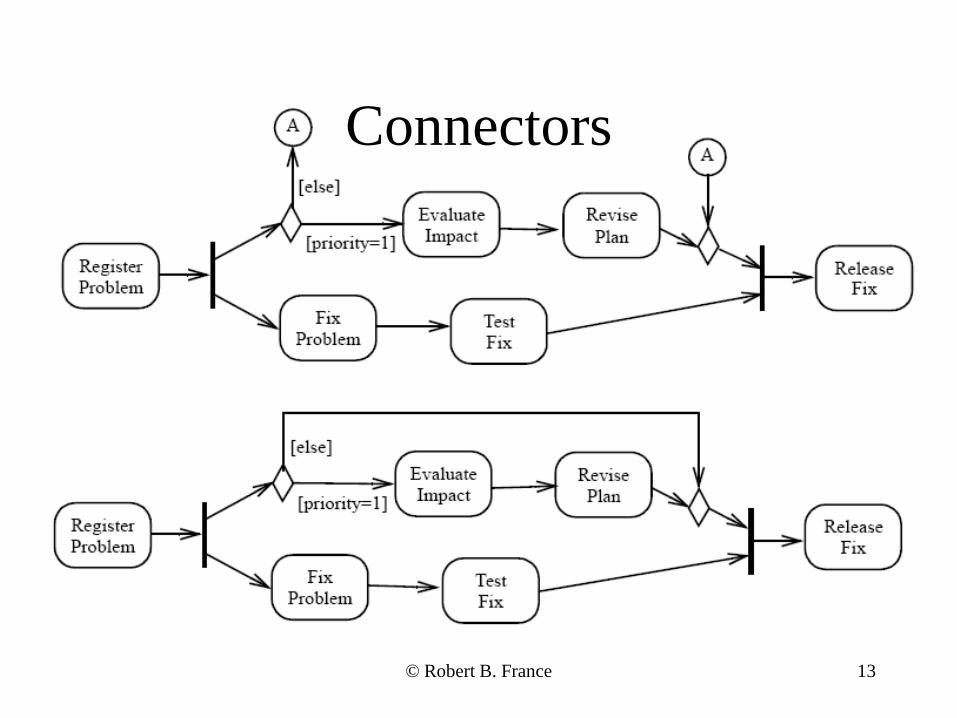
13
Connectors
© Robert B. France
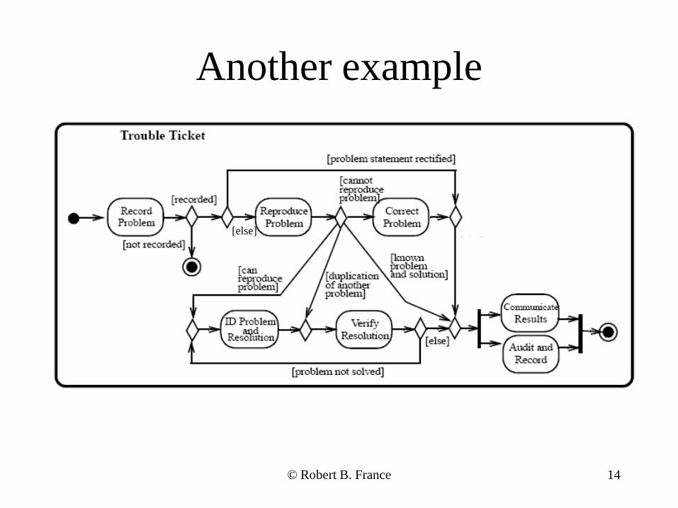
14
Another example
[else]
© Robert B. France
© Clear View Training 2010 v2.6 15
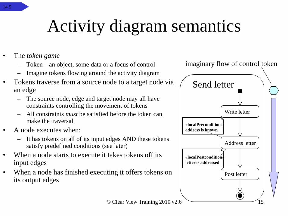
Activity diagram semantics• The token game
– Token – an object, some data or a focus of control– Imagine tokens flowing around the activity diagram
• Tokens traverse from a source node to a target node via an edge
– The source node, edge and target node may all have constraints controlling the movement of tokens
– All constraints must be satisfied before the token can make the traversal
• A node executes when:– It has tokens on all of its input edges AND these tokens
satisfy predefined conditions (see later)• When a node starts to execute it takes tokens off its
input edges• When a node has finished executing it offers tokens on
its output edges
Address letter
Post letter
Write letter
Send letter
imaginary flow of control token
«localPrecondition»address is known
«localPostcondition»letter is addressed
14.5
© Clear View Training 2010 v2.6 16
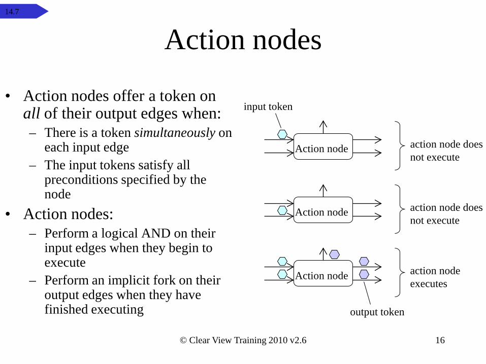
Action nodes
• Action nodes offer a token on all of their output edges when:– There is a token simultaneously on
each input edge– The input tokens satisfy all
preconditions specified by the node
• Action nodes:– Perform a logical AND on their
input edges when they begin to execute
– Perform an implicit fork on their output edges when they have finished executing
Action node
Action node
Action node
input token
output token
action node doesnot execute
action node doesnot execute
action nodeexecutes
14.7
© Clear View Training 2010 v2.6 17
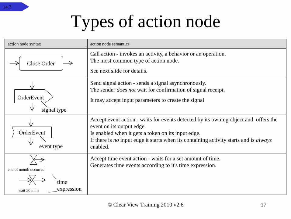
Types of action node
end of month occurred
time expression
event type
OrderEvent
wait 30 mins
Accept event action - waits for events detected by its owning object and offers the event on its output edge.Is enabled when it gets a token on its input edge.If there is no input edge it starts when its containing activity starts and is alwaysenabled.
Accept time event action - waits for a set amount of time.Generates time events according to it's time expression.
action node syntax action node semantics
Close Order
Call action - invokes an activity, a behavior or an operation.The most common type of action node.
See next slide for details.
signal type
OrderEvent
Send signal action - sends a signal asynchronously.The sender does not wait for confirmation of signal receipt.
It may accept input parameters to create the signal
14.7
© Clear View Training 2010 v2.6 18
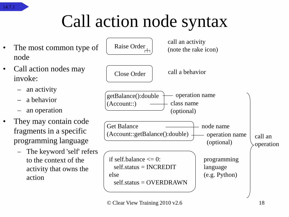
Call action node syntaxRaise Order
call an activity (note the rake icon)
Close Order call a behavior
call an operation
getBalance():double(Account::)
operation nameclass name(optional)
Get Balance(Account::getBalance():double)
node nameoperation name(optional)
if self.balance <= 0:self.status = INCREDIT
elseself.status = OVERDRAWN
programming language (e.g. Python)
• The most common type of node
• Call action nodes may invoke:
– an activity– a behavior– an operation
• They may contain code fragments in a specific programming language
– The keyword 'self' refers to the context of the activity that owns the action
14.7.1
© Clear View Training 2010 v2.6 19
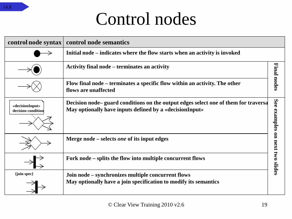
Control nodes
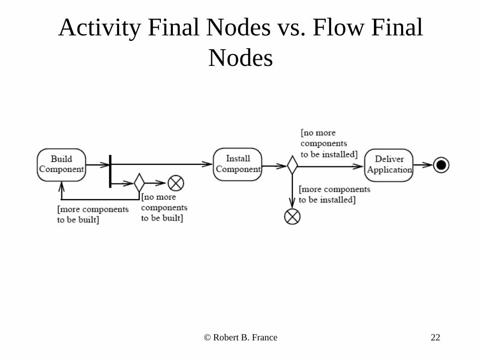
Activity final node – terminates an activity
Flow final node – terminates a specific flow within an activity. The other flows are unaffected
Initial node – indicates where the flow starts when an activity is invoked
Merge node – selects one of its input edges
Fork node – splits the flow into multiple concurrent flows
Join node – synchronizes multiple concurrent flowsMay optionally have a join specification to modify its semantics
Final nodes
«decisionInput»decision condition
Decision node– guard conditions on the output edges select one of them for traversalMay optionally have inputs defined by a «decisionInput»
{join spec}
control node syntax control node semantics
See examples on next tw
o slides14.8
© Clear View Training 2010 v2.6 20
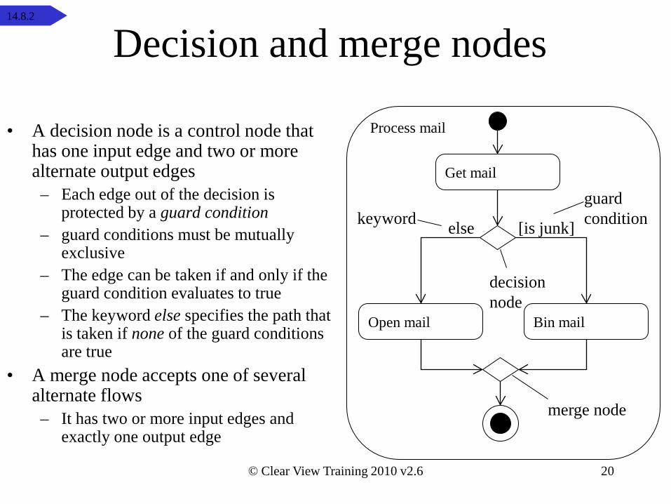
Decision and merge nodes
• A decision node is a control node thathas one input edge and two or more alternate output edges
– Each edge out of the decision is protected by a guard condition
– guard conditions must be mutually exclusive
– The edge can be taken if and only if the guard condition evaluates to true
– The keyword else specifies the path that is taken if none of the guard conditionsare true
• A merge node accepts one of several alternate flows
– It has two or more input edges and exactly one output edge
Bin mailOpen mail
Get mail
[is junk]else
Process mail
keywordguard condition
decision node
merge node
14.8.2
© Clear View Training 2010 v2.6 21
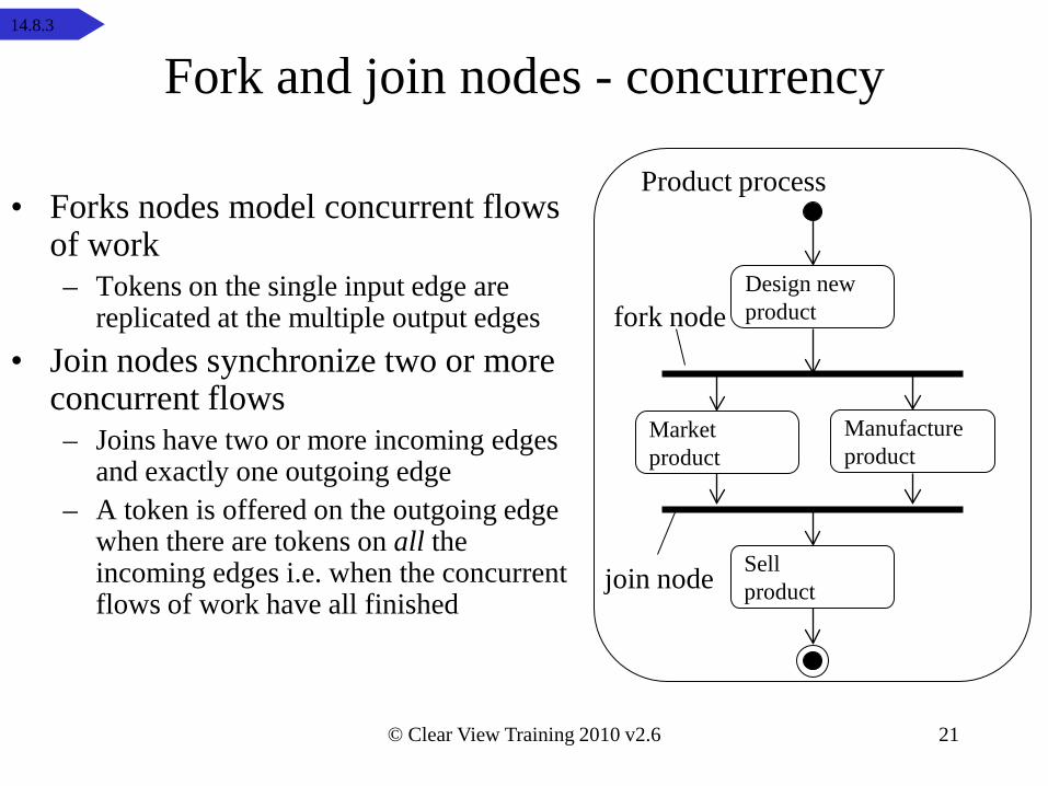
Fork and join nodes - concurrency
• Forks nodes model concurrent flows of work– Tokens on the single input edge are
replicated at the multiple output edges• Join nodes synchronize two or more
concurrent flows– Joins have two or more incoming edges
and exactly one outgoing edge– A token is offered on the outgoing edge
when there are tokens on all the incoming edges i.e. when the concurrent flows of work have all finished
Design new product
Market product
Manufactureproduct
Sell product
Product process
fork node
join node
14.8.3
22
Activity Final Nodes vs. Flow Final Nodes
© Robert B. France
© Clear View Training 2010 v2.6 23
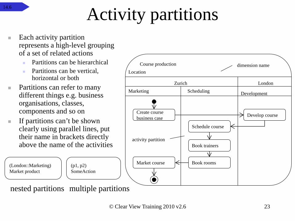
Activity partitions
Location
Marketing Development
Create course business case Develop course
Scheduling
Book trainers
Book roomsMarket course
Course production dimension name
activity partition
Schedule course
Zurich London
Each activity partitionrepresents a high-level grouping of a set of related actions Partitions can be hierarchical Partitions can be vertical,
horizontal or both Partitions can refer to many
different things e.g. business organisations, classes, components and so on
If partitions can’t be shown clearly using parallel lines, put their name in brackets directly above the name of the activities
(London::Marketing)Market product
(p1, p2)SomeAction
multiple partitionsnested partitions
14.6
24
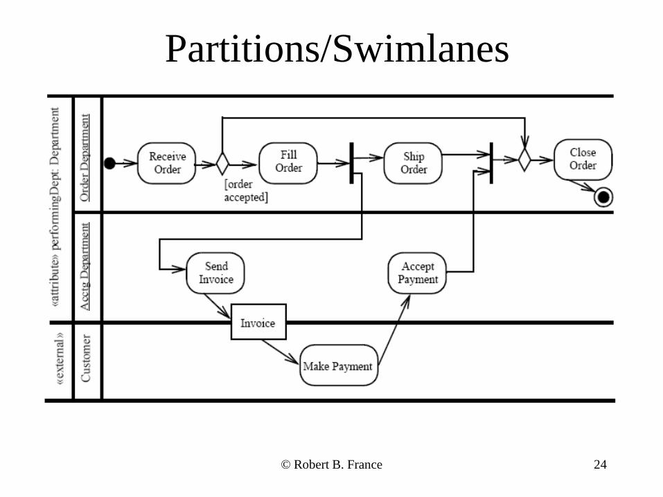
Partitions/Swimlanes
© Robert B. France
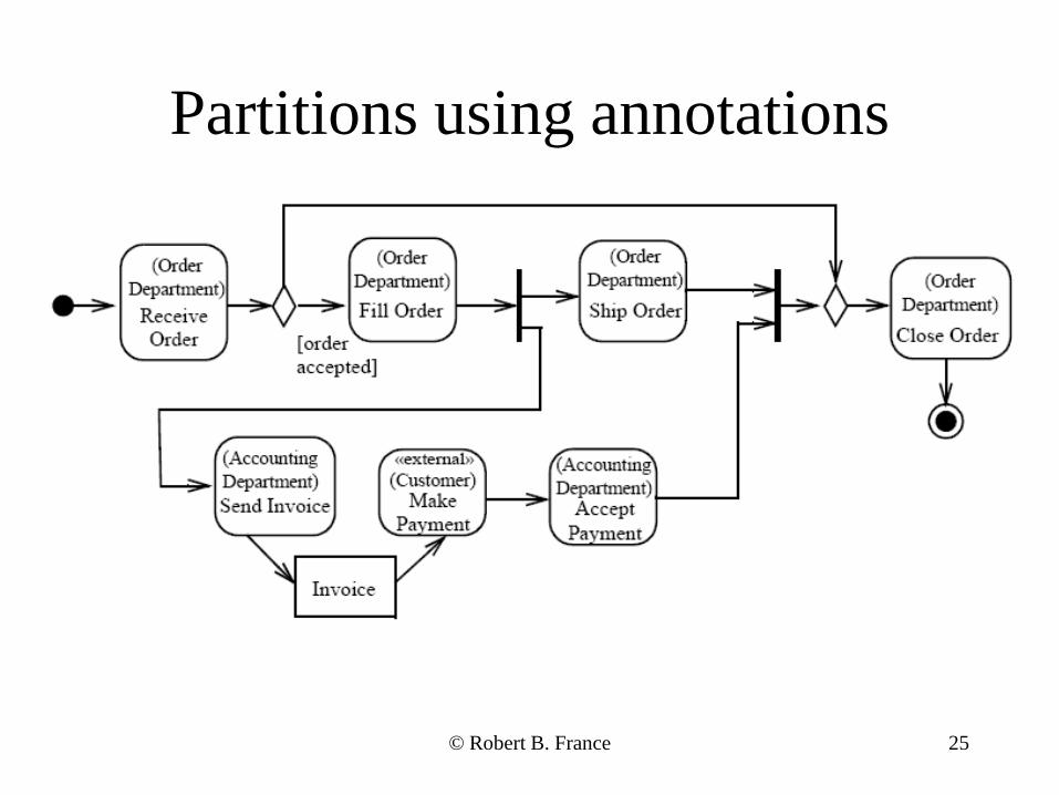
25
Partitions using annotations
© Robert B. France
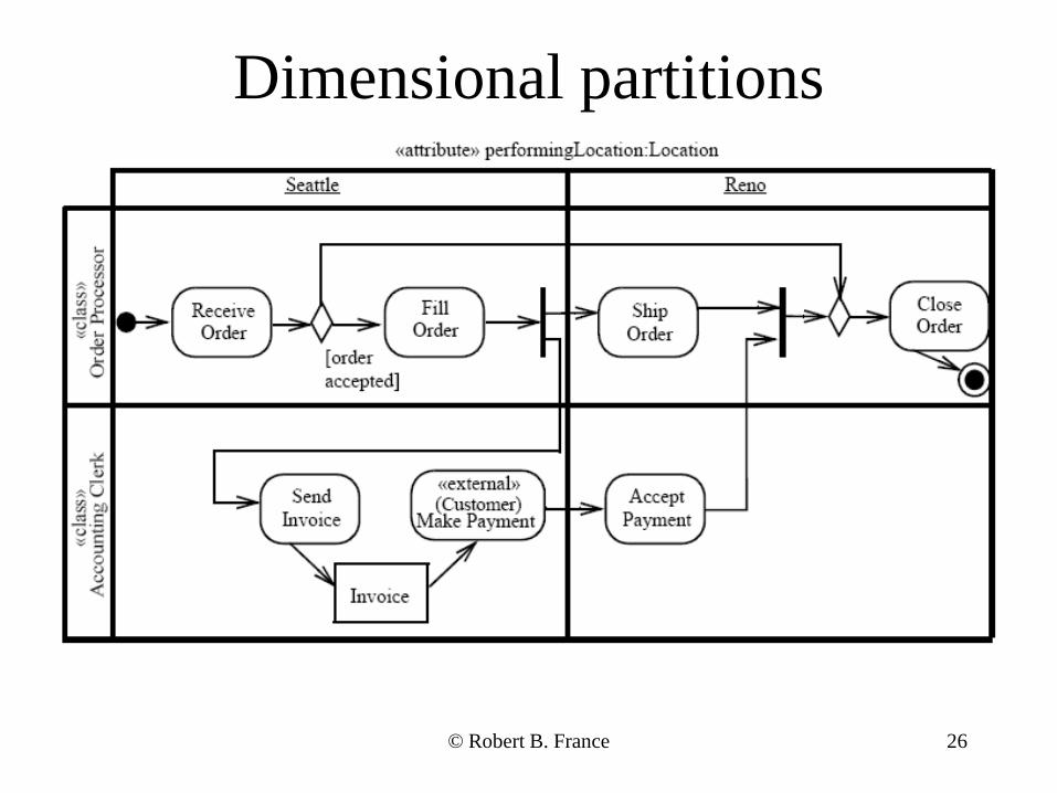
26
Dimensional partitions
© Robert B. France
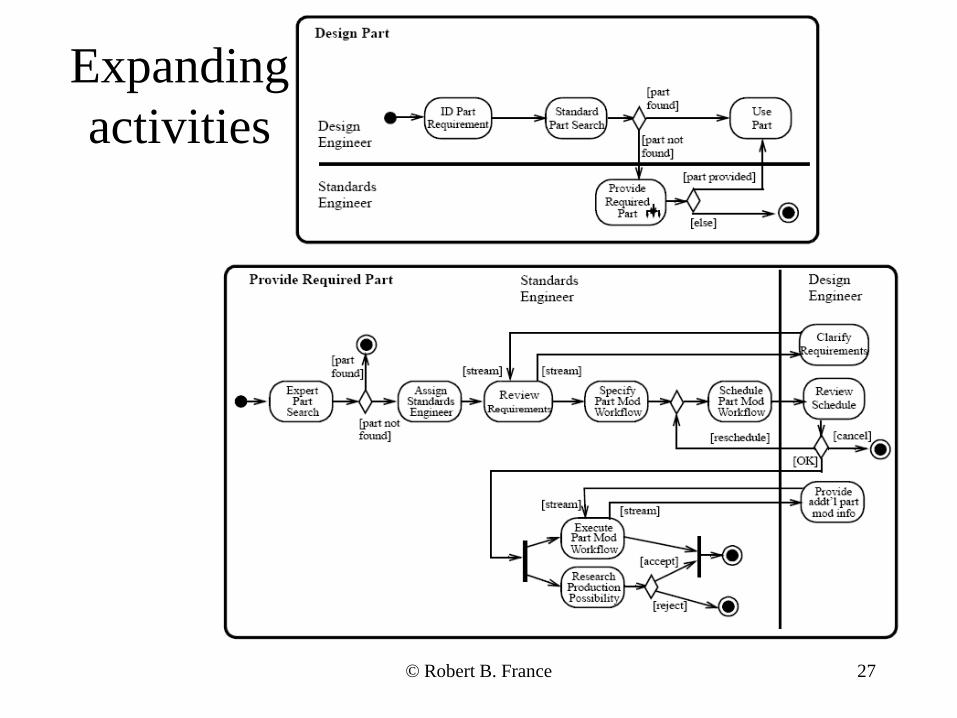
27
Expanding activities
© Robert B. France
© Clear View Training 2010 v2.6 28
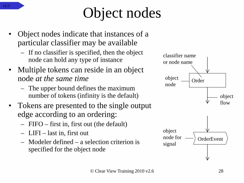
Object nodes• Object nodes indicate that instances of a
particular classifier may be available– If no classifier is specified, then the object
node can hold any type of instance• Multiple tokens can reside in an object
node at the same time– The upper bound defines the maximum
number of tokens (infinity is the default)• Tokens are presented to the single output
edge according to an ordering:– FIFO – first in, first out (the default)– LIFI – last in, first out– Modeler defined – a selection criterion is
specified for the object nodeOrderEvent
Orderobjectnode
objectflow
objectnode for signal
classifier nameor node name
14.9
© Clear View Training 2010 v2.6 29
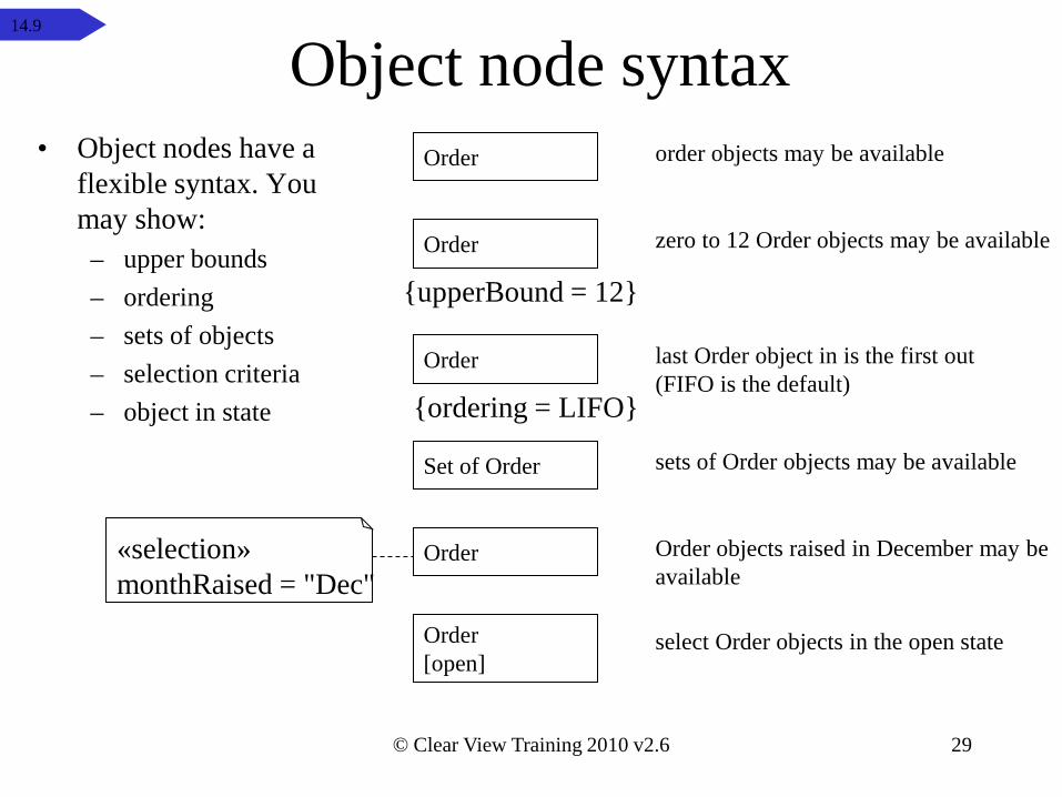
Object node syntax• Object nodes have a
flexible syntax. You may show:
– upper bounds– ordering– sets of objects– selection criteria– object in state
Order objects raised in December may be available
zero to 12 Order objects may be available
Order
Set of Order
Order[open]
Order«selection»monthRaised = "Dec"
order objects may be available
sets of Order objects may be available
select Order objects in the open state
Order
{upperBound = 12}
Order
{ordering = LIFO}
last Order object in is the first out(FIFO is the default)
14.9
© Clear View Training 2010 v2.6 30
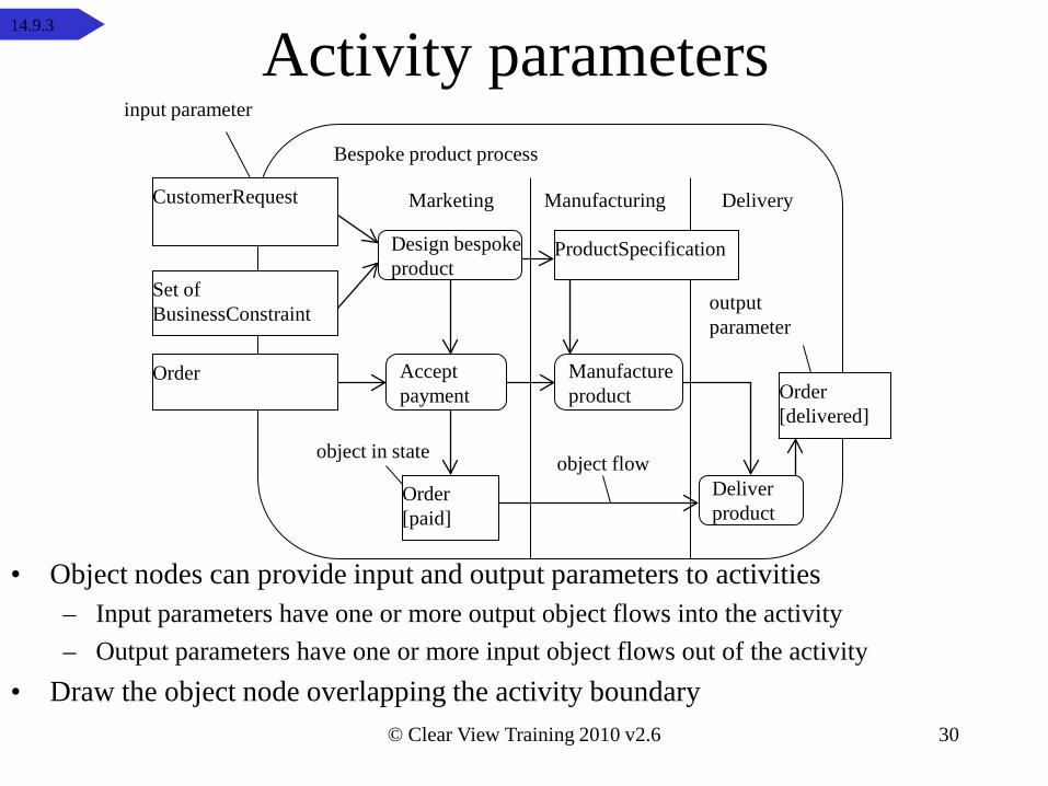
Activity parameters
• Object nodes can provide input and output parameters to activities– Input parameters have one or more output object flows into the activity– Output parameters have one or more input object flows out of the activity
• Draw the object node overlapping the activity boundary
Design bespoke product
Manufactureproduct
Acceptpayment
Deliver product
Marketing Manufacturing Delivery
Order[paid]
CustomerRequest
Set of BusinessConstraint
Order[delivered]
Bespoke product process
Order
input parameter
outputparameter
object flowobject in state
ProductSpecification
14.9.3
© Clear View Training 2010 v2.6 31
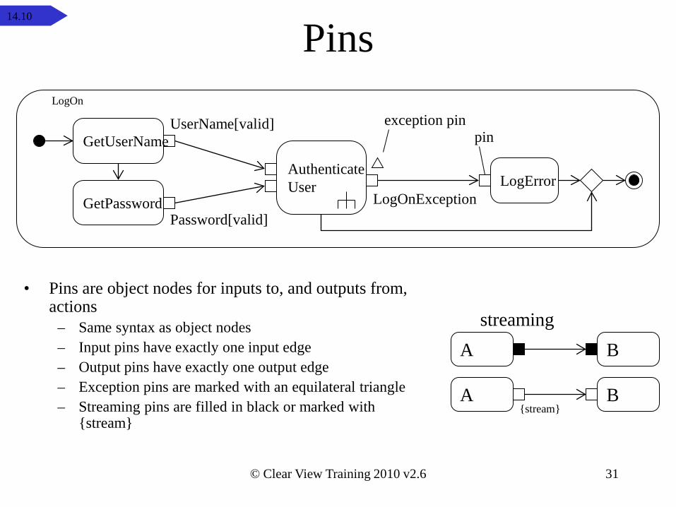
Pins
• Pins are object nodes for inputs to, and outputs from, actions
– Same syntax as object nodes– Input pins have exactly one input edge– Output pins have exactly one output edge– Exception pins are marked with an equilateral triangle– Streaming pins are filled in black or marked with
{stream}
A B
A B{stream}
streaming
GetUserName
GetPassword
UserName[valid]
Password[valid]
AuthenticateUser LogError
LogOnException
LogOn
pinexception pin
14.10
32
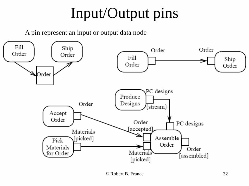
Input/Output pinsA pin represent an input or output data node
© Robert B. France
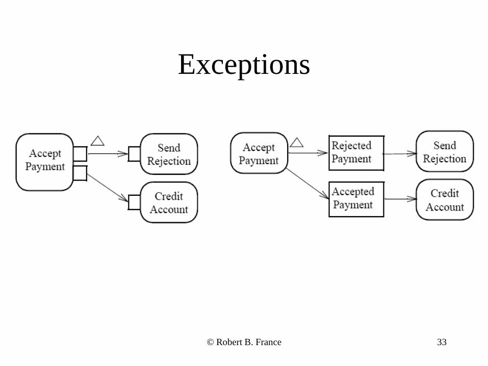
33
Exceptions
© Robert B. France
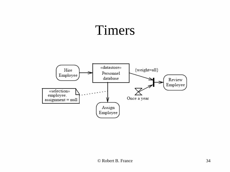
34
Timers
© Robert B. France
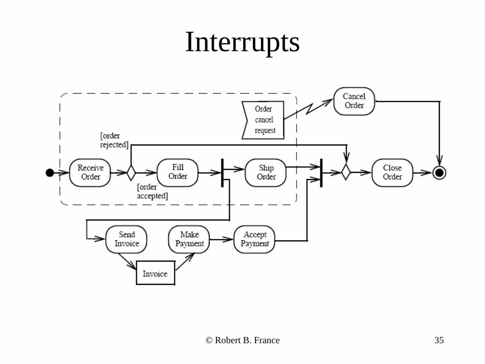
35
Interrupts
© Robert B. France
© Clear View Training 2010 v2.6 36
Summary• We have seen how we can use activity diagrams to model flows of
activities using:– Activities
• Connectors– Activity partitions– Action nodes
• Call action node• Send signal/accept event action node• Accept time event action node
– Control nodes• decision and merge• fork and join
– Object nodes• input and output parameters• pins
14.11