Embed Size (px)
Citation preview
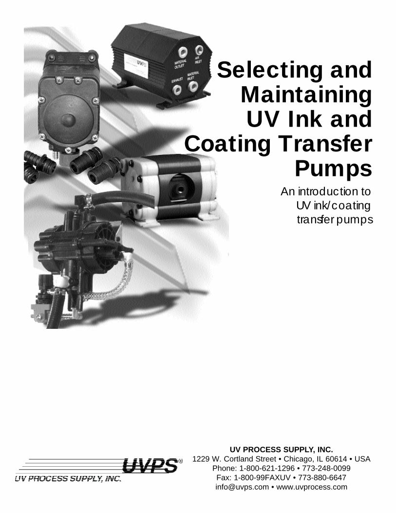
Selecting andMaintaining UV Ink and
Coating TransferPumps
UV PROCESS SUPPLY, INC. 1229 W. Cortland Street • Chicago, IL 60614 • USA
Phone: 1-800-621-1296 • 773-248-0099 Fax: 1-800-99FAXUV • 773-880-6647 [email protected] • www.uvprocess.com
An introduction to UV ink/coating transfer pumps
Table of ContentsI. Introduction page 2
II. Selecting a UV Ink/Coating Pump page 2
III. Types of Pumps page 4
IV. Advantages of the Double-Diaphragm page 5
V. UV Ink and Coating Viscosity page 8
VI. Cavitation page 9
VII. Compressed Air Preparation page 9
VIII. Transfer Line Vibration page 10
IX. Filtration Requirements page 11
X. Clean-up Considerations page 12
XI. Conclusion page 12
XII. Pump Selection page 13
XIII. Pump Accessories page 18
XIV. Pump Glossary page 21
UV Process Supply, Inc. Copyright © 200321
Copyright © 2003 UV Process Supply, Inc.
INTRODUCTION
UV Process Supply is dedicated to promoting safety in the UV curing
workplace. As part of our commitment, we offer a number of
products that offer employees protection against UV ink and coating
contact. While our Latex Disposable Gloves (Item #I004-002/003,
I004-044/048 ), UV Barrier Cream (Item #I002-003), Aprons (Item
#I003-002 ) and Coveralls (Item #I003-007) provide workers front-
line defense, UV ink and coating pumps are critically important to
improving employee safety. By reducing the potential for contact
between the operator and the UV material or chemical being pumped,
the pump can eliminate a number of health hazards that may result
from improper exposure.
When examining the fluid dynamics of UV-curable inks and coatings,
there are a number of pump designs that can be readily used to lift
and transfer these materials from storage to application. Each of
these pumps include specific design features which cause fluid
motion, and which prevent the formation of a vacuum which can
reduce the flow of the pumped material and damage the structure of
the pump.
SELECTING A UV INK/COATING PUMP
There are a wide variety of pump designs available for industrial and
commercial uses. Each pump utilizes a unique design for fluid
transfer, and most can be manufactured with components that are
compatible with UV inks and coatings. Yet, prior to purchasing,
you must:
1. Determine the compatibility of the material to be pumped. UV
curable inks and coatings have a unique chemistry and composition
that requires special handling and pumping needs. They are
comprised of 100% solids, contain no solvents, and can react
chemically with certain materials used in pump manufacture. Such
reactive materials can ultimately change the physical characteristics
of the UV ink or coating so that the material’s performance
attributes change.
All wetted components, defined as parts that come in contact
with the material being pumped, should be made of durable,
non-porous materials. They should also have some level of 2

UV Process Supply, Inc. Copyright © 20034
flexibility as high pumping speeds, cleaning solutions, and pumped
material can cause diaphragms and seals to become brittle and
breakdown over time. All UV Process Supply pumps have
been successfully tested for compatibility with the acrylate
monomers and clean-up solvent typically found in UV ink
and coating applications.
2. Determine the fluid’s characteristics: type and concentration;
temperature; specific gravity; viscosity; solids content.
3. Determine whether fluid characteristics of the pumped material
are chemically compatible with the materials used to construct
the pump.
4. Determine the conditions of operation for the application,
including:
Flow Rate: Calculated in Gallons per Minute(double-diaphragm) or
Liters per Minute (peristaltic). GPM vs. L/min.
Head Pressure: Calculated in feet, PSI or Bar and measured at the
pump, this determines how far and how high material can be
pumped from the pumping source. Remember to calculate the
pressure-building effect that elbows, fittings, quick disconnects,
and nozzles have on the system.
Self-priming: If required, determine how many feet (meters) or
inches (centimeters) there are from fluid level to the pump. For
UV inks and coatings, this is important as air can be drawn through
the pump when a job is complete to clear blockages. This air
flow inhibits polymerization to keep the line clear during
downtime.
Duty cycle: Determine the amount of time the pump is used during
an average production day and week.
5. Select a pump size in reference to the flow rate and pressure as
determined in step 3. Inlet and discharge lines should be the same
size or slightly larger than the pump port sizes.
When selecting your UV ink pumpremember to compensate for pressure-building elbows and fittings. Alsodetermine how far and how high thematerial must be pumped from storageto application. These factors, amoungothers, will help determine the pumpsize required.
3
Copyright © 2003 UV Process Supply, Inc.
6. Determine the application:
A. Standard transfer or recirculation: If standard transfer, then a
standard pump with no switch and no bypass is required. If
recirculation, then a switch or control on the system must be used.
B. On-demand material supply: If required, then a demand (switch)
pump is necessary. The pump will be automatically actuated by the
switch when a valve is opened in the discharge line and will
automatically deactivate the pump when the valve is closed.
Demand pumps should be mounted horizontally for optimal
performance and safety.
C. Continual short-period operation against a partially or fully closed valve:
If required, then a bypass pump is necessary. This pump is fitted
with a bypass valve to allow the fluid to bypass from the high
pressure side to the low pressure side and not damage the pump.
7. Determine the pump’s requirements for port fittings and strainers
and select the appropriate options.
8. Determine cost factors, such as purchase price and maintenance
(clean-up/repair).
TYPES OF PUMPS
There are a variety of pump designs that incorporate different
mechanisms for transferring materials. The pump design most
suitable for transferring UV inks and coatings must consider critical
performance factors such as seizing, shearing and viscosity.
Centrifugal and piston pumps generate heat when the pump’s driving
mechanism contacts the pump’s stationary resistance force, or the
stationary wall against which pressure is built. For centifugal pumps
heat is generated when the impeller vane rotates against the pump
casting. For piston pumps, heat is generated as the piston reciprocates
against the cylinder wall. This repeated motion creates energy and
the heat build-up can cause the ink or coating to polymerize within
the pump chamber. Over time, this polymerized material will cause
the pump to bind and ultimately fail.
4
UV Process Supply, Inc. Copyright © 20036
In addition, any pump which employs a mechanism which shears or
cuts the material as it is being transferred (i.e. a centrifugal’s impeller
vane and its casting outlet), will lower the UV ink or coating’s
viscosity. Such a change will produce a higher flow rate and a variable
film thickness during application. This will affect coverage and final
UV cure as thicker films cure at a different rate (more energy; slower
speeds) than thinner films.
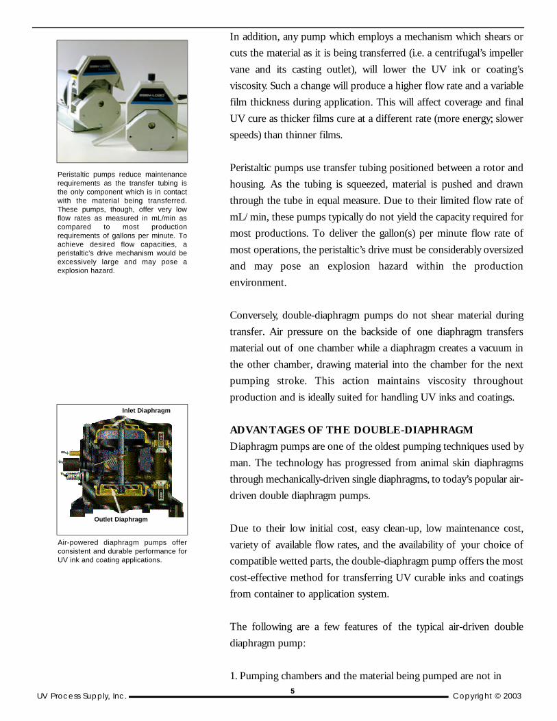
Peristaltic pumps use transfer tubing positioned between a rotor and
housing. As the tubing is squeezed, material is pushed and drawn
through the tube in equal measure. Due to their limited flow rate of
mL/min, these pumps typically do not yield the capacity required for
most productions. To deliver the gallon(s) per minute flow rate of
most operations, the peristaltic’s drive must be considerably oversized
and may pose an explosion hazard within the production
environment.
Conversely, double-diaphragm pumps do not shear material during
transfer. Air pressure on the backside of one diaphragm transfers
material out of one chamber while a diaphragm creates a vacuum in
the other chamber, drawing material into the chamber for the next
pumping stroke. This action maintains viscosity throughout
production and is ideally suited for handling UV inks and coatings.
ADVANTAGES OF THE DOUBLE-DIAPHRAGM
Diaphragm pumps are one of the oldest pumping techniques used by
man. The technology has progressed from animal skin diaphragms
through mechanically-driven single diaphragms, to today’s popular air-
driven double diaphragm pumps.
Due to their low initial cost, easy clean-up, low maintenance cost,
variety of available flow rates, and the availability of your choice of
compatible wetted parts, the double-diaphragm pump offers the most
cost-effective method for transferring UV curable inks and coatings
from container to application system.
The following are a few features of the typical air-driven double
diaphragm pump:
1. Pumping chambers and the material being pumped are not in
Air-powered diaphragm pumps offerconsistent and durable performance forUV ink and coating applications.
Peristaltic pumps reduce maintenancerequirements as the transfer tubing isthe only component which is in contactwith the material being transferred.These pumps, though, offer very lowflow rates as measured in mL/min ascompared to most productionrequirements of gallons per minute. Toachieve desired flow capacities, aperistaltic’s drive mechanism would beexcessively large and may pose aexplosion hazard.
Outlet Diaphragm
Inlet Diaphragm
5
Copyright © 2003 UV Process Supply, Inc.
contact with any close fitting rotary or sliding seals. This makes
double diaphragm pumps ideal for use with UV inks, coatings,
abrasives and slurries.
2. Diaphragm pumps are the only pumps designed for dispensing
purposes. This means that when operating the pump at 60 lbs. of
air pressure, the pump will run until 60 lbs. of pressure is built
up through the transfer line. Once this pressure is established, the
pump will shutdown until additional pressure is required to meet
the 60 lb. requirement. This allows the operator to place a cut-off
valve at the press to control the flow without having to shutdown
the pump. By closing the fluid outlet on a diaphragm pump, the
pump stops. There is no movement, no wear, no overhead, no heat
build-up, and no power consumption, making the pump 100%
energy efficient.
3. Inherently pressure balanced diaphragms always balance air
pressure against the fluid being pumped. The diaphragm acts as a
membrane that separates fluid and air, yet the diaphragm is not
stressed as are members of mechanically driven pumps. Therefore,
pumping efficiency remains constant. And since there are no rotors,
gears, vanes or pistons, there is no gradual decline in performance
due to wear.
4. With diaphragm pumps, there is no foaming or shearing of
material so the material being pumped remains unchanged
following transfer.
5. Capacities are infinitely variable within a specific pump’s
operating range. There is no need to use variable speed motors
or variable drives.
6. Although the pumps deliver large volumes at intermediate
pressures, they can also develop pressures of up to 125 PSI when
substantial pressures are necessary or when high suction lifts
are required.
7. Air-driven double diaphragm pumps can be run dry with only
additional wear to the diaphragm because, unlike centrifugal
pumps, there are no rotary seals or packing glands that need
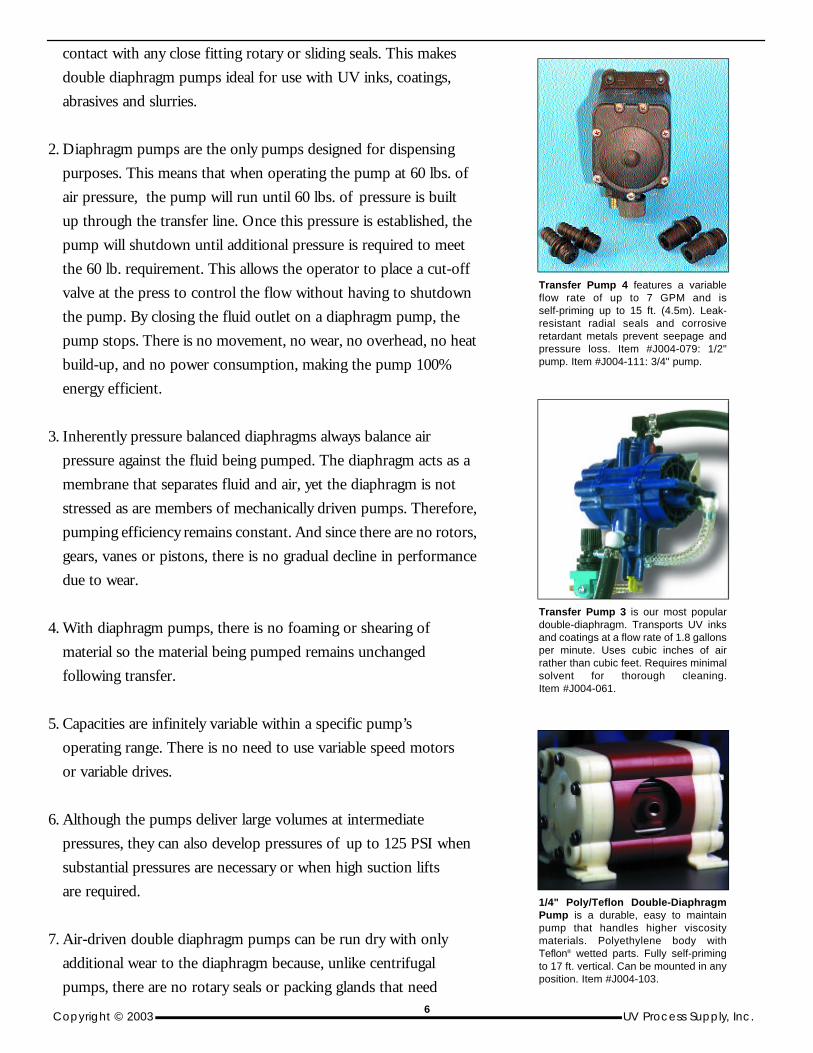
Transfer Pump 4 features a variableflow rate of up to 7 GPM and isself-priming up to 15 ft. (4.5m). Leak-resistant radial seals and corrosiveretardant metals prevent seepage andpressure loss. Item #J004-079: 1/2"pump. Item #J004-111: 3/4" pump.
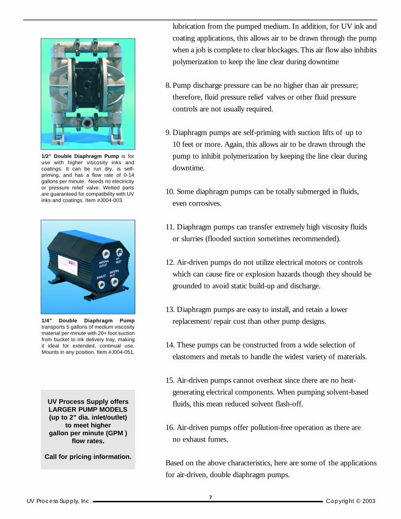
Transfer Pump 3 is our most populardouble-diaphragm. Transports UV inksand coatings at a flow rate of 1.8 gallonsper minute. Uses cubic inches of airrather than cubic feet. Requires minimalsolvent for thorough cleaning.Item #J004-061.
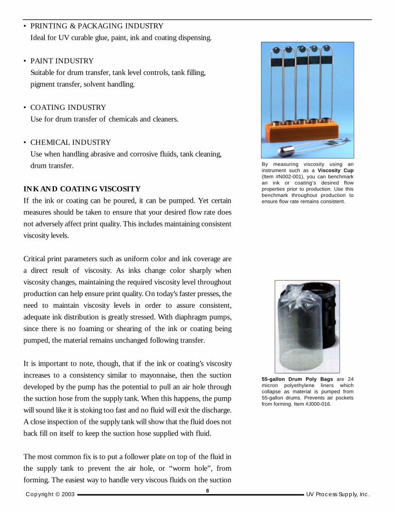
1/4" Poly/Teflon Double-DiaphragmPump is a durable, easy to maintainpump that handles higher viscositymaterials. Polyethylene body withTeflon® wetted parts. Fully self-primingto 17 ft. vertical. Can be mounted in anyposition. Item #J004-103.
6
UV Process Supply, Inc. Copyright © 20038
lubrication from the pumped medium. In addition, for UV ink and
coating applications, this allows air to be drawn through the pump
when a job is complete to clear blockages. This air flow also inhibits
polymerization to keep the line clear during downtime
8. Pump discharge pressure can be no higher than air pressure;
therefore, fluid pressure relief valves or other fluid pressure
controls are not usually required.
9. Diaphragm pumps are self-priming with suction lifts of up to
10 feet or more. Again, this allows air to be drawn through the
pump to inhibit polymerization by keeping the line clear during
downtime.
10. Some diaphragm pumps can be totally submerged in fluids,
even corrosives.
11. Diaphragm pumps can transfer extremely high viscosity fluids
or slurries (flooded suction sometimes recommended).
12. Air-driven pumps do not utilize electrical motors or controls
which can cause fire or explosion hazards though they should be
grounded to avoid static build-up and discharge.
13. Diaphragm pumps are easy to install, and retain a lower
replacement/repair cost than other pump designs.
14. These pumps can be constructed from a wide selection of
elastomers and metals to handle the widest variety of materials.
15. Air-driven pumps cannot overheat since there are no heat-
generating electrical components. When pumping solvent-based
fluids, this mean reduced solvent flash-off.
16. Air-driven pumps offer pollution-free operation as there are
no exhaust fumes.
Based on the above characteristics, here are some of the applications
for air-driven, double diaphragm pumps.
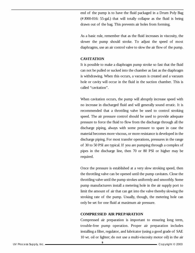
1/2" Double Diaphragm Pump is foruse with higher viscosity inks andcoatings. It can be run dry, is self-priming, and has a flow rate of 0-14gallons per minute. Needs no electricityor pressure relief valve. Wetted partsare guaranteed for compatibility with UVinks and coatings. Item #J004-003.
1/4" Double Diaphragm Pumptransports 5 gallons of medium viscositymaterial per minute with 20+ foot suctionfrom bucket to ink delivery tray, makingit ideal for extended, continual use.Mounts in any position. Item #J004-051.
UV Process Supply offersLARGER PUMP MODELS (up to 2” dia. inlet/outlet)
to meet higher gallon per minute (GPM )
flow rates.
Call for pricing information.
7
Copyright © 2003 UV Process Supply, Inc.
• PRINTING & PACKAGING INDUSTRY
Ideal for UV curable glue, paint, ink and coating dispensing.
• PAINT INDUSTRY
Suitable for drum transfer, tank level controls, tank filling,
pigment transfer, solvent handling.
• COATING INDUSTRY
Use for drum transfer of chemicals and cleaners.
• CHEMICAL INDUSTRY
Use when handling abrasive and corrosive fluids, tank cleaning,
drum transfer.
INK AND COATING VISCOSITY
If the ink or coating can be poured, it can be pumped. Yet certain
measures should be taken to ensure that your desired flow rate does
not adversely affect print quality. This includes maintaining consistent
viscosity levels.
Critical print parameters such as uniform color and ink coverage are
a direct result of viscosity. As inks change color sharply when
viscosity changes, maintaining the required viscosity level throughout
production can help ensure print quality. On today’s faster presses, the
need to maintain viscosity levels in order to assure consistent,
adequate ink distribution is greatly stressed. With diaphragm pumps,
since there is no foaming or shearing of the ink or coating being
pumped, the material remains unchanged following transfer.
It is important to note, though, that if the ink or coating’s viscosity
increases to a consistency similar to mayonnaise, then the suction
developed by the pump has the potential to pull an air hole through
the suction hose from the supply tank. When this happens, the pump
will sound like it is stoking too fast and no fluid will exit the discharge.
A close inspection of the supply tank will show that the fluid does not
back fill on itself to keep the suction hose supplied with fluid.
The most common fix is to put a follower plate on top of the fluid in
the supply tank to prevent the air hole, or “worm hole”, from
forming. The easiest way to handle very viscous fluids on the suction
55-gallon Drum Poly Bags are 24micron polyethylene liners whichcollapse as material is pumped from55-gallon drums. Prevents air pocketsfrom forming. Item #J000-016.
By measuring viscosity using aninstrument such as a Viscosity Cup(Item #N002-001), you can benchmarkan ink or coating’s desired flowproperties prior to production. Use thisbenchmark throughout production toensure flow rate remains consistent.
8
UV Process Supply, Inc. Copyright © 2003
end of the pump is to have the fluid packaged in a Drum Poly Bag
(#J000-016: 55-gal.) that will totally collapse as the fluid is being
drawn out of the bag. This prevents air holes from forming.
As a basic rule, remember that as the fluid increases in viscosity, the
slower the pump should stroke. To adjust the speed of most
diaphragms, use an air control valve to slow the air flow of the pump.
CAVITATION
It is possible to make a diaphragm pump stroke so fast that the fluid
can not be pulled or sucked into the chamber as fast as the diaphragm
is withdrawing. When this occurs, a vacuum is created and a vacuum
hole or cavity will occur in the fluid in the suction chamber. This is
called “cavitation”.
When cavitation occurs, the pump will abruptly increase speed with
no increase in discharged fluid and will generally sound erratic. It is
recommended that a throttling valve be used to control stroking
speed. The air pressure control should be used to provide adequate
pressure to force the fluid to flow from the discharge through all the
discharge piping, always with some pressure to spare in case the
material becomes more viscous, or more resistance is developed in the
discharge piping. For most transfer operations, pressures in the range
of 30 to 50 PSI are typical. If you are pumping through a complex of
pipes in the discharge line, then 70 or 80 PSI or higher may be
required.
Once the pressure is established at a very slow stroking speed, then
the throttling valve can be opened until the pump cavitates. Close the
throttling valve until the pump strokes uniformly and smoothly. Some
pump manufacturers install a metering hole in the air supply port to
limit the amount of air that can get into the valve thereby slowing the
stroking rate of the pump. Usually, though, the metering hole can
only be set for one fluid at maximum air pressure.
COMPRESSED AIR PREPARATION
Compressed air preparation is important to ensuring long term,
trouble-free pump operation. Proper air preparation includes
installing a filter, regulator, and lubricator (using a good grade of SAE
10 wt. oil or lighter; do not use a multi-viscosity motor oil) in the air9
Copyright © 2003 UV Process Supply, Inc.
supply line. The oil is usually fed at a rate of approximately one drop
every 20 SCFM. The filter should remove dirt as well as water from
the supply air. However, the filter should be emptied or left open to
bleed the trapped water out of the system.
To check lubrication quality of most diaphragm pumps, remove the
muffler cover to expose the screen. The screen should have a thin,
light film of oil. If the oil is heavy, gummy or milky-colored, it is
probably of too high a viscosity or contains water. Too high viscosity
oil or water mixed in with the oil will cause the valve to shift slowly or
erratically. If the air is contaminated with dirt, this will also show on
the screen.
Refrigerated, or chilled, air is also recommended as it removes water
vapor from the air and further extends pump life.
TRANSFER LINE VIBRATION
For all practical purposes, UV inks and coatings are not compressible.
This means they will neither absorb nor cushion a pulse or surge
created by a pump’s action, but instead will transmit the energy from
one form to another. Thus, pulsation and/or surge can occur when
liquid is pulsated, stopped, or turned.
Diaphragm pumps move liquid by trapping and then expelling
discrete units of that liquid. The pumped material actually comes to a
complete stop every time the pump shifts, which can occur up to
several hundred times per minute. This start-stop action creates spikes
in the manner of high amplitude, low frequency pulses.
To control pulsation and surge, and to ensure that ink or coating
flows consistently, there are several control methods that can be
effectively employed:
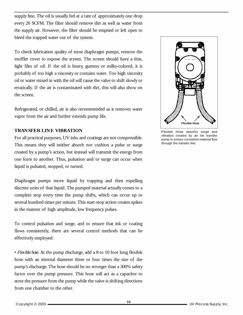
• Flexible hose. At the pump discharge, add a 8 to 10 foot long flexible
hose with an internal diameter three or four times the size of the
pump’s discharge. The hose should be no stronger than a 300% safety
factor over the pump pressure. This hose will act as a capacitor to
store the pressure from the pump while the valve is shifting directions
from one chamber to the other.
Flexible Hose absorbs surge andvibration created by an ink transferpump to ensure consistent material flowthrough the transfer line.
Flexible Hose
10

UV Process Supply, Inc. Copyright © 2003
After the oversized hose, install a transfer line that reduces the pipe
size to suit the application. A throttling valve should be placed in the
discharge line at this point. Additional flow control valves may be
used further downstream as the application requires.
UV Process Supply’s UV transfer hose (Item #J008-001: 3/8” hose;
#J008-005: 1/2” hose) is fiber-reinforced rubber/EPDM to handle
the pressures built up during use. Its opaque composition prevents
ambient UV light sources, such as sunlight and fluorescent lamps,
from causing the UV materials to polymerize during transfer.
Typical transfer tubing is made of transparent vinyl material. Vinyl is
incompatible with UV materials and any transparent hose transmits
UV energy which may cause the UV material to polymerize during
transfer. UV Process Supply offers a UV-compatible, semi-opaque
silicone tubing (Item #J004-074C: 1/4” silicone tubing) for use with
peristaltic applications.
• Surge suppressors (Item #J004-052: 1/2”; #J004-053: 1/4”). Used to
absorb pressure surges caused by quick-closing va1ves, long vertical
runs and pump start-up/shut-down. They act directly to equalize or
balance the pulses generated by the pump, and generally provide an
economical, efficient and safe method for controlling pulsation
and surge.
FILTRATION REQUIREMENTS
Keeping your ink pumps contaminate-free helps extend the pump’s
overall life span and the life of the pump’s wetted components. Even
small contaminates can be harmful to diaphragms and seals.
Therefore, all inks and coatings should be properly filtered before
being pumped.
UV Process Supply’s line of Disposable Strainers (Item #J012-014 -
J012-023) for 1 and 5-gallon batches of inks, coatings, resins,
pigments, additives, solvents or any other liquids provide a clean,
hands-free filtering. These products restore the quality and
consistency of inks, coatings and raw materials by removing settled
contaminants and eliminate any downtime associated with clogged or
damaged pumps or pump lines due to contaminated ink or coating.
Inlet Strainers (Item #J004-013) are recommended on all applications
Inks and coatings should always beproperly strained and/or filtered prior topumping to ensure pump damage isminimized.
In-line filters
Regular pump maintenance includesflushing the pump with a compatiblecleaner, such as pH6 Liquid Soap, andperiodically disassembling the pumpand replacing seals and diaphragms.Such maintenance will extend the life ofthe pump body and components.
Surge suppressors are designedspecifically to reduce pulsation createdwithin fluid pumping lines. By installing asuppressors as close as possible to thepump source, most pulsation can bedampened to ensure consistent flow.
1- and 5-galloncontainer strainers
11
Copyright © 2003 UV Process Supply, Inc.
to prevent clogging of the valves.
CLEAN-UP CONSIDERATIONS
Regularly scheduled pump maintenance can preserve the integrity of
the pump’s wetted parts and overall operating performance.
Therefore, every double-diaphragm pump must be regularly
inspected, cleaned and occasionally retightened to ensure reliable
long-term performance.
For cleaning UV inks and coatings from internal pump parts, pump
pH Liquid Soap (Item #I001-007) through pump chamber and allow
to soak. This soap will effectively dissolve UV resins and pigments
remaining within the chamber. After soaking, flush the pump with
water or a low-VOC solvent. As double-diaphragm pumps are
compact in size, they require less clean-up chemicals for maintaining
reliable performance.
When replacing worn internal components, UV Process Supply also
maintains Repair Kits for each of its Con-Trol-CureTM pumps.
CONCLUSION
Selecting a dependable UV ink and coating pump requires an
understanding of the unique characteristics of the materials being
transferred. Choosing a pump which maintains the integrity of the
material being pumped and which incorporates wetted parts that are
compatible with UV chemistry is critical to obtaining reliable
performance.
As we have shown, the air-driven double-diaphragm offers a clear
advantage over other pump designs for safely handling UV materials.
It has proven itself through years of consistent performance in
various UV ink and coating applications, and remains the primary
pump for most users of UV curing chemistries.
12
UV Process Supply, Inc. Copyright © 2003
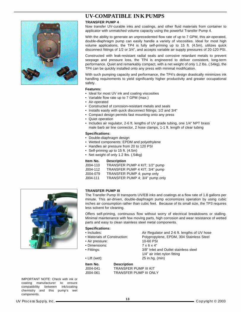
UV-COMPATIBLE INK PUMPSTRANSFER PUMP 4Now transfer UV-curable inks and coatings, and other fluid materials from container toapplicator with unmatched volume capacity using the powerful Transfer Pump 4.
With the ability to generate an unprecedented flow rate of up to 7 GPM, this air-operated,double-diaphragm pump can easily handle a variety of viscosities. Ideal for most highvolume applications, the TP4 is fully self-priming up to 15 ft. (4.5m), utilizes quickdisconnect fittings of 1/2 or 3/4”, and accepts variable air supply pressures of 20-120 PSI.
Constructed with leak-resistant radial seals and corrosive retardant metals to preventseepage and pressure loss, the TP4 is engineered to deliver consistent, long-termperformance. Quiet and remarkably compact, with a net weight of only 1.2 lbs. (.54kg), theTP4 can be quickly installed onto any press with minimal modification.
With such pumping capacity and performance, the TP4’s design drastically minimizes inkhandling requirements to yield significantly higher productivity and greater occupationalsafety.
Features:• Ideal for most UV ink and coating viscosities• Variable flow rate up to 7 GPM (max.)• Air-operated• Constructed of corrosion-resistant metals and seals• Installs easily with quick disconnect fittings; 1/2 and 3/4”• Compact design permits fast mounting onto any press• Quiet operation• Includes air regulator, 2-6 ft. lengths of UV grade tubing, one 1/4” NPT brass
male barb air line connector, 2 hose clamps, 1-1 ft. length of clear tubing
Specifications:• Double-diaphragm design• Wetted components: EPDM and polyethylene• Handles air pressure from 20 to 120 PSI• Self-priming up to 15 ft. (4.5m)• Net weight of only 1.2 lbs. (.54kg)
Item No. Description J004-110 TRANSFER PUMP 4 KIT; 1/2” pump J004-112 TRANSFER PUMP 4 KIT; 3/4” pump J004-079 TRANSFER PUMP 4; pump only J004-111 TRANSFER PUMP 4; 3/4” pump only
TRANSFER PUMP IIIThe Transfer Pump III transports UV/EB inks and coatings at a flow rate of 1.8 gallons perminute. This air-driven, double-diaphragm pump economizes operation by using cubicinches air consumption rather than cubic feet. Because of its small size, the TP3 requiresless solvent for cleaning.
Offers self-priming, continuous flow without worry of electrical breakdowns or stalling.Minimal maintenance with few moving parts, high corrosion and wear resistance of wettedparts and easy to clean stainless steel metal components.
Specifications:• Includes: Air Regulator and 2-6 ft. lengths of UV hose• Materials of Construction: Polypropylene, EPDM, 304 Stainless Steel• Air pressure: 10-60 PSI• Dimensions: 7 x 6 x 4”• Fittings: 3/8” Inlet and Outlet stainless steel
1/4” air inlet nylon fitting• Lift (wet): 25 in.hg. (min)
Item No. DescriptionJ004-041 TRANSFER PUMP III KITJ004-061 TRANSFER PUMP III ONLY
IMPORTANT NOTE: Check with ink orcoating manufacturer to ensurecompatibility between ink/coatingchemistry and this pump’s wetcomponents.
13
Copyright © 2003 UV Process Supply, Inc.
TRANSFER PUMP 3V KITSimilar in size and capabilities to the popular Transfer Pump III, the 3V utilizescomponents made of Viton® for greater resistance to most solvents and inks. Featuresof 1.8 GPM flow rate, easy cleaning, and universal mounting.
Specifications:• Includes: Air Regulator and 2-6 ft. lengths of UV hose• Materials: Viton®, EPDM, 304 Stainless Steel• Air pressure: 10-60 PSI• Dimensions: 7 x 6 x 4”• Fittings: 3/8” Inlet and Outlet stainless steel; 1/4” air inlet nylon elbow fitting• Lift (wet): 25 in.hg. (min)
Item No. Description J004-071 TRANSFER PUMP 3V KITJ004-072 TRANSFER PUMP 3V ONLY J004-073 TRANSFER PUMP 3V REPAIR KIT
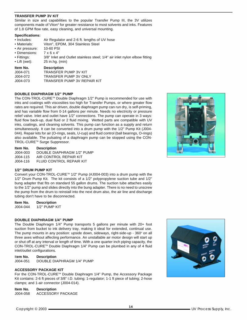
DOUBLE DIAPHRAGM 1/2” PUMPThe CON-TROL-CURETM Double Diaphragm 1/2” Pump is recommended for use withinks and coatings with viscosities too high for Transfer Pumps, or where greater flowrates are required. This air driven, double diaphragm pump can run dry, is self-priming,and has variable flow from 0-14 gallons per minute. Needs no electricity or pressurerelief valve. Inlet and outlet have 1/2” connections. The pump can operate in 3 ways:fluid flow back-up, dual fluid or 2 fluid mixing. Wetted parts are compatible with UVinks, coatings, and cleaning solvents. This pump can function as a supply and returnsimultaneously. It can be converted into a drum pump with the 1/2” Pump Kit (J004-044). Repair kits for air (O-rings, seals, U-cup) and fluid control (ball bearings, O-rings)also available. The pulsating of a diaphragm pump can be stopped using the CON-TROL-CURETM Surge Suppressor.
Item No. Description J004-003 DOUBLE DIAPHRAGM 1/2” PUMP J004-115 AIR CONTROL REPAIR KIT J004-116 FLUID CONTROL REPAIR KIT
1/2” DRUM PUMP KIT Convert your CON-TROL-CURETM 1/2” Pump (#J004-003) into a drum pump with the1/2” Drum Pump Kit. The kit consists of a 1/2” polypropylene suction tube and 1/2”bung adapter that fits on standard 55 gallon drums. The suction tube attaches easilyto the 1/2” pump and slides directly into the bung adapter. There is no need to unscrewthe pump from the drum to reinstall into the next drum also, the air line and dischargetubing don’t have to be disconnected.
Item No. Description J004-044 1/2” PUMP KIT
DOUBLE DIAPHRAGM 1/4” PUMP The Double Diaphragm 1/4” Pump transports 5 gallons per minute with 20+ footsuction from bucket to ink delivery tray, making it ideal for extended, continual use.The pump mounts in any position: upside down, sideways, right-side-up - 360o on allthree axes without affecting performance. An unstallable air motor design will start upor shut off at any interval or length of time. With a one quarter inch piping capacity, theCON-TROL-CURETM Double Diaphragm 1/4” Pump can be plumbed in any of 4 fluidinlet/outlet configurations.
Item No. Description J004-051 DOUBLE DIAPHRAGM 1/4” PUMP
ACCESSORY PACKAGE KITFor the CON-TROL-CURETM Double Diaphragm 1/4” Pump, the Accessory PackageKit contains: 2-6 ft pieces of 3/8” I.D. tubing; 1-regulator; 1-1 ft piece of tubing; 2-hoseclamps; and 1-air connector (J004-014).
Item No. Description J004-058 ACCESSORY PACKAGE
14

1/4” POLY/TEFLON DOUBLE DIAPHRAGM PUMP Durable, easy to maintain double diaphragm pump handles tough, heavy viscosity fluids.Polyethylene construction with Teflon® seals offers resistance to solvents and UV inks andcoatings. Pump features leak-free, non-stalling operation, fully self-priming up to 17 ft.vertical, and can mounted in any operating position.
Features:• Air-powered, spark-free operation• Non-stalling• Self-priming; 17 ft. vertical dry suction• Runs dry• Variable flow rate• Pumps in any mounting position• Reversible fluid inlet/outlet positions• Up 30 fewer components than competitive pumps
Specifications:• Seals: Teflon®
• Construction: Polypropylene• Capacity: Adjustable 0 to 4.3 GPM (16.3l/min.)• Oper. Temp.: 150oF (66oC)• Max. Air: 100 PSI (6.8 bar)• Weight: 5 lbs.• Max. Solids: Up to 1/16”• Air Inlet/Outlet: 1/4” NPSF Female• Fluid Inlet/Discharge: 1/4” NPSF• Dims (LxWxH): 7.50 x 5.50 x 5.34”
(190.50 x 139.70 x 135.64mm)
Item No. Description J004-103 1/4” POLY/TEFLON DOUBLE DIAPHRAGM PUMP
DUPLEX-DIAPHRAGM ELECTRIC PUMPSWhen pneumatic pumps are not an option, these electric-powered diaphragm pumps offerautomatic control and operate only when liquid flow is required.
Duplex diaphragm design eliminates troublesome shaft seals. Excellent self-primingcapability allows pump positioning above liquid. Corrosion-resistant polypropyleneconstruction with no metal parts in contact with liquid being pumped. Handles small foreignparticles such as resin, dust, dirt, etc. Recommended use with in-line strainer.
Must be properly grounded to prevent electrical shock. Supplied with grounding conductorand grounding-type attachment plug. IMPORTANT: Not intended for high flash point fluids(i.e. solvents, etc.).
Specifications:• Pump design: Duplex diaphragm• Materials: Housing:Reinforced polypropylene
Elastomers: Santoprene, Viton®
• Pressure: Off @ 60 psi (4.1 bar); On @ 40 psi (2.8 bar)• Temperature: Min. = 45oF (70C); Max.= 160o F (71oC)• Ports: 3/8 NPT• Motor: 115 VAC, 50/60 cycle• Current: 0.55 A (max.)• Weight: 4 lbs. (1.8kg)
Item No. Description J004-095 3/8” DUPLEX DIAPHRAGM ELEC. PUMP W/SANTOPRENE SEALSJ004-096 3/8” DUPLEX DIAPHRAGM ELEC. PUMP W/ VITON® SEALS
UV Process Supply, Inc. Copyright © 200315

5 GALLON DISPENSING SYSTEMHigh-powered ink pump system attaches to most 5 gallon containers for meteringpurposes or for transferring inks and coatings. Handles low and high flow rateswith gentle, smooth pumping action. System features polypropylene-encasedpump with 7 GPM max. flow rate attached to 5 gal. pail cover. Complete withsyphon tube, quick disconnect fitting, grounding wire, clamp.
Specifications:• Max. fluid pressure: 100 psi (7 bar)• Max. pump speed: 330 cpm• Max. suction lift: 12 ft. (3.7m) dry; 21 ft. (6.4m) wet• Air pressure Range: 15 - 100 psi (1-7 bar)• Operating temperature: 40-150oF (4.4 - 65.5oC)
Item No. Description J004-097 5-GAL. DISPENSING SYSTEM
WALL-MOUNTED SPRAY SYSTEMLightweight and compact wall-mount pump ideal for in-plant spraying operations,such as adhesive application or woodworking. Color changes require only quicksolvent-flush. Air-operated diaphragm pump providing 7 GPM flow rate.Grounded acetal construction with Teflon diaphragms is compatible withwaterborne paints, solvents and petroleum-based solvents. Includes drum/bungsuction kit, air and fluid hoses, and wall bracket.
Specifications:• Air to fluid pressure: 1:1• Max. fluid pressure: 100 psi (7 bar)• Max pump speed: 330 cycles/min.• Max. air usage: 5.5 scfm• Air pressure range: 15-100 psi (1-7 bar)• Operating temperature: 40-150oF (4.4-65.5oC)• Max. lift: 7 ft (2.1m) dry; 12 ft. (3.7m) wet
Item No. Description J004-099 WALL-MOUNTED SPRAY SYSTEM
Viton® is a registered trademark of DuPont Dow Elastomers.
SURGE SUPPRESSORSDouble Diaphragm Pumps offer many benefits over most other types ofreciprocating pumps. They do however, present the drawback of pulsation. Thesesurges or pulsations can damage pipes, fittings, couplings and valves.
For a steady stream, the two CON-TROL-CURETM Surge Suppressor models (for1/4” and 1/2” flexible air hoses) act as shock absorbers to cushion the effects ofpulsating flow. Basically constructed as closed chambers, they each contain anelastomer bladder inside. The bladder separates a compressed air cushion on the top from the pumped liquid on the bottom.
To control surges from delivery discharges, the Surge Suppressor should beinstalled at the pump’s discharge connection. The closer to the discharge, thebetter the dampening effect.
Item No. Description J004-052 1/2” SURGE SUPPRESSOR J004-053 1/4” SURGE SUPPRESSOR
Copyright © 2003 UV Process Supply, Inc. 16
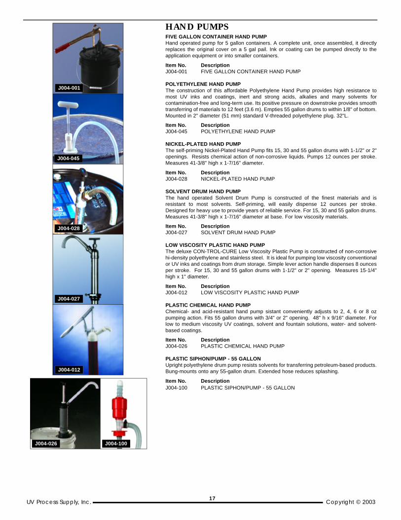
HAND PUMPSFIVE GALLON CONTAINER HAND PUMP Hand operated pump for 5 gallon containers. A complete unit, once assembled, it directlyreplaces the original cover on a 5 gal pail. Ink or coating can be pumped directly to theapplication equipment or into smaller containers.
Item No. DescriptionJ004-001 FIVE GALLON CONTAINER HAND PUMP
POLYETHYLENE HAND PUMP The construction of this affordable Polyethylene Hand Pump provides high resistance tomost UV inks and coatings, inert and strong acids, alkalies and many solvents forcontamination-free and long-term use. Its positive pressure on downstroke provides smoothtransferring of materials to 12 feet (3.6 m). Empties 55 gallon drums to within 1/8" of bottom.Mounted in 2" diameter (51 mm) standard V-threaded polyethylene plug. 32"L.
Item No. DescriptionJ004-045 POLYETHYLENE HAND PUMP
NICKEL-PLATED HAND PUMP The self-priming Nickel-Plated Hand Pump fits 15, 30 and 55 gallon drums with 1-1/2" or 2"openings. Resists chemical action of non-corrosive liquids. Pumps 12 ounces per stroke.Measures 41-3/8" high x 1-7/16" diameter.
Item No. Description J004-028 NICKEL-PLATED HAND PUMP
SOLVENT DRUM HAND PUMP The hand operated Solvent Drum Pump is constructed of the finest materials and isresistant to most solvents. Self-priming, will easily dispense 12 ounces per stroke.Designed for heavy use to provide years of reliable service. For 15, 30 and 55 gallon drums.Measures 41-3/8" high x 1-7/16" diameter at base. For low viscosity materials.
Item No. Description J004-027 SOLVENT DRUM HAND PUMP
LOW VISCOSITY PLASTIC HAND PUMP The deluxe CON-TROL-CURE Low Viscosity Plastic Pump is constructed of non-corrosivehi-density polyethylene and stainless steel. It is ideal for pumping low viscosity conventionalor UV inks and coatings from drum storage. Simple lever action handle dispenses 8 ouncesper stroke. For 15, 30 and 55 gallon drums with 1-1/2" or 2" opening. Measures 15-1/4"high x 1" diameter.
Item No. Description J004-012 LOW VISCOSITY PLASTIC HAND PUMP
PLASTIC CHEMICAL HAND PUMPChemical- and acid-resistant hand pump sistant conveniently adjusts to 2, 4, 6 or 8 ozpumping action. Fits 55 gallon drums with 3/4" or 2" opening. 48" h x 9/16" diameter. Forlow to medium viscosity UV coatings, solvent and fountain solutions, water- and solvent-based coatings.
Item No. Description J004-026 PLASTIC CHEMICAL HAND PUMP
PLASTIC SIPHON/PUMP - 55 GALLONUpright polyethylene drum pump resists solvents for transferring petroleum-based products.Bung-mounts onto any 55-gallon drum. Extended hose reduces splashing.
Item No. Description J004-100 PLASTIC SIPHON/PUMP - 55 GALLON
UV Process Supply, Inc. Copyright © 2003
J004-001
J004-045
J004-028
J004-027
J004-012
J004-026 J004-100
17
Copyright © 2003 UV Process Supply, Inc.
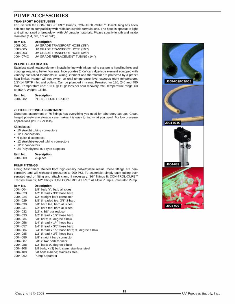
PUMP ACCESSORIESTRANSPORT HOSE/TUBINGFor use with the CON-TROL-CURETM Pumps, CON-TROL-CURETM Hose/Tubing has beenselected for its compatibility with radiation curable formulations. The hose is opaque to lightand will not swell or breakdown with UV curable materials. Please specify length and insidediameter (1/4, 3/8, 1/2 or 3/4").
Item No. Description J008-001 UV GRADE TRANSPORT HOSE (3/8") J008-005 UV GRADE TRANSPORT HOSE (1/2") J008-003 UV GRADE TRANSPORT HOSE (3/4") J004-074C UV GRADE REPLACEMENT TUBING (1/4")
IN-LINE FLUID HEATER Stainless steel heating element installs in-line with ink pumping system to handling inks andcoatings requiring better flow rate. Incorporates 2 KW cartridge-type element equipped withvariably controlled thermostatic. Wiring, element and thermostat are protected by a presetheat limiter. Heater will not switch on until temperature level exceeds room temperature.1/2"-14 NPTF inlet and outlets. Can be plumbed in a row. Prewired for 120, 240 and 480VAC. Temperature rise: 100 F @ 15 gallons per hour recovery rate. Temperature range: 60to 250 F. Weight: 18 lbs.
Item No. Description J004-082 IN-LINE FLUID HEATER
76 PIECE FITTING ASSORTMENTGenerous assortment of 76 fittings has everything you need for laboratory set-ups. Clear,hinged polystyrene storage case makes it is easy to find what you need. For low pressureapplications (20 PSI or less).
Kit includes:• 10 straight tubing connectors• 12 T connectors• 6 quick disconnects• 12 straight-stepped tubing connectors• 12 Y connectors• 24 Polyethylene cup-type stoppers
Item No. Description J004-009 76-piece
PUMP FITTINGS Fitting Assortment Molded from high-density polyethylene resins, these fittings are non-corrosive and will withstand pressures to 200 PSI. To assemble, simply push tubing overserrated end of fitting and attach clamp if necessary. 3/8" fittings fit CON-TROL-CURETM
Transfer Pumps; 1/2" fittings fit the CON-TROL-CURETM All Flow Pump & Peristaltic Pump.
Item No. DescriptionJ004-004 3/8" barb 'Y'; barb all sidesJ004-023 1/2" thread x 3/4" hose barb J004-024 1/2" straight barb connector J004-029 3/8" threaded tee; 3/8" 2-barbJ004-030 3/8" barb tee; barb all sidesJ004-031 1/2" barb tee; barb all sidesJ004-032 1/2" x 3/8" bar reducerJ004-033 1/2" thread x 1/2" hose barb J004-034 3/8" barb; 90 degree elbow J004-056 1/4" thread x 1/4" hose barbJ004-057 1/4" thread x 3/8" hose barb J004-084 3/4" thread x 1/2" hose barb; 90 degree elbow J004-085 1/2" thread x 3/8" hose barb J004-086 3/8" straight barb connector J004-087 3/8" x 1/4" barb reducerJ004-088 1/2" barb; 90 degree elbowJ004-108 3/8 barb; x (3) barb stem; stainless steelJ004-109 3/8 barb U-bend; stainless steelJ004-062 Pump Separator
J008-001/003/005
J004-074C
J004-082
J004-009
18

IN-LINE STRAINER CON-TROL-CURETM In-Line Strainer provides pump protection, nozzle protection, or can beused for most applications where contaminants need to be removed in air or liquid lines.Molded of durable plastic which is resistant to solvents and UV coatings, the strainers arereinforced with tough stainless steel ferrules.Sediment is collected inside the screen forultimate protection.
Diaphram pumps contain four valves which open and close with each pump stroke. Evensmall amounts of particulate matter will impede valve action and shorten pump life. Pumpsfitted with the In-Line Strainer have been observed to last longer and operate with lessmaintenence. UV Process Supply recommends the In-Line Strainer for all 1/4" DoubleDiaphram and Transfer Pump III installations.
Item No. Description J004-013 IN-LINE STRAINER
IN-LINE FILTER DRYER New disposable filter/dryer is compact, lightweight, and functions in both directions. It canbe installed right at the point of use. The clear housing unit removes all traces of water, oiland dirt. 1/4 npt male x female thread. 125 PSI. Compact 3-3/4" length.
Item No. Description J004-089 IN-LINE FILTER DRYER
HIGH-FLOW QUICK DISCONNECT COUPLING Chemical-resistant polypropylene for 1/2" ID tube size. Large flow capacity with small,lightweight body size. Half the cost of bulkier brass or stainless couplings. Ideal for waterand solvent-filtration.
Item No. DescriptionJ004-090 High Flow Disconnect Coupling; 1/2" body w/insert
HOSE CLAMPAll stainless-steel micro-band for securing 1" O.D. nominal hose sizes. Fits hose diameterrange of 11/16 to 1-1/2". 1/2" band width. Perfect for all UVPS double-diaphragm pumps.
Item No. Description J004-091 Hose Clamp; 1/2" wide; 1" nominal
NYLON HOSE CLAMPOne piece nylon (perfect for water, solvent, gas, etc.). Simply squeegee the serrated edgesto edge and twist to release. Temperature range from -60 to 250oF.
Item No. Size/Range J004-092 1/2"; .538 to .608" J004-093 3/8"; .410 to .468"J004-094 1/4"; .246 to .290"
TUBE CLAMP This snap grip Tube Clamp secures tubing and hose in seconds. Snap shut with pliers.Secure, safe and economical. Simple twist action with pliers removes clamp. Made oftough, durable nylon. Hose size 3/4".
Item No. DescriptionJ004-021 Tube Clamp
PINCH CLAMPFor flexible plastic tubing. Up to 12 position control with one-hand operation. Ratchetthrottles flow evenly down to complete closure. Plastic construction will not distort orcorrode. Fine or coarse teeth adjustment. 3/4" tube diameter
Item No. DescriptionJ004-022 PINCH CLAMP; 3/4" O.D.
STAINLESS STEEL BALL VALVES 3/8 and 1/4" heavy-duty, in-line ball valves feature 303 stainless steel construction andTeflon® seat material for durable on/off flow control of air or material lines. For pressures upto 6,000 psi or 413 bar.
Item No. DescriptionJ004-080 3/8 Ball Valve; 3/8 NPSM inlet/outlet J004-081 1/4 Ball Valve; 1/4 NPSM 1/4 NPT inlet/outlet
UV Process Supply, Inc. Copyright © 2003
J004-013
J004-089
J004-090
J004-091
J004-021J004-092
J004-081J004-022
19
Copyright © 2003 UV Process Supply, Inc.
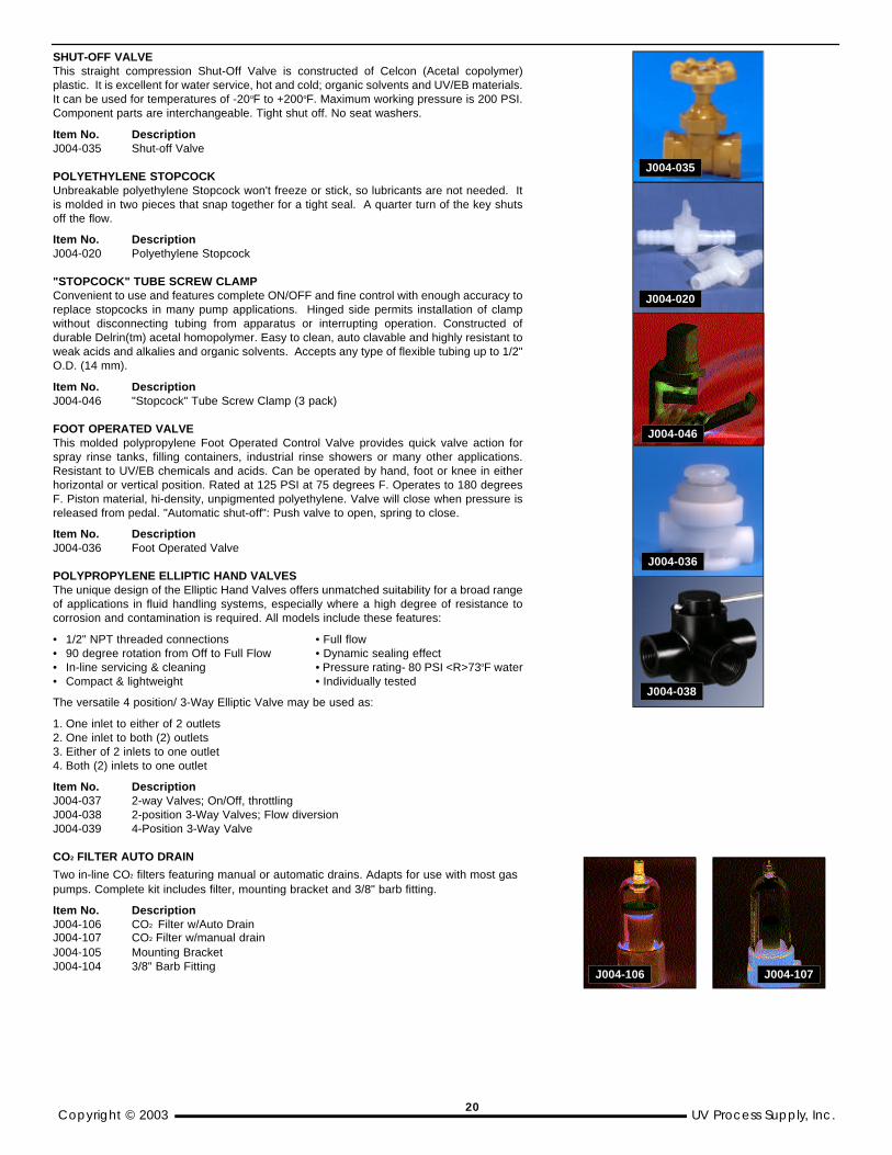
SHUT-OFF VALVE This straight compression Shut-Off Valve is constructed of Celcon (Acetal copolymer)plastic. It is excellent for water service, hot and cold; organic solvents and UV/EB materials.It can be used for temperatures of -20oF to +200oF. Maximum working pressure is 200 PSI.Component parts are interchangeable. Tight shut off. No seat washers.
Item No. Description J004-035 Shut-off Valve
POLYETHYLENE STOPCOCK Unbreakable polyethylene Stopcock won't freeze or stick, so lubricants are not needed. Itis molded in two pieces that snap together for a tight seal. A quarter turn of the key shutsoff the flow.
Item No. Description J004-020 Polyethylene Stopcock
"STOPCOCK" TUBE SCREW CLAMP Convenient to use and features complete ON/OFF and fine control with enough accuracy toreplace stopcocks in many pump applications. Hinged side permits installation of clampwithout disconnecting tubing from apparatus or interrupting operation. Constructed ofdurable Delrin(tm) acetal homopolymer. Easy to clean, auto clavable and highly resistant toweak acids and alkalies and organic solvents. Accepts any type of flexible tubing up to 1/2"O.D. (14 mm).
Item No. Description J004-046 "Stopcock" Tube Screw Clamp (3 pack)
FOOT OPERATED VALVE This molded polypropylene Foot Operated Control Valve provides quick valve action forspray rinse tanks, filling containers, industrial rinse showers or many other applications.Resistant to UV/EB chemicals and acids. Can be operated by hand, foot or knee in eitherhorizontal or vertical position. Rated at 125 PSI at 75 degrees F. Operates to 180 degreesF. Piston material, hi-density, unpigmented polyethylene. Valve will close when pressure isreleased from pedal. "Automatic shut-off": Push valve to open, spring to close.
Item No. Description J004-036 Foot Operated Valve
POLYPROPYLENE ELLIPTIC HAND VALVESThe unique design of the Elliptic Hand Valves offers unmatched suitability for a broad rangeof applications in fluid handling systems, especially where a high degree of resistance tocorrosion and contamination is required. All models include these features:
• 1/2" NPT threaded connections • Full flow• 90 degree rotation from Off to Full Flow • Dynamic sealing effect• In-line servicing & cleaning • Pressure rating- 80 PSI <R>73oF water• Compact & lightweight • Individually tested
The versatile 4 position/ 3-Way Elliptic Valve may be used as:
1. One inlet to either of 2 outlets2. One inlet to both (2) outlets3. Either of 2 inlets to one outlet4. Both (2) inlets to one outlet
Item No. DescriptionJ004-037 2-way Valves; On/Off, throttlingJ004-038 2-position 3-Way Valves; Flow diversionJ004-039 4-Position 3-Way Valve
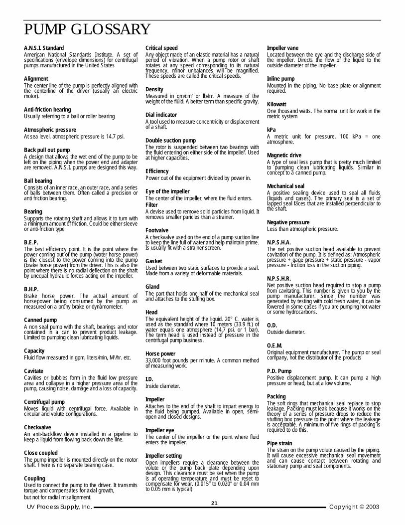
CO2 FILTER AUTO DRAIN
Two in-line CO2 filters featuring manual or automatic drains. Adapts for use with most gas pumps. Complete kit includes filter, mounting bracket and 3/8" barb fitting.
Item No. DescriptionJ004-106 CO2 Filter w/Auto DrainJ004-107 CO2 Filter w/manual drain J004-105 Mounting Bracket J004-104 3/8" Barb Fitting
J004-035
J004-020
J004-046
J004-036
J004-038
J004-107J004-106
20
A.N.S.I. Standard American National Standards Institute. A set ofspecifications (envelope dimensions) for centrifugalpumps manufactured in the United States
Alignment The center line of the pump is perfectly aligned withthe centerline of the driver (usually an electricmotor).
Anti-friction bearing Usually referring to a ball or roller bearing
Atmospheric pressure At sea level, atmospheric pressure is 14.7 psi.
Back pull out pump A design that allows the wet end of the pump to beleft on the piping when the power end and adapterare removed. A.N.S.I. pumps are designed this way.
Ball bearing Consists of an inner race, an outer race, and a seriesof balls between them. Often called a precision oranti friction bearing.
Bearing Supports the rotating shaft and allows it to turn witha minimum amount of friction. Could be either sleeveor anti-friction type
B.E.P. The best efficiency point. It is the point where thepower coming out of the pump (water horse power)is the closest to the power coming into the pump(brake horse power) from the driver. This is also thepoint where there is no radial deflection on the shaftby unequal hydraulic forces acting on the impeller.
B.H.P. Brake horse power. The actual amount ofhorsepower being consumed by the pump asmeasured on a prony brake or dynamometer.
Canned pump A non seal pump with the shaft, bearings and rotorcontained in a can to prevent product leakage.Limited to pumping clean lubricating liquids.
Capacity Fluid flow measured in gpm, liters/min, M3/hr. etc.
CavitateCavities or bubbles form in the fluid low pressurearea and collapse in a higher pressure area of thepump, causing noise, damage and a loss of capacity.
Centrifugal pump Moves liquid with centrifugal force. Available incircular and volute configurations.
Checkvalve An anti-backflow device installed in a pipeline tokeep a liquid from flowing back down the line.
Close coupled The pump impeller is mounted directly on the motorshaft. There is no separate bearing case.
Coupling Used to connect the pump to the driver. It transmitstorque and compensates for axial growth, but not for radial misalignment.
Critical speed Any object made of an elastic material has a naturalperiod of vibration. When a pump rotor or shaftrotates at any speed corresponding to its naturalfrequency, minor unbalances will be magnified.These speeds are called the critical speeds.
Density Measured in gm/cm2 or lb/in2. A measure of theweight of the fluid. A better term than specific gravity.
Dial indicator A tool used to measure concentricity or displacementof a shaft.
Double suction pump The rotor is suspended between two bearings withthe fluid entering on either side of the impeller. Usedat higher capacities.
Efficiency Power out of the equipment divided by power in.
Eye of the impeller The center of the impeller, where the fluid enters. Filter A devise used to remove solid particles from liquid. Itremoves smaller paricles than a strainer.
Footvalve A checkvalve used on the end of a pump suction lineto keep the line full of water and help maintain prime.Is usually fit with a strainer screen.
GasketUsed between two static surfaces to provide a seal.Made from a variety of deformable materials.
Gland The part that holds one half of the mechanical sealand attaches to the stuffing box.
Head The equivalent height of the liquid. 20° C. water isused as the standard where 10 meters (33.9 ft.) ofwater equals one atmosphere (14.7 psi. or 1 bar).The term head is used instead of pressure in thecentrifugal pump business.
Horse power33,000 foot pounds per minute. A common methodof measuring work.
I.D.Inside diameter.
Impeller Attaches to the end of the shaft to impart energy tothe fluid being pumped. Available in open, semi-open and closed designs.
Impeller eye The center of the impeller or the point where fluidenters the impeller.
Impeller settingOpen impellers require a clearance between thevolute or the pump back plate depending upondesign. This clearance must be set when the pumpis at operating temperature and must be reset tocompensate for wear. (0.015” to 0.020” or 0.04 mmto 0.05 mm is typical)
Impeller vane Located between the eye and the discharge side ofthe impeller. Directs the flow of the liquid to theoutside diameter of the impeller.
Inline pump Mounted in the piping. No base plate or alignmentrequired.
Kilowatt One thousand watts. The normal unit for work in themetric system
kPaA metric unit for pressure. 100 kPa = oneatmosphere.
Magnetic drive A type of seal less pump that is pretty much limitedto pumping clean lubricating liquids. Similar inconcept to a canned pump.
Mechanical seal A positive sealing device used to seal all fluids(liquids and gases). The primary seal is a set oflapped seal faces that are installed perpendicular tothe shaft.
Negative pressure Less than atmospheric pressure.
N.P.S.H.A. The net positive suction head available to preventcavitation of the pump. It is defined as: Atmosphericpressure + gage pressure + static pressure - vaporpressure - friction loss in the suction piping.
N.P.S.H.R.Net positive suction head required to stop a pumpfrom cavitating. This number is given to you by thepump manufacturer. Since the number wasgenerated by testing with cold fresh water, it can belowered in some cases if you are pumping hot wateror some hydrocarbons.
O.D. Outside diameter.
O.E.M. Original equipment manufacturer. The pump or sealcompany, not the distributor of the products
P.D. Pump Positive displacement pump. It can pump a highpressure or head, but at a low volume.
PackingThe soft rings that mechanical seal replace to stopleakage. Packing must leak because it works on thetheory of a series of pressure drops to reduce thestuffing box pressure to the point where the leakageis acceptable. A minimum of five rings of packing isrequired to do this.
Pipe strain The strain on the pump volute caused by the piping.It will cause excessive mechanical seal movementand can cause contact between rotating andstationary pump and seal components.
PUMP GLOSSARY
UV Process Supply, Inc. Copyright © 200321

Positive displacement pump Called a PD pump. Gear, sliding vane, progressivecavity, lobe etc. the capacity determined by the pumpspeed. The maximum head is determined by thehorsepower available and the casing strength.
Pressure head The pump head exerted by atmospheric pressure orany additional pressure that might be in the vessel.
Pump curve A diagram supplied by the pump manufacture todescribe the relationship between the head and thecapacity of a particular pump using various sizeimpellers. The curve also includes information aboutefficiency, horse power consumption, N.P.S.H.required, etc.
Run out Twice the distance that the center of the shaft isdisplaced from the axis of rotation.
Shaft packing The soft packing supplied by pump manufacturers.Most of these leaking packings are being replacedby mechanical seals.
Shut off head The maximum head that the pump can generate witha given impeller outside diameter and horsepowerdriver.
Sleeve bearing A non precision bearing. Usually manufactured fromcarbon, Teflon. brass etc., Allows too much axial andradial movement for most mechanical sealapplications.
Specific Gravity A measure of the weight of a liquid. Fresh water at4°C (39°F) is given a value of one. If the liquid youare questioning will float on water the specific gravityis less than one. If it sinks, it is higher than one.Density is a better term.
Specific speed A formula that describes the shape of a pumpimpeller. The higher the specific speed the lessN.P.S.H. required.
Suction head The head on the suction side of the pump. Yousubtract it from the discharge head to determine thehead being produced by the pump. It is a sum of thestatic, pressure and friction heads.
System head The head caused by friction in the piping. valves andfittings.
T.D.H. Total discharge head. A combination of the suctionhead and the head being produced by the pump.
Total head The amount of head produced by the pump.Discharge head minus suction head. If suction headis a negative number it is added to the dischargehead.
Velocity A measurement of the speed of the liquid in thesystem. Measured in feet or meters per second. Thepump is a constant velocity device.
Volute casing Derives is name from a spiral shaped casingsurrounding the pump impeller. It converts velocityenergy to pressure energy.
Vortex Pump A type of pump used for excessive solids. Theimpeller is recessed into the volute. A very lowefficiency design, but practical in many applications.
Water Horse Power (W.H.P.) The calculated horse power coming out of the pumpusing the formula WHP = head x gpm/3960
WattA measure of power. 746 watts equals onehorsepower.
Wet endThe part of the pump that gets wet from the pumpingfluid. Includes the volute, stuffing box, impeller wearrings, and shaft or sleeve.
PUMP GLOSSARY
Copyright © 2003 UV Process Supply, Inc. 22
UV Process Supply, Inc. Copyright © 2003
PRODUCT ORDER FORM1229 W. Cortland Street. Chicago, IL 60614
Voice: 1-800-621-1296; 1-773-248-0099Fax: 1-800-UVLAMPS; 1-773-880-6647
Internet: www.uvprocess. come-mail: [email protected]
Copyright © 1999 by UV PROCESS SUPPLY®, INC. All rights reserved. Reproduction in whole or in part without written permission of the copyright owner is prohibited.
• Ordering Assitance •• Ordering Assitance •Customer Service Department
Toll-free Voice: 1-800-621-1296 Voice: 1-773-248-0099
• Technical Questions •• Technical Questions •Visit our web site at www.uvprocess.com
for complete technical and pricinginformation,
UV FAXTS®...Service to receive productinformation through your fax machine, orcall our Customer Service Department.
ALL SALES ARE SUBJECT TO THE TERMS,CONDITIONS, AND WARRANTY FOUND WITH
THE “GENERAL INFORMATION” SECTIONOF THIS CATALOG.
SHIP TO:SHIP TO:Name: _____________________________________________
Company: _____________________________________________
Address: _____________________________________________
City: _____________________ State/Province: ________________
Zip/Postal: ______________ +4: ________ Country: _________
Phone: _____________________ Fax: _______________ E-mail:______
BILL TOBILL TO: Same as Above
Acct. Payable Contact: ________________________________________
Company: _____________________________________________
Address: _____________________________________________
City: _____________________ State/Province: ________________
Zip/Postal: ______________ +4: ________ Country: _________
Phone: _____________________ Fax: _______________ E-mail:______
• Open Account Ordering: Please provide your company purchase order number: _____________________
• New Account Ordering: Please review the “General Information” section for additional instruction.
ITEM NO. QUANTITY SIZE ITEM NO. QUANTITY SIZE DESCRIPTION PRICE/EA TOTAL DESCRIPTION PRICE/EA TOTAL
Fax orders by dialing toll-free 1-800-99UVLAMPS (1-800-993-2988)
or by dialing 1-773-880-6647Make copies of this form for future use, or call the UV FAXTS®...Service at 773-880-6649 and enter UV FAXTS®...Code “ORDER” (67337) to automatically receive additional order forms through your fax machine.
Total Merchandise Value
Standard Shipping & Handling(see page A for details)
Subtotal
ILLINOIS Deliveries add 8.75%sales tax to Subtotal
TOTAL
SAFETY • INK & COATING HANDLING • MAINTENANCE & SHOP • CURING CONTROLS • CURING EQUIPMENT • PRINTING SUPPLIES
23