Embed Size (px)
Citation preview

An introduction to steam generation and distribution
Steam Handbook
Products Solutions Services


1
Dr. Ian Roberts
Phillip Stoor
Michael Carr
Dr. Rainer Höcker
Oliver Seifert
An introduction to steam generation and distribution
Steam Handbook

Endress+Hauser – Steam Handbook 2
Impressum
Publisher Endress+Hauser Flowtec AG, CH-4153 Reinach/BL
Editor in chief Thomas Stauss
Editorial team Michael Carr, Dr. Rainer Höcker, Dr. Ian Roberts, Romeo Rocchetti, Oliver Seifert, Thomas Stauss, Phillip Stoor
Illustrations Kodotec (Lörrach, Germany)
Layout, set Beatrice Meyer
Steam Handbook, 1st Edition 2017
© Copyright 2017 by: Endress+Hauser Flowtec AG, CH-4153 Reinach/BL
All rights reserved. This work is copyright protected in its entirety.All use in breach of copyright laws without the express permission of the publisher is forbidden. Duplication, translation, microfilming, storage and processing in any form of electronic media is prohibited.

3
Contents
5 Foreword5 What this document is about?
5 Who this document is for?
5 How to use the document?
7 A short history of boiler designs
11 Why use steam?11 What is steam used for?
12 Where is steam used?
13 A generic steam system
17 Types of industrial steam boilers17 Coil steam generator (once through boiler)
19 Water-tube boiler
21 MTHSboilers(fire-tubeor smoke-tube boilers)
24 Basic overview of boiler controls with reference to EN 12953
25 Water treatment
28 Level controls
29 Feedwater pump arrangements
30 Burners
33 Basic steam distribution
37 How steam moves (simple explanation)
41 On the motion of steam (detailed explanation)
55 Some hazards of steam55 Boiling liquid expanding vapor explosion (BLEVE)
56 Column collapse water hammer
59 Sub-cooled condensate induced water hammer
61 Flash steam explosion
61 Overpressure in the distribution system
61 Overpressure (inside a pressure vessel)
62 Plugflowwaterhammer
63 Steam hammer
63 Temperature
64 Vacuum draw
65 Waterlogging
67 Boiler operation67 The boiler operator
68 The manager
69 The role of technology in the modern boiler house
73 Steamboilerefficiency
Endress+Hauser – Steam Handbook 4
73 Indirect method
80 Direct or fuel-to-steam efficiency
87 Boiler management and control87 Typical instrumentation for boiler management
90 Contamination of condensate
90 Boiler level controls
90 Hotwell temperature
91 Hotwell level
91 Total dissolved solids (TDS)
93 The European boiler market94 Regulatory structure
95 Market structure
101 Appendix101 Nomenclature
104 Dimensionless numbers
105 List of abbreviations
106 Glossary
115 Bibliography
117 Index
5
Foreword
What this document is about?This document is designed to give a comprehensive technical overview into what steam is in all its forms, how to measure it, where and why it is used for in industrial processes, and to give an insight into unexpected and potentially hazardous situa-tionsthatmayarisefromtheprocessconfigurationandconditions.Itusesclearandrelativelyeasytofollowexamples,withtheminimumofmathematics.However,itdoes assume a level of interest and curiosity in steam production, distribution and its use, that will be rewarded by taking on-board the principles and practice given inthedocument.
Who this document is for?This document is for personnel involved in all aspects of medium sized boiler plant, steam distribution and saturated steam used for both general services and direct process purposes in all industries:
1. Processengineers2. Energymanagers3. Procurementstaff4. Technicalmanagers5. Operationsmanagers6. InstrumentationSales&Marketingstaff7. Maintenanceandapplication/Supportengineers8. Controlandinstrumentengineers(includingDCS)
How to use the document?For readers who just wish to gain a general understanding, there are sections that canbesafelypassedoverwhichareincludedspecificallyforengineerswithatechni-calinterestinunderstandingthethermodynamicsofsaturatedsteam.
This document is not intended to be an engineering design guide, nor is it a commer-cialguidetoaspecificmanufacturer’sequipment.Itisintendedasbothadescrip-tion of what is objective current best practice – so that readers can make informed equipmentdesign,purchasingandmaintenancedecisions–andtodiagnose/solveproblemsinexistingsteamsystems.

Endress+Hauser – Steam Handbook 6

7
A short history of boiler designsShell and tube-saturated steam boilers of the current packaged form have been manufactured since before the second world war, and their lineage may be traced directly back to the Cornish boilers of the early nineteenth century, invented by the British inventor and mining engineer Richard Trevithick(1771–1833).
Early steam boilers such as the wagon, the haystack and the egg-ended boiler workedatlowpressures(lessthan0.7barg)andwereusedtodrivepumpsatmines,particularlythedeepminesofCornwallandtheNorthEastviawithNewcomen’satmospheric andWatt’s condensing engines. These boilerswere very inefficient:Murray(1959)reportedBrownlieasestimatingtheefficiencyofegg-endedboilersat34%.AscoalwasimportedtoCornwallbyseaandarrivedatthetinminesbypackhorse, itwasaconsiderableexpense to themineowners.Trevithickrealizedthat if he utilized the power developed from high pressure steam or strong steam as itwasthenknown,theefficiencywouldbeimproved.
Ashorthistoryofboilerdesigns
Figure 1: Richard Trevithick (1771–1833). British inventor and mining engineer. Trevithick was the first to successfully use high-pressure steam (then known as “strong” steam). Until ca. 1800, the weakness of existing boilers coupled with the influence of James Watt had generally restricted steam boilers to very low pressures or “weak” steam. Right: Trevithick's “Puffing Devil” – the first steam-powered locomobile drove on streets, not on tracks.
Endress+Hauser – Steam Handbook 8
OneofTrevithick’sboilers,thatmanufacturedbyHazeldinesaround1806andcur-rentlyondisplayattheScienceMuseuminLondon, istypicalofhisdesigns. It iseasilyrecognizableastheforerunnertotoday’spackagedboilerswiththefurnaceand a single large diameter convective pass mounted inside a cylindrical iron pres-surevessel.Trevithick’sboilersof this type typicallyoperatedatpressures in therangebetween1.4and3.5barg.Whilstefficiencydataaredifficulttofindfortheseearlyhighpressureboilers,thattheyweresignificantlymoreefficientisknown.Rolt(1960,p.168)illustratesthisbystatingthatDolcoathmine’scoalbillreducedfrom£1000to£612perannumfollowingtheinstallationofoneofTrevithick’sboilersinaround1810.
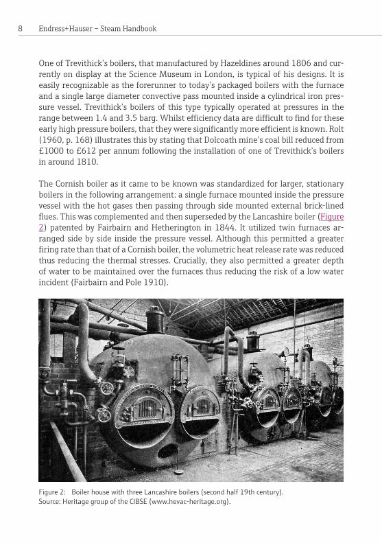
The Cornish boiler as it came to be known was standardized for larger, stationary boilers in the following arrangement: a single furnace mounted inside the pressure vessel with the hot gases then passing through side mounted external brick-lined flues.ThiswascomplementedandthensupersededbytheLancashire boiler (Figure 2) patentedbyFairbairnandHetherington in1844. It utilized twin furnacesar-rangedsidebyside inside thepressurevessel.Although thispermittedagreaterfiringratethanthatofaCornishboiler,thevolumetricheatreleaseratewasreducedthusreducingthethermalstresses.Crucially,theyalsopermittedagreaterdepthof water to be maintained over the furnaces thus reducing the risk of a low water incident(FairbairnandPole1910).
Figure 2: Boiler house with three Lancashire boilers (second half 19th century). Source: Heritage group of the CIBSE (www.hevac-heritage.org).
9
In 1858 the Manchester Steam Users Association for the Prevention of Steam Boiler Explosions was formed to inspect operational boilers, investigate the causes of ex-plosionsandpromotefueleconomy.Asignalfeatureoftheassociationwasthatitintroduced the concept of insurance to the industry: In the event of the explosion of an approved boiler – for whatever reason – £300 would be paid to its owner (Fair-bairnandPole1910,pp.258–268).Whilsttheassociationwasformedinparttoavoidgovernment interference intheaffairsofsteam-engineproprietors, itsoonbecame apparent that legislation of some form was required in order to force own-erstomaintainandoperatetheirboilersinaccordancewithbestpractice.
That some form of legislation was required was evident as catastrophic boiler fail-ure and consequent loss of life and production was an everyday feature of steam generationatthistime.HughMasonM.P.(1882,pp.1348–1355),duringthesec-ond reading of the Boiler Explosions Bill 1882 reported that “one boiler explosion occurred every week, and one person was killed, and two injured, more or less, by a boiler explosion every four days.”
The success of the Manchester Steam Users Association prompted the formation of othersimilarsocietiesandinsurancecompanies.WhenParliamenteventuallyintro-duced regulations concerning steam boilers, this system of inspection and insurance wasadoptedandbecamemandatory.
Simultaneously, various learned societies such as the American Society of Mechani-cal Engineers (ASME)wereinvestigatingthefundamentalscientificandengineer-ingprinciplesthatunderlietheuseandapplicationofsteam.Thatthesewerenotfullyunderstood,orwereplainlywrong,ismanifest.Forexample,Fischer(1874,pp. 311–323), in an address to the Hannover section of the Society of German Engineers in 1874, discussed inter alia the hypothesis that water decomposed into itsconstituentelementsinsidetheboilershellthusforminganexplosivemixture.The work of these societies led to the introduction of standards for the design and construction of boilers and pressure vessels the ASME Boiler and Pressure Vessel Codebeingtheoldest–originallypublishedin1914–andpossiblybestknown.
By the end of the nineteenth century, the Lancashire and Economic (acoalfiredshellandtubeunit)boilerswerethedominanttypesforsaturatedsteam.Thepack-aged boiler concept was imported to the United Kingdom from the United States of AmericaaftertheSecondWorldWarfollowingavisittothatcountrybyateamofexpertssponsoredbythethenMinistryofFuelandPower(Goodall1980).Afurthersignificantdevelopmentresultingfromthisvisitwastheadoptionofoil(replacingcoal) from the 1950s onward and supplemented, in turn, by natural gas from the
Ashorthistoryofboilerdesigns

Endress+Hauser – Steam Handbook 10
1960s.Thisdevelopment,intheUnitedKingdom,wasdrivenbytheClean Air Act of1956whicheffectivelyproscribedtheuseofcoalincities.
Thepackagedboilerprovidedtheuserwithanumberofbenefits, i.e.boilersthatweresmaller,cheaperandmoreefficientthantheLancashireandEconomicunitswhich they replaced. Theywere also suppliedwith all necessary accoutrements, requiring only the connection of services for them to commence operation, substan-tiallyreducingboththetimeandthecostofinstallation.

11
Why use steam?The thermophysical properties of steam change as its conditions of state change and itisrelativelyeasytogeneratesteamacrossawiderangeofstates.Consequentlysteam has a very wide range of applications.Thefollowingbrieflydescribesafewofthemajorthermophysicalattractionsofsteamtotheengineer.Anexplanationofthe various terms used can be found in the glossary located towards the end of this publication.
• It has a very high heat content, of which a large proportion is contained in the latentheat(enthalpyofchangeofphase).
• Theheatcontentofthelatentheatcanbegivenupandreleasedveryquickly.• Large amounts of steam can be driven through a process very quickly which,
combined with the previous point, allows very large amounts of heat to be transferred to the process in a very short time using relatively small heat exchangers.
• The heat content of the enthalpy of change of phase (saturated and wet steam) may be given up in conditions which approximate very closely to constant temperatureallowingcloseprocesscontrolandprocesshomogeneity.
•Very high steam pressures and temperatures can be achieved which is advantageousforprocessessuchaspowergeneration.
• Steamcanbereadilydistributedandeasilycontrolled.• Heatmaybeextractedinacascadeofprocesses.• Steam is water and water is required to be added to many foods during their processing.
• Steamisneithertoxicnorafirehazard.• Inmanylocations,waterischeap,readilyavailableandeasilypurified.• In many indirect processes the condensate can be reused in its entirety recoveringboththehighpuritywateranditshighresidualheatcontent.
• Steam has a wide range of thermophysical properties, the optimum being selectedforagivenprocess.
What is steam used for?We can reduce the answer to this question to three main categories:
• Power generation: The steam used for power generation is usually superheated steamasthehigherthetemperature,thehigherthethermodynamicefficiencythatcanbeachieved.
• Process: This is predominately saturated steam as it is the latent heat and sometimesthewateraswellthatisrequired.Moreoverthelatentheatisgivenupmuchmorequicklybysaturated/wetsteamthansuperheatedsteam.
Why use steam?

Endress+Hauser – Steam Handbook 12
–Indirectprocessesusejustthelatentheatofthesteam. – Directinjectionprocessesconsumeboththeheatandthewater.
• Space heating: This almost invariably uses saturated steam as the heat transfer rates from saturated steam to the heat exchangers are very much higher than if thesteamweresuperheated.
Where is steam used?Althoughtherangeofapplicationsforsteamhasreducede.g.replacementofsteamtrains,itisstillfoundinawiderangeofapplicationsofwhichjustafewarebrieflydescribed below:
•Nuclear power stations: The nuclear part of these power stations is just a meansofgeneratinglargeamountsofheat.Thisheatistransferredtowater togeneratesuperheatedsteamwhichdrivesaturbinetogenerateelectricity. In fossil fuel power plants, this heat is generated by burning the fossil fuel (e.g.coal).
•De-commissioning nuclear power stations: In the United Kingdom, steam is used to keep the pile caps of de-commissioned Magnox stations at a known temperature.(Apilecapcanbethoughtofinverysimplisticterms,asthelidofthevesselcontainingthenuclearfuel).
• Food processing: Steam at common pressures (6 to 10 barg) is at temperatures in the range 150 to 180 °C which is ideal for cooking and the steam is very controllable.Anexampleisevaporatingmilk:steamejectorsareusedtoevaporateoffsomeofthewaterfractionofthemilkbycreatingapartialvacuuminthevesselholdingthemilkthusreducingitssaturationtemperature.
•Drinks manufacture e.g. whisky: In a pot still, used for the manufacture of malt whisky, the distillation process is frequently undertaken using steam in coils as theheatsource.Thisformofdistillationisabatchprocessandthecondensateisrecoveredforre-use.Inacontinuousdistillationprocesse.g.inaPatentorCoffreystillthesteamisdirectlyinjectedintothestillandthesteamcannotberecovered.
• Laundries: Steam is used for heating ironer beds and heating wash water by directlyinjectionintocontinuousbatchwashers.Itisalsousedforconditioninggarmentspriortofolding.
• Sterilization: Within hospitals for medical purposes and also for sterilization of anywastewhichisdeemedtorequireit.Again,thedesiredtemperaturescaneasilybeachievedandmaintainedinaverycontrollablemanner.
• Trace heating: Some fuels such as heavy fuel oil require heating in order to reduce theviscosityofthefuelsothattheycanbepumped.Thesameistrueforsome chemical storage tanks, whereas others require warming for frost protectionandotherreasons.

13
A generic steam systemFigure 3 showsageneric steamsystem.Forgood reasonwater is sometimes re-ferred to the “universal solvent” and as such contains a variety of substances a num-berofwhichareundesirabletosomegreaterorlesserdegree.Themake-up water totheboilerthereforeneedstobeconditioned.Itisveryimportanttonotethatthecomposition of the make-up water is dependent upon the location and that dif-ferentlocalitiesandwatersourceswillrequiredifferenttreatmentregimes.Asanexamplewaterdrawnfromasourcesuchasariverwillrequirefiltrationtoremovesolidparticulateswhereaswaterdrawnfromamunicipalmainwillnot.Theprimarywater treatment system indicated in Figure 3 will have a variety of functions, includ-
Condensate trapson steam lines
Indirectfactory process
Direct injectionfactory process
Unwanted lossese.g. leaks
Optionalflash vessel
Economizer
Pump
Chemicaldosing
Primary watertreatment system
Liquid to drain
Line equipment e.g. control valvesand pressure reducing sets
Manual samplepoint
Flashsteam
Bottomblowdown
TDSblowdown
Steamto process
Make-upwater
Steaminjection
Condensate monitoringand bypass valve
Condensate dump linefor total loss systems
Processtraps
To d
rain
Cond
ensa
te re
turn
Hotwell/deaerator
Steamboiler
LOST
Blowdownvessel
Flash steam
Agenericsteamsystem
Figure 3: Scheme of a generic steam system.

Endress+Hauser – Steam Handbook 14
ingfiltration.Themostimportantofthesehoweveristheremovalofscaleformingcompounds or their conversion into to substances which do not precipitate out to formhardscaleusingoneofanumberoftechniquessuchasbaseexchangesoften-ingorreverseosmosis.Thistreatedwateristhenconditionedthermallybywhichitstemperatureisincreasedeitherusingcondensatereturnorprimesteaminjection.This is done to partially remove dissolved oxygen (in an atmospheric hotwell) or to render it a practicable minimum (by use of a deaerator).Theincreaseintempera-turealsoservestoreducethethermalshocktotheboilerwhichisasignificantcauseoflocalizedcrackingofthepressurevessel.Thewateristhentreatedwithvariouschemicals to give it the optimum properties, such as correct pH or required level of oxygenscavenger.
Once conditioned, the feedwater is pumped into the boiler. The function of theboiler is to generate steam by adding heat to the water whilst constraining it both physicallyandthermally.Thepressure inside the boiler is controlled and also lim-itedtoapermittedmaximum.Thewater level is also controlled to ensure that the heatedsurfacesarealwayssubmerged.Ifthelevelfallsbelowapredeterminedsetpoint, limiters are employed to shut the boilerdown.Thewaterqualityinsidetheboiler is also monitored and controlled in a variety of ways to ensure that its quality ismaintained. The steam which leaves a boiler contains a very small amount of impurities – much lessthanthefeedwater.Thismeansthatsolids,bothdissolvedandsuspendedcon-centrateinsidetheboilerandthesemustbecontrolledandremovedrespectively.Dissolved solids are considered in terms of “Total Dissolved Solids” (TDS) for which thereisapermittedmaximumwhichdependsuponthetypeofboilerbeingused.These are controlled by measuring the amount of TDS in the boiler and then blow-ing down some of the liquid water in the boiler to remove some of the solids and so reduce theTDS.Onmodernboilers this isnormallyaccomplishedbyusinganautomatedsystemalthoughitmaystillbeperformedmanually.Suspendedsolidssinktothebottomoftheboilertoformasludge.Thesesolidsareremovedusingbottomblowdown.Thisconsistsofavalvelocatedatthebottomoftheboilerwhichisquicklyopenedonceadayforapproximatelytenseconds.Thissuddendischargeremoves the sludge from the bottom of the boiler preventing over-heating of the lowerpartofthefurnace.BothTDSandbottomblowdownarenormallydischargedto a blowdown vessel which safely dissipated its pressure and heat prior to discharge todrain.However, if thequantityofblowdownwater is largeenough, itmaybepassedthroughaflashvesseltorecoversomeofthewateranditsheatcontent.
Prime steam leaves the boiler and enters the distribution system by virtue of the pressuredifferencebetweentheboilerandthevariouspointsofuse.Someofthis

15
steam may be used to heat the hotwell or deaerator, the majority however goes to process.As thesteamtravels throughthedistributionsystem itusesupsomeofits own energy in doing so, condensing back into the liquid phase and is termed condensate.
Condensateisalsoformedduetoheat lossestoatmosphere.Asaruleofthumb, anuninsulatedpipewillloseatleasttentimesmoreheatthananinsulatedpipe.Condensate is almost without exception, unwanted, and is removed using traps, normally for return to the boiler house where the high-quality water and its residual heatcontentarerecovered.
Asthesteamapproaches,theconsumersitspressureisconditionedusingpressure reducing valves (PRV) to provide a consistent and controlled pressure onto the pro-cess.Steamconsumersfallintotwomaincategories:direct and indirectprocesses.Direct processes consume the steam itself utilising both the water and heat content, sonothingisreturnedtotheboiler-house.Indirectprocessesutilizejustthelatentheat content of the steam so that it condenses back to the liquid phase and is nor-mally returned to the boiler house for re-use; although in a few specialized processes thecondensateisdiscardedasamatterofcourse.Incertainprocessesthereisariskthat the condensate becomes contaminated from which dangerous incidents may result.Itisthereforeveryimportanttoassesstherisksassociatedwiththepotentialfor contamination of condensate and take appropriate steps such as the inclusion of monitoring systems for condensate and the selection of the most appropriate level controls.
Correctwatertreatmentisvitaltothesafe,effectiveandefficientoperationofanysteamraisingplant.Incorrecttreatment,failuresofequipmentandpooroperationhave resulted in many boiler explosions, accidents and dangerous occurrences over theyears.
Agenericsteamsystem

Endress+Hauser – Steam Handbook 16

17
Types of industrial steam boilersThereareanumberofdifferenttypesofsteamboilers.Thetypepreferredforagiveninstallation will depend in the main on the type of steam, steam pressure and output required.Whilstthereissomeoverlapinthecapabilitiesofthedifferenttypes,itismoreusualforagenerictypeofboilerto“selectitself”,e.g.multi-tubularhorizontalsteam boilers (MTHS) in breweries or water-tube boilers for power stations – the purchaser then being restricted to a choice of units from competing manufacturers whomayofferdifferentsub-classeswithinthegeneric type.Thefollowingpagesgive a brief overview of the existing main boiler types:
• Coil steam generator (once through boiler)•Water-tube boilers • MTHSboilers(fire-tubesmoke-tubeorshellboilers)
Coil steam generator (once through boiler)Coil steam generators operate with the water contained inside a continuous tube coil (Figure 4).Aswater is pumped through the coil it is heated by an externalflame,andonceenoughheathasbeentransferred,thewaterboilsinsidethetubetogeneratesteam.Themajorityofunitsaresuppliedtotheprocessindustryoperatingatrelativelylowpressures(<10barg)andlowcapacities(<1.5MW)althoughitispossibletogeneratesteamatmuchhigherpressures(>100barg).
Types of industrial steam boilers
Figure 4: Once-through steam generator (Courtesy: AB&CO – TT BOILERS LTD, Denmark).
Endress+Hauser – Steam Handbook 18
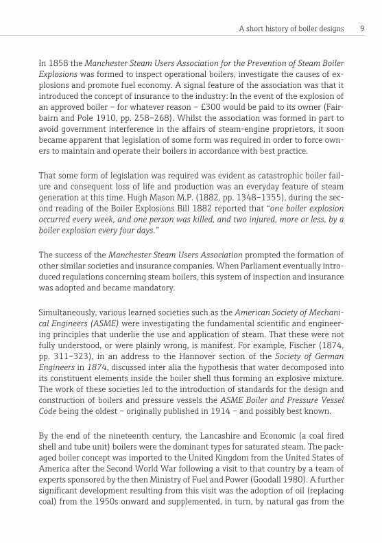
The main advantage of a coil steam generator is its ability to produce steam at short noticeastheydonotcontainalargevolumeofwater.Furthermorethissmallwa-ter capacity means that they do not have the explosive capabilities associated with MTHS boilers – although there is, as with all boiler types, the potential for an un-wanted,potentiallydangerousreleaseofsteam.Theinstallationandregulatoryen-vironmentforthesegeneratorsaregenerallylessonerousthanforMTHSboilers.Theyarecompactunitsandareoftenfoundtobeverycosteffectivewheresteamdemand is infrequent.Against this the steam quality can be low suffering from
Smokestack
Water pipes
Furnace
Steam
Flue gases
Water
Figure 5: Principle of a water-tube boiler.
19Types of industrial steam boilers
problemswithwetnessandpressurevariationasitisdifficulttopreciselymatchtheburneroutputtothesteamloadespeciallywhenthedemandfluctuatessuddenlyoratsustainedhighdemandrelativetotheratedcapacityofthegenerator.Theyarevery sensitive to scale build-up due to poor water treatment and require a relatively highstandardofoperator trainingforbestperformance.Start-up lossesarehighand steam generators tend to be less economic in situations where high demand is intermittentbutfrequent.
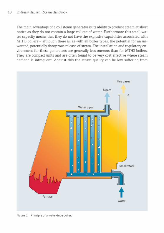
Water-tube boilerThe water-tube boiler was patented by Babcock and Wilcox in 1867. Figure 5 and Figure 6 show the basic principle of operation: The water is injected into a drum knownasthewaterormuddrumandthenflowsthroughthetubesandintothesteamdrumlocatedatahigherlevelboilingtoformsteam.Veryhighoutputsandpressures
Figure 6: A Babcock and Wilcox water-tube boiler. From: Ripper, William C.H. (1923). Heat Engines, London, p. 207. 1 = Drum (for water and steam), 2 = Safety valve, 3 = Main stop valve, 4 = Water tubes, 5 = Superheater tubes, 6 = Baffle plates, 7 = Fire door, 8 = Feed valve, 9 = Water level indicator, 10 = Pressure gauge
1
23
4
6
6
7
8
9
10
5
Endress+Hauser – Steam Handbook 20
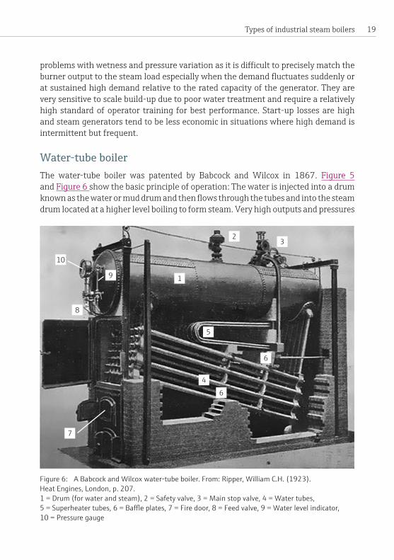
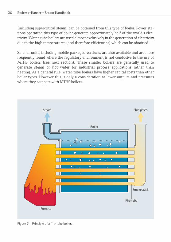
Smokestack
Steam Flue gases
Boiler
Furnace
Fire tube
(including supercriticalsteam)canbeobtainedfromthistypeofboiler.Powersta-tionsoperatingthistypeofboilergenerateapproximatelyhalfoftheworld’selec-tricity.Water-tubeboilersareusedalmostexclusivelyinthegenerationofelectricityduetothehightemperatures(andthereforeefficiencies)whichcanbeobtained.
Smaller units, including mobile packaged versions, are also available and are more frequently found where the regulatory environment is not conducive to the use of MTHS boilers (see next section). These smaller boilers are generally used togenerate steam or hot water for industrial process applications rather than heating.Asageneralrule,water-tubeboilershavehighercapitalcoststhanotherboiler types.However this isonlyaconsiderationat loweroutputsandpressureswheretheycompetewithMTHSboilers.
Figure 7: Principle of a fire-tube boiler.

21Types of industrial steam boilers
MTHSboilers(fire-tube or smoke-tube boilers)The modern MTHS boiler (Horizontal Multi-tube Steam Boiler, Figure 7) can trace itslineagedirectlybacktoTrevithick’sCornish boiler of the early nineteenth century via the Cornish, Lancashire, Scotch Marine and Economic boilers before arriving at themodernpackagedboilerwhichwasfirstintroducedinthetwentiethcenturyintheUnitedStatesofAmerica.Asthenamesuggests,productsofcombustionratherthanwaterorsteamflowinsidethetubes.
ThereareamultiplicityofMTHSboilerdesigns,andtheefficiencyofaboilerisde-termined by the arrangement and sizing of the convective heat transfer tube passes, on the general principle that the greater the convective heat transfer surface area thegreatertheefficiency,albeitatgreatercostandcomplexity.Twocommonde-signs, the three-pass wetback (Figure 9)andthereverseflameMTHSboilers(Figure 10)willbeconsideredinmoredetailbelow.Figure 8 shows a modern three-pass wetbackMTHScombinationboiler.
Figure 8: Byworth Yorkshireman series combination steam boiler (Courtesy of Byworth Boilers).
Endress+Hauser – Steam Handbook 22
MTHS boilers are commonly found working at pressures between 6 and 18 barg although units rated at up to 32 barg are available from a limited number of manu-facturers.MTHSboilerssupplysaturatedsteam.Infrequentlysomesuperheatcanbe generated with the inclusion of an external super-heater,oftenmountedinthefrontsmokeboxorthefurnacereversalchamber.
MTHS boilers are often compared using a rating known as from and at 100 °C, e.g.a1000kg/hrF&A100 °C.This isnotameasureofsteamoutputbutrather of theevaporative capacityof theboiler.This isequivalent tonetenergy releasecapability of the boiler: 1 kg/hr being equivalent to a net heat release rate of 2257kJ/hr(627W).Thismeasureoriginatedinthenineteenthcenturyandisstillusedtocompareboilerratingstoday.
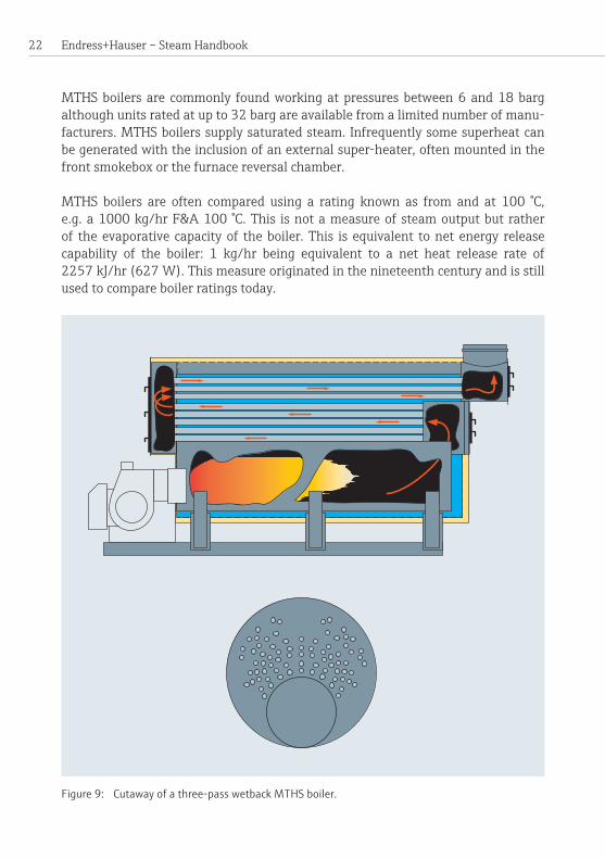
Figure 9: Cutaway of a three-pass wetback MTHS boiler.
23Types of industrial steam boilers
Flue gasesSteamoutput
Steam spaceWater
Thimble furnace
Tubes around furnace
Burner
Water
Furnaceback wall
Three-pass wetback MTHS boiler general arrangementThis type of boiler utilizes a cylindrical pressure vessel which serves to constrain the water, both physically and thermally (Figure 9).Allofthedirectlyheatedsurfacesare contained within this pressure vessel and, crucially, must be submerged at all timeswhentheboilerisoperatinginordertopreventthemfromoverheating.Theuppermost portion inside the pressure vessel contains steam and is known as the steamspace.
Combustion takes place inside the furnace which can be a plain cylinder in very smallboilers.Thefurnaceinlargerboilershowever,needstobeabletoaccommo-date thermal expansion and in order to do so is either fully or partially corrugated or containsanumberofexpansionjointsknownasbowlinghoops.Combustionshouldbe completed inside the furnace and approximately 50% of heat transfer takes place there.Followingonfromthefurnacearetwobanksofconvectivetubeswhichex-tractaround30%additionalheat.Thesearenamedconvectivepassesasthepre-dominantformofheattransferisconvective.Inordertominimizethesizeoftheboiler,thetubesarearrangedinbanks,thegasflowbeingreversedattheendofthefurnaceandeachtubebank.
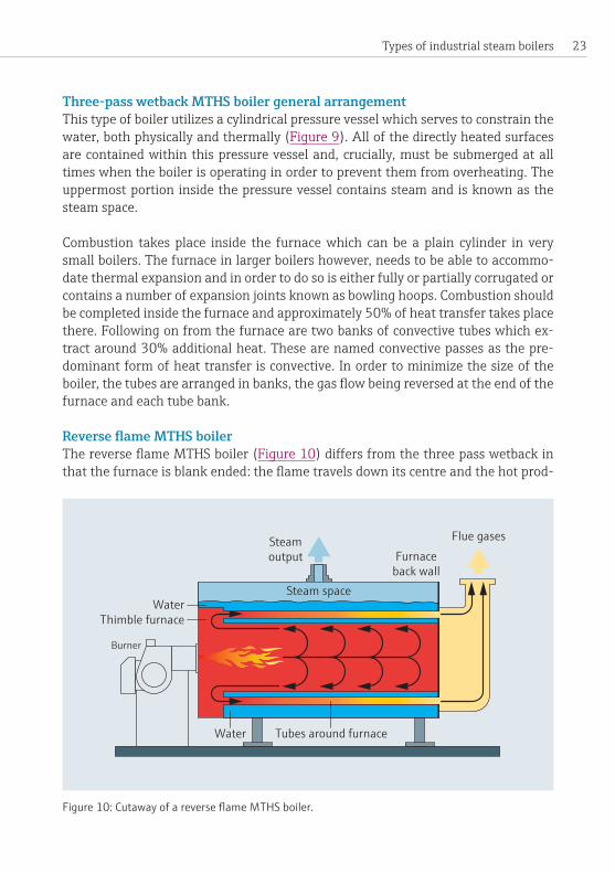
ReverseflameMTHS boilerThereverseflameMTHSboiler(Figure 10)differsfromthethreepasswetbackinthatthefurnaceisblankended:theflametravelsdownitscentreandthehotprod-
Figure 10: Cutaway of a reverse flame MTHS boiler.

Endress+Hauser – Steam Handbook 24
uctsofcombustionaredeflectedbackalongthewallstoexitattheburnerend.Thistype of boiler is restricted to the smaller end of the market, generally with a capacity oflessthan2MW.TheyarelessefficientthanthreepasswetbackMTHSboilersbutarecheapertomanufacture.
Reverse flame boilers usually have only one convective pass. The heat transfer withinthisconvectivepassisenhancedusingturbulators,alsoknownasretarders.Turbulators aremetal springs or twisted/formedmetal stripswhich increase theheattransferratealbeitattheexpenseofadditionalpressuredrop.
Important shell design features for both types of boiler are:
• steam space volume, • height between the liquid water surface and the crown valve,• liquid water surface area,• volumeofwaterwithintheshell.
Ifthefirstthreearetoosmallthentheboilerwillhaveapropensitytodischargewetsteam,carryover,andprime.Ifthevolumeofwaterintheshellistoosmall,main-tainingthecorrectwaterlevelcanbemoredifficultandthermalshock(duetotheoperationofthefeedwaterpump)willbemorelikely.Ifthevolumeisunnecessarilylarge,theboilerwillbeoversized,andmoreexpensivetoconstructandoperate.
The products of combustion, having passed through the shell are vented to atmo-spherethroughachimney.Installationsfiringnaturalgasmayfirstpassthegasesthrough an economizer, a gas to liquid indirect heat exchanger, used to pre-heat the boilerfeedwaterbeforeitenterstheshell.Standardeconomizersarenotpreferredfor use with fuels containing sulphur as they operate at pressure vessels and their operation can cause the exhaust gas temperature to fall below the acid dewpoint of sulphuricacid.
Basic overview of boiler controls with reference to EN 12953Steamisexportedfromtheboilersolelybyvirtueofapressuredifferencebetweentheboilerandpointofrequirement.Therateofsteammassflowisthusdeterminedbytheprocesscallingforthesteam.Thequalityofthesteam,e.g.pressure,wetness andcleanlinessareaffectedbytherateofdemandfromtheprocess,rateofchangeof demand, design and operating characteristics of the boiler supplying the steam andtheconditionofthedistributionandcondensatereturnsystems.

25Types of industrial steam boilers
Pressure controlsBoilers manufactured in accordance with EN 12953, a commonly used standard inEurope,arefittedwithapressurecontrolwhichregulatestheburnerduringnor-maloperation.Aseparatehighpressurelimiterisalsofittedwhich,whendeployed,forces the burnertoshutdownandlockoutrequiringmanualreset.Fornewboilersthelimitermustbeofatypewhichfailssafeandcomplieswithpart9ofEN12953.Asafurthercontrolmeasure,steamboilersarealsofittedwithaindependentsafetyvalvewhichactsintheeventoffailureofboththepressurecontrolandlimitdevices.
Level controlsIt is crucial tomaintain a sufficient quantity ofwaterwithin a boiler in order to preventtheheatedsurfacesbecomingexposedtosteamwhentheburnerisfiring (a dangerous low-water condition). A dangerous low-water condition places theboilerpressurevesselat riskofcatastrophic failure. If theboiler ismanufacturedin accordance with EN 12953, the level controls comprise of a control unit for the pumpandtwoindependentlevellimiters.Thelevelcontrollerregulatesthefeedwa-terpump.Intheeventofsomefailureofthecontroller,thetwolimitersareindepen-dently connected to the burner to force its shutdown and lock out requiring manual reset.Thesecontrolsarerequiredtobefailsafe,highintegrityandselfmonitoring.Anadditionalhigh-wateralarmandcutoutmayalsobeprovided.
Flame failure deviceFlame failure devices (also known as photo-cells or magic eyes) are used to prevent dangerous occurrences whereby fuel continues to enter the furnace in the event that theflameunexpectedlygoesoutduringnormaloperation.Moderndevicesdetecta specific frequencywithin the electro-magnetic spectrumwhich is emitted by aflame.Whenactivatedtheyforceashutdownandlockoutoftheburnerrequiringmanualreset.Aswithlevellimiterstheyshouldbefailsafe,highintegrityandselfmonitoring.
Water treatmentProper controlofboilerwater composition isofvital importance. Incorrectwatertreatment and management may result in the following problems:
• False positive water level indication increasing the risk of a potentially dangerouslow-waterincident,e.g.duetofoamingwithcertaintypesoflevelcontrol.
• Scalebuildupinsidetheboilerreducingefficiencywiththepotentialforoverheatingoftheheattransfersurfaceswhichcanleadtocatastrophicfailure.
Endress+Hauser – Steam Handbook 26
• Internal corrosion of the boiler shell and heating surfaces again with attendant riskoffailureofthepressurevessel.
• Carryoverofdissolvedsolidsintothesteamsystem.• Increased risk of priming.•Abuildupofsludgecausingoverheatingofthemetalsurfaceswiththepossibilityofcracksformingattubeligamentsorevenfurnacecollapse. Note:Aligamentisthejointatwhichatube,orthefurnace,isconnectedto theendplateoftheboiler.
Care must also be taken to prevent steam being drawn into the boiler through the crown valve when the boiler is cooling following a shutdown.Althoughanon-re-turn valve should be incorporated into the system and is mandatory under common design codes, there have been instances where contaminants such as acid have been drawn into a boiler, due to a fault in the steam distribution system, causing severe internalcorrosion.
Amongst other things, rawmake-upwater can containmany impurities such as dissolvedorganicandinorganiccompounds,particulatesanddissolvedgases.Itisnot“pure”inthechemicalsenseoftheterm.Themoreimportantimpuritieswithrespect to steam boilers which are present in water are:
• Salts of calcium and magnesium, which are responsible for hardness in water• Chlorides
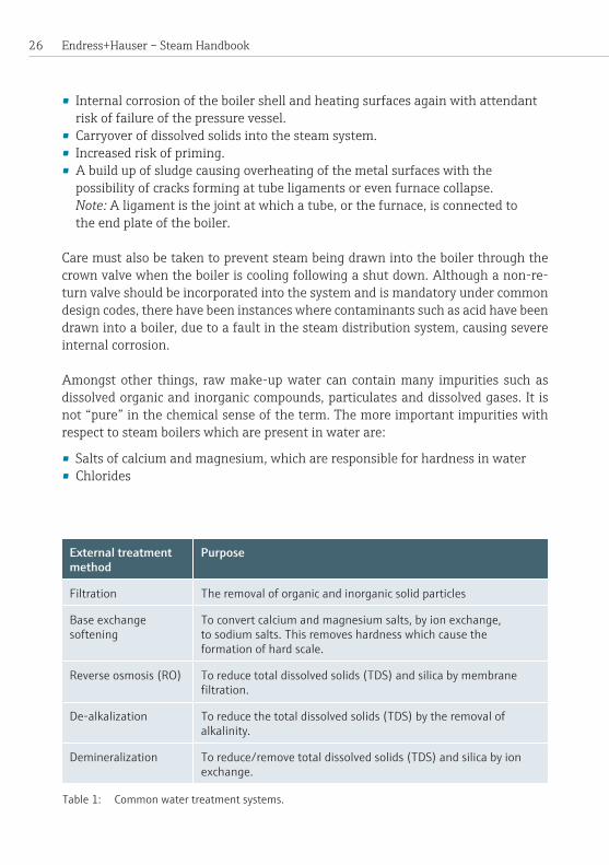
External treatment method
Purpose
Filtration The removal of organic and inorganic solid particles
Base exchangesoftening
To convert calcium and magnesium salts, by ion exchange, to sodium salts. This removes hardness which cause the formation of hard scale.
Reverse osmosis (RO) To reduce total dissolved solids (TDS) and silica by membrane filtration.
De-alkalization To reduce the total dissolved solids (TDS) by the removal of alkalinity.
Demineralization To reduce/remove total dissolved solids (TDS) and silica by ion exchange.
Table 1: Common water treatment systems.

27Types of industrial steam boilers
•Ammoniumsaltsandtheirproductsofoxidation,nitritesandnitrates• Traces of heavy metals such as lead or copper•Dissolved gases, such as oxygen and carbon dioxide
The water treatment process for a steam boiler is usually in two stages – external or internal treatment:
External treatment is used to condition the feedwater supply to the boiler for a va-rietyofreasons,onesuchbeingsofteningtoremovecompoundswhichformhardscale.De-aeration,primarilytheremovalofoxygen, isalsovery importantandisachievedbyacombinationofthermalandchemicalconditioningofthefeedwater.The feedwater is further conditioned by the addition of various compounds such asalkalinitybuilderstopreventcorrosion,andsludgeconditioners.Table1givesa briefdescriptionofthemorecommonprimarywatertreatmentsystemsinuse.
Internal treatment: Assteamboilersexportrelativelypuresteam,thevariouscom-pounds in the water and chemicals added to it concentrate inside the boiler with timeeitherinsolutionorsuspension.Toogreataconcentrationoftotaldissolvedsolids (TDS) will cause foaming, carryover and, depending upon the water level con-trolsystemmaycausefalsepositivelevelconditions.Thelevelofdissolvedsolidsiscontrolled by automatic or manual blowdown in conjunction with appropriate test-ingoftheTDS.
Someofthesolidsintheboilerdepositassludgeatthebottomoftheshell.Thisisremoved by a bottomblowdownvalvenormallyoperatedonceaday.Failuretobot-tomblowdowntheboilermaycausethebottomofthefurnacetobecomefilledwithsludge, which will then build up and insulate the heating surfaces which may cause localizeddamageormoreseriouslyafurnacecollapse.
Deposits on the steel surfaces inside the boiler may occur due to defective water treatmentortosomeformofcontaminationofthereturnedcondensate.Controlof thesedeposits isofhigh importance inorder tomaintain theefficiencyof theheat exchange surfaces within the boiler and reduce the risk of a dangerous occur-rence.Alayerofscaleontheheatingsurfacesofaboiler,forexample,wouldserveto insulate them as the thermal conductivity of scale is about one hundredth of that ofsteel.Thiswouldcausemetaltemperatureoftheheatedsurfacesofthepressurevessel tobehigher than intended.Thismorecommonlyreducestheefficiencyoftheboilerandmayrequireexpensiveremediationwork.Inextremecases,however,the scale can be so thick that the metal temperature of the furnace in particular increases to the point where it becomes plastic and it collapses due to the external watersidepressure.

Endress+Hauser – Steam Handbook 28
Contamination of condensateCondensate is returned to the boiler house for re-use because it should be water of highpuritywithasignificantheatcontent.However it ispossibleforcondensatetobecomecontaminatedwithundesirableconsequences.Therearetwofrequentlyencountered scenarios:
Scenario 1: Thecontaminationisknownandaccepted.Anexamplefromindustrycould be the recovery and re-use of condensate from steam ejectors used to evapo-rate milk.The “evaporate” from themilkmixeswith theprime steamand is re-turned to theboilerhouse in the condensate.This condensatewill contain somecontaminationsuchasfatsfromthemilk.Thisisacceptedduetothehighmonetaryvalueof thecondensate.However, there isconsequentlya riskof foaming insidetheboilerduetothepresenceofthefatsinthecondensate.Dependentontheexactconditions (contaminant and controls) there may be a contingent risk that the level controls are fooled into measuring the foam level rather than the true water level resulting ina low-waterevent. In thisscenarioselectionof themostappropriatelevel controls and close control of the total dissolved solids (TDS) inside the boiler areofcriticalimportance.
Scenario 2: Contaminationduetosomefailurewithinthesteamplant.Anexamplecould be a heat exchanger used for cleaninginplace(CIP).Ononesideoftheheatexchanger iscausticsodaandsteamontheother. If theheatexchangerelementfails, caustic soda could be drawn into the boiler through the condensate return system.ThisagainmayhaveundesirableconsequencesforthepHlevelandcertaintypesoflevelcontrols.Goodpracticeandcertainregulatoryregimesadvisethattherisks due to contaminated condensate should be assessed and if necessary appropri-atecontrolmeasuresintroduced.Thesecouldinfluencetheselectionoftheboilercontrolsandalsomonitoringandcontrolofcondensateforcontamination.
Level controlsCorrectly functioning level controls are of critical importance to the safe operation ofaMTHSboiler.Low-waterincidentsduetodemandrelatedcauses,suchasprim-ing,arerelativelyfrequentinindustry.Whilsttheyrarelyposeadangertotheboileritself, they may result in the burner being shut down requiring manual reset with a potentialconsequentlossofproduction.Ofgreatersignificanceisacompletefailureof the level controls which can cause a furnace collapse or even a catastrophic failure (explosion).Dangerousoccurrencesandthemuchlesscommoncatastrophicfailureduetoalow-waterleveleventcanhavemultiplecauses.Suchcausescanbefairlysimple such as faulty repair, or more complex, such as equipment failure causing contaminationintheprocess,whichinturndefeatsthecontrols.

29Types of industrial steam boilers
Thereareanumberofdifferentcommonlyusedlevel control types, each of which hasitsownstrengthsandweaknesses.Oneofthemostcommonlevelcontrolsys-tems in Europe comprises fail safe, high integrity self-monitoring conductance and capacitancearrangements.Withthesetypesofcontroltheboilershellformspartoftheelectricalcircuit.Thesehavelargelydisplacedfloattypecontrolshousedinexternalchamberswhichpreviouslydominatedthemarket.Developmentsinlevelcontrols and limiters have meant that other principles are becoming more common intheboilerindustry.Examplesareinternaldisplacementfloats,guidedradarandvibratingfork.Theprecisetypeofcontrolsusedonagivensiteshouldbedeterminedbytheenduseratspecificationthroughsuitableriskanalysisandbecapableofde-fendingagainstalltheidentifiedthreats.
Feedwater pump arrangements
On-OffcontrolsAsthenameimpliesthewaterpumpiseitherrunningatmaximumcapacityorisswitchedoff.Thesearegenerallyonlyfittedtosmallboilersduetoproblemsassoci-atedwiththermalshockinlargerboilers.Theyarenotrecommendedforusewherelargefluctuationsinloadmaybeexperienced.Theinjectionofalargequantityofrelatively cold water in combination with a sudden demand change may cause the steam bubbles under the surface of the water to collapse, lowering the overall level andtriggeringalow-watercut-outoftheburner.Theymustnotbeusedinconjunc-tionwitheconomizers.
Modulating controlsThereareseveralmethodsofmodulatingthefeedwaterflowratetotryandmatchthesteamoutput.Thesimplestmethodistofitavariablespeeddrivetotheelectricmotor of the feedwater pump.This ishowever frequently limited in the amountofturndownthatcanbeprovidedduetothetypesofpumpnormallyselected.Anincreaseinturndownisoftenachievedbytheinclusionofacontrolvalveintothesystemwhichregulatestheflow.Ifaneconomizerisfittedtotheboiler,aspillbacktothehotwellordeaeratormayberequired.
Afurtherimprovementtothefeedwatermanagementcanbeobtainedthroughtheuseofthree-elementcontrol.Inadditiontothelevelcontrols,inputsmaybetakenfrom feedwatermeters, steammetersandpressure transmitters.Threeelementsystemsattempttoanticipatethewaterdemandandresultinamoreevenflowoffeedwater to the boiler, reduce thermal shock and improve the response of the boiler tochangesindemand.

Endress+Hauser – Steam Handbook 30
BurnersMTHSboilerscanbedesignedtofirealmostanysolid,liquidorgaseousfuelwithaneconomicallyextractablecalorificvalue.Commonfuelsarenaturalgas,dieselandlightfueloil.Heaviergradesoffueloilaremorecommonlyfoundinmoreremoteinstallationsespeciallythosenotconnectedintoanaturalgassupplysystem.Heavyfueloilplantsareassociatedwithhighercapitalcosts,handlingdifficultiesandmoreintensive operational requirements and are becoming less common in Europe due to increasingregulatorydemandsinrelationtopollution.Coal,refuse/waste-derivedfuels, bio fuels and alternative grades of gaseous and liquid hydrocarbon fuels are alsoused,generatingimportantnichefuelmarketsfortheboilerindustry.
MTHSboilersareusuallyfittedwitheithersingleordual-fuelburners,whilstburn-erswithamulti-fuelcapabilityareavailabletheyaremuchlesscommon.Depend-ingonthespecification,veryclosecontrolandhighlyconsistentoperationmaybeachieved by the incorporation of fuel-air-mapping systems coupled with servo-mo-tor controlled modulating damper systems and oxygen trim with a variable speed driveonthemotor.Thesecanofferturndown ratios of up to 10:1 on natural gas, and 6:1 on lighter grades of oil whilst being able to consistently maintain excess oxygenlevelsbelow15%.
Care should be taken to match a burner to a given boiler furnace. A correctlymatched burner–furnace combination will deliver improved performance and econ-omywhilstminimisingtheemissionsofunwantedpollutants.Thiscanbeespeciallyimportant for burners designed for very low emissions, primarily oxides of nitro-gen, for which design considerations such as the furnace shape, burner head design, flameshape,air/fuelstagingandinternalre-circulationarebalancedwithachiev-ableminimumexcessair,carbonmonoxidelevelsandflamestabilitythroughouttheturndownrange.
Initssimplestformtheburnerfiringrateisafunctionoftheboilerpressureonly.If we consider a boiler which is at its upper set point, maximum working pressure, withthecrownvalveclosedthentheburnerwillnotbefiring.Ifthecrownvalveisopenedandsteamexportedthepressurewillstarttofallinsidetheboiler.Whenthispressure falls to a pre-determined set point the burner will commence its ignition sequenceandfireup.Theburnerwillthenremainfiringuntilitreachesmaximumworkingpressureatwhichitstopsfiring.Ifthepressureinsidetheboileragainfallstheburnerwillre-startautomaticallyandtheprocesswillkeeprepeatingitself.
If the burner is capable of modulation, it will try to maintain a set point just under theuppersetpointsothatitremainsfiringcontinuouslyunlessthesteamdemand
31Types of industrial steam boilers
issolowthatitisbelowtheburner’sminimumturndownthusforcingthepressuretoreachmaximumworkingpressurewhichturnstheburneroff.
Ifthesteamdemandissogreatthatitexceedstheburner’sabilitytoaddheatandthusmaintainpressure,theburnerwillkeepfiringatitsmaximumfiringratebutthepressurewillnotbeabletorecoverandwillfall.Thepressurewillkeepfallinguntiltherateofheatremovedinthesteamequalsthataddedbytheburner.Thismeans that lower pressure steam (lower than is required) is distributed with poten-tial consequences which can include steam starvation to the end processes, exces-sivesteambulkvelocityandcarry-overofliquidsandsolids.The principal safety features associated with burners are:
• Pre-firecheckssuchasprovingthevalvesonthegastrainduringthestartupsequence
•Airprovingwhichchecksthatthevolumeofairpassingthroughtheburner atasetfanspeedanddampersettingiscorrect.
•Apre-firepurgeduringwhichairisblownthroughtheboilerremovinganycombustible gases
•Aflamedetectorwhich,intheeventofaflameoutevent,shutstheburnerdownrequiring manual reset (a lock-out)
• Fail-safe slam shut valves on the fuel lines which deploy in the event of a dangerousoccurrencesuchasafire
• In addition, the waterside limiters such as pressure and level will, when deployed, force the burner to shut down locking out the boiler requiring a manualreset.

Endress+Hauser – Steam Handbook 32
33Basic steam distribution
Basic steam distributionSteammovesfromahighpressurelocationtoalowerpressurelocation.Indoingsoitusessomeofitsownenergywhichisseenaspressuredrop.Additionally,heatlosses during distribution causes a fraction of the steam to condense to form con-densate.Thisisfundamentaltounderstandingtheoperationofsteamsystemsandhowtheyaredesigned.
As steam, by its nature, is generated at elevated pressure and temperature, thewholesystemhastoberatedforthemaximumdesignpressureandtemperature.This is normally achieved by designing or selecting parts and equipment that con-formtopublisheddesignstandards.
Afurtherveryimportantconsiderationisthedesignbulklinevelocityofthesteamwhichislimitedtopreventundulyfasterosion,forsteamisaveryaggressivefluid.Asa“ruleofthumb”steambulkvelocitiesarenormallylimitedforsaturated/wetsteamtobetween25and40m/sforshortlinesand15to20m/sforlongerlines;thepreciselimitingvelocitybeingchosenbytheindividualdesignengineer.Oncethe limiting velocity is selected the line sizes can be calculated based on the steam pressure(andhenceitsdensity)andtherequiredmassflowratefortheapplication.
The condensate which forms as a result of primarily heat loss and secondarily the motionofthesteammustberemoved.Thisisachievedbyusingasteam trap – a devicetoseparateliquidwaterfromsteam.Withinthedistributionsystem,steamtrapsarefittedatregularintervalsinso-called“dirt-legs”–averticalpipelegwhichallows the denser condensate to collect at the bottom from which it is removed by the trap. To aid removal of condensate, steam lines should always befitted at aslightdownwardangleinthedirectionofflow.Asaruletheminimumfallshouldbe1:100.Inordertominimizetherateofcondensateformation,steamlinesshouldalwaysbe insulated. Insulationof steam lineswillalso reduce thesurface touch-temperaturetoapointwhereitwillnotcauseburnstoskinoncontact.
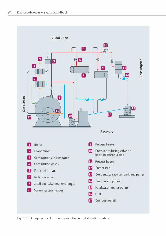
There are a number of items of basic line equipment which are common to all steam systems (Figure 11).The following list includesonly themostbasic typesof lineequipment:
Safety valvesThese are valves which discharge to atmosphere in the event that they encounter apressurehigherthantheirsetpressure.Theyareveryimportantastheypreventoverpressure either on vessels such as steam boilers, pressure vessels or down-streamofpressurereducingvalves.
Endress+Hauser – Steam Handbook 34
Distribution
Cons
umpt
ion
Gene
ratio
n
Recovery
Combustion gases
Economizer
Combustion air preheater
Boiler
Forced draft fan
Isolation valve
Shell and tube heat exchanger
Steam system header
Steam trap
Pressure reducing valve orback pressure turbine
Process heater
Process heater
Condensate receiver tank and pump
Condensate piping
Feedwater heater pump
Fuel
Combustion air
Figure 11: Components of a steam generation and distribution system.

35
Isolation valvesThesearesimplyvalveswhichpermitordenyflow.Theycanbeeithermanualorautomatic in operation and are used extensively in steamplants.Duringnormaloperationtheyshouldalwaysbeeitherfullyopenorfullyclosed.Ifasystemisbeingwarmed up, steam valves should be fractionally opened to permit a small amount of steam through so that the lines are heated slowly and gently as this reduces the riskofwaterhammerevents.Valveswhicharefractionallyopenedforthispurposeshouldalwaysbeundersupervision.Isolationvalvesarevitalwhenplantisbeingisolatedforworkonthesteamsystem.Theselectionofappropriatesystemsofplantisolation is extremely important and care should be taken to ensure that an isolation systemusedforaparticularjobisadequate.Undernocircumstancesisitappropri-atetoworkonasteamsystemusingasingleclosedisolationvalve.
Control valvesThesearevalveswhichregulatetheflowofsteam.Theymaybemanualorauto-maticinoperation,althoughinindustrialsettingsthevastmajorityareautomatic. Note: valves designed or installed only for isolation should not be used for control purposes.
Pressure reducing valves (PRV)Steammovesbygivingupsomeofitsownenergy.Consequentlyitisalmostimpos-sible to design a system with a known, controllable pressure at the point of con-sumptionunlesspressurereducingvalvesareincorporated.Pressurereducingvalvesareusedtoreducethepressuretothatrequiredclosetothepointofconsumption.Pressuregaugesandsafetyvalvesshouldalwaysbefitteddownstreamofthem.Thecomplete set of valves and other equipment associated with a PRV are frequently referredtoasapressurereducingsetorstation.
Pressure and temperature gaugesThese are found in abundance on steam systems so that the plant operators know theconditionofthesteam.Theymayalsobeusedforcontrolpurposes,e.g.pressuregaugesdownstreamofcertaintypesofPRVsareusedinthefeedbackloop.Note: temperaturegaugesarenormallyonlyusedonsuperheatedsteamsystems.
Non-return valves/check valves Steamandcondensateshouldonlyflowinonedirection–thatintendedbythede-signer.Thesevalvesareusedtoensurethatthis isso.Theyare importantpiecesofequipmentastheycanpreventunwantedorpotentiallydangerousoccurrences.
Basic steam distribution

Endress+Hauser – Steam Handbook 36
Strainers Steamisaggressiveanderodessteampipes.Strainersareusedtofilteroutanyde-bristhatmaybecontainedinthesystem.Theyarefrequentlyfoundlocatedinfrontofcontrolandreducingvalves.Theyshouldalwaysbeincludedintrapsets.
Steam traps Assteammovesthroughasystemsomeofitcondensesintoliquidwater.Thisliq-uidwatermustberemovedforavarietyofreasons.Thisisdoneusingsteamtraps,devices which are capable of separating liquid water from steam and discharging it intoacondensatelineforreturntotheboilerhouseordisposal.Theyarealsofittedtoallindirectconsumersofsteam.Theircorrectoperationisvitaltothefunctioningofasteamsystem.Trapsarenormallyfittedinconjunctionwithotherequipmentsuchas sight-glasses, strainers, checkand isolation valves.Collectively theseareknownas“trapsets”.Itisveryimportantthatsteamtrapsareinspectedonaregularbasis.Itisestimatedthat15%faileveryyear,andthereareanumberofundesirableconsequences,botheconomicandsafety,whichresultfromfailedtraps.

37
How steam moves (simple explanation)Inthefollowingtexttheresultsofcalculationsaremerelystated.Thederivationsofthese calculations can be found on Pages 41ff.
Suppose we have dry saturated steam held in a reservoir at 10 bara and that this reservoir can be expanded (Figure 13).When the reservoir is expanded – usingexternal work –, the steam also expands and work is performed by the steam in itsexpansion.Asthisisaclosedsystem,i.e.thereisnoenergytransferredintoorout of the steam, the energy required for the expansion of the steam must come from the steam itself.When the reservoir expands, the pressure decreases, andforthisexampleweshallassumeafinalpressureof9bara.Thetotalenthalpyofthe steamat the initial condition is the sameasat thefinal condition.The totalenthalpy of the dry saturated steam at 10 bara is 2777 kJ/kg, and its tempera-tureis179.9°C(fromsteamtables).Asthereisnochangeinenergy,thesteam–once the pressure has fallen – still contains the same amount of energy as it had at thestart.However,drysaturatedsteamat9barahasasaturationtemperatureof175.4 °C and contains2774kJ/kg, 4 kJ/kg less than at 10 bara. This differenceshowsitselfassuperheat,i.e.thetemperaturerisesabovethesaturationtempera-tureat9baraand175.4°C.Thistemperaturerisecanbecalculatedtobe1.5Kofsuperheatforthissituation.Thisgivesafinalsteamtemperatureof175.4°Cplus1.5Kwhichequals176.9°C.
Why does this happen?Workandheataredifferentformsofthesamething:namelyenergy!Ifthereservoiris expanded, the steam inside the system must expand with the physical bound-aryinordertomaintaintheequilibriumofthereservoir.Forthesteamtoexpand,work must be performed, and the energy required for this work must come from the steamitselfasitisinaclosedsystem.
Initially the energy of the system can be thought of as potential energy, observed physicallythroughthepressureandtemperatureofthesteam.Since, initiallythesystemisinequilibrium,thekineticenergyofthesystemiszero.Whenthesystemboundary is physically moved, the steam also moves, and some of this potential energyisconvertedintokineticenergy.However,whenthesystemisagainatrestthereisnomotionandthekineticenergyreturnstozero.Theenergythatwascon-vertedintokineticenergyhastobeconvertedintoanotherformofenergy.Inthiscase,heatandweobservethisheatassuperheat.Thisenergyconversionprocessis:potentialenergytokineticenergytoheatenergy.
How steam moves (simple explanation)

Endress+Hauser – Steam Handbook 38
Ifweconsiderdrysaturatedsteaminitiallyat10bara,andflowingalongapipeuntilthe pressure had decayed to 9 bara, the frictional heating (seen as superheat) deter-minedinthepreviousexample(1.5K)wouldbeseenifthesystemwasalsoclosed,i.e.isenthalpic.However,inpracticeheatislostacrossthepipewall,andinrealitytheprocessesarenotidentical.Althoughfrictionalheatingisstillgenerateditisnotseenassuperheatduetothecoolingeffectofheatlosstoatmosphere.Note: Whilsttheactualrateofheatlosstoatmospherefromasteampipeisdifficulttocalculateexactly,wecanestimateitquitewellforknownconditions.
We can illustrate what happens in a more realistic situation: If we calculate the pressure drop resulting from the passage of steam down a pipe, we can estimate thelinelengthrequiredforthispressuredrop.Forexample,apressuredropfrom 10barato9baraat20m/sinaDN100linewillrequire848metersofpipe(mak-inganassumptionabouttheroughnessofthewall)givingafrictionalheatingeffect ofabout4W/m.
If we then calculate the heat loss for the above case for an insulated pipe, assuming benignconditions,i.e.stillair,wecanestimatetheheattransfertotheatmospheretobe126W/m.Thisisverylargewhencomparedtothefrictionalheatingeffectofapproximately4W/mandsothesuperheatisnotseen.Foruninsulatedpipes,theheatlossisatleastanorderofmagnitudegreaterthanforinsulatedpipes.
Asyoucansee,thetemperatureincreaseduetofrictionalheatingisverysmallforconditionstypicallyfoundinsaturatedsteamsystems.Whenexpressedinenergyterms, it can readily be seen that superheat generation is easily “masked” by the heat loss from the pipe wall which approximates to an order of magnitude greater thantherateofsuperheatgenerationfortheinsulatedpipecase.Giventhatsteamlinesareextremelydifficulttofullyinsulate,superheatsolelyduetothepassageofsteamthroughapipeisthereforehighlyunlikelytobeseeninpractice.
Sofarwehaveneglectedtoconsidertheeffectofheatlossthroughthepipewallson the steam itself. Let us take our 10 bara steam travelling at 20m/s down a DN100pipe:Itrequires848meterforthepressuretodropto9baraduetofriction.However, over that length of 848 meter some 106 kW of heat would be lost from thesteamtotheatmosphereifthepipewereinsulatedandnearly6.5%ofthesteaminthelinewouldhavecondensedbackintocondensate(liquidwater).
Althoughitisinpracticenotpossibletoobservesuperheatduetopipefrictionlossesalone in a steam line, superheat is frequently found in what are normally thought ofassaturatedsteamsystems.Thisisduetothepresenceoflineequipmentacrosswhich there is a largepressuredrop.Themostobviousand frequentlyoccurringexampleofthisisapressurereducingvalve(PRV).

39
There are a number of reasons why PRVs are used in industry. The one which concerns us here is the need to provide a stable and controllable steam system sup-plytoeachofmultipleconsumersfromoneoverallgenerationsource(boiler).Thepurpose of a PRV is to provide a stable steam pressure down stream of the valve over arangeofmassflowratesandwithapotentiallyvariableupstreampressure.
ExampleLet us suppose a typical situation (Figure 12): Upstream of a PRV the steam is satu-ratedwithapressureof9baraat175.4°Candthedownstreampressureis4bara.IfweapproximateanolossconditionacrossthePRV,thedifferenceinspecificenthal-py of the 9 bara saturated steam compared to the 4 bara saturated steam is so great that some 16 degrees of superheat are generated, and the 4 bara steam is super-heatedratherthansaturated.Note:Thefinaltemperatureofthe4barasuperheatedsteamisthesaturationtemperatureofsaturatedsteamat4bara(143.6 °C)plusthedegreesofsuperheat(16K)whichgivesafinalsteamtemperatureof159.6°C.
Thus, rather than the extremely small rate of superheat generation due to frictional line losses, we may now have a large and measureable amount of superheat im-mediatelydownstreamofthePRV.Itisveryimportanttorealizethatthissuperheatiscausedbythepassageofthesteamthroughthevalve. If there isnoflowthenthereisnosuperheatformation.Iftheflowrateisextremelylowthentheheatlossthroughthevalvebodywouldmaskthiseffecttosomedegree.However,fortypicalsteambulkvelocities,itisquitepossibletoobservethiseffectdownstreamofPRVsin industry simply by measuring the temperature and pressure of the superheated steamandthenlookingupthesevaluesinasetofsteamtables.
How steam moves (simple explanation)
Figure 12: The passage of steam under isenthalpic conditions through a pressure reducing valve (PRV) for known conditions.
Q = 0
Saturated steam (9 bara)hg = 2774 kJ/kgTsat = 175.4 °C
Superheated steam (4 bara)hg = 2774 kJ/kgTsat 4 bara = 143.6 °C°superheat = 16 KTfinal = 159.6 °C

Endress+Hauser – Steam Handbook 40
Approximation to no loss condition: For the case of 9 bara steam travelling at 20m/sdownaDN100linetheflowofheatwillbegreaterthan2MW.Typicalcasing losses from a suitably sized PRV will be around 2 kW – around three orders ofmagnitudelessthantheflowofheatinthepipe.Therefore,thesuperheatwillremain in the steam and be dissipated by heat loss as the steam travels further downstream.
How long will the superheat endure? Superheat, if generated in significant quantities can persist for a significant dis-tance.Evenforanuninsulatedline,itispossibleintheoryfortheretobesuperheataconsiderabledistancefromthePRV,forexample,at20m/sforinsulatedpipelinesupto151meters,andforuninsulatedpipelinesupto18meters.
Inpractice,aspreviouslynoted,steamlinesareoftennotcompletelyinsulatedandthesuperheatdissipationlengthwillbeshorter.Moreover,anycondensatethatwasinthesteamlineupstreamofthePRVwillalsohaveasignificanteffect,asitcanpass throughthevalveandthenasmallamountwillboilofftoquicklydissipatethesuperheat.Thisdoesnothappeninstantaneously; it ispossibleforwetsteamto pass through a PRV, and downstream for there to be superheated steam in the centreofthepipewithliquidwateradheringtothewalls.Therewillthenbeamix-inglengtheffectbeforethesuperheatisdissipatedbythelinelossesandboilingofthecondensate.
Alllineequipmentexhibitthiseffectasthereisamuchgreaterpressurereductionthrough lineequipment compared topipe friction losses.This superheatgenera-tionmaybeunanticipated.AnexampleofapredictablesuperheatcreatedbylossesthroughequipmentotherthanaPRVwouldbethebluffbodyofavortexflowmeterortheorificeplateofaDPflowmeter.
An example of an unanticipated situationwould be a partially opened isolationvalve (note: these should be either fully open or fully closed): In this instance there is an unexpectedly high pressure drop across the valve which causes superheat to occurdownstream. It isquitepossible for this tohappen,and for the steamsys-temtooperateeffectively,becausetheyareintentionallydesignedwithanexcessofpressure.Alternatively,apartiallyopenedisolationvalvemaycauselocalstarvationdownstream as the pressure drop is too great to allow the required amount of steam through.

41
On the motion of steam (detailed explanation)Let us suppose that 1 kg of dry saturated steam is held in a reservoir at 10 bara (Figure 13, a) and that this reservoir can be expanded using external work so that the steam is under adiabatic, isenthalpic conditions in a closed system with the boundaryastheinternalwall.Note: The work required to move the physical boundary is provided from an external source, no work is performed on the steam itself and no heat is transferred to or fromthesteam.
When the reservoir is expanded, the steam also expands, and work is performed in expanding the steam (Figure 13, b).Asthisisaclosedsystem,i.e.thereisnoheattransfer across the boundary and the process is adiabatic, the energy required for theexpansionofthesteammustcomefromthesteamitself.Whenthereservoirexpands, we see that the pressure decreases and for this example we shall assume a finalpressureof9bara(Figure 13, c).
Wecan calculate thephysical changes to the steam: the specificenthalpyofdrysaturatedsteamvaporat10bara is2777kJ/kgandasaturation temperatureof179.9°C.Asthereisnochangeinthetotalenthalpyofthesteam,oncethepressurehasfallento9baraitmuststillcontain2777kJ/kg.However,drysaturatedsteamvaporat9barahasaspecificenthalpyof2774kJ/kgandasaturationtemperatureof175.4 °C.Thedifferencebetweenthespecificenthalpyofthevaporatthetwopressures–4kJ/kg–isexhibitedassuperheat,i.e.thetemperaturehasrisenabovethesaturationtemperatureat9bara175.4 °C.Thistemperaturerisemaybecal-culatedusingthespecificheatcapacityofthesubstanceaccordingtoEquation(1).
(1)
Takingthespecificheatcapacityofthesteamvaporas2.7kJ/kgKandthemass of steam as 1 kg – when Equation (1) is rearranged into Equation (2) –, the tem-perature rise is 1.5K of superheat giving afinal steam temperature of 175.4 °C +1.5K=176.9°C.
(2)
Why does this happen?For this fact we require some understanding of both the First and Second Laws of Thermodynamics.TakingtheSecondLawofThermodynamics,itmaybesaidthatacorollaryofthislawisthatallthermodynamicsystemstendtowardsequilibrium.
( )
( )
On the motion of steam (detailed explanation)

Endress+Hauser – Steam Handbook 42
Consider our system with the previously described 1 kg of dry saturated steam at 10 bara (Figure 13, a). It is internallyatrestandnoheatorworkiscrossingthethermodynamicboundary,ergoitmaybesaidtobeinequilibrium.Ifthereservoiris expanded by doing work external to the system, then, a void would be created if the steam did not expand and the system would be out of equilibrium as there wouldbetwovolumeseachwithadifferentpressurebutnoboundarybetweenthem (Figure 13, b).Thus the steam inside the systemmustexpandwith thephysicalboundary in order to maintain the equilibrium of the internal system (Figure 13, c).
Initial condition (equilibrium)Q = 0
Thermodynamicboundary
Saturated steamat 10 bara
W = 0
System out of equilibriumQ = 0
Thermodynamicboundary
Saturated steamat 10 bara
Final condition (equilibrium)Q = 0
ThermodynamicboundarySaturated steam
at 9 bara and1.5 K superheat
W = 0
W = 0
Figure 13: Thermodynamic state of a system – equilibrium during expansion.
(a)
(b)
(c)

43On the motion of steam (detailed explanation)
FromtheFirstLawofThermodynamics,wecanseethatworkandheataredifferentformsofthesameentity:namelyenergy.Energycannotbecreatednordestroyed,merelychangedfromoneformtoanother.Also,forthesteamtoexpandinaccor-dance with the First Law of Thermodynamics work must be performed and, as noted previously,theenergyrequiredforthisworkmustcomefromthesteamitself.
Initially for the condition shown in Figure 13 (a), we may consider that the energy of the system is in the form of potential energy, observed physically through the pressureandtemperatureofthesteam.Asthereisnomotionthekineticenergyofthesystemiszero.Whenthesystemboundaryisphysicallymoved,thesteamalsomovesandsomeofthispotentialenergyisconvertedintokineticenergy.However,when the system is again at rest there is no motion and the kinetic energy returns tozero.InordertosatisfytheFirstLawofThermodynamics,theenergythatwasconverted into kinetic energy is further converted into heat and it is this heat that isexhibitedassuperheat.Thisprocess,i.e.conversionofpotentialenergytokineticenergy, and then to heat energy, can be derived from consideration of the First Law ofThermodynamicsandexpressedintermsofEquation(3).
(idealized isenthalpic conditions) (3)
If we consider saturated steam taken from a boiler or accumulator (a reservoir) which ismaintainedat10bara, andflowingalongapipeuntil thepressurehasdecayed to 9 bara, the above results would be also true if the situation was also isenthalpic,i.e.thefinalconditionofthesteamwouldbe9barasteamwith1.5K superheat.However,inreality,heatislostacrossthesystemboundary(pipewall)andtheprocessisnotisenthalpic.
Wecanusestandardtheorytoillustratewhathappensinamorerealisticsituation.Note: whilsttheactualrateofheatlosstoatmospherefromasteampipeisdifficultto calculate exactly, standard theory permits a good approximation to be estimated forknownconditions.
The Darcy-Weisbachequation(Kreith1972,p.376),Equation(4),isusedtoesti-matethepressuredropresultingfromthepassageoffluiddownapipe.Thiscanbe rearranged and used to estimate the line length (l), resulting in a corresponding pressuredrop.Letussupposethattheoverallpressuredropis1barforarangeofinitial pressures of dry saturated steam and typical bulk velocities for a DN 100 bore steamline.Forthiscalculationweshallrequireafrictionfactor.Inthisexamplethis factor is calculated using an approximation, that of Petukhov (Petukhov 1970) mod-ifiedtocalculatea“British”frictionfactor,Equation(5).Theresultinglinelengths areshowninTable2(forsaturatedsteam).Thefrictionfactorscalculatedforthe
Endress+Hauser – Steam Handbook 44
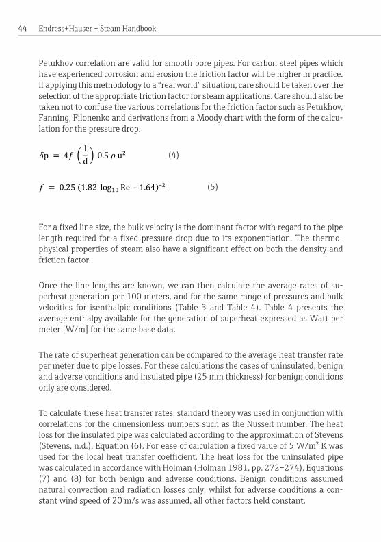
Petukhovcorrelationarevalidforsmoothborepipes.Forcarbonsteelpipeswhichhaveexperiencedcorrosionanderosionthefrictionfactorwillbehigherinpractice.If applying this methodology to a “real world” situation, care should be taken over the selectionoftheappropriatefrictionfactorforsteamapplications.Careshouldalsobetaken not to confuse the various correlations for the friction factor such as Petukhov, Fanning, Filonenko and derivations from a Moody chart with the form of the calcu-lationforthepressuredrop. (4)
(5)
Forafixedlinesize,thebulkvelocityisthedominantfactorwithregardtothepipelength required forafixedpressuredropdue to its exponentiation.The thermo-physicalpropertiesofsteamalsohaveasignificanteffectonboththedensityandfrictionfactor.
Once the line lengths are known, we can then calculate the average rates of su-perheat generation per 100 meters, and for the same range of pressures and bulk velocities for isenthalpic conditions (Table 3 and Table 4). Table 4 presents the average enthalpy available for the generation of superheat expressed as Watt per meter[W/m]forthesamebasedata.
The rate of superheat generation can be compared to the average heat transfer rate permeterduetopipelosses.Forthesecalculationsthecasesofuninsulated,benignand adverse conditions and insulated pipe (25 mm thickness) for benign conditions onlyareconsidered.
To calculate these heat transfer rates, standard theory was used in conjunction with correlationsforthedimensionlessnumberssuchastheNusseltnumber.Theheatloss for the insulated pipe was calculated according to the approximation of Stevens (Stevens,n.d.),Equation(6).Foreaseofcalculationafixedvalueof5W/m²Kwasusedforthelocalheattransfercoefficient.TheheatlossfortheuninsulatedpipewascalculatedinaccordancewithHolman(Holman1981,pp.272–274),Equations(7) and (8) for both benign and adverse conditions. Benign conditions assumed natural convection and radiation losses only, whilst for adverse conditions a con-stantwindspeedof20m/swasassumed,allotherfactorsheldconstant.
( )
( )

45On the motion of steam (detailed explanation)
Initial pressure
Final pressure
Pipe length [m] required for a 1 bar pressure drop Average bulk velocity
[bara] [bara] 10 m/s 15 m/s 20 m/s 25 m/s 30 m/s
3 2 8408 4062 2419 1617 1162
4 3 6503 3134 1864 1244 894
5 4 5360 2579 1532 1022 733
6 5 4589 2205 1309 872 626
7 6 4029 1934 1147 764 548
8 7 3602 1727 1024 682 489
9 8 3264 1564 927 617 442
10 9 2989 1432 848 564 404
11 10 2761 1321 782 520 373
12 11 2567 1228 727 483 346
13 12 2401 1148 679 452 323
14 13 2258 1079 638 424 304
15 14 2131 1018 602 400 286
16 15 2018 964 570 379 271
17 16 1919 916 541 360 257
18 17 1829 873 516 343 245
19 18 1748 834 493 327 234
20 19 1673 798 471 313 224
Table 2: Line lengths [m] required for a pressure drop of 1 bar (DN 100 pipe).

Endress+Hauser – Steam Handbook 46
Initial pressure
Final pressure
DN 100 pipe superheat/100 m line [K/100 m] Average bulk velocity
[bara] [bara] 10 m/s 15 m/s 20 m/s 25 m/s 30 m/s
3 2 0.104 0.216 0.363 0.543 0.755
4 3 0.092 0.190 0.320 0.479 0.667
5 4 0.082 0.170 0.287 0.430 0.599
6 5 0.074 0.154 0.260 0.390 0.544
7 6 0.068 0.141 0.237 0.356 0.497
8 7 0.062 0.129 0.218 0.327 0.456
9 8 0.057 0.118 0.200 0.300 0.419
10 9 0.052 0.109 0.184 0.277 0.387
11 10 0.048 0.101 0.170 0.255 0.356
12 11 0.044 0.093 0.157 0.236 0.329
13 12 0.041 0.085 0.144 0.217 0.303
14 13 0.037 0.077 0.130 0.196 0.274
15 14 0.034 0.072 0.122 0.183 0.256
16 15 0.032 0.066 0.112 0.168 0.235
17 16 0.029 0.060 0.102 0.154 0.215
18 17 0.039 0.082 0.139 0.209 0.292
19 18 0.024 0.050 0.084 0.127 0.178
20 19 0.021 0.045 0.076 0.114 0.160
Table 3: Rate of superheat generation for typical average bulk velocities, idealized isenthalpic conditions (DN 100 pipe).

47On the motion of steam (detailed explanation)
(6)
r = steam pipe outer radiust = insulation thicknessk = thermal conductivity of the insulationα = local heat transfer coefficient over the insulation
(7)
(8)
AsmaybeobservedfromTable3,thefractionoftheinitialenthalpyofthesteamwhich is converted to superheat due to its motion results in the generation of very small amounts of superheat.When rate of superheat generation is expressed inenergy terms and compared to the rate of heat loss for various conditions (Table 4), it can readily be seen that superheat generation is easily “masked” by the heat loss fromthepipewall.Giventhatsteamlinesareextremelydifficulttofullyinsulate,superheat due to the passage of steam along a pipe is very unlikely to be seen out-sideofalaboratory.
Although,inpracticeitisnotpossibletoobservesuperheatcausedbyfrictionlossesduetothepassageofsteamdownapipealone.Superheat isfrequentlyfoundinwhatarenormallythoughtofassaturatedsteamsystems.Thisisduetothepres-ence of line equipment across which there is a large pressure drop; the obvious examplebeingapressurereducingvalve(PRV).
ExampleLetussupposethatwehaveatypicalsituation.UpstreamofaPRVthepressureis 9 bara and downstream it is 4 bara (Figure 14).Moreoverweshallassumeanisen-thalpicor“noloss”conditionacrossthePRV.Thespecificenthalpyof9barasatu-ratedsteamis2773kJ/kg,however,thespecificenthalpyof4barasaturatedsteamis2738kJ/kg–adifferenceof35kJ/kg.Itisthis35kJ/kgthatisavailabletosuper-heatthe4barasteam.Again,wecancalculatetheamountofsuperheatgeneratedtobe15.3KfromEquation(9).
(9)
( )
[ ( )
( ) ]
( )
( )
( )

Endress+Hauser – Steam Handbook 48
Initial pressure
Final pressure
DN 100 pipe: enthalpy conversion [W/m] Average bulk velocity
[bara] [bara] 10 m/s 15 m/s 20 m/s 25 m/s 30 m/s
3 2 0.26 0.80 1.79 3.4 5.6
4 3 0.32 1.01 2.25 4.2 7.1
5 4 0.38 1.18 2.65 5.0 8.3
6 5 0.43 1.33 3.00 5.6 9.4
7 6 0.47 1.47 3.29 6.2 10.3
8 7 0.50 1.58 3.55 6.7 11.2
9 8 0.53 1.67 3.77 7.1 11.8
10 9 0.56 1.75 3.95 7.4 12.4
11 10 0.58 1.82 4.09 7.7 12.9
12 11 0.59 1.86 4.20 7.9 13.2
13 12 0.60 1.90 4.27 8.0 13.5
14 13 0.61 1.91 4.31 8.1 13.6
15 14 0.61 1.92 4.32 8.1 13.6
16 15 0.61 1.91 4.30 8.1 13.6
17 16 0.60 1.88 4.25 8.0 13.4
18 17 0.59 1.84 4.16 7.8 13.1
19 18 0.57 1.79 4.04 7.6 12.8
20 19 0.55 1.72 3.89 7.3 12.3
Table 4: Rate of superheat generation expressed in W/m compared to casing losses (DN 100 pipe).

49On the motion of steam (detailed explanation)
Initial pressure
Final pressure
Casing losses [W/m]
[bara] [bara] 25 mm insulation “benign”
Uninsulated “benign”
Uninsulated “adverse”
3 2 75 626 2642
4 3 88 719 2928
5 4 98 796 3155
6 5 105 863 3347
7 6 112 923 3513
8 7 117 978 3660
9 8 122 1028 3794
10 9 126 1075 3916
11 10 130 1118 4029
12 11 134 1160 4134
13 12 137 1199 4233
14 13 140 1237 4326
15 14 143 1273 4414
16 15 146 1308 4498
17 16 148 1341 4578
18 17 151 1374 4655
19 18 153 1405 4728
20 19 155 1435 4799
(Table 4 continued)

Endress+Hauser – Steam Handbook 50
Thefinaltemperatureofthe4barasuperheatedsteamisthesaturationtempera-tureofsaturatedsteamat4bara(143.6°C)plusthedegreesofsuperheat(16K)whichgivesafinalsteamtemperatureof159.6°CimmediatelydownstreamofthePRV.
Thus, rather than the extremely small rate of superheat generation due to frictional line losses, we now have a large and measureable amount of superheat immediately downstreamofthePRV.
Returning to the assumption of isenthalpic conditions across the PRV – is this as-sumption reasonable? Let us suppose that for the above pressures and degrees of superheataPRVisfittedonaDN100pipewhichhasanestimatedsurfaceareaof0.62m²(derivedfroma3-Dmodelofanactualvalve).AsthisPRVisnotinsulatedwecanestimatetherateofheatlossfromthevalvebodytobearound1.8kW,againusing standard theory, of the form of the previous calculation utilising Equations (7) and(8).
Table5showsthetotalheatflowacrossthePRVandtheheatflowofthesuperheatfractiondownstreamofthevalve.AstheheatlossacrossthePRVissmallincom-parisonwecanseethatithaslittleeffectontheamountofsuperheatimmediatelydownstreamof the valve. For the previously supposed isenthalpic case, the totalsuperheatwascalculatedtobe15.3K.
Figure 14: The passage of steam under isenthalpic conditions through a pressure reducing valve (PRV) for known conditions.
Q = 0
Saturated steam (9 bara)hg = 2774 kJ/kgTsat = 175.4 °C
Superheated steam (4 bara)hg = 2774 kJ/kgTsat 4 bara = 143.6 °C°superheat = 16 KTfinal = 159.6 °C

51On the motion of steam (detailed explanation)
Line speed
Steam mass flow rate
Total heat flow across
the PRV
Heat flow of superheat
fraction after the PRV
Heat loss across the PRV
body
° Superheat immediately downstreamof the PRV
[m/s] [kg/s] [kW] [kW] [kW] [K]
5 0.19 537.8 6.8
1.8
11.2
10 0.39 1075.6 13.6 13.3
15 0.58 1613.3 20.4 13.9
20 0.78 2151.1 27.1 14.3
25 0.97 2688.9 33.9 14.5
30 1.16 3226.7 40.7 14.6
Howlongwill thesuperheatendure?Havingdeterminedtheheatfluxof thesu-perheat fraction, this is simply divided by the line losses (averaged between 4 and 9bara).TheresultsareshowninTable6anddemonstratethatsuperheat,ifgen-eratedinsignificantquantities,willendureforasignificantdistance.Evenforanuninsulated line, it is possible in theory for there to be superheat a some distance downstreamofthePRV.
Inpractice,aspreviouslynoted,steamlinesareoftennotcompletelyinsulatedandthesuperheatdissipationlengthwillbeshorter.Moreover,anycondensatethatwasinthesteamlineupstreamofthePRVwillalsohaveasignificanteffect,asasmallamountwillboilofftodissipatethesuperheat.Thisdoesnothappeninstantaneous-ly and it is possible for wet steam to pass through a PRV and downstream for there to be superheated steam in the centre of the pipe with liquid water adhering to the walls.Therewillthenbeamixinglengtheffectwithinwhichthesuperheatisdis-sipatedbythecondensateandlinelosses.
Alllineequipmentexhibitthiseffectasthereisamuchgreaterpressurereductionthroughlineequipmentcomparedtopipefrictionlosses.Thissuperheatgenerationmaybepredictableorunexpected.
Table 5: Superheat downstream of PRV accounting for casing losses.

Endress+Hauser – Steam Handbook 52
An example of an unanticipated situationwould be a partially opened isolationvalve(note:theseshouldbeeitherfullyopenorfullyclosed).Inthisinstancethereisanunexpectedlyhighpressuredropacrossthevalvewhichcausessuperheat.Itisquitepossibleforthistohappenandforthesteamsystemtooperateeffectivelyastheyareintentionallydesignedwithanexcessofpressure.Alternatively,apartiallyopened isolation valve may cause local starvation downstream as the pressure drop istoogreattoallowtherequiredamountofsteamthrough.
AnexampleofapredictablesuperheatcreatedbylossesthroughequipmentotherthanaPRVwouldbethebluffbodyofavortexflowmeterortheorificeplateofaDPflowmeter.
Theeffectofsuperheatedsteamonvolumetricmeterslocatedin “saturated steam” systemsThe presence and potential endurance of superheated steam in what are notionally saturatedsteamsystemsis,formany,unexpected.Whenasteammeterislocatedinalinewithsuperheatedsteamoneshouldalsoaskthequestion:whatpossibleeffectmight this have on volumetric meters which are externally compensated by either only pressure or temperature for mass?
Line speed
Heat flux of superheat
fraction after the PRV
Insulated line loss
Line length for superheat
dissipation
Uninsulated line loss
Line length for superheat
dissipation
[m/s] [kW] [kW/m] [m] [kW/m] [m]
1.95 0.0
0.111
0
0.918
0
5 2.8 25 3
10 7.4 67 8
15 12.1 109 13
20 16.7 151 18
25 21.3 192 23
30 25.9 234 28
Table 6: Superheat dissipation length, DN 100 pipe for stated conditions.

53On the motion of steam (detailed explanation)
Temperature only compensationLet us suppose that we have a temperature only compensated volumetric steam me-terlocatedimmediatelyafterthePRVinthepreviousexample,i.e.9baraupstreamand4baradownstream,andthatthePRVisnotinsulated.Thetemperatureofthesuperheated steam would be used to calculate the density based on a look-up table which assumes that the steam is on the saturation line and the resultant look-up densitywillbehigherthantheactualdensity.Thiswillproduceanerrorinthemassflowrateequaltotheover-readerrorinthedensity.Forthe4baracaseimmediatelydownstreamofthePRV,themaximumpossibleerrorisshowninTable7.Inpracticetheinducederrorisnormallylessthanthemaximumduetotheeffectofotherfac-torswhichservetomitigateit.However,errorsofanoverreadofupto20%arenotuncommoninindustry.
Pressure only compensationThe above exercise can be repeated for a volumetric meter with mass compensation bypressureonly(Table8).Usingthesameconditionsasthetemperatureonlycom-pensationexample,wecanseethattheerrorreachesamaximumof4.1%,i.e.itisanorderofmagnitudelessthanforthetemperatureonlycompensation.
Actual pressure ° Super-heat
Assumed pressure
Assumed density
Actual density
Error
[bara] [K] [bara] [kg/m³] [kg/m³] [%]
9.0 before PRV4.0 after PRV
Saturation
temperature [°C]
143.6 after PRV
0 4.00 2.160 2.163 0
2.0 4.23 2.278 2.150 5.9
4.0 4.46 2.398 2.138 12.2
6.0 4.71 2.523 2.126 18.7
8.0 4.97 2.653 2.114 25.5
10.0 5.24 2.789 2.102 32.6
12.0 5.52 2.930 2.091 40.1
14.0 5.82 3.076 2.080 47.9
14.3 5.86 3.099 2.078 49.1
Table 7: Error caused by temperature only compensation in superheated steam when saturated steam is assumed.
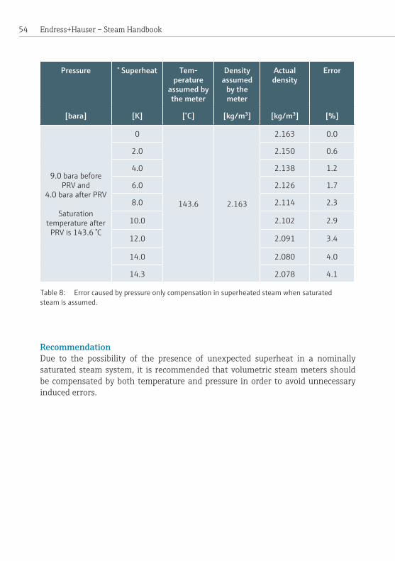
Endress+Hauser – Steam Handbook 54
Pressure ° Superheat Tem-perature
assumed by the meter
Density assumed
by the meter
Actual density
Error
[bara] [K] [°C] [kg/m³] [kg/m³] [%]
9.0 bara before PRV and
4.0 bara after PRV
Saturation temperature after
PRV is 143.6 °C
0
143.6 2.163
2.163 0.0
2.0 2.150 0.6
4.0 2.138 1.2
6.0 2.126 1.7
8.0 2.114 2.3
10.0 2.102 2.9
12.0 2.091 3.4
14.0 2.080 4.0
14.3 2.078 4.1
RecommendationDue to the possibility of the presence of unexpected superheat in a nominally saturated steam system, it is recommended that volumetric steam meters should be compensated by both temperature and pressure in order to avoid unnecessary inducederrors.
Table 8: Error caused by pressure only compensation in superheated steam when saturated steam is assumed.

55
Some hazards of steamSteamisextensivelyusedinmanydifferentindustriesbecauseitsproperties,fromaengineeringperspective,arehighlyadvantageous.However,thesesameproper-ties give rise to a number of hazards associated with steam; principally its expansive propertiesandelevatedtemperature.Inorderforsteamtobesafelyharnesseditisessentialthatengineersandplantoperatorshavesufficientunderstandingofthesehazards so that they can minimize the risks to themselves and others which natu-rallyarisewhensteamisused.Thefollowinggivesabriefdescriptionofanumberoftheprincipalhazardsassociatedwithsteam.
Boiling liquid expanding vapor explosion (BLEVE)Thisoccurswhenavesselcontainingasaturatedliquidatelevatedpressurefails.When the vessel fails, a fraction of the liquid is vaporized and rapidly expands giving risetothetermBLEVE.BLEVEsarenotrestrictedtosteam,however,onlysteamis under consideration here. Historically BLEVEs are associated principally with MTHSandwater-tubeboilers.ThereareseveraldifferentcausalpathsforaBLEVE to occur:
Some hazards of steam
Figure 15: Locomotive boiler explosion and its consequences. Source: Wikimedia Commons (https://commons.wikimedia.org/wiki/File:Boiler_explosion_1850.jpg)

Endress+Hauser – Steam Handbook 56
BLEVE due to overpressure only: Whilst possible, there are no recently documented examples in Western Europe of MTHS boilers failing purely due to overpressure (although they were relatively common in the nineteenth century) as this requires a complete failure of both the pressurecontrolsandthesafetyvalve.
BLEVE due to failure of the longitudinal seam weld at normal working pressure:There are several documented examples of BLEVE involving steam boilers which oc-curredatnormalworkingpressure.Intheseaccidentsthepressurevesselsweresig-nificantlyweakenedbycorrosionandthermalcyclingwhichcausedstresscorrosioncrackstoforminthelongitudinalseamweld.OncethecracksreachacriticalsizethepressureinsidetheboilercausesthewholeseamtofailresultinginaBLEVE.Note: thecatastrophicfailureofanyweldonapressurevesselcanresultinaBLEVE.Howeveritisthelongitudinalseamweldthatmorecommonlyfails.
BLEVE due to a low-water condition:This mode of failure is predicated by some failure of the level controls which causes the heating surfaces inside the boiler to become exposed to steam vapor whilst the furnaceisstillfired.Theheatingsurfacesthenstarttoheatup.Ifthemetaltem-peraturebecomestoohigh,thefurnacewallbecomesplasticandlosesitsstrength.Theexternalpressureonthefurnacethencausesittobuckleinwardsorcollapse.InextremecasesthefurnacedetachesfromanendplateresultinginaBLEVE.
BLEVE due to insulation of the heating surfaces:In this mode the heating surfaces are covered on the waterside with a layer of depo-sition.Thisisoftenduetohardscalecausedbypoorwatertreatmentalthoughothercontaminantscanhavethesameeffect.Thedepositioninsulatesthefurnacefromthewaterwhichwouldnormallycarry theheataway.Thisresults in thefurnaceoverheatingwiththesameresultsasaBLEVEduetoalow-watercondition.
Examples of BLEVE also occur in other sectors of industry and examples can be foundintheliteratureoronsocialmediasites.
Column collapse water hammerThis is considered particularly dangerous because it can occur when steam is not be-ingusedforprocess,i.e.when“nothing”isthoughttobehappening.Itrequiresthatadownstreamvalvebeclosedwhichcreatesaneffectivedead-leg in conjunctionwith a U-bend from which the condensate is not removed (Figure 16 showing initial condition).AsthecondensatecollectsitgraduallyfillsthebottomoftheU-bendandstartstoriseuptheverticallegs.

57
Valve open Valve closed14 barg 14 barg
Trap closed
Q
AtthispointapocketofstreamistrappeddownstreamoftheU-bendbutitismain-tained at pressure by continuity from the live steam upstream, through the conden-sate (Figure 17).Asthecondensaterisesuptheverticallegsitbecomesstratifiedand a temperature gradient forms with the condensate at the saturation tempera-tureatthefreesurfacesandthesub-coolingtosomeminimumatthelowestpoint.
Ifleftinthissituationforlongenoughwhich,dependingontheconditionsandlinesize, could take several days, the water level will rise up (Figure 18) until it starts to floodthehorizontallinesections.
Asitdoesso,thedownstreampocketofsteamwillcomeintocontactwithsub-cooledcondensateandwillstarttocondense.Thisreducesthesizeofthesteampocketanddraws more condensate up the line exposing the remaining steam to condensate
Some hazards of steam
Figure 16: Column close water hammer, starting condition.
Figure 17: Column closure water hammer, stratification and sub-cooling.
Valve open Valve closed14 barg 14 barg
Trap closed
Q

Endress+Hauser – Steam Handbook 58
whichhasbeensub-cooledtoagreaterdegree.Atsomepointtheremainingsteaminthepocketwillcondensealmostinstantaneouslycreatingapartialvacuum.Thecolumn of condensate will then be pushed into this void by the upstream pressure (Figure 19), until it is driven into the downstream valve at which point line rup-tureoccurs.ForadetailedexplanationofthecauseandconsequenceofanexampleofcolumnclosurewaterhammerthereaderisreferredtotheUKHealth&Safety Executive(HSE)reportintotheaccidentatBPGrangemouthin2000.
Figure 18: Column closure water hammer, flooding and steam pocket collapse.
Figure 19: Column closure water hammer, line rupture.
Valve open Valve closed14 barg 14 barg
Trap closed
Q
Valve open Valve closed14 barg14 barg
Trap closed
Q
Valve open Valveclosed
14 barg 14 barg
Trap closed
Q

59
Sub-cooled condensate induced water hammer There are a largenumber of different scenarios inwhich sub-cooled condensateinducedwaterhammercanbeinduced.Thefollowingtextillustratesjustafewpos-siblescenarios.Thistypeofhazardiscommonlyassociatedwithcoldstartsordistri-butionsystemsthatareoperatedintermittently.Forsub-cooledcondensateinducedwater hammer to occur it is necessary for there to be sub-cooled condensate in the distributionsystem,pooledorcollectedforsomereason.Whenlivesteamcomesinto contact with this sub-cooled condensate, it condenses, giving up its heat to the condensate.Ifthelivesteamisbroughtonquicklyithasatendencyto“jet”intothe
Some hazards of steam
Centric reducer
Vortex flowmeter
Condensate collection point
To control valve (DN 100)
DN 150 DN 100
Eccentric reducer
Manual control valve
DN 1
00
DN 150
Figure 20: Condensate collection due to trap failing closed.

Endress+Hauser – Steam Handbook 60
Figure 21: Condensate collection due to trap failing closed.
condensateand steambubblesbecome isolated.Because theyare surroundedbyrelatively cold condensate they collapse instantaneously with a popping or bang-ing sound. These collapses result in shockwaves travelling through the systemwhich are potentially very destructive – this form of water hammer can be likened to hitting the pipeworkwith a sledgehammer. This description above represents relativelyminorsub-cooledcondensate inducedwaterhammer. Inseverecasesaline rupture is quite possible and there a number of documented instances which haveresultedindeathorsevereinjury.
Figure 20 is a representative drawing of part of an actual system which was sub-jected to repeatedwater hammer, causing repeated failures of vortex flowmetersensors. The systemwas operated throughout the day until eight o’clock in theevening at which point an upstream control valve was closed and the downstream sectionof the lineallowed to cool.Atapproximately fouro’clock in themorningthis control valve was opened and live steam at approximately 8 barg entered the system.Lookingattheupperline,thepipedroppedverticallydownandcondensatecollected against the top of a closed control valve (Fig.20/1).Lookingatthelowerline, concentric joints had been used to increase the line size to DN 150 rather than eccentriconesasintheupperline.Thisagainallowedthecondensatetocollectwithnomeansofescape.
When the live steam came into contact with the sub-cooled condensate it “jetted” into it andwaterhammer resulted.The shockwaveswhich resultedwereof suf-

61
ficientmagnitude to cause failureof thevortexflowmeter sensorsona repeatedbasis.Thepipeworkwassubsequentlymodifiedtoremovethecondensatecollectionpoint.However,ifithadbeenleftlongenoughtherewouldhavebeenariskoflinerupture.
Figure 21 shows another way in which condensate can collect – through a trap whichhasfailedclosed.Thisisnotuncommonassteamisanaggressivemedium.However,theincidenceofwaterhammereventsisoftenexacerbatedbythefailureofenduserstochecktheirsteamtrapsonaregular,frequentbasis.
Flash steam explosion Althoughuncommon,flashsteamexplosionsstilloccur in steamboilersandcanalsobefoundinothersettings.Thesehappenwhenrelativelycoldliquidwaterhitsa veryhot surface. Indoing so, someof thewater is instantly vaporized to form superheated steam which expands very rapidly with an accompanying pressure wave.Ifthisoccursinsideapressurevesselsuchasasteamboiler,itcanresultincatastrophicfailure.
Anexampleof thiswasaboiler thathadadangerous low-watercondition–thelevel was low enough that the heating surfaces were exposed to steam vapor rath-erthanliquidwaterwhilsttheburnerwasstillfiring.Thissituationissometimescalled a “dry-fry”.Theboilerwas left longenough that themetalof the furnaceoverheated.Theoperatorwhofoundtheboilerinthisconditionmanuallyinjectedfeedwater into the boiler instead of shutting it down. This caused a flash steamexplosion of such magnitude that the pressure vessel ruptured and the boiler ex-ploded.Theboilerwasforcedsome30to35metersawayfromitsoriginalpositionanddebriswasspreadoveralargearea.
Overpressure in the distribution systemSteam is generated at a higher pressure than is necessary for the consumers to en-sure that there is enough pressure available when it reaches the point of require-ment.Toprovidecontrollabilitypressurereducingvalves(PRV)areemployednearto the consumers.Downstreamof the PRV safety valves are fitted as the down-streamequipmentmayberatedtoalowerpressurethantheboiler.IfboththePRVandsafetyvalvefailthereisariskofdownstreamfailureduetooverpressure.
Overpressure (inside a pressure vessel)See section “Boiling liquid expanding vapor explosion (BLEVE)” on Page 55.
Some hazards of steam

Endress+Hauser – Steam Handbook 62
Valve opened
Liquid water
Valve closed
Steam at pressure
Wave formation
Slug of water moving at the steam velocity
Impact at next valve or dead end
Trap
Figure 22: An example of plug flow water hammer.
Plugflowwater hammerThisphenomenoniscausedbyaslugofwaterwhichhasfilledthepipecrosssectionandispushedalongbythesteambehindit.Itcanquiteeasilycauselineruptureiftheslugimpactsonapipebend,forexample.

63
Forplugflowwaterhammertooccurcondensatemustbepresentinsufficientquan-tity inthesteamline.Thecondensatecanbeeithersaturatedorsub-cooled.Thepresenceofsufficientcondensateisfrequentlycausedbypoordesignorinadequatemaintenance exacerbated by inadequate fall in the lines, incorrect support, failed trapsandmissinginsulation.Aswithalltypesofwaterhammer,theprobabilityofitsoccurrenceissignificantlyincreasedifsteamisadmittedtoorapidlyintotheline.
AnexampleisshowninFigure 22:Anupstreamvalveisclosedanddownstreamofthevalvecondensatehascollected.Whenthevalveisopenedthesteamrushesdownthepipeandasitdoessoitstartstopushthecondensateaheadofit.Ifthereis enough condensate and the line is long enough, the amount of condensate being pushedalong increasesuntil it completelyfills thesteammain.At thispoint theslugofwateristravellingatthespeedofthesteamwhichcouldeasilybe110km/h(~70mph)ormore.Whentheslugreachestheriserrequiredforthesteamtrapitsmashes into it and if the slug possesses enough kinetic energy it will cause a line rupture.Theprobabilityoflineruptureisincreasedinolderandpoorlymaintainedsteamsystems.
Steam hammerThisisaphenomenonassociatedwiththerapidopeningorclosingofavalve.Con-sideralongsteamlinewhichcontainsavalvewhichcanberapidlyopenedorclosed.Let us suppose that the valve is open and that the bulk velocity of the steam is 30m/s(110km/hor~70mph)andthatthevalve issuddenlyclosed.However,thesteamstillpossessesmomentum.Upstreamofthevalvethismomentumcausesthe mass of steam to be driven onto the closed face of the valve causing a pressure spike.Whentheoverpressurehasreachedamaximum,thesteamreboundsoffthesurfaceofthevalveandeventuallyequilibriumisreached.
Downstream of the valve the momentum of the steam carries it away from the valve resultinginarapidlocalpressurereduction.Itisthecombinationofthelocaloverandunderpressuresthatconstitutesteamhammer.Steamhammernormallydoesnot result in a line rupture or valve failure unless combined with a further risk factor suchasbadlycorrodedlinesorcastironvalves.
TemperatureSteamatpressureisbyitsverynaturehot.Duetothehighthermalconductivityofthe associated steel work, its temperature approximates closely to that of the steam insidethepipeworkevenwhenuninsulatedandlocatedinadverseconditions.Thetemperatureof10barasaturatedsteamis179.9°Candtheexternaltemperatureof
Some hazards of steam

Endress+Hauser – Steam Handbook 64
itssteamlinewillbeapproximately175°C.Steelworkatthistemperaturewillveryeasilyburnhumanskin.Minimal,effectivelyinstantaneouscontactwillleaveskinwithalightburnorblistering.Contactforjustafewsecondswillverylikelycauseafullpenetrationburn–thetypethatrequiresaskingraft.
When opening up steam lines for manual work, the operator must not only ensure that there are suitable isolations in place but also that the temperature of the line has fallensufficiently–preferably touch temperature.Thereason for this is thateven though a line which has been isolated and a local pressure gauge shows zero, if the line is very hot some fraction of any residual condensate will re-boil at low pressure.Ifalineisquicklyisolatedandimmediatelybreached,i.e.stillhot,thereisariskofburnstotheindividual.
Note: The above is not adefinitivestatementconcerningtheopeningupofasteamline.Greatcaremustbeexercisedtoprovethecontentsofthelineandsufficiencyofisolationsbeforeworkisundertaken.
Vacuum drawThedensity of steam ismuch lower than liquidwater at the same temperature. Under certain circumstances this can lead to dangerous incidents:
Vessels which are steam-cleaned:Duringthisprocessmostoftheairinthevesselwillbeevacuatedbysteam.If,oncethe process is completed, the vessel is sealed shut the pressure inside the vessel will fallasthesteamcondenses.Thiswilleventuallyleadtoalargepressuredifferencebetween the inside of the vessel (at some sub-atmospheric pressure) and the out-sideatatmosphericpressure.Certainvesselswhicharedesignedtowithstandinter-nalpressure,suchasthinwalledliquidtankers,arenotabletowithstandsignificantexternalpressure.Thevesselmaythencollapseduetotheexternalpressure.
Vacuum draw into a boiler:Thisoccurswhenaboilerisallowedtocoolwiththecrownvalveleftopen.Italsore-quiresthatanon-returnvalveiseithernotfittedorisdefective.Astheboilercools,thedensityoftheliquidfractioninsidetheboilerincreases.Oncethetemperaturehasfallensufficientlyapartialvacuumoccurs.Thisthendrawssteambackthroughthemainintotheboiler.Ifsomeformofcontaminationhasenteredthesteammain,thiswillalsobedrawnintotheboiler.Inoneinstanceacidwasdrawnintotheboilerwhich caused corrosion leading to the boiler being condemned at its next inspec-tion.Inanotherincidentoxygenwasdrawnintotheboiler.Thiscontributedtotheeventualfailureoftheboilerandasubsequentexplosion.Inathirdincidentasteamboilerbecamefullyfloodedasdidthesteamlineimmediatelydownstreamofit.

65
WaterloggingThis is not in itself a hazard, however, when a sub-cooled waterlogged steam system iscombinedwithlivesteam,thencondensingwaterhammereventswilloccur. Itispossibleforasinglecondensingwaterhammereventtoresultinalinerupture.However, it is more common for the water hammer events to be of a smaller mag-nitude.Thesemaythencontribute,overtimetothefailureoflineequipmentinthevicinityofthewaterhammeroralinerupture.
Waterlogging may result from poor design in which condensate can collect in a lo-cationfromwhichitcannotberemovedduetothelackofasteamtrap.Incorrectrepairworkmayalsoresultinthissituationinanotherwisewelldesignedsystem.Trapswhichfailclosedorwhicharerenderednon-functionalduetoblockages.Poormaintenanceisanothercause.Note:Theabovetopicsarenotexhaustive.Poorormissinginsulationwillcontributetowaterloggingasthiswillgreatlyincreasetherateofcondensateformation.
Some hazards of steam
Figure 23: Destroyed factory building caused by a boiler explosion (Meuselwitz, Germany, 1904).

Endress+Hauser – Steam Handbook 66

67Boiler operation
Boiler operationModern steam boilers are automatic in operation and it is very important to un-derstandthisanditsimplicationsforbothoperatorsandmanagers.Theirrolesarebrieflydiscussedasistheroleoftechnologyandafewofthemoresignificantriskfactorswhichaffecttheirsafeoperation.
The boiler operatorThe role of the boiler operator has undergone marked change in recent years due to the ongoing trend to reduce the use of manpower in the boiler house and im-provementsintechnology.Onmanysites,theboilerhouseiseffectivelyunmannedon an hour-by-hour basis with the operator only coming in to perform checks as required, the frequency of which might be as little as once every three days on some sites.Furthermore,itshouldbenotedthattheoperatorsthemselvesareoftenless knowledgeableaboutboileroperationandsteamsystems.Formanyitisasecond-aryworkactivityandmoreoveronethatisoftenoutsidetheircorecompetencies.
Letussupposethatwearebringingamodernsteamboileronline.Ithasadequatewater inside it, theburner is switchedon, butnotfiringas it is at itsmaximum workingpressureandthecrownvalveisclosed.Oncethecrownvalveisopenedtheboiler will operate automatically without human intervention, and in theory could dosoindefinitely.Thisisbecausethesteamisdrawnfromtheboilersolelyduetothepressuredifferencebetween inside theboiler and in thedistribution system.Whensteamisdrawnoutoftheboilerthenitspressuredrops.Whenitfallstoapredeterminedsetpointtheburnerwillstartautomaticallyandwillkeepfiringuntilthe pressure increases to the maximum working pressure whereupon the burner willstopfiring.Theburnerwillnotfireagainuntilthepressureagaindropstothesetpoint.Duringnormaloperationthewaterlevelinsidetheboilerisalsoautomati-cally controlled and feedwater will be periodically pumped into the boiler, maintain-ingsufficientlevelrequiredforsafeoperation.Thissetofeventscould,intheory,goonindefinitelywithouthumaninterventiononcethecrownvalvehasbeenopeneduntilitisrequiredtobeclosed.Onemustthereforeaskthequestion:whatistheroleoftheoperatorintoday’sboilerhouse?
•Oversight:Amulti-tubularhorizontalshellboilerisastoreofenergywhenatpressureandthereisaneverpresentriskofcatastrophicfailure.Thereforethechecking and testing of controls and safety critical systems is of crucial importance.
• Response to alarms and troubleshooting: It is important that operators can respond to alarms in a timely manner and also to investigate and correctly

Endress+Hauser – Steam Handbook 68
identify their various causes in order to prevent the risk of a dangerous occurrencefromhappening.Itisthereforevitalthatoperatorsareappropriatelytrainedandcompetent.
•Operation:Thereisstillsomeoperationrequiredofsteamboilers.Oneexampleiscoldstartswhichmustbeperformedinaccordancewiththemanufacturer’sinstructionsandwhichalsomustbeperformedwithanoperatorinattendance.It should be noted that repeated cold starts which are incorrectly performed have contributedtoanumberofboilerfailures.
•Maintenance (preferably planned rather than reactive): Once maintenance has been performed, it is vital that safety systems are tested as a number of accidents have occurred because checks have not been performed following maintenanceworks.
• Record keeping: Records are very useful on a number of levels, for example wheresitesoperatemulti-shiftworkingtheoperatorsmaynotevenseeeachotheronaregularbasissothewrittenrecordsformthemainpointofcontact.Records can also demonstrate that the correct checks and tests have been performedthusreducingtheriskofregulatoryactionintheeventofanaccident.They are also necessary for risk analysis and can be very useful when troubleshooting.
The managerFollowing on from the changes to the role of the boiler operator, that of the man-agerhasalsochanged.Onmanysitestheboilerandsteamsystemcompriseonlypartofamanager’sresponsibilityandaswiththeoperator,inmanyinstancesspe-cificspecialistknowledgeofboilersmaywellnot formpartof theirprimarycorecompetencies.
In thefirst instanceaboilerhousemustcomplywith localandnational lawsandregulations.Thisisaprimaryduty.Secondlytheinstalledplantshouldbeoperatedinamannerwhichreducesriskasfarasisreasonablypracticable.(Thisstatementreflectstheglobaltrendtowardsgoal-basedregulationasopposedtoaprescriptiveapproach.)
Inachievingtheabovethemanagerneedstoensurethatsystemsofworkarefitforpurpose and also that manning levels of suitably trained and competent persons are adequate.Themanagermustthenenforceappropriateoversighttoensurethattheplantisoperatedasintendedandthatanyincidentsareappropriatelyinvestigated.The manager must also ensure that he or she has adequate knowledge so that their dutiesandobligationscanbeadequatelydischarged.

69Boiler operation
Asmanninglevelshavedecreased,therenaturallyfollowsthequestion:howmaytechnologybegainfullyemployedtopartiallyreplace/aidtheboileroperatorinthisparadigm?A fewexamplesaregiven in the textbelow.The introductionofnewtechnology should be given careful consideration to ensure that it is both appropri-ateandthatthebestuseismadeofit.
The role of technology in the modern boiler houseApartial answer is to understand the role that technology canplay in replacingandhelpingtheoperator.Withinthisframeitshouldbenotedthatconsiderationstowards safety – bearing in mind the potential consequences of catastrophic failure –shouldbegivenprimacyoverefficient,effectiveoperation.Fortunatelya“safer”boilerinstallationismorelikelytobeaneffective,efficientunit.
Consider Figure 24, a fault tree diagram based on actual boiler incidents which pos-tulates the question: what are the causal factors of a waterside explosion or furnace collapse foraMTHSboiler?Ascanbeseen, thereareanumberofdifferent fac-torsthatcancontributetoafailureandinsomeaccidentsseveralfactorscombine.Therefore reduction in the risk of a single factor in isolation will reduce the overall riskofafailure.Note:Itshouldnotbedeemedsufficienttomitigateriskfactorsonapartialoradhoc basis, they must be considered in toto although it may be necessary to examine eachoneindividually.
Let us now consider how and where technology may be usefully employed in miti-gating individual risk factors, helping the boiler operator and substituting for the operator.
Pressure cyclesThe pressure vessel of a steam boiler is constantly subjected to changing tempera-tureandexpandsandcontractsasthetemperaturerisesandfalls.Thissubjectsthevessel to fatigue.During the statutory inspection the inspectorwill estimate thenumber of full and partial pressures to which the vessel has been subjected and this willinfluencethepredictedlifeoftheboiler.Atpresentpressurecyclesarerarelyrecorded.However,doingsowouldpermittheinspectortomakeamoreaccuratecalculationregardingthepredictedlifeoftheboiler.Itwouldalsoallowtheuserofthe boiler to make informed decisions concerning the reduction of, in particular, full pressurecycles.
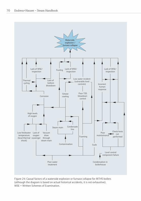
Endress+Hauser – Steam Handbook 70
Waterside explosion /
furnace collapse
Lack of WSE/inspection
Incorrect human
response
Check/testsnot
performed
Level controlcomponent failure
Condensation in boilerhouse
Scale
Poormaintainance
Low water incident(vulnerable level
controls)
Poor TDSblowdown
control
Foaming
Contamination
Condensateline
Steam main
Greasecoating
Lack of WSE/inspection
Fouling
Poor watertreatment
Low feedwatertemperature
(local thermalshock)
Lack ofoxygen
scavenger
Vacuumdraw
throughsteam main
High levelsof oxygen
Thermalcycling
Lack of WSE/inspection
Lack of bottom
blowdown
Corrosion
Figure 24: Causal factors of a waterside explosion or furnace collapse for MTHS boilers (although the diagram is based on actual historical accidents, it is not exhaustive). WSE = Written Schemes of Examination.

71
Over-firingduringcoldstartExcessivefiringduringcoldstartmeansthatthefurnaceisverymuchhotterthanthe restof thesteelwork that comprises theboiler’spressurevessel.Asa conse-quence the furnace thermally expands much more than the rest of the vessel, result-ing in a number of very undesirable consequences:
• Thevesselisstressedinwayswhichthedesignerdidnotintend.Thiswillcontributetoanunexpecteddegradationoftheboiler’santicipatedlifeduetoincreasedfatigue.
• Theboilerendplateswilltendtobowout.Inextremecasesthiscancausetubesintheconvectivepassestopartiallypulloutoftheendplateresultinginleaks.
• Cracksmayformatweldedligaments.• Itisacausalriskfactorforcatastrophicfailureofthepressurevessel.
Technologycanbeusedtoautomatethefiringsequenceofaboilertopreventexces-sivethermalstrain.Note: Thisdoesnotmeanthatacoldstartcanbeun-manned.Acoldstartmustalwaysbeattendedbyatrainedandcompetentindividual.
Selection of level controlsManyboilersintheUnitedKingdomarefittedwithlevelcontrolswhichcompriseamixtureofcapacitanceandconductivityprobes.Thesearefittedwithprotectiontubes,andingeneraltheyarereliableandworkwell.However,theyallrelyontheconductivity of the water inside the boiler to function correctly and there is a re-sidualriskinsituationswherefoamingoccurs.ThismaybeduetosomefailureoftheTDScontrollerorunwantedcontamination.
Alternativetypesofprobesuchasguidedradar,vibratingfork,positivedisplacementanddifferentialpressureareavailableatreasonablecost.Byemployinginstrumentswithdifferentprinciplesofoperation,diversityisbroughtintotheinstallationandriskposedbycertainknownandforeseeableeventsisreduced.Itshouldhoweverbenoted that all controls possess vulnerabilities and selection of appropriate controls shouldbemadeonasite-by-sitebasis.Note: Onsiteswhereverypurewater isusedtofeedtheboiler,e.g. fromreverseosmosisplants,therehavebeeninstanceswherethecapacitance/conductivitysys-temshavefailedtooperatecorrectlywhentheboilerisfirstfilledwithwaterasitsconductivityistoolow.
Overview of required tests and checksAlthoughoperators inmany instancesarenot required tobe in theboilerhouseat all times, they are required to undertake regular tests which comprise two main categories.Therearewhataretermeddailychecks,although–dependingonthe
Boiler operation

Endress+Hauser – Steam Handbook 72
equipmentfittedtotheboiler–itispossiblethatthefrequencyisreducedtoonceeverythreedays.Thereisalsotherequirementfore.g.anevaporationtesteveryweek. Anevaporation test is one where the water level inside the boiler is lowered to force alow-watereventtoconfirmthatthelimitersareworkingcorrectly.Itisveryimpor-tantthattestsarecompletedasrequired.Inthecaseoftheevaporationteststherehave been a number of catastrophic failures of boilers due to a primary failure of a safetycriticalsystemwhichwasnottestedasitshouldhavebeen.
Technology can be employed to electronically record that tests have been completed, when they are intended to have been performed and evidence this to both manage-mentandregulatorybodies.
The above is also important to prevent abuse of systems of work: there have been instancesofoperatorsfillingoutseveralmonthsworthofdailyandweeklyrecordsjustbeforeaninspectorisduetoundertakethestatutoryinspection.

73Steamboilerefficiency
Steam boiler efficiencyTherearetwomethodsofassessingthethermalefficiencyofasteamboiler:thefuel-to-steam(direct)methodandtheindirectmethod(seebelow).Theyarenotdirectlycomparable, although it may be possible to estimate one from the other under cer-taincircumstances.ThereareanumberofstandardswhichmaybeappliedtothesemethodsincludingBS845:1987,BSEN12953-11:2003andDIN4702-8.Themostcommon standard used in the United Kingdom is BS 845 although references to DIN 4702andBSEN12953-11arenotinfrequent.Aswithallcalculations,theuncer-taintywilldependupon the care takenwith themeasurementsandcalculations.Efficienciesdeterminedusingdifferentstandardsshouldnotbedirectlycomparedastheyusedifferentmethodologiesandreferencequantities.ForexampleBS845-1uses15°CasthereferencetemperaturewhereasEN12953-11uses25°C.Efficien-cies should be quotedon either a gross calorific (GCVorHHV)or anet calorific (NCV or LHV)basisalthoughitisnotuncommontoseenetefficienciesquotedwhicharegreaterthan100%whereinagrossbasishasbeencomparedtoanetbasis.
Steamboilermanufacturerswillnormallyonlyquoteindirectefficienciesasthesearesolelyderivedfromtheboilerwhereasfuel-to-steamefficienciesaresitedepen-dantwithlocalfactorssuchaswaterqualityandblowdownrateshavingsignificanteffects.Manufacturersallusedifferentcalculationbases,e.g.fuelcarbon/hydrogen(CH)ratioandcalorificvaluestogeneratequotedefficiencies.Thiscanmakeitdif-ficultfortheusertocompareoneboileragainstanother.
Consideringfire-tubeboilers,thecombustionefficiencyisdeterminedbytheburnerandfurnacecombinationwhilsttheoverallthermalefficiencyisdeterminedbythedesign as this governs the exit temperature of the gases from the boiler for a given firing rate and boiler pressure.A number of configurations have been tried, theUnited Kingdom market settling on the three-pass wetback to provide the optimum balancebetweenrunningcosts,physicalsize,complexityandcapitalcost.RecentinnovationsinEurope,SouthernAfricaandNorthAmericahaverenewedinterestinenhancedheattransfertechniques,andboilerswithimprovedthermalefficienciesarestartingtoappearonthemarket.
The following refers to BS 845 although the basic principles are the same for the othermethods.
Indirect method ThisiscoveredinBS845-1:1987andisreferredtoastheconciseprocedure.Theindirect method is suitable for all fuel types under steady state conditions and may

Endress+Hauser – Steam Handbook 74
bedefinedas“Thedeterminationofthermalperformancebytheassessmentofthethermallossesandthemeasuredthermalinputoroutput”.Thecalculationdeter-minesthevariousheatlossesfromtheboilerintheformofpercentages.Thesearethensubtractedfrom100togivethecalculatedindirectefficiency.BS845-1statesatolerancefortheresultsof±2%forthermodynamicallysimpleboilers.ItshouldbenotedthatalthoughboilermanufacturerswillquoteaBS845-1efficiencyforboilersfittedwitheconomizers,thesedonotstrictlyfallwithinthedefinitionof“thermo-dynamicallysimple”.ThecalculationsarestatedinsectionsixofBS845-1andthelosses may be summarized as follows:
• Lossduetosensibleheatinthedryfluegas• Lossesduetoenthalpyinthewatervaporinthefluegases• Lossduetounburntgasesinthefluegases• Loss due to combustible matter in ash and riddlings• Loss due to combustible matter in grit and dust• Radiation, convection and conduction losses
It should be noted that the calculation of the heat input used in BS 845 may be manipulatedtorenderitindependentoftime.Thisformsthebasisofcombustionanalyserswhichprovideinstantaneousefficiencies.Onlycleanburningliquidandgaseousfuelsshouldbeassessedonaninstantaneousbasis.Testsundertakenstrict-ly in accordance with the standard should last for a minimum of one hour during which time steady state conditions are maintained and six sets of results obtained inthattimeframe.
The inputs and variables required by the BS 845-1 calculations are:
•Mass of fuel supplied over the duration of the test•Duration of the test (This may be eliminated for instantaneous calculations)•Grossornetcalorificvalueofthefuel• Carbon/Hydrogen(CH)ratioofthefuel• Loss due to radiation, convection and conduction • Temperature of the combustion air entering the burner• Carbon dioxide content of the exhaust gases (percentage, dry volumetric basis).Oxygencontent,wetordrybasismaybesubstitutedwithsuitablemodificationstothecalculations.
• Temperature of the exhaust gases•Moisturecontentofthefuelasfired(considerednegligibleincoldor
temperate climates)• Carbon monoxide content of the exhaust gases (percentage, dry volumetric
basis)

75Steamboilerefficiency
•Quantityofashesandriddlingspertonneoffuelburnt/hour(drybasis)•Quantityofdustandgritpertonneoffuelburnt/hour(drybasis)• Carbon content per tonne of fuel burnt of ashes and riddlings (dry basis)•Carboncontentpertonneoffuelburntofgritanddust(drybasis). (Thesearenotrequired/negligibleforliquidandgaseousfuelsunder conditionsofgoodcombustion.)
Typicalpeakefficienciesforstandardnaturalgasandlightoil-firedMTHSboilerswithout enhancements are around 80 and 83% respectively when correctly com-missioned; themaindifferencebeingdue to thediffering carbon/hydrogen (CH)ratiosofthetwofuels.ThelossesofMTHSsteamboilersarethusaround17to20%ofwhichthefluegaslossesarebyfarthemostsignificant,accountingforover90%ofthelosses.
Recent innovations in enhanced heat transfer techniques applied to the convective passeshaveenabledthermalefficienciestobeincreasedbyupto2.5%throughex-haustgastemperaturereductionalthoughthesizeoftheboiler,firingrateandfueltypewillhaveasignificantimpactonthefinalimprovementinefficiency.
There ishoweveran inherent limit to improvements inboiler efficiency imposedbythesaturationtemperatureofthesteamwherethepressurevesselisdefinedasthesystemboundary.Thesteaminsideaboilerrunningat10.3barg,forexample,hasasaturationtemperatureof184.1°C,andastheexhaustgastemperatureap-proachesthisvalue,theeffectivenessoftheheattransferwithinthepressurevesselprogressivelyreduces.Moreover,itisnotpossiblefortheexhaustgasestobelowerintemperaturethanthatoftheheatcarrier.
Therefore, further efficiency gains are best considered external to the pressure vessel.Thecommonestexampleofthisistheeconomizer,agastoliquidheatex-changer used to pre-heat the incoming feedwater by cooling the exhaust gases.These are often sized to reduce the exhaust gas temperature by a further 80 to 100 °C, simultaneously increasing the feedwater temperature by 25 to 30 °C, result-inginanefficiencygainof4to5%.Analternativeistousetheexhaustgasestopre-heattheincomingcombustionair.
Oftheremainingvariablesonlythecarbondioxide/oxygencontentoftheexhaustgasescanbedirectlyaltered(viamodificationof theburnersettings).Fortypicalcarbondioxideconcentrations,8to12%,a1%changewillaffecttheboilerefficiency byaround0.65to0.75%.Thiscanalsobeseenasachangeinexhausttemperaturedue to the change inmassflow rateof theexhaustgases foragivenamountof fuelburn.

Endress+Hauser – Steam Handbook 76
For a given burner setting the exhaust temperature, as previously stated, is de-terminedbytheeffectivenessoftheconvectivepasses.Foulingofthepasseswillcause the exhaust temperature to rise and thus the thermal efficiency to fall. Foulingmay occur on either the gas or thewater side of the convective passes.Foulingon the gas side isnormally due to poor combustion andhas little effectotherthantoreducethethermalefficiencyoftheboiler.Ontheotherhandwater-side fouling is normally caused by a build up of scale on the internal heat transfer surfaces.Ifthescaleformsathickenoughlayeroverthefurnace,itcanleadtoa collapseof the furnace.Gas side foulingmayoccuroveravery short time framewhereas waterside fouling often takes several months.Whilst the result of the fouling is the same (an increased exit temperature of the exhaust gases) analysis of therateofchangeofthistemperaturemayindicatethecausalmechanism.
Shelllossesareverydifficulttomeasurepreciselyandthesimplestmethodistolookupestimates,e.g.theappropriatetableinBS845-1.Thetablesstatetheshelllossesasapercentageof thefuelfiringrateatmaximumcontinuousrating(MCR).Forfiringratesbelowthis,theshelllossesmustbefactoredappropriately.Forexamplea boiler rated at less than 2 MW is assumed to have a rate of heat loss of 1% of the heatinputatfullfire.Athalfload,whiletherateofheatlossisthesamewhencon-sideredine.g.kilowatts,thepercentageheatlossisdoubledto2%asitisafunctionoftherateofheatinputtotheboiler.Note:Ifthemassofwaterinsidetheboilerisknown,theunfiredstandinglossescanbe estimated by measuring the boiler pressure twice over a one hour interval and calculatingtherefrom.
If a modern burner is attached to the boiler and is well set up, the concentration of carbon monoxide in the exhaust gases would be expected at less than 20 ppm andmayconsequentlybeignored.Burnersaresetuptoprovidetheoptimumbalance between air-fuel ratio and emissions particularly carbon monoxide and oxides of nitrogen.Athighfiringratesexcessairlevlsof15%areconsistentlyachievableinconjunction with low carbon monoxide (CO) and nitrogen oxid (NOx)levels.Atlowfiringrates,however,excessairlevelstendtobearound30%duetopotentialprob-lemswithflamestability.
Theeffectofvariablechangesonthermalefficiencyare:
Exhaust temperature: 1% per 20 °C change in temperatureAmbienttemperature: 1%per20°CchangeintemperatureExcessair: 0.5%per6%change
(Values are approximate and dependent on fuel type and interaction with other variables.)
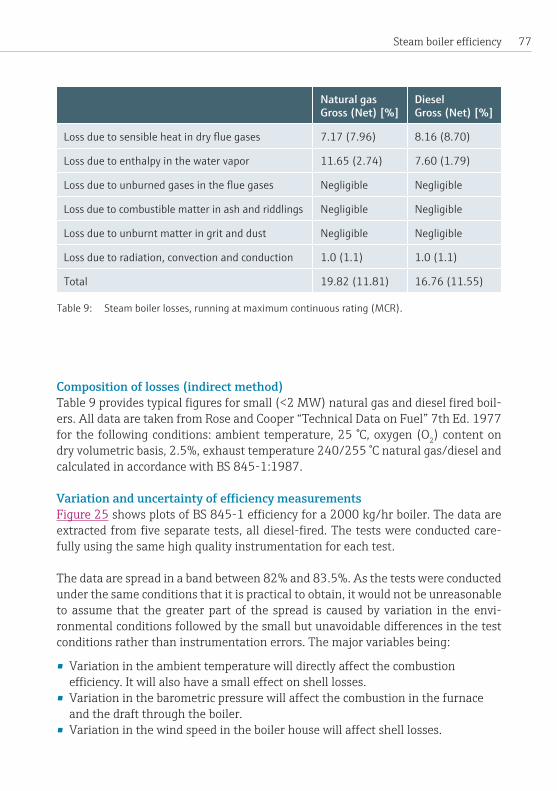
77Steamboilerefficiency
Natural gasGross (Net) [%]
DieselGross (Net) [%]
Loss due to sensible heat in dry flue gases 7.17 (7.96) 8.16 (8.70)
Loss due to enthalpy in the water vapor 11.65 (2.74) 7.60 (1.79)
Loss due to unburned gases in the flue gases Negligible Negligible
Loss due to combustible matter in ash and riddlings Negligible Negligible
Loss due to unburnt matter in grit and dust Negligible Negligible
Loss due to radiation, convection and conduction 1.0 (1.1) 1.0 (1.1)
Total 19.82 (11.81) 16.76 (11.55)
Composition of losses (indirect method)Table9providestypicalfiguresforsmall(<2MW)naturalgasanddieselfiredboil-ers.AlldataaretakenfromRoseandCooper“TechnicalDataonFuel”7thEd.1977for the following conditions: ambient temperature, 25 °C, oxygen (O2) content on dryvolumetricbasis,2.5%,exhausttemperature240/255°Cnaturalgas/dieselandcalculatedinaccordancewithBS845-1:1987.
VariationanduncertaintyofefficiencymeasurementsFigure 25showsplotsofBS845-1efficiencyfora2000kg/hrboiler.Thedataareextractedfromfiveseparatetests,alldiesel-fired.Thetestswereconductedcare-fullyusingthesamehighqualityinstrumentationforeachtest.
Thedataarespreadinabandbetween82%and83.5%.Asthetestswereconductedunder the same conditions that it is practical to obtain, it would not be unreasonable to assume that the greater part of the spread is caused by variation in the envi-ronmentalconditionsfollowedbythesmallbutunavoidabledifferencesinthetestconditionsratherthaninstrumentationerrors.Themajorvariablesbeing:
•Variationintheambienttemperaturewilldirectlyaffectthecombustionefficiency.Itwillalsohaveasmalleffectonshelllosses.
•Variationinthebarometricpressurewillaffectthecombustioninthefurnaceandthedraftthroughtheboiler.
•Variationinthewindspeedintheboilerhousewillaffectshelllosses.
Table 9: Steam boiler losses, running at maximum continuous rating (MCR).

Endress+Hauser – Steam Handbook 78
BS84
5-1:
1987
Gro
ss e
fficie
ncy
[%]
80
81
82
83
84
85
0 10 20 30 40 50
Time [minutes]
• It is almost impossible to maintain a constant shell pressure and thus shell temperaturebothduringandbetweentests.Evenminorvariationsintheshelltemperaturewillaffecttherateofconvectiveheattransferinthetubebanks.
• Theburnerusedpossessedmechanicallinkagesusedtocontrolthedamper. Thiswillvarythemassflowratethroughtheboiler.
Aleadingindependentassessorofindustrialboilersstatesthatthemostaccuratetestthattheyhaveachievedis±1.8%,undercarefullycontrolledconditions.Whenconsidering an individual test there are a number of potential sources of instrumen-tationerrors.Errorsmayresultfromtwomainsources:inaccuracyoftheinstrumentitselfandpoorexperimentaltechnique.
Exhaust gas temperature measurement error Measurementofanaccuratebulkexhausttemperatureisdifficult.Inorderforthisto be done with a minimum of uncertainty, cross duct measurements of both lo-caltemperatureandlocalvelocityarerequired.Aninvestigationofa6MWMTHSboiler revealed a cross duct temperature variation of approximately 50 °C, equating to2.5%uncertaintyinindirectefficiency.
Figure 25: Efficiency measurement according to BS 845-1:1987.

79Steamboilerefficiency
Observational comparison of dial-type thermometers compared to 3-mm-diameter Endress+HauserK-typeinsulatedthermocouplesindicateatemperaturedifferenceofbetweenfiveandtendegreescentigrade;thedial-typethermometergivingthelowerreading.Radiationlossesmayalsobesignificant.Note: Some boiler makers do not insulate all of their rear smoke boxes, mainly for reasonsofeconomy,howeveritdoeshavetheeffectofartificiallysuppressingtheexit temperatureandthus increasingthe indicatedefficiency,asdemonstrated inthefollowingexample.Theerror,solelyduetoradiation,istheequivalentofover0.5%ofthecalculatedthermalefficiency.
Example: Suppose the exhaust gas temperature in theboilerflue ismeasuredat240 °C and that theflue is uninsulated andhas an internalwall temperature of 75 °C. Then, the temperature loss due to radiationmaybe calculatedas follows, usingtypicalvaluesforemissivityandheattransfercoefficient:
δT = measurement error (K)Tm = measured temperature (513 K)Ts = radiation surrounding temperature (348 K)σ = Stefan Boltzmann Constant (8.559 × 10⁻⁸ W/m2 K4)ε = emissivity (0.2)h = heat transfer coefficient (50 W/m2 K)
Thus radiation losses coupled with a less accurate indicator may easily contribute an errorapproaching1%.
Exhaust gas composition errorOne of the more accurate and common methods of determining the gas composition is the use of a zirconia probe which indicates the percentage (wet basis) of oxygen intheexhaustgases.Ifcalibratedcorrectlytheyareconsideredtohaveanaccuracywithin5%ofreading.Thiswouldtranslateintoanerroroftheorder0.1%whenfac-toredintothethermalefficiency.However,calibrationintervalsareoftenextendedandthuszero,andspandriftmaygiverisetomuchmoresignificanterrors.Errorswhichaffectthewatercontentoftheexhaustgaseswillhaveadisproportionateef-fectontheoverallthermalefficiencyerrorduetothelatentheatofthewater.
Shell lossesBecause of the sheer size and complexity of many boiler installations, accurate de-terminationofshelllossesisverydifficult.Therateofheatlosswillbesignificantly
( )

Endress+Hauser – Steam Handbook 80
greaterwhentheboilerisrunningbutthisinturnwillbeaffectedbytheshelltem-perature.Theprevailingatmosphericconditionsmayalsohaveasignificanteffect.For this reason shell losses are generally taken from the reference tables of BS 845-1AppendixB.Themostcommonerrorwhenconsideringshelllosses,whethermea-suredorreferenced,isfailuretofactorthemforthefiringrate.
ItshouldalsobenotedthatAppendixBmakesnoallowanceforpossibledifferencesofshelltemperature.Forexample,an18bargboilerwillhaveashelltemperatureofupto209.8 °Cwhilsta6bargboilerwouldhaveamaximumof165.0 °Cwithconsequentlylowerradiation,conductionandconvectionlosses.
Fuel composition and calorificvalueIngeneralthecalorificvalueofthefuelistakenfromutilitybillsorprovidedbythesupplier.ForliquidfuelstheCH(carbon/hydrogen)ratiomayberequestedalthoughitusuallyhastobeinferredfornaturalgas.Thisisusuallydoneonaninfrequentbasis,andthusvariation in the fuelqualitywillnotbeknown.Achangeof±1%inthehydrogenratiovaluewillresultinachangeincalculatedefficiencyof0.5to0.75%dependingonfueltype.Asimilarvariationinthecarbonratiovalueaffectsthecalculatedefficiencybylessthan0.2%.
Thethermophysicalpropertyvariationofthefuelmayalsohaveasmallbutsignifi-canteffectonerrors,especially inthe instancewherethefuel ispre-heated(e.g.heavy fuel oil) by up to 60 °C from the reference temperature but is not accounted forinthecalculations.
Direct or fuel-to-steam efficiencyThis aspect is covered in BS 845-2:1987 and is referred to as the comprehensive procedure.Initssimplestform,asdeterminedinthemajorityofboilerinstallations,it merely consists of the measured energy output of the steam divided by the energy inputderivedfromaknowledgeofthefuelanditsflowrate.
m = mass flow rate (kg/s)h = enthalpy (J/kg)δH = enthalpy of combustion (J/kg)
( ) ( )

81
Effic
ienc
y [%
]
Time
Cumulative efficiencyHourly efficiency
5 minute efficiency
20
40
60
80
100
120
140
Steam consumption over period: 46 240 kg
07:00 08:40 10:20 12:00 13:40 15:20 17:00 18:40 20:20 22:00 23:40
Steamboilerefficiency
It is important to note that many processes require the heat content of the steam andnotthesteamitself.Thusformanyinstallationsaccurateknowledgeofthisisasimportantasknowledgeofthesteamquality.
Thefuel-to-steamefficiencyisnotsuitableforinstantaneousorshort-timeperiodmeasurements.Thisisduetothefactthattheenergyinputratedoesnotnecessar-ilymatch theenergyoutput rate.Theburneralways follows thedemand.This isespeciallytrueofstoredenergyunitssuchasfire-tubeboilerswhicharecapableofdelivering a large amount of steam at constantly reducing pressure – even when the burnerisnotfiring.Figure 26plotsactualfuel-to-steamefficienciesoverbothfive
Figure 26: Fuel-to-steam efficiencies with varying time spans.

Endress+Hauser – Steam Handbook 82
0
20
40
60
0 20 40 60
Gross energy input [GJ]
Cumulative efficiency: 97.2%
Hea
t exp
orte
d in
stea
m [G
J]minute and one hour intervals and compares it to the same data used to calculate acumulativeefficiency.Thefiveminutedataisspreadovernearlythewholerangeoftheverticalaxis,i.e.0to140%andismeaningless.Thedatapointsinexcessof100%willcoincidewithperiodswhensteamisflowingbuttheburnerisnotfiringwhile the data points with very low values will correspond to periods when steam flow isvery lowbut theburner isfiring inorder to restorepressure. It shouldbenotedthatgas-firedburnersmaytakeseveralminutestogothroughthestart-upcycle.Ifthesteamdemandishighduringthisperiod,theefficiencywillbevastlyoverstated.
The hourly interval data is also meaningless as the lag between the demand and thefiringisstilltoogreat.Thisresultsinthewidevariationandoverstatementofefficiency.Thecumulativeefficiencyhowever,isofmuchmorevalue.Thedatausedto create Figure 26wascollectedatfiveminuteintervals.Usingthecumulativeap-proach, the variation caused by the burner lag is of little importance and a more realisticindicationofefficiencyisprovided.
Datashouldalwaysbeconsideredinthecontextofthesitefromwhichitwastaken.Inthisinstance,theboilerwassometenyearsold,naturalgas-firedandwithoutaneconomizer.Fromaknowledgeoftheexpectedefficiencydeterminedbytheindirect
Figure 27: Unrealistic cumulative efficiency data.

83Steamboilerefficiency
method,thefuel-to-steamefficiencywouldbeexpectedtobenomorethanabout77%,assumingidealconditionsandhighqualityfeedwater.However,theefficiencyofthisunitisindicatedataround80%.Figure 27showsthecumulativeefficiencyofthesameboiler,thedataacquiredonadifferentdayofthesameweek.Overthisday,thecumulativeefficiencyis97%.Thisinitselfisclearlyimpossible,andismore-overmarkedlydifferenttothe80%ofFigure 26.
Consideringfirstthediscrepancybetweenthetwoefficiencies,thepossiblecauseswouldeitherberelatedtotheboilerortothemetering.Inordertoachieveavaria-tion of this magnitude, the boiler operating characteristics would have to change by anamountsolargeastobecompletelyunrealistic.Thisthenleavesconsiderationofthemetering.Itwas,infact,foundthattherewerenumerousproblemswithboththesteamandgasmeterswhichrenderedthedatavalueless.
It should be noted, however, that the company from which this data was taken accepteditwithoutquestion.This is a common problem: there is a lack of under-standing of metering, its installation and interpretation of the data.
For many companies trending information is more important than absolute accu-racy.Thusmeasurement,ifaccurate,ofjustthesteamandfuelisadequateforthispurpose.TherequirementofBS845-2todeterminetheboundariesofthesystemandaccuratelymeasurewithinthemisunnecessary.Whenanalysingdata,manycompaniesareconcernedwiththeirfuelcostsratherthanthesteamdatainitself.Theyconvertandrestatethedataonanenergyandthenfinancialbasis.Thisisasourceoferrormorecommonthanonewouldsuspect.
The thermophysical properties of steam can change markedly as it passes through itsdistributionsystem.Somecompaniesdonotactuallyknowwhattheoptimumsteamqualityfortheirparticularpurposeis.Figure 28 presents data for an indus-trial process, the steam being supplied by fire-tube boilers. The demand profile,instantaneousandwithvery largefluctuations representsaworst caseoperatingscenarioforthistypeofboiler.Ascanbeseentheinstantaneouspeakdemandoftenexceedstheboilerratedcapacity.Thiswasaresultofinstallingextraprocessequip-mentwithoutregardtothesupplysystem.Thesteamsuppliedaftertheproductionincrease was extremely wet, and carryover was a major problem to the extent that the water quality inside the boilers was uncontrollable; the boiler also frequently lockedoutduetoprimingevents.Thishadtheeffectofincreasingproductiontimeswithmajorcostimplicationsforthecompany.Note: It isoftenthecasethatthedownstreamcostimplicationsaremuchgreaterthantheoperatingcostsoftheboiler.Gainsfromimprovingadistributionsystemcanfaroutweighgainsfromimprovementsintheboilerhouse.
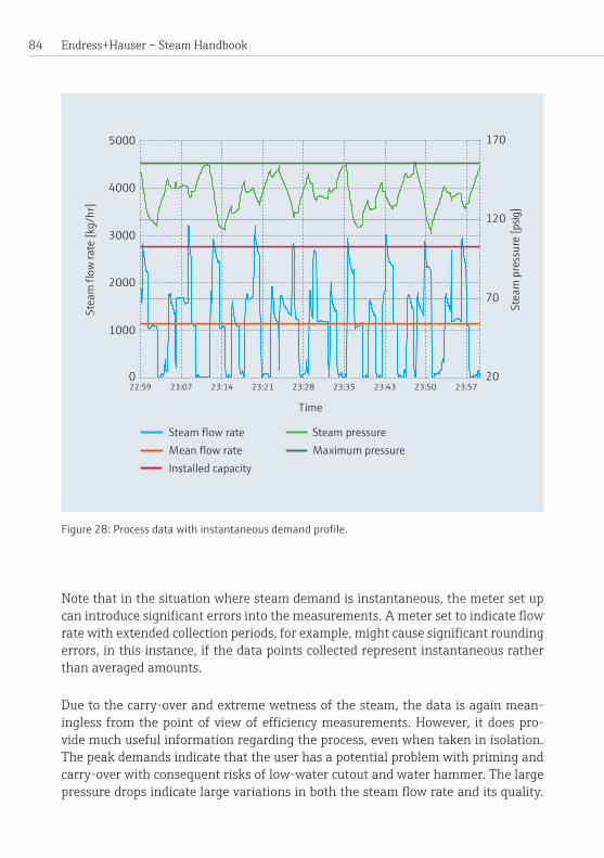
Endress+Hauser – Steam Handbook 84
Note that in the situation where steam demand is instantaneous, the meter set up canintroducesignificanterrorsintothemeasurements.Ametersettoindicateflowratewithextendedcollectionperiods,forexample,mightcausesignificantroundingerrors, in this instance, if the data points collected represent instantaneous rather thanaveragedamounts.
Due to the carry-over and extreme wetness of the steam, the data is again mean-ingless fromthepointofviewofefficiencymeasurements.However, itdoespro-videmuchusefulinformationregardingtheprocess,evenwhentakeninisolation.The peak demands indicate that the user has a potential problem with priming and carry-overwithconsequentrisksoflow-watercutoutandwaterhammer.Thelargepressuredropsindicatelargevariationsinboththesteamflowrateanditsquality.
Figure 28: Process data with instantaneous demand profile.
0
1000
2000
3000
4000
5000
22:59 23:07 23:14 23:21 23:28 23:35 23:43 23:50 23:57
Time
Stea
m fl
ow ra
te [k
g/hr
]
20
70
120
170
Stea
m p
ress
ure
[psig
]
Maximum pressureSteam pressureSteam flow rate
Mean flow rateInstalled capacity

85Steamboilerefficiency
The data also shows that the boiler is being cyclically thermally stressed which – if combined with other causal factors – could be (and indeed has been) the cause of a dangerousincident.
Manyusersdonotappreciateandthereforefailtousedatagatheredforefficiencypurposesformonitoringwithregardtooperationalsafety.Intheabovecase,forex-ample, it would be very simple to link the pressure transmitter to an alarm or control pointtogiveanadditional,remotewarning/controlofboilerpressure.

Endress+Hauser – Steam Handbook 86
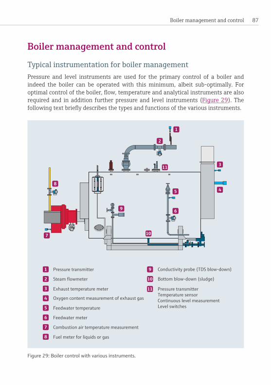
87Boiler management and control
Boiler management and control
Typical instrumentation for boiler managementPressure and level instruments are used for the primary control of a boiler and indeed the boiler can be operated with thisminimum, albeit sub-optimally. For optimalcontroloftheboiler,flow,temperatureandanalyticalinstrumentsarealsorequired and in addition further pressure and level instruments (Figure 29).Thefollowingtextbrieflydescribesthetypesandfunctionsofthevariousinstruments.
Figure 29: Boiler control with various instruments.
Bottom blow-down (sludge)
Conductivity probe (TDS blow-down)
Oxygen content measurement of exhaust gas
Steam flowmeter
Exhaust temperature meter
Pressure transmitter
Feedwater temperature
Feedwater meter
Combustion air temperature measurement
Fuel meter for liquids or gas
Pressure transmitterTemperature sensorContinuous level measurementLevel switches
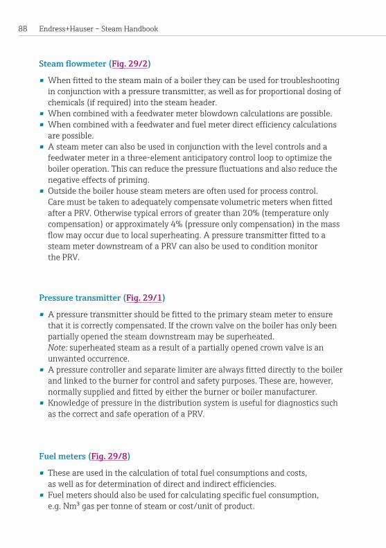
Endress+Hauser – Steam Handbook 88
Steam flowmeter(Fig. 29/2)
•Whenfittedtothesteammainofaboilertheycanbeusedfortroubleshootingin conjunction with a pressure transmitter, as well as for proportional dosing of chemicals(ifrequired)intothesteamheader.
•Whencombinedwithafeedwatermeterblowdowncalculationsarepossible.•Whencombinedwithafeedwaterandfuelmeterdirectefficiencycalculationsarepossible.
•Asteammetercanalsobeusedinconjunctionwiththelevelcontrolsandafeedwater meter in a three-element anticipatory control loop to optimize the boileroperation.Thiscanreducethepressurefluctuationsandalsoreducethenegativeeffectsofpriming.
•Outsidetheboilerhousesteammetersareoftenusedforprocesscontrol. CaremustbetakentoadequatelycompensatevolumetricmeterswhenfittedafteraPRV.Otherwisetypicalerrorsofgreaterthan20%(temperatureonlycompensation) or approximately 4% (pressure only compensation) in the mass flowmayoccurduetolocalsuperheating.Apressuretransmitterfittedtoasteam meter downstream of a PRV can also be used to condition monitor thePRV.
Pressure transmitter (Fig. 29/1)
•Apressuretransmittershouldbefittedtotheprimarysteammetertoensurethatitiscorrectlycompensated.Ifthecrownvalveontheboilerhasonlybeenpartiallyopenedthesteamdownstreammaybesuperheated. Note: superheated steam as a result of a partially opened crown valve is an unwantedoccurrence.
•Apressurecontrollerandseparatelimiterarealwaysfitteddirectlytotheboilerandlinkedtotheburnerforcontrolandsafetypurposes.Theseare,however,normallysuppliedandfittedbyeithertheburnerorboilermanufacturer.
• Knowledge of pressure in the distribution system is useful for diagnostics such asthecorrectandsafeoperationofaPRV.
Fuel meters (Fig. 29/8)
• These are used in the calculation of total fuel consumptions and costs, aswellasfordeterminationofdirectandindirectefficiencies.
• Fuelmetersshouldalsobeusedforcalculatingspecificfuelconsumption, e.g.Nm³gaspertonneofsteamorcost/unitofproduct.
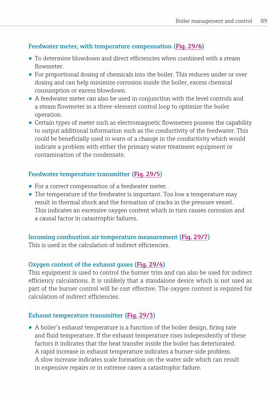
89Boiler management and control
Feedwater meter, with temperature compensation (Fig. 29/6)
• Todetermineblowdownanddirectefficiencieswhencombinedwithasteamflowmeter.
• Forproportionaldosingofchemicalsintotheboiler.Thisreducesunderoroverdosing and can help minimize corrosion inside the boiler, excess chemical consumptionorexcessblowdown.
•Afeedwatermetercanalsobeusedinconjunctionwiththelevelcontrolsand asteamflowmeterinathree-elementcontrollooptooptimizetheboileroperation.
• Certaintypesofmetersuchaselectromagneticflowmeterspossessthecapabilitytooutputadditionalinformationsuchastheconductivityofthefeedwater.Thiscouldbebeneficiallyusedtowarnofachangeintheconductivitywhichwouldindicate a problem with either the primary water treatment equipment or contaminationofthecondensate.
Feedwater temperature transmitter (Fig. 29/5)
• Foracorrectcompensationofafeedwatermeter.• Thetemperatureofthefeedwaterisimportant.Toolowatemperaturemayresultinthermalshockandtheformationofcracksinthepressurevessel. This indicates an excessive oxygen content which in turn causes corrosion and acausalfactorincatastrophicfailures.
Incoming combustion air temperature measurement (Fig. 29/7)Thisisusedinthecalculationofindirectefficiencies.
Oxygen content of the exhaust gases (Fig. 29/4)This equipment is used to control the burner trim and can also be used for indirect efficiencycalculations.Itisunlikelythatastandalonedevicewhichisnotusedaspartoftheburnercontrolwillbecosteffective.Theoxygencontentisrequiredforcalculationofindirectefficiencies.
Exhaust temperature transmitter (Fig. 29/3)
•Aboiler’sexhausttemperatureisafunctionoftheboilerdesign,firingrate andfluidtemperature.Iftheexhausttemperaturerisesindependentlyofthesefactorsitindicatesthattheheattransferinsidetheboilerhasdeteriorated. Arapidincreaseinexhausttemperatureindicatesaburner-sideproblem. Aslowincreaseindicatesscaleformationonthewatersidewhichcanresult inexpensiverepairsorinextremecasesacatastrophicfailure.

Endress+Hauser – Steam Handbook 90
•Ameasurementoftheexhausttemperatureisalsorequiredforthecalculationofindirectefficiencies.A20°Cchangeinexhausttemperatureapproximatestoa1%changeintheindirectefficiencyoftheboiler.
Contamination of condensateThisissitespecific,dependantontheprocessesforwhichthesteamisbeingused.Contamination of condensate can cause foaming, carry-over, internal damage and catastrophicfailureofaboiler.Thisshouldbediscussedwiththeenduserandap-propriatemonitoringequipmentfittedaswellasameansofdisposingofunwantedcontaminated condensate. Common measurements on condensate lines includeconductivity,turbidityandpH.
Boiler level controlsManyboilersinEuropearefittedwithlevelcontrols(Fig.29/11) which comprise a capacitanceprobeforpumpcontrolandacapacitanceand/oraconductivityprobeforthelimitingdevices.Thesearefittedwithprotectiontubes,andingeneraltheyarereliableandworkwell.However,theyallrelyontheconductivityofthewaterinside the boiler to function correctly and there is a residual risk in situations where foamingoccurs.Thismaybeduetosomefailureofthetotaldissolvedsolids(TDS)controllerorunwantedcontamination.
Alternative typesofprobesuchasguided radar,vibrating fork,positivedisplace-mentanddifferentialpressureareavailableat reasonablecost.Byemploying in-strumentswithdifferentprinciplesofoperation,technologicaldiversityisbroughtinto the installation and the risk posed by certain known and foreseeable events is reduced. It shouldhoweverbenoted thatall controlspossessvulnerabilities,andselection of appropriate controls should be made on a site-by-site basis with respect to(inter)nationalstandardsandnorms.Note: Onsiteswhereverypurewater isusedtofeedtheboiler,e.g. fromreverseosmosis plants, there have been instances where the capacitance or conductivity meteringsystemshavefailedtooperatecorrectlywhentheboilerisfirstfilledwithwaterasitsconductivityistoolow.
Hotwell temperatureThehotwellisastoreofwaterforsupplytotheboiler.Itshouldbemaintainedatahigh temperature to minimize thermal shock and the oxygen content of the feedwa-ter.Itstemperatureshouldbemeasuredandcomparedtothefeedwatertempera-tureasadiscrepancymay indicateaproblemwith thehotwell.The temperaturemeasurementmayalsobeusedtocontrolanysteaminjectiontothehotwell.

91Boiler management and control
Hotwell levelAhotwellisusuallysizedtoholdenoughwaterfortheboiler(s)itsuppliesforthemtosteamatmaximumforcingrateforanhour.Automaticlevelmonitoringpermitsanorderlyshutdownintheeventofsomeupstreamfailure.
Total dissolved solids (TDS)Thefeedwatertotheboilercontainsbothimpuritiesandchemicals.However,thesteam exported is relatively pure water, consequently the impurities become con-centratedinsidetheboiler.Iftheconcentrationofdissolvedsolidsistoohigh,foam-ingwilloccur.Excessivefoamingcancausecarry-over of solids into the distribution system, or in severe cases result in a failure of certain type of level controls as de-scribedearlier.TheTDSoftheboileriscontrolledbymeasuringit(Fig.29/9) and blowingdowntheboilerifitistoohigh.ThisreducestheTDSinsidetheboilertoanallowablelevel.TDSblowdownsystemsarefrequentlysoldaspackageswithallthenecessarycontrollers,valveandthesensorcontainedwithin.
Alongwiththedissolvedsolids,waterwhichhasbeenheateduptothesaturationpressure(andthereforehasahighheatcontent)isalsoremovedfromtheboiler.ItisimportanttocontroltheTDSeffectivelyinordertominimizeblowdownratesandthecostofblowdown.

Endress+Hauser – Steam Handbook 92

93The European boiler market
The European boiler marketThe European market is fragmented along the following historical lines: national borders,designcodes,regulatoryframeworks,economicspheresof influenceandlanguage. The UK forms one of these fragments.With the advancement of the European Union (EU) and its process of harmonization, some of these divisions arebeingreduced,e.g.thepartialreplacementofnationaldesigncodeswithpan- European versions.However, they are still significant andwill remain so for theforeseeablefuture.
The UK market, in common with the rest of Europe, is very risk averse and conser-vative.MTHSboilersofthecurrent,packagedformhavebeenmanufacturedsincethe1930’sandcantracetheir lineagedirectlybacktoTrevithick’sCornishboiler of the early nineteenth century. The numerous catastrophic boiler failures lead-ing up to the modern age has resulted in a very safety-conscious, highly regulated industry.Thisnaturallyresultsinaslowdevelopmentprocessandaresistancetochange.
Improvementstothedesignofthepressurepartsofboilersoverthelasttwenty-fiveyears have been driven by improvements to the design codes with respect to safety andreliability rather than increases in thermalefficiency.Themajoradvances inthermalefficiencyduringthistimehavebeenmainlyduetotheburnermanufac-turers with innovations such as fuel-air mapping and servo-controlled, fully modu-lating dampers. Improvements to the internal heat transfer and thus to thermalefficiencieshavebeenminimalovertheperiod.Currentindustrynormsarearound80%fornaturalgasand83%fordiesel,indirectthermalefficiencies.
Environmental concerns and the large rises in fuel costs over the last decade, have ledtoavastlyincreasedinterestinthemarketforhigherfuelefficiency.Thesetwoissueshaveledsomemanufacturersindifferentpartsoftheworldtoindependent-ly pursue methods of increasing the amount of heat transferred in the convective passesofMTHSboilersthusimprovingefficiency.Typicalgainsareoftheorderof1to2%,additionaltothefiguresstatedabove.Althoughthisisarelativelysmallamount, it is a very useful increase when the fuel consumption rates of large heavily usedsteamboilersareconsidered,e.g.a10MW(net)steamboilerburnsaroundonetonneoffueloilperhouratfull load.Furtherworkiscurrentlybeingunder-takenaround theworld to improveboiler efficiencyand reduce the emissionsofundesirablepollutants.Inordertomaximizegainshowever,therewillneedtobeagreater emphasis on boiler control with attendant increases in metering and moni-toringwhichwillbediscussedinmoredetaillateron.

Endress+Hauser – Steam Handbook 94
Regulatory structure
ThefollowingremarksrelateindetailtotheUnitedKingdom.Thatsaid,theregu-lation of steam boilers worldwide generally follows the following principles: The boilers are manufactured to a recognized standard with external oversight during themanufacturingprocess.Onceinstalledandoperationaltheboilersareinspect-ed internally, usually on an annual basis coupled with a more in depth inspection requiringnon-destructive testing at set intervals, oftenfive to ten year intervals depending on the jurisdiction. The manning requirements for boiler operation are also regulated on a prescriptive or goal based approach depending on the juris-diction.
Design and construction approvals, and permits to operate in the UK are regulated by the insurance industry with guidance from relevant government departments andstatutorybodies.ThisisquiteunlikeinmostofcontinentalEurope,whereap-proval for the construction and use of steam boilers is obtained through government agenciesorotherstatutorybodies.
The system for design approval operated by the insurance industry is predicated on activeauthorization forallaspectsofpressurepartsandsystems.Nocomponentmay be introduced into a pressure vessel without approval, not only of the compo-nent,butalsoofthesystemcontainingthatcomponent.Thisalsoappliestoretro-spectivealterationsandrepairs.
AllsteamboilersmanufacturedintheEUmustconformtothePressure Equipment Directive(PED).Thisisageneraldirectivecoveringallpressureequipmentandisalegalrequirement.ThereareadditionallydesigncodesspecificallyforMTHSboilerssuch as the national UK standard PD 2790 and the pan-European EN12953.
AlthoughPD2790,EN12953orotherdesigncodesarenotlegalrequirementsinthe UK, they are to some practical extent mandatory as the insurance industry will not issue approvals unless conformance to a known standard has been satisfactorily demonstrated.
PD 2790 and EN 12953 are prescriptive standards relating to the structural integrity ofthepressurevesselpartoftheshell.Theyarenotperformancestandardsanddonotstateanyminimumefficienciestobeachieved.Theapproachofthesestandardsisbasedonexplicitstatementofapproval,e.g.specifiedgradesofmaterialforuseinthevaryingpartsoftheshell.Thishasresultedintheanomaloussituationofboilertube still being manufactured in accordance with BS 3059:1990, even though that standard is withdrawn and replaced by BSEN10217-1:2002.This isbecausePD
95The European boiler market
2790 explicitly permits the use of BS 3059, whereas BS EN 10217-1:2002 would requireaformalderogationfromtheinspectionbody.
Theuseofalternativematerialgrades,e.g.forboilertubes,ispermittedbyPD2790,however the manufacturer must satisfy the inspecting authority that the material willmatchorexceedtheperformancerequirementsofboththespecifiedtubestan-dard(BS3059)andtheshellconstructionstandard.Theprocessofdemonstratingconformity of an alternative grade is both lengthy and costly as numerous additional testsoveranextendedperiodoftimemayberequired.Inpracticethismeansthatvery few alternative materials have been adopted or used by UK manufacturers in boilershells.
It shouldbenoted thatapprovalby the inspectionauthority isexpensive.Designapprovalwilltypicallycostintheregionof£1000perboiler.Eachindividualboilermustbeindividuallyapproved;classapprovalisnotanoption.Anydesignchangetoanexistingshelldesignmustalsobeapprovedatextracosttothemanufacturer.Even minor changes to a shell such as the repositioning of a stabbing are classed as designchangesrequiringapproval.Thepressurepartsarealsophysicallyinspectedduringproduction,alsoatthecostofthemanufacturer.
Market structureThe retail market for MTHS boilers (<20 MW) in the UK is estimated at a stable 300 to400unitsperyearwithatotalpopulationof5000to10,000units.Themarketisthoughttobestatic,slowlyincreasingforsmallerboilers(<2MW).Abovethissizethepictureisoneofgentledecline.ThemajorcauseofthisistheongoingshiftofthemanufacturingbaseoutoftheUnitedKingdom,althoughthemarketisdifficulttoassesspreciselyasindustry-widefiguresdonotexist.
The market is considered to be strong in certain areas, for example: food and bever-age manufacturing, pharmaceuticals and “state” contracts such as Private Finance Initiate(PFI)fundedhospitalmodernizationprograms.Therecentvolatilityinfuelcostswhilsthavinglittleapparentaffectonoverallsalesvolumeshaveresultedinamovetohigherspecificationandmoreefficientequipment.
Figure 30 presents the conservatively estimated MTHS boiler market by thermal outputfor2007.Totalsalesareestimatedat300+units,thebalancebeingmadeupmainlybyverticalshellboilers,generallylessthan2MWcapacity.Themarketabove 8 MW net thermal output is very variable in the context of the small num-berssoldduetothefewsitesoperatingboilersofthisoutput.Additionally,whilstthethermaloutputrange0.15to2MWcoverssevendifferentmodelsofboilerby

Endress+Hauser – Steam Handbook 96
output,therangebetween8and10MWincludesonlytwo.Itshouldalsobenotedthatboiler salesdonotexactly reflect thesizedistributionof the installedboilerpopulation for the following reasons:
• The downsizing of installed plant due to reduced steam requirements is a long establishedtrend.
• The stronger market sectors generally require small or mid-range boilers (2to6MW).
• Largeunitsareoftenbeingreplacedbypairsofmid-rangeboilerscaused byapolicyshiftbyuserstopreferpairsofsmallerboilersratherthanasingle, largeone.
The United Kingdom boiler population includes a large number of very old boilers withmore than20yearsofoperation.Whilstanumberof thesearemaintainedforstandbypurposes,manyarestillusedastheprimesteamgenerator.Theseareinvariably less efficient thanmodern boilers fittedwith the latest energy savingequipment.Additionally,many are also oversized for the current steamdemandandwillalsosufferfrompoorqualityandhaphazardsteamdistributionsystems–aconsequenceofchangingrequirementsoverthelonglifeoftheboiler.Therefore,thereismuchscopeforreducingthefuelandothercostsformanyboileroperators.
0
50
100
150
200
0.15 to 2 2 to 4 4 to 6 6 to 8 8 to 10
Boiler net thermal output [MW]
Per a
nnum
sal
es
Figure 30: Estimated MTHS boiler market in the United Kingdom for 2007.

97The European boiler market
When considering steam boiler costs, a lifetime cost approach should always be used.HowevertheUnitedKingdommarketisverysensitivetothecapitalcostas-pect,oftentothedetrimentofthelifetimecost.Figure 31 shows the capital cost ofhigh specification boilers compared to the per annum fuel cost. The light-usecurverepresentsastandardcostillustrationthatmaybepresentedtoacustomer.The intensive use represents the maximum possible fuel cost of operating the boiler forayear.Althoughitwouldbeveryunusualtofindan installationoperatingatmaximumcapacity24/7,manyintensiveinstallationswilloperateatasignificantfractionofthis.Itshouldbenotedthattheseillustrationsdonotincludeothercon-sumablecostssuchaswater,electricityandchemicalswhichwillhaveasignificanteffectontheoveralloperatingcostandmayeasilyexceedthecapital costof theboilerinayear.
The fuel to capital cost per annum multiple ranges from 2 to 11 for the small boilers and5to25forlargerunits.Whenconsideredoverthestandard20yearlifetimeillustration of a boiler the capital cost represents around 1% of the lifetime fuel cost (withoutcompensatingforinflation).
Althoughthereareasmallandgrowingnumberofoperatorswhounderstandthebenefitsofoptimisingtheproductlifetimecoststherearestilltoomanywhofocus
Figure 31: Fuel versus capital costs of industrial boilers.
Cost
[£m
]
5 7 1031
Heavy use (av. 60% load 24/7/50) Light use (av. 60% load 8/5/50)Approx. capital cost (2007)
0
0.2
0.4
0.6
0.8
1
1.2
1.4
2 4 6 8 9
Fuel cost = £0.025/kWh
Thermal output [MW]
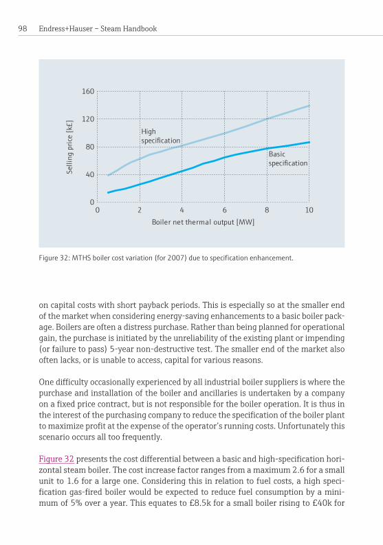
Endress+Hauser – Steam Handbook 98
oncapitalcostswithshortpaybackperiods.Thisisespeciallysoatthesmallerendof the market when considering energy-saving enhancements to a basic boiler pack-age.Boilersareoftenadistresspurchase.Ratherthanbeingplannedforoperationalgain, the purchase is initiated by the unreliability of the existing plant or impending (orfailuretopass)5-yearnon-destructivetest.Thesmallerendofthemarketalsooftenlacks,orisunabletoaccess,capitalforvariousreasons.
Onedifficultyoccasionallyexperiencedbyallindustrialboilersuppliersiswherethepurchase and installation of the boiler and ancillaries is undertaken by a company onafixedpricecontract,butisnotresponsiblefortheboileroperation.Itisthusintheinterestofthepurchasingcompanytoreducethespecificationoftheboilerplanttomaximizeprofitattheexpenseoftheoperator’srunningcosts.Unfortunatelythisscenariooccursalltoofrequently.
Figure 32presentsthecostdifferentialbetweenabasicandhigh-specificationhori-zontalsteamboiler.Thecostincreasefactorrangesfromamaximum2.6forasmallunitto1.6foralargeone.Consideringthisinrelationtofuelcosts,ahighspeci-ficationgas-firedboilerwouldbeexpectedtoreducefuelconsumptionbyamini-mumof5%overayear.Thisequatesto£8.5kforasmallboilerrisingto£40kfor
Figure 32: MTHS boiler cost variation (for 2007) due to specification enhancement.
Boiler net thermal output [MW]
0
40
80
120
160
0 2 4 6 8 10
Selli
ng p
rice
[k£]
Highspecification
Basicspecification
99The European boiler market
alargeboileroveroneyear’soperationbasedonthelight-usepatternpresentedin Figure 32.Thepaybackofthehighspecificationpackageincrementwouldthusbe36monthsforasmallboilerfallingto15monthsforalargeunit.
The5%efficiencygainrepresentsaminimum,takingtheoperatingprofileintoac-count,thismayeasilyincreaseto10orevenmore.Asanexampleofhowthisisachieved,theheatfluxtoatmosphereduringapurgecycleisinexcessof4.5%ofthemaximumcontinuousratingnetthermalinputtotheboiler.Thisequatestoareduc-tioninfuelconsumptionofabout1%iffivepurgecyclesperhourareeliminatedbythe use of a modulating instead of a hi-lo burner – not unreasonable at low load conditions.Again,thisanalysisissimplisticasitignoresincidentalsavingsduetoreducedelectricityconsumption(ifavariablespeeddriveisfitted),andthepoten-tialdownstreamprocess.Benefitsofahigheraveragesteampressureandimprovedboilerresponsetovariabledemand.
Anotherwayoflookingattheboilercapitalcostisbythecostperkilogrammeofsteam.Thistendstodecreasewithincreasingthermaloutputaslargerboilersareoftenoperatedmoreintensively.Itisthuseasiertojustifytheextracapitalrequiredtopurchaseenergysavingdevicesforalargeboilerthanasmallone.
AnumberofcompaniessupplyboilersintotheUKmarket.Thesemayberankedin order of estimated market share: indigenous manufacturers (these may also sell boilers imported from their overseas manufacturing operations), foreign manufac-turers with UK operations and importers – mainly from the continent, but also from otherpartsoftheworld.
The UK market itself may be sub-divided into the following categories:
1) PrivateFinanceInitiative(PFI)contracts:Essentiallygovernmentcontracts forhospitalsandotherfacilities.Thesearefrequentlyverypricesensitiveandthuslowmargin.
2) Intensiveindustrialuserswithaninstalledcapacityusuallyhigherthan 3MWwhoalmostalwayspurchasethethree-passwetbacktype.
3) Smallindustrialuserswhotraditionallyfavorthereverseflameandverticaltypes.
4) Other,e.g.museumsreverseoperatingsteamengines.
Verysmallhorizontalboilersareonlyavailable in thereverseflameformas it isnotpossible tomanufacture three-passwetbackboilersdue tospace restrictions.Thethree-passwetbackandreverseflamerangesoverlapinthenetthermalinput
Endress+Hauser – Steam Handbook 100
rangefrom0.8to3.3MW.Oneconsequenceoftherecentlargeincreasesinfuelprices has been that the three-pass wetback has taken market share from the re-verseflametypeduetoitsinherentgreaterefficiency.
One increasing trend, albeit of very small numbers, is purchase of containerized boilerhouses.Theseofferseveralbenefitstothecustomer:reducedon-siteinstalla-tiontimes,minimizationofplantdisruption,“allnew”boilerinstallationsofferingmaximumefficiencygains, theability tomove theboilerhousequicklyandwithminimumdisruptionaswellasincreasedresidualvalues.Theyareoftenfavoredfornewinstallationsorwhereacompletenewboilerhouseisrequired.Containerizedboilerhousesarealsobeneficialtothesupplierinthattheymaximizetherevenueearnedwhilstagainminimisingon-sitetimeandcost. Installationisasignificant–ifsitespecific–costofboilerplant,andistheareamostopentounforeseenormiscalculatedcosts.Itisnotuncommonforthetotalpackagecosttobedoubleoreventreblethecostoftheboileritself.

101Appendix
Appendix
Nomenclature
Allunitsareasindicatedunlessstatedotherwiseinthetext.
Symbol Meaning SI unitA cross-sectionalarea m2
a dimensionless constant
C dimensionless constant
Cƒ friction factor (4f)
cp specificheatcapacity J/kgK
CSA cross-sectionalarea m2
d diameter m
δp differentialpressure N/m2
δTLM logmeantemperaturedifference K
ƒ friction factor
g gravitationalconstant m/s2
G gasmassvelocity kg/sm2
GCV grosscalorificvalue J/Nm3
h specificenthalpy J/kg
H enthalpy J
k thermalconductivity W/mK
KE kinetic energy J
l length m
m mass kg
massflowrate kg/s
M molarmass kg/kmol
NCV netcalorificvalue J/Nm3
Q heat transfer J
Q heat transfer rate W .
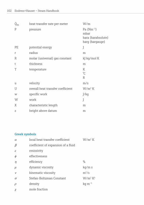
Endress+Hauser – Steam Handbook 102
Qm heattransferratepermeter W/m
P pressure Pa (Nm–2) mbar bara (barabsolute) barg (bargauge)
PE potential energy J
r radius m
R molar(universal)gasconstant kJkg/molK
t thickness m
T temperature K °C R
u velocity m/s
U overallheattransfercoefficient W/m2 K
w specificwork J/kg
W work J
X characteristic length m
z height above datum m
Greek symbolsα localheattransfercoefficient W/m2 K
β coefficientofexpansionofafluid
ε emissivity
φ effectiveness
η efficiency %
µ dynamicviscosity kg/ms
ν kinematic viscosity m2/s
σ Stefan-BoltzmanConstant W/m2 K4
ρ density kg m–3
χ mole fraction
.
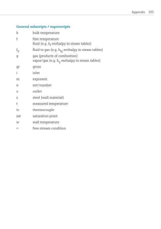
103Appendix
General subscripts / superscriptsb bulk temperature
f filmtemperature fluid(e.g.hf enthalpy in steam tables)
fg fluidtogas(e.g.hfg enthalpy in steam tables)
g gas (products of combustion) vapor/gas(e.g.hg enthalpy in steam tables)
gr gross
i inlet
m exponent
n net/number
o outlet
s steel (wall material)
t measured temperature
tc thermocouple
sat saturation point
w wall temperature
∞ freestreamcondition

Endress+Hauser – Steam Handbook 104
Dimensionless numbersDimensionlessnumbersareusedextensivelyinmanyareasofengineering.Theyareratiosofphysicalquantities.Theycanbeusedinvariousways,forexampletheycanprovideinformationregardingthepropertiesofthesystemunderquestion.Certaindimensionless groups can be related to each other empirically and used as design tools.
Grashof Number (Gr)
β coefficientofexpansionofafluid g gravitational constant ρ density d diameter ∆T temperaturedifference(betweenthe surfaceandthebulkofafluidbetweenlocal and ambient temperature) µ dynamic viscosity
TheGrashofnumberistheratioofbuoyancyforcestoviscousforces.Itisusedforsystemsinvolvingnaturalconvection.Itisfrequentlyusedincalculationsforheattransfer.
Nusselt Number (Nu) α localheattransfercoefficient d diameter k thermal conductivity
TheNusseltnumberisusedinheattransfer.Itistheratioofheattransferbyconvec-tionandconductiontoconductiononly.Itcanberelatedempirically,forexample,totheReynoldsandPrandtlnumbers(Nu=fn[Re,Pr])forforcedconvection,ortotheRayleighandPrandtlnumbers(Nu=fn[Ra,Pr])fornaturalconvection.
Prandtl Number (Pr) cp localheattransfercoefficient µ dynamic viscosity k thermal conductivity
( )
( )
( )

105Appendix
ThePrandtlnumberistheratiooftheratesofmolecularmomentumdiffusivitytothermaldiffusion.Itisrelatedonlytothethermophysicalpropertiesofthefluidinquestion.Itgivesinformationonthemechanismbywhichheatisdiffusedthroughafluid.
Reynolds Number (Re)
ρ density d diameter u velocity µ dynamic viscosity
TheReynoldsnumber is the ratio of inertia to viscous forces. It is used inmanyaspectsoffluidmechanicsandheattransfer.Itgivesinformationontheflowchar-acteristic,forexampleiftheReynoldsnumberofamovingfluidislessthan2000–thentheflowissaidtobelaminar(smooth).
List of abbreviationsASME AmericanSocietyofMechanicalEngineersBS British StandardBLEVE Boiling liquid expanding vapor explosionCIP Cleaning in placeEN European Standard (Norm)GCV GrosscalorificvalueHHV Higher heating valueLHV Lower heating valueMCR Maximum continuous ratingMTHS Multi-tubular horizontal steam (boiler)NCV NetcalorificvaluePED Pressure Equipment DirectivePRV Pressure reducing valvePD Published DocumentRO Reverse osmosisTDS Total dissolved solidsWSE Written Schemes of Examination
( )
Endress+Hauser – Steam Handbook 106
GlossaryAbsolute pressure:Pressuremeasurementwhosedatumisaperfectvacuum.Seealso gauge pressure.
Adiabatic process: The adiabatic process occurs without the transfer of heat across thesystemboundary.Theadiabaticflametemperature, forexample, is thattem-peraturewhichwouldbereachedbytheflameiftherewasnoheatlosstothesur-roundings.
Blowdown pit: Ablowdownpitconsistsofacoveredpitpartiallyfilledwithwaterwhich performs the same function as a blowdown vessel.Theyaremorecommonlyfoundinolderboilerhousesasblowdownvesselsarenowpreferred.
Blowdown vessel: Water which is blowdown from a boiler in the form of dissolved solids (see: TDS), blowdown or bottom blowdown is at elevated pressure and tem-perature. Both the temperature and pressure have to be dissipated safely beforethe blowdown can be safely disposed of. This is done in a blowdown vessel, i.e.apressurevesselpartiallyfilledwithwaterandpossessinga largevent toatmo-sphere.Whentheblowdownentersthevesselsomesteamisflashedoffandventedtoatmosphere.Theremaindermixeswiththecoldwaterandisdischargedtodrain.Ifblowdownratesareveryhigh,theflashsteammaybecollectedandreused.Blow-downvesselsareratedforpressureandarematchedtotheboilerhouseforcapacity.Analternativetoablowdownvesselisablowdownpit.
Boiler horsepower (American): Ameasureoftheusefuloutputofasteamboiler. 1boilerhorsepowerisequivalenttothegenerationof15.6kgsteamfromandat100°Cinonehour(9.8kW).
Bottom blowdown: Asa steamboiler exports steam, it concentrates solids con-tainedinthefeedwater.Someoftheconcentratedsolidssinktothebottomoftheboiler. If allowed tobuildup theywould interferewith itsnormal operationandmayposeahazard.Theyarenormallyremovedonadailybasisbyopeningavalvelocatedatthebottomoftheboiler.Thepressureinsidetheboilerthenforcesthesolidsoutalongwithaquantityofboilerwater.Theblowdownisnormallysenttoa blowdown vessel.
Carryover: Droplets of liquid water, foam or solid particles are drawn up with the steamvaporintothedistributionsystem.
107Appendix
Cavitation: Afluidclosetooratitssaturationtemperaturemaycontainbubblesofvapor.Thesefrequentlycollapseoftheirownaccord.Thetermforcollapsingbub-blesis“cavitation”.Cavitationissometimesobservedonthepressuresideofafeedpumpinboilerhouses.Ifthefeedwaterishotenoughandthereisnotenoughhead,the water will be close to its saturation temperature and steam bubbles will be pres-ent.Asthewaterpassesthroughthepump,itmovesfromthelowpressuresidetothehighpressureside.Duetotheincreaseinpressure,thewaterisnowunsaturatedandthesteambubblescollapseinstantaneouslycreatingshockwaves.Theseshockwavesarecapableofcausingsignificantdamagetothepump.
Condensate: Condensate forms inside the steam mains due to heat loss through thepipewalls.Itisremovedatfrequentintervalsusingsteam traps to prevent water hammerandmaintainthequalityofthesteam.Indirectprocessesonlyutilizethelatentheatofthesteamsoallthesteamcondensesbacktotheliquidphase.Con-densateisnormallyreturnedtotheboilerhouseforreuse.Insomesystemshoweverthecondensateisnotrecycled.Thisisfrequentlyduetounavoidablecontaminationmakingthecondensateunsuitableforreuse.
Critical point: The point at which the liquid, vapor and gaseous phases of a sub-stance are in thermodynamic equilibrium. Forwater this occurs at a pressure of221.2baraandatemperatureof374.15°C(647.30K).
Crown valve: The main valve attached to a boiler through which steam passes throughtothedistributionsystem.Itderivesitsnamefromitslocationonthetop,orcrown,oftheboiler.
Deadleg: A steam linewhich is connected to the distribution system andmain-tainedatpressurebutwhichnolongerservesanyconsumer.
Degrees of superheat:Superheatedsteamiscommonlydefinedintermsofitspres-sureanddegreesofsuperheat.Thedegreesofsuperheatisthetemperaturediffer-ence between the actual temperature of the steam and the saturation temperature atthesteampressure.Thussuperheatedsteamat10baraandafinaltemperatureof199.9 °Cwouldpossess20degreesof superheat. (Thesaturation temperaturebeing179.9°C).
Desuperheater: Apieceofequipmentusedtoreducethetemperatureofsuperheat-edsteamtoitssaturationtemperatureforthepressureatwhichitexists.CommonexamplesaresmallturbinesandVenturiwaterinjection.
Directefficiency: The ratio of useful heat exported from the boiler to the net or gross heat input. Comprehensive efficiency calculationsmay include the electri-
Endress+Hauser – Steam Handbook 108
cal energy consumption as well as the fuel consumption; sub-systems may also be accountedfor.
Dry fry: Theperiodduringalow-waterevent/conditionwhentheburnerisstillfir-ingandthemetalofthefurnaceexposedtosteamratherthanwater.Thiscausesanunwantedandpotentiallyhazardousriseinthemetaltemperature.
Dryback furnace:Afurnaceinwhichthe reversal cell is sealed using a refractory plug.Nousefulheattransfertotheheat carriertakesplacethroughtherefractory.
Dryness fraction: The fraction of wet steam which, if separated out, would consist ofsteamvaporonly.Awetsteammixturecomprising95%bymasssteamvaporand5%bymassofsaturatedliquidwouldhaveadrynessfractionof0.95.
Dry saturated steam: see Saturated steam.
Economizer: Aheatexchangerusedtorecoverwasteheatfromtheexhaustgasesofaboilerandtransferthatheatintothefeedwater.
Enthalpy:Atermfortheenergyofasubstance.Theenthalpyofasubstanceismadeup of the addition of its internal energy and the energy it possesses by virtue of its pressureandspecificvolumehencethedistinctnameforit.Enthalpycannotbedi-rectly measured, however the change in enthalpy can be determined if the change inpropertiessuchaspressureandvolumeareknown.Enthalpyisreferencedtoanarbitrarypoint.Forwaterthisisthetriple pointat0.01°C(273.16K)and0.006112bara.
Entropy: Ameasureofthedisorderofasystem.Asworkisperformedtheentropyofasystemtendstoincrease.
Fire-tube boiler:Aboiler inwhich the furnaceandheat transfer tubesare sub-mergedbythewaterbeingboiled.Theexhaustgasespassthroughtheboilerinsidethe furnace and subsequent heat transfer surfaces, usually banks of tubes known as convectivepasses.Thefurnaceandheattransfersurfacesaresurroundedbyashellofsufficientstrengthtowithstandtheinternalpressure–alsoknownas“smoke-tube” boilers, boilers multi-tubularhorizontalsteamboilers(MTHS).
Flashsteam(firsttype): Steam which is generated as a result of liquid water com-ing into contact with a surface which is hotter than the saturation temperature of thewater.Ifthetemperatureofthehotsurfaceisgreatenough,aflashsteamexplo-sionmayresult.

109Appendix
Flash steam (second type): Steam which is generated as a result of a pressure re-duction.Liquidwaterathighpressurehasagreaterenthalpythanwateratalowerpressure.Ifasaturatedliquidatelevatedpressureissuddenlyreducedinpressure,thedifferenceinenthalpyisgivenupbytheliquidcausingasmallfractionoftheliquidtoboiloffformingflashsteam.
From and at 100 °C (F&A 100 °C): Ameasureoftheusefulheatoutputofasteamboiler – equivalent to the enthalpy of the change of phase of water at 100 °C and 1.013 bara. This measure is normally expressed in kg/hr. 1 kg/hr from and at 100°Cequatesto0.627kW.
Gauge pressure: Pressurewhichisreferencedtoatmosphericpressure(i.e.0barg=atmosphericpressureatthetimeofmeasurement).Gaugepressureisthemostcommonpressuremeasurement in steamsystems. If required tobe selected, thereferencepressureusedininstrumentationisfrequentlyafixedvaluechosenatthediscretionof theenduser,e.g.onestandardatmosphere1.01325bara,or,moresimply,1.0bara.
GrossCalorificValue(GCV):Thetotalenergycontentperunitmassofafuel.
Heat carrier:Theworkingfluidofaboiler.
Hotwell: Atankofwatermaintainedataround80°Cwhichisusedtosupplywatertotheboiler.Thewaterismaintainedattemperaturetoreducethermalshocktotheboiler when it is injected via the feed pump and also to reduce the dissolved oxygen contentofthefeedwater.
Indirectefficiency: The determination of thermal performance by the assessment ofthethermallossesandthemeasuredthermalinputoroutput.
Isenthalpic: Aprocessinwhichthereisnolossofenthalpy. Inpracticethisisanidealizedstate.Thereforeadeviceforwhichan isenthalpicefficiency isquoted iscomparingitsactualperformancetothatifitwereperfectlyefficient.
Isentropic: Aprocesswhichtakesplacewithconstantentropy. Inpractice this isanidealizedstate.Thereforeadeviceforwhichanisentropicefficiencyisquotediscomparingitsactualperformancetothatifitwereperfectlyefficient.
l-v (liquid–vapor) mixture: Asubstancewhichiscomposedoftwophasesinequi-librium,e.g.wet steam.

Endress+Hauser – Steam Handbook 110
Latent heat: Heatwhichisaddedtoortakenawayfromafluidatconstanttem-perature,whichresultsinachangeofphaseofthefluid,e.g.wetsteamcondensingbackintoliquidwater.
Low-water condition: Low-water conditions occur when the free surface of the wa-ter inside a steam boiler has dropped so that the heating surfaces are exposed to steamvaporratherthanliquidwater.Thetemperatureofthegasesonthefiresideoftheboilercaneasilyexceed1000°Candthesurfacesexposedrapidlyheatup.Iftheybecomehotenough,thesteellosesitsstrengthandisplasticallydeformed,i.e.pushedinwardsbythepressureonthewaterside.Thissituationiscalledafurnacecollapse.Inextremecasesitcancausearuptureinthepressurevesselresultinginanexplosion.
Maximum continuous rating (MCR): The maximum capable output of a steam boilerundercontinuousoperation,oftenexpressedintermsofkg/hrfromandat100°C.
Mollier chart or diagram: AMollierchartisagraphicalrepresentationofthether-mophysical properties of steam (Figure 33).Theunderlyingdataarethesameastabulated in steam tables.AMollierchartplotsthethermodynamicpropertiesofasubstance: entropy, enthalpy, temperature, pressure, specific volumeanddryness fraction.Ifanytwoofthethermodynamicpropertiesareknown,thentheotherscanbereadfromthediagram.
NetCalorificValue(NCV): The total energy content per unit mass of a fuel minus the energy content of the latent heat of evaporation of the water formed as a con-sequenceofcombustion.
Phase diagram:Adiagram,chartorgraphwhichpresentsthevariousstatesofafluiddivided into regions (Figure 34): solid, liquid, wet, vapor (superheated) and gaseous (supercritical). The boundaries between these regions are commonlytermed“phaselines”.
Priming: Asituationinwhichthesteamdemandissogreatthatthefreesurfaceofthewaterinsidetheboilerrisesuplocallybeneaththecrownvalve.Itisstronglyassociated with carryover.Insevereinstancesaslugofwatercandetachandenterthedistributionsystem.Primingcanalsobeknownasswell.
Pressure reducing valve (PRV): Steam is distributed at a higher pressure than pro-cessesrequireit.ItspressureisreducedclosetothepointrequirementusingaPRVtoprovidesteamofthecorrect,controlledpressureforthedownstreamprocesses.The operation of a PRV may cause a small amount of superheat downstream of the valveonsaturatedsteamsystems.
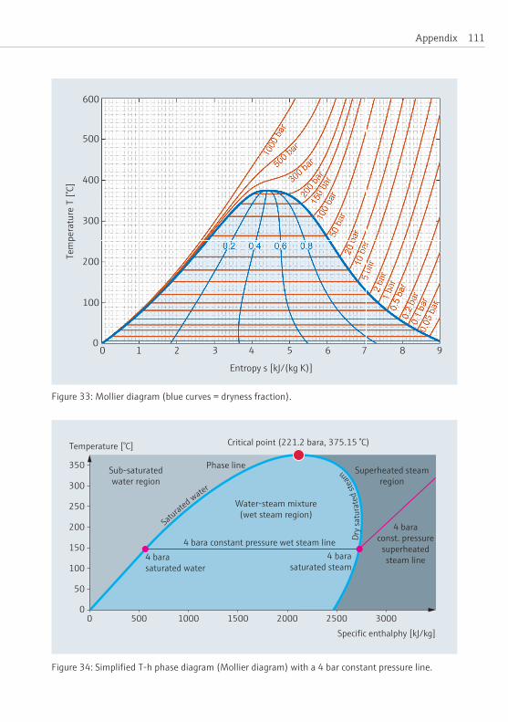
111Appendix
4 bara constant pressure wet steam line
Temperature [°C]
Specific enthalphy [kJ/kg]
Sub-saturatedwater region
Superheated steamregion
Critical point (221.2 bara, 375.15 °C)
Saturated water
Dry s
atur
ated
stea
m
350
150
200
300
250
100
50
00 500 1000 1500 2000 2500 3000
Water-steam mixture(wet steam region)
4 bara saturated water
4 barasaturated steam
4 baraconst. pressure
superheatedsteam line
Phase line
Figure 33: Mollier diagram (blue curves = dryness fraction).
Figure 34: Simplified T-h phase diagram (Mollier diagram) with a 4 bar constant pressure line.
0 1 2 3 4 5 6 7 8 9
Entropy s [kJ/(kg K)]
600
500
400
300
200
100
0
Tem
pera
ture
T [°
C]

Endress+Hauser – Steam Handbook 112
Reverseflameboiler:Inthistypeofboilerthefurnaceisblankended.Theflamepassesthroughthecentreofthefurnace.Thehotgasesimpingeontheblankendofthe furnace and in doing so are reversed in direction, passing back along the furnace wallpriortoexitingthefurnace.
Reversal cell: Awetback or dryback boiler is constructed with a chamber at the end ofthefurnacewhichcausestheflowofcombustionproductstobereversed.Thesecombustion products that pass through a bank of tubes in which further useful heat istransferredfromthegasestothewaterside.
Safety valve:Amechanicalvalvefittedtopressurevesselsintendedtopreventover-pressureeventsbyventingfluidtoatmospherewhenitssetpointisreached.Safetyvalvesarecompletelyindependentofotherprotectionmeasuresandarealwaysfit-tedtosteamboilers.Theyarealsofounddownstreamofpressurereducingvalvesinsteamdistributionsystems.
Saturation point: Thetemperatureandpressureatwhichafluidcannotabsorborgive up further heat without a phase change (see 4 bara example in Figure 34).
Saturated steam: Steam vapor which cannot absorb any additional heat without a consequentincreaseintemperature.Saturatedsteamisoftencalleddry saturated steam.Saturatedsteamliesonthephase linebetweenthewetsteamandsuper-heated steam regions of a phase diagram (see 4 bara example in Figure 34).
Saturated water: Liquid water which cannot absorb additional heat without a phase change occurring (see 4 bara example in Figure 34).
Sensible heat: Heatwhichisaddedtoortakenawayfromafluidwhichresultsinachangeoftemperatureofthefluid.Water,forexample,whichiscooledfrom50°Cto30°Chashadsensibleheatremoved.
Smokebox: Achamberinwhichtheburntcombustiongasesarereversedintheirdirectionofflow,normallynotpartofthepressurevessel.
Specific: A property of a substance which is defined per kilogramme of that substance,e.g.specific heat capacity.
Specificheatcapacity: The amount of heat required to raise the temperature of 1kgofasubstanceby1Kelvin[kJ/(kgK)orkJ/(kg°C)].

113Appendix
Specific energy consumption: The energy consumption of a process per unit of product or the units of steam produced per unit of fuel burnt (this is similar to miles pergallon[mpg]orliterper100km[l/100km]).
Steam hammer: Anoverpressureeventwhichiscausedbythesuddenopeningorclosingofavalve,forexample.Itcanresultindamagetothesteamsystem.Thisphenomenon is explained in more detail on Page 63.
Steam tables: The thermophysical properties of water and steam have been formu-latedbytheInternationalAssociationforthePropertiesofWaterandSteamIAPWS(http://www.iapws.org).Theseformulationsarefrequentlyreproducedintheformof tables known collectively as steam tables although they include all the various phasesofwater.Simplifiedversionsreferencedtobothbaraandbargareproducedbymanyorganizationsandcompanies.ThoseinterestedinfurtherreadingonthissubjectaredirectedtotheIAPWSwebsite.
Steam trap: Adeviceforseparatingcondensatefromsteamandremovingitfromthedistributionsystem.Thereareanumberofdifferenttypescommerciallyavail-able.
Sub-cooling: Usually applied to condensate that has lost some heat resulting in a fluidtemperature less thanthesaturationtemperature.Sub-cooledcondensate isfrequently associated with several forms of water hammer.
Superheated steam: Steam vapor which is above the saturation line but below the criticalpoint.Forexample,ifheatisaddedtosaturatedsteamunderisobariccondi-tionsitstemperaturewillincreaseandthesteambecomessuperheated.Superheat-edsteamisavapor,notagas.Itisverycommonlygeneratedinboilersforpowergenerationorlesscommonlyprocessapplications.Superheatedsteammayalsobefoundinunexpectedsituations,e.g.inanotionallysaturatedsteamdistributionsys-tem due to a sudden reduction in pressure (see 4 bara example in Figure 34).
Supercritical steam: Steam, the pressure and temperature of which is above the critical point.Supercriticalsteamisagas,notavapor.
Swell: see priming.
Three-pass boiler: A boiler arrangedwith a furnace and two convective passes (Figure 9).Theproductsofcombustionpassthroughthefurnaceandtheirdirec-tionisreversedpriortoentrytothefirstconvectivepassinareversalcell.Thisisrepeated prior to entry to the second convective pass (in a smokebox); hence the description“threepass”.

Endress+Hauser – Steam Handbook 114
Total dissolved solids (TDS):Asasteamboilerexportssteamitconcentratesthedissolvedsolidscontainedinthefeedwater.Someoftheconcentratedsolidsremaindissolved.Thisconcentrationisoftenexpressedinpartspermillion.ExcessiveTDSmaycausefoamingatthefreesurfaceofthewaterinsidetheboiler.Thisisundesir-ableasitpromotescarryoverandmaynegativelyaffecttheoperationofthelevelcontrols.
Total dissolved solids blowdown: The TDS naturally concentrates near the free surfaceofthewaterinsidetheboiler.Itiscontrolledbyopeningavalvelocatedjustunderthefreesurface.Thepressureinsidetheboilerforceswateralongwiththedissolvedsolidsoutoftheboiler.
Vapor: Saturatedandsuperheatedsteamarestrictlyavapor,notagas.Avaporiscapableofbeingcompressedbackintotheliquidphaseunderisothermalconditions.
Triple point: The temperature and pressure at which the solid, liquid and vapor phasesofasubstanceareinthermodynamicequilibrium.Forwaterthetriplepointis273.16K(0.01°C)and0.006112bara.
Water hammer: There are several phenomena which are collectively termed “water hammer”: plugflowwaterhammer, condensate-inducedwaterhammerand col-umnclosurewaterhammer.TheseareexplainedindetailonPage 56ff.
Water-tube boiler:Aboilerwhichconsistsof twopressurevesselsconnectedbytubeswithonepressure vessel below theother.The lower vessel contains liquidwaterandisoftenknownasa“muddrum”.Theuppervesselcontainssteamandis known as the “steam drum”. The furnace is external to this arrangement.Asthewaterpassesupthroughthetubesitboilstoformsteam.Thistypeofboileris capableofproducingveryhighpressuresteamwithalargeamountofsuperheat.
Water wedged: Aboilerthathasbeentakenouwtofserviceandcompletelyfilledwithwatertopreventcorrosionoftheinternalsurfacesofthepressurevessel.
Wetback furnace: A furnace inwhich the reversal cell is completely submergedunderthesurfaceofthewaterinsidetheboilerexceptforanaccesshatch.Thistypeoffurnaceincreasestheavailablesurfaceareaforheattransfer.
Wet steam: A liquid-vapor mixture of steam, usually but not always with a high dryness fraction when found in a distribution system during normal operation. Condensate return systems however have a much lower dryness fraction as their purposeistoreturncondensatetotheboilerhouse.

115Appendix
Bibliography•AmericanSocietyofMechanicalEngineersASME(1996–2012).ASME Boiler
and Pressure Vessel Code,NewYork,SectionsItoXII(www.asme.org).
• Fischer,F.(1874).“OntheTheoriesofSteamBoilerExplosions.” Journal of the Franklin Institute,vol.98(5),311–323.
•Goodall,P.M.(ed.)(1980).The efficient use of steam.Guildford:IPCScience andTechnologyPress.
•Holman,J.P.(1981).Heat transfer.5thed.NewYorkandLondon:McGraw-Hill.
• Kreith,F.(1972).Principles of heat transfer.2nded.London:InternationalTextbookCompanyLtd.(reprint).
•Mason,H.(1882).Boiler Explosions Bill Second Reading, HC Deb 22 February 1882,vol.266,1348–1355,http://hansard.millbanksystems.com/commons/1882/feb/22/second-reading(seenon:8December2016).
•MinistryofHousingandLocalGovernment(ed.)(1956).Clean Air Act, 1956 (4&5Eliz.2CH.52).London:HMSO.
•Murray,M.V.(1959).“TheShellBoiler:AnHistoricalReview.” Journal of the Institute of Fuel,vol.32(224),425–433.
• Petukhov,B.S.(1970).“Heat Transfer and Friction in Turbulent Pipe Flow withVariablePhysicalProperties.”Hartnett,J.P.andIrvine,Jr.T.F.(eds). Advances in heat transfer,vol.6,503–564.
• Pole,William(ed.)(1970).The Life of Sir William Fairbairn, Bart. NewtonAbbot:David&CharlesPublishers,258–268.
• Rolt,L.T.C.(1960).The Cornish Giant: The Story of Richard Trevithick, Father of the Steam Locomotive.London:TheCamelotPress,p.168.
• Stevens,A.(n.d.).Steam Pipe Insulation.TheRoyalAcademyofEngineering,http://www.raeng.org.uk/publications/other/2-steam-pipe(seenon: 8December2016).

Endress+Hauser – Steam Handbook 116

117Index
Index
AAdiabaticprocess106Airtemperature,combustion89AmericanSocietyofMechanical
Engineers(ASME)9ASMEBoilerandPressureVessel
Code 9
BBaseexchangesoftening26BLEVE (Boiling liquid expanding
vapor explosion) 55Blowdown
TDS blowdown 27Blowdown pit 106Blowdown, TDS 114Blowdown vessel 14, 106Boiler
Evaporation test 72Instrumentation 87Management 68Tests and checks 71
Boiler blowdownBottom blowdown 14TDS blowdown 14
Boiler controlEN 12953 24Instrumentation 87
Boiler designsCoil steam generator
(once-through boiler) 17Cornish boiler 7, 8, 21Fire-tube boiler 21, 108History 7Lancashire boiler 8MTHSboiler(fire-tubeor
smoke-tube boiler) 21ReverseflameMTHSboiler23
Shell boiler 21Smoke-tube boiler 21Three-passboiler(definition)113Three-pass wetback MTHS boiler 23Water-tube boiler 19, 114
Boilerefficiency73Direct method 80, 107Indirect method 73, 109
Boiler explosion 26, 27, 28, 55, 70Boiler horsepower 106Boiler house 69Boiler market (Europe) 93Boiler operation (trouble-shooting,
maintenance, tests, checks) 67Boiler pressure 14Boiler rating 22Boiler shutdown 14, 26Bottom blowdown 14, 27, 106Burner shutdown 25, 28Burners (single-fuel, dual-fuel) 30
CCalorificvalue80Carbon monoxide 76Carryover 91, 106Cavitation 107Chemicals 14CleanAirAct10Cleaning in place (CIP) 28Coil steam generator
(once-through boiler) 17Combustion air temperature 89Condensate 15, 33, 107Condensate, contamination 28, 90Control valve 35Cornish boiler 7, 8, 21Corrosion 26

Endress+Hauser – Steam Handbook 118
Cost (boiler fuel) 97Critical point 107Crown valve 107
DDarcy-Weisbach equation 43Deadleg 107Deaerator 14De-alkalization 26Degrees of superheat 107Demineralization 26Desuperheater 107Direct heating 15Dissolved oxygen 14Dryback furnace 108Dry fry 61, 108Dryness fraction 108Dry saturated steam 108
EEconomic boiler 9Economizer 24, 108Efficiency.See BoilerefficiencyEmissions 30Energy consumption 113Enthalpy 108Entropy 108Evaporation test 72Exhaust gas composition 79Exhaust gases 76Exhaust temperature 76, 89Explosion.See Boilerexplosion
FFeedwater 14, 25Feedwater control 29Feedwater meter 89Feedwater temperature 89Filtration 26Fire-tubeboiler.See MTHSboiler
Flame detector 31Flame failure device 25Flash steam
First type 108Second type 109
Flash steam explosion 61Flowmeter (steam meter) 88Foaming 91Fouling (gas side, water side) 76From and at 100 °C 22, 109Fuel composition 80Fuel meter 88Fuel-to-steamefficiency80Furnace 30Furnace collapse 70
GGauge pressure 109Grashof Number (Gr) 104GrossCalorificValue(GCV)109
HHazards of steam 55Heat capacity 112Heat carrier 109Heat exchanger 28Heating
Direct heating 15Higher heating value (HHV) 73Indirect heating 15Lower heating value (LHV) 73
HotwellDefinition109Level 91Temperature 90
IImpurities (raw water) 26Indirect heating 15Insurance 9Isenthalpic 109

119Index
Isentropic 109Isolation valve 35
LLancashire boiler 8, 21Latent heat 110Legislation 9Level control 25, 28, 71, 90Level control systems 29Low water condition 110l-v (liquid-vapor) mixture 109
MMake-up water 13ManchesterSteamUsersAssociation
for the Prevention of Steam Boiler Explosions 9
Maximum continuous rating (MCR) 110
Milk 28Mollier diagram 110MTHSboiler(definition)108MTHSboiler(fire-tubeorsmoke-tube
boiler) 21, 30MTHSboiler,reverseflame23
NNetCalorificValue(NCV)110Nitrogen oxid (NOx) 76Nusselt Number (Nu) 104
OOnce-through boiler
(coil steam generator) 17Osmosis, reverse (RO) 26Over-firing71Overpressure 61Oxygen content 89Oxygen, dissolved 14
PPhase diagram 110pH value 14Prandtl Number (Pr) 104Pressure, absolute 106Pressure (boiler) 14Pressure compensation 53Pressure control 25Pressure cycles 69Pressure drop (in pipes) 45Pressure gauge 35Pressure reducing valve (PRV)
15, 35, 110Pressure transmitter 88Priming 26, 28, 110Priming (carryover) 91
RRecord keeping 72Regulations (boiler)
BS 3059:1990 94BS EN 10217-1:2002 94EN 12953 94PD 2790 (UK standard) 94Pressure Equipment Directive (PED)
94Reversal cell 112Reverseflameboiler112ReverseflameMTHSboiler23Reverse osmosis (RO) 26Reynolds Number (Re) 105
SSafety valve 33, 112Saturated steam 112Saturated water 112Saturation point 112Scale, scaling 25, 27Sensible heat 112Shell boiler 7, 21

Endress+Hauser – Steam Handbook 120
Shell losses 79Smokebox 112Smoke-tube boiler 21, 108Society of German Engineers 9Specificenergyconsumption113Specificheatcapacity112Steam applications 11Steamboilertypes.See BoilerdesignsSteam bulk velocity 33Steam distribution 14, 33Steamexplosion.See BoilerexplosionSteam hammer 63, 113Steam impurities 14Steam motion
Detailed explanation 41Simple explanation 37
Steam properties 11Steam quality 24Steam system (scheme) 13Steam tables 113Steam trap 15, 33, 36, 113Strainers 36Sub-cooling 113Supercritical steam 20, 113Superheated steam 107, 113Superheater 22Superheater tubes 19Swell.See Priming
TTemperature compensation 53Temperature gauge 35Three-pass boiler
Definition113Three-pass wetback MTHS boiler 23
Total dissolved solids (TDS) 14, 91, 114
Trending information (fuel,steam,etc.)83
Trevithick, Richard 7
Triple point 114Turn-down ratio (burner) 30
VVacuum draw 64Valves
Check valve 35Control valve 35Crown valve 107Isolation valve 35Non-return valve 35PRV (Pressure Reducing Valve) 35Safety valve 33, 112
Vapor 114
WWater hammer 114
Colum collapse water hammer 56Plugflowwaterhammer62Sub-cooled condensate-induced 59
Water level 14Waterlogging 65Waterside explosion 70Water treatment 25Water treatment methods
Baseexchangesoftening26De-alkalization 26Demineralization 26External treatment 27Filtration 26Internal treatment 27Reverse osmosis (RO) 26
Water-tube boiler 19, 114Water wedged 114Wetback furnace 114Wetness 24Wet steam 114

121Index

CP01
195D
/06/
EN/0
1.17