Embed Size (px)
Citation preview

An Introductionto SpreadSpectrumSystems
ERIK STROM, TONY OTTOSSON, ARNE SVENSSONDepartment of Signals and SystemsCHALMERS UNIVERSITY OF TECHNOLOGY
Goteborg, Sweden, 2002


REPORT NO. R016/2002
An Introduction to Spread Spectrum Systems
ERIK STROM, TONY OTTOSSON, ARNE SVENSSON
Department of Signals and SystemsChalmers University of Technology
Goteborg, Sweden, 2002
i

An Introduction to Spread Spectrum SystemsERIK STROM, TONY OTTOSSON, ARNE SVENSSON
c© ERIK STROM, TONY OTTOSSON, ARNE SVENSSON, 2002
Technical report no. R016/2002Department of Signals and SystemsChalmers University of TechnologySE-412 96 GoteborgSwedenTelephone +46 (0)31-772 1000
Second corrected printing, January 7, 2004
Printed by School of Electrical Engineering, Chalmers University of TechnologyGoteborg, Sweden 2002
ii

Abstract
This report is a tutorial introduction to spread spectrum communicationsystems, and it should be accessible for a reader who has basic knowledge ofdigital modulation and channel coding. The authors have chosen to presentthe more advanced topics in the report from a signal space and channel cod-ing point of view. While other approaches are certainly possible, the authorsfeel that the chosen approach is the most beneficial for the communicationsengineer. Since the original applications for spread spectrum systems weremilitary, we will introduce spread spectrum links as a means of overcomingintentional jamming. The reader who dislikes military applications may becomforted by the fact that the problem of communicating in the presenceof jamming is very much akin to the problem of communicating over fadingchannels. Hence, by finding out how to defeat jamming by spread spec-trum will also reveal how to overcome fading. Today, spread spectrum linksare also used in many civilian systems to overcome nonintentional jamming(or interference), and the report is concluded with an overview of currentcommercial spread spectrum systems.
The authors welcome comments and corrections to the material. Pleasesend these to Erik Strom at [email protected].
iii

iv

Contents
1 Introduction 1
2 A Simple Jamming Game 2
3 Direct-Sequence Spread Spectrum 53.1 Transmitted Signal and Receiver Structure . . . . . . . . . . . . . . 53.2 DS-SS and Broadband Continuous Noise Jamming . . . . . . . . . . 93.3 DS-SS and Narrowband Jamming . . . . . . . . . . . . . . . . . . . 103.4 Pulsed Jamming . . . . . . . . . . . . . . . . . . . . . . . . . . . . 113.5 Repetition Coding and Interleaving . . . . . . . . . . . . . . . . . . 133.6 Signal Space Interpretation . . . . . . . . . . . . . . . . . . . . . . . 18
4 Frequency-Hopping Spread Spectrum 194.1 Broadband Noise Jamming . . . . . . . . . . . . . . . . . . . . . . . 214.2 Partial-Band Noise Jamming . . . . . . . . . . . . . . . . . . . . . . 224.3 Multitone Jamming . . . . . . . . . . . . . . . . . . . . . . . . . . . 224.4 Repetition Coding and Interleaving . . . . . . . . . . . . . . . . . . 23
5 Commercial Spread Spectrum Systems 23
v

vi

Strom, Ottosson, Svensson: An Introduction to Spread Spectrum Systems 1
1 Introduction
Spread spectrum systems is a class of (primarily) wireless digital communicationsystems specifically designed to overcome a jamming situation, i.e., when an ad-versary intends to disrupt the communication. To disrupt the communication, theadversary needs to do two things, (a) to detect that a transmission is taking placeand (b) to transmit a jamming signal which is designed to confuse the receiver. Aspread spectrum system is therefore designed to make these tasks as difficult aspossible. Firstly, the transmitted signal should be difficult to detect by an adver-sary, i.e., the signal should have a low probability of intercept (LPI). Secondly, thesignal should be difficult to disturb with a jamming signal, i.e., the transmittedsignal should possess an anti-jamming (AJ) property.
Clearly, the intentional jamming situation is most common in a military con-text, and spread spectrum systems were originally developed specifically for mili-tary applications. (For an interesting review of the history of the spread spectrumin the West in general and the US in particular, we can recommend the papers[1, 2, 3] or chapter 2 of [4].) However, in later years, spread spectrum systems havebeen introduced in many commercial applications that require good anti-jammingproperties. An example of commercial spread spectrum systems are systems thatare designed to be used in so-called unlicensensed bands, such as the Industry,Scientific, Medical (ISM) band around 2.4 GHz. Typical applications are herecordless telephones, wireless LANs, and cable replacement systems as Bluetooth.Since the band is unlicensed, there is no central control over the radio resources,and the systems have to function even in the presence of severe interference fromother communication systems and other electrical and electronic equipment (e.g.,microwave ovens, radars, etc.). Here the jamming is not intentional, but the inter-ference may nevertheless be enough to disrupt the communication for non-spreadspectrum systems.
Code-division multiple access systems (CDMA systems) use spread spectrumtechniques to provide communication to several concurrent users. CDMA is used inone second generation (IS-95) and several third generation wireless cellular systems(e.g., cdma2000 and WCDMA). One advantage of using jamming-resistant signalsin these applications is that the radio resource management (primarily the channelallocation to the active users) is significantly reduced.
The name spread spectrum stems from the fact that the transmitted signalsoccupies a much wider frequency band than what is necessary. This enables thetransmitter to hide its signal in a large bandwidth. There are many different waysto use the bandwidth. The most common ones are called direct-sequence (DS) andfrequency-hopping (FH) spread spectrum (SS). In FH-SS, the transmitter changesthe carrier frequency of the relatively narrowband transmitted signal in a fashionwhich appears random to the jammer. At any given time, only a small fraction ofthe available bandwidth is used, and exactly which fraction is made a secret for thejammer. The jammer is therefore uncertain where in the system bandwidth thesignal is being transmitted, and it is difficult for the jammer to detect and disturbthe transmitted signal. In DS-SS, the power of the transmitted signal is spreadover the entire system bandwidth in a way that looks random for the jammer.
Technical report no. R016/2002, ISSN 1403-266X

2 Strom, Ottosson, Svensson: An Introduction to Spread Spectrum Systems
Again, this makes the signal hard to detect and to jam. Several other spreadspectrum strategies are available; however, the clear majority of the implementedsystems are either frequency-hopping or direct-sequence (or hybrids of these basicschemes).
The bandwidth necessary for the transmission of a digital communications sig-nal is determined by the data rate, Rb, (measured in the number of information bitstransmitted per second) and the chosen modulation format. For binary passbandmodulation (suitable for wireless transmission), the minimum required bandwidthis approximately Wmin = Rb Hz. If we denote the actual bandwidth of the trans-mitted signal by Wss, then for a spread spectrum system Wss � Rb. The spectralefficiency of the spread spectrum communication link is Rb/Wss bits/second/Hz.By definition, the spectral efficiency of a spread spectrum system is very low. Thisseems to render spread spectrum techniques useless for systems that need to usespectrum efficiently. However, this is not necessarily the case since several usersusing spread spectrum signals can share the same bandwidth (at the same time),and the system’s spectral efficiency (measured in the total number of informationbits transmitted per second) may be still be very good, even if the individual linkshave low spectral efficiencies.
The literature in the field of spread spectrum communications is quite volu-minous and ranges from text books to specialized conference and journal papers.Among the available books, we would like to especially mention the text by Simon,Omura, Scholtz, and Levitt [4] which covers quite a lot of the classical spread spec-trum techniques and which has inspired this presentation to a large degree. Thebooks by Peterson, Ziemer, and Borth [5] and by Dixon [6], which cover more of thecurrent commercial applications, are also recommended. The reference lists of theabovementioned books contain several thousand entries. Among the tutorial-stylepapers that are available in the literature, we would like to especially mention the1982 paper by Pickholtz, Schilling, and Milstein [7].
In this report, we will concentrate on describing the anti-jamming propertyof spread spectrum systems. Moreover, we will limit our discussion to the twomain forms of spread spectrum: direct-sequence and frequency-hopping spreadspectrum. We will try to cover DS spread spectrum in some detail, but manyissues will be skimmed and the FH discussion will be quite brief.
2 A Simple Jamming Game
Let us study a simple example to illustrate the basic concepts and ideas of spreadspectrum. Let the average received communication signal power and receivedjamming signal power be denoted by S and J , respectively. We ignore any otherinterference, such as thermal noise, at this stage. The basic question is “How canwe communicate reliably even when J � S?”.
Actually, we know the answer from basic communication theory. We know thatwe can communicate over a channel disturbed by additive white Gaussian noise (anAWGN channel). White noise has infinite power, but since the power is spread overan infinite number of signal space dimensions (or infinite bandwidth), the power
Technical report no. R016/2002, ISSN 1403-266X

Strom, Ottosson, Svensson: An Introduction to Spread Spectrum Systems 3
per signal space dimension is finite. Hence, by concentrating the transmitter powerto a finite-dimensional signal space, we can gain a power advantage over the noise.
The same idea is used in a jamming situation. However, we must make thechoice of signal space dimensions used for transmission a secret for the jammer.Otherwise, the jammer can concentrate its power to the same dimensions, andnothing is gained. This implies that we need to hide the transmitted signal in aspace with many more dimensions than what is needed for the transmitted signal.
From the work by Landau, Pollak, Slepian and others [8, 9, 10, 11], we knowthat the dimensionality of a signal space depends on duration and bandwidth ofthe signals in the space. Suppose the spread spectrum bandwidth (or systembandwidth) is Wss. That is, the transmitted signal must reside in a frequencyband of width Wss Hz. If the data rate (number of information bits transmittedper second) is Rb = 1/Tb, then the transmission of a (long) packet of P informationbits will take approximately Tp seconds, where
Tp = PTb =P
Rb
.
It has been shown that the set of all signals that are (essentially) time-limited toTp seconds and (essentially) bandlimited to Wss Hz spans a signal space of (ap-proximately) Np = 2WssTp dimensions. Hence, the number of dimensions availablefor the transmission of one information bit is
Nd =Np
P= 2
Wss
Rb.
A characteristic of a spread spectrum system is that ratio Wss/Rb is very large. Asa matter of the fact, the larger the ratio the more resistant to jamming the systemcan be made. The number Wss/Rb is often called the processing gain; however,the reader should be cautioned that processing gain is not a well-defined term.Indeed, in the literature many other definitions exist.
If the jammer has no idea which subset of the Nd dimensions that is used for thetransmission, it may decide to spread its power equally over all dimensions. Thejamming signal can then be viewed as a noise waveform with flat power spectrumover the system bandwidth, see Figure 1. The spectral height of the jammingsignal is denoted NJ/2, where
J = 2WssNJ
2= WssNJ .
This type of jamming is called broadband noise jamming, and from now on we willassume that the noise is Gaussian. As we will see later, broadband noise jammingis perhaps the most benign form of jamming, and much effort is put into the designof spread spectrum systems to force the jammer into this jamming strategy.
To quantify the effect of broadband noise jamming, let us consider the effect ona binary antipodal modulation format, such as binary phase-shift keying (BPSK).The bit error probability is (assuming perfect synchronization and ideal coherentdetection)
Pb = Q
(√2
Eb
NJ
),
Technical report no. R016/2002, ISSN 1403-266X

4 Strom, Ottosson, Svensson: An Introduction to Spread Spectrum Systems
2
JN
ssW ssW
f
Figure 1: Power spectral density of a broadband (nonpulsed) noise jammer.
where Eb = STb = S/Rb is the received energy per information bit and
Q(x) =1√2π
∫ x
−∞e−t2/2 dt.
As seen from Figure 2, the bit error probability is decreasing exponentially withEb/NJ , and since
Eb
NJ=
S/Rb
J/Wss=
S
J
Wss
Rb,
we can reach any bit error probability for any jammer-to-signal power ratio, J/S,by making the processing gain large enough. However, we should remember thatwe have reached this conclusion under idealized circumstances. For instance, if thejamming causes the synchronization or front-end electronics or processing to fail,then this will effectively disrupt the communication.
We are now ready to characterize a spread spectrum system as a system forwhich the follwing holds.
1. The system (spread spectrum) bandwidth is (much) larger than the infor-mation bit rate.
2. The bandwidth expansion achieved by a process which is independent of thetransmitted data.
The second requirement has to do with the fact that the choice of dimensionsmust be made a secret for the jammer. This definition may not be completelyunambiguous and has been criticized by, e.g., Massey who in [12] offers a differentdefinition.
For any given type of spread spectrum system, there will be a worst-case jam-ming strategy (worst-case from the communicator’s point of view). However, thereis no jamming strategy which is worst-case for all conceivable spread spectrum for-mats. The vice versa is also true; there exist no spread spectrum format whichis optimum for all jamming strategies. Hence, many types of spread spectrumsystems have been proposed and are used. As mentioned earlier, the most com-mon types are direct-sequence spread spectrum (DS-SS), frequency-hopping spreadspectrum (FH-SS), and hybrids of these.
Technical report no. R016/2002, ISSN 1403-266X

Strom, Ottosson, Svensson: An Introduction to Spread Spectrum Systems 5
0 1 2 3 4 5 6 7 8 9 1010
−6
10−5
10−4
10−3
10−2
10−1
Pb
Eb/N
J in dB
Figure 2: Bit error probability for BPSK-modulated DS-SS and broadband (non-pulsed) noise jamming. Coherent detection and perfect synchronization is as-sumed.
3 Direct-Sequence Spread Spectrum
3.1 Transmitted Signal and Receiver Structure
We will present two receiver structures and two ways to produce the transmittedsignal for a DS-SS system. The first approach is to view the bandwidth expansionas result of repetition coding followed by a randomizing scrambling. The secondapproach views DS-SS as regular BPSK modulation where the bandwidth expan-sion is a result of (randomly) choosing a wideband pulse shape. The two modelsare equivalent in that the transmitted signal is the same and that the receivershave the same performance. Nevertheless, it is worthwhile to be aware of bothmodels since they both add insight to the problem.
Let us first consider an ordinary uncoded BPSK system. The transmittedsignal can be written as
s(t) =√
2Eb cos(2πfct)
∞∑n=−∞
b[n]p(t − nTb),
where Eb is the energy per information bit, fc is the carrier frequency, b[n] ∈ {±1}is the nth information bit, p(t) is the unit-energy pulse shape, and the data rate isRb = 1/Tb. The bandwidth of s(t) is determined by the pulse shape and data rate(assuming that the data sequence is white). For instance, if the pulse has a root-
Technical report no. R016/2002, ISSN 1403-266X

6 Strom, Ottosson, Svensson: An Introduction to Spread Spectrum Systems
raised cosine spectrum with roll-off factor α, the bandwidth of the transmittedsignal is (1 + α)Rb ≈ Rb for small α.
If we instead use a rectangular pulse shape
p(t) =
{1√Tb
, 0 ≤ t < Tb
0, otherwise,
the transmitted signal will no longer be strictly bandlimited. However, if we usethe null-to-null bandwidth measure, the bandwidth is 2Rb Hz, see Figure 3. Itcan be shown that more than 90% of the total power of the transmitted signal iscontained in the null-to-null bandwidth.
−3/T −2/T −1/T 0 1/T 2/T 3/T−40
−35
−30
−25
−20
−15
−10
−5
0
10 lo
g 10 |P
(f)|
2
Figure 3: Plot of the magnitude square of the Fourier transform of a rectangularpulse of width T seconds (in dB-scale). Clearly, the null-to-null bandwidth is 1/Tfor the baseband signal and 2/T for a passband signal.
We can achieve an increase of the bandwidth to Wss = N2Rb by (a) repeatingevery information bit N times and (b) randomizing the repeated information bitswith a scrambling code (or spreading code) c[m]. The procedure is illustrated inFigure 4. Since the bandwidth is increased with a factor of N , the number N isknown as the spreading factor.
The rate after the repetition encoder is NRb = N/Tb and the transmitted(channel) bits are
d[m] = c[m]b[�m/N�],
where �·� denotes the floor function (rounds down to closest integer). The channelbits are also known as chips, and the channel bit rate is called the chip rate1/Tc = NRb. The scrambling code should appear random to the jammer, but
Technical report no. R016/2002, ISSN 1403-266X

Strom, Ottosson, Svensson: An Introduction to Spread Spectrum Systems 7
[ ]b n
2 cos(2 )c cE f t�
( )s tPAM
p(t)
Repetition
with a
factor N
[ ]c m
[ ]d m
rate 1/Tb
rate 1/Tc
[ ] ( )c
m
d m p t mT�
���
��
Figure 4: Modulator for DS-SS with BPSK modulation with an arbitrary chipwaveform p(t). (PAM stands for pulse amplitude modulation.)
must also be reproducible by the receiver. Pseudo-random noise sequences fitsthese requirements and are often used as scrambling codes [13].
The transmitted signal of a DS-SS system with BPSK modulation is
s(t) =√
2Ec cos(2πfct)∞∑
m=−∞d[m]p(t − mTc),
where Ec = Eb/N is the energy per chip and p(t) is the chip pulse shape (assumedto have unit energy).
This arrangement now fulfills the requirement for being a spread spectrum sys-tem: the bandwidth of the transmitted signal is larger than Rb and the bandwidthexpansion is done by the scrambling code, which is independent of the transmitteddata. For the special case of rectangular chip pulses, we can rewrite the transmit-ted signal as
s(t) =
√2Eb
Tb
cos(2πfct)b(t)c(t)
where the data signal b(t) is defined as
b(t) =∞∑
n=−∞b[n]ΠTb
(t − nTb)
and the scrambling waveform is defined as
c(t) =
∞∑m=−∞
c[m]ΠTc(t − mTc),
and ΠT (t) denotes a unit-amplitude rectangular pulse of duration T seconds. Ablock diagram of the modulator is found in Figure 5.
We observe that the scrambling waveform c(t) is found by pulse amplitudemodulating the scrambling code c[m] with the chip pulse shape. The scramblingcode is designed to behave as discrete-time white noise, and we can model thechips as being independent and equally likely ±1. Hence, the bandwidth of c(t) isdetermined by the bandwidth of ΠTc(t) which has null-to-null bandwidth 1/Tc Hz
Technical report no. R016/2002, ISSN 1403-266X

8 Strom, Ottosson, Svensson: An Introduction to Spread Spectrum Systems
[ ]b n
2cos(2 )b
c
b
Ef t
T�
( )s t
rate 1/Tb
[ ] ( )cT c
m
d m t mT�
���
� ��
( )b t
[ ]c m PAM
( )cT t�
( )c t
PAM
( )bT t�
rate 1/Tc
Figure 5: Modulator for DS-SS with BPSK modulation and rectangular chip wave-forms.
(recall that c(t) is a baseband signal and its power spectral density is propor-tional to the magnitude squared of the Fourier transform of ΠTc(t), see Figure 3).A similar argument reveals that b(t) has bandwidth 1/Tb, and that the productc(t)b(t) has the same bandwidth as c(t), i.e., 1/Tc = N/Tb = NRb Hz. Finally, af-ter modulation with the carrier, the transmitted waveform will have a null-to-nullbandwidth of 2/Tc = 2N/Tb = 2NRb Hz.
It is now clear that by multiplying b(t) with c(t), we obtain a bandwidthexpansion, or spreading, of a factor of Tb/Tc = N . This is why c(t) is also calledthe spreading waveform and c[m] is called the spreading code.
We have presented two views on how the DS-SS transmitted signal is produced.The first one says that the bandwidth expansion is achieved through channel coding(repetition coding), and the second says that the bandwidth expansion is donethrough a change of the pulse shape. We can also form the receiver from these twoperspectives. The receiver from the channel coding perspective is a demodulatorfollowed by a channel decoder, see Figure 6. Hence, the receiver consists of adown-mixing stage (multiplication by a locally generated carrier) followed by afilter which is matched to the chip pulse shape and sampled at chip rate. Thesampled output of the chip matched filter is descrambled by multiplying with alocally generated copy of the scrambling code. The descrambled chips are fed tothe repetition code decoder which outputs the information bit decisions.
The receiver from a modulation perspective is just a down-mixing stage fol-lowed by a filter which is matched to consecutive Tb-segments of c(t) (a so-calledcode matched filter). A block diagram of the receiver where the matched filter isimplemented with a correlator is found in Figure 7.
Technical report no. R016/2002, ISSN 1403-266X

Strom, Ottosson, Svensson: An Introduction to Spread Spectrum Systems 9
2 cos(2 )cf tπ
( )−p t( )r t
ct mT=
sgn{ }⋅[ ]b n
Chip matched filter
[ ]c m
( 1) 1
( )n N
m nN
+ −
=
⋅∑
Repetition code decoder
Figure 6: Demodulator for DS-SS with BPSK modulation with an arbitrary chipwaveform p(t).)
2 cos(2 )cf t�
( )b
t
t Tdt
���
( )c t
( )r tbt nT�
sgn{ }�[ ]b n
Code matched filter
Figure 7: Demodulator for DS-SS with BPSK modulation with rectangular chipwaveform.
3.2 DS-SS and Broadband Continuous Noise Jamming
For rectangular chip pulses, the receivers presented in Figures 6 and 7 are equiv-alent and optimum, in the sense that the bit error probability is minimized if thereceived signal is equal to the transmitted signal plus white Gaussian noise. Hence,if the jammer waveform is Gaussian noise that is spectrally white over the systembandwidth and if we ignore any other interference (such as thermal noise), the biterror probability is
Pb = Q
(√2
Eb
NJ
). (1)
If we assume that the channel also adds white Gaussian noise with power spectraldensity N0/2, then the resulting bit error probability is
Pb = Q
(√2
Eb
NJ + N0
),
which is illustrated in Figure 8.
Note that the processing gain only affects NJ = JRb/Wss. Hence, the band-width expansion does not help at all to combat the white channel noise. However,by replacing the repetition code with a better channel code, we can combat boththe jamming and the channel noise more efficiently.
Technical report no. R016/2002, ISSN 1403-266X

10 Strom, Ottosson, Svensson: An Introduction to Spread Spectrum Systems
0 5 10 15 20 25 30 3510
−5
10−4
10−3
10−2
10−1
Pb
Eb/N
J in dB, E
b/N
0 fixed at 8.4 dB
Bit error probability due to jamming and AWGNBit error probability due to jamming only Bit error probability due to AWGN only
Figure 8: Bit error probability for DS-SS with BPSK modulation over an AWGNchannel with Eb/N0 = 8.4 dB and with broadband noise jamming of varying power.
3.3 DS-SS and Narrowband Jamming
DS-SS is also effective against narrowband jamming and interference. This isperhaps easiest seen from the modulation point of view.
Let us study a system with rectangular chip waveforms and transmitter andreceiver as in Figures 5 and 7, respectively. Furthermore, suppose the jammingsignal is a pure cosine at the carrier frequency with power J and phase θ, i.e.,
j(t) =√
2J cos(2πfct + θ).
The contribution from the jammer to the input to the integrator block in Figure 7is
j(t)√
2 cos(2πfct)c(t) =√
Jc(t)2 cos(2πfct + θ) cos(2πfct)
=√
Jc(t)[cos(θ) + cos(4πfct + θ)]
=√
Jc(t) cos(θ) +√
Jc(t) cos(4πfct + θ).
The second term in the equation above will have its power centered around twicethe carrier frequency, and since the integrator is a lowpass filter, this term willbe suppressed almost completely. The first term has its power centered aroundDC and is spread over the entire system bandwidth (maximum frequency approx-imately 1/Tc Hz). Again, since the integrator is a lowpass filter with a cut-offfrequency of approximately 1/Tb Hz, only a fraction of the jammer power willremain after the integrator.
Technical report no. R016/2002, ISSN 1403-266X

Strom, Ottosson, Svensson: An Introduction to Spread Spectrum Systems 11
The same type of argument can be made for a more general narrowband jam-ming signal. The receiver will spread the power of the jamming signal to spanapproximately the entire system bandwidth, and the integrator will lowpass filterthe spread jamming signal. Hence, only a small fraction of the jammer power willeffect the decisions on the information bits. However, the desired signal compo-nent will be despread by the receiver. The desired signal component at the inputto the integrator in Figure 7 is
c2(t)b(t)
√Eb
Tb
2 cos2(2πfct) = b(t)
√Eb
Tb
+ b(t)
√Eb
Tb
cos(4πfct),
and the integrator serves as a matched filter for the data signal b(t). The spreadingof the jammer signal and despreading of the desired signal operation is conceptuallyillustrated in Figure 9.
lowpass
filter
( )c t
( ) ( ) ( ) ( )r t b t c t j t� � ( ) ( ) ( )b t j t c t� ( ) LP{ ( ) ( )}b t j t c t�
signal
jammer
jammer
signal
jammer
signal
f f f
Figure 9: Despreading operation in the presence of narrowband jamming. Theplots show the power spectral densities at various points in the despreading circuit(double frequency terms are neglected in this figure).
3.4 Pulsed Jamming
One very effective jamming strategy for DS-SS is a broadband pulsed noise jam-mer. A broadband pulsed noise jammer transmits noise whose power is spreadover the entire system bandwidth. However, the transmission is only on for afraction ρ of the time (i.e., ρ is the duty cycle of the jammer transmission and0 < ρ ≤ 1). This allows the jammer to transmit with a power of J/ρ when it istransmitting (remember that J is the average received jammer power), and theequivalent spectral height of the noise is NJ/2ρ.
To make a simple analysis of the impact of a pulsed jammer we start by as-suming that the jammer affects an integer number of information bits. That is,during the transmission of a certain information bit, the jammer is either on (withprobability ρ) or off (with probability 1 − ρ). Furthermore, if we assume that thejammer waveform is Gaussian noise and ignore all other noise and interference,
Technical report no. R016/2002, ISSN 1403-266X

12 Strom, Ottosson, Svensson: An Introduction to Spread Spectrum Systems
the bit error probability for a DS-SS system with BPSK modulation (coherentdetection and perfect synchronization) is
Pb = (1 − ρ) × 0 + ρQ
(√2Eb
NJ
ρ
)= ρQ
(√2Eb
NJ
ρ
).
For a fixed Eb/NJ (e.g., for a fixed processing gain and fixed average receivedjammer and signal powers), the worst case jammer duty cycle can be found to be
ρwc =
{0.709
Eb/NJ, Eb
NJ> 0.709
1, Eb
NJ≤ 0.709
,
and the corresponding bit error probability is
Pb =
⎧⎨⎩
0.083Eb/Nj
, Eb
NJ> 0.709
Q(√
2Eb
NJ
), Eb
NJ≤ 0.709
.
This situation is illustrated in Figure 10. If the jammer uses the worst-case dutycycle, then the bit error probability is only decaying as 1/(Eb/NJ) rather thanexponentially in Eb/NJ . As seen from the figure, to reach Pb = 10−4 we haveto spend almost 21 dB more signal power compared to case for a broadbandcontinuous noise jammer.
0 5 10 15 20 25 30 35 4010
−7
10−6
10−5
10−4
10−3
10−2
10−1
Pb
Eb/N
J in dB
Worst case duty cycle Broadband noise jammer
ρ = 1
0.1
0.01
0.001
Figure 10: Bit error probability for BPSK-modulated DS-SS with pulsed noisejamming with duty cycle ρ.
Technical report no. R016/2002, ISSN 1403-266X

Strom, Ottosson, Svensson: An Introduction to Spread Spectrum Systems 13
3.5 Repetition Coding and Interleaving
The pulsed jammer situation is similar to a flat fading channel: at some times thechannel is very bad, and this dominates the bit error probability. The remedy toovercome a pulse jammer is the same as for a flat fading channel. We introducechannel coding and interleaving to gain diversity.
Luckily, the DS-SS format has a built-in channel code (the repetition code), andwe just need to introduce an interleaver before the BPSK modulator in Figure 4and a deinterleaver in front of the descrambler in Figure 6. We will assume a blockinterleaver. That is, N consecutive chips (that corresponds to an information bit)are divided into m blocks of N/m chips (assumed to be an integer), and the blocksare interleaved. The parameter m must of course be less or equal to N .
With a sufficiently large interleaver depth, each chip will see an independentchannel. The input to the channel decoder (i.e., the signal after deinterleaving) inFigure 6 during a certain bit interval is
r[k] =√
Ecb + z[k]n[k],
where b is the information bit, z[k] is binary random variable which is 1 if the chipwas jammed and 0 if the chip was not jammed, and n[k] is a Gaussian randomvariable with variance NJ/2ρ. We make the assumption that z[k] = 1 with proba-bility ρ, i.e., we assume that during the transmission of a chip, the jammer is eitheron or off. Moreover, we make the assumption that an interleaved block of chips,i.e., a block of N/m consecutive chips are either jammed or not jammed with theprobability ρ and 1 − ρ, respectively. This means that each interleaved block willsee an independent channel, and that the channel is bad with probability ρ andgood (perfect) with probability 1−ρ. Hence, the parameter m is also the diversityorder of the system.
The variable z[k] represents the channel state information (CSI), which mayor may not be available for the receiver (it is quite conceivable that the receiveris able to estimate which chips that have been jammed by, e.g., monitoring thereceived signal power). In the absence of CSI, the receiver can form the decisionas the sign of
N−1∑n=0
r[n] =m−1∑l=0
(l+1)N/m−1∑k=lN/m
r[k],
where the right-hand side shows that the contributions from all interleaved blocksare simply added together (so-called equal gain combining). The above strategyis known as soft decoding without CSI, and the bit error probability is
Pb =m∑
l=1
Pr{l blocks are jammed}Pr{bit error if l blocks are jammed},
and since (if ρ < 1)
Pr{l blocks are jammed} =
(m
l
)ρl(1 − ρ)m−l
Technical report no. R016/2002, ISSN 1403-266X

14 Strom, Ottosson, Svensson: An Introduction to Spread Spectrum Systems
and
Pr{error if l blocks are jammed} = Q
(√2Ebρ
NJ
m
l
),
we have that
Pb =
m∑l=1
(m
l
)ρl(1 − ρ)m−lQ
(√2Ebρ
NJ
m
l
), ρ < 1.
For ρ = 1, the use of interleaving will not affect the bit error probability, and wewill have the same error probability as for broadband nonpulsed noise jamming,see equation (1). As seen from Figure 11, even though the curves for fixed ρ areimproved for high Eb/NJ as the diversity increases, nothing is gained in terms ofthe worst-case performance.
0 10 20 30 4010
−7
10−6
10−5
10−4
10−3
10−2
10−1
Pb
Eb/N
J in dB
Diversity m = 3
Worst−case ρ, no diversityBroadband jammer, no div.
0 10 20 30 4010
−7
10−6
10−5
10−4
10−3
10−2
10−1
Eb/N
J in dB
Pb
Diversity m = 9
Worst−case ρ, no diversityBroadband jammer, no div.
ρ = 1
0.01 0.001
0.0001
0.01 0.1 0.1
0.0001
ρ = 1
0.001
Figure 11: Bit error probability for BPSK DS-SS with diversity and soft decodingwithout channel state information (jammer information).
To improve the performance, we can do hard decoding instead. With harddecoding, we mean that we make a decision on the interleaved block of chips(coded bits) before decoding the channel code. In other words, the decision on theinformation bit is taken as the sign of
m−1∑l=0
sgn
⎧⎨⎩
(l+1)N/m−1∑k=lN/m
r[k]
⎫⎬⎭ .
Technical report no. R016/2002, ISSN 1403-266X
Strom, Ottosson, Svensson: An Introduction to Spread Spectrum Systems 15
It is easy to show that
sgn
⎧⎨⎩
(l+1)N/m−1∑k=lN/m
r[k]
⎫⎬⎭ =
⎧⎪⎨⎪⎩
b, if the chips are not jammed
b, with probability 1 − q if the chips are jammed
−b, with probability q if the chips are jammed
,
where q is the probability of error when decoding a block of N/m chips when theblock is jammed, i.e.,
q = Q
⎛⎝√
2Ec(N/m)ρ
NJ
⎞⎠ = Q
(√2Ebρ
NJ
1
m
).
Hence, the probability that a block of interleaved chips will be decoded incorrectlyis p = ρq. The information bit error probability is the same as for a rate 1/mrepetition code when the channel is a binary symmetric channel with crossoverprobability p. That is, the information bit error probability is, for odd m
Pb = Pr{(m + 1)/2 or more interleaved block errors}
=
m∑l=(m+1)/2
(m
l
)pl(1 − p)l−k,
and for even m
Pb =1
2pm/2(1 − p)m/2 +
m∑l=m/2+1
(m
l
)pl(1 − p)m−l.
Here, the extra term is to take in account the case when exactly half the chips ina code word are in error. The Hamming distance from the received word to bothcode words will then be the same (m/2), and we will make a decoding error withprobability 1/2 in this case.
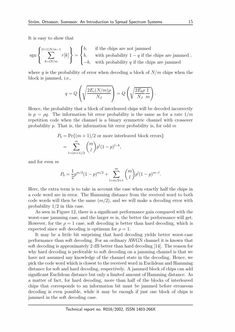
As seen in Figure 12, there is a significant performance gain compared with theworst-case jamming case, and the larger m is, the better the performance will get.However, for the ρ = 1 case, soft decoding is better than hard decoding, which isexpected since soft decoding is optimum for ρ = 1.
It may be a little bit surprising that hard decoding yields better worst-caseperformance than soft decoding. For an ordinary AWGN channel it is known thatsoft decoding is approximately 2 dB better than hard decoding [14]. The reason forwhy hard decoding is preferable to soft decoding on a jamming channel is that wehave not assumed any knowledge of the channel state in the decoding. Hence, wepick the code word which is closest to the received word in Euclidean and Hammingdistance for soft and hard decoding, respectively. A jammed block of chips can addsignificant Euclidean distance but only a limited amount of Hamming distance. Asa matter of fact, for hard decoding, more than half of the blocks of interleavedchips that corresponds to an information bit must be jammed before erroneousdecoding is even possible, while it may be enough if just one block of chips isjammed in the soft decoding case.
Technical report no. R016/2002, ISSN 1403-266X
16 Strom, Ottosson, Svensson: An Introduction to Spread Spectrum Systems
0 10 20 30 4010
−7
10−6
10−5
10−4
10−3
10−2
10−1
Diversity m = 3
Eb/N
J in dB
Pb
Worst−case ρ, no diversityBroadband jammer, no div.
0 10 20 30 4010
−7
10−6
10−5
10−4
10−3
10−2
10−1
Diversity m = 9
Eb/N
J in dB
Pb
Worst−case ρ, no diversityBroadband jammer, no div.
ρ = 1 0.1
0.01
ρ = 1
0.5
0.1
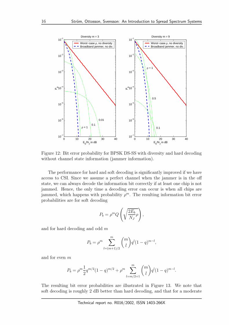
Figure 12: Bit error probability for BPSK DS-SS with diversity and hard decodingwithout channel state information (jammer information).
The performance for hard and soft decoding is significantly improved if we haveaccess to CSI. Since we assume a perfect channel when the jammer is in the offstate, we can always decode the information bit correctly if at least one chip is notjammed. Hence, the only time a decoding error can occur is when all chips arejammed, which happens with probability ρm. The resulting information bit errorprobabilities are for soft decoding
Pb = ρmQ
(√2Eb
NJ
ρ
),
and for hard decoding and odd m
Pb = ρmm∑
l=(m+1)/2
(m
l
)ql(1 − q)m−l,
and for even m
Pb = ρm 1
2qm/2(1 − q)m/2 + ρm
m∑l=m/2+1
(m
l
)ql(1 − q)m−l.
The resulting bit error probabilities are illustrated in Figure 13. We note thatsoft decoding is roughly 2 dB better than hard decoding, and that for a moderate
Technical report no. R016/2002, ISSN 1403-266X

Strom, Ottosson, Svensson: An Introduction to Spread Spectrum Systems 17
0 10 20 30 4010
−7
10−6
10−5
10−4
10−3
10−2
10−1
Soft decoding, diversity m = 9
Eb/N
J in dB
Pb
Worst−case ρ, no diversityBroadband jammer, no div.
0 10 20 30 4010
−7
10−6
10−5
10−4
10−3
10−2
10−1
Hard decoding, diversity m = 9
Eb/N
J in dB
Pb
Worst−case ρ, no diversityBroadband jammer, no div.
ρ = 1
0.5
0.3
ρ = 1
0.5
0.3
Figure 13: Bit error probability for BPSK DS-SS with diversity using soft andhard decoding with perfect channel state information (jammer information).
m, the worst-case duty cycle is ρ = 1 for most bit error probabilities of practicalinterest. Hence, the jammer is forced into becoming a broadband nonpulsed noisejammer and is thereby effectively defeated.
For the more realistic case when there is also white Gaussian noise added bythe channel in addition to the jamming, we need to modify the decoding strate-gies for known CSI. For instance, in the soft decoding case, we should preferablyuse maximum-ratio combining, that is the soft decisions on the non-jammed chipsshould be weighted by E
1/2c /N0 and the jammed chips by E
1/2c /(N0 + NJ). More-
over, for a fixed Eb/N0, the bit error curves will exhibit error floors, i.e., the curveswill approach an asymptotical bit error rate determined by Eb/N0 as Eb/NJ be-comes large (similar to the behavior illustrated in Figure 8).
To further improve the performance, we can use a better channel code thanthe implicit repetition code. Both block and convolutional codes are possiblecandidates; however, convolutional codes are usually the preferred choice if wewant to do soft decoding. In a practical setting, a spread spectrum system withspreading factor N can be achieved by cascading a rate 1/ncc convolutional codewith a rate 1/nrc repetition code, where N = ncc + nrc. The output from the lastencoder should then be scrambled by a pseudo-random sequence for the system tobe called a spread spectrum system.
Technical report no. R016/2002, ISSN 1403-266X

18 Strom, Ottosson, Svensson: An Introduction to Spread Spectrum Systems
3.6 Signal Space Interpretation
To reflect back on Section 2, we will now examine the basis used in DS-SS in moredetail.
For the case when the chip waveforms are rectangular, we can form a set oforthonormal basis functions as
φI,k(t) = ΠTc(t − kTc)
√2
Tccos(2πfct)
φQ,k(t) = ΠTc(t − kTc)
√2
Tcsin(2πfct)
k = 0, 1, . . . (2)
(The subscripts I and Q stand for inphase and quadrature phase, respectively.)The functions will not be strictly bandlimited, but if we allow for some spectralleakage outside the system bandwidth, we may set the chip rate to 1/Tc = Wss/2(the system bandwidth is then equal to the null-to-null bandwidth of the trans-mitted signal).
Now consider the case when we want to transmit a (long) packet of P bits withbit rate 1/Tb. We can find 2PTb/Tc basis functions of the form described in (2)that are confined to the time interval [0, PTb]. Hence, the number of basis functionavailable per transmitted bit is
Nd =2PTb
Tc
1
P= 2
Tb
Tc
.
It is this fact that allows for channel coding with very low code rates to be usedin DS-SS without loss of spectral efficiency.
The basis is illustrated in a time-frequency diagram as shown in Figure 14.Note that only one of the Nd possible linearly independent combinations of thebasis functions is actually used for transmitting a bit (assuming BPSK modula-tion). Exactly which linear combination is used depends on the code sequenceand changes from bit to bit. This is what signifies a spread spectrum system: thetransmission uses a small dimensional space which is hidden in a large dimensionalspace, and the transmission space is chosen in a way which is independent of thetransmitted data and appears random and time-varying to the jammer.
From Figure 14, we also see why a pulsed jammer is so effective against anoninterleaved DS-SS system. A certain information bit is concentrated to aninterval of Tb seconds along the time axis. The jammer can concentrate its powerto jam a subset of the transmitted bits by transmitting pulsed noise. The jammedbits are likely to be in error, and this will dominate the average bit error probability.The countermeasure is equally logical. By introducing interleaving, we scatter thechips over a wide time interval, and a pulsed jammer is unlikely to hit all chipscorresponding to an information bit. Diversity is therefore introduced, and theprobability of correct decoding is consequently increased (especially if the receiverhas access to reliable channel state information).
For the case when we have root raised cosine pulse shapes, a set of orthonormalfunctions can be formed as
φI,k(t) = xRRC(t − kTc)√
2 cos(2πfct)
φQ,k(t) = xRRC(t − kTc)√
2 sin(2πfct)k = 0, 1, . . . (3)
Technical report no. R016/2002, ISSN 1403-266X

Strom, Ottosson, Svensson: An Introduction to Spread Spectrum Systems 19
1 2 3 4ssW
4
b cT NT
N
�
�
cT
1 2 3 41 2 3 4
frequency
time
Nd-dimensional space.
2 bT
Figure 14: Time-frequency plot of basis used for DS-SS (only the positive frequen-cies are shown). The boxes with the same background pattern are used for thesame bit. Note that this figure shows the noninterleaved case.
where xRRC(t) is a pulse with a root raised cosine spectrum with roll-off factor αand fc is the carrier frequency (located in the middle of the system bandwidth).The spectrum of the basis functions will span the entire system bandwidth if
1 + α
Tc= Wss.
Since xRRC(t) has infinite extension in time, we have to truncate the pulses in apractical implementation. If the pulse after truncation is sufficiently long, we willnot lose too much of the spectral compactness and we may still regard the pulsesas bandlimited to the system bandwidth.
Now consider the case when we want to transmit a (long) packet of P bits withbit rate 1/Tb. Ignoring the edge effects due to that the pulses have longer extensionthan Tc seconds and letting α be very small, we can find 2PTb/Tc basis functionsof the form described in (3). Hence, the number of basis function available pertransmitted bit is
Nd =2PTb
Tc
1
P= 2
Tb
Tc,
which is the same as in the rectangular chip waveform case.
4 Frequency-Hopping Spread Spectrum
The basis functions used in the DS case are designed to be time-limited and tospan the entire frequency band. The larger the system bandwidth, the shorter thepulses must be. Hence, for DS spread spectrum, Wss is limited to few hundredMHz due to hardware constraints. This implies that the processing gain is alsolimited. Moreover, the system bandwidth must be contiguous.
Technical report no. R016/2002, ISSN 1403-266X

20 Strom, Ottosson, Svensson: An Introduction to Spread Spectrum Systems
Both these limitations can be avoided by using a frequency-hopped spreadspectrum (FH-SS) system. If we let the baseband signal be denoted by x(t), thetransmitted signal in a FH-SS system is
s(t) = x(t)√
2 cos(2πfkt + θk), kTh ≤ t < (k + 1)Th
where 1/Th is the frequency hopping rate and fk and θk is the carrier frequencyand phase after the kth hop. The reason for including a carrier phase is that itmay be difficult to implement a system with continuous carrier phase. As we willsee, it is important that the hopping rate is relatively high, and it may therefore bedifficult for the receiver to estimate the carrier phase, and noncoherent methods aretherefore widely used. In the following, we will assume that M-ary frequency-shiftkeying (FSK) is used, and that the frequency spacing will allow for noncoherentdetection.
A system can be either fast hopping or slow hopping. The system is said tobe fast hopping if the frequency hop rate is larger than the symbol rate, i.e., if1/Th > 1/Ts, where 1/Ts is the symbol rate. Logically, a system is said to beslow hopping if 1/Th ≤ 1/Ts. We should here interpret 1/Ts as the rate of thepossibly coded symbols. For an uncoded system, the symbol rate is log2(M)/Tb
where 1/Tb is the information bit rate, while for a system which employs a rate Rc
error-control code, the symbol rate is log2(M)/(RcTb).For a slow hopping system, the frequency spacing between the signal alterna-
tives must be a multiple of 1/Ts to allow for noncoherent detection (we want thesignal alternatives to be orthogonal, regardless of the carrier phase). However, ifthe system is fast hopping, a symbol will span more than one hop, and we must en-sure that the partial symbols within a hop are orthogonal (regardless of the carrierphase). Hence, the signal alternatives must be spaced by a multiple of 1/Th.
To account for both fast and slow hopping systems, we define the chip rate asthe maximum rate with which the transmitted signal can change frequency, i.e.,
1
Tc
= max
{1
Th
,1
Ts
}.
The chip rate will decide the minimum frequency spacing between the signal al-ternatives as ∆f = 1/Tc.
For slow hopping systems, we must therefore change the subcarrier spacingwhen introducing coding (assuming constant M and information bit rate). De-pending on the code, symbol, and hop rates, this may or may not be necessary forfast hopping systems.
To summarize, we construct the transmitted signal from orthonormal functionsfrom the set
φk,l(t) = ΠTc(t − kTc)
√2
Tccos(2π[f0 + l∆f ]t + θk), (4)
where k is the hop index, l = 0, 1, . . . , Nf − 1 is the subcarrier index, Nf is thetotal number of subcarriers, and θk is the carrier phase after hop k (assumed tobe unknown to the receiver). If we ignore the spectral leakage due to the use
Technical report no. R016/2002, ISSN 1403-266X

Strom, Ottosson, Svensson: An Introduction to Spread Spectrum Systems 21
of rectangular pulses, the number of subcarriers is Nf = WssTc. We have hereassumed that the system bandwidth is contiguous, but we can easily redistributethe subcarriers to allow for a noncontiguous system bandwidth. Furthermore, sincethe fundamental pulse length, Tc, is not directly coupled to Wss, we can allow forvery large processing gains with reasonable hardware complexity.
There exist many ways to compile a transmitted signal from the functionsin (4). We can let the M frequencies (corresponding to one symbol) to be adjacentor nonadjacent, and we can let the carrier frequency jump a multiple of M∆f orto any subcarrier (or perhaps even to any frequency in the system bandwidth).Which method to use depends on which hardware complexity we can afford. Theleast structure in the transmitted signal is clearly when we allow any subcarrier tobe transmitted in any given hop. However, this will also require the most complexhardware.
Time-frequency plots for a fast hopping and a slow hopping FH-SS system areshown in Figure 15. In both plots, M = 4 adjacent subcarriers are used as signalalternatives in a 4-ary FSK constellation, and any subcarrier can be the maincarrier. In the fast hopping system (the plot to the left), a symbol is split overtwo hops, and in the slow hopping system, two symbols are transmitted per hop.
1
sTc hT T�
frequency
time2 sT
2
3
4
5
6
7
0c
M
T 1
2
3
4
5
6
7
0
1
2
3
4
5
6
7
0
1
2
3
4
5
6
7
0
1
hTc sT T�
frequency
time2 hT
2
3
4
5
6
7
0c
M
T 1
2
3
4
5
6
7
0
1
2
3
4
5
6
7
0
1
2
3
4
5
6
7
0
1f
cT� �
Slow HoppingFast Hopping
Figure 15: Time-frequency plot of FH-SS (only the positive frequencies are shown)with 4-ary FSK modulation. The boxes with the same background pattern are usedfor the same symbol.
4.1 Broadband Noise Jamming
Again, the most benign form of jamming is broadband nonpulsed noise jamming.For uncoded binary FSK with noncoherent detection, the resulting bit error prob-ability is
Pb =1
2e− Eb
2NJ ,
where NJ = J/Wss.
Technical report no. R016/2002, ISSN 1403-266X

22 Strom, Ottosson, Svensson: An Introduction to Spread Spectrum Systems
4.2 Partial-Band Noise Jamming
Compared to broadband noise jamming, the performance for the uncoded systembecomes much worse for pulsed broadband noise jamming or nonpulsed partial-band noise jamming. The reason is the same as for the DS case: when the jammercan concentrate its power to affect a fraction of the transmitted symbols, thejammed symbols will be erroneously decoded with a high probability, and thisconditional error probability will dominate the average error probability. Just asin the DS case, we can affect certain symbols by pulsing the jammer along the timeaxis. However, we can also “pulse” the jammer along the frequency axis. This iscalled partial-band jamming.
A jammer that uses partial-band noise jamming will concentrate its power toa bandwidth ρWss, where ρ is the frequency domain duty cycle (0 < ρ ≤ 1). Thejammer signal is Gaussian noise with a flat power spectral density over the jammedbandwidth, i.e., in the jammed band the power spectral density is
J
2Wssρ=
NJ
2ρ
If we assume that the jammed bandwidth is placed such that all signal alternatives(subcarriers) used for a certain symbol are either jammed or not jammed, thenthe probability that a certain symbol will be jammed is ρ. The resulting bit errorprobability for BFSK with noncoherent detection is then
Pb = (1 − ρ) × 0 + ρ1
2exp
(−Ebρ
2NJ
)=
ρ
2exp
(−Ebρ
2NJ
).
The worst-case duty cycle is easily found to be
ρwc =
{2
Eb/NJ, Eb/NJ > 2
1, Eb/NJ ≤ 2,
and the worst-case bit error probability is
Pb,wc =
{1
eEb/NJ, Eb/NJ > 2
ρ2exp
(− Ebρ
2NJ
), Eb/NJ ≤ 2
.
We note that, just as for the case of DS-SS with worst-case pulsed broadbandnoise jamming, the error probability is made inversely proportional to Eb/NJ forsufficiently large Eb/NJ . This is a significant degradation from the broadbandnoise jamming case, for which the error probability falls of exponentially withEb/NJ .
4.3 Multitone Jamming
An efficient jamming method for FH-SS is multitone jamming. Recall the numberof subcarriers is Nf = WssTc. A jammer (which is assumed to have knowledgeof where the subcarriers are located) can choose to jam certain subcarriers by
Technical report no. R016/2002, ISSN 1403-266X

Strom, Ottosson, Svensson: An Introduction to Spread Spectrum Systems 23
transmitting pure tones at the selected subcarriers. To describe the worst-casejamming strategy, i.e., how the jammer should choose which subcarriers to jamand how to assign the power to each jammer tone, is actually rather involved.The reader is referred to [4] for a detailed discussion on this. In short, it is shownin [4] that a simple but effective jamming strategy is to randomly select whichsubcarriers to jam, and to assign a power to each jamming tone which is slightlylarger than the power of the received information tone. This strategy, knownas independent multitone jamming, is more harmful than worst-case partial-bandnoise jamming.
A more complicated jamming strategy, which under some circumstances ismore effective than independent multitone jamming, is called band multitone jam-ming. Band multitone jamming can be used if the jammer knows exactly how thetransmitter partitions the Nf possible subcarriers into bands of M subcarriers fortransmission of a symbol. Note that this is not the same as that the jammer knowswhich band is used during a certain symbol interval; the jammer only knows towhat band any subcarrier belongs. The jammer can now choose to jam exactlyn or none of the subcarriers in a band. This means that the jammer either jamsa band or not, and if the band is jammed, exactly n of the M subcarriers arejammed in that band (0 < n ≤ M).
4.4 Repetition Coding and Interleaving
To combat partial-band or multitone jamming, we can use channel coding andinterleaving to spread the information bits over several transmissions. With theappropriate decoding strategy, we can gain back most or all of the performanceloss from broadband noise jamming to partial-band or multitone jamming. Thedetails on how to form the decision metric and the resulting performance is a bitinvolved and will be excluded here. Again, the interested reader is referred to [4]for a detailed discussion.
5 Commercial Spread Spectrum Systems
As mentioned earlier, the number of nonmilitary spread spectrum systems haveincreased rapidly the last decades. The applications are quite diverse: underwatercommunications [15], wireless local loop systems [16], wireless local area networks,cellular systems, satellite communications [17], and ultra wideband systems [18].Spread spectrum is also used in wired application in, e.g., power-line communica-tion [19] and have been proposed for communication over cable-TV networks [16]and optical fiber systems [20, 21]. Finally, spread spectrum techniques have beenfound to be useful in ranging, e.g., radar and navigation, e.g., the Global Position-ing System (GPS) [22]. Other applications are watermarking of multimedia [23]and (mentioned here as a curiosity) in clocking of high-speed electronics [24, 25].Due to space constraint, we will only briefly mention some of the hot wirelessapplications here.
The wireless local area network (WLAN) standard IEEE 802.11 was originallydesigned to operate in the ISM band at approximately 2.4 GHz. The standard
Technical report no. R016/2002, ISSN 1403-266X

24 Strom, Ottosson, Svensson: An Introduction to Spread Spectrum Systems
supports several different coding and modulation formats and several data rates.The first version of the standard was released in 1997 and supports both FH andDS spread spectrum formats with data rates of 1 or 2 Mbit/s [26]. The FH modesare slow hopping and use so-called Gaussian FSK (GFSK) modulation (binaryfor 1 Mbit/s and 4-ary for 2 Mbit/s). The system hops over 79 subcarriers with1 MHz spacing. The DS-SS modes use a 11-chip long Barker sequence which isperiodically repeated for each symbol. The chip rate is 11 Mchips/s, and thesymbol rate is 1 Msymbols/s. The modulation is differentially encoded BPSK orQPSK (for 1 and 2 Mbit/s, respectively). We note that the processing gain israther low, especially for the DS-SS modes.
The 802.11 standard has since 1997 been extended in several directions (newbands, higher data rates, etc). In 1999, the standard was updated to IEEE 802.11b(also known as Wi-Fi, if the equipment also passes an interoperability test). Inaddition to the original 1 and 2 Mbit/s modes, IEEE 802.11b also supports 5.5and 11 Mbit/s DS-SS modes [27] and several other optional modes with varyingrates. The higher rate DS-SS modes uses so-called complementary code keying(CCK). The chip rate is still 11 Mchips/s and each symbol is represented by 8complex chips. Hence, for the 5.5 Mbit/s mode, each symbol carries 4 bits, andfor the 11 Mbit/s mode, each symbol carries 8 bits. Hence, the processing gains isreduced compared to the 1 and 2 Mbit/s modes. As a matter of fact, the 11 Mbit/sis perhaps not even a spread-spectrum system. The CCK modulation is a little bitcomplicated to describe, but in essence it forms the complex chips by combininga block code and differential QPSK [26, Section 18.4.6.5].
Bluetooth is primarily a cable replacement system, i.e., a system for short rangecommunication with relatively low data rate. It is designed for the ISM band anduses slow hopping FH-SS with GFSK modulation (BT = 0.5 and modulationindex between 0.28 and 0.35). The systems hops over 79 subcarriers with a rateof 1600 hops/s. The subcarrier spacing is 1 MHz, and in most countries thesubcarriers are placed at fk = 2402 + k MHz for k = 0, 1, . . . , 78. Bluetoothsupports both synchronous and asynchronous links and several different codingand packet schemes. The user data rates varies from 64 kbits/s (symmetrical andsynchronous) to 723 kbits/s (asymmetrical and asynchronous). The maximumsymmetrical rate is 434 kbits/s. The range of the system is quite short, probablyless than 10 m in most environments. It is likely that future versions of Bluetoothwill support higher data rates and longer ranges.
The first cellular system with a distinct spread spectrum component was IS-95 (also known as cdmaOne or somewhat pretentiously as CDMA). Although theGlobal System for Mobile Communications (GSM), has a provision for frequencyhopping, it is not usually considered to be a spread spectrum system. Often,spread spectrum and code-division multiple access (CDMA) are used as synonyms,although they really are not. A multiple access method is a method for allowingseveral links (that are not at the same geographical location) to share a commoncommunication resource. CDMA is a multiple access method where the links arespread spectrum links. A receiver that is tuned to a certain user relies on the anti-jamming properties of the spread spectrum format to suppress the other users’signals.
Technical report no. R016/2002, ISSN 1403-266X

Strom, Ottosson, Svensson: An Introduction to Spread Spectrum Systems 25
IS-95 uses DS-SS links with a chip rate of 1.2288 Mchips/s and a bandwidthof (approximately) 1.25 MHz. In the downlink (forward link or base-station-to-terminal link) the chips are formed by a combination of convolutional encoding,repetition encoding, and scrambling. The chips are transmitted both in inphaseand quadrature (but scrambled by different PN sequences). In the uplink (reverselink), the transmitted chips are formed by a combination of convolutional cod-ing, orthogonal block coding, repetition coding, and scrambling. In the originalIS-95 (IS-95A), the uplink was designed such that the detection could be donenoncoherently. In the third generation evolution of IS-95, known as cdma2000,the modulation and coding has changed and the transmitted bandwidth tripled toallow for peak data rates exceeding 2 Mbit/s [28, 29, 30].
Another third generation system is Wideband CDMA (WCDMA) [31]. WCDMAis a rather complex system with many options and modes. We will here only brieflydescribe the frequency-division duplex (FDD) mode. The FDD mode uses direct-sequence spreading with a chip rate of 3.84 Mchips/s. The chip waveform is a root-raised cosine pulse with roll-off factor 0.22, and the bandwidth of the transmittedsignal is approximately 5 MHz. WCDMA supports many different information bitrates by changing the spreading factor (from 4 to 256 in the uplink and from 4 to512 in the downlink) and the error control scheme (no coding, convolutional cod-ing, or turbo coding); however, the modulation is QPSK with coherent detectionin all cases. Today, the maximum information data rate is roughly 2 Mbits/s, butit is likely that future revisions of the standard will support higher rates throughnew combinations of spreading, coding, and modulation.
Technical report no. R016/2002, ISSN 1403-266X
26 Strom, Ottosson, Svensson: An Introduction to Spread Spectrum Systems
References
[1] Robert A. Scholtz. “The origins of spread-spectrum communications.” IEEETransactions on Communications, vol. 30, no. 5, pp. 822–854, May 1982.(Part I).
[2] Robert A. Scholtz. “Notes on spread-spectrum history.” IEEE Transactionson Communications, vol. 31, no. 1, pp. 82–84, January 1983.
[3] R. Price. “Further notes and anecdotes on spread-spectrum origins.” IEEETransactions on Communications, vol. 31, no. 1, pp. 85–97, January 1983.
[4] Marvin K. Simon, Jim K. Omura, Robert A. Scholtz, and Barry K. Levitt.Spread Spectrum Communications Handbook. McGraw-Hill, revised editionedition, 1994.
[5] Roger L. Peterson, Rodger E. Ziemer, and David E. Borth. Introduction toSpread Spectrum Communications. Prentice Hall, 1995.
[6] Robert C. Dixon. Spread Spectrum Systems with Commercial Applications.John Wiley and Sons, third edition, 1994.
[7] Raymond L. Pickholtz, Donald L. Schilling, and Laurence B. Milstein. “The-ory of spread-spectrum communications—A tutorial.” IEEE Transactions onCommunications, vol. 30, no. 5, pp. 855–884, May 1982.
[8] Henry J. Landau and Henry O. Pollak. “Prolate spherodial wave functions,Fourier analysis, and uncertainty, Part II.” Bell Systems Technical Journal,vol. 40, no. 1, pp. 65–84, January 1961.
[9] Henry J. Landau and Henry O. Pollak. “Prolate spherodial wave functions,Fourier analysis, and uncertainty, Part III, The dimension of the space ofessentially time- and band-limited signals.” Bell Systems Technical Journal,vol. 41, pp. 1295–1336, July 1962.
[10] David Slepian. “On bandwidth.” IEEE Proceedings, vol. 64, no. 4, pp. 292–300, 1976.
[11] David Slepian. “Some comments on Fourier analysis, uncertainty and model-ing.” SIAM Review, vol. 25, no. 3, pp. 379–393, July 1983.
[12] James L. Massey. “Information theory aspects of spread-spectrum communi-cations.” In Proceedings of IEEE International Symposium on Spread Spec-trum Techniques and Applications, pp. 16–21. 1994.
[13] Dilip V. Sarwate and Michael B. Pursley. “Crosscorrelation properties ofpseudorandom and related sequences.” Proceedings of the IEEE, vol. 68, no. 5,pp. 593–619, May 1980.
[14] John G. Proakis. Digital Communications. McGraw-Hill, fourth edition, 2000.
Technical report no. R016/2002, ISSN 1403-266X
Strom, Ottosson, Svensson: An Introduction to Spread Spectrum Systems 27
[15] Charalampos C. Tsimenidis, Oliver R. Hinton, Alan E. Adams, and Bayan S.Sharif. “Underwater acoustic receiver employing direct-sequence spread spec-trum and spatial diversity combining for shallow-water multiaccess network-ing.” IEEE Journal of Oceanic Engineering, vol. 26, no. 4, pp. 594–603,October 2001.
[16] D. Thomas Magill. “Spread spectrum techniques and applications in Amer-ica.” In Proceedings of International Symposium on Spread Spectrum Tech-niques and Applications, pp. 1–4. 1995.
[17] D. Thomas Magill, Francis D. Natali, and Gwyn P. Edwards. “Spread-spectrum technology for commercial applications.” Proceedings of the IEEE,vol. 82, no. 4, pp. 572–584, April 1994.
[18] Moe Z. Win and Robert A. Scholtz. “Ultra-wide bandwidth time-hoppingspread-spectrum impulse radio for wireless multiple-access communications.”IEEE Transactions on Communications, vol. 48, no. 4, pp. 679–691, April2000.
[19] Denny Radford. “Spread spectrum data leap through AC power wiring.”IEEE Spectrum, vol. 33, no. 11, pp. 48–53, November 1996.
[20] Jawad A. Salehi. “Code divsion multiple-access techniques in optical fibernetworks—Part I: fundamental principles.” IEEE Transaction on Communi-cations, vol. 37, no. 8, pp. 824–833, August 1989.
[21] Jawad A. Salehi and Charles A. Brackett. “Code divsion multiple-accesstechniques in optical fiber networks—Part II: systems performance analysis.”IEEE Transaction on Communications, vol. 37, no. 8, pp. 834–842, August1989.
[22] Micheal S. Braasch and A. J. van Dierendonck. “GPS receiver architecturesand measurements.” Proceedings of the IEEE, vol. 87, no. 1, pp. 48–64, Jan-uary 1999.
[23] Ingemar J. Cox, Joe Kilian, F. Thomson Leighton, and Talal Shamoon. “Se-cure spread spectrum watermarking for multimedia.” IEEE Transactions onImage Processing, vol. 6, no. 12, pp. 1673–1687, December 1997.
[24] Harry G. Skinner and Kevin P. Slattery. “Why spread spectrum clockingof computing devices is not cheating.” In Proceedings 2001 InternationalSymposium on Electromagnetic Compatibility, pp. 537–540. August 2001.
[25] S. Gardiner, K. Hardin, J. Fessler, and K. Hall. “An introduction tospread spectrum clock generation for EMI reduction.” Electronic Engineering,vol. 71, no. 867, pp. 75, 77, 79, 81, April 1999.
[26] “IEEE standard for information technology- telecommunications and informa-tion exchange between systems-local and metropolitan area networks-specific
Technical report no. R016/2002, ISSN 1403-266X

28 Strom, Ottosson, Svensson: An Introduction to Spread Spectrum Systems
requirements-part 11: Wireless LAN medium access control (MAC) and physi-cal layer (PHY) specifications.” IEEE Std 802.11-1997, November 1997. ISBN:1-55937-935-9.
[27] “Supplement to IEEE standard for information technology- telecommunica-tions and information exchange between systems- local and metropolitan areanetworks- specific requirements- part 11: Wireless LAN medium access con-trol (MAC) and physical layer (PHY) specifications: Higher-speed physicallayer extension in the 2.4 GHz band.” IEEE Std 802.11b-1999, January 2000.ISBN: 0-7381-1811-7.
[28] Daisuke Terasawa and Jr. Edward G. Tiedemann. “cdmaOne (IS-95) technol-ogy overview and evolution.” In Proceedings IEEE Radio Frequency IntegratedCircuits (RFIC) Symposium, pp. 213–216. June 1999.
[29] Douglas N. Knisely, Sarath Kumar, Subhasis Laha, and Sanjiv Nanda. “Evo-lution of wireless data services: IS-95 to cdma2000.” IEEE CommunicationsMagazine, vol. 36, no. 10, pp. 140–149, October 1998.
[30] Theodore S. Rappaport. Wireless Communications: Principles and Practice.Prentice Hall, second edition, 2001.
[31] “3rd generation partnership project; technical specification group radio accessnetwork; physical layer - general description (release 4), 3GPP TS 25.201V4.1.0 (2001-12).” On-line: http://www.3gpp.org. Accessed March 20, 2002.
Technical report no. R016/2002, ISSN 1403-266X


An Introduction to Spread Spectrum Systemsc© Erik G. Strom, Tony Ottosson, and Arne Svensson, 2002
Technical report No. R016/2002ISSN 1403-266XCommunication Systems GroupDept. of Signals and SystemsChalmers University of TechnologySE-412 96 GoteborgSwedenTelephone +46 (0)31–772 1000