Embed Size (px)
Citation preview
An Approved Continuing Education Provider
PDH Course C645 (2 PDH)
An Introduction to Retaining Walls and
Excavation Support Structures
J. Paul Guyer, P.E., R.A.
2013
PDH Online | PDH Center
5272 Meadow Estates Drive
Fairfax, VA 22030-6658
Phone & Fax: 703-988-0088
www.PDHonline.org
www.PDHcenter.com
www.PDHcenter.com PDH Course C645 www.PDHonline.org
© J. Paul Guyer 2013 Page 2 of 32
An Introduction to Retaining Walls and Excavation
Support Structures
J. Paul Guyer, P.E., R.A.
CONTENTS
1. DESIGN CONSIDERATIONS FOR RETAINING WALLS
2. EARTH PRESSURES
3. EQUIVALENT FLUID PRESSURES
4. DESIGN PROCEDURES FOR RETAINING WALLS
5. CRIB WALL
6. EXCAVATION SUPPORT SYSTEMS
7. STRUTTED EXCAVATIONS
8. STABILITY OF BOTTOM OF EXCAVATION
9. ANCHORED WALLS
(This publication is adapted from the Unified Facilities Criteria of the United States government which are in the public domain, have been authorized for unlimited distribution, and are not copyrighted.) (The figures, tables and formulas in this publication may at times be a little difficult to read, but they are the best available. DO NOT PURCHASE THIS PUBLICATION IF THIS LIMITATION IS NOT ACCEPTABLE TO YOU.)
www.PDHcenter.com PDH Course C645 www.PDHonline.org
© J. Paul Guyer 2013 Page 3 of 32
1. DESIGN CONSIDERATIONS FOR RETAINING WALLS.
1.1 GENERAL. Retaining walls must be designed so that foundation pressures do not
exceed allowable bearing pressures, wall settlements are tolerable, safety factors
against sliding and overturning are adequate, and the wall possesses adequate
structural strength. Methods for evaluating earth pressures on retaining walls and
design procedures are summarized herein for cohesionless backfill materials, which
should be used whenever practicable.
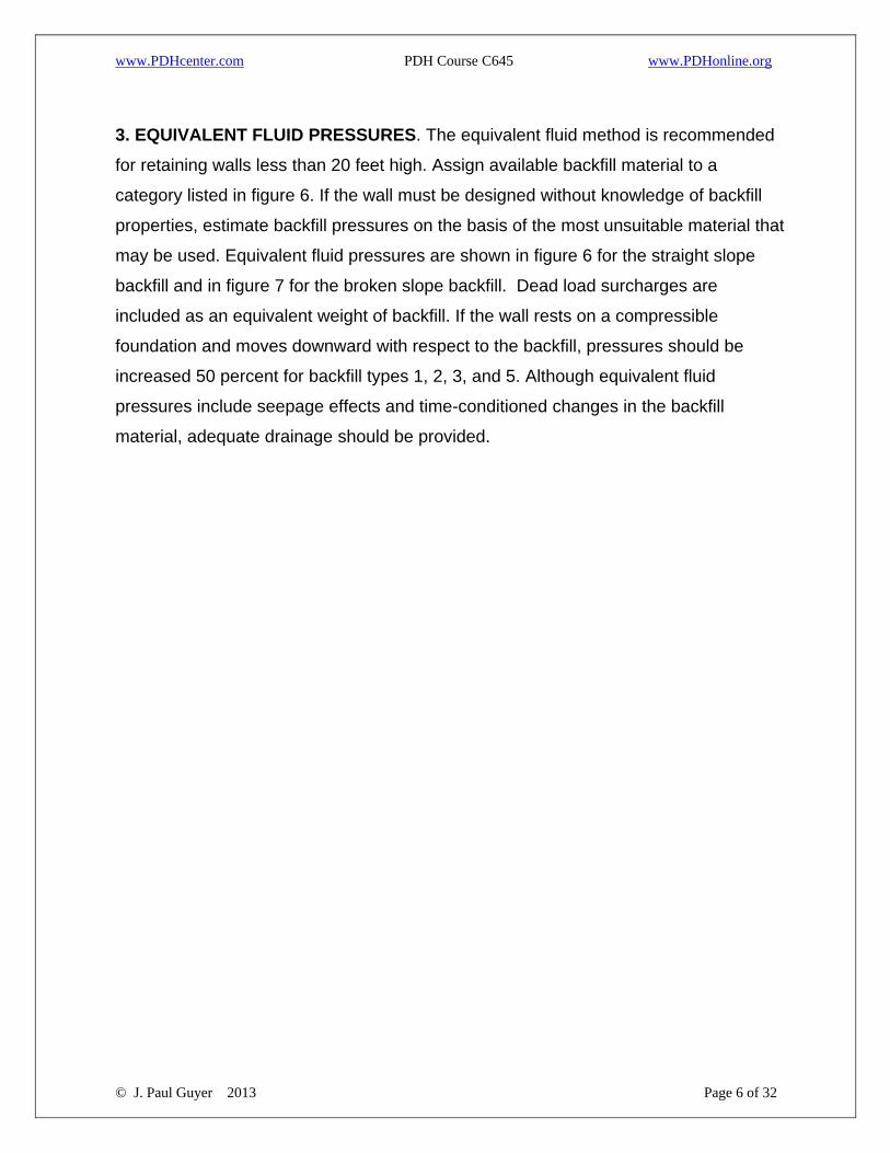
1.2 FORCES ACTING ON RETAINING WALLS. Forces include earth pressures,
seepage and uplift pressures, surcharge loads, and weight of the wall. Typical load
diagrams for principal wall types are shown in figure 1. The magnitude and distribution
of active and passive earth pressures are developed from the earth theory for walls
over 20 feet high and from semi-empirical curves for lower walls. The subgrade
reaction along the base is assumed linearly distributed.

www.PDHcenter.com PDH Course C645 www.PDHonline.org
© J. Paul Guyer 2013 Page 4 of 32
2. EARTH PRESSURES.
2.1 EARTH PRESSURE AT REST. For cohesionless soils, with a horizontal surface,
determine the coefficient of earth pressure at rest, K0, from the following:
K0 = 1 - sin Φ (eq 1)
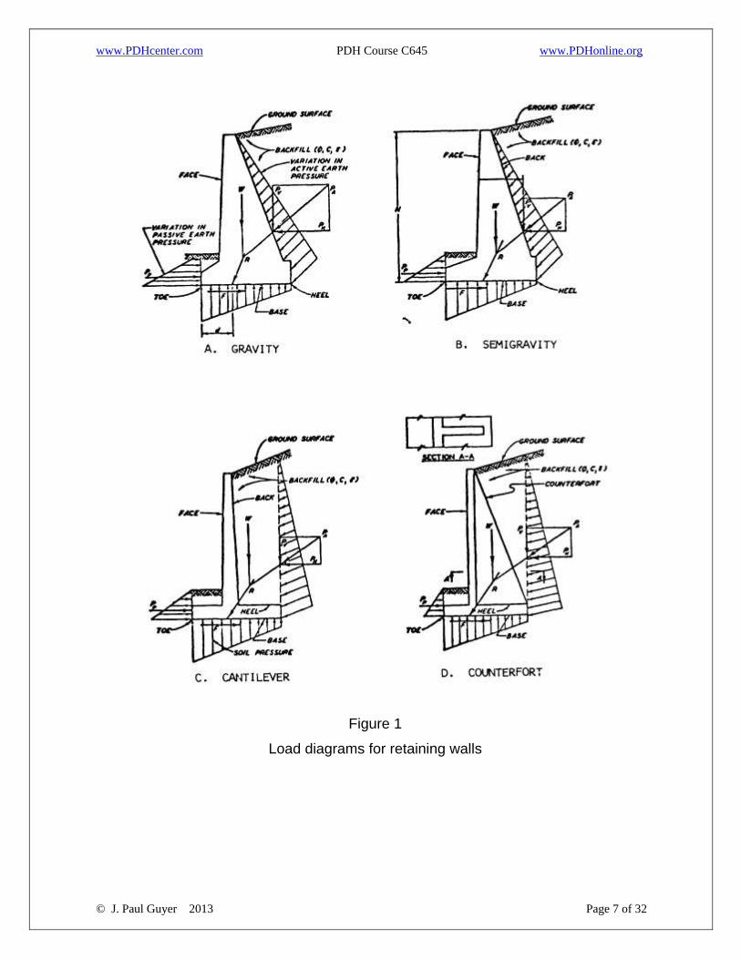
2.2 ACTIVE EARTH PRESSURE. Formulas for calculating the coefficient of active
earth pressure for a cohesionless soil with planar boundaries are presented in figure 2.
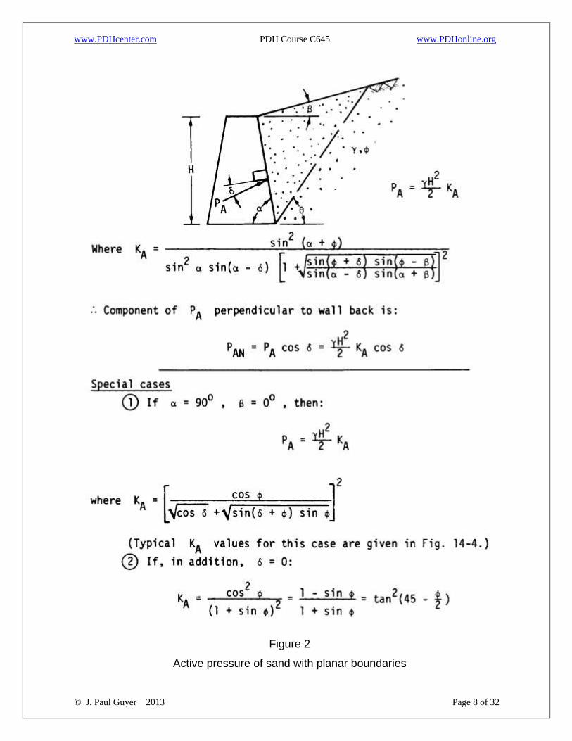
2.3 PASSIVE EARTH PRESSURE. Formulas for calculating the coefficient of
passive earth pressure for a cohesionless soil with planar boundaries are presented in
figure 3.
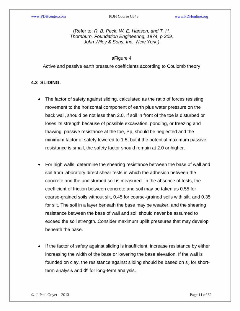
2.4 EARTH PRESSURE CHARTS. Earth pressure coefficients based on planar
sliding surfaces are presented in figure 4. The assumption of a planar sliding surface is
sufficiently accurate for the majority of practical problems. A logarithmic spiral failure
surface should be assumed when passive earth pressure is calculated and the angle
of wall friction, δ, exceeds Φ’ /3. Earth pressure coefficients based on a logarithmic
spiral sliding surface are presented in textbooks on geotechnical engineering. Passive
pressure should not be based on Coulomb theory since it overestimates passive
resistance. Because small movements mobilize δ and concrete walls are relatively
rough, the wall friction can be considered when estimating earth pressures. In general,
values of d for active earth pressures should not exceed θ’/2 and for passive earth
pressures should not exceed θ’/3. The angle of wall friction for walls subjected to
vibration should be assumed to be zero.
2.5 DISTRIBUTION OF EARTH PRESSURE. A presentation of detailed analyses is
beyond the scope of this manual. However, it is sufficiently accurate to assume the
following locations of the earth pressure resultant:
www.PDHcenter.com PDH Course C645 www.PDHonline.org
© J. Paul Guyer 2013 Page 5 of 32
2.5.1 FOR WALLS ON ROCK:
0.38H above base for horizontal or downward sloping backfill
0.45H above base for upward sloping backfill
2.5.2 FOR WALLS ON SOIL:
0.33H above base of horizontal backfill
0.38H above base of upward sloping backfill
Water pressures are handled separately.
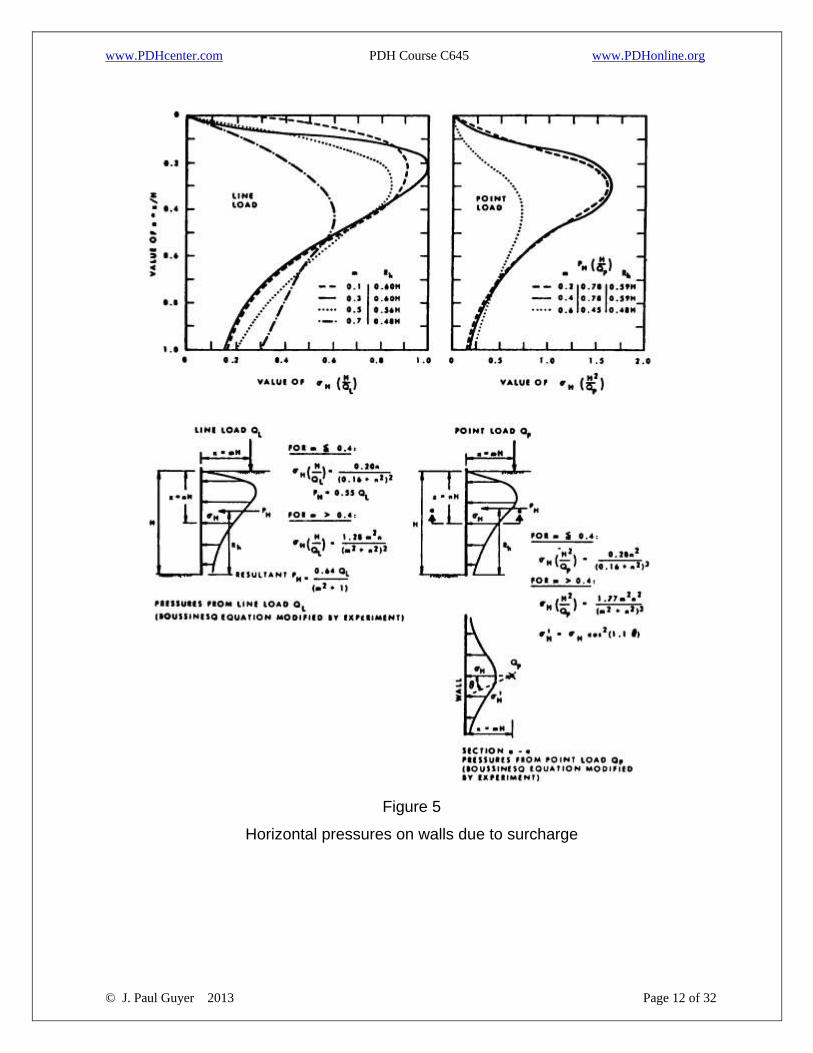
2.6 SURCHARGE LOADS. Equations for concentrated point and line load are
presented in figure 5. For uniform or non-uniform surcharge pressure acting on an
irregular area, use influence charts based on the Boussinesq equations for horizontal
loads and double the horizontal pressures obtained.
2.7 DYNAMIC LOADS. The effects of dynamic loading on earth pressures are
beyond the scope of this publication. Refer to geotechnical engineering textbooks
dealing with the subject.
www.PDHcenter.com PDH Course C645 www.PDHonline.org
© J. Paul Guyer 2013 Page 6 of 32
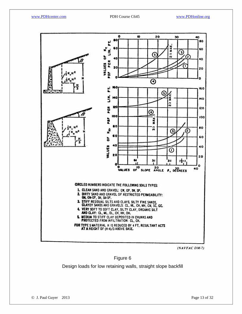
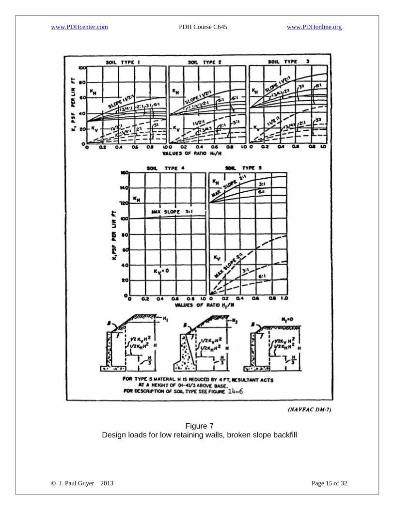
3. EQUIVALENT FLUID PRESSURES. The equivalent fluid method is recommended
for retaining walls less than 20 feet high. Assign available backfill material to a
category listed in figure 6. If the wall must be designed without knowledge of backfill
properties, estimate backfill pressures on the basis of the most unsuitable material that
may be used. Equivalent fluid pressures are shown in figure 6 for the straight slope
backfill and in figure 7 for the broken slope backfill. Dead load surcharges are
included as an equivalent weight of backfill. If the wall rests on a compressible
foundation and moves downward with respect to the backfill, pressures should be
increased 50 percent for backfill types 1, 2, 3, and 5. Although equivalent fluid
pressures include seepage effects and time-conditioned changes in the backfill
material, adequate drainage should be provided.
www.PDHcenter.com PDH Course C645 www.PDHonline.org
© J. Paul Guyer 2013 Page 7 of 32
Figure 1
Load diagrams for retaining walls
www.PDHcenter.com PDH Course C645 www.PDHonline.org
© J. Paul Guyer 2013 Page 8 of 32
Figure 2
Active pressure of sand with planar boundaries
www.PDHcenter.com PDH Course C645 www.PDHonline.org
© J. Paul Guyer 2013 Page 9 of 32
Figure 3
Passive pressure of sand with planar boundaries
www.PDHcenter.com PDH Course C645 www.PDHonline.org
© J. Paul Guyer 2013 Page 10 of 32
4. DESIGN PROCEDURES FOR RETAINING WALLS. 4.1 CRITERIA FOR SELECTING EARTH PRESSURES.
The equivalent fluid method should be used for estimating active earth
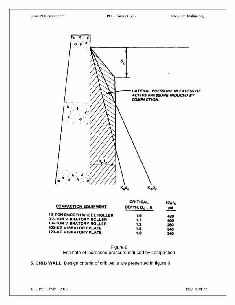
pressures on retaining structures up to 20 feet high, with the addition to earth
pressures resulting from backfill compaction (fig 8).
For walls higher than 20 feet, charts, equations, or graphical solutions should
be used for computing lateral earth pressures, with the addition of earth
pressures resulting from backfill compaction.
Use at-rest pressures for rigid retaining structures resting on rock or batter
piles. Design cantilever walls founded on rock or restrained from lateral
movement for at-rest pressures near the base of the wall, active pressures
along the upper portions of the wall, and compaction-induced earth pressures
from the top to the depth at which they no longer increase lateral earth
pressures (fig 8/14-8). Generally, a linear variation in earth pressure coefficients
with depth may be assumed between the sections of wall.
Consider passive pressures in the design if applied loads force the structure to
move against the soil. Passive pressures in front of retaining walls are partially
effective in resisting horizontal sliding.
4.2 OVERTURNING. Calculate the factor of safety, FS, against overturning, defined
as the ratio of resisting moments to the overturning moments. Calculate the resultant
force using load diagrams shown in figure 1, as well as other loadings that may be
applicable. Use only half of the ultimate passive resistance in calculating the safety
factor. The resultant of all forces acting on the retaining wall should fall within the
middle third to provide a safety factor with respect to overturning equal to or greater
than 1.5.
www.PDHcenter.com PDH Course C645 www.PDHonline.org
© J. Paul Guyer 2013 Page 11 of 32
(Refer to: R. B. Peck, W. E. Hanson, and T. H. Thornburn, Foundation Engineering, 1974, p 309,
John Wiley & Sons. Inc., New York.)
aFigure 4
Active and passive earth pressure coefficients according to Coulomb theory
4.3 SLIDING.
The factor of safety against sliding, calculated as the ratio of forces resisting
movement to the horizontal component of earth plus water pressure on the
back wall, should be not less than 2.0. If soil in front of the toe is disturbed or
loses its strength because of possible excavation, ponding, or freezing and
thawing, passive resistance at the toe, Pp, should be neglected and the
minimum factor of safety lowered to 1.5; but if the potential maximum passive
resistance is small, the safety factor should remain at 2.0 or higher.
For high walls, determine the shearing resistance between the base of wall and
soil from laboratory direct shear tests in which the adhesion between the
concrete and the undisturbed soil is measured. In the absence of tests, the
coefficient of friction between concrete and soil may be taken as 0.55 for
coarse-grained soils without silt, 0.45 for coarse-grained soils with silt, and 0.35
for silt. The soil in a layer beneath the base may be weaker, and the shearing
resistance between the base of wall and soil should never be assumed to
exceed the soil strength. Consider maximum uplift pressures that may develop
beneath the base.
If the factor of safety against sliding is insufficient, increase resistance by either
increasing the width of the base or lowering the base elevation. If the wall is
founded on clay, the resistance against sliding should be based on su for short-
term analysis and Φ’ for long-term analysis.
www.PDHcenter.com PDH Course C645 www.PDHonline.org
© J. Paul Guyer 2013 Page 12 of 32
Figure 5
Horizontal pressures on walls due to surcharge
www.PDHcenter.com PDH Course C645 www.PDHonline.org
© J. Paul Guyer 2013 Page 13 of 32
Figure 6
Design loads for low retaining walls, straight slope backfill
www.PDHcenter.com PDH Course C645 www.PDHonline.org
© J. Paul Guyer 2013 Page 14 of 32
4.4 BEARING CAPACITY. Calculate from the bearing capacity analysis. Consider
local
building codes or experience where applicable.
4.5 SETTLEMENT AND TILTING. When a high retaining wall is to be founded on
compressible soils, estimate total and differential settlements using accepted
procedures. Reduce excessive total settlement by enlarging the base width of the wall
or by using lightweight backfill material. Reduce tilting induced by differential
settlement by proportioning the size of the base such that the resultant force falls close
to the center of the base. Limit differential settlement to the amount of tilting that
should not exceed 0.05H. If settlements are excessive, stabilize compressible soils by
surcharge loading or a support wall on piles.
4.6 DEEP-SEATED FAILURE. Check the overall stability of the retaining wall against
a deep-seated foundation failure using accepted methods of analysis in the technical
literature. Forces considered include weight of retaining wall, weight of soil,
unbalanced water pressure, equipment, and future construction. The minimum safety
factor is 1.5.
4.7 USE OF PILES. When stability against bearing capacity failure cannot be satisfied
or settlement is excessive, consider a pile foundation. Use batter piles if the horizontal
thrust of the lateral earth pressure is high.
www.PDHcenter.com PDH Course C645 www.PDHonline.org
© J. Paul Guyer 2013 Page 15 of 32
Figure 7
Design loads for low retaining walls, broken slope backfill
www.PDHcenter.com PDH Course C645 www.PDHonline.org
© J. Paul Guyer 2013 Page 16 of 32
Figure 8
Estimate of increased pressure induced by compaction
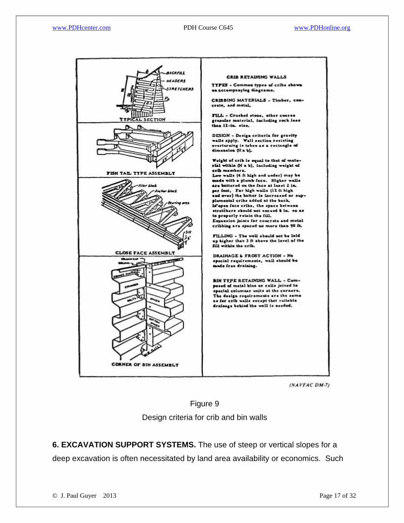
5. CRIB WALL. Design criteria of crib walls are presented in figure 9.
www.PDHcenter.com PDH Course C645 www.PDHonline.org
© J. Paul Guyer 2013 Page 17 of 32
Figure 9
Design criteria for crib and bin walls
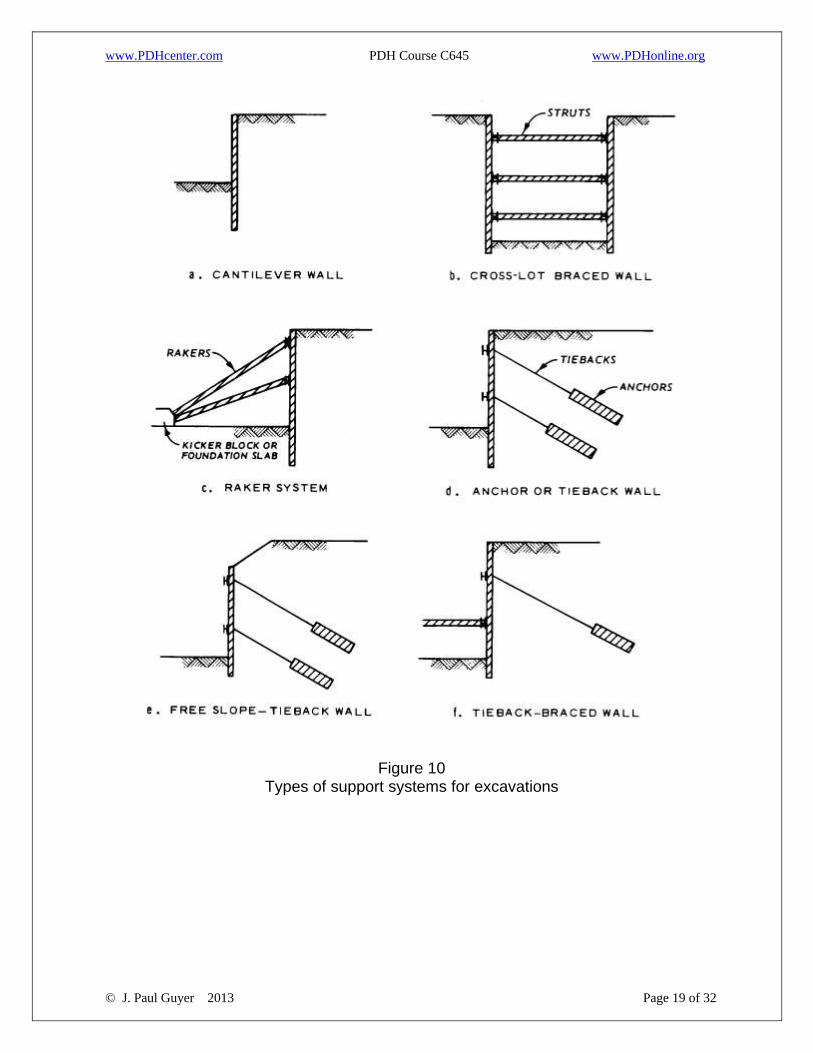
6. EXCAVATION SUPPORT SYSTEMS. The use of steep or vertical slopes for a
deep excavation is often necessitated by land area availability or economics. Such

www.PDHcenter.com PDH Course C645 www.PDHonline.org
© J. Paul Guyer 2013 Page 18 of 32
slopes are commonly supported by a cantilever wall (only for shallow excavations), a
braced wall, or a tieback wall (fig 10). In some cases, it may be economical to mix
systems, such as a free slope and a tieback wall or a tieback wall and a braced wall.
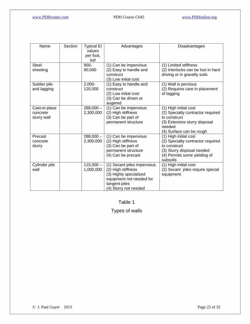
Table 1 summarizes the wall types with their typical properties and advantages and
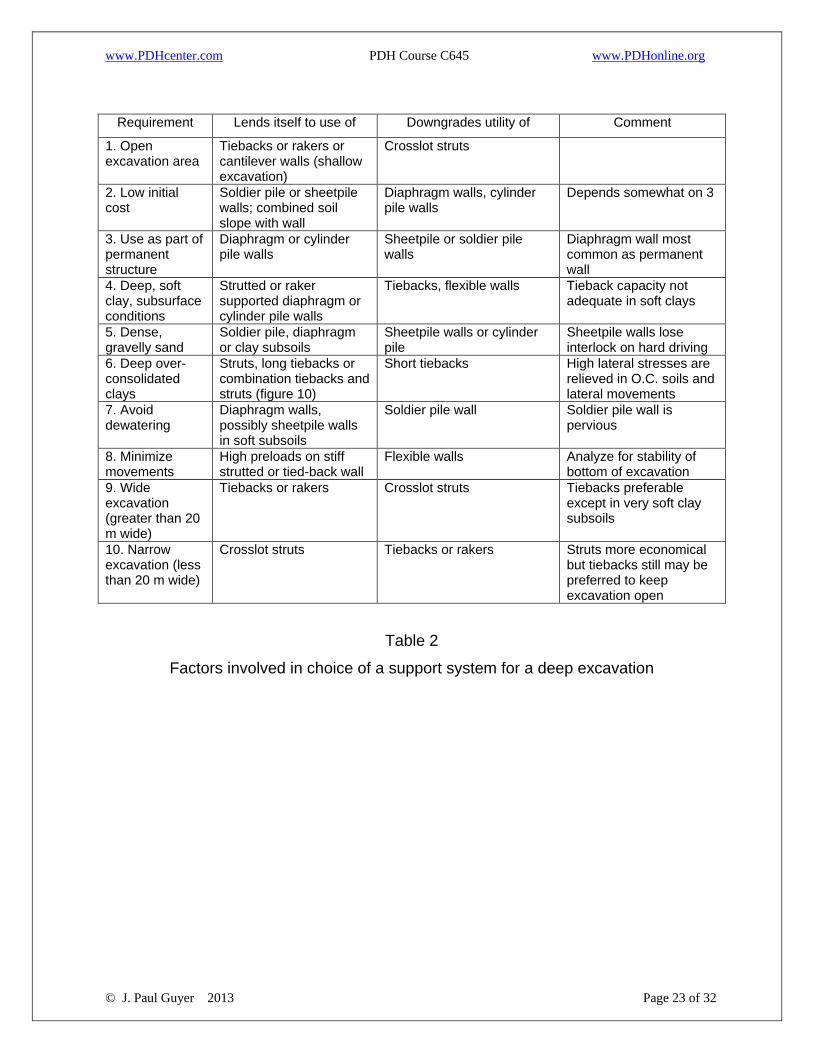
disadvantages. Table 2 lists factors for selecting wall support systems for a deep
excavation (>20 feet). Table 3 gives design parameters, such as factors of safety,
heave problems, and supplemental references.
www.PDHcenter.com PDH Course C645 www.PDHonline.org
© J. Paul Guyer 2013 Page 19 of 32
Figure 10 Types of support systems for excavations
www.PDHcenter.com PDH Course C645 www.PDHonline.org
© J. Paul Guyer 2013 Page 20 of 32
7. STRUTTED EXCAVATIONS.
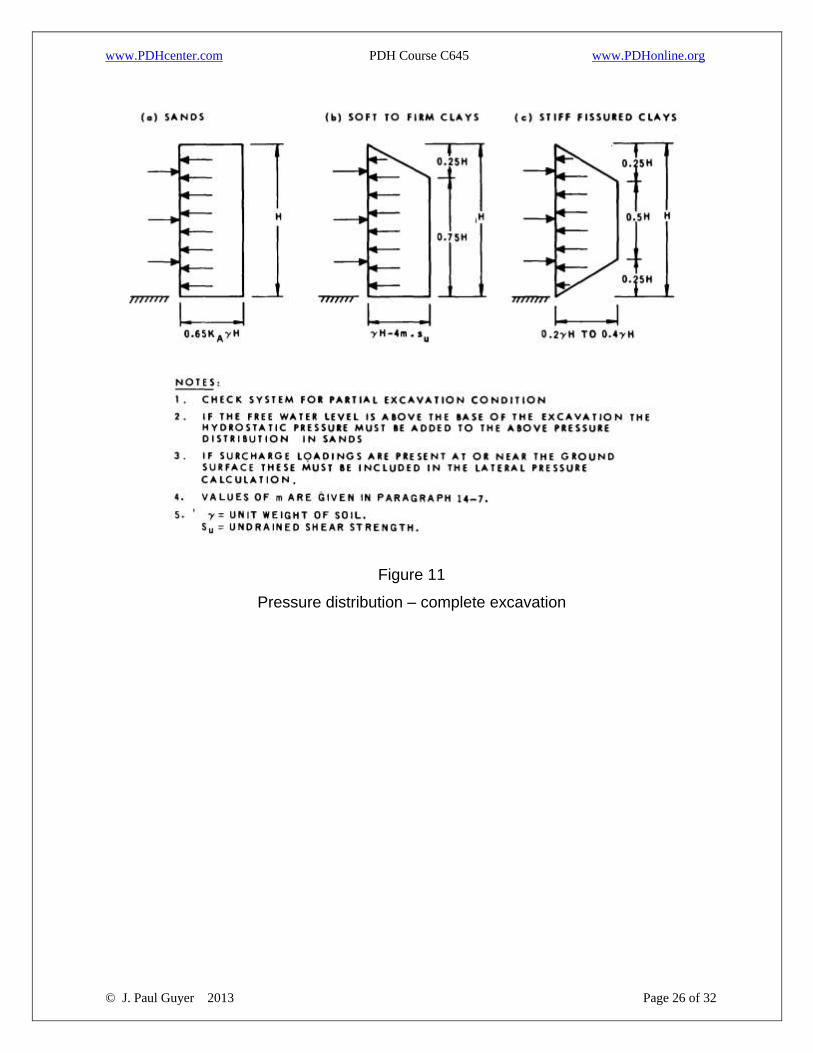
7.1 EMPIRICAL DESIGN EARTH PRESSURE DIAGRAMS developed from
observations are shown in figure 11. In soft to medium clays, a value of m = 1.0
should be applied if a stiff stratum is present at or near the base of the excavation. If
the soft material extends to a sufficient depth below the bottom of the excavation and
significant plastic yielding occurs, a value of 0.4 should be used for m. The degree of
plastic yielding beneath an excavation is governed by the stability number N
expressed as:
N = γH/su (eq 2)
where γ, H, and su, are defined in figure 11. If N exceeds about 4, m < 1.0.
7.2 FOR STIFF-FISSURED CLAYS, diagram (c) of figure 11 applies for any value of
N. If soft clays, diagram (b) applies except when the computed maximum pressure
falls below the value of the maximum pressure in diagram (c). In these cases,
generally for N < 5 or 6, diagram (c) is used as a lower limit. There are no design rules
for stiff intact clays and for soils characterized by both c and f such as sandy clays,
clayey sands, or
cohesive silts.
7.3 THE UPPER TIER OF BRACING should always be installed near the top of the
cut, although computations may indicate that it could be installed at a greater depth.
Its location should not exceed 2su below the top of the wall.
7.4 UNBALANCED WATER PRESSURES should be added to the earth pressures
where the water can move freely through the soil during the life of the excavation.
Buoyant unit weight is used for the soil below water. Where undrained behavior of a
soil is considered to apply, the use of total unit weights in calculating earth pressures
automatically accounts for the loads produced by groundwater (fig 11). Pressures due
www.PDHcenter.com PDH Course C645 www.PDHonline.org
© J. Paul Guyer 2013 Page 21 of 32
to the surcharge load are computed as indicated in previous discussions and added to
the earth and water pressures.
7.5 EACH STRUT is assumed to support an area extending halfway to the adjacent
strut (fig 11). The strut load is obtained by summing the pressure over the
corresponding tributary area. Temperature effects, such as temperature increase or
freezing of the retained material, may significantly increase strut loads.
7.6 SUPPORT is carried to the sheeting between the struts by horizontal structural
members (wales). The wale members should be designed to support a uniformly
distributed load equal to the maximum pressure determined from figure 11 times the
spacing between the wales. The wales may be assumed to be simply supported
(pinned) at the struts.
www.PDHcenter.com PDH Course C645 www.PDHonline.org
© J. Paul Guyer 2013 Page 22 of 32
Name Section Typical EI values
per foot, ksf
Advantages Disadvantages
Steel sheeting
900-90,000
(1) Can be impervious (2) Easy to handle and construct (3) Low initial cost
(1) Limited stiffness (2) Interlocks can be lost in hard driving or in gravelly soils
Soldier pile and lagging
2,000-120,000
(1) Easy to handle and construct (2) Low initial cost (3) Can be driven or augered
(1) Wall is pervious (2) Requires care in placement of lagging
Cast-in-place concrete slurry wall
288,000 – 2,300,000
(1) Can be impervious (2) High stiffness (3) Can be part of permanent structure
(1) High initial cost (2) Specialty contractor required to construct (3) Extensive slurry disposal needed (4) Surface can be rough
Precast concrete slurry
288,000 – 2,300,000
(1) Can be impervious (2) High stiffness (3) Can be part of permanent structure (4) Can be precast
(1) High initial cost (2) Specialty contractor required to construct (3) Slurry disposal needed (4) Permits some yielding of subsoils
Cylinder pile wall
115,000 – 1,000,000
(1) Secant piles impervious (2) High stiffness (3) Highly specialized equipment not needed for tangent piles (4) Slurry not needed
(1) High initial cost (2) Secant piles require special equipment
Table 1
Types of walls
www.PDHcenter.com PDH Course C645 www.PDHonline.org
© J. Paul Guyer 2013 Page 23 of 32
Requirement Lends itself to use of Downgrades utility of Comment
1. Open excavation area
Tiebacks or rakers or cantilever walls (shallow excavation)
Crosslot struts
2. Low initial cost
Soldier pile or sheetpile walls; combined soil slope with wall
Diaphragm walls, cylinder pile walls
Depends somewhat on 3
3. Use as part of permanent structure
Diaphragm or cylinder pile walls
Sheetpile or soldier pile walls
Diaphragm wall most common as permanent wall
4. Deep, soft clay, subsurface conditions
Strutted or raker supported diaphragm or cylinder pile walls
Tiebacks, flexible walls Tieback capacity not adequate in soft clays
5. Dense, gravelly sand
Soldier pile, diaphragm or clay subsoils
Sheetpile walls or cylinder pile
Sheetpile walls lose interlock on hard driving
6. Deep over-consolidated clays
Struts, long tiebacks or combination tiebacks and struts (figure 10)
Short tiebacks High lateral stresses are relieved in O.C. soils and lateral movements
7. Avoid dewatering
Diaphragm walls, possibly sheetpile walls in soft subsoils
Soldier pile wall Soldier pile wall is pervious
8. Minimize movements
High preloads on stiff strutted or tied-back wall
Flexible walls Analyze for stability of bottom of excavation
9. Wide excavation (greater than 20 m wide)
Tiebacks or rakers Crosslot struts Tiebacks preferable except in very soft clay subsoils
10. Narrow excavation (less than 20 m wide)
Crosslot struts Tiebacks or rakers Struts more economical but tiebacks still may be preferred to keep excavation open
Table 2
Factors involved in choice of a support system for a deep excavation
www.PDHcenter.com PDH Course C645 www.PDHonline.org
© J. Paul Guyer 2013 Page 24 of 32
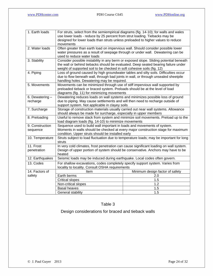
1. Earth loads For struts, select from the semiempirical diagrams (fig. 14-10); for walls and wales
use lower loads - reduce by 25 percent from strut loading. Tiebacks may be designed for lower loads than struts unless preloaded to higher values to reduce movements
2. Water loads Often greater than earth load on impervious wall. Should consider possible lower water pressures as a result of seepage through or under wall. Dewatering can be used to reduce water loads
3. Stability Consider possible instability in any berm or exposed slope. Sliding potential beneath the wall or behind tiebacks should be evaluated. Deep seated bearing failure under weight of supported soil to be checked in soft cohesive soils (fig. 12)
4. Piping Loss of ground caused by high groundwater tables and silty soils. Difficulties occur due to flow beneath wall, through bad joints in wall, or through unsealed sheetpile handling holes. Dewatering may be required.
5. Movements Movements can be minimized through use of stiff impervious wall supported by preloaded tieback or braced system. Preloads should be at the level of load diagrams (fig. 11) for minimizing movements
6. Dewatering – recharge
Dewatering reduces loads on wall systems and minimizes possible loss of ground due to piping. May cause settlements and will then need to recharge outside of support system. Not applicable in clayey soils
7. Surcharge Storage of construction materials usually carried out near wall systems. Allowance should always be made for surcharge, especially in upper members
8. Preloading Useful to remove slack from system and minimize soil movements. Preload up to the load diagram loads (fig. 14-10) to minimize movements
9. Construction sequence
Sequence used to build wall important in loads and movements of system. Moments in walls should be checked at every major construction stage for maximum condition. Upper struts should be installed early
10. Temperature Struts subject to load fluctuation due to temperature loads; may be important for long struts
11. Frost penetration
In very cold climates, frost penetration can cause significant loading on wall system. Design of upper portion of system should be conservative. Anchors may have to be heated
12. Earthquakes Seismic loads may be induced during earthquake. Local codes often govern.
13. Codes For shallow excavations, codes completely specify support system. Varies from locality to locality. Consult OSHA requirements
14. Factors of safety
Item Minimum design factor of safety
Earth berms 2.0
Critical slopes 1.5
Non-critical slopes 1.2
Basal heaves 1.5
General stability 1.5
Table 3
Design considerations for braced and tieback walls
www.PDHcenter.com PDH Course C645 www.PDHonline.org
© J. Paul Guyer 2013 Page 25 of 32
8. STABILITY OF BOTTOM OF EXCAVATION.
8.1 PIPING IN SAND. The base of an excavation in sand is usually stable unless an
unbalanced hydrostatic head creates a "quick" condition. Among the methods to
eliminate instability are dewatering, application of a surcharge load at the bottom of the
excavation, and deeper penetration of the piling.
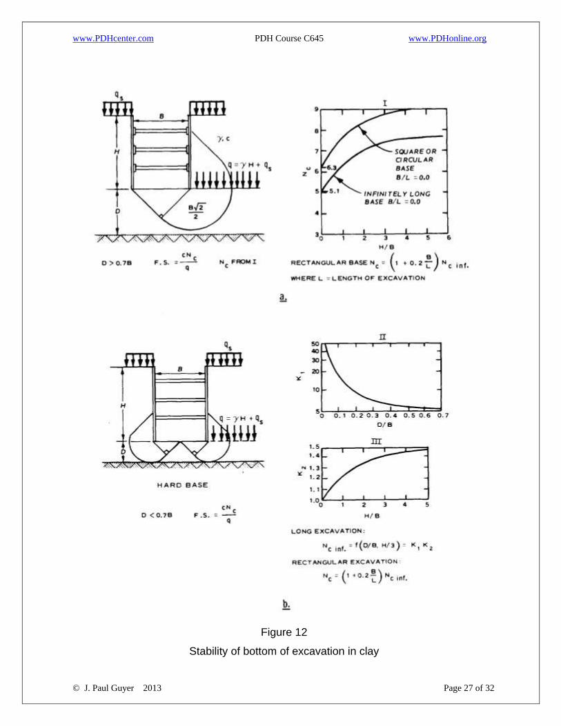
8.2 HEAVING IN CLAYS. The stability against heave of the bottom of an excavation in
soft clay may be evaluated from figure 12. If the factor of safety is less than 1.5, the
piling should be extended below the base of the excavation. Heave may also occur
because of unrelieved hydrostatic pressures in a permeable layer located below the
clay.
8.3 CARE OF SEEPAGE. Small amounts of seepage into the excavation can be
controlled by pumping from sumps. Such seepage can be expected if the excavation
extends below the water table into permeable soils. If the soils consist of fine sands
and silts, the sumps should be routinely monitored for evidence of fines being washed
from the soil by seepage. If large quantities of fine-grained materials are found in the
sumps, precautionary steps should be taken to make the lagging or sheeting
watertight to avoid excessive settlements adjacent to the excavation.
www.PDHcenter.com PDH Course C645 www.PDHonline.org
© J. Paul Guyer 2013 Page 26 of 32
Figure 11
Pressure distribution – complete excavation
www.PDHcenter.com PDH Course C645 www.PDHonline.org
© J. Paul Guyer 2013 Page 27 of 32
Figure 12
Stability of bottom of excavation in clay

www.PDHcenter.com PDH Course C645 www.PDHonline.org
© J. Paul Guyer 2013 Page 28 of 32
www.PDHcenter.com PDH Course C645 www.PDHonline.org
© J. Paul Guyer 2013 Page 29 of 32
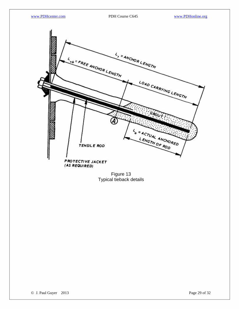
Figure 13
Typical tieback details
www.PDHcenter.com PDH Course C645 www.PDHonline.org
© J. Paul Guyer 2013 Page 30 of 32
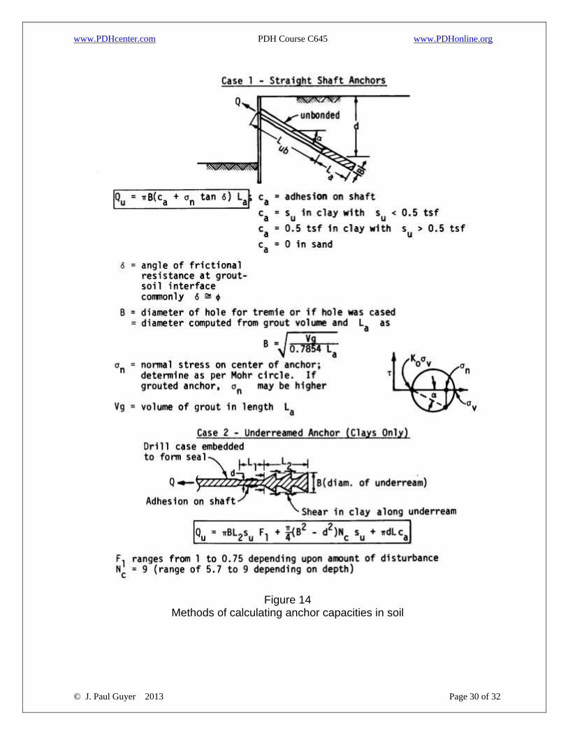
Figure 14 Methods of calculating anchor capacities in soil
www.PDHcenter.com PDH Course C645 www.PDHonline.org
© J. Paul Guyer 2013 Page 31 of 32
9. ANCHORED WALLS.
9.1 TIEBACKS have supplanted both strut and raker systems in many instances to
support wide excavations. The tieback (fig 13) connects the wall to an anchorage
located in a zone where significant soil movements do not occur. The anchorage may
be in soil or rock; soft clays probably present the only condition where an anchorage in
soil cannot be obtained reliably. In figure 13, the distance Lub should extend beyond
the "Rankine" zone some distance. This distance is necessary, in part, to obtain
sufficient elongation in anchored length of rod La during jacking so that soil creep
leaves sufficient elongation that the design load is retained in the tendon. After jacking,
if the soil is corrosive and the excavation is open for a long time, the zone Lub may be
grouted. Alternatively, the length of tendon Lub is painted or wrapped with a grease
impregnated wrapper (prior to placing in position).
9.2 THE TIEBACK TENDON may be either a single high-strength bar or several high-
strength cables (fy on the order of 200 to 270 kips per square inch) bunched. It is
usually inclined so as to reach better bearing material, to avoid hole collapse during
drilling, and to pass under utilities. Since only the horizontal component of the tendon
force holds the wall, the tendon should be inclined a minimum.
9.3 TIEBACK ANCHORAGES may be drilled using continuous flight earth augers
(commonly 4 to 7 inches in diameter) and may require casing to hold the hole until
grout is placed in the zone La of figure 13, at which time the casing is withdrawn. Grout
is commonly used under a pressure ranging from 5 to 150 pounds per square inch.
Under-reaming may be used to increase the anchor capacity in cohesive soil. Belling
is not possible in cohesionless soils because of hole caving. Typical formulas that can
be used to compute the capacity of tieback anchorages are given in figure 14.
9.4 EXACT KNOWLEDGE OF THE ANCHOR CAPACITY IS NOT NEEDED as all the
anchors are effectively "proof-tested" (about 120 to 150 percent of design load) when
www.PDHcenter.com PDH Course C645 www.PDHonline.org
© J. Paul Guyer 2013 Page 32 of 32
the tendons are tensioned for the design load. One or more anchors may be loaded to
failure; however, as the cost of replacing a failed anchor is often two to three times the
cost of an initial insertion, care should be taken not to fail a large number of anchors in
any-test program. If the tieback extends into the property of others, permission, and
possibly a fee, will be required. The tieback tendons and anchorages should normally
be left in situ after construction is completed. See table 3 for additional design
considerations.