Embed Size (px)
Citation preview

An Approved Continuing Education Provider
PDHonline Course C781 (4 PDH)
An Introduction to Petroleum Fuel
Facilities: Atmospheric Storage Tanks
J. Paul Guyer, P.E., R.A.
2015
PDH Online | PDH Center
5272 Meadow Estates Drive
Fairfax, VA 22030-6658
Phone & Fax: 703-988-0088
www.PDHonline.org
www.PDHcenter.com

www.PDHcenter.com PDHonline Course C781 www.PDHonline.org
©2014 J. Paul Guyer Page 2 of 54
An Introduction to Petroleum Fuel Facilities: Atmospheric
Storage Tanks
J. Paul Guyer, P.E., R.A.
CONTENTS
1. INTRODUCTION
2. GENERAL REQUIREMENTS
3. GENERAL CRITERIA
4. HORIZONTAL ABOVEGROUND TANKS (SINGLE-WALL STEEL)
5. HORIZONTAL ABOVEGROUND TANKS (DOUBLE-WALL STEEL)
6. HORIZONTAL ABOVEGROUND TANKS (FIRE-RESISTANT)
7. HORIZONTAL ABOVEGROUND TANKS (PROTECTED TANKS)
8. ABOVEGROUND VERTICAL STORAGE TANKS
9. UNDERGROUND HORIZONTAL STORAGE TANKS
10. UNDERGROUND VERTICAL STORAGE TANKS (CUT AND COVER)
11. APPURTENANCES
12. HEATERS
13. UNDERGROUND STORAGE TANK SPILL CONTAINMENT SYSTEMS
14. ABOVEGROUND TANK SPILL CONTAINMENT SYSTEMS
15. MISCELLANEOUS USE TANKS
16. SHIPBOARD OFF-LOAD FUEL STORAGE TANKS
(This publication is adapted from the Unified Facilities Criteria of the United States government which are in the public domain, have been authorized for unlimited distribution, and are not copyrighted.) (Figures, tables and formulas in this publication may at times be a little difficult to read, but they are the best available. DO NOT PURCHASE THIS PUBLICATION IF THIS LIMITATION IS UNACCEPTABLE TO YOU.)

www.PDHcenter.com PDHonline Course C781 www.PDHonline.org
©2014 J. Paul Guyer Page 3 of 54
1. INTRODUCTION. This discussion provides guidance for the design of bulk storage
tanks, operating storage tanks, ground vehicle fueling tanks, miscellaneous use tanks,
product recovery system tanks, contaminated fuel storage tanks, and jet engine test
cell fuel storage tanks. Design guidance on issues related to storage tanks such as
protection, location, coatings, product recovery, and spill containment systems are
also covered in this chapter. This chapter generally applies to new tanks.
2. GENERAL REQUIREMENTS. Do not start design of any fueling system without first
becoming completely familiar with General Design Requirements.
3. GENERAL CRITERIA. Design liquid fuel storage tanks to comply with the
operational requirements of the particular command having jurisdiction of the facility.
Ensure that the design is appropriate for the mission of the facility. Consider the
operational requirements of the users of the fuel.
3.1 MATERIALS. All aboveground storage tanks shall be constructed of steel or
concrete encased steel.
3.2 PROTECTION. Provide protection to preserve product quality and ensure minimal
losses by evaporation, dilution, leakage, substitution, theft, contamination, attack,
sabotage, fire, and damage to the environment. Use aboveground steel tanks unless
the mission of the facility or other practical considerations dictate that underground
tanks be used. Cut and cover (buried vertical) tanks are not normally used in the
continental United States. Cut and cover tanks may be required if the dispensing
system is located in clear zones or explosive cordon areas. Conduct economic,
operational, and mechanical analyses of remotely locating the pump house/system
from the hydrant system versus constructing cut and cover tanks. For tanks located in
areas subject to flooding, design in accordance with NFPA 30.
3.3 DESIGN REQUIREMENTS. Fuel storage facilities provide an operating and
reserve supply of fuel. The types and sizes of storage tanks depend on safety,

www.PDHcenter.com PDHonline Course C781 www.PDHonline.org
©2014 J. Paul Guyer Page 4 of 54
economics, terrorist activity, locality, and intended service. Provide separate storage
for each type and grade of fuel. For aviation activities, provide a minimum of two tanks
for each type of fuel.
3.4 STORAGE CAPACITY. The capacity or size of each fuel storage tank is based
upon the logistical and mission requirements for the facility and any other facility to be
supported from it. For a stated volume of each fuel, fewer tanks of larger size will
result in maximum economy. The appropriate Owner approval will determine the
number and size of tanks required. Provide a minimum of two tanks at aviation
activities for each type of aviation turbine fuel to receive and isolate new receipts until
tested and checked for quality and quantity while the facility continues to function with
stocks on hand. In general, capacities of individual tanks should not exceed 50 percent
of the total storage volume required for each type and grade of fuel. Do not provide
tanks with capacities greater than 100,000 barrels (16,000,000 L) except when larger
tanks are specifically authorized by the Owner.
3.5 TANK SPACING.
3.5.1 VERTICAL TANKS. Provide a minimum distance between the shells of vertical
tanks, both aboveground and underground, of not less than one diameter of the larger
tank.
3.5.2 HORIZONTAL UNDERGROUND TANKS. Provide a minimum clearance
between shells of adjacent horizontal underground tanks of 3 feet (0.9 m).
3.5.3 HORIZONTAL ABOVEGROUND TANKS (SINGLE-WALL AND DOUBLE-
WALL STEEL) (NON-FIRE RESISTANT AND NON-PROTECTED). Provide a
minimum clearance between aboveground horizontal tanks with capacities 50,000
gallons (189,300 L) or under as follows:
www.PDHcenter.com PDHonline Course C781 www.PDHonline.org
©2014 J. Paul Guyer Page 5 of 54
a) Arrange tanks in pairs with a minimum of 5 feet (1.5 m) between tanks in each pair
and 10 feet (3 m) between adjacent tanks of two pairs in the same row.
b) Space adjacent groups of more than two pairs in a single row with at least 20 feet (6
m) between the nearest tanks of the groups.
c) Provide a minimum end-to-end spacing between tanks in longitudinal rows of 20
feet (6 m).
d) Provide a UL nameplate on tanks stating that the tanks are approved for that
material and service.
e) In addition to requirements listed in this paragraph, tanks located in facilities
governed by NFPA 30A, such as marine/motor fuel dispensing facilities, shall comply
with NFPA 30A.
3.5.4 HORIZONTAL ABOVEGROUND TANKS (FIRE RESISTANT). Provide
minimum clearance and spacing between fire resistant, secondarily contained
aboveground horizontal tanks in compliance with NFPA 30 and NFPA 30A as
applicable.
3.5.5 HORIZONTAL ABOVEGROUND TANKS (PROTECTED). Provide minimum
clearance and spacing between protected, secondarily contained aboveground
horizontal tanks in compliance with NFPA 30 and NFPA 30A as applicable.
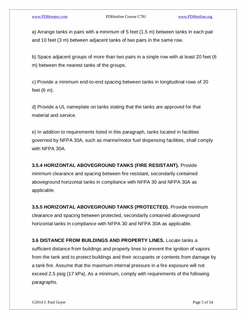
3.6 DISTANCE FROM BUILDINGS AND PROPERTY LINES. Locate tanks a
sufficient distance from buildings and property lines to prevent the ignition of vapors
from the tank and to protect buildings and their occupants or contents from damage by
a tank fire. Assume that the maximum internal pressure in a fire exposure will not
exceed 2.5 psig (17 kPa). As a minimum, comply with requirements of the following
paragraphs.

www.PDHcenter.com PDHonline Course C781 www.PDHonline.org
©2014 J. Paul Guyer Page 6 of 54
3.6.1 UNDERGROUND TANKS. Locate underground tanks with respect to buildings
or similar structures so that the soil pressure created by the building foundations will
not be transmitted to the tank. Pumping facilities which are often located directly above
underground tanks are accepted. Locate horizontal cylindrical tanks less than or equal
to 12 feet (3.7 m) in diameter not less than 10 feet (3 m) from the nearest point of an
adjacent building or property line. Locate vertical underground tanks at least 25 feet
(7.6 m) from the nearest point of an adjacent building and 50 feet (15 m) from the
nearest property line.
3.6.2 ABOVEGROUND TANKS. Locate aboveground tanks with consideration of fire
safety. The first consideration is to prevent the ignition of vapors from the tank, and the
second consideration is to protect the building and its occupants or contents from
damage by a tank fire. As a protective measure, provide all aboveground tanks with
some form of emergency relief venting for fire exposure in accordance with NFPA 30.
In the following, it is assumed that all tanks are constructed or equipped so that the
maximum internal pressure in a fire exposure will not exceed 2.5 psi (17 kPa).
Required minimum distances for aboveground tanks from buildings and property lines
are as follows:
a) Tanks, all sizes and types, not protected or fire-resistant, containing petroleum fuels
with a flash point less than 100 degrees F (38 degrees C), 100 feet (30 m) or one tank
diameter, whichever is greater, \1\ with the exception that tanks /1/ located in facilities
governed by NFPA 30A, such as marine/motor fuel dispensing facilities, shall comply
with NFPA 30A \1\ criteria /1/.
b) Tanks, not protected or fire-resistant, containing petroleum fuels with a flash point of
100 degrees F (38 degrees C) or greater in accordance with the following:
www.PDHcenter.com PDHonline Course C781 www.PDHonline.org
©2014 J. Paul Guyer Page 7 of 54
c) For aboveground, fire-resistant tanks in facilities governed by NFPA 30A, use NFPA
30A guidelines.
d) For aboveground, protected tanks, use NFPA 30 guidelines. Protected tanks
located in facilities governed by NFPA 30A, such as marine/motor fuel dispensing
facilities, shall comply with NFPA 30A \1\ criteria /1/.
3.7 DISTANCE FROM ROADWAY, RAILROADS AND POWER LINES. For tanks
located in facilities governed by NFPA 30A, use NFPA 30A guidelines.. For all other
storage tanks, the minimum distances from adjacent roadways, railways, railroads,
and overhead electric power lines are as follows:
3.7.1 UNDERGROUND TANKS. Spacing and clearances for underground tanks shall
be:
a) A minimum of 25 feet (7.6 m) from regularly traveled roads and highways, not
including tank farm utility and fire access roads.
b) 25 feet (7.6 m) from railroad spur tracks not used for through traffic.
c) No less than 100 feet (30 m) from main railroad tracks carrying through traffic.
d) 50 feet (15 m) from overhead electric power transmission and distribution wires.
3.7.2 ABOVEGROUND TANKS.

www.PDHcenter.com PDHonline Course C781 www.PDHonline.org
©2014 J. Paul Guyer Page 8 of 54
a) The greater of 100 feet (30 m) or one tank diameter from regularly traveled roads
and highways, not including tank farm utility and fire access roads.
b) 50 feet (15 m) from railroad spur tracks not used for through traffic.
c) 200 feet (60 m) from main railroad tracks carrying through traffic.
d) 50 feet (15 m) from overhead electric power transmission and distribution wires.
3.8 DISTANCE FROM TANK TRUCK AND TANK CAR OFF-LOADING AND
LOADING FACILITIES. For tanks located in facilities governed by NFPA 30A, use
NFPA 30A guidelines. For fire resistant or protected horizontal aboveground tanks and
underground tanks, provide a minimum separation of 25 feet (7.6 m) from tank truck
and tank car off-loading and loading facilities. For all other tanks, provide a minimum
separation of 50 feet (15 m) from tank truck and tank car off-loading and loading
facilities.
3.9 INTERIOR COATINGS. To extend the life of steel storage tanks, coat new tanks
according to the following guidelines:
a) Vertical tanks
All aviation, diesel fuel marine (F-76), additive, and lube oil tank. Interiors shall
be 100 percent coated, including floor, shell, and underside of the roof.
Other products. Coat the floor, the underside of the fixed roof, and the bottom
40 inches (1000 mm) of the tank shell. Additional coating of up to 100 percent
requires economic justification and The Owner approval. \1\ Tanks containing
E85 are not to be coated internally unless otherwise approved by The Owner.
b) Horizontal tanks
For all products, tank interiors shall be 100 percent coated. Tanks containing
E85 are not to be coated internally unless otherwise approved by The Owner.

www.PDHcenter.com PDHonline Course C781 www.PDHonline.org
©2014 J. Paul Guyer Page 9 of 54
c) For all products coat the interior and exterior of carbon steel piping located inside
the tank, and steel appurtenances inside all tanks. Carbon steel piping, and steel
appurtenances located inside of tanks containing E85 are not to be coated internally
unless otherwise approved by The Owner.
3.10 EXTERIOR COATINGS.
a) Protect the exterior surface of all aboveground steel tanks by coating in accordance
with appropriate guide specifications.
b) Protect the exterior surfaces of all underground horizontal steel tanks with a factory-
applied coating specified in the appropriate guide specifications.
c) For protected tanks, with exterior steel containment, consider exterior fiberglass
cladding for extremely corrosive atmospheres or seaside locations.
3.11 FILL PIPING. Size the pipe so that the velocity does not exceed 12 feet (3.7 m)
per second at maximum flow rate. Provide a means for reducing the velocity of flow to
3 feet (0.9 m) per second until the filling inlet nozzle is completely submerged and/or
the floating pan has lifted off its legs.
3.12 VAPOR EMISSION CONTROL SYSTEMS. Provide a vapor emission control
system for tanks that store products having a true vapor pressure of 0.75 psia (5 kPa)
or more located in air pollution control areas in which the discharge of petroleum
vapors is controlled or prohibited. Ensure that the system has sufficient capacity to
control the vapor discharged from the tank vents at maximum filling rate in
conformance with local air quality regulations. If gasoline is being handled, provide, as
a minimum, Stage I vapor recovery and the piping for Stage II. If not required by local
or state regulations at time of construction, connect the Stage II piping to the tank and
cap it at the dispenser.
3.13 STRAPPING TABLES.

www.PDHcenter.com PDHonline Course C781 www.PDHonline.org
©2014 J. Paul Guyer Page 10 of 54
Provide two API MPMS Chapter 2 strapping tables for all tanks greater than 5,000
gallons (19,000 L). Provide one of the tables in U.S. Customary units reading in 1/16-
inch increments, gallons and barrels and one in metric units reading in 2mm
increments, liters and cubic meters. Provide electronic media data files. Determine
strapping table volumes for tanks of 5,000gallons (19,000 L) and larger using physical
measurements, not calculated values. The tables are to be calibrated for critical
measurement and certified by a Professional Engineer. For tanks less than 5,000
gallons (19,000 L), provide strapping table certified by the tank manufacturer that
reads 1/16-inch (2mm) increments in gallons (liters).
3.14 PRODUCT RECOVERY SYSTEMS
3.14.1 GENERAL DESIGN CONSIDERATIONS. Provide pumps, piping, valves, and
tanks to collect and store usable aviation turbine fuel which would otherwise become
waste from operational or maintenance activities. Consider a product recovery system
for other products. Include a tank to collect fuel/water mixtures from tank and
equipment sumps, equipment drains, product saver tanks, high point vents, low point
drains, and any other equipment from which fuel/water mixtures can be collected.
Separate the fuel and water portions. Filter the fuel portion and return to operating
storage tanks. Do not discharge the water portion to surface water without additional
treatment and permits or treat the water portion as wastewater. Refer to DoD Standard
Design AW 78-24-28. These systems are standard with the hydrant and aircraft direct
fueling systems.
3.14.2 PRODUCT RECOVERY TANKS. For hydrant and aircraft direct fueling
systems provide the tank directed by the Owner. For other systems, provide a tank
with, at a minimum, the following appurtenances:
a) Level gauge.
b) Overfill protection level control valve.
c) High and low level switches with alarms and controls.

www.PDHcenter.com PDHonline Course C781 www.PDHonline.org
©2014 J. Paul Guyer Page 11 of 54
d) A motor driven fuel transfer pump that returns recovered fuel back to the system
through a hard piped connection.
e) A motor driven sump pump for emptying the tank.
f) Manual gauging hatch.
g) Vent.
h) ATG system for aboveground product recovery tanks having a capacity more than
or equal to 4,000 gallons (15,000 L).
i) Do not allow sight flow indicators to be installed on product recovery tanks.
3.14.3 VERTICAL STORAGE TANKS. In addition to the product recovery tank(s) for
the facility, all vertical storage tanks storing aviation turbine fuel should include a
product saver tank with electric pump, unless the tank is equipped with a
filter/separator to remove water from the sump. A product saver tank is a small
aboveground tank piped and valved to allow drawing water from the bottom of the
storage tank and returning the product after the water has been separated and
disposed of in accordance with environmental regulations.
3.15 REGISTRATION. Register all tanks with the appropriate state and local agencies
as required. All tanks shall have a nameplate installed in accordance with API Std 650.

www.PDHcenter.com PDHonline Course C781 www.PDHonline.org
©2014 J. Paul Guyer Page 12 of 54
4. HORIZONTAL ABOVEGROUND TANKS (SINGLE-WALL STEEL)
4.1 GENERAL DESIGN CONSIDERATIONS. If small factory-built aboveground
storage tanks are required, use horizontal tanks. Limit tank diameter to 12 feet (3.7 m)
or less and capacity to 50,000 gallon (191,000 L) or less. Require tank to be of
welded steel construction in accordance with UL 142. Plastic and/or fiberglass
aboveground storage tanks are not allowed. Requirements for all horizontal
aboveground storage tanks shall comply with NFPA 30 Chapter 22 Aboveground
Storage Tanks. Tanks located in facilities governed by NFPA 30A, such as
marine/motor fuel dispensing facilities, shall comply with NFPA 30A.
4.2 TANK DESIGN REQUIREMENTS.
a) Install the tank so that the bottom slopes downward toward one end at a slope of 1
percent. Locate transfer pumps or suction piping at the high end of the tank; locate
water drawoff at low end of the tank.
b) Provide water drawoff lines in each tank. For aviation fueling systems, arrange
piping so that the fuel in the tanks may be recirculated through the filter/separators.
c) Provide steel tanks with steel saddles or skids in accordance with UL 142. The
bottom of tank is to be no more than 12 inches (300 mm) above grade to avoid the
need for fireproofing. Mount steel supports on a reinforced concrete foundation.
d) Tanks shall be inspected in accordance with STI SP001 by a STI certified inspector
prior to commissioning.

www.PDHcenter.com PDHonline Course C781 www.PDHonline.org
©2014 J. Paul Guyer Page 13 of 54
5. HORIZONTAL ABOVEGROUND TANKS (DOUBLE-WALL STEEL)
5.1 GENERAL DESIGN CONSIDERATIONS. Limit tank diameter to 12 feet (3.7 m) or
less and capacity to 50,000 gallon (191,000 L) or less. Require tank to be of welded
steel construction in accordance with UL 142. No fiberglass aboveground storage
tanks are allowed. The main advantage of double-wall steel storage tanks over single-
wall steel storage tanks is that separate spill containment may not be required.
Secondary containment-type tanks can be used to provide spill control per NFPA 30, if
the capacity of the tank is no more than 12,000 gallons (45,400 L). The tank size may
be increased to 20,000 gallons (75,700 L) if Class II or III liquids are used. All of the
criteria in the NFPA regulations for the appropriate application must be met before a
secondary containment-type tank is used without separate spill containment.
Requirements for double-wall steel horizontal aboveground storage tanks shall comply
with NFPA 30, the chapter entitled, “Aboveground Storage Tanks”. Tanks located in
facilities governed by NFPA 30A, such as marine/motor fuel dispensing facilities, shall
comply with NFPA 30A.
5.2 TANK DESIGN REQUIREMENTS.
a) For flammable liquid installations, require additional curbing containment based on
tank filling rates if there is a chance of a fuel spill entering a critical area.
b) Install the tank so that the bottom slopes downward toward one end at a slope of 1
percent. Locate transfer pumps or suction piping at the high end of the tank; locate
water drawoff at low end of the tank.
c) Provide water drawoff lines in each tank. For aviation fueling systems, arrange
piping so that the fuel in the tanks may be recirculated through the filter/separators.

www.PDHcenter.com PDHonline Course C781 www.PDHonline.org
©2014 J. Paul Guyer Page 14 of 54
d) Provide protective bollards for tanks not surrounded by a dike. Bollards shall not be
less than 4 feet (1.2 m) high and 4-inches (100 mm) in diameter, of steel construction,
filled with concrete, and spaced not less than 4 feet (1.2 m) on center.
e) Provide steel tanks with steel saddles or skids in accordance with UL 142. The
bottom of tank is to be no more than 12 inches (300 mm) above grade to avoid the
need for fireproofing. Mount steel supports on a reinforced concrete foundation. Mount
rectangular (flat bottomed) tanks of 4,000 gallons (15,100 L) or greater 12 inches (300
mm) above grade to allow inspection and maintenance of the tank bottom.
f) Require the tank to be pressure-tested after installation.
g) Tanks shall be inspected in accordance with STI SP001 by a STI certified inspector
prior to commissioning.
h) A primary tank constructed of stainless steel is permitted when required.
i) Require support channels with anchor holes for earthquake/hurricane/flood restraint
tie down.
j) Require steel to be a minimum thickness of 3/16-inch (5 mm) for interior carbon steel
tank.

www.PDHcenter.com PDHonline Course C781 www.PDHonline.org
©2014 J. Paul Guyer Page 15 of 54
6. HORIZONTAL ABOVEGROUND TANKS (FIRE-RESISTANT)
6.1 GENERAL DESIGN CONSIDERATIONS. When small (250 to 20,000 gallon (900
to 75,000 L) capacity) aboveground storage tanks are required and there are
clearance or fire exposure problems and the additional cost can be justified, consider
the use of fire-resistant storage tanks. The main advantage of fire-resistant tanks over
the single wall steel tanks is that separate spill containment may not be required and
the vault system provides an added measure of fire protection. Secondary
containment-type tanks can be used to provide spill control per NFPA 30, if the
capacity of the tank is no more than 12,000 gallons (45,400 L). The tank size may be
increased to 20,000 gallons (75,700 L) if Class II or III liquids are used. All of the
criteria in the NFPA regulations for the appropriate application must be met before a
secondary containment-type tank is used without separate spill containment. Require
tanks to be factory-constructed with a UL 142 welded steel primary tank. Tanks may
be used in applications where, in addition to the above considerations, construction of
a separate spill containment system for secondary containment purposes would have
a negative impact on operations and/or aesthetics. Tanks located close to buildings or
with integral fuel dispensers must be UL-listed secondary containment tanks, utilizing
steel inner and outer tanks that can provide interstitial containment which is both
pressure testable and verifiable. Such tanks usually have a fill of regular or insulating
concrete. Ensure the two-hour fire rating meets or exceeds all requirements of NFPA
30A for “fire resistance” tanks, and provides a minimum two-hour fire rating in
accordance with 2080.
6.2 TANK DESIGN REQUIREMENTS.
a) For flammable liquid installations, require additional curbing containment based on
tank filling rates if there is a chance of a fuel spill entering a critical area.

www.PDHcenter.com PDHonline Course C781 www.PDHonline.org
©2014 J. Paul Guyer Page 16 of 54
b) Install the tank so that the bottom slopes downward toward one end at a slope of 1
percent. Locate transfer pumps or suction piping at the high end of the tank; locate
water drawoff at low end of the tank.
c) Provide water drawoff lines in each tank. For aviation fueling systems, arrange
piping so that the fuel in the tanks may be recirculated through the filter/separators.
d) A primary tank constructed of stainless steel is permitted when required.
e) Require support channels with anchor holes for earthquake/hurricane/flood restraint
tie down.
f) Require steel to be a minimum thickness of 3/16-inch (5 mm) for the interior carbon
steel tank.
g) Mount rectangular (flat bottomed) tanks of 4,000 gallons (15,100 L) or greater 12
inches (300 mm) above grade to allow inspection and maintenance of the tank bottom.
h) Provide protective bollards in traffic areas. Bollards shall be not less than 4 feet (1.2
m) high and 4-inches (100 mm) in diameter, of steel construction, filled with concrete
and spaced not less than 4 feet (1.2 m) on center.
i) Require the tank to be pressure-tested after installation.
j) Tanks shall be inspected in accordance with STI SP001 by a STI certified inspector
prior to commissioning.

www.PDHcenter.com PDHonline Course C781 www.PDHonline.org
©2014 J. Paul Guyer Page 17 of 54
7. HORIZONTAL ABOVEGROUND TANKS (PROTECTED TANKS)
7.1 GENERAL DESIGN CONSIDERATIONS. When small (250 to 20,000 gallon (900
to 75,000 L) capacity) aboveground storage tanks are required and there are
clearance or fire exposure problems and the additional cost can be justified, consider
the use of protected storage tanks. The main advantages of protected tanks over the
single wall steel tanks are that a separate dike (containment) may not be required and
the vault system provides an added measure of fire protection. Secondary
containment-type tanks can be used to provide spill control per NFPA 30, if the
capacity of the tank is no more than 12,000 gallons (45,400 L). The tank size may be
increased to 20,000 gallons (75,700 L) if Class II or III liquids are used. All of the
criteria in the NFPA regulations for the appropriate application must be met before a
secondary containment-type tank is used without separate spill containment.
Additional benefits include added protection from ballistic and vehicular impact and
reduced evaporation of volatile fuels in warm climates. Require tanks to be factory-
constructed with a UL 142 welded steel primary tank. Tanks may be used in
applications where, in addition to the above considerations, construction of a separate
dike for secondary containment purposes would have a negative impact on operations
and/or aesthetics. Tanks located close to buildings or with integral fuel dispensers
must be UL-listed secondary containment tanks, utilizing steel inner and outer tanks
that can provide interstitial containment which is both pressure testable and verifiable.
Such tanks usually have a fill of regular or insulating concrete. Ensure the two-hour fire
rating meets or exceeds all requirements of NFPA 30A for “fire resistance” tanks, and
provides a minimum two-hour fire rating in accordance with UL 2085.
7.2 TANK DESIGN REQUIREMENTS.
a) For flammable liquid installations, require additional curbing containment based on
tank filling rates if there is a chance of a fuel spill entering a critical area.

www.PDHcenter.com PDHonline Course C781 www.PDHonline.org
©2014 J. Paul Guyer Page 18 of 54
b) Install the tank so that the bottom slopes downward toward one end at a slope of 1
percent. Locate transfer pumps or suction piping at the high end of the tank; locate
water draw-off at low end of the tank.
c) Provide water drawoff lines in each tank. For aviation fueling systems, arrange
piping so that the fuel in the tanks may be recirculated through the filter/separators.
Locate the water drawoff piping at the low end of the tank.
d) For applications not requiring secondary containment, such as residential heating oil
tanks where aesthetics may be the prime concern, consider protected, exposed
aggregate, tanks with a UL 2085 secondary containment protected rating without the
outer steel jacket.
e) A primary tank constructed of stainless steel is permitted when required.
f) Require support channels with anchor holes for earthquake/hurricane/flood restraint
tie down.
g) Require steel to be a minimum thickness of 3/16-inch (5 mm) for the interior carbon
steel tank.
h) Mount rectangular (flat bottomed) tanks of 4,000 gallons (15,100 L) or greater 12
inches (300 mm) above grade to allow inspection and maintenance of the tank bottom.
i) Provide protective bollards in traffic areas. Bollards shall be not less than 4 feet (1.2
m) high and 4-inches (100 mm) in diameter, of steel construction, filled with concrete,
and spaced not less than 4 feet (1.2 m) on center.
j) Require the tank to be pressure-tested after installation.
www.PDHcenter.com PDHonline Course C781 www.PDHonline.org
©2014 J. Paul Guyer Page 19 of 54
k) Tanks shall be inspected in accordance with STI SP001 by a STI certified inspector
prior to commissioning.

www.PDHcenter.com PDHonline Course C781 www.PDHonline.org
©2014 J. Paul Guyer Page 20 of 54
8. ABOVEGROUND VERTICAL STORAGE TANKS
8.1 GENERAL DESIGN CONSIDERATIONS. Provide cylindrical single-wall steel
aboveground vertical storage tanks meeting one of the following criteria (as approved
by The Owner):
a) Factory-fabricated tanks complying with UL 142 criteria. The diameter of the tanks
is limited by transportation restrictions. Although these tanks are fabricated in sizes up
to 50,000 gallon (191,000 L), they become quite tall due to the diameter limitation.
Give special consideration to height/diameter ratio to ensure tank stability.
b) Field-erected tanks not requiring an internal pan comply with DoD Standard Design
AW 78-24-27. The standard design includes tanks ranging in capacity from 5,000
barrels (800,000 L) through 100,000 barrels (16,000,000 L). Requires following design
considerations for tanks without floating pan and site-adapted by the design team. For
tanks larger than 100,000 barrels (16,000,000 L), use the multicolumn API Std 650
design.
c) Field-erected tanks complying with DoD Standard Design AW 724-27. The standard
design includes tanks ranging in capacity from \1\ 5,000 barrels (800,000 L) through
100,000 barrels (16,000,000 L) with internal pan and requires site-adapting by the
design team. For tanks larger than 100,000 barrels (16,000,000 L), /1/ use the
multicolumn API Std 650 design.
d) Require tanks to be inspected by a STI Registered Inspector with Level 1 and 2
Certification or an API Std 653 Certified Inspector, where applicable, prior to the tanks
being put into service.
8.2 TANK ROOFS. For tanks with internal floating pans, design the roofs in
conformance with DoD Standard Design AW 78-24-27.

www.PDHcenter.com PDHonline Course C781 www.PDHonline.org
©2014 J. Paul Guyer Page 21 of 54
8.3 INTERNAL FLOATING PANS.
a) Tanks containing Class I flammable fuels or mission-critical Class II combustible
fuels, such as JP-8, shall be equipped with a full contact, aluminum honeycomb
floating pan. Other Class II fuels require a floating pan if the tank does not comply with
the spacing and diking requirements. Tanks storing mission-critical Class III fuels,
such as JP-5 and diesel fuel marine (F-76), if located in hot (desert-like) climate, also
require a floating pan to eliminate the fuel/air interface. \1\ The slotted well used for
manual measurements shall be equipped with an approved floating plug. The 8 inch
(200 mm) slotted stilling well for the automatic tank gauge system level sensing device
and the 6-inch (150 mm) minimum nominal size slotted stilling well for the automatic
tank gauge system water probe are allowed to be provided without floating plugs.
b) For cone roof tanks with floating pans, provide roof vent/inspection hatches in the
fixed roof and overflow port/vents near the top of the shell near a device(s) in the
floating pan which is (are) sized by the manufacturer to evacuate air and gases from
underneath the pan when the pan is on its supports during filling operations.
c) Provide grounding bonds between the floating pan and shell as follows:
Two /1/ lengths of bare, 3/16-inch (5 mm) diameter, stranded, extra-flexible,
stainless steel wire rope, each extending from the top of the floating pan to the
underside of the fixed roof.
Attach two of the wires near the tank periphery, 180 degrees apart. Attach \1\
an additional third wire from the floating pan to the floating pan /1/ manhole
cover.
Securely connect the wires to the pan and extend vertically to the tank roof.
Ensure wires are accessible for inspection.
Ensure wires are long enough to accommodate the full travel of the pan. Locate
wires to miss all interior tank appurtenances and structure.

www.PDHcenter.com PDHonline Course C781 www.PDHonline.org
©2014 J. Paul Guyer Page 22 of 54
d) Provide anti-rotation cables in accordance with applicable standards.
e) For cone roof tanks with floating pans, provide gauge and sampling hatches in
accordance with applicable standards.
f) Provide a 36-inch (900 mm) diameter covered manhole in the floating pan.
8.4 TANK BOTTOMS. Slope the tank bottoms downward in accordance with
applicable standards. A slope of 5 percent is required for positive drainage and self-
cleaning action for tanks storing aviation turbine fuels. After tank construction is
complete perform a hydrostatic test prior to tank coating. Conduct all tests as
recommended by API Std 650.
8.5 FOUNDATIONS. Design tank foundations on the basis of a soils exploration
program including preliminary exploration as a minimum and detailed exploration and
testing, if existing soil data is not available and/or inadequate. Refer to UFC 3-220-
10N. Analyze the results of the exploration program to determine the most practical
and economical design to provide a stable foundation for the tank. As a minimum, use
the following criteria for all tank designs:
a) Prevent external corrosion of tank bottoms by locating the tank bottom perimeters
well above the general tank field grade, provide adequate tank field drainage away
from the tank, and construct the foundation pad as specified in AW 724-27.
b) Ensure a minimum electrical resistance of 50,000 ohm-cm. Foundation material
should be neutral or alkaline with a pH greater than 7, a chloride concentration less
than 300 ppm, and a sulfate concentration less than 150 ppm as specified by
applicable standards. The sand may be washed and the pH may be raised to meet the
requirements. Include cathodic protection to prevent external corrosion of the tank
bottoms. Do not use oil in the sand under the tank. Do not use dredge material or
beach sand.
www.PDHcenter.com PDHonline Course C781 www.PDHonline.org
©2014 J. Paul Guyer Page 23 of 54
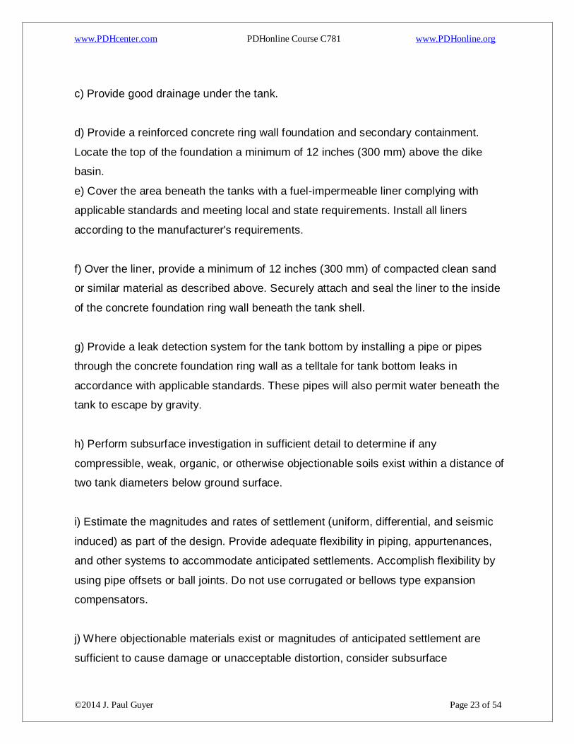
c) Provide good drainage under the tank.
d) Provide a reinforced concrete ring wall foundation and secondary containment.
Locate the top of the foundation a minimum of 12 inches (300 mm) above the dike
basin.
e) Cover the area beneath the tanks with a fuel-impermeable liner complying with
applicable standards and meeting local and state requirements. Install all liners
according to the manufacturer's requirements.
f) Over the liner, provide a minimum of 12 inches (300 mm) of compacted clean sand
or similar material as described above. Securely attach and seal the liner to the inside
of the concrete foundation ring wall beneath the tank shell.
g) Provide a leak detection system for the tank bottom by installing a pipe or pipes
through the concrete foundation ring wall as a telltale for tank bottom leaks in
accordance with applicable standards. These pipes will also permit water beneath the
tank to escape by gravity.
h) Perform subsurface investigation in sufficient detail to determine if any
compressible, weak, organic, or otherwise objectionable soils exist within a distance of
two tank diameters below ground surface.
i) Estimate the magnitudes and rates of settlement (uniform, differential, and seismic
induced) as part of the design. Provide adequate flexibility in piping, appurtenances,
and other systems to accommodate anticipated settlements. Accomplish flexibility by
using pipe offsets or ball joints. Do not use corrugated or bellows type expansion
compensators.
j) Where objectionable materials exist or magnitudes of anticipated settlement are
sufficient to cause damage or unacceptable distortion, consider subsurface

www.PDHcenter.com PDHonline Course C781 www.PDHonline.org
©2014 J. Paul Guyer Page 24 of 54
improvement. Potential improvement techniques may include removal of objectionable
materials and replacement with clean compacted granular fill, preloading or
surcharging in conjunction with drainage wicks, deep dynamic compaction,
vibrocompaction, stone columns, compaction grouting, or similar techniques.
k) Where justified by subsurface conditions and economics, consider using deep
foundations such as driven piling or drilled shafts.

www.PDHcenter.com PDHonline Course C781 www.PDHonline.org
©2014 J. Paul Guyer Page 25 of 54
9. UNDERGROUND HORIZONTAL STORAGE TANKS
9.1 GENERAL DESIGN CONSIDERATIONS. Where underground storage tanks of
50,000 gallon (191,000 L) or less capacity are required, use factory-built horizontal
cylindrical double-wall tanks (welded steel or fiberglass reinforced plastic (FRP)).
Ensure that contract requires the design and installation in accordance with 40 CFR
Part 280 and NFPA 30 or any more stringent state or local criteria. Require separation
of exterior tank walls from the interior walls with standoffs, thus creating an open
space, or interstitial, for monitoring of leaks. This is called a Type II tank. Do not
exceed 12 feet (3.7 m) in diameter for tanks. Limit tank length to eight times the
diameter. Ensure that factory-fabricated tanks comply with UL 58 and STI P3 criteria.
9.2 INSTALLATION.
a) Install tanks in accordance with NFPA 30 and also in strict accordance with the
manufacturer's installation instructions.
b) Install the tank so that the bottom slopes downward toward one end at a slope of 1
percent. Locate transfer pumps and suction piping at the low end of the tank.
c) Provide straps and anchors designed to prevent flotation of tanks located in areas
with high groundwater levels or subject to flooding. Provide electrical isolation strips
between hold-down straps and metal tanks. Anchors may be a concrete anchor slab
under the tank or concrete deadmen.
d) Place tanks on a uniform bed of homogeneous granular material at least 12 inches
(300 mm) thick. If a concrete anchor slab is used, place a minimum of 6 inches (150
mm) of bedding for steel tanks and 12 inches (300 mm) of bedding for fiberglass tanks
between the tank and the concrete anchor slab. Do not use blocks, chocks, or rocks.

www.PDHcenter.com PDHonline Course C781 www.PDHonline.org
©2014 J. Paul Guyer Page 26 of 54
e) Ensure that tank is installed by state-certified contractor if state has a certification
program.
f) Ensure that tank is installed by a contractor that is certified by the tank manufacturer.
10. UNDERGROUND VERTICAL STORAGE TANKS (CUT AND COVER)
10.1 GENERAL DESIGN CONSIDERATIONS. Underground vertical storage tanks
are steel-lined reinforced concrete with leak monitoring capability. These tanks may be
completely buried, surface-constructed and then covered with embankment, or any
variation in between. Design underground vertical steel storage tanks in accordance
with applicable standards, except as modified herein. These standards include tank
sizes of 10,000 through 100,000 barrels (1,600,000 L through 16,000,000 L) capacity.
In general, do not exceed 100,000 barrels (16,000,000 L) capacity. Alternative designs
using prefabricated/pre-stressed tank sections must be approved by the Owner.
Provide leak detection for underground storage tanks in accordance with federal,
state, and local regulations.
11. APPURTENANCES. Table 1 describes appurtenances for atmospheric storage
tanks and identifies the type of tank to which they should be mounted. Full seal weld
all tank attachments to prevent moisture/water from corroding the tank shell and
attachments.

www.PDHcenter.com PDHonline Course C781 www.PDHonline.org
©2014 J. Paul Guyer Page 27 of 54
12. HEATERS
12.1 GENERAL DESIGN CONSIDERATIONS. Provide tank heaters and controls for
tanks intended for storage of high viscosity products, such as lube oils, or burner fuels
No. 4, No. 5, and No. 6, in climates where the ambient tank temperature would be less
than 20 degrees F (11 degrees C) above the fuel’s pour point temperature. Heat heavy
burner fuel oils and lube oils to a temperature of 20 degrees F (11 degrees C) above
the fuel’s pour point prior to pumping. Use one of the types of heaters listed below.
12.2 HEATING MEDIUM. Use the appropriate heating medium for the particular
application based on temperature, pressure, and availability. Saturated steam is the
preferred heating medium, but consider using hot oil, hot water, and electric heating
where steam is not available from existing sources.
12.3 CONVECTION-TYPE. Use convection-type heaters installed inside a storage
tank and capable of passing through a 36-inch (900 mm) diameter manhole with a
capacity to raise the temperature of a full tank of burner fuel oil approximately 60
degrees F (33 degrees C) in 24 hours. The Owner will determine if the capacity of the
heater could be reduced if it is not necessary to heat a full tank of fuel within 24 hours.
12.4 IN-LINE TYPE. In-line heaters consist of two general types: tank suction and
straight tube. All in-line heaters are of the shell and tube construction. A tank suction
or suction in-line heater is installed inside the tank on the tank issue line. The fuel oil
enters the exchanger at the end within the tank and exits at the opposite end outside
of the tank. The steam or other heating medium enters and exits the exchanger at the
end outside of the tank. A straight tube or pipe in-line heater is installed directly into
the pipeline. The fuel oil enters the exchanger at one end and exits from the other. The
entry and exit points for the steam side can vary. The following criteria applies to in-
line heaters:

www.PDHcenter.com PDHonline Course C781 www.PDHonline.org
©2014 J. Paul Guyer Page 28 of 54
a) Capable of heating fuel oil passing through them from the ambient tank temperature
to a minimum of 20 degrees F (11 degrees C) above the fuel oil’s pour point
temperature at required flow rate.
b) If installed in tanks, allow removal of heater tube bundles without emptying the tank.
c) If multipass in-line heaters are used, do not allow the oil temperature rise to exceed
30 degrees F (17 degrees C) per pass.
d) Use carbon steel shells designed for a minimum 175 psig (1210 kPa) cold working
pressure on both steam and oil sides.
e) Do not exceed 0.2 psig (1.4 kPa) for the pressure drop on the oil side of pump
suction line nor exceed 10 psig (70 kPa) of pressure drop for heaters installed on
pump discharge.
12.5 INSULATION AND TRACING. In cases where fuels are heated, examine the
possible economic incentives for insulating heated storage vessels and piping. In
many cases, piping carrying heated products must be heat traced to prevent possible
solidification of the fuel during a shutdown period. Insulate traced lines. Consider
possible incentives for installing a condensate collection and return system. If a
condensate return system is installed, include a monitor to detect oil in the
condensate.

www.PDHcenter.com PDHonline Course C781 www.PDHonline.org
©2014 J. Paul Guyer Page 29 of 54
13. UNDERGROUND STORAGE TANK SPILL CONTAINMENT SYSTEMS
13.1 GENERAL DESIGN CONSIDERATIONS. Provide drainage structures to
impound escaping fuel where rupture of an underground tank in a hillside location
would endanger other activities and structures at elevations lower than the tank.
14. ABOVEGROUND TANK SPILL CONTAINMENT SYSTEMS
14.1 GENERAL DESIGN CONSIDERATIONS. Provide a spill containment system for
all aboveground tanks to prevent spilled petroleum from leaving the property.
Individual tanks larger than 10,000 barrels (1,600,000 L) in capacity should be
enclosed in an individual diked enclosure. Groups of tanks, with no tank larger than
10,000 barrels (1,600,000 L) and not exceeding 15,000 barrels (2,400,000 L) in
aggregate capacity, may be enclosed in a single diked enclosure. Subdivide each
diked area containing two or more tanks by intermediate curbs to prevent spills from
endangering adjacent tanks within the diked area. When subdividing is required, use
intermediate curbs not less than 18 inches (450 mm) in height. Designer can take
advantage of the exception granted for protected tanks by NFPA 30 or NFPA 30A if
the provisions of that document are met and local, state, and federal regulations
permit. Refer to DoD Standard Design AW 78-24-27. Use the following criteria for tank
spill containment systems:
a) The preferred method of containment is by diked enclosure (impounding spilled fuel
around the tank by means of dikes) to prevent the accidental discharge of petroleum.
b) As an alternative to diked enclosures, use a remote impoundment spill collection
system consisting of a series of drains leading from storage tank areas to a remote
containment or impoundment designed to prevent the accidental discharge of
petroleum. This is not the preferred method and requires approval of The Owner.
Generally, this system is used for tanks on a hillside.

www.PDHcenter.com PDHonline Course C781 www.PDHonline.org
©2014 J. Paul Guyer Page 30 of 54
c) Slope the area within the containment at no less than 1 percent to carry drainage
away from the tank to a sump located at the low point of the enclosure.
d) Construct the drain line from the sump of petroleum-resistant, fire-resistant,
impervious material. Do not use clay, concrete, fiberglass or plastic piping materials.
e) Control drainage from the sump to the outside of the enclosure by an eccentric plug
valve with indicator post located outside of the enclosure in an area that will be safely
accessible during a fire.
f) Do not allow fuel to run off or escape from the containment area under any
circumstances. Provide means for disposing or for treating contaminated water from
the containment to meet the most stringent of applicable federal, state, or local
requirements.
14.2 SPILL CONTAINMENT SYSTEM CAPACITY
14.2.1 DIKED ENCLOSURES. Design diked enclosures in accordance with the most
stringent of NFPA 30, 40 CFR Part 112, and other federal, state and local regulations.
Additionally, ensure that the capacity of the diked enclosure is, at a minimum, greater
than the largest tank volume located within the diked enclosure, plus sufficient
freeboard equal to the greater of a 24-hour, 25-year storm or one foot (0.3 m) over the
entire area of drainage \1\ or the flow of the water from firefighting activites /1/. In
appropriate environmental climates, consider snow and ice accumulation as well. Limit
dike heights to 6 feet (1.8 m) or less.
14.2.2 REMOTE IMPOUNDMENTS. If approved by the Owner, design remote
impoundments in accordance with the most stringent of NFPA 30, 40 CFR Part 112,
and other federal, state and local regulations. Additionally, ensure the capacity of the
remote impoundment is, at a minimum, greater than the largest tank volume located
within the area of drainage or the flow of water from firefighting activities on
www.PDHcenter.com PDHonline Course C781 www.PDHonline.org
©2014 J. Paul Guyer Page 31 of 54
neighboring storage tanks sharing the same spill collection system /1/, plus sufficient
freeboard equal to the greater of a 24-hour, 25-year storm or one foot (0.3 m) over the
entire area of drainage. When sizing the remote impoundment consider the total
drainage area from all tanks that are included within the spill collection system. In
appropriate environmental climates, consider snow and ice accumulation as well.
14.3 REMOTE CONTAINMENT/IMPOUNDMENT SPILL COLLECTION SYSTEMS.
Construct the remote impoundment as generally described for diked enclosures.
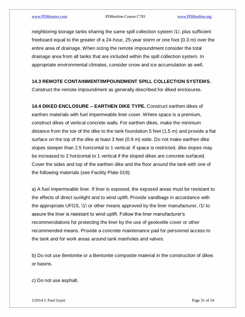
14.4 DIKED ENCLOSURE – EARTHEN DIKE TYPE. Construct earthen dikes of
earthen materials with fuel impermeable liner cover. Where space is a premium,
construct dikes of vertical concrete walls. For earthen dikes, make the minimum
distance from the toe of the dike to the tank foundation 5 feet (1.5 m) and provide a flat
surface on the top of the dike at least 3 feet (0.9 m) wide. Do not make earthen dike
slopes steeper than 2.5 horizontal to 1 vertical. If space is restricted, dike slopes may
be increased to 2 horizontal to 1 vertical if the sloped dikes are concrete surfaced.
Cover the sides and top of the earthen dike and the floor around the tank with one of
the following materials (see Facility Plate 019):
a) A fuel impermeable liner. If liner is exposed, the exposed areas must be resistant to
the effects of direct sunlight and to wind uplift. Provide sandbags in accordance with
the appropriate UFGS, \1\ or other means approved by the liner manufacturer, /1/ to
assure the liner is resistant to wind uplift. Follow the liner manufacturer’s
recommendations for protecting the liner by the use of geotextile cover or other
recommended means. Provide a concrete maintenance pad for personnel access to
the tank and for work areas around tank manholes and valves.
b) Do not use Bentonite or a Bentonite composite material in the construction of dikes
or basins.
c) Do not use asphalt.

www.PDHcenter.com PDHonline Course C781 www.PDHonline.org
©2014 J. Paul Guyer Page 32 of 54
14.5 DIKED ENCLOSURE – REINFORCED CONCRETE DIKE TYPE. Design
reinforced concrete (prefabricated or cast-in-place) dikes and their foundations to
resist and contain the full hydrostatic load when filled to capacity. Consider the use of
reinforced concrete blocks with or without exterior earth mounding. Use vertical
reinforced concrete dikes where space is a premium. Seal all concrete surfaces with a
flexible, UV-resistant, fuel-resistant coating if required by local or State regulations.
Use a fuel impermeable liner as described above for the dike floor.
14.6 DIKED ENCLOSURE – COMBINATION DIKE TYPE. A vertical concrete wall
backed by an external earthen berm may be used. Design the combined earthen and
concrete unit and its foundation to resist and contain the full hydrostatic load when
filled to capacity. Use a fuel impermeable liner as described above for the dike floor.
14.7 STORMWATER COLLECTION SYSTEMS. Design a stormwater collection
system to contain, transport, treat, and discharge any stormwater that collects in the
tank enclosure. Review state and local regulations for design requirements and
permitting of stormwater treatment systems.
14.8 DIKE ACCESS. Provide concrete, steel, or aluminum steps with pipe handrails
for passage across a dike. Steps and handrails must comply with 29 CFR Part
1910.36. Include a removable section of the handrail to provide access to the flat top
of earthen dikes. If steel steps are used, they should be hot-dipped galvanized after
fabrication. Provide enough access locations for safe emergency egress and for
normal operation. This will normally include steps over the dikes separating adjacent
tanks, as well as on one wall without an adjacent tank. Locate steps at the most
accessible points, preferably on the same side as the access stairs to a tank roof. For
tanks \1\ /1/ 10,000 barrels (1,600,000 L) and larger, consider providing earth-filled
ramps to permit vehicle access into the dike when approved by The Owner. If there is
sufficient need to provide vehicle access into diked areas, provide a concrete paved
road and/or earth-filled ramp for vehicle travel-ways. A removable steel bulkhead

www.PDHcenter.com PDHonline Course C781 www.PDHonline.org
©2014 J. Paul Guyer Page 33 of 54
section may be a cost-effective method to provide access for dikes with vertical
reinforced concrete walls. Where the vehicle access road crosses the dike, provide a
security gate and prominent sign indicating that access is limited to a 1-ton pick-up
truck that is compliant with NFPA 70 Class I, Group D, Division 2 criteria.

www.PDHcenter.com PDHonline Course C781 www.PDHonline.org
©2014 J. Paul Guyer Page 34 of 54
15. MISCELLANEOUS USE TANKS. This paragraph provides design guidance for
miscellaneous use tanks. These tanks are typically less than 550 gallons (2,100 L) in
capacity. Check state and local regulations before beginning design. If a
miscellaneous use tank has a capacity greater than 12,000 gallons (45,800 L), follow
the requirements of Table 1. Otherwise, use the standards described below.
15.1 INSTALLATION. Install the tank in conformance with the requirements of NFPA
30. The exception used for the deletion of dike containment is acceptable if all of the
criteria associated with that exception are met. Provide containment for all tanks,
regardless of size, except small residential heating oil tanks, by complying with the
paragraph titled “Aboveground Tank Spill Containment Systems” in this chapter of this
UFC or by using properly installed aboveground concrete-encased tanks in
accordance with the paragraph titled “Horizontal Aboveground Tanks (Protected
Tanks)”.
15.2 HEATING OIL TANKS. Comply with NFPA 31.
15.3 GENERATOR FUEL TANKS. Comply with NFPA 31, NFPA 37, and NFPA 110.
15.4 FIRE PUMP FUEL TANKS. Comply with NFPA 20, NFPA 30, and NFPA 31.
15.5 WASTE OIL TANKS. Check local and state environmental regulations for any
additional requirements for storage of waste oil.
15.6 CONTAINMENT. As discussed previously in this chapter, provide containment,
under and around all aboveground tanks except home heating oil tanks.
15.7 UNDERGROUND TANKS. Ensure all underground tanks are double-walled and
have overfill protection, as described previously.

www.PDHcenter.com PDHonline Course C781 www.PDHonline.org
©2014 J. Paul Guyer Page 35 of 54
16. SHIPBOARD OFF-LOAD FUEL STORAGE TANKS
16.1 FUNCTION. In addition to regular storage, consider a storage tank for fuel
removed from ships that may be off-specification or otherwise not satisfactory for its
intended use. This fuel may be downgraded to heating oil or diesel fuel marine.
16.2 GENERAL DESIGN CONSIDERATIONS. Determine the volume requirements of
the contaminated fuel storage tank by an activity survey. Provide bottom-loading
facilities for tank truck loading and off-loading of contaminated fuel.
16.3 LOCATIONS. Locate the contaminated fuel storage tank(s) in or near the facility
tank farm. Clearly mark the tank(s) as to the type or grade of fuel.
17. JET ENGINE TEST CELL FUEL STORAGE TANKS. Design jet engine test cell
fuel storage and issue systems to the same standards as operating storage tank fuel
systems (e.g., high level alarms, gauging, shut-offs, etc.). Normally, tanks are refilled
using station aircraft refueling trucks through aircraft single-point refueling adaptors.

www.PDHcenter.com PDHonline Course C781 www.PDHonline.org
©2014 J. Paul Guyer Page 36 of 54
Table 1
Appurtenances
V-A = Vertical Aboveground Storage Tank H-A = Horizontal Aboveground Storage Tank H-U = Horizontal Underground Storage Tank F-A = Fire-Resistant Aboveground Storage Tank P-A = Protected Aboveground Storage Tank V-U = Vertical Underground Storage Tank

www.PDHcenter.com PDHonline Course C781 www.PDHonline.org
©2014 J. Paul Guyer Page 37 of 54
Table 1 (continued)
Appurtenances

www.PDHcenter.com PDHonline Course C781 www.PDHonline.org
©2014 J. Paul Guyer Page 38 of 54
Table 1 (continued)
Appurtenances

www.PDHcenter.com PDHonline Course C781 www.PDHonline.org
©2014 J. Paul Guyer Page 39 of 54
Table 1 (continued)
Appurtenances

www.PDHcenter.com PDHonline Course C781 www.PDHonline.org
©2014 J. Paul Guyer Page 40 of 54
Table 1 (continued)
Appurtenances

www.PDHcenter.com PDHonline Course C781 www.PDHonline.org
©2014 J. Paul Guyer Page 41 of 54
Table 1 (continued)
Appurtenances

www.PDHcenter.com PDHonline Course C781 www.PDHonline.org
©2014 J. Paul Guyer Page 42 of 54
Table 1 (continued)
Appurtenances

www.PDHcenter.com PDHonline Course C781 www.PDHonline.org
©2014 J. Paul Guyer Page 43 of 54
Figure 1
www.PDHcenter.com PDHonline Course C781 www.PDHonline.org
©2014 J. Paul Guyer Page 44 of 54
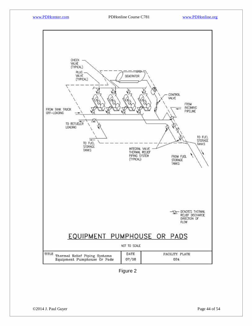
Figure 2

www.PDHcenter.com PDHonline Course C781 www.PDHonline.org
©2014 J. Paul Guyer Page 45 of 54
Figure 3

www.PDHcenter.com PDHonline Course C781 www.PDHonline.org
©2014 J. Paul Guyer Page 46 of 54
Figure 4

www.PDHcenter.com PDHonline Course C781 www.PDHonline.org
©2014 J. Paul Guyer Page 47 of 54
Figure 5

www.PDHcenter.com PDHonline Course C781 www.PDHonline.org
©2014 J. Paul Guyer Page 48 of 54
Figure 6
www.PDHcenter.com PDHonline Course C781 www.PDHonline.org
©2014 J. Paul Guyer Page 49 of 54
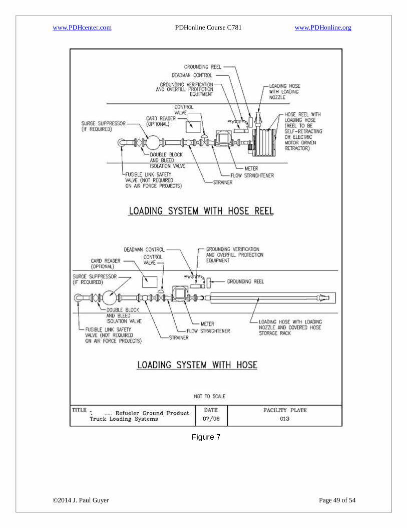
Figure 7

www.PDHcenter.com PDHonline Course C781 www.PDHonline.org
©2014 J. Paul Guyer Page 50 of 54
Figure 8

www.PDHcenter.com PDHonline Course C781 www.PDHonline.org
©2014 J. Paul Guyer Page 51 of 54
Figure 9
www.PDHcenter.com PDHonline Course C781 www.PDHonline.org
©2014 J. Paul Guyer Page 52 of 54
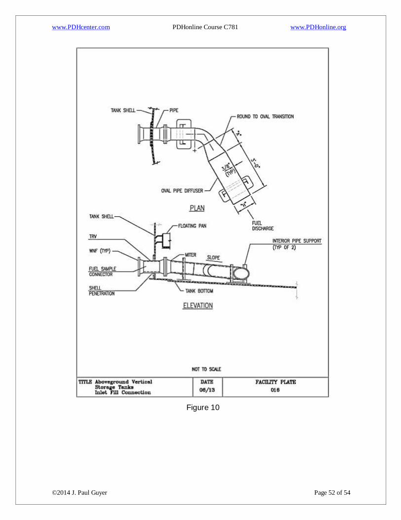
Figure 10

www.PDHcenter.com PDHonline Course C781 www.PDHonline.org
©2014 J. Paul Guyer Page 53 of 54
Figure 11
www.PDHcenter.com PDHonline Course C781 www.PDHonline.org
©2014 J. Paul Guyer Page 54 of 54
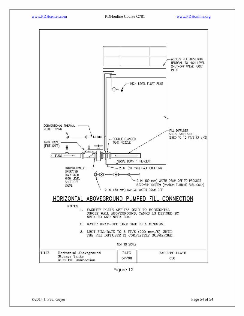
Figure 12