Embed Size (px)
Citation preview
An introduction to electric motors
Mechanical
energy
What is an electric motor
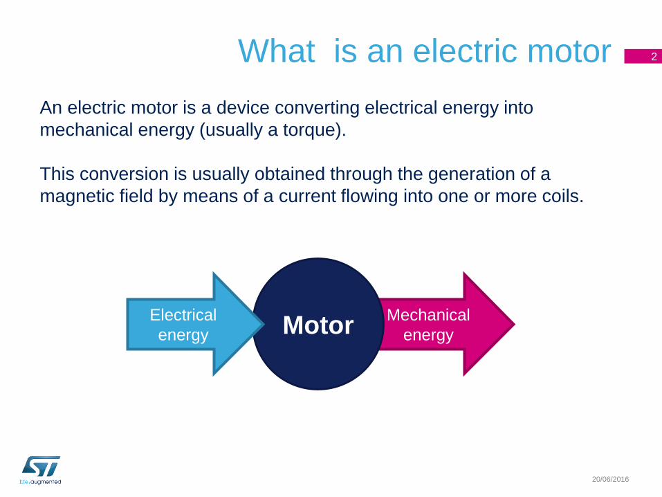
An electric motor is a device converting electrical energy into
mechanical energy (usually a torque).
This conversion is usually obtained through the generation of a
magnetic field by means of a current flowing into one or more coils.
2
20/06/2016
MotorElectrical
energy
Rotor and stator magnetic fields 3
20/06/2016
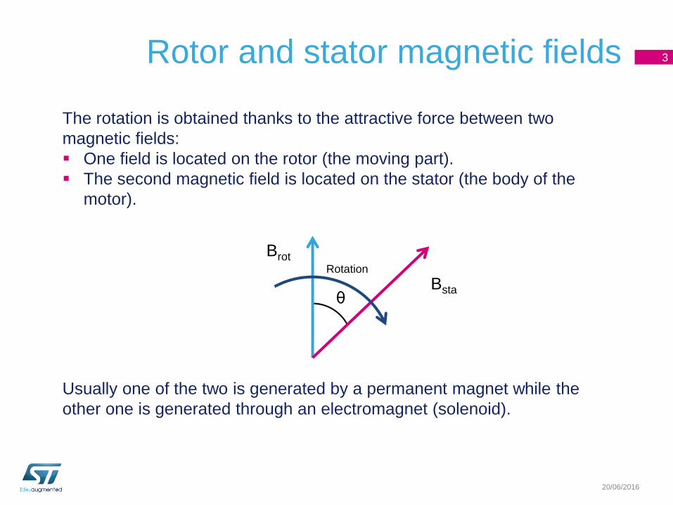
The rotation is obtained thanks to the attractive force between two
magnetic fields:
One field is located on the rotor (the moving part).
The second magnetic field is located on the stator (the body of the
motor).
Bsta
Brot
θ
Rotation
Usually one of the two is generated by a permanent magnet while the
other one is generated through an electromagnet (solenoid).
Magnetic field generation 4
20/06/2016
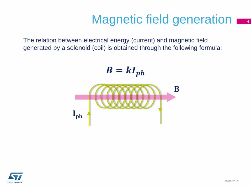
The relation between electrical energy (current) and magnetic field
generated by a solenoid (coil) is obtained through the following formula:
𝑩 = 𝒌𝑰𝒑𝒉
B
Iph
Torque 5
20/06/2016
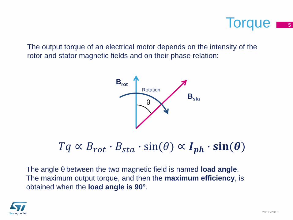
The output torque of an electrical motor depends on the intensity of the
rotor and stator magnetic fields and on their phase relation:
Bsta
Brot
θ
Rotation
𝑇𝑞 ∝ 𝐵𝑟𝑜𝑡 ∙ 𝐵𝑠𝑡𝑎 ∙ sin(𝜃) ∝ 𝑰𝒑𝒉 ∙ 𝐬𝐢𝐧(𝜽)
The angle θ between the two magnetic field is named load angle.
The maximum output torque, and then the maximum efficiency, is
obtained when the load angle is 90°.
Back electro-motive force 6
20/06/2016
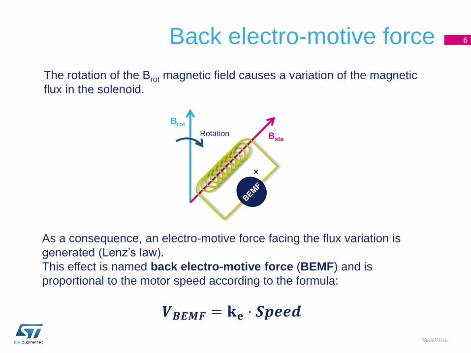
The rotation of the Brot magnetic field causes a variation of the magnetic
flux in the solenoid.
As a consequence, an electro-motive force facing the flux variation is
generated (Lenz’s law).
This effect is named back electro-motive force (BEMF) and is
proportional to the motor speed according to the formula:
Bsta
Brot
Rotation
𝑽𝑩𝑬𝑴𝑭 = 𝐤𝐞 ⋅ 𝑺𝒑𝒆𝒆𝒅
Basic principle
The electric motor operation is based on the following points:
• At least one of the two magnetic field is generated by a solenoid
carrying a current.
• The phase relation between the rotor and stator magnetic field (i.e.
the load angle) must be always greater than 0° in order to keep the
motor in motion (negative angles reverse the rotation).
• Output torque depends on both the solenoid current and load angle.
• Motor rotation causes a back electro-motive force opposing the
motion itself.
7
20/06/2016
Brush DC motor
20/06/2016

N S
A
A
D D
Brush DC motor basics 9
20/06/2016
The rotor is composed
of a group of coils
The stator
magnetic field is
generated by a
permanent
magnet
The rotor coils are
sequentially
connected to the
motor leads through
mechanical
switches (brushes)
Brush DC motor basics 10
20/06/2016
N S
A
A
D D
Brot
Bsta
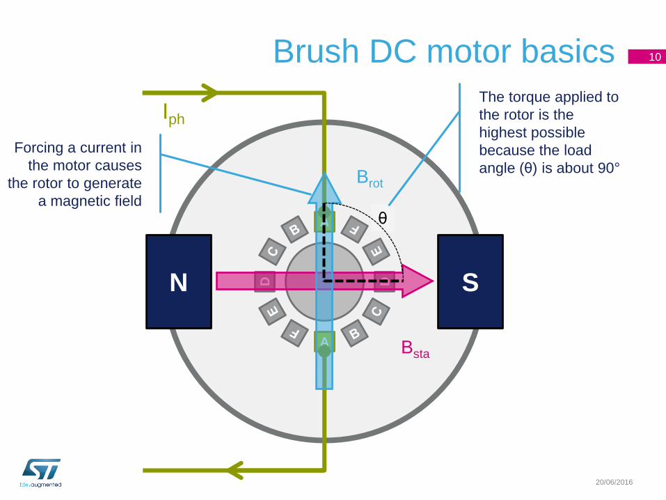
Iph
θ
Forcing a current in
the motor causes
the rotor to generate
a magnetic field
The torque applied to
the rotor is the
highest possible
because the load
angle (θ) is about 90°
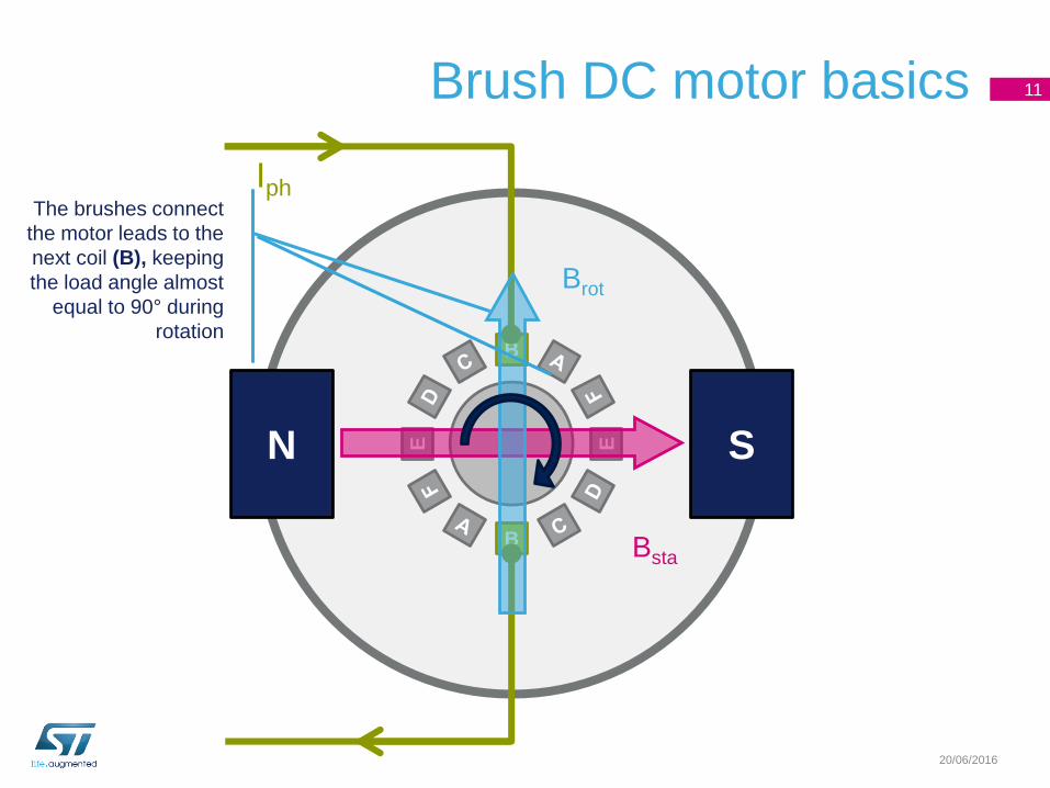
Brush DC motor basics 11
20/06/2016
11
N S
B
B
E E
Brot
Bsta
IphThe brushes connect
the motor leads to the
next coil (B), keeping
the load angle almost
equal to 90° during
rotation
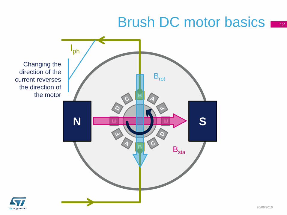
Brush DC motor basics 12
20/06/2016
12
N S
B
B
E E
Brot
Bsta
Iph
Changing the
direction of the
current reverses
the direction of
the motor
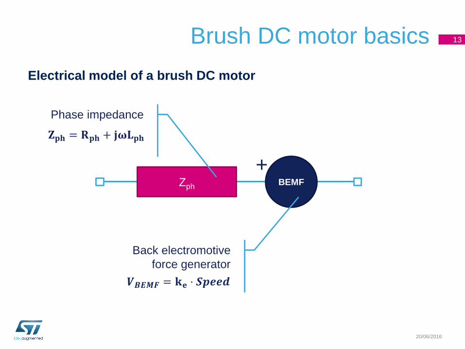
Brush DC motor basics
Electrical model of a brush DC motor
13
20/06/2016
ZphBEMF
+
Phase impedance
Back electromotive
force generator
𝐙𝐩𝐡 = 𝐑𝐩𝐡 + 𝐣𝛚𝐋𝐩𝐡
𝑽𝑩𝑬𝑴𝑭 = 𝐤𝐞 ⋅ 𝑺𝒑𝒆𝒆𝒅
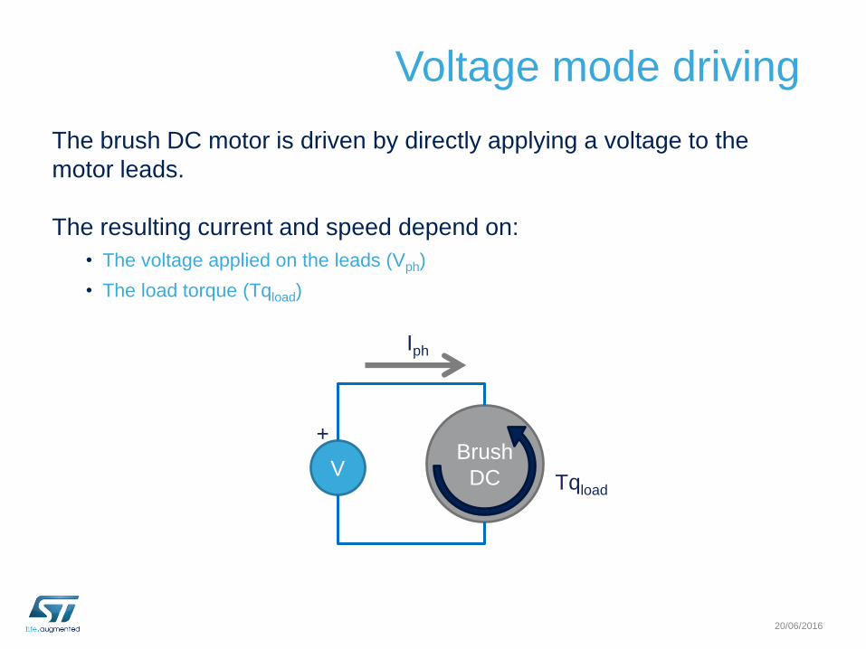
Voltage mode driving
The brush DC motor is driven by directly applying a voltage to the
motor leads.
The resulting current and speed depend on:
• The voltage applied on the leads (Vph)
• The load torque (Tqload)
20/06/2016
Brush
DCV
+
Iph
Tqload
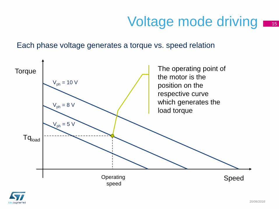
Voltage mode driving 15
20/06/2016
Vph = 10 V
Vph = 8 V
Vph = 5 V
Speed
Torque
Tqload
Operating
speed
The operating point of
the motor is the
position on the
respective curve
which generates the
load torque
Each phase voltage generates a torque vs. speed relation
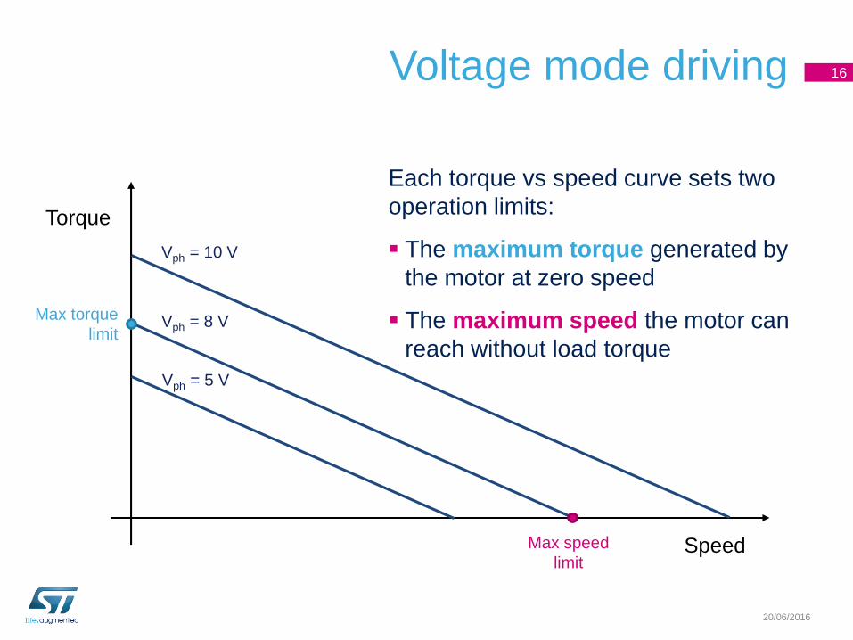
Voltage mode driving 16
20/06/2016
Vph = 10 V
Vph = 8 V
Vph = 5 V
Speed
Torque
Max torque
limit
Max speed
limit
Each torque vs speed curve sets two
operation limits:
The maximum torque generated by
the motor at zero speed
The maximum speed the motor can
reach without load torque
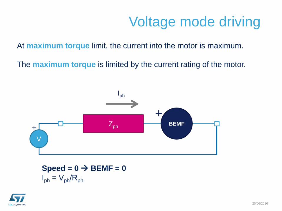
Voltage mode driving
At maximum torque limit, the current into the motor is maximum.
The maximum torque is limited by the current rating of the motor.
20/06/2016
V
+
Iph
Speed = 0 BEMF = 0
Iph = Vph/Rph
ZphBEMF
+
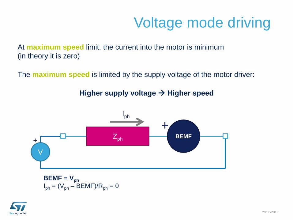
Voltage mode driving
At maximum speed limit, the current into the motor is minimum
(in theory it is zero)
The maximum speed is limited by the supply voltage of the motor driver:
Higher supply voltage Higher speed
20/06/2016
V
+
Iph
BEMF = Vph
Iph = (Vph – BEMF)/Rph = 0
ZphBEMF
+
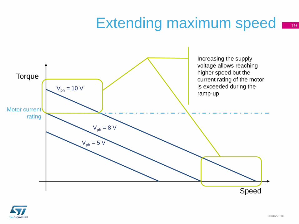
Extending maximum speed 19
20/06/2016
Vph = 10 V
Vph = 8 V
Vph = 5 V
Speed
Torque
Motor current
rating
Increasing the supply
voltage allows reaching
higher speed but the
current rating of the motor
is exceeded during the
ramp-up
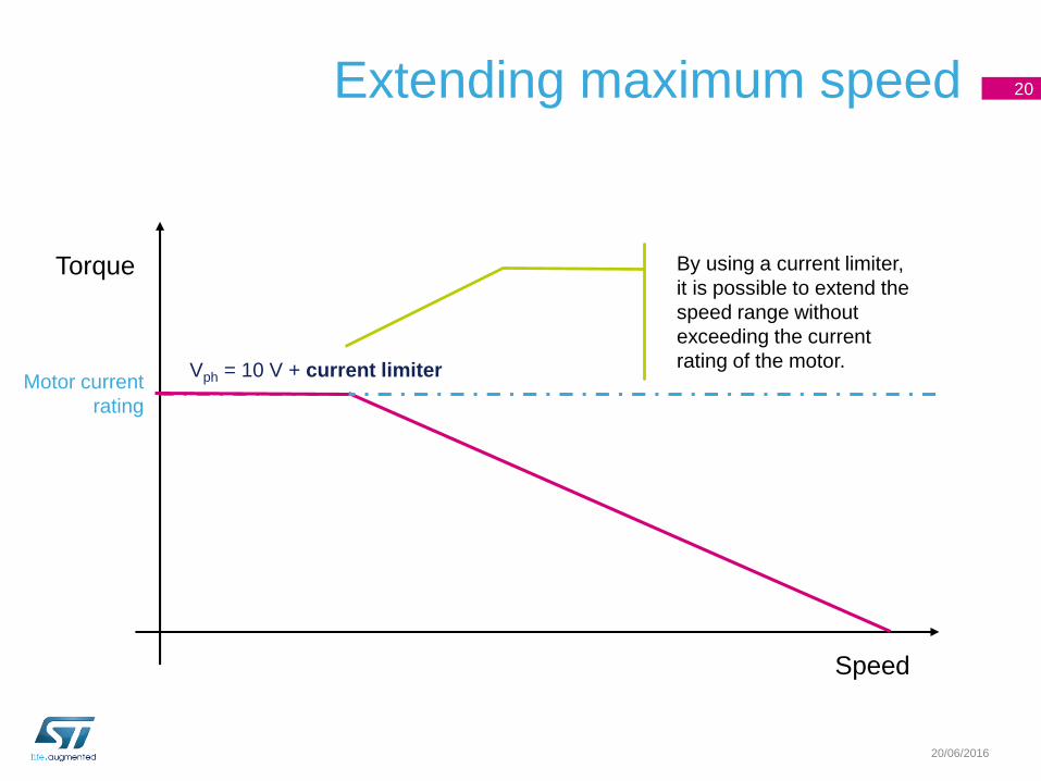
Extending maximum speed 20
20/06/2016
Vph = 10 V + current limiter
Speed
Torque
Motor current
rating
By using a current limiter,
it is possible to extend the
speed range without
exceeding the current
rating of the motor.
Brush DC motor summary
• The magnetic field intensity is proportional to the current forced into the motor leads.
• The magnetic field rotation is automatically obtained commutating the active coil
through mechanical switches (brushes).
• The load angle is almost constant and it is about 90° allowing the maximum efficiency
(current vs. torque proportion).
• The motor is controlled by applying a voltage to the motor leads. The higher the
voltage, the higher the speed. The direction is changed by reversing the polarity on the
leads.
• The maximum torque is limited by the current rating of the motor and it is obtained at
zero speed (start-up).
• The maximum speed is limited by the supply voltage and it is obtained when no load
torque is present.
21
20/06/2016

Three-phase brushless motor
20/06/2016
Brushless motors overview
There are different types of brushless motors:
• Single-phase
• Two-phase
• Three-phase
The presentation will describe the basics of the three-phase
brushless motor because it is the most common version.
In most cases, the considerations can be extended to the other types.
20/06/2016
SN
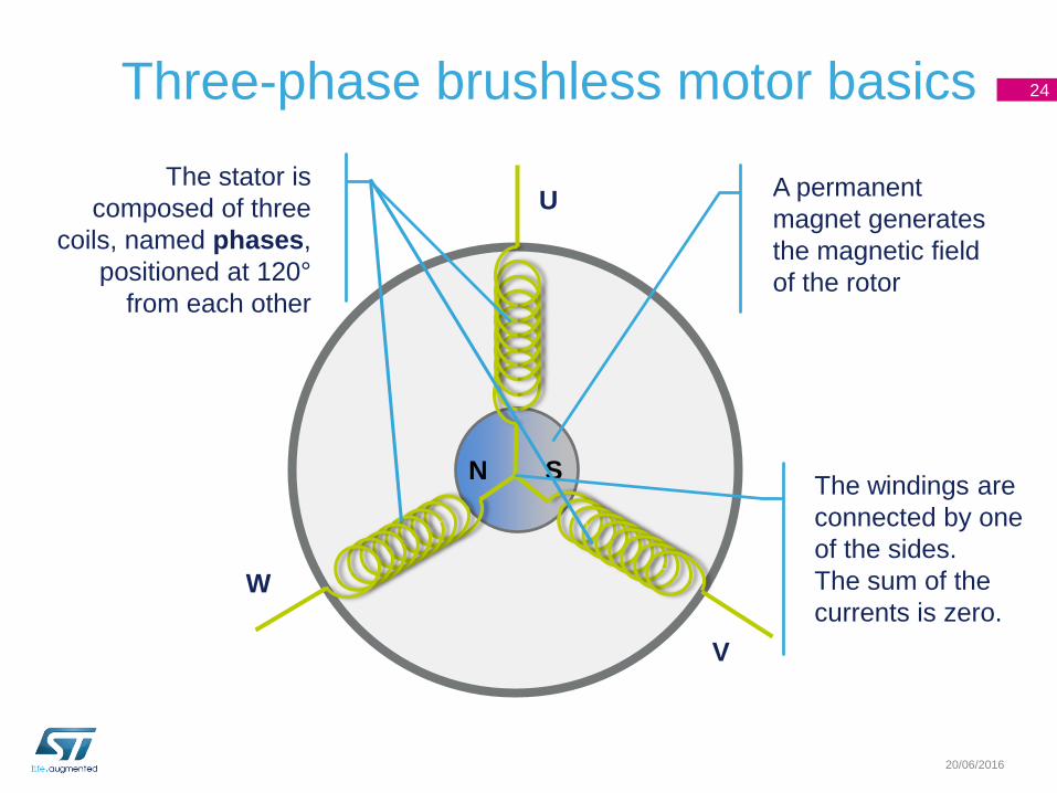
Three-phase brushless motor basics 24
20/06/2016
A permanent
magnet generates
the magnetic field
of the rotor
The stator is
composed of three
coils, named phases,
positioned at 120°
from each other
The windings are
connected by one
of the sides.
The sum of the
currents is zero.
U
V
W
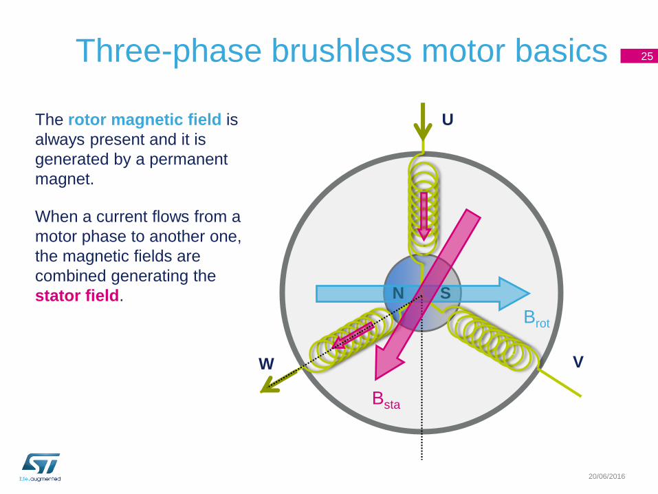
Three-phase brushless motor basics 25
20/06/2016
The rotor magnetic field is
always present and it is
generated by a permanent
magnet.
When a current flows from a
motor phase to another one,
the magnetic fields are
combined generating the
stator field. SN
Brot
Bsta
U
VW

20/06/2016
SN
Brot
Bsta
The torque applied to the
motor is proportional to the
sine of the load angle (θ).
When the rotor magnetic field
approaches the stator one, the
torque is reduced.
In order to keep the motor in
motion, it is necessary to
change the direction of the
stator magnetic field.
U
VW
Three-phase brushless motor basics 26
θ
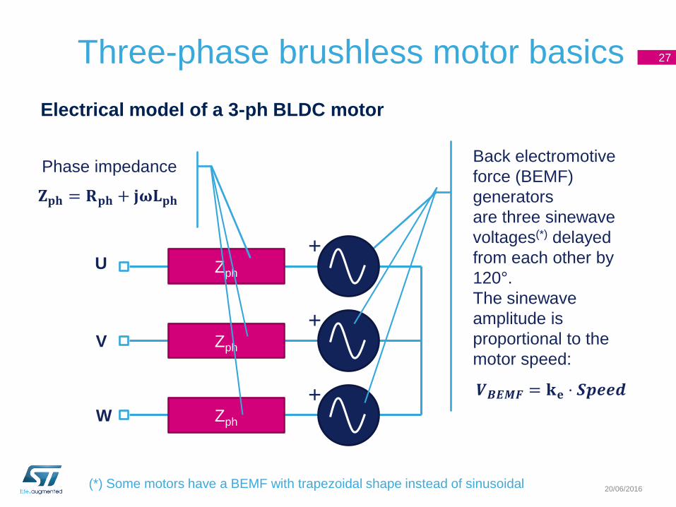
Back electromotive
force (BEMF)
generators
are three sinewave
voltages(*) delayed
from each other by
120°.
The sinewave
amplitude is
proportional to the
motor speed:
Three-phase brushless motor basics
Electrical model of a 3-ph BLDC motor
27
20/06/2016
Zph
+
Zph
+
Zph
+
Phase impedance
𝐙𝐩𝐡 = 𝐑𝐩𝐡 + 𝐣𝛚𝐋𝐩𝐡
𝑽𝑩𝑬𝑴𝑭 = 𝐤𝐞 ⋅ 𝑺𝒑𝒆𝒆𝒅
U
V
W
(*) Some motors have a BEMF with trapezoidal shape instead of sinusoidal
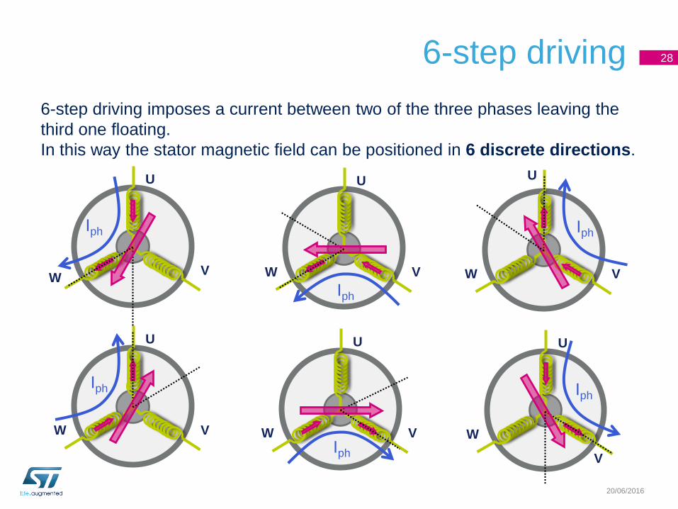
6-step driving
6-step driving imposes a current between two of the three phases leaving the
third one floating.
In this way the stator magnetic field can be positioned in 6 discrete directions.
28
20/06/2016
U
VW
U
VW
U
VW
U
VW
U
V
W
U
VW
Iph
Iph
Iph
Iph
Iph Iph
6-step driving
The scanning of the 6 driving combinations of the six steps
is synchronized by the rotor position.
The rotor position can be monitored using Hall sensors or a
BEMF sensing technique (sensorless).
29
20/06/2016
6-step driving 30
20/06/2016
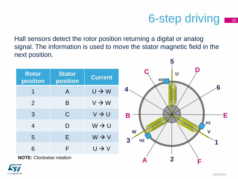
Rotor
position
Stator
positionCurrent
1 A U W
2 B V W
3 C V U
4 D W U
5 E W V
6 F U V
Hall sensors detect the rotor position returning a digital or analog
signal. The information is used to move the stator magnetic field in the
next position.
U
VW
H1
H3
H2 1
2
3
4
5
6
NOTE: Clockwise rotationA
B
C D
E
F
6-step driving 31
20/06/2016
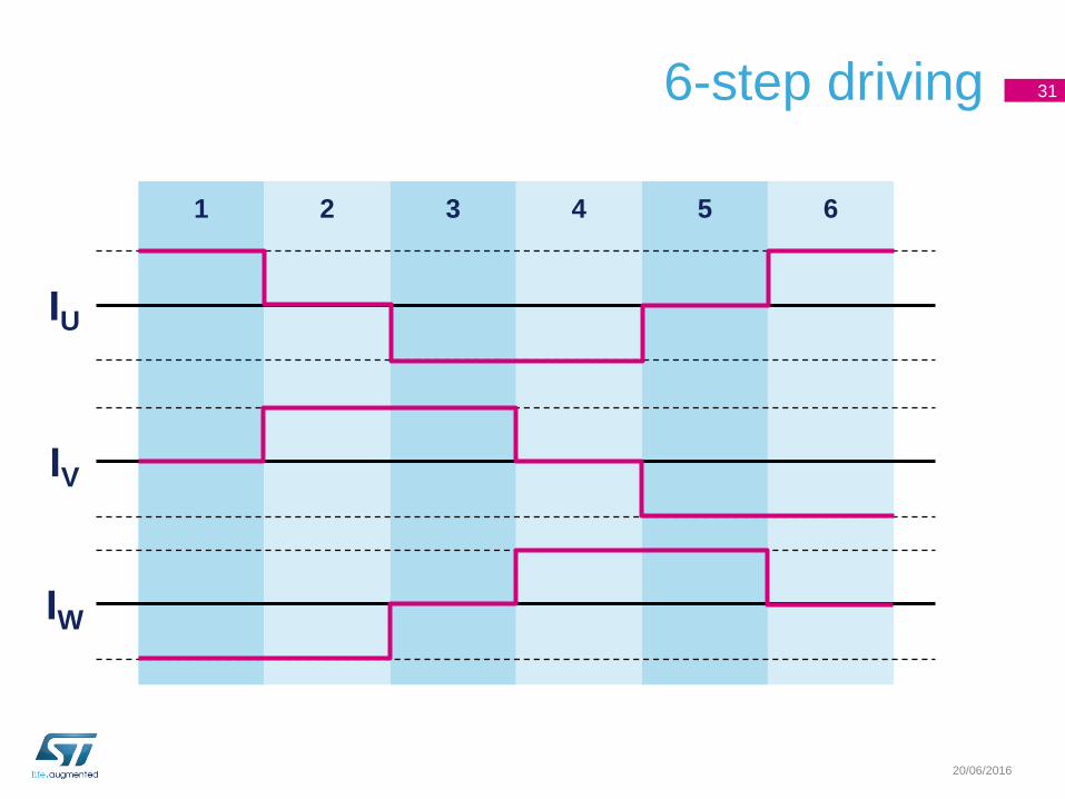
1 2 3 4 5 6
IU
IV
IW
6-step driving 32
20/06/2016
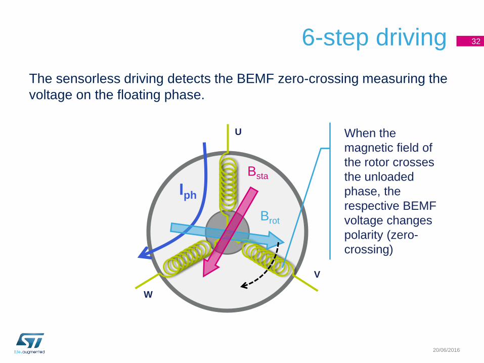
The sensorless driving detects the BEMF zero-crossing measuring the
voltage on the floating phase.
U
V
W
Iph
Brot
Bsta
When the
magnetic field of
the rotor crosses
the unloaded
phase, the
respective BEMF
voltage changes
polarity (zero-
crossing)
6-step driving 33
20/06/2016
Zph
+
Zph
+
Zph
+
U
V
W
VCenter
Iph
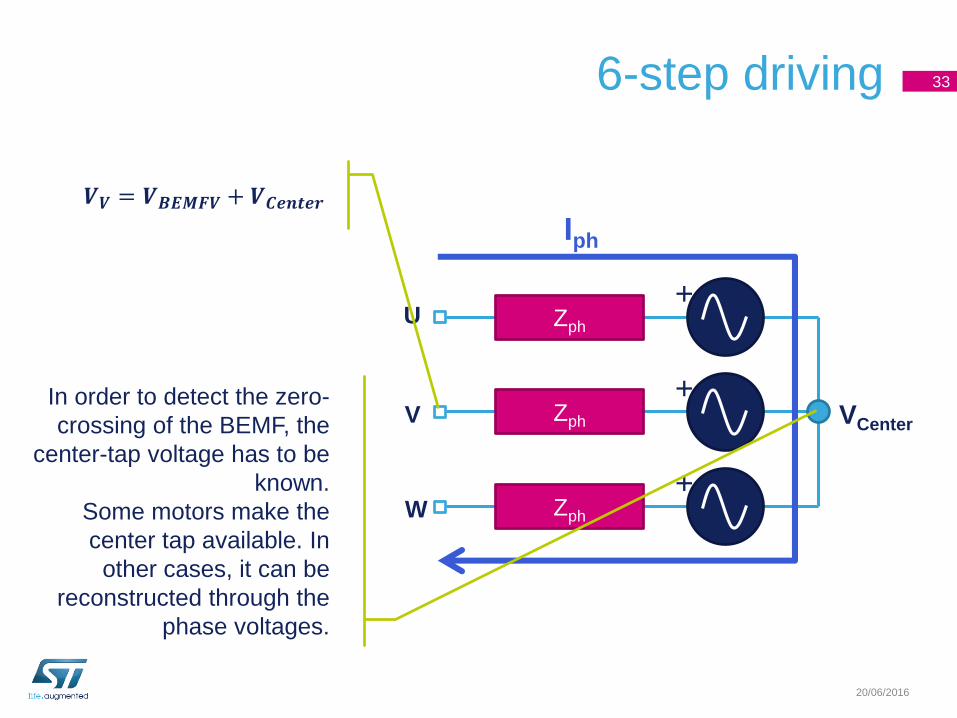
In order to detect the zero-
crossing of the BEMF, the
center-tap voltage has to be
known.
Some motors make the
center tap available. In
other cases, it can be
reconstructed through the
phase voltages.
𝑽𝑽 = 𝑽𝑩𝑬𝑴𝑭𝑽 + 𝑽𝑪𝒆𝒏𝒕𝒆𝒓
20/06/2016
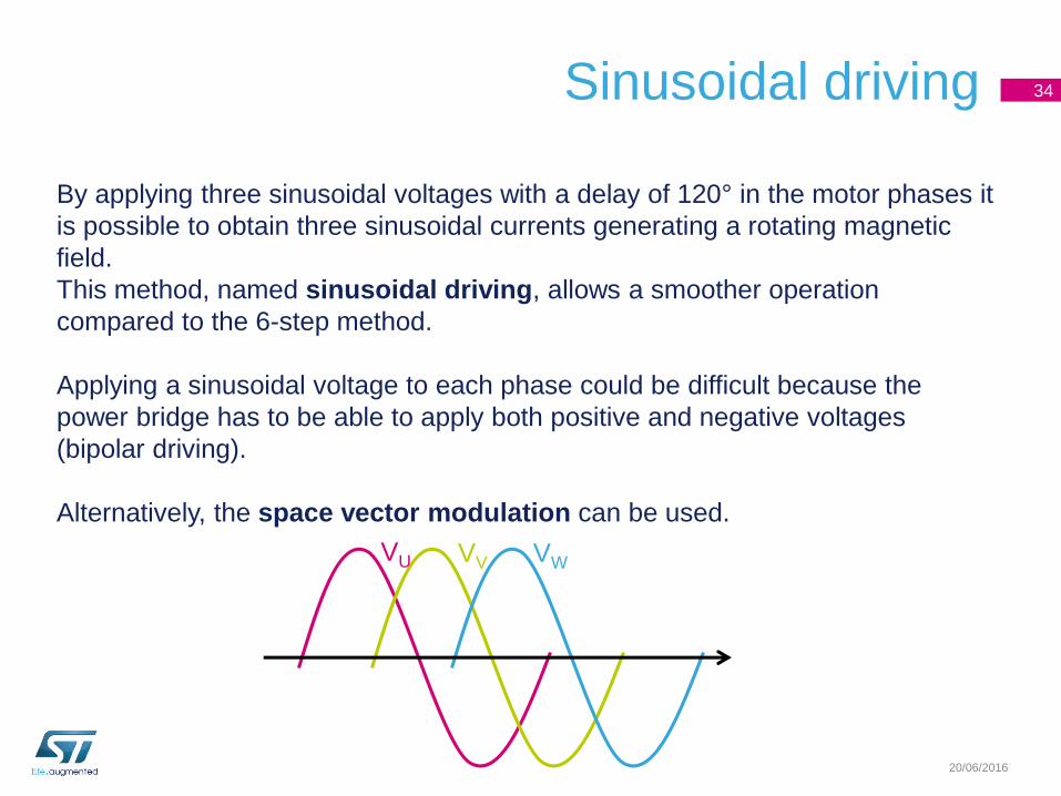
By applying three sinusoidal voltages with a delay of 120° in the motor phases it
is possible to obtain three sinusoidal currents generating a rotating magnetic
field.
This method, named sinusoidal driving, allows a smoother operation
compared to the 6-step method.
Applying a sinusoidal voltage to each phase could be difficult because the
power bridge has to be able to apply both positive and negative voltages
(bipolar driving).
Alternatively, the space vector modulation can be used.
Sinusoidal driving 34
VU VV VW
20/06/2016
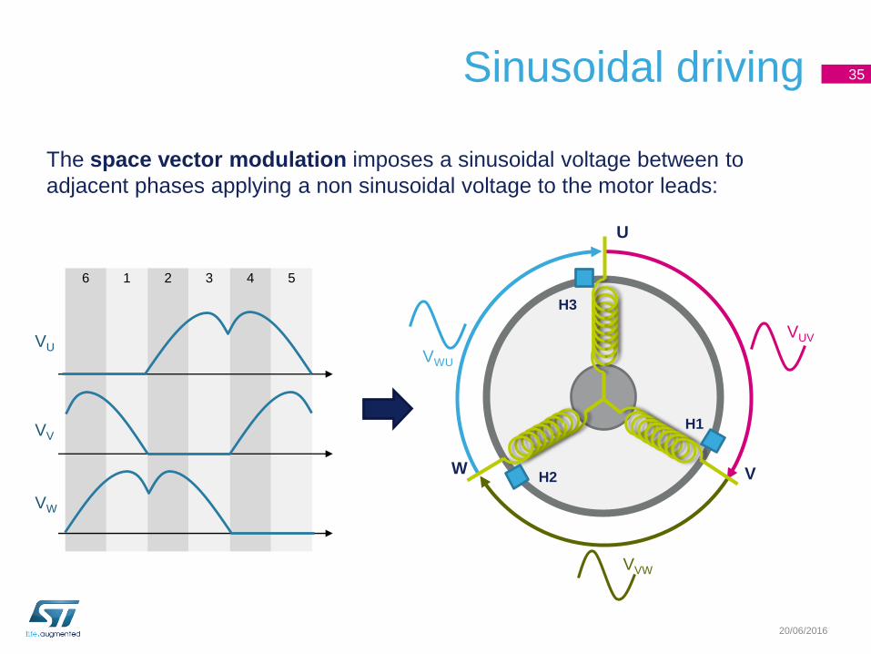
The space vector modulation imposes a sinusoidal voltage between to
adjacent phases applying a non sinusoidal voltage to the motor leads:
Sinusoidal driving 35
VU
VV
VW
6 1 2 3 4 5
VUV
VVW
VWU
U
VW
H1
H3
H2
20/06/2016
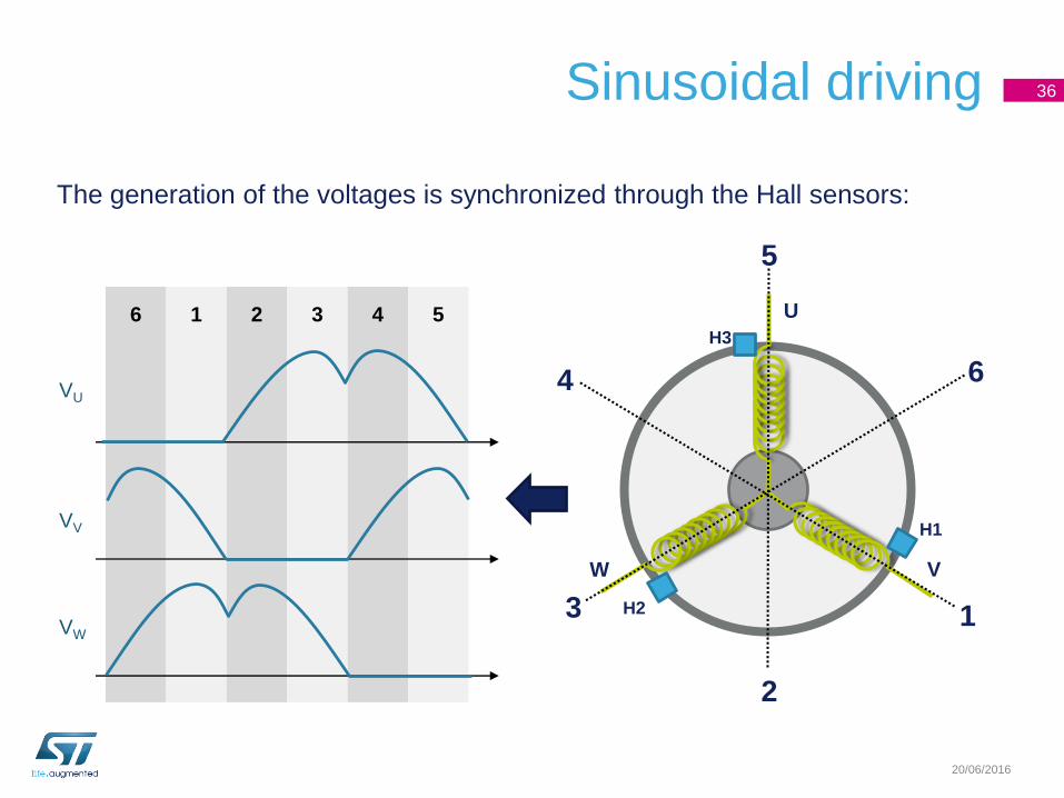
The generation of the voltages is synchronized through the Hall sensors:
Sinusoidal driving 36
VU
VV
VW
6 1 2 3 4 5 U
VW
H1
H3
H2 1
2
3
4
5
6
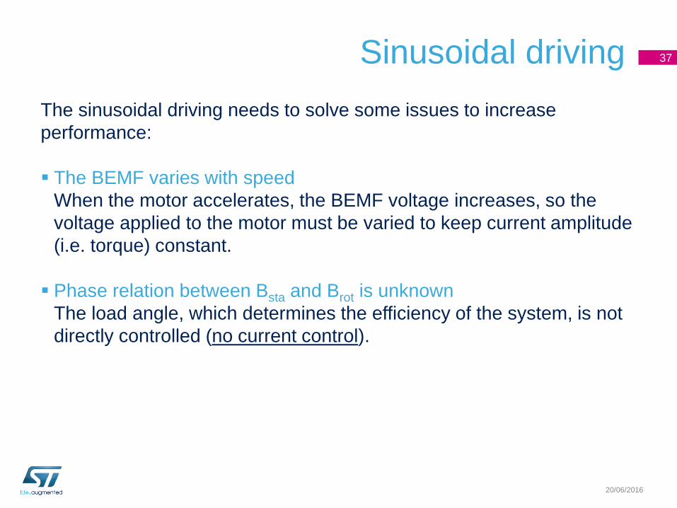
Sinusoidal driving
The sinusoidal driving needs to solve some issues to increase
performance:
The BEMF varies with speed
When the motor accelerates, the BEMF voltage increases, so the
voltage applied to the motor must be varied to keep current amplitude
(i.e. torque) constant.
Phase relation between Bsta and Brot is unknown
The load angle, which determines the efficiency of the system, is not
directly controlled (no current control).
37
20/06/2016
Field Oriented Control 38
20/06/2016
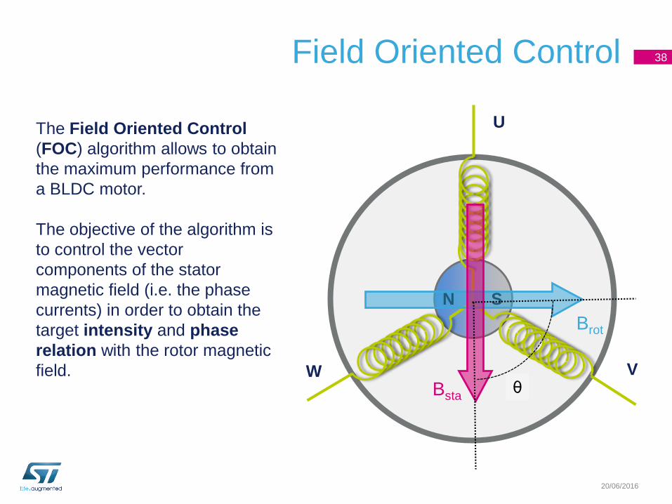
The Field Oriented Control
(FOC) algorithm allows to obtain
the maximum performance from
a BLDC motor.
The objective of the algorithm is
to control the vector
components of the stator
magnetic field (i.e. the phase
currents) in order to obtain the
target intensity and phase
relation with the rotor magnetic
field.
SN
Brot
Bsta
U
VWθ
Field Oriented Control 39
20/06/2016
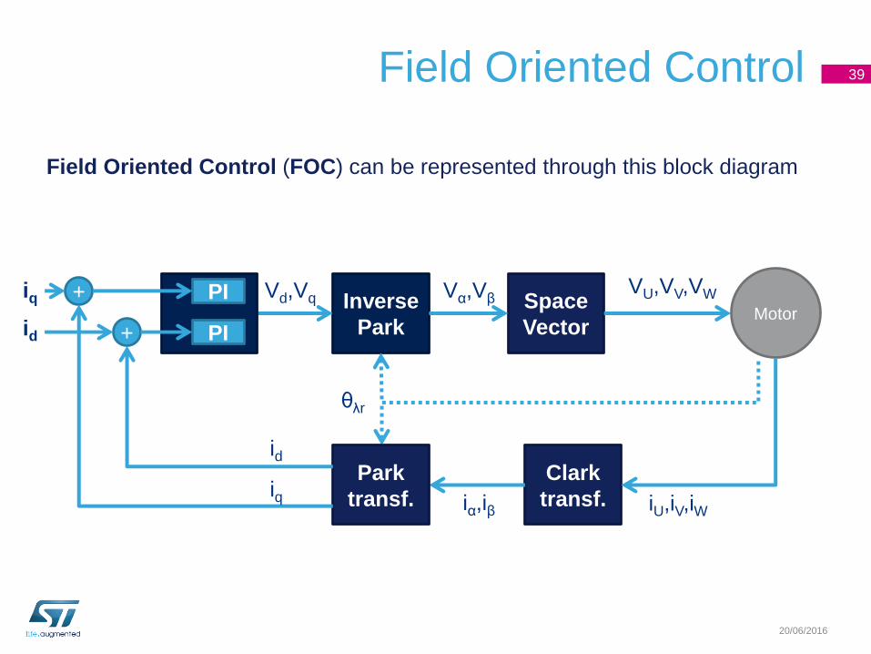
Field Oriented Control (FOC) can be represented through this block diagram
Inverse
Park
Space
Vector
Clark
transf.
Motor
PI
PI
+
+
Park
transf.
θλr
VU,VV,VWVα,VβVd,Vq
iU,iV,iWiα,iβ
id
iq
id
iq
Field Oriented Control 40
20/06/2016
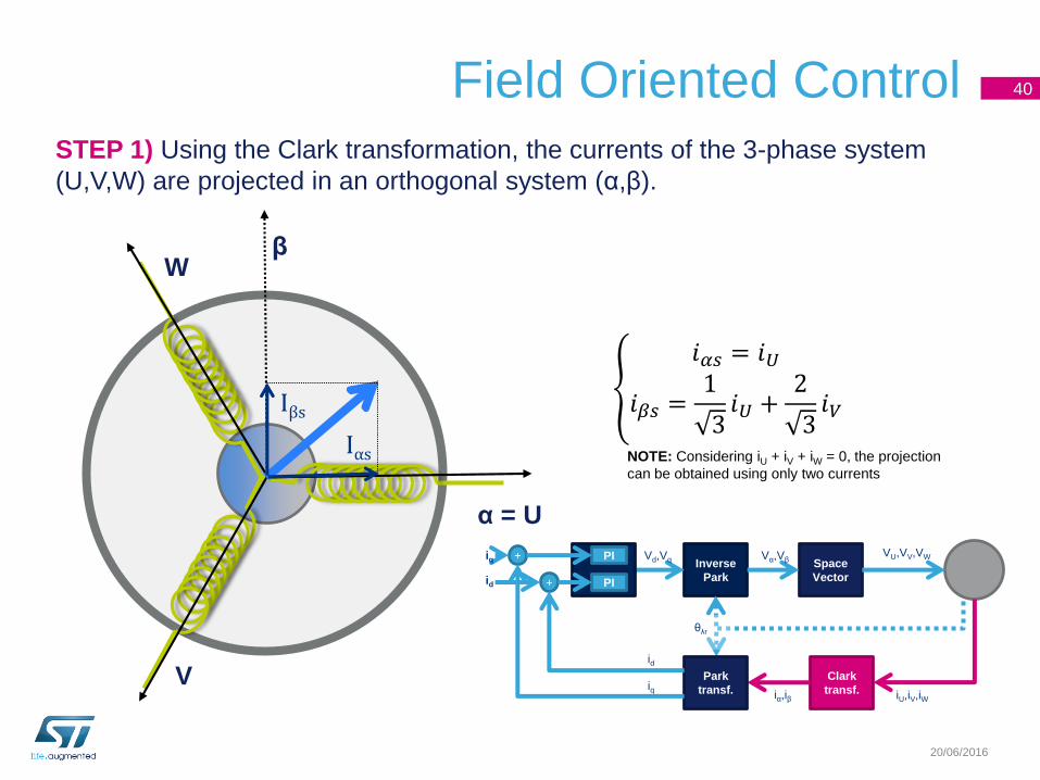
STEP 1) Using the Clark transformation, the currents of the 3-phase system
(U,V,W) are projected in an orthogonal system (α,β).
α = U
V
Wβ
Iαs
Iβs
𝑖𝛼𝑠 = 𝑖𝑈
𝑖𝛽𝑠 =1
3𝑖𝑈 +
2
3𝑖𝑉
NOTE: Considering iU + iV + iW = 0, the projection
can be obtained using only two currents
Inverse
Park
Space
Vector
Clark
transf.
PI
PI
+
+
Park
transf.
θλr
VU,VV,VWVα,VβVd,Vq
iU,iV,iWiα,iβ
id
iq
id
iq
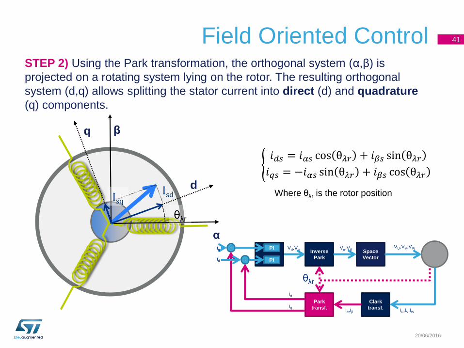
Field Oriented Control 41
20/06/2016
STEP 2) Using the Park transformation, the orthogonal system (α,β) is
projected on a rotating system lying on the rotor. The resulting orthogonal
system (d,q) allows splitting the stator current into direct (d) and quadrature
(q) components.
α
β
IsdIsq
q
d
θλr
𝑖𝑑𝑠 = 𝑖𝛼𝑠 cos θ𝜆𝑟 + 𝑖𝛽𝑠 sin θ𝜆𝑟𝑖𝑞𝑠 = −𝑖𝛼𝑠 sin θ𝜆𝑟 + 𝑖𝛽𝑠 cos θ𝜆𝑟
Where θλr is the rotor position
Inverse
Park
Space
Vector
Clark
transf.
PI
PI
+
+
Park
transf.
θλr
VU,VV,VWVα,VβVd,Vq
iU,iV,iWiα,iβ
id
iq
id
iq
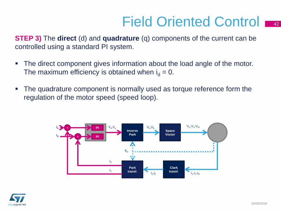
Field Oriented Control 42
20/06/2016
STEP 3) The direct (d) and quadrature (q) components of the current can be
controlled using a standard PI system.
The direct component gives information about the load angle of the motor.
The maximum efficiency is obtained when id = 0.
The quadrature component is normally used as torque reference form the
regulation of the motor speed (speed loop).
Vd,Vq
Inverse
Park
Space
Vector
Clark
transf.
PI
PI
+
+
Park
transf.
θλr
VU,VV,VWVα,Vβ
iU,iV,iWiα,iβ
id
iq
id
iq
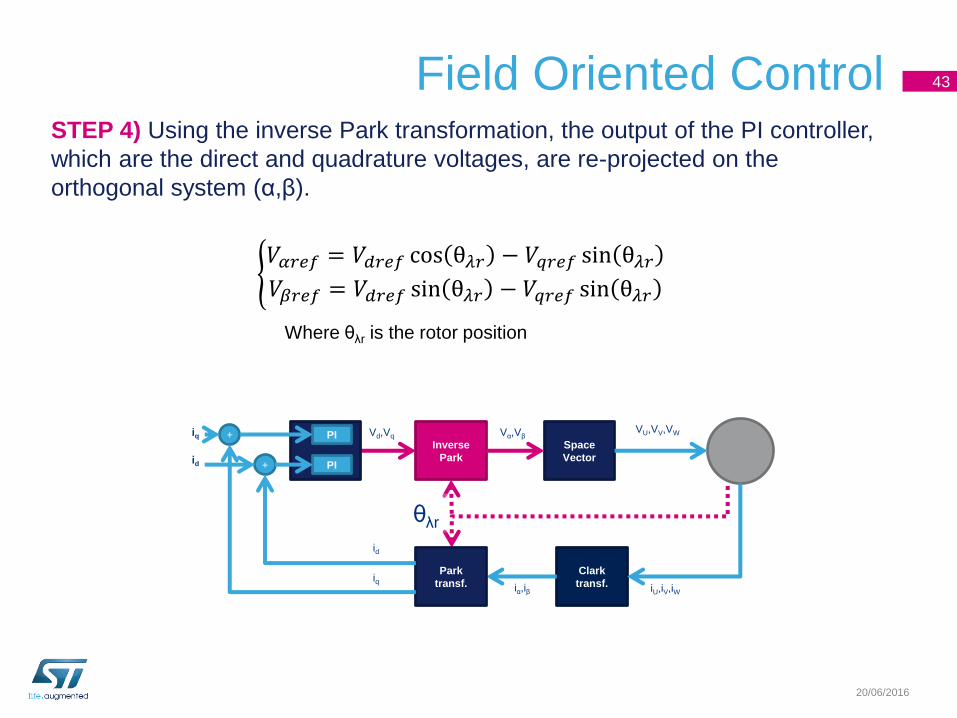
Field Oriented Control 43
20/06/2016
STEP 4) Using the inverse Park transformation, the output of the PI controller,
which are the direct and quadrature voltages, are re-projected on the
orthogonal system (α,β).
𝑉𝛼𝑟𝑒𝑓 = 𝑉𝑑𝑟𝑒𝑓 cos θ𝜆𝑟 − 𝑉𝑞𝑟𝑒𝑓 sin θ𝜆𝑟𝑉𝛽𝑟𝑒𝑓 = 𝑉𝑑𝑟𝑒𝑓 sin θ𝜆𝑟 − 𝑉𝑞𝑟𝑒𝑓 sin θ𝜆𝑟
Where θλr is the rotor position
Vd,Vq Vα,Vβ
Inverse
Park
Space
Vector
Clark
transf.
PI
PI
+
+
Park
transf.
θλr
VU,VV,VW
iU,iV,iWiα,iβ
id
iq
id
iq
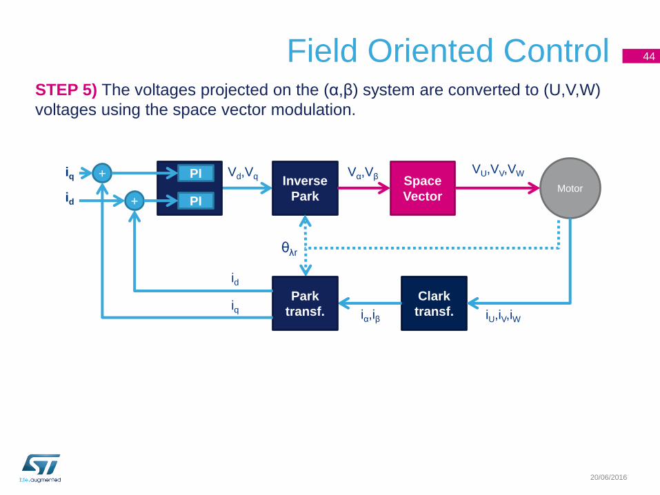
Field Oriented Control 44
20/06/2016
STEP 5) The voltages projected on the (α,β) system are converted to (U,V,W)
voltages using the space vector modulation.
VU,VV,VWVd,Vq Vα,VβInverse
Park
Space
Vector
Clark
transf.
Motor
PI
PI
+
+
Park
transf.
θλr
iU,iV,iWiα,iβ
id
iq
id
iq
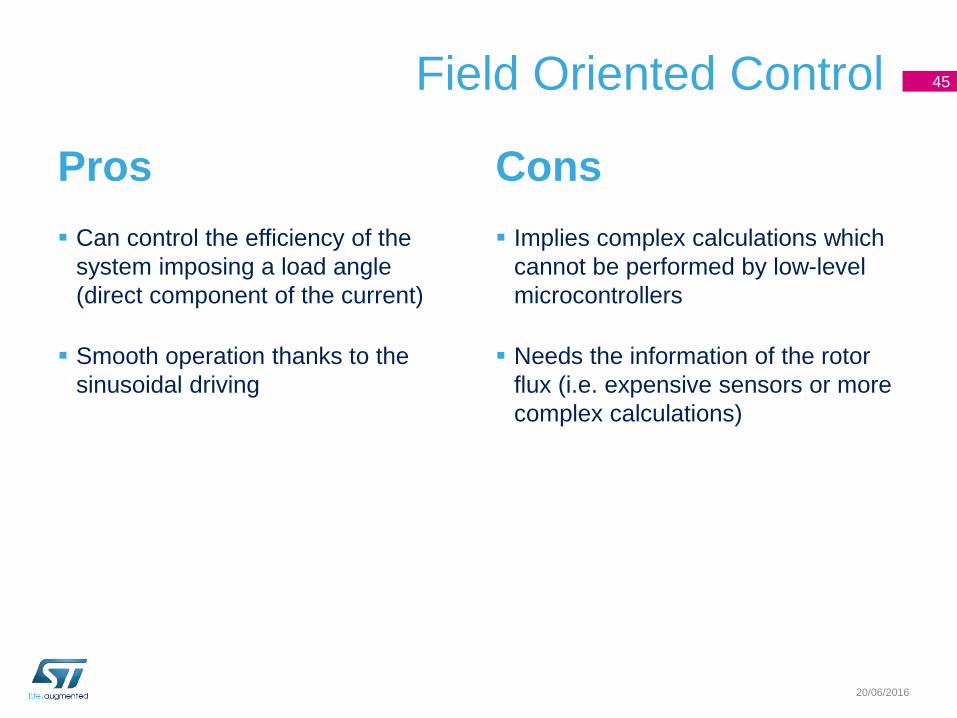
Field Oriented Control
Pros
Can control the efficiency of the
system imposing a load angle
(direct component of the current)
Smooth operation thanks to the
sinusoidal driving
45
20/06/2016
Cons
Implies complex calculations which
cannot be performed by low-level
microcontrollers
Needs the information of the rotor
flux (i.e. expensive sensors or more
complex calculations)
Three-phase brushless motor summary
• The stator magnetic field is the combination of the magnetic fields
generated by the motor phases.
• The magnetic field rotation is obtained driving in the proper way the
phases.
• The position of the rotor must be sensed in order to determine the
proper driving sequence.
46
20/06/2016

Bipolar stepper motor
20/06/2016
Stepper motors overview
There are different types of stepper motors:
• Unipolar (two phases)
• Bipolar (two phases)
• Three-phase
• Five-phase
The presentation will describe the basics of the bipolar stepper motor
because it is one of the most common versions.
In most cases, the considerations can be extended to the other types.
20/06/2016
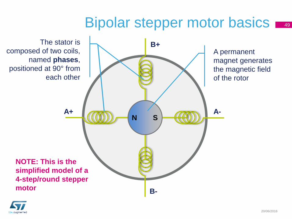
Bipolar stepper motor basics 49
20/06/2016
SNA+ A-
B+
B-
A permanent
magnet generates
the magnetic field
of the rotor
The stator is
composed of two coils,
named phases,
positioned at 90° from
each other
NOTE: This is the
simplified model of a
4-step/round stepper
motor
Bipolar stepper motor basics
The stepper motors are designed to keep a target angular position.
This objective is obtained by splitting the rotation of the shaft in small
fractions named steps.
Each step represents a stable position where the motor shaft can be
easily kept forcing the proper current into the phases.
50
20/06/2016
Bipolar stepper motor basics 51
20/06/2016
SNA+ A-
B+
B-
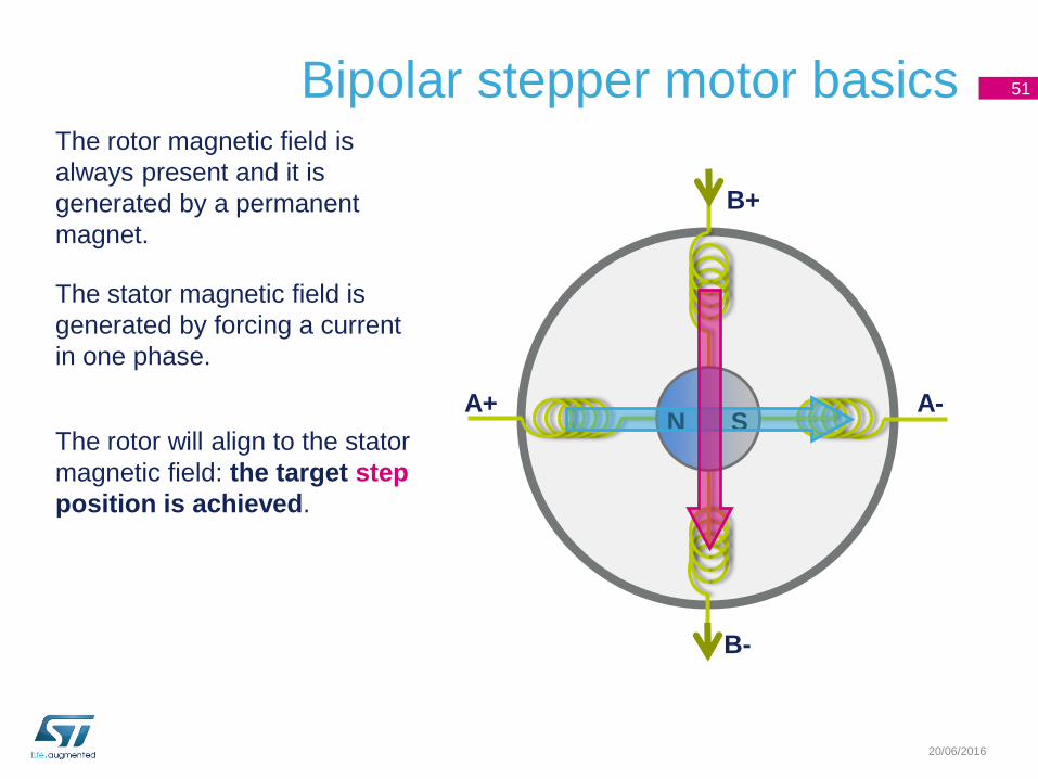
The rotor magnetic field is
always present and it is
generated by a permanent
magnet.
The stator magnetic field is
generated by forcing a current
in one phase.
The rotor will align to the stator
magnetic field: the target step
position is achieved.
Bipolar stepper motor basics
The phases have always to be driven following the proper sequence,
otherwise motor rotation cannot be achieved.
The stepper motor is moved by performing a series of small rotations,
i.e. steps. This way the mechanical position of the shaft is always
known without the need for a dedicated position sensor (*).
The motor speed is determined by the frequency at which the
sequence is performed and it is expressed in steps per second or
pulses per second (pps).
52
20/06/2016
(*) This is true only if the starting position is already known
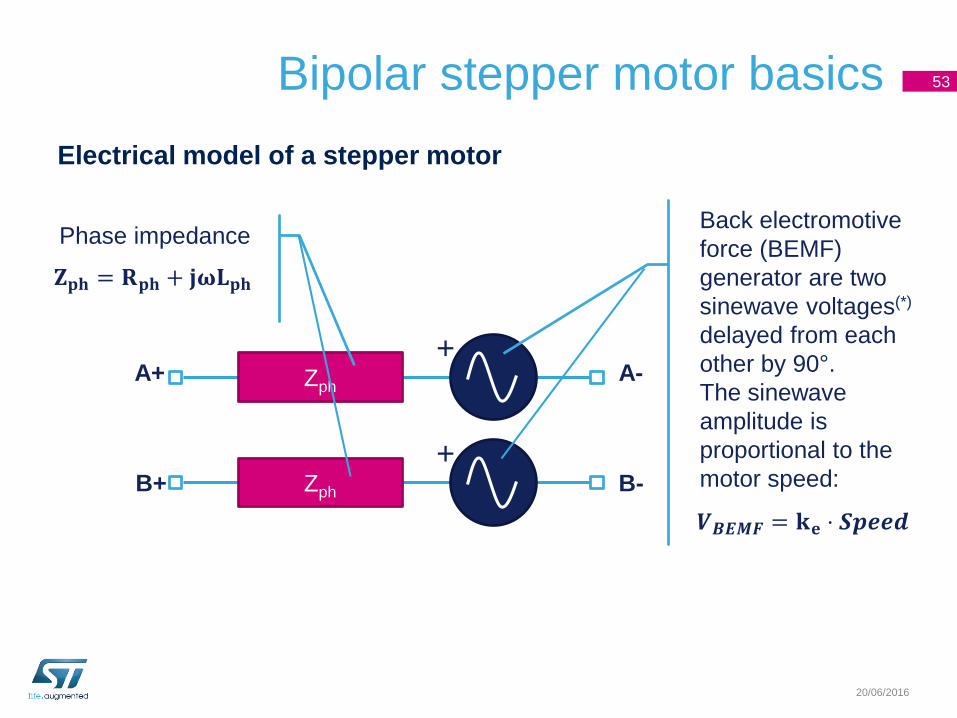
Bipolar stepper motor basics
Electrical model of a stepper motor
53
20/06/2016
Zph
+
Zph
+
Back electromotive
force (BEMF)
generator are two
sinewave voltages(*)
delayed from each
other by 90°.
The sinewave
amplitude is
proportional to the
motor speed:
Phase impedance
𝐙𝐩𝐡 = 𝐑𝐩𝐡 + 𝐣𝛚𝐋𝐩𝐡
𝑽𝑩𝑬𝑴𝑭 = 𝐤𝐞 ⋅ 𝑺𝒑𝒆𝒆𝒅
A+
B+ B-
A-
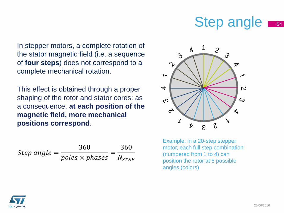
Step angle
In stepper motors, a complete rotation of
the stator magnetic field (i.e. a sequence
of four steps) does not correspond to a
complete mechanical rotation.
This effect is obtained through a proper
shaping of the rotor and stator cores: as
a consequence, at each position of the
magnetic field, more mechanical
positions correspond.
54
20/06/2016
12
3
4
Example: in a 20-step stepper
motor, each full step combination
(numbered from 1 to 4) can
position the rotor at 5 possible
angles (colors)
𝑆𝑡𝑒𝑝 𝑎𝑛𝑔𝑙𝑒 =360
𝑝𝑜𝑙𝑒𝑠 × 𝑝ℎ𝑎𝑠𝑒𝑠=
360
𝑁𝑆𝑇𝐸𝑃

Full step 55
20/06/2016
SN
A+ A-
B+
B-
Forcing the phase currents according to the following sequence, the motor rotates
performing one step at a time.
This is named Full-step 1 phase on driving or Full-step wave mode.
SN
A+ A-
B+
B-
S NA+ A-
B+
B-
SN
A+ A-
B+
B-
1 2 3 4
IphA = + IphA = 0 IphA = - IphA = 0
IphB = 0 IphB = + IphB = 0 IphB = -
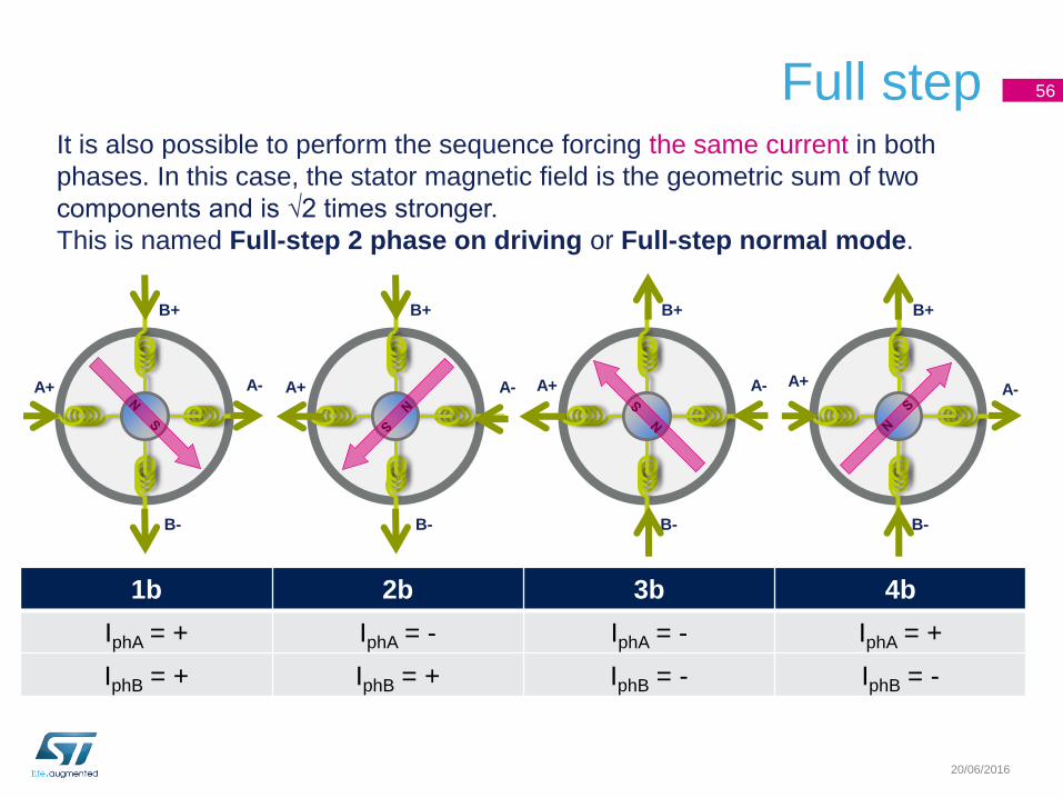
Full step 56
20/06/2016
A+ A-
B+
B-
It is also possible to perform the sequence forcing the same current in both
phases. In this case, the stator magnetic field is the geometric sum of two
components and is √2 times stronger.
This is named Full-step 2 phase on driving or Full-step normal mode.
A+ A-
B+
B-
A+ A-
B+
B-
A+A-
B+
B-
1b 2b 3b 4b
IphA = + IphA = - IphA = - IphA = +
IphB = + IphB = + IphB = - IphB = -
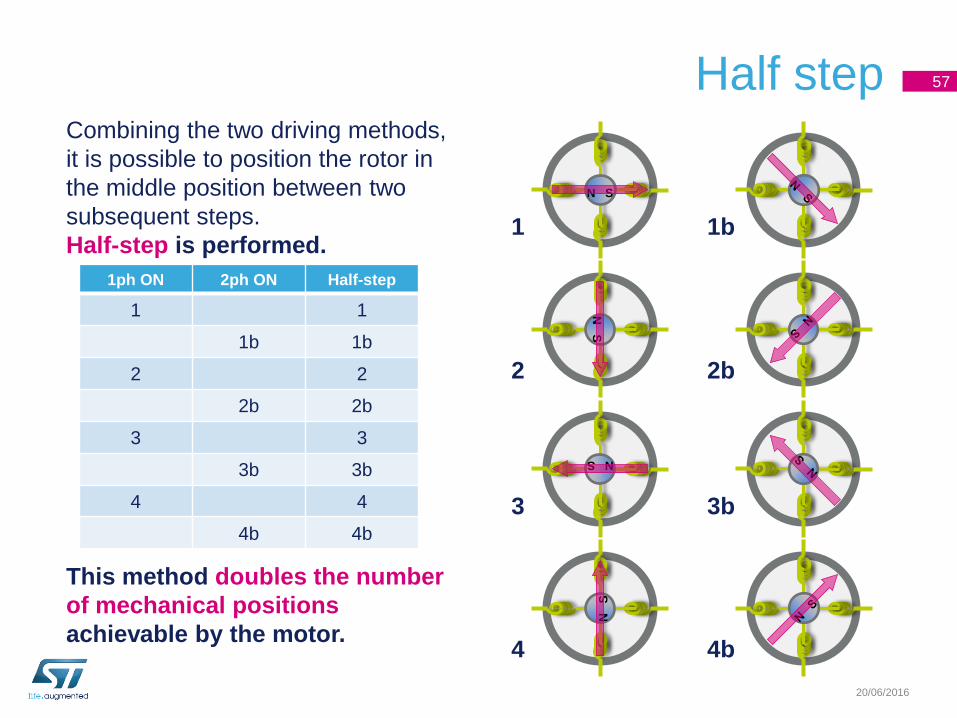
Half step 57
20/06/2016
SN
SN
S N
SN
1 1b
2 2b
3 3b
4 4b
1ph ON 2ph ON Half-step
1 1
1b 1b
2 2
2b 2b
3 3
3b 3b
4 4
4b 4b
Combining the two driving methods,
it is possible to position the rotor in
the middle position between two
subsequent steps.
Half-step is performed.
This method doubles the number
of mechanical positions
achievable by the motor.
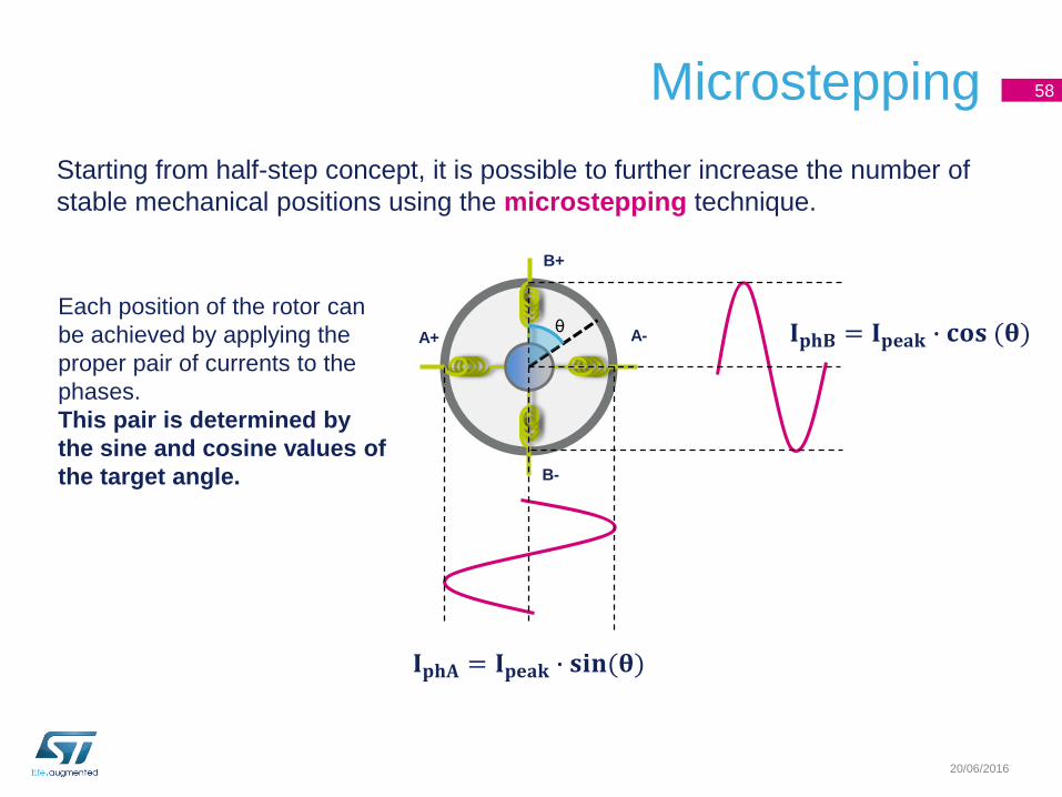
Microstepping 58
20/06/2016
Starting from half-step concept, it is possible to further increase the number of
stable mechanical positions using the microstepping technique.
Each position of the rotor can
be achieved by applying the
proper pair of currents to the
phases.
This pair is determined by
the sine and cosine values of
the target angle.
A+ A-
B+
B-
θ
𝐈𝐩𝐡𝐀 = 𝐈𝐩𝐞𝐚𝐤 ∙ 𝐬𝐢𝐧(𝛉)
𝐈𝐩𝐡𝐁 = 𝐈𝐩𝐞𝐚𝐤 ∙ 𝐜𝐨𝐬 (𝛉)
Microstepping 59
20/06/2016
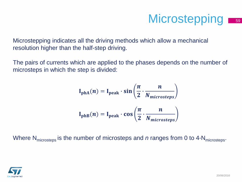
Microstepping indicates all the driving methods which allow a mechanical
resolution higher than the half-step driving.
The pairs of currents which are applied to the phases depends on the number of
microsteps in which the step is divided:
𝐈𝐩𝐡𝐀(𝒏) = 𝐈𝐩𝐞𝐚𝐤 ∙ 𝐬𝐢𝐧𝝅
𝟐∙
𝒏
𝑵𝒎𝒊𝒄𝒓𝒐𝒔𝒕𝒆𝒑𝒔
𝐈𝐩𝐡𝐁(𝒏) = 𝐈𝐩𝐞𝐚𝐤 ∙ 𝐜𝐨𝐬𝝅
𝟐∙
𝒏
𝑵𝒎𝒊𝒄𝒓𝒐𝒔𝒕𝒆𝒑𝒔
Where Nmicrosteps is the number of microsteps and n ranges from 0 to 4∙Nmicrosteps.
Microstepping
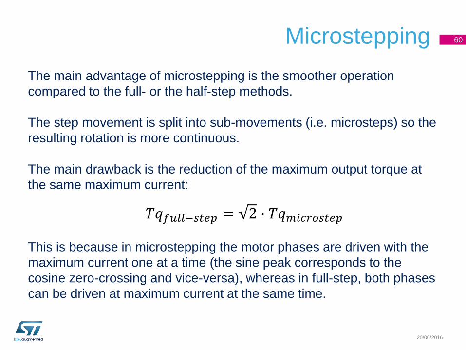
The main advantage of microstepping is the smoother operation
compared to the full- or the half-step methods.
The step movement is split into sub-movements (i.e. microsteps) so the
resulting rotation is more continuous.
The main drawback is the reduction of the maximum output torque at
the same maximum current:
This is because in microstepping the motor phases are driven with the
maximum current one at a time (the sine peak corresponds to the
cosine zero-crossing and vice-versa), whereas in full-step, both phases
can be driven at maximum current at the same time.
60
20/06/2016
𝑇𝑞𝑓𝑢𝑙𝑙−𝑠𝑡𝑒𝑝 = 2 ∙ 𝑇𝑞𝑚𝑖𝑐𝑟𝑜𝑠𝑡𝑒𝑝
Torque vs Angle characteristic 61
20/06/2016
Displacement
Torque
θSTEP
4 x θSTEP
Unstable region
θL
TqMAX
TqLOAD
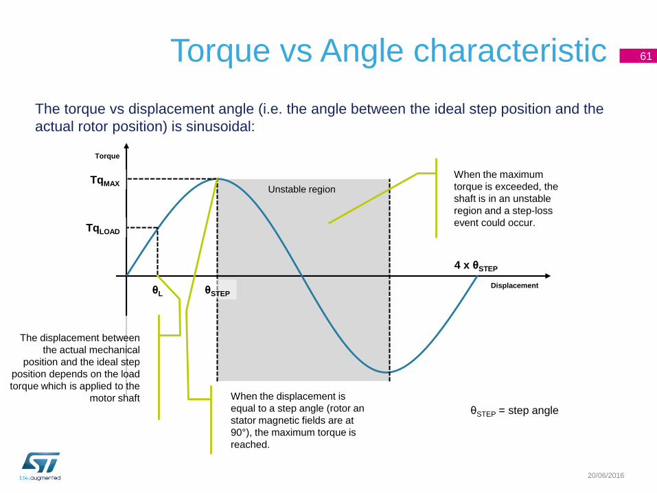
The displacement between
the actual mechanical
position and the ideal step
position depends on the load
torque which is applied to the
motor shaft
The torque vs displacement angle (i.e. the angle between the ideal step position and the
actual rotor position) is sinusoidal:
When the maximum
torque is exceeded, the
shaft is in an unstable
region and a step-loss
event could occur.
When the displacement is
equal to a step angle (rotor an
stator magnetic fields are at
90°), the maximum torque is
reached.
θSTEP = step angle
Torque vs Angle characteristic 62
20/06/2016
Displacement
Torque
4 x θSTEP
Unstable region
θL
TqMAX
TqLOAD
θSTEP = step angle
θL+θSTEP
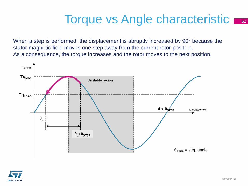
When a step is performed, the displacement is abruptly increased by 90° because the
stator magnetic field moves one step away from the current rotor position.
As a consequence, the torque increases and the rotor moves to the next position.
Torque vs Angle characteristic 63
20/06/2016
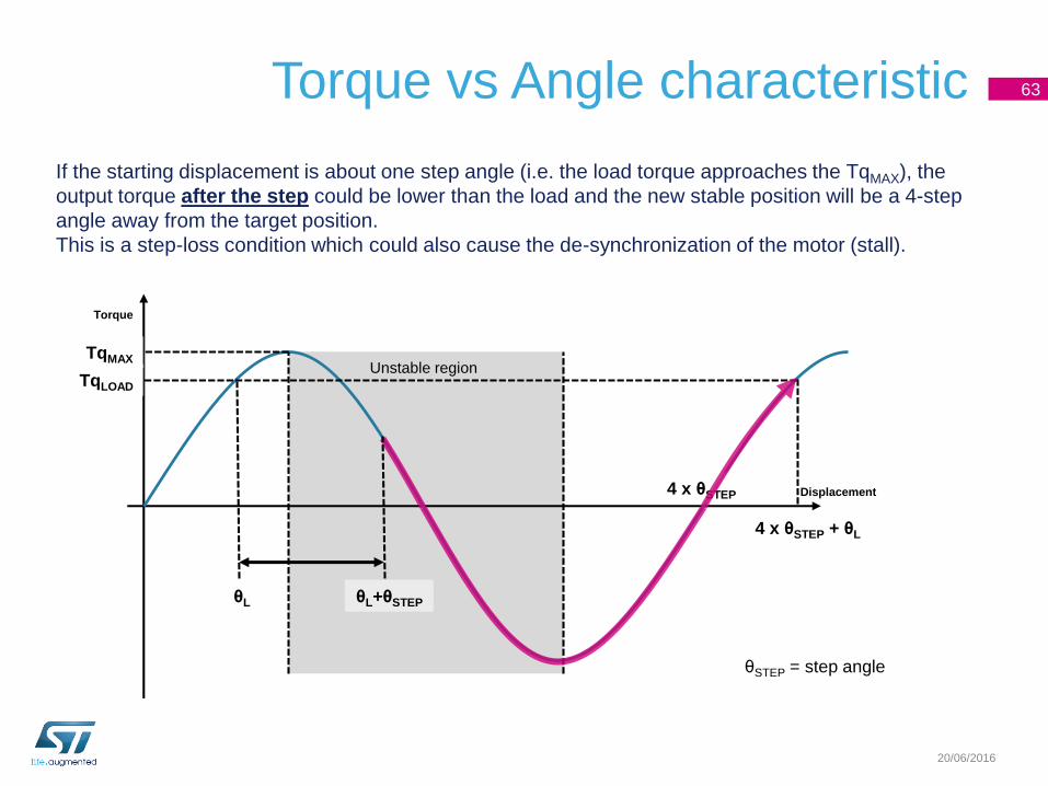
If the starting displacement is about one step angle (i.e. the load torque approaches the TqMAX), the
output torque after the step could be lower than the load and the new stable position will be a 4-step
angle away from the target position.
This is a step-loss condition which could also cause the de-synchronization of the motor (stall).
Displacement
Torque
4 x θSTEP
Unstable region
θL
TqMAX
TqLOAD
θSTEP = step angle
4 x θSTEP + θL
θL+θSTEP
Stall and step-loss
When the stepper motor is loaded with a torque exceeding its torque
vs. speed characteristic, a stall or a step-loss event could occur.
The stepper motor is in stall when it completely loses the synchronism.
As result, the rotor is stopped or vibrates, but no rotation is performed.
When a step-loss occurs, the motor loses the synchronism for a short
period and then resumes.
As result, the rotor continues its rotation, but the actual position is
different from the ideal one.
64
20/06/2016
Speed
Torque
Start-Stop region
Slew region
Max
speed
Max starting
speed
Holding
torquePull-out curve
Pull-in curve
Torque vs. Speed characteristic 65
20/06/2016
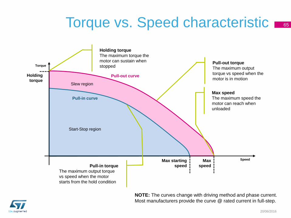
Pull-out torque
The maximum output
torque vs speed when the
motor is in motion
Max speed
The maximum speed the
motor can reach when
unloaded
Pull-in torque
The maximum output torque
vs speed when the motor
starts from the hold condition
Holding torque
The maximum torque the
motor can sustain when
stopped
NOTE: The curves change with driving method and phase current.
Most manufacturers provide the curve @ rated current in full-step.
Resonances 66
20/06/2016
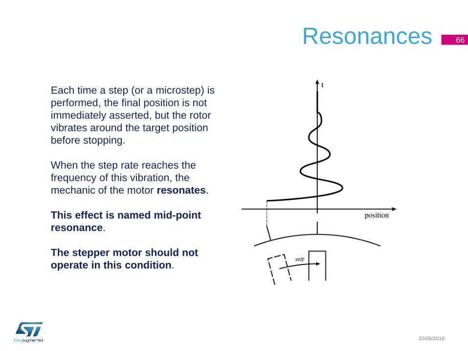
Each time a step (or a microstep) is
performed, the final position is not
immediately asserted, but the rotor
vibrates around the target position
before stopping.
When the step rate reaches the
frequency of this vibration, the
mechanic of the motor resonates.
This effect is named mid-point
resonance.
The stepper motor should not
operate in this condition.
Resonances
Effects of the resonances:
• Strong vibrations: the motor is very noisy because the resonances
stimulate the internal mechanic.
• Reduced torque: the energy is “dissipated” by the resonance
(vibrations) so a minor par of the energy is converted into an effective
torque.
• Discontinuous motion: if vibration are strong enough to move the
rotor in the unstable region, step-loss events could occurs.
67
20/06/2016
Bipolar stepper motor summary
• The stepper motor is designed to move the rotor in a target position
and keep it.
• The stator magnetic field is the combination of the magnetic fields
generated by the motor phases.
• Each combination of currents in the motor phases moves and keeps
the motor in a stable position. At each position of the magnetic field,
more mechanical positions may correspond.
• The motor rotation is performed through a proper sequence of phase
currents.
• The rotation is always performed one step (or microstep) at a time.
68
20/06/2016
Further information and full design support can be found at www.st.com/stspin