Embed Size (px)
Citation preview

An Introduction to Constructing and Maintaining Cathodic Protection Systems Course No: T02-009
Credit: 2 PDH
J. Paul Guyer, P.E., R.A., Fellow ASCE, Fellow AEI
Continuing Education and Development, Inc.22 Stonewall CourtWoodcliff Lake, NJ 07677
P: (877) [email protected]
© J. Paul Guyer 2015 1
J. Paul Guyer, P.E., R.A. Editor Paul Guyer is a registered civil engineer, mechanical engineer, fire protection engineer, and architect with over 35 years of experience in the design of buildings and related infrastructure. For an additional 9 years he was a principal advisor to the California Legislature on infrastructure and capital outlay issues. He is a graduate of Stanford University and has held numerous national, state and local offices with the American Society of Civil Engineers, Architectural Engineering Institute and National Society of Professional Engineers. He is a Fellow of ASCE and AEI.
An Introduction to Constructing and Maintaining Cathodic Protection Systems

© J. Paul Guyer 2015 2
CONTENTS
1. INSTALLATION AND CONSTRUCTION PRACTICES 2. SYSTEM CHECKOUT AND INITIAL ADJUSTMENTS 3. MAINTAINING CATHODIC PROTECTION SYSTEMS
(This publication is adapted from the Unified Facilities Criteria of the United States government which are in the public domain, have been authorized for unlimited distribution, and are not copyrighted.)

© J. Paul Guyer 2015 3
1. INSTALLATION AND CONSTRUCTION PRACTICES
1.1 FACTORS TO CONSIDER. Cathodic protection systems, and the structure to be
protected, must be properly installed in order for effective protection to be achieved.
NACE Standards RP-02 and RP-01 include guidelines for installation of such systems.
Particular attention should be paid to maintaining the condition of the coating on the
structure and maintaining the structural continuity and isolation required for proper
cathodic protection system operation. If the coating on a structure is damaged (or absent),
cathodic protection requirements will increase dramatically. A well-coated structure will
often require only 1 percent or less of the current required to protect the same structure
if bare. Sacrificial anode systems, which cannot be easily adjusted to provide increased
current output, are the most susceptible to poor performance if the coating system does
not meet original specifications. Open bonds and shorts to other structures are common
causes of inadequate protection and the resulting interference can cause accelerated
corrosion damage. Careful inspection during the entire construction process, both of the
cathodic protection system and of the structures to be protected are vital to the successful
application of cathodic protection.
1.2 PLANNING OF CONSTRUCTION. The most important factor in the planning of
construction of facilities that include cathodic protection is the planning of inspections to
insure that coatings are properly applied and not damaged during construction, and that
proper isolation and bonding are achieved. For buried structures, these inspections must
be performed before backfilling. Once the structure or other system components are
buried, identification and correction of any discrepancies is difficult.
1.3 PIPELINE COATING. Interference problems are severe for long structures such as
pipelines. It is highly desirable to reduce the amount of current required to protect
pipelines to the lowest levels possible. High quality coatings, properly selected and
applied, and installation of the line without damaging the coating is vital to achieving
protection at the low current levels desired. Often, coating application and prevention of
damage during installation are more important than the materials used.

© J. Paul Guyer 2015 4
1.3.1 OVER-THE-DITCH COATING. Over-the-ditch coating systems have the advantage
of reducing handling of the coated pipe before installation. Over-the-ditch coating is best
used when long sections of pipeline are to be installed in open areas under mild weather
conditions. Depending on curing time for the coating, the pipe may either be lowered
directly into the ditch after coating or may be held on skids until the coating is properly
cured before lowering it into the ditch. If the pipe is lowered into the ditch directly after
coating, the inspector should electrically inspect each section using a holiday detector or
"jeep" immediately before backfilling. If the pipeline is held on skids, the skids should be
padded to prevent coating damage. Damage caused by skids must be patched before
inspection of the coating, lowering of pipeline into the ditch, and backfilling.
1.3.2 YARD APPLIED COATING. The use of yard or mill applied coatings is preferred
over field applied coatings since better surface preparation and application are normally
achieved under the more controlled conditions at a stationary plant. The coating should
be inspected upon receipt at the construction site when unloading. Inspections should be
performed immediately prior to placing the pipe in the ditch after all joint and field patches
have been made.
1.3.3 JOINT AND DAMAGE REPAIR. Joints and field repairs should be made with
coatings compatible with the primary coating system used. Joints and field patches should
be carefully inspected before placing the pipe in the ditch.
1.3.4 INSPECTION. Electric Holiday Detectors should be used for all coating inspections.
If properly used they can detect flaws in the coating which may not be visible. In addition
to the use of the Holiday Detector, the inspector should also make detailed visual
inspection of the coatings and occasional measurements of the bond strength. Visual
inspection should also include observation of the following:
a) surface preparation and coating - if practical
b) handling of the pipe
c) lowering of the pipe into the ditch

© J. Paul Guyer 2015 5
d) backfilling operations
Any material, even the highest quality, when applied and handled carelessly will perform
poorly, but a marginal quality material will perform well when carefully applied and
installed.
1.4 COATINGS FOR OTHER STRUCTURES. Coatings on other structures are equally
critical when the cathodic protection system relies on the quality of the coating to achieve
protective potentials with the available system current. Inspections during surface
preparation, coating, handling, placement, and backfilling are vital to the performance of
the overall system.
1.5 PIPELINE INSTALLATION. The use of casings to give mechanical protection to the
pipeline at grade crossings, etc., is sometimes required by law, code, or physical
condition. The use of casings should be avoided wherever possible due to the difficulty
of protecting the pipeline within the casing and difficulties in maintaining isolation between
the casing and the pipeline. The use of proper techniques when foreign pipeline crossings
are made is necessary to minimize interference. Insulating joints should be properly
installed. Effectiveness is achieved using adequate test and bonding stations.
1.5.1 CASINGS. Casings should be uncoated. The casing should be isolated from the
pipeline with insulators and cradles which must be properly installed. The annular space
at the ends of the casing should be sealed to prevent the entry of moisture between the
casing and pipe. Extra thickness of coating on the pipeline for the section to be placed
inside the casing may be required in order to prevent damage to the coating when the
pipe is pulled into the casing. The annular space between the casing and the pipe must
be kept dry until it is sealed. Casing-to-pipe resistance should be measured. A test station
should be installed at the casing for future measurements. Figure 1 shows a test station
for casing isolation testing.
1.5.2 FOREIGN PIPELINE CROSSINGS. Newly installed pipelines are common installed
under existing lines. The owner of the foreign line should be contacted to obtain

© J. Paul Guyer 2015 6
permission to install test leads and possibly to coat short section of the foreign line. Since
solutions to problems at foreign crossings require cooperative efforts, effective
coordination is essential. Clearance of 2 feet between all lines at crossings is
recommended. If 1-foot clearance cannot be obtained, the use of an insulating mat as is
required. Direct contact between lines should be avoided at almost any cost. Installation
of insulating mat crossings is recommended if substantial earth currents are detected in
the area or if a new coated line is crossing a poorly coated or uncoated line. Installation
of test stations with provisions for bonding at all crossings is essential.
Figure 1
Test station for under-road casing isolation
1.5.3 INSULATING JOINTS. Insulating, or isolating joints must be selected so that the
materials are compatible with the service environment. Isolation of steam conduits is
especially troublesome. Isolating couplings must be properly assembled and tested to
insure that they will be effective. When used on welded pipelines, short "spools" of pipe
should be welded to each flange. The flange should then be assembled and the section
welded into the pipeline. This will prevent mechanical damage to the insulating joint
associated with misalignment. Flanges should be tested with a radio frequency type
insulation checker after assembly to insure that they have been properly assembled.
Effectiveness of buried flanges must be verified by impressing a potential on one side of
the flange and measuring the change in potential on the other side of the flange. If little

© J. Paul Guyer 2015 7
or no potential change is noted, the isolating flange is effective. Test stations with
provisions for future bonding should be installed at each buried insulating flange.
1.5.4 BONDS. Bonds between structure sections and to foreign structures should be
made with No. 4 AWG, 7-strand insulated cable unless larger cable is required. Each
bond should be brought into a test station to determine bond effectiveness and to install
resistive bonds if required.
1.6 ELECTRICAL CONNECTIONS. Electrical connections to the structure are commonly
made using thermo-weld techniques. The connections should be inspected visually
before and after insulation is applied. If safety or other conditions preclude the use of the
thermo-weld process on site, the leads should be attached to metal tabs by thermo-
welding and the tabs either soldered or mechanically attached to the structure. All
electrical connections should be insulated. Other electrical connections should be thermo-
welded where practical as this method of connection is extremely reliable. Mechanical
connections should be of the proper type for the intended use and should be properly
assembled. All connections should be inspected before and after insulation.
1.7 TEST STATIONS. Test stations are required for initial test and adjustment of the
cathodic protection systems, and for future inspection and maintenance. Attachment of
"spare" test leads to buried structures is recommended as excavation to reconnect test
leads is expensive. All test station leads should be either color coded or labeled with a
metal or plastic tag. The connections to the structure should be inspected prior to burial
of the structure. Whenever the structure will be located under a paved area, or whenever
paving is installed over a protected structure, soil contact test stations as shown in should
be installed.
1.8 SACRIFICIAL ANODE INSTALLATION. Sacrificial anodes should always be
installed at least 3 feet below grade whenever possible. The top of the anode should be
at least as deep as the structure to be protected. Horizontal sacrificial anode installations
should be used only if obstructions such as rock outcrops preclude vertical installations.

© J. Paul Guyer 2015 8
Anodes suspended in water should be installed according to the system design and a
cable connection between the structure and the suspension link is normally required.
Anode lead wires should never be used to suspend, carry, or install the anode.
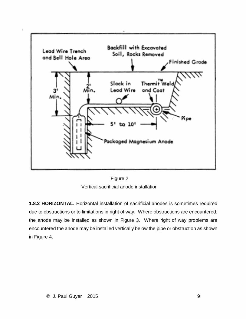
1.8.1 VERTICAL. Sacrificial anodes are commonly installed vertically in augered holes.
If caving or unstable soil conditions are encountered, a thin metal (stovepipe) casing may
be used. Anodes should be located on alternating sides of the pipe when possible to
reduce interference and allow for more even current distribution. Any impermeable
wrapping should be removed from packaged anodes prior to placing them in the holes.
The cloth bag used with packaged anodes should be carefully handled as loss of backfill
will result in reduced anode output. The anodes should be lowered into the holes either
by hand, or by the use of a line attached to either the anode, if bare, or the top of the bag
of backfill. The anode lead cable should not be used to lower the anode into the hole as
the anode-to-cable connection is easily damaged. Sufficient slack should be left in the
anode cable to prevent strain on the cable. All connections should be properly made and
inspected before the installation is buried. If packaged anodes are not used and special
backfill is required, it should be poured into the holes as the anodes are installed. Anode
holes should be backfilled with fine soil free of stones or other debris. Sand should not be
used. The backfill should be placed in 6-inch lifts and each lift tamped into place to
eliminate voids.
© J. Paul Guyer 2015 9
Figure 2
Vertical sacrificial anode installation
1.8.2 HORIZONTAL. Horizontal installation of sacrificial anodes is sometimes required
due to obstructions or to limitations in right of way. Where obstructions are encountered,
the anode may be installed as shown in Figure 3. Where right of way problems are
encountered the anode may be installed vertically below the pipe or obstruction as shown
in Figure 4.

© J. Paul Guyer 2015 10
1.9 IMPRESSED CURRENT ANODE INSTALLATION. Selection of sites for the
rectifiers, anode beds, test stations, and other components of an impressed current
cathodic protection system should be made during the system design. As in the case of
sacrificial anode systems, impressed current systems must be carefully installed in order
to operate properly and reliably. The most common type of impressed current anode
installation is vertical. Horizontal installations are sometimes used if obstructions are
encountered or if near surface soil resistivities are sufficiently low. Deep well anode
installations are used to reduce interference effects or to reach low resistivity soil. Anode
lead wires should never be used to suspend, carry, or install anode.
Figure 3
Horizontal sacrificial anode installation when obstruction is encountered

© J. Paul Guyer 2015 11
Figure 4
Horizontal sacrificial anode installation – limited right-of-way
1.9.1 VERTICAL. This is the most common type of impressed current anode installation.
Both graphite and HSCBCI anodes are brittle and must be carefully handled to prevent
breakage. The anode cable is particularly prone to failure if the insulation is damaged in
any way and particular care must be exercised in handling the anode leads. As impressed
current cathodic protection anodes are generally longer than sacrificial anodes,
excavation of holes for them is often more difficult. "Jetting" of bare anodes is sometimes
possible in sandy soils using equipment specially designed for this purpose.. If caving of
the hole is encountered, either the use of a packaged "canned" anode complete with
backfill, or a thin metal "stovepipe" casing may be necessary. If bare anodes are used,
the backfill should be added as soon as the anodes are placed. The backfill should be
well tamped to insure good contact with the anode. The backfill should be used to fill the
hole to within a few inches of grade unless coarse gravel is available for this purpose.
This is to allow the gasses generated during system operation to be properly vented. A
typical vertical anode installation using a bare HSCBCI anode with backfill is shown in
Figure 5. A typical vertical installation of a "canned" HSCBCI anode is shown in Figure 6.
1.9.2 HORIZONTAL. Horizontal installations of impressed current anodes are less
expensive than vertical anodes. Horizontal installations may be necessary when

© J. Paul Guyer 2015 12
obstructions or other soil conditions make augering of deep holes difficult. Horizontal
installations are also used where soil resistivities are very low and the increased
resistance of the horizontal installation is not significant. A typical horizontal installation
of a HSCBCI anode is shown in Figure 7. A minimum of 2 feet of burial for all cables and
3 feet of burial for the anode is recommended. The excavation should be partially filled
with backfill before the anode is placed. After the anode is placed, the remainder of the
backfill should be added and tamped into place. If backfill is not required, soil free from
stones or debris should be used to fill the excavation. Again, it must be remembered that
impressed current anodes, and particularly the anode leads, are susceptible to damage
and must be handled carefully.
1.9.3 DEEP ANODE BEDS. In some installations where interference problems are
severe, anode beds are sometimes installed deep below the surface. This causes the
current flow to become more vertical and reduces interference between horizontally
displaced structures. Deep anodes are also used where the resistivity of the soil near the
surface is high. Anodes installed deeper than 50 feet are called "deep" anodes.
Specialized equipment and skill is required for the installation of such an anode array.
Installation of deep anode systems is described in NACE Standard RP-50-72. Type TAD
HSCBCI or center tapped 3- by 60-inch graphite are suitable for such installations. Newly
developed deep anode systems using platinized anodes show considerable promise for
such applications. A typical deep anode system using HSCBCI anodes is shown in
Figures 8 and 9.

© J. Paul Guyer 2015 13
Figure 5
Vertical HSCBCI anode installation

© J. Paul Guyer 2015 14
Figure 6
Vertical HSCBCI anode installation with packaged backfill

© J. Paul Guyer 2015 15
Figure 7
Horizontal HSCBCI anode installation

© J. Paul Guyer 2015 16
Figure 8
Typical deep well anode cathodic protection installation

© J. Paul Guyer 2015 17
Figure 9
Deep anode installation details

© J. Paul Guyer 2015 18
1.9.4 OTHER ANODE TYPES. Button anodes and platinized anodes are commonly
mounted directly on the structure. Their installation requires that the anode element be
electrically isolated from the structure so that the protective current will flow through the
electrolyte. Maintaining this isolation requires that the anodes be mounted in accordance
with the manufacturer's instructions for the specific type and size of anode being used. In
addition, a high quality protection coating or plastic shield is often required in the vicinity
of a flush-mounted anode in order to insure proper current distribution. Anodes
suspended in water should never be suspended using the cable leads but should be
suspended using either chemical resistant lines or net bags. Nylon and polypropylene are
commonly used for such applications.
1.9.5 CONNECTIONS. All connections between the anodes and rectifier in impressed
current cathodic protection systems are extremely critical. The number and location of all
connections and splices should be kept to a minimum and should be installed according
to the design and not left to the discretion of the installer. Thermo-weld connections are
preferred, although mechanical connections may be used. All of the connections in
contact with the electrolyte should be encapsulated using epoxy material.
1.10 IMPRESSED CURRENT RECTIFIER INSTALLATION. Rectifiers are usually either
pole-mounted or pad-mounted units. They should be installed according to applicable
codes and guidance applicable to all electrical. Even though exposed wiring may be
permissible, wiring in conduit is preferred to reduce vandalism and deterioration. All
rectifier installations should be equipped with a fused switch to allow disconnection of
power to the rectifier. Typical pole mounted and pad mounted rectifier installations are
shown in Figures 10 and 11.

© J. Paul Guyer 2015 19
Figure 10
Typical pole mounted cathodic protection rectifier installation

© J. Paul Guyer 2015 20
Figure 11
Typical pad-mounted cathodic protection rectifier installation

© J. Paul Guyer 2015 21
2. SYSTEM CHECKOUT AND INITIAL ADJUSTMENTS
2.1 INTRODUCTION. After a cathodic protection system is installed, it must be checked
out to determine if protective potentials have been achieved without interference to other
structures in the vicinity. Initial testing should be considered to be part of the system
design and installation and should be the responsibility of the designer of the system. The
structure-to-electrolyte potential measurement is the basic measurement that is used to
determine if proper levels of protection have been achieved. The -850 mV or 100 mV
negative polarization shift criteria are recommended for evaluation of the effectiveness of
cathodic protection systems on steel structures. Problems with interference can be
identified during the initial system checkout and should be corrected as soon as possible
to prevent premature failure.
2.2 INITIAL POTENTIAL SURVEY. Structure-to-electrolyte potentials should be
measured at each test station or test point. Due to polarization effects, these potentials
may change substantially within the first year of installation, and should be checked
monthly for the first 3 months, then quarterly for the remainder of the first year. Low
potential readings may be due to inadequate protective current flow, coating damage, or
interference. Sacrificial anode output currents should be measured at each potential
current test station since anode current measurements can be used to determine the
cause of low potential readings and to better estimate sacrificial anode consumption
rates. Anode currents should also be read monthly for the first 3 months and then
quarterly for the duration of the first year.
2.3 DETECTION AND CORRECTION OF INTERFERENCE. Interference is normally
detected by analysis of structure-to-electrolyte potentials made during initial system
checkout. Unusually high or low potential readings are found over points where current is
either entering or leaving the structure.
2.4 ADJUSTMENT OF IMPRESSED CURRENT SYSTEMS. Adjustment of rectifier
output is the most common adjustment made in impressed current cathodic protection

© J. Paul Guyer 2015 22
systems. Underprotection or overprotection can be corrected by adjusting rectifier output
if the structure-to-electrolyte potentials are fairly uniform over the structure and the
required output is within the capacity of the rectifier. Rectifier output should not require
frequent adjustment as system changes that can be corrected by rectifier adjustment
occur slowly. Improper system potentials may also be the result of unusual seasonal
conditions and may be self-correcting.
2.4.1 UNEVEN STRUCTURE-TO-ELECTROLYTE POTENTIALS. If the structure-to-
electrolyte potentials are vastly uneven, overprotection or underprotection in some areas
in order to achieve proper potentials in other areas may result. In this case, if interference
is not present, output of anodes at the areas of underprotection will have to be increased
or anodes added. The output of anodes in the areas of over protection will have to be
reduced. If the anodes are connected through resistors, resistor adjustment may be
adequate. If the structure is protected by impressed systems with point ground beds,
underprotected areas may have to be improved by the addition of impressed current
anode beds in appropriate locations. If the anodes are not connected through resistors,
resistors may be added. Protective output can be increased or decreased locally by
installing additional anodes or disconnecting anodes as necessary.
2.4.2 RECTIFIER VOLTAGE AND CURRENT CAPACITY. If the voltage capacity of the
rectifier is inadequate to provide sufficient current to achieve protection, reduction of
system resistance by the installation of additional anodes may be appropriate. If the
current capacity of the rectifier proves inadequate, and correction of any interference or
shorts does not result in adequate protection over a period of 1 year, then additional
current must be supplied either by installing an additional rectifier in parallel with the
existing rectifier, or installing a larger capacity rectifier in place of the existing rectifier.
2.5 ADJUSTMENT OF SACRIFICIAL ANODE SYSTEMS. Overprotection in sacrificial
anode cathodic protection systems is rare as the open circuit (maximum) potential of most
anode materials is normally less than that potential considered to be excessive. Potentials
more negative than those required for protection are, however, wasteful and will result in

© J. Paul Guyer 2015 23
premature anode consumption. Potentials in sacrificial anode cathodic protection
systems can be easily adjusted by inserting an adjustable resistor in the anode lead and
adjusting it to give the current required for adequate protection.
2.5.1 LOW ANODE CURRENT LEVELS. Low anode current output resulting in
inadequate protection is common in sacrificial anode cathodic protection systems. Low
anode current output can be the result of high soil resistivity or high circuit resistance. If
high soil resistivity is suspected, wet down the soil over the anodes and remeasure the
current output after a few days. If the current increases to give adequate protection, then
high soil resistivity problems have been confirmed. If lowering the soil resistivity in the
vicinity of the anodes does not result in increased anode output, then high circuit
resistance may be the problem and all leads and connections should be checked. If all
leads and connections are all right and the output is still too low, then more anodes are
required to provide additional current. In the case of an impressed system, the rectifier
voltage may be increased.
2.5.2 INADEQUATE PROTECTION AT DESIGNED CURRENT LEVELS. If a situation is
encountered where anode current output is within design limits and adequate protection
is not obtained, the current required for protection may be more than originally anticipated.
This may be due to interference, unusually corrosive soil conditions, a poorly performing
coating on the structure, or a shorted dielectric fitting. If any interference has been
corrected and inadequate protection is still encountered, either more anodes will have to
be installed, or the rectifier current output will have to be increased, or both.

© J. Paul Guyer 2015 24
3. MAINTAINING CATHODIC PROTECTION SYSTEMS
3.1 INTRODUCTION. In order to provide the increased structural lifetime and reliability
intended, cathodic protection systems must be monitored and maintained. Economic
analysis, made at the time when cathodic protection was selected as a means of corrosion
control, should have included the cost of periodic monitoring and maintenance.
3.2 REQUIRED PERIODIC MONITORING AND MAINTENANCE. The effectiveness of
cathodic protection systems usually changes with time. The consumption of both
sacrificial and impressed current anodes can result in decreased anode output which
results in inadequate protection. Deterioration of cable insulation or connections can
result in increased circuit resistance with similar effects. Rectifier output may be reduced
by aging of the stacks, or may be completely interrupted by electrical failure. The
corrosion environment may change if there is a change in drainage patterns or the area
around an anode is paved reducing local soil moisture content. Construction of additional
structures or modification to existing structures in the area may result in interference.
3.3 DESIGN DATA REQUIRED FOR SYSTEM MAINTENANCE. In order for a cathodic
protection system to be effectively monitored and maintained, the parameters used in the
design of the system and the "as built" configuration of the system must be known.
3.3.1 DRAWINGS. "As built" drawings of the cathodic protection system and the structure
being protected should be available as well as drawings of other structures in the area
which might cause interference problems. The cathodic protection system drawings
should include, as a minimum, the location and configuration of all test stations, the
location and type of all anodes and rectifiers, and the location of all connections and
insulating joints. These drawings should be periodically updated to show any changes
made to the cathodic protection system, the structure being protected, or nearby
structures.

© J. Paul Guyer 2015 25
3.3.2 SYSTEM DATA. The following system design parameters should be recorded and
kept with the system drawings in order to properly monitor and maintain the cathodic
protection system.
3.3.2.1 DESIGN POTENTIALS. The desired potentials used in the design of the cathodic
protection system should be indicated. In some cases, different criteria may be used to
establish minimum protective potentials at different locations of the same structure.
3.3.2.2 CURRENT OUTPUT. The design current outputs of the rectifiers or sacrificial
anodes in the system should be recorded. This data is most important in the initial system
checkout but may also be used to evaluate discrepancies in structure-to-electrolyte
potential readings.
3.3.2.3 SYSTEM SETTINGS AND POTENTIAL READINGS. The initial system settings
and potential readings should be recorded. Changes to the system, such as rectifier
adjustment, should be periodically recorded as described in paras. 3.4 and 3.5. Potential
readings taken both at the time of initial system adjustment and during periodic monitoring
should be recorded as described in paras. 3.4 and 3.5 in order to detect trends in the
readings. Changes in potential readings are often more important than the actual values
themselves in determining the cause of improper system operation.
3.3.2.4 RECTIFIER INSTRUCTIONS. In order that all rectifiers in the system can be
properly maintained, adjusted, and repaired, instructions for the rectifiers must be
retained. An original copy should be retained in the maintenance files and a copy should
be kept within the rectifier enclosure for field reference.
3.4 BASIC MAINTENANCE REQUIREMENTS. Basic maintenance requirements are as
follows:
a) Monthly. Take rectifier panel meter and tap setting readings. Record readings (see
sample form). Check rectifier connections.

© J. Paul Guyer 2015 26
b) Quarterly. Take structure-to-electrolyte potential readings at selected locations
(not less than four points per system). The test points should include:
(1) the point of least negative potential,
(2) the point of highest negative potential, and
(3) two points of least negative potential not the same as (1). Record readings
(see sample form). Inspect anode-to-structure connections in galvanic
anode systems quarterly.
c) Annually. Inspect submerged sacrificial and impressed current anodes for
consumption. Inspect test stations for broken wires, loose connections or other
damage. Make structure-to-electrolyte potential readings at all test points and
submit data in accordance with Owner instructions. In addition to the basic
requirements listed above, opportunities to inspect buried or otherwise
inaccessible structure surfaces should be used to inspect the surfaces for
evidences of corrosion or coating deterioration. Such opportunities may be
presented by construction or maintenance in the vicinity of the protected structure.


![cathodic protection in practise · 2 [CATHODIC PROTECTION/BM] CATHODIC PROTECTION P E FRANCIS 1 INTRODUCTION The first practical use of cathodic protection is generally credited to](https://img.pdfslide.us/doc/110x75/5ace93c87f8b9ae2138b87e4/cathodic-protection-in-cathodic-protectionbm-cathodic-protection-p-e-francis.jpg)