Embed Size (px)
Citation preview
An Approved Continuing Education Provider
PDH Course C743 (4 PDH)
An Introduction to Cathodic Protection
Inspection and Testing
J. Paul Guyer, P.E., R.A.
2014
PDH Online | PDH Center
5272 Meadow Estates Drive
Fairfax, VA 22030-6658
Phone & Fax: 703-988-0088
www.PDHonline.org
www.PDHcenter.com
www.PDHcenter.com PDHonline Course C743 www.PDHonline.org
©2014 J. Paul Guyer Page 2 of 86
An Introduction to Cathodic Protection
Inspection and Testing
J. Paul Guyer, P.E., R.A.
CONTENTS
1. INSPECTION PROCEDURES AND CRITERIA
2. APPLICABILITY
3. CRITERIA
4. OTHER CONSIDERATIONS
5. ALTERNATIVE REFERENCE ELECTRODES
6. TESTING
(This publication is adapted from the Unified Facilities Criteria of the United States government which are in the public domain, have been authorized for unlimited distribution, and are not copyrighted.)
(This publication is adapted from the Unified Facilities Criteria of the United States government which are in the public domain, have been authorized for unlimited distribution, and are not copyrighted.)
www.PDHcenter.com PDHonline Course C743 www.PDHonline.org
©2014 J. Paul Guyer Page 3 of 86
1. INSPECTION PROCEDURES AND CRITERIA
1. INTRODUCTION. This discussion includes criteria and inspection actions that,
when used either separately or in combination, will indicate whether adequate cathodic
protection of a metallic piping system has been achieved.
1.1 METHODS. The effectiveness of cathodic protection or other corrosion control
measures can be affirmed by visual observation, measurements of pipe wall thickness,
or by use of internal inspection devices. Because such methods sometimes are not
practical, meeting any criterion or combination of criteria in this chapter is evidence
that adequate cathodic protection has been achieved. When excavations are made
for any purpose, the pipe should be inspected for evidence of corrosion and/or coating
condition. Apply sound engineering practices to determine the methods and frequency
of testing required to satisfy these criteria.
1.1.1 THE CRITERIA in this discussion have been developed through laboratory
experiments and/or verified by evaluating data obtained from successfully operated
cathodic protection systems. Situations may exist where a single criterion for
evaluating the effectiveness of cathodic protection may not be satisfactory for all
conditions. Often a combination of criteria is needed for a single structure.
1.1.2 CORROSION LEAK HISTORY is valuable in assessing the effectiveness of
cathodic protection. Corrosion leak history by itself, however, must not be used to
determine whether adequate levels of cathodic protection have been achieved unless
it is impractical to make electrical surveys.
www.PDHcenter.com PDHonline Course C743 www.PDHonline.org
©2014 J. Paul Guyer Page 4 of 86
2. APPLICABILITY. This recommended practice is intended to serve as a guide for
establishing minimum requirements for control of corrosion on the following systems:
2.1 NEW PIPING SYSTEMS. Corrosion control by coating supplemented with
cathodic protection, or by some other proven method, should be provided in the initial
design and maintained during the service life of the piping system, unless
investigations indicate that corrosion control is not required. Consideration should be
given to the construction of pipelines in a manner that facilitates the use of in-line
inspection tools.
2.2 EXISTING COATED PIPING SYSTEMS. Cathodic protection should be provided
and maintained, unless investigations indicate that cathodic protection is not required.
2.3 EXISTING BARE PIPING SYSTEMS. Studies should be made to determine the
extent and rate of corrosion on existing bare piping systems. When these studies
indicate that corrosion will affect the safe or economic operation of the system,
adequate corrosion control measures should be taken. Special conditions sometimes
exist where cathodic protection is ineffective or only partially effective. Such
conditions may include elevated temperatures, disbonded coatings, thermal insulating
coatings, shielding, bacterial attack, and unusual contaminants in the electrolyte.
Deviation from the recommended practice may be warranted in specific situations
provided that corrosion control personnel in responsible charge are able to
demonstrate that the objectives expressed in the recommended practice have been
achieved.

www.PDHcenter.com PDHonline Course C743 www.PDHonline.org
©2014 J. Paul Guyer Page 5 of 86
3. CRITERIA. The criteria described below are in accordance with the following
National Association of Corrosion Engineers (NACE) standards:
RP0169, Corrosion Control of External Corrosion on Underground or
Submerged Metallic Piping Systems
RP0285, Corrosion Control of Underground Storage Tanks By Cathodic
Protection
RP0388, Impressed Current Cathodic Protection of Internal Submerged
Surfaces of Steel Water Storage Tanks
RP0193, External Cathodic Protection of On-Grade Metallic Storage Tank
Bottoms
RP0196, Galvanic Anode Cathodic Protection of Internal Submerged Surfaces
of Steel Water Storage Tanks
Personnel responsible for corrosion control are not limited to criteria in this discussion.
Criteria that have been successfully applied on existing piping systems can continue to
be used on those piping systems. Any other criteria used must achieve corrosion
control comparable to that attained with the criteria within this chapter.
3.1 STEEL AND CAST IRON PIPING. Corrosion control can be achieved at various
levels of cathodic polarization depending on the environmental conditions. However,
in the absence of specific data that demonstrate that adequate cathodic protection has
been achieved, one or more of the following shall apply:
3.1.1 A NEGATIVE (CATHODIC) POTENTIAL of at least 850 mV with the cathodic
protection applied. This potential is measured with respect to a saturated
copper/copper sulfate reference electrode contacting the electrolyte. Voltage drops
other than those across the structure-to-electrolyte boundary must be considered for
valid interpretation of this voltage measurement. Note: Consideration is understood to
mean the application of sound engineering practice in determining the significance of
voltage drops by methods such as:
Measuring or calculating the voltage drop(s);
www.PDHcenter.com PDHonline Course C743 www.PDHonline.org
©2014 J. Paul Guyer Page 6 of 86
Reviewing the historical performance of the cathodic protection system;
Evaluating the physical and electrical characteristics of the pipe and its
environment; and
Determining whether or not there is physical evidence of corrosion.
3.1.2 A NEGATIVE POLARIZED POTENTIAL (the potential across the
structure/electrolyte interface that is the sum of the corrosion potential and the
cathodic polarization) of at least 850 mV relative to a saturated copper/copper sulfate
reference electrode.
3.1.3 A MINIMUM OF -100 MV of cathodic polarization between the structure surface
and a stable reference electrode contacting the electrolyte. The formation or decay of
polarization can be measured to satisfy this criterion. This criterion is not valid when
bimetallic corrosion, such as when connected to copper grounding, is present.
3.2 SPECIAL CONDITIONS
3.2.1 ON BARE OR INEFFECTIVELY COATED PIPELINES where long line corrosion
activity is of primary concern, the measurement of a net protective current at
predetermined current discharge points from the electrolyte to the pipe surface, as
measured by an earth current technique, may be sufficient.
3.2.2 IN SOME SITUATIONS, such as the presence of sulfides, bacteria, elevated
temperatures, acid environments, and dissimilar metals, the criteria in paragraph 3
may not be sufficient.
3.2.3 WHEN A PIPELINE IS ENCASED IN CONCRETE or buried in dry or aerated
high resistivity soil, values less negative than the criteria listed in paragraph 3 may be
sufficient.

www.PDHcenter.com PDHonline Course C743 www.PDHonline.org
©2014 J. Paul Guyer Page 7 of 86
CAUTION: Using polarized potentials less negative than -850 mV is not
recommended for cathodic protection of pipelines when operating pressures and
conditions are conducive to stress corrosion cracking (see references on stress
corrosion cracking in this chapter).
CAUTION: Use of excessive polarized potentials on coated pipelines should be
avoided to minimize cathodic disbondment of the coating.
CAUTION: Polarized potentials that result in excessive generation of hydrogen should
be avoided on all metals, particularly higher strength steel, certain grades of stainless
steel, titanium, aluminum alloys, and pre-stressed concrete pipe.
Note: The earth current technique is often meaningless in multiple pipe rights-of-way,
in high resistivity surface soil, for deeply buried pipe, in stray current areas, or where
local corrosion cell action predominates.
3.3 ALUMINUM PIPING. The following criterion applies:
A minimum of 100 mV of cathodic polarization between the structure surface and a
stable reference electrode contacting the electrolyte. The formation or decay of this
polarization can be used in this criterion.
CAUTION: Excessive Voltages—Notwithstanding the minimum criterion, if aluminum
is cathodically protected at voltages more negative than -1200 mV measured between
the pipe surface and a saturated copper/copper sulfate reference electrode contacting
the electrolyte, and compensation is made for the voltage drops other than those
across the pipe-electrolyte boundary, it may suffer corrosion as the result of the
buildup of alkali on the metal surface. A polarized potential more negative than -1200
mV should not be used unless previous test results indicate that no appreciable
corrosion will occur in the particular environment.
CAUTION: Alkaline Conditions—Aluminum may suffer from corrosion under high pH
conditions, and application of cathodic protection tends to increase the pH at the metal
surface. Therefore, careful investigation or testing should be conducted before
www.PDHcenter.com PDHonline Course C743 www.PDHonline.org
©2014 J. Paul Guyer Page 8 of 86
applying cathodic protection to stop pitting attack on aluminum in environments with a
natural pH in excess of 8.0.
3.4 COPPER PIPING. The following criterion applies: A minimum of 100 mV of
cathodic polarization between the structure surface and a stable reference electrode
contacting the electrolyte. The formation or decay of this polarization can be used in
this criterion.
3.5 DISSIMILAR METAL PIPING. A negative voltage between all pipe surfaces and a
stable reference electrode contacting the electrolyte equal to that required for the
protection of the most anodic metal should be maintained.
CAUTION: Amphoteric materials that could be damaged by high alkalinity created by
cathodic protection should be electrically isolated and separately protected.
www.PDHcenter.com PDHonline Course C743 www.PDHonline.org
©2014 J. Paul Guyer Page 9 of 86
4. OTHER CONSIDERATIONS
4.1 DETERMINING VOLTAGE DROPS. Methods for determining voltage drop(s)
shall be selected and applied using sound engineering practices. Once determined,
the voltage drop(s) may be used for correcting future measurements at the same
location providing conditions, such as pipe and cathodic protection system operating
conditions, soil characteristics, and coating quality, remain similar.
Note: Placing the reference electrode next to the pipe surface may not be at the pipe-
electrolyte interface. A reference electrode placed at a coated pipe surface may not
significantly reduce soil voltage drop in the measurement if the nearest coating holiday
is remote from the reference electrode location.
4.2 SOUND ENGINEERING PRACTICES. When it is impractical or considered
unnecessary to disconnect all current sources to correct for voltage drop(s) in the pipe-
electrolyte potential measurements, sound engineering practices should be used to
ensure that adequate cathodic protection has been achieved.
4.3 IN-LINE INSPECTION OF PIPES. Where practicable, in-line inspection of
pipelines may be helpful to determine the presence or absence of pitting corrosion
damage. Absence of corrosion damage or the halting of its growth may indicate
adequate corrosion control. The in-line inspection technique, however, may not be
capable of detecting all types of corrosion damage, has limitations in its accuracy, and
may report as anomalies items that are not corrosion. For example, longitudinal seam
corrosion and general corrosion may not be readily detected by in-line inspection.
Also, possible thickness variations, dents, gouges, and external ferrous objects may
be detected as corrosion. The appropriate use of in-line inspection must be carefully
considered.
4.4 STRAY CURRENTS AND STRAY ELECTRICAL GRADIENTS. Situations
involving stray currents and stray electrical gradients may exist that require special
analysis.
www.PDHcenter.com PDHonline Course C743 www.PDHonline.org
©2014 J. Paul Guyer Page 10 of 86
5. ALTERNATIVE REFERENCE ELECTRODES
5.1 ALTERNATIVE TO SATURATED COPPER / COPPER SULFATE. Other
standard reference electrodes may be substituted for the saturated copper/copper
sulfate reference electrode. Two commonly used reference electrodes are listed
below along with their voltage equivalent (at 25 °C, [77 °F]) to -850 mV referred to a
saturated copper/copper sulfate reference electrode:
Saturated KCl calomel reference electrode: -780 mV
Saturated silver/silver chloride reference electrode used in 25 ohm-cm
seawater: -800 mV.
5.2 ALTERNATIVE METALLIC MATERIAL OR STRUCTURE. In addition to these
standards reference electrodes, an alternative metallic material or structure may be
used in place of the saturated copper/copper sulfate reference electrode if the stability
of its electrode potential is ensured and if its voltage equivalent referred to a saturated
copper/copper sulfate reference electrode is established.
www.PDHcenter.com PDHonline Course C743 www.PDHonline.org
©2014 J. Paul Guyer Page 11 of 86
6. TESTING
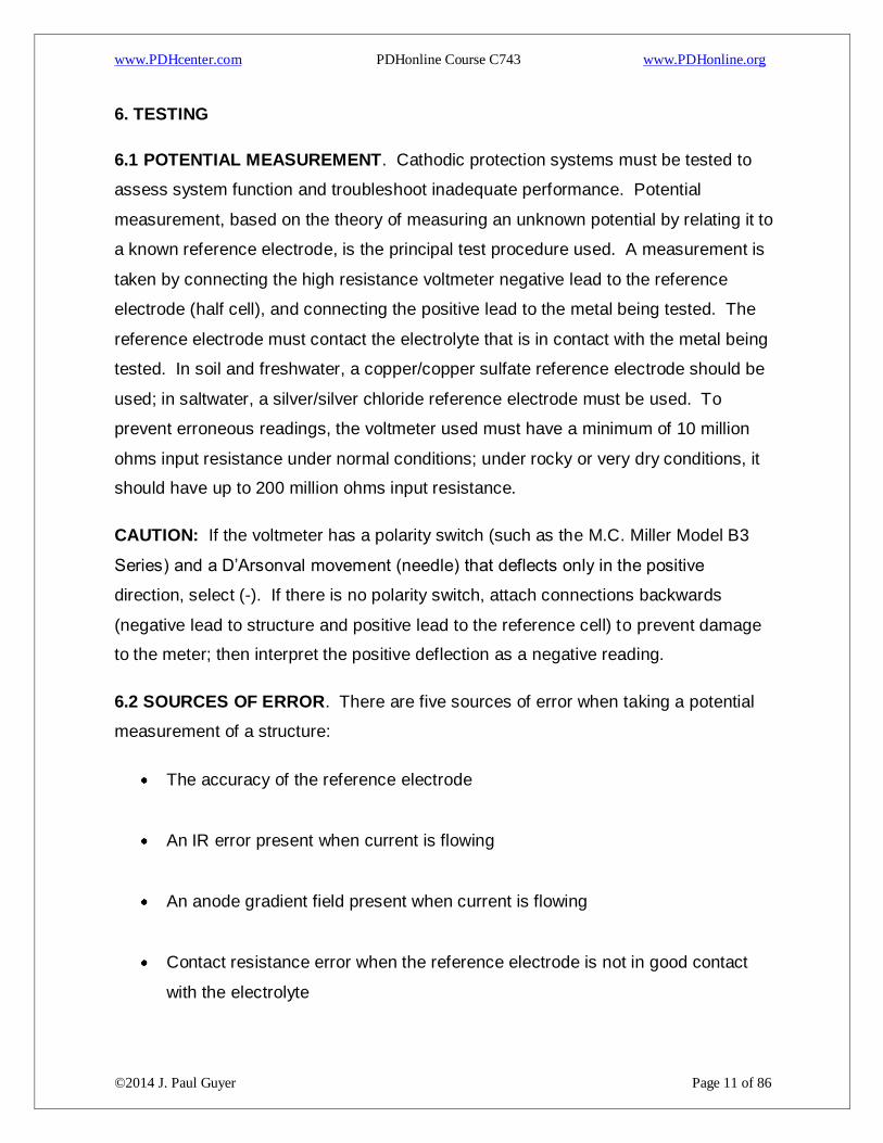
6.1 POTENTIAL MEASUREMENT. Cathodic protection systems must be tested to
assess system function and troubleshoot inadequate performance. Potential
measurement, based on the theory of measuring an unknown potential by relating it to
a known reference electrode, is the principal test procedure used. A measurement is
taken by connecting the high resistance voltmeter negative lead to the reference
electrode (half cell), and connecting the positive lead to the metal being tested. The
reference electrode must contact the electrolyte that is in contact with the metal being
tested. In soil and freshwater, a copper/copper sulfate reference electrode should be
used; in saltwater, a silver/silver chloride reference electrode must be used. To
prevent erroneous readings, the voltmeter used must have a minimum of 10 million
ohms input resistance under normal conditions; under rocky or very dry conditions, it
should have up to 200 million ohms input resistance.
CAUTION: If the voltmeter has a polarity switch (such as the M.C. Miller Model B3
Series) and a D’Arsonval movement (needle) that deflects only in the positive
direction, select (-). If there is no polarity switch, attach connections backwards
(negative lead to structure and positive lead to the reference cell) to prevent damage
to the meter; then interpret the positive deflection as a negative reading.
6.2 SOURCES OF ERROR. There are five sources of error when taking a potential
measurement of a structure:
The accuracy of the reference electrode
An IR error present when current is flowing
An anode gradient field present when current is flowing
Contact resistance error when the reference electrode is not in good contact
with the electrolyte

www.PDHcenter.com PDHonline Course C743 www.PDHonline.org
©2014 J. Paul Guyer Page 12 of 86
Influence of foreign structures (mixed potentials)
6.2.1 ACCURACY OF THE REFERENCE ELECTRODE. To prevent erroneous
potential measurements, the accuracy of the reference electrode (half cell) must be
reliable. A valid (tested) reference electrode must be used to take all potential
measurements. Proper maintenance of the half-cell is essential. If the electrolyte in
the half cell is contaminated, or the metallic electrode is contaminated or oxidized, the
potential of the cell changes.
Temperature also affects the potential of the reference cell. There is an
increase of approximately 0.9 mV per degree Celsius (0.5 mV per degree
Fahrenheit), so a measurement of -0.85 at 21 °C (70 °F) would read -0.835 at 4
°C (40 °F), and 0.865 at 38 °C (100 °F).
To determine the accuracy of a reference electrode, multiple reference
electrodes must be used. In practice, there should be one reference electrode
maintained properly, which is not used in the field, to check other reference
electrodes against before they are used in the field. This “reference” reference
electrode must be properly initiated and stored.
6.2.1.1 INITIATION OF A REFERENCE ELECTRODE. The copper/copper sulfate
reference electrode must be properly cleaned and initiated to ensure accuracy.
Improper cleaning or initiation can cause significant changes in the potential of the
reference (and subsequent errors in all measurements taken). The metal electrode
must be cleaned properly and the electrolyte solution must be prepared properly to
ensure accuracy.
www.PDHcenter.com PDHonline Course C743 www.PDHonline.org
©2014 J. Paul Guyer Page 13 of 86
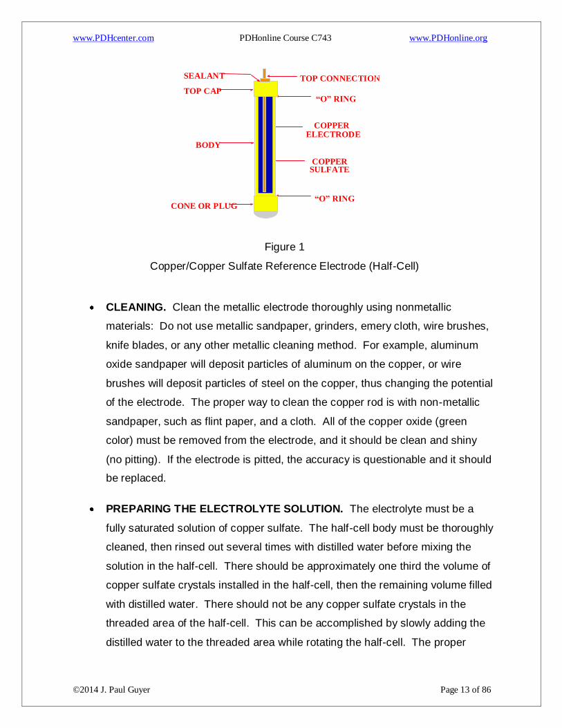
Figure 1
Copper/Copper Sulfate Reference Electrode (Half-Cell)
CLEANING. Clean the metallic electrode thoroughly using nonmetallic
materials: Do not use metallic sandpaper, grinders, emery cloth, wire brushes,
knife blades, or any other metallic cleaning method. For example, aluminum
oxide sandpaper will deposit particles of aluminum on the copper, or wire
brushes will deposit particles of steel on the copper, thus changing the potential
of the electrode. The proper way to clean the copper rod is with non-metallic
sandpaper, such as flint paper, and a cloth. All of the copper oxide (green
color) must be removed from the electrode, and it should be clean and shiny
(no pitting). If the electrode is pitted, the accuracy is questionable and it should
be replaced.
PREPARING THE ELECTROLYTE SOLUTION. The electrolyte must be a
fully saturated solution of copper sulfate. The half-cell body must be thoroughly
cleaned, then rinsed out several times with distilled water before mixing the
solution in the half-cell. There should be approximately one third the volume of
copper sulfate crystals installed in the half-cell, then the remaining volume filled
with distilled water. There should not be any copper sulfate crystals in the
threaded area of the half-cell. This can be accomplished by slowly adding the
distilled water to the threaded area while rotating the half-cell. The proper
TOP CAP
CONE OR PLUG
BODY
TOP CONNECTION
COPPER ELECTRODE
“O” RING
“O” RING
SEALANT
COPPER SULFATE
www.PDHcenter.com PDHonline Course C743 www.PDHonline.org
©2014 J. Paul Guyer Page 14 of 86
solution is a deep blue in color and after vigorous shaking; there must still be
some copper sulfate crystals that will not go into solution (fully saturated). If the
half-cell has been previously used, additional steps are required. All parts
should be inspected for cracks or other defects. O-rings should be replaced.
The cone or plug must be replaced. To provide additional protection from
subsequent leakage of the electrolyte from the half-cell, plumber’s tape can be
used on the threads of both the top cap and the end plug (new or used half
cells). If the copper electrode is removed from the end cap or replacement of
the end cap is required, the threads must be sealed with proper sealant when
reinstalled, to prevent leakage of the electrolyte.
TESTING. To determine the accuracy of a half-cell, use multiple reference
electrodes. Using a “reference” reference electrode, measure the difference in
potential to the half-cell under test. Use a meter on the millivolt scale, place the
two cells cone-to-cone, and measure the potential difference. The potential
difference should not be in excess of 5 mV. If no “reference” reference
electrode is available, follow the procedures in 7.2.1.1 for initiation of a
reference electrode on a new or used half-cell to get a reliable reference
electrode, then test the potential difference (in mV) to other half cells. When a
reference electrode is first initiated, allow sufficient time for the cone to become
saturated (up to two hours). Placing the half-cell, cone end down, in a container
of copper sulfate solution, can speed up the process.
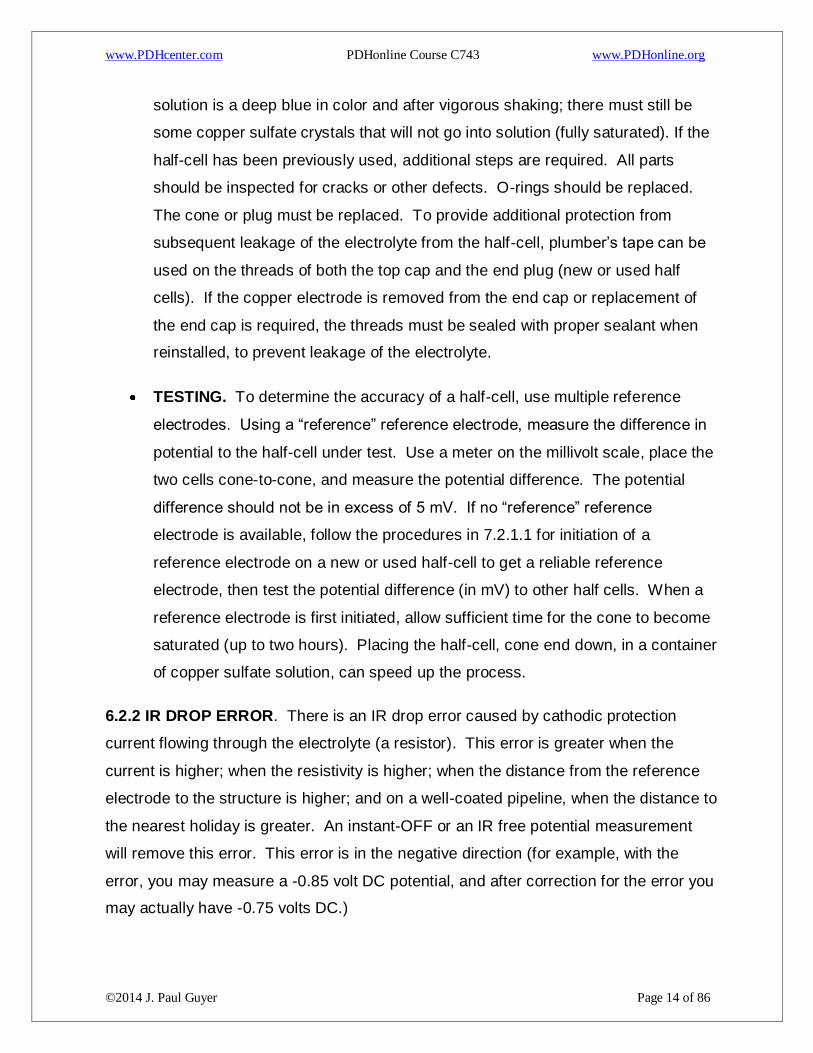
6.2.2 IR DROP ERROR. There is an IR drop error caused by cathodic protection
current flowing through the electrolyte (a resistor). This error is greater when the
current is higher; when the resistivity is higher; when the distance from the reference
electrode to the structure is higher; and on a well-coated pipeline, when the distance to
the nearest holiday is greater. An instant-OFF or an IR free potential measurement
will remove this error. This error is in the negative direction (for example, with the
error, you may measure a -0.85 volt DC potential, and after correction for the error you
may actually have -0.75 volts DC.)

www.PDHcenter.com PDHonline Course C743 www.PDHonline.org
©2014 J. Paul Guyer Page 15 of 86
www.PDHcenter.com PDHonline Course C743 www.PDHonline.org
©2014 J. Paul Guyer Page 16 of 86
Figure 2
IR Drop Error
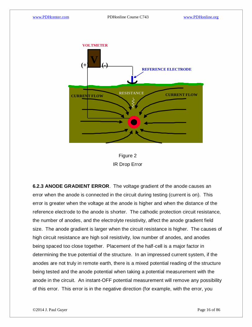
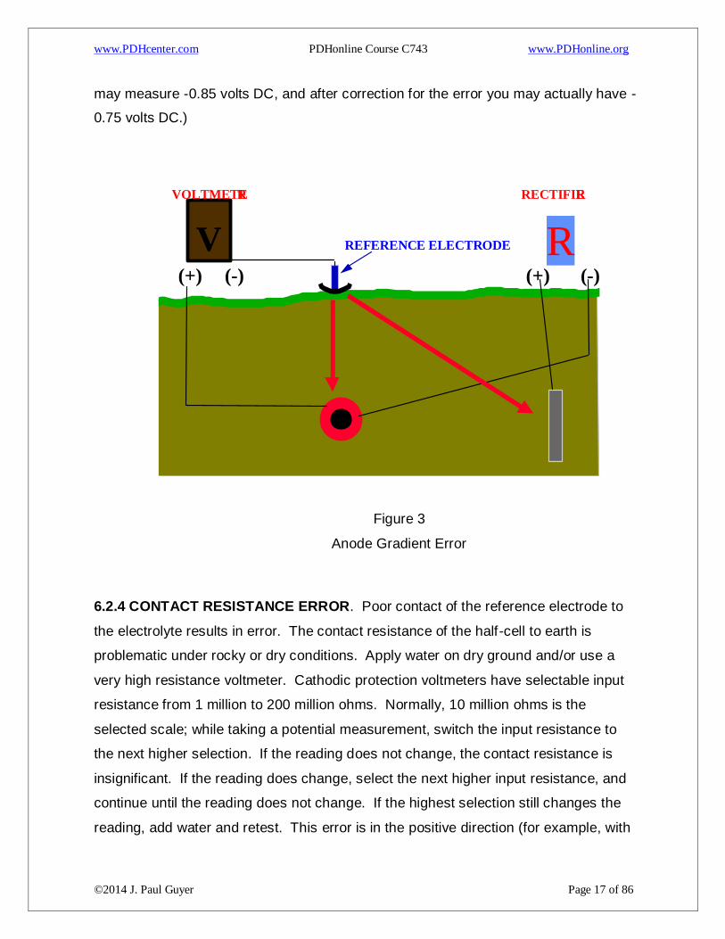
6.2.3 ANODE GRADIENT ERROR. The voltage gradient of the anode causes an
error when the anode is connected in the circuit during testing (current is on). This
error is greater when the voltage at the anode is higher and when the distance of the
reference electrode to the anode is shorter. The cathodic protection circuit resistance,
the number of anodes, and the electrolyte resistivity, affect the anode gradient field
size. The anode gradient is larger when the circuit resistance is higher. The causes of
high circuit resistance are high soil resistivity, low number of anodes, and anodes
being spaced too close together. Placement of the half-cell is a major factor in
determining the true potential of the structure. In an impressed current system, if the
anodes are not truly in remote earth, there is a mixed potential reading of the structure
being tested and the anode potential when taking a potential measurement with the
anode in the circuit. An instant-OFF potential measurement will remove any possibility
of this error. This error is in the negative direction (for example, with the error, you
V (-) (+)
REFERENCE ELECTRODE
VOLTMETER
CURRENT FLOW CURRENT FLOW RESISTANCE
www.PDHcenter.com PDHonline Course C743 www.PDHonline.org
©2014 J. Paul Guyer Page 17 of 86
may measure -0.85 volts DC, and after correction for the error you may actually have -
0.75 volts DC.)
Figure 3
Anode Gradient Error
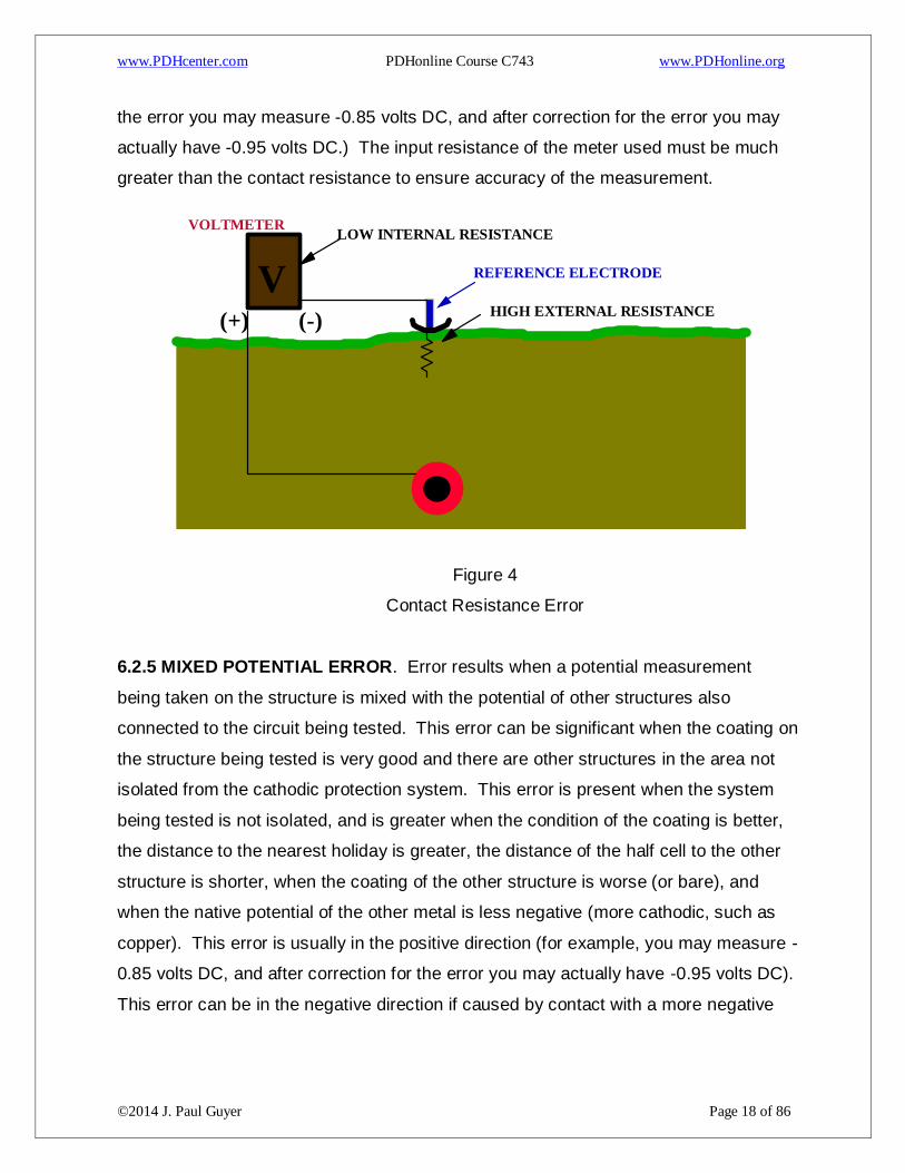
6.2.4 CONTACT RESISTANCE ERROR. Poor contact of the reference electrode to
the electrolyte results in error. The contact resistance of the half-cell to earth is
problematic under rocky or dry conditions. Apply water on dry ground and/or use a
very high resistance voltmeter. Cathodic protection voltmeters have selectable input
resistance from 1 million to 200 million ohms. Normally, 10 million ohms is the
selected scale; while taking a potential measurement, switch the input resistance to
the next higher selection. If the reading does not change, the contact resistance is
insignificant. If the reading does change, select the next higher input resistance, and
continue until the reading does not change. If the highest selection still changes the
reading, add water and retest. This error is in the positive direction (for example, with
V
(-) (+)
REFERENCE ELECTRODE
VOLTMETE R
(-) (+)
R
RECTIFIE R
www.PDHcenter.com PDHonline Course C743 www.PDHonline.org
©2014 J. Paul Guyer Page 18 of 86
the error you may measure -0.85 volts DC, and after correction for the error you may
actually have -0.95 volts DC.) The input resistance of the meter used must be much
greater than the contact resistance to ensure accuracy of the measurement.
Figure 4
Contact Resistance Error
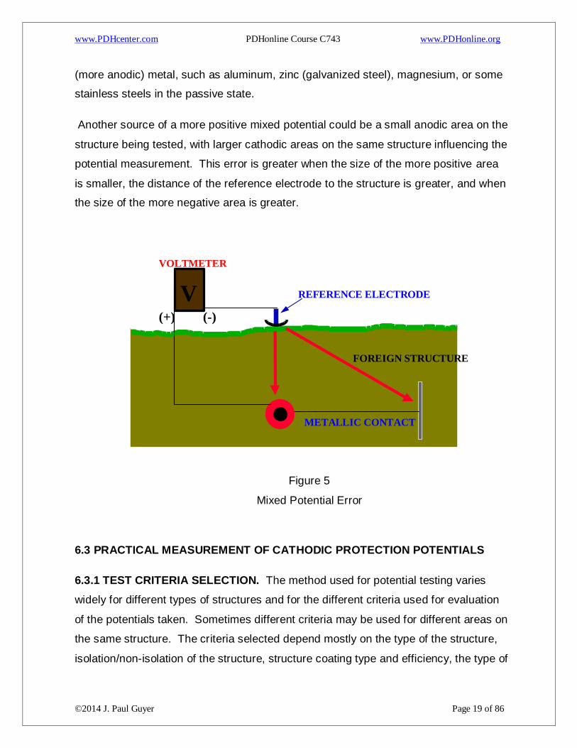
6.2.5 MIXED POTENTIAL ERROR. Error results when a potential measurement
being taken on the structure is mixed with the potential of other structures also
connected to the circuit being tested. This error can be significant when the coating on
the structure being tested is very good and there are other structures in the area not
isolated from the cathodic protection system. This error is present when the system
being tested is not isolated, and is greater when the condition of the coating is better,
the distance to the nearest holiday is greater, the distance of the half cell to the other
structure is shorter, when the coating of the other structure is worse (or bare), and
when the native potential of the other metal is less negative (more cathodic, such as
copper). This error is usually in the positive direction (for example, you may measure -
0.85 volts DC, and after correction for the error you may actually have -0.95 volts DC).
This error can be in the negative direction if caused by contact with a more negative
V
(-) (+)
REFERENCE ELECTRODE
VOLTMETER
HIGH EXTERNAL RESISTANCE
LOW INTERNAL RESISTANCE
www.PDHcenter.com PDHonline Course C743 www.PDHonline.org
©2014 J. Paul Guyer Page 19 of 86
(more anodic) metal, such as aluminum, zinc (galvanized steel), magnesium, or some
stainless steels in the passive state.
Another source of a more positive mixed potential could be a small anodic area on the
structure being tested, with larger cathodic areas on the same structure influencing the
potential measurement. This error is greater when the size of the more positive area
is smaller, the distance of the reference electrode to the structure is greater, and when
the size of the more negative area is greater.
Figure 5
Mixed Potential Error
6.3 PRACTICAL MEASUREMENT OF CATHODIC PROTECTION POTENTIALS
6.3.1 TEST CRITERIA SELECTION. The method used for potential testing varies
widely for different types of structures and for the different criteria used for evaluation
of the potentials taken. Sometimes different criteria may be used for different areas on
the same structure. The criteria selected depend mostly on the type of the structure,
isolation/non-isolation of the structure, structure coating type and efficiency, the type of
V
(-) (+)
REFERENCE ELECTRODE
VOLTMETER
METALLIC CONTACT
FOREIGN STRUCTURE
www.PDHcenter.com PDHonline Course C743 www.PDHonline.org
©2014 J. Paul Guyer Page 20 of 86
cathodic protection system, the soil resistivity, the amount of current supplied by the
CP system, and the instrumentation available for testing.
6.3.1.1 SACRIFICIAL CATHODIC PROTECTION SYSTEM . Generally, the criterion
for sacrificial CP systems is -0.85 ON. IR error must be compensated for, usually by
placing the reference electrode as near to the structure as possible (directly over the
pipeline or tank) and as remote as possible from any sacrificial anode. This, combined
with knowledge of the structure coating, soil resistivity, the size and spacing of the
anodes and the anode current, is usually enough to determine the adequacy of the CP
applied to the structure. If in doubt, or when potential readings are questionable,
excavate to allow placement of a temporary reference electrode or permanent
reference electrode as close as practical to the structure to further minimize any
possible IR error. Sacrificial systems are normally used in low soil resistivities (low IR
error), on well coated structures with a low current requirement (low IR error), and
because of the very small driving voltage (under one volt), have a very small amount
of current flow (low IR error). If the dielectric strength of the structure coating is not
good, the soil resistivity is relatively high, or the location or spacing of the anodes
makes it impossible to measure the structure potential remote from the anodes, other
criteria should be used or excavations made to properly place the reference electrode
to obtain a valid potential measurement. For very small and well-coated structures
(such as valves, elbows, and tie downs), use the 100 mV polarization criterion. For all
sacrificial systems, if the sacrificial system is designed to allow interrupting the current
from all anodes simultaneously, the -100 mV polarization criterion could be used. The
-0.85 instant OFF criterion is usually not attainable in most soil conditions with
sacrificial anodes, unless the native potential of the structure is very high and/or the
soil resistivity is very low. The -0.85V instant-OFF criterion should not be used for
sacrificial CP systems except in rare cases; use the 100 mV shift criterion or the -0.85
ON criterion (considering IR).
www.PDHcenter.com PDHonline Course C743 www.PDHonline.org
©2014 J. Paul Guyer Page 21 of 86
6.3.1.2 IMPRESSED CURRENT CATHODIC PROTECTION SYSTEM . The first
consideration for determining the criteria to use with impressed current CP systems is
the type of anode bed used.
For distributed anode impressed current systems, the -0.85 instant-OFF or the
100 mV polarization criterion should be used; the -0.85 ON criterion should not
be used. For structures with a high dielectric strength coating, the -0.85 instant-
OFF criterion may be the easiest to use, although the 100 mV polarization
criterion can be used. For structures which are bare, poorly coated, or have a
deteriorated coating, the 100 mV polarization criterion should be used.
For remote anode impressed current systems, all criteria, or a mixture of criteria
may be used. If the anodes are truly remote from the test point, the electrolyte
resistivity is low, the dielectric strength of the coating is high, and the circuit
resistance of the CP system is low, the -0.85 ON criterion (considering IR error)
is sufficient. Accounting for voltage drops other than those across the structure-
to-electrolyte boundary is usually accomplished by placing the reference
electrode as near to the structure as possible (directly over the pipeline or tank).
This, combined with knowledge of the dielectric strength or the structure
coating, size of the structure, the electrolyte resistivity, the distance and voltage
at the anodes, the rectifier output voltage, and the rectifier output current, is
usually enough to determine the adequacy of the CP applied to the structure. If
in doubt, or when potential readings are questionable, test the location using
another criterion, or excavate to locate a temporary reference electrode (or
install a permanent reference electrode) as close as practical to the structure to
further minimize any possible IR error. For structures with a high dielectric
strength coating, regardless of the electrolyte resistivity, distance from the
anodes, or the CP system circuit resistance, the -0.85 instant-OFF criterion may
be the easiest to use, although the 100 mV polarization criterion can be used.
For structures which are bare, poorly coated, or have a deteriorated coating, the
100 mV polarization criterion should be used.
www.PDHcenter.com PDHonline Course C743 www.PDHonline.org
©2014 J. Paul Guyer Page 22 of 86
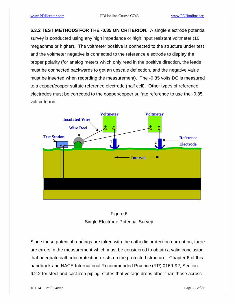
6.3.2 TEST METHODS FOR THE -0.85 ON CRITERION. A single electrode potential
survey is conducted using any high impedance or high input resistant voltmeter (10
megaohms or higher). The voltmeter positive is connected to the structure under test
and the voltmeter negative is connected to the reference electrode to display the
proper polarity (for analog meters which only read in the positive direction, the leads
must be connected backwards to get an upscale deflection, and the negative value
must be inserted when recording the measurement). The -0.85 volts DC is measured
to a copper/copper sulfate reference electrode (half cell). Other types of reference
electrodes must be corrected to the copper/copper sulfate reference to use the -0.85
volt criterion.
Figure 6
Single Electrode Potential Survey
Since these potential readings are taken with the cathodic protection current on, there
are errors in the measurement which must be considered to obtain a valid conclusion
that adequate cathodic protection exists on the protected structure. Chapter 6 of this
handbook and NACE International Recommended Practice (RP) 0169-92, Section
6.2.2 for steel and cast iron piping, states that voltage drops other than those across
Voltmeter
- +
1 2 Reference
Electrode
Test Station
Voltmeter
- +
Interval
Wire Reel
Insulated Wire
www.PDHcenter.com PDHonline Course C743 www.PDHonline.org
©2014 J. Paul Guyer Page 23 of 86
the structure-to-electrolyte boundary must be considered for valid interpretation of this
voltage measurement. Consideration is understood to mean the application of sound
engineering practice in determining the significance of voltage drops by methods such
as:
Measuring or calculating the voltage drop(s).
Reviewing the historical performance of the cathodic protection system.
Evaluating the physical and electrical characteristics of the pipe and its
environment.
Determining whether or not there is physical evidence of corrosion.
All the errors listed in above must be evaluated. Interruption of the CP current does
not fall under this criterion, since that would pertain to the -0.85 instant OFF or the 100
mV polarization criterion. Measuring or calculating the voltage drop(s) includes
measuring all the factors that affect the magnitude of the voltage errors present in the
ON reading. These measurements include the anode output, rectifier current output,
structure coating efficiency, location of the reference cell in relation to the anodes and
the structure, electrolyte resistivity, comparison to previous potentials (native, ON,
and/or instant OFF) and other factors which may contribute to the corrosion rate
(presence of stray current, interference, bi-metallic connections, pH, temperature,
homogeneity of the soil, amount of oxygen, presence of bacteria, and presence of
other ions or contaminants which may affect the corrosion rate). Implementation of
this criterion is only possible when these factors can be quantitatively verified by
measurement these factors, or historical evidence that these factors have been
considered. Factors that decrease magnitude of the voltage drop errors or otherwise
slow or stop the corrosion rate include:
www.PDHcenter.com PDHonline Course C743 www.PDHonline.org
©2014 J. Paul Guyer Page 24 of 86
High dielectric strength coating. A 99 percent to 99.7 percent effective coating
drastically lowers the amount of current to obtain adequate cathodic protection;
consequently IR error is also drastically lowered.
Low electrolyte resistivity. As resistivity is lowered, the IR drop error is lowered.
Also for impressed current systems, the circuit resistance is lower, resulting in a
lower voltage at the anode (to obtain the same current), lowering any anode
gradient errors.
High pH (7 to 13). A high pH in the electrolyte near the protected structure
indicates cathodic protection is present, but amphoteric materials could be
damaged by the high alkalinity created by the cathodic protection.
Low temperatures, which decrease the corrosion rate.
Current density.
Lack of bimetallic connections. If present they would raise the corrosion rate.
Lack of interference corrosion. Interference raises the potential in the pickup
area (lowers corrosion) and lowers the potential in the discharge area
(increases the corrosion rate).
6.3.3 TEST METHODS FOR THE -0.85 INSTANT-OFF CRITERION. For this
criterion, measurements of potential must be taken when there is no cathodic
protection current flowing. The measurement of the instant-OFF or the potential when
the cathodic protection is not flowing is required as the means of removing errors from
the measurement. For various methods used to measure the instant-OFF potential,
see paragraph 3.5. If the potential measurement meets or exceeds -0.85 volts DC (in
comparison to a copper/copper sulfate reference electrode) using these methods, this

www.PDHcenter.com PDHonline Course C743 www.PDHonline.org
©2014 J. Paul Guyer Page 25 of 86
criterion has been met. Other reference electrodes must be corrected to the factor for
a copper/copper sulfate reference to be valid under this criterion.
6.3.4 TEST METHODS FOR THE 100 MV POLARIZATION CRITERION. The test
method for this criterion is exactly like the method for the negative 0.85 instant-OFF
criterion, with the additional requirement of either comparing the measurements to a
native survey (potentials taken before the cathodic protection current was applied), or
allowing for the measurement of the polarization decay. It is recommended that the
native potentials be used to compare the instant-OFF readings for the 100 mV
polarization criterion. After cathodic protection has been applied, the structure is
polarized, and even after current interruption, considerable time may be required
before the potential returns to the native potential value. Measuring polarization decay
guarantees the proper shift, but may require considerably more current to polarize the
structure to a level where the 100 mV depolarization would occur in a relatively short
time.
6.3.5 INSTANT-OFF TEST METHODS. The test method used for an instant-OFF
potential measurement is determined by the type of equipment used and the type of
current interrupter used. The test method must include interruption of the protective
current or measurement of the potential when there is no current flowing, to guarantee
the removal of all IR drop and anode gradient errors. There are four different
equipment technologies that are used and several ways to accomplish the current
interruption (sometimes depending on the type of equipment being used). Types of
equipment include:
A normal high input impedance digital voltmeter may be used in combination
with conventional current interrupters, manually synchronizable, or advanced
synchronizable interrupters (not pulse generators, unless used as a
conventional interrupter).
A data logger which records potential measurements very quickly (from four to
several thousand readings per second) may be used in combination with
www.PDHcenter.com PDHonline Course C743 www.PDHonline.org
©2014 J. Paul Guyer Page 26 of 86
conventional current interrupters, manually synchronizable, or advanced
synchronizable interrupters (not pulse generators, unless used as a
conventional interrupter), then analyzing the data (sometimes using computer
software) to determine the instant-OFF potential reading.
A waveform analyzer may be used together with a pulse generator to calculate
the OFF potential.
A high speed data logger and oscilloscope (or similar very high speed recording
device) may be used to analyze the unfiltered signal on the structure to obtain
the potential of the structure when the DC output waveform is at zero current
output. This technology may only be applicable with potential measurements
that are affected by only one single-phase rectifier, with all filters and chokes
disconnected from the rectifier output and may not remove all anode gradient
errors.
6.3.6 TYPES OF INTERRUPTERS. The type of interrupter used depends on the
number of rectifiers or DC current sources and the type of equipment used to perform
the instant-OFF measurements. Manual interruption of a cathodic protection rectifier
using an AC power switch, rectifier circuit breaker, or other means is generally not
recommended. The time to manually open and close contacts, coupled with
interruption of the AC side of the circuit does not provide accurate or repeatable
measurements under many conditions within the first second of interruption, resulting
in significant inaccuracies in the measurement obtained. Manually operated relay
contacts are sometimes used, and may produce repeatable results if they have a quick
open and closed mechanism and are installed in the DC output of a rectifier. Using
radios to signal operators to open and close contacts, breakers or switches could also
produce erroneous readings due to RF signals from the radio which may induce
voltages in the meter being used to measure or record the measurement, especially
with analog meters or unfiltered digital meters.
www.PDHcenter.com PDHonline Course C743 www.PDHonline.org
©2014 J. Paul Guyer Page 27 of 86
6.3.6.1 CONVENTIONAL INTERRUPTER. The conventional current interrupter
provides for timed interruption of a rectifier DC output current. This is normally
accomplished by opening the circuit either between the anodes and the rectifier, or the
structure and the rectifier. Units normally provide independent control of open and
closed time intervals. Variations in the accuracy of the interruption timing, current
ratings of the relay contacts, and the selection increments of the on and off cycles vary
between units. These units are normally installed temporarily in the rectifier output
circuit during testing, but sometimes are optionally installed in the rectifier cabinet.
Quartz crystal controlled units are usually accurate to within one second a day. These
units are typically powered by batteries installed internally, or with an external DC
power source through a panel plug.
6.3.6.2 MANUALLY SYNCHRONIZABLE INTERRUPTER. This unit is similar to a
high quality conventional interrupter (may be accurate to within one tenth of a second
in 24 hours) with the additional feature of synchronizing the interruption cycle with
other like units. This is normally accomplished by using a supplied cable to
temporarily connect two units together, to start second, third, fourth, etc., units for
synchronization of the interruption cycles of all units. These units make it possible to
interrupt several rectifiers simultaneously to use various instruments to measure an
instant-OFF potential reading. They are usually portable, but could possibly be
installed equipment, with a portable unit used to synchronize the rectifier-installed
units.
6.3.6.3 ADVANCED SYNCHRONIZABLE INTERRUPTER. These units are similar to
a manually synchronizable interrupter with the means of synchronization controlled by
some communication technology (versus manually by cable connection) such as radio,
computer connection, modem, or satellite transmissions. They are usually
permanently installed, but portable units are also available.
6.3.6.4 PULSE GENERATOR. The pulse generator can normally be used as a
conventional current interrupter or as a standard pulse generator. They may be
permanently or temporarily installed in the rectifier cabinet. They do not require
www.PDHcenter.com PDHonline Course C743 www.PDHonline.org
©2014 J. Paul Guyer Page 28 of 86
synchronization when used together with the proper waveform analyzing equipment. If
used for a conventional current interrupter, they are not synchronizable, but usually
provide for user-selectable interrupt cycles. The standard pulse generator is
connected in series in the DC output (either positive or negative) of the rectifier(s) and
produces a precisely timed, zero-current pulse that does not drift. AC supply voltage
is used to power the pulse generator. Selectable input AC power units must be set for
the correct AC supply voltage being used. Ensure the pulse generator is set to the
proper voltage before applying AC power, or the pulse generator will be damaged.
6.3.7 SPECIFIC METHODS FOR VARIOUS INSTANT-OFF POTENTIAL
MEASUREMENT TECHNIQUES
6.3.7.1 USING NORMAL DIGITAL VOLTMETER WITH CURRENT
INTERRUPTER(S). The digital voltmeter may be used together with a current
interrupter to measure an instant-OFF potential. For locations that are affected by
more than one rectifier or DC current source, synchronized interruption must be
accomplished. For locations that are affected by more than three to six rectifiers or
DC current sources (according to their contribution or availability of synchronizable
interrupters), subsequent systems can be turned off to preclude their contribution to
the instant-OFF reading.
www.PDHcenter.com PDHonline Course C743 www.PDHonline.org
©2014 J. Paul Guyer Page 29 of 86
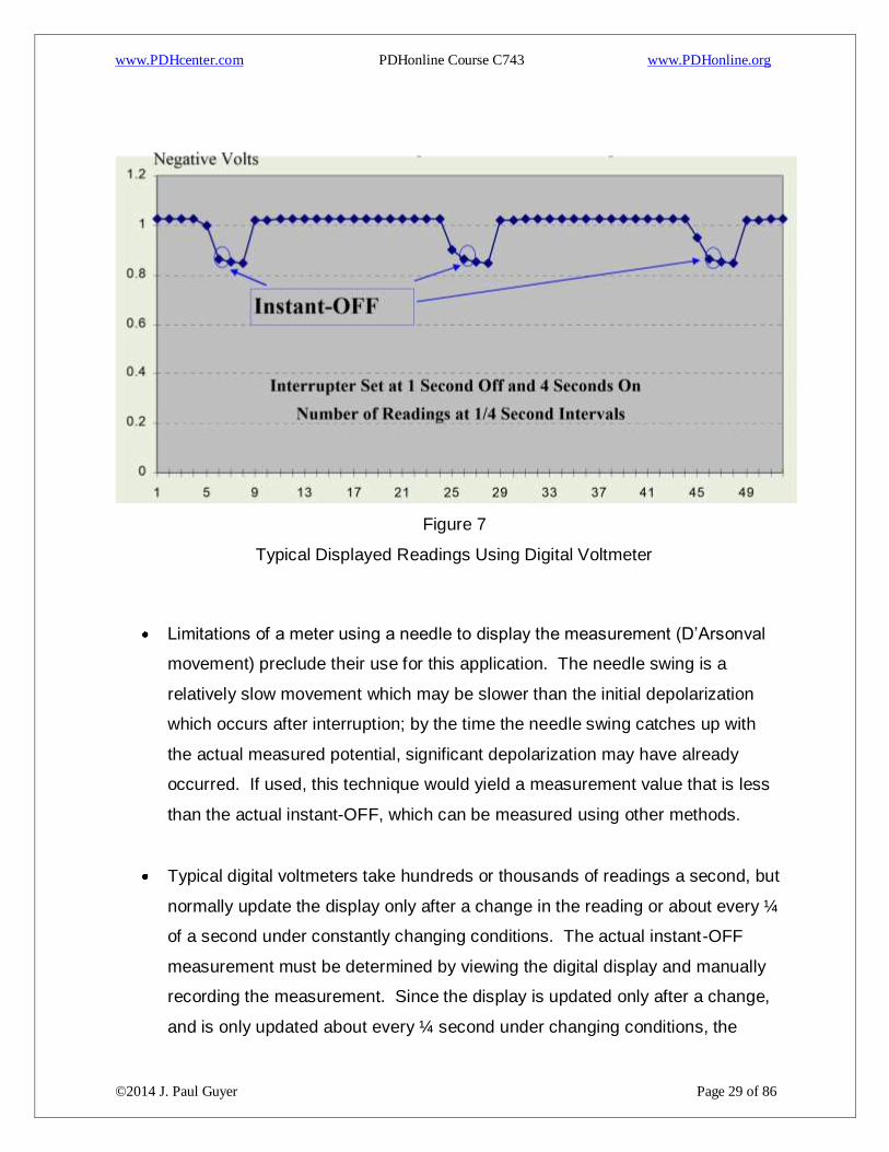
Figure 7
Typical Displayed Readings Using Digital Voltmeter
Limitations of a meter using a needle to display the measurement (D’Arsonval
movement) preclude their use for this application. The needle swing is a
relatively slow movement which may be slower than the initial depolarization
which occurs after interruption; by the time the needle swing catches up with
the actual measured potential, significant depolarization may have already
occurred. If used, this technique would yield a measurement value that is less
than the actual instant-OFF, which can be measured using other methods.
Typical digital voltmeters take hundreds or thousands of readings a second, but
normally update the display only after a change in the reading or about every ¼
of a second under constantly changing conditions. The actual instant-OFF
measurement must be determined by viewing the digital display and manually
recording the measurement. Since the display is updated only after a change,
and is only updated about every ¼ second under changing conditions, the
www.PDHcenter.com PDHonline Course C743 www.PDHonline.org
©2014 J. Paul Guyer Page 30 of 86
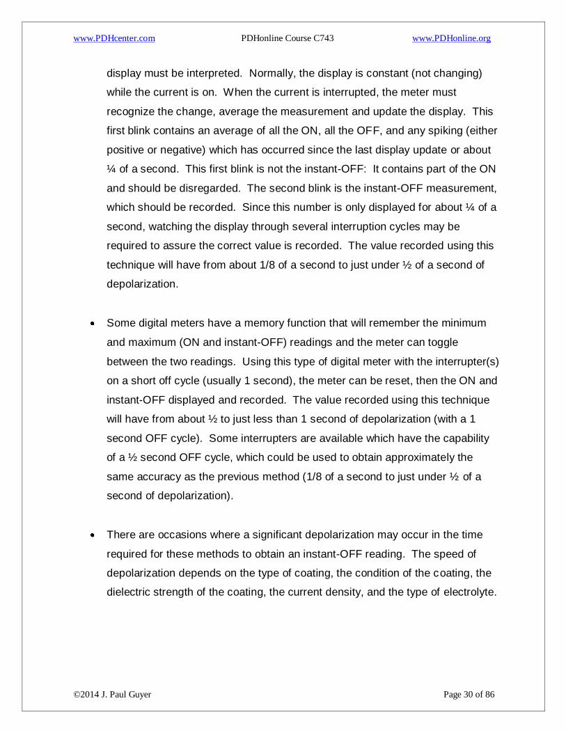
display must be interpreted. Normally, the display is constant (not changing)
while the current is on. When the current is interrupted, the meter must
recognize the change, average the measurement and update the display. This
first blink contains an average of all the ON, all the OFF, and any spiking (either
positive or negative) which has occurred since the last display update or about
¼ of a second. This first blink is not the instant-OFF: It contains part of the ON
and should be disregarded. The second blink is the instant-OFF measurement,
which should be recorded. Since this number is only displayed for about ¼ of a
second, watching the display through several interruption cycles may be
required to assure the correct value is recorded. The value recorded using this
technique will have from about 1/8 of a second to just under ½ of a second of
depolarization.
Some digital meters have a memory function that will remember the minimum
and maximum (ON and instant-OFF) readings and the meter can toggle
between the two readings. Using this type of digital meter with the interrupter(s)
on a short off cycle (usually 1 second), the meter can be reset, then the ON and
instant-OFF displayed and recorded. The value recorded using this technique
will have from about ½ to just less than 1 second of depolarization (with a 1
second OFF cycle). Some interrupters are available which have the capability
of a ½ second OFF cycle, which could be used to obtain approximately the
same accuracy as the previous method (1/8 of a second to just under ½ of a
second of depolarization).
There are occasions where a significant depolarization may occur in the time
required for these methods to obtain an instant-OFF reading. The speed of
depolarization depends on the type of coating, the condition of the coating, the
dielectric strength of the coating, the current density, and the type of electrolyte.

www.PDHcenter.com PDHonline Course C743 www.PDHonline.org
©2014 J. Paul Guyer Page 31 of 86
Figure 8
Readings Recorded by Digital Voltmeter with Minimum/Maximum Function (Reference
Cell to Meter Negative, Structure to Meter Positive)
6.3.7.2 USING A DATA LOGGER WITH CURRENT INTERRUPTERS. As with digital
meters, current interruption is required. The data logger records from four to several
thousand readings per second. The measurements taken are not an average over
time as with the digital meters. The location being tested is measured through at least
one OFF cycle and the instant-OFF reading is extracted manually from the data, or
extracted via a computer program that is designed for that purpose. Any positive or
negative spiking that may occur when the current is interrupted or when it goes back
on should be disregarded and is not considered a valid instant-OFF reading. Fast
data loggers record more data resulting in a higher accuracy, but often require more
time to extrapolate the correct reading. Very fast data loggers may require software
analysis of the data to get the instant-OFF readings in a timely manner. Manually
verify a representative sampling of the data to ensure the software is effectively
extrapolating the correct reading. The value recorded using this technique will have
from about zero (0.0003 seconds at 3000 per second) to under ¼ of a second (at four
per second) of depolarization, according to the sampling speed of the data logger. It is
possible at four readings per second to record a positive or negative spike as one of
www.PDHcenter.com PDHonline Course C743 www.PDHonline.org
©2014 J. Paul Guyer Page 32 of 86
the readings (depending on synchronization timing and the sampling timing of the data
logger). In that case, the next reading would have a full ¼ second of depolarization.
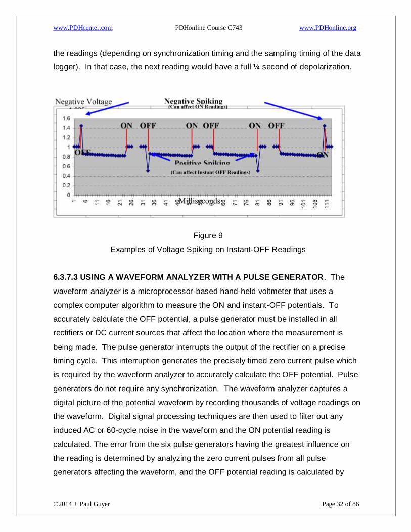
Figure 9
Examples of Voltage Spiking on Instant-OFF Readings
6.3.7.3 USING A WAVEFORM ANALYZER WITH A PULSE GENERATOR. The
waveform analyzer is a microprocessor-based hand-held voltmeter that uses a
complex computer algorithm to measure the ON and instant-OFF potentials. To
accurately calculate the OFF potential, a pulse generator must be installed in all
rectifiers or DC current sources that affect the location where the measurement is
being made. The pulse generator interrupts the output of the rectifier on a precise
timing cycle. This interruption generates the precisely timed zero current pulse which
is required by the waveform analyzer to accurately calculate the OFF potential. Pulse
generators do not require any synchronization. The waveform analyzer captures a
digital picture of the potential waveform by recording thousands of voltage readings on
the waveform. Digital signal processing techniques are then used to filter out any
induced AC or 60-cycle noise in the waveform and the ON potential reading is
calculated. The error from the six pulse generators having the greatest influence on
the reading is determined by analyzing the zero current pulses from all pulse
generators affecting the waveform, and the OFF potential reading is calculated by

www.PDHcenter.com PDHonline Course C743 www.PDHonline.org
©2014 J. Paul Guyer Page 33 of 86
subtracting the error from the ON reading. If the location under test is suspected to
have more than six rectifiers or DC current sources significantly affecting the potential,
separate testing should be conducted to verify or eliminate that possibility. If there are
more than six sources of current affecting the potential at a particular location,
determine the six sources with the greatest influence and turn the rest off so that their
effect is not considered as part of the off potential. The value recorded using this
technique will have very little or no depolarization in the measurement.
6.3.7.4 USING A HIGH SPEED DATA LOGGER AND A FILTERED
OSCILLOSCOPE. The oscilloscope is used to analyze the rectifier output waveform,
and the high-speed data logger is used to obtain a digital picture of the potential signal
on the structure. This technology simultaneously measures the rectifier output
waveform and the potential waveform, and by comparison extrapolates the potential
measurement when the rectifier waveform is at zero current. This technology may
only be applicable with potential measurements that are affected by only one single-
phase rectifier, with all filters and chokes disconnected from the rectifier output. Since
the data logger is connected to the structure with a closed circuit to the anodes
through the rectifier, the potential of the anodes could still affect the potential
measurement if readings are taken in the vicinity of the anodes. On a well-coated
structure, the distance required to remove the possibility of a mixed potential (anode
and structure) would be greater. This technology will not work with a three-phase
rectifier system or where more than one rectifier is protecting the structure.
6.4 STRUCTURE-TO-SOIL POTENTIAL LIMITS
6.4.1 EXCESSIVE CATHODIC PROTECTION CURRENT. Excessive cathodic
protection current produces hydrogen gas evolution at the surface of the cathode. If
the gas is produced faster than it can permeate the coating, bubbling of the coating will
occur. The amount of coating damage is dependent on the amount of gas generated
and the type of coating. This condition is normally called “blowing off” the coating.
When this occurs, more of the structure is exposed to the electrolyte and the circuit
resistance between the anodes and the cathode becomes lower. This causes more
www.PDHcenter.com PDHonline Course C743 www.PDHonline.org
©2014 J. Paul Guyer Page 34 of 86
current to be impressed to this location, and usually, more gas evolution. This
phenomenon results in more coating damage and is very detrimental to current
distribution, since more current goes to that location, and less current goes to other,
more remote, locations.
6.4.2 WATER STORAGE TANKS. The coatings used in water storage tanks are the
most prone to this damage. This type of coating disbonds very easily as compared to
coatings used on underground structures. It is not uncommon for elevated or ground
level water storage tanks to have the coatings bubbled or blown off from excessive
cathodic protection. It is essential on these tanks to maintain the level of current at a
safe level. The accuracy of permanent reference electrodes used with automatic
systems should be of concern when performing the CP System Check. The ON
potentials of coated water storage tanks have many errors in the measurement
(paragraph 2.3). ON potential measurements over -1.10 volts DC to a copper/copper
sulfate reference electrode should be suspected of coating damage and instant-OFF
potentials taken. Coating damage should be expected when the potential
measurement is over -1.50 volts DC to a copper/copper sulfate reference electrode
and instant-OFF potentials must be taken. The instant-OFF potentials should not
exceed -1.00 volt DC and must never exceed -1.10 volts DC to a copper/copper
sulfate reference electrode.
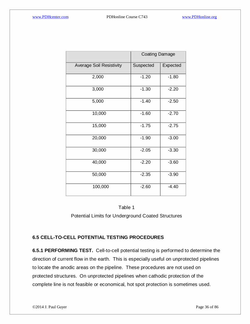
6.4.3 UNDERGROUND STRUCTURES. Coatings for underground structures are
generally resistant to this damage. The ON potentials of underground structures also
have many errors in the measurement (paragraph 2.3). ON potential measurements
to a copper/copper sulfate reference electrode should be suspected of coating
damage if over the potentials listed in Table 23 “SUSPECTED” column, and instant-
OFF potentials should be taken. Coating damage should be expected when the
potential measurement is over the potential listed in Table 23, “EXPECTED” column,
and instant OFF potentials must be taken. This figure assumes an IR drop error and is
given for information only. The only true way to measure this possible damage is with
an error-free measurement (paragraph 3). Instant-OFF measurements should be
used whenever possible. Instant-OFF measurements that are over approximately -
www.PDHcenter.com PDHonline Course C743 www.PDHonline.org
©2014 J. Paul Guyer Page 35 of 86
1.22 volts DC are not theoretically possible. If instant-OFF readings are significantly
over -1.22 volts DC, other DC current sources are present. Synchronous interruption
of all current sources must be accomplished.
For fusion-bonded coatings, the instant-OFF potentials should not exceed 1.07
volts DC and must never exceed -1.12 volts DC to a copper/copper sulfate
reference electrode.
For coal tar coatings, the instant-OFF potentials should not exceed -1.12 volts
DC and must never exceed -1.20 volts DC to a copper/copper sulfate reference
electrode.
For plastic tape coatings, the instant-OFF potentials should not exceed -1.02
volts DC and must never exceed -1.07 volts DC to a copper/copper sulfate
reference electrode.
For other coatings, refer to specifications for cathodic disbondment properties
compared to above coatings.
6.4.4 UNCOATED STRUCTURES. For uncoated structures, there are no theoretical
potential limits. Instant-OFF readings over -1.00 generally waste power and anode
material. Instant-OFF measurements that are over approximately -1.22 volts DC are
not theoretically possible. If instant-OFF readings are significantly over -1.22 volts DC,
other DC current sources are present. Synchronous interruption of all current sources
must be accomplished.
www.PDHcenter.com PDHonline Course C743 www.PDHonline.org
©2014 J. Paul Guyer Page 36 of 86
Coating Damage
Average Soil Resistivity Suspected Expected
2,000 -1.20 -1.80
3,000 -1.30 -2.20
5,000 -1.40 -2.50
10,000 -1.60 -2.70
15,000 -1.75 -2.75
20,000 -1.90 -3.00
30,000 -2.05 -3.30
40,000 -2.20 -3.60
50,000 -2.35 -3.90
100,000 -2.60 -4.40
Table 1
Potential Limits for Underground Coated Structures
6.5 CELL-TO-CELL POTENTIAL TESTING PROCEDURES
6.5.1 PERFORMING TEST. Cell-to-cell potential testing is performed to determine the
direction of current flow in the earth. This is especially useful on unprotected pipelines
to locate the anodic areas on the pipeline. These procedures are not used on
protected structures. On unprotected pipelines when cathodic protection of the
complete line is not feasible or economical, hot spot protection is sometimes used.
www.PDHcenter.com PDHonline Course C743 www.PDHonline.org
©2014 J. Paul Guyer Page 37 of 86
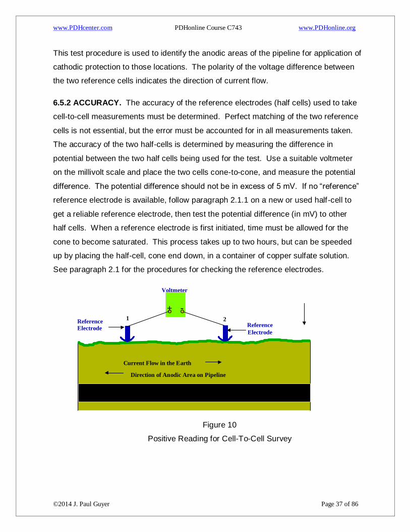
This test procedure is used to identify the anodic areas of the pipeline for application of
cathodic protection to those locations. The polarity of the voltage difference between
the two reference cells indicates the direction of current flow.
6.5.2 ACCURACY. The accuracy of the reference electrodes (half cells) used to take
cell-to-cell measurements must be determined. Perfect matching of the two reference
cells is not essential, but the error must be accounted for in all measurements taken.
The accuracy of the two half-cells is determined by measuring the difference in
potential between the two half cells being used for the test. Use a suitable voltmeter
on the millivolt scale and place the two cells cone-to-cone, and measure the potential
difference. The potential difference should not be in excess of 5 mV. If no “reference”
reference electrode is available, follow paragraph 2.1.1 on a new or used half-cell to
get a reliable reference electrode, then test the potential difference (in mV) to other
half cells. When a reference electrode is first initiated, time must be allowed for the
cone to become saturated. This process takes up to two hours, but can be speeded
up by placing the half-cell, cone end down, in a container of copper sulfate solution.
See paragraph 2.1 for the procedures for checking the reference electrodes.
Figure 10
Positive Reading for Cell-To-Cell Survey
Voltmeter
- + 1 2
Reference Electrode
Electrode
Reference
Current Flow in the Earth
Direction of Anodic Area on Pipeline
www.PDHcenter.com PDHonline Course C743 www.PDHonline.org
©2014 J. Paul Guyer Page 38 of 86
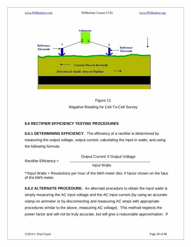
Figure 11
Negative Reading for Cell-To-Cell Survey
6.6 RECTIFIER EFFICIENCY TESTING PROCEDURES
6.6.1 DETERMINING EFFICIENCY. The efficiency of a rectifier is determined by
measuring the output voltage, output current, calculating the input in watts, and using
the following formula:
Output Current X Output Voltage
Rectifier Efficiency = Input Watts
**Input Watts = Revolutions per hour of the kWh meter disc X factor shown on the face of the kWh meter.
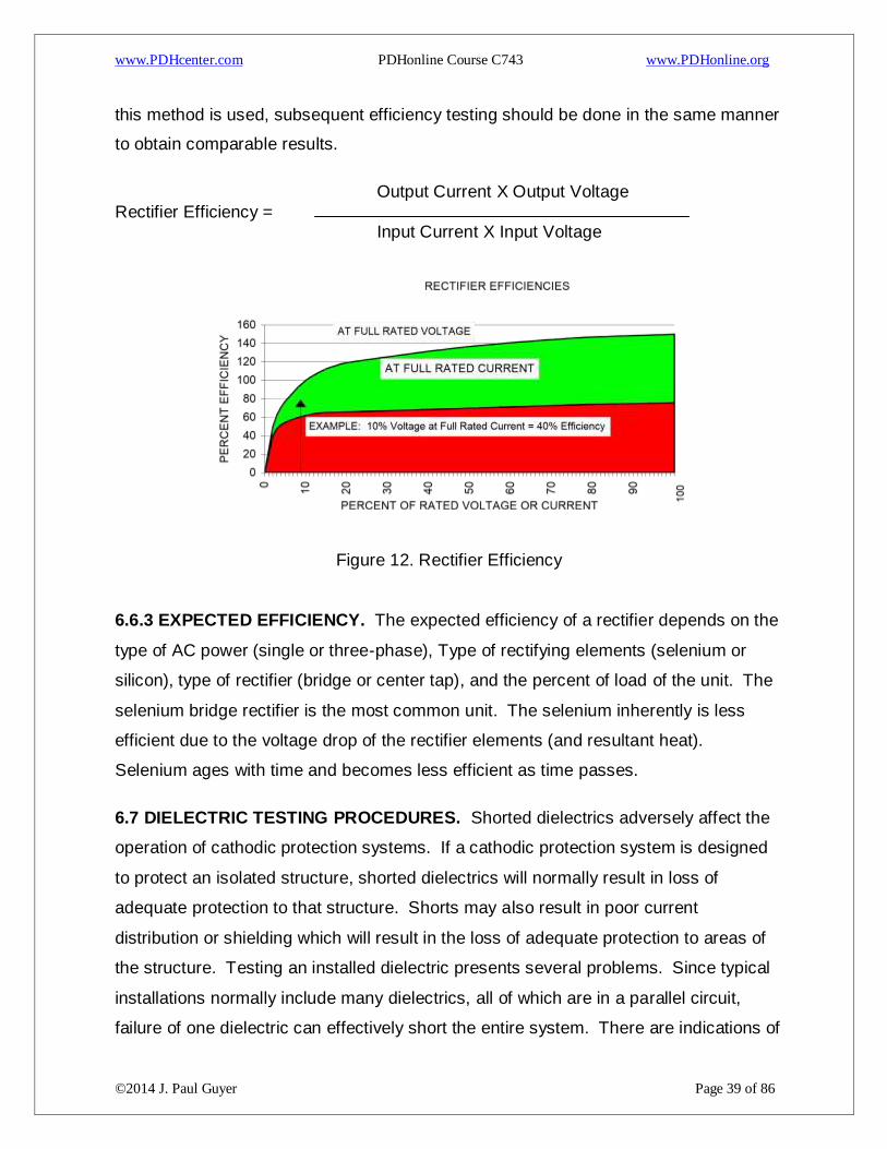
6.6.2 ALTERNATE PROCEDURE. An alternate procedure to obtain the input watts is
simply measuring the AC input voltage and the AC input current (by using an accurate
clamp-on ammeter or by disconnecting and measuring AC amps with appropriate
procedures similar to the above, measuring AC voltage). This method neglects the
power factor and will not be truly accurate, but will give a reasonable approximation. If
Voltmeter
- +
1 2 Reference
Electrode Electrode
Reference
Current Flow in the Earth
Direction of Anodic Area on Pipeline
www.PDHcenter.com PDHonline Course C743 www.PDHonline.org
©2014 J. Paul Guyer Page 39 of 86
this method is used, subsequent efficiency testing should be done in the same manner
to obtain comparable results.
Output Current X Output Voltage
Rectifier Efficiency = Input Current X Input Voltage
Figure 12. Rectifier Efficiency
6.6.3 EXPECTED EFFICIENCY. The expected efficiency of a rectifier depends on the
type of AC power (single or three-phase), Type of rectifying elements (selenium or
silicon), type of rectifier (bridge or center tap), and the percent of load of the unit. The
selenium bridge rectifier is the most common unit. The selenium inherently is less
efficient due to the voltage drop of the rectifier elements (and resultant heat).
Selenium ages with time and becomes less efficient as time passes.
6.7 DIELECTRIC TESTING PROCEDURES. Shorted dielectrics adversely affect the
operation of cathodic protection systems. If a cathodic protection system is designed
to protect an isolated structure, shorted dielectrics will normally result in loss of
adequate protection to that structure. Shorts may also result in poor current
distribution or shielding which will result in the loss of adequate protection to areas of
the structure. Testing an installed dielectric presents several problems. Since typical
installations normally include many dielectrics, all of which are in a parallel circuit,
failure of one dielectric can effectively short the entire system. There are indications of
www.PDHcenter.com PDHonline Course C743 www.PDHonline.org
©2014 J. Paul Guyer Page 40 of 86
the shorted condition of one dielectric at many, or all, other dielectrics installed.
Usually, the further the distance is between the dielectric being tested and the
dielectric that is shorted, the easier it is to test that dielectric. Most methods of testing
a dielectric give a reliable indication of only one condition of the dielectric (either
shorted or not shorted condition) and further testing may be required for the other
condition. Only one method gives a totally reliable indication of an installed dielectric.
The radio frequency tester (insulated flange tester), because of its wavelength and the
strength of the signal, gives a true indication of the condition of that specific dielectric.
This method will not read through other parallel paths, even when these paths are in
the immediate vicinity. In fact, this method can pinpoint the fault to a particular flange
bolt or the flange gasket.
Therefore, this method should be used for testing when any other method is not
conclusive. The preferred method to determine if a dielectric may be shorted is by
potential testing. This method will normally provide an immediate indication if the
dielectric is not shorted, and at the same time provide valuable potential data. If this
method indicates the dielectric may be shorted, other methods of verification are be
required. The radio frequency tester (insulated flange tester) should be used when a
shorted condition is indicated by potential measurements. Alternate methods of
verification may be used to test installed dielectrics. These methods include the pipe
locator method, which can determine that an installed dielectric is bad, but does not
give conclusive evidence if the test indicates that the dielectric is good; and the power
supply method, which can determine that an installed dielectric is good, but does not
give conclusive evidence if the test indicates that an installed dielectric is bad.
CAUTION: Do not use an ohmmeter to measure resistance of an installed dielectric.
If the dielectric is good, current will flow through the meter and damage could result. If
that current does not damage the meter, the measurement would not indicate a
resistance value. The voltage would be interpreted by the meter as coming from the
internal battery instead of the external electrical circuit being measured.
www.PDHcenter.com PDHonline Course C743 www.PDHonline.org
©2014 J. Paul Guyer Page 41 of 86
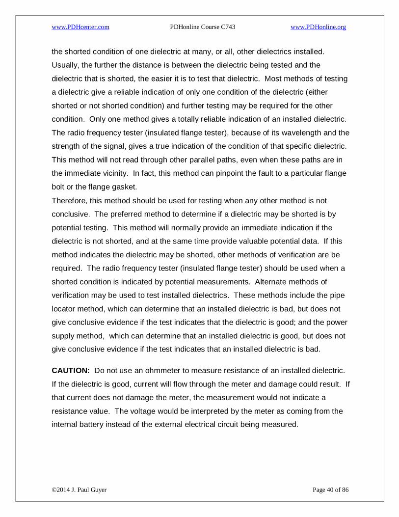
6.7.1 TESTING FOR A SHORTED DIELECTRIC. Take a potential measurement of
both sides of the installed dielectric by changing only the structure connection, without
moving the copper/copper sulfate reference electrode.
Figure 13
Testing for a Shorted Dielectric
If the two potential measurements are significantly different (over 10 mV), the
dielectric is good. The street side of the dielectric, under normal conditions
(with cathodic protection) should be at a potential more negative than -0.85
volts DC and the house side of the dielectric should be between approximately
-0.15 volts DC and -0.45 volts DC (a difference of between 400 and 700 mV).
If the dielectric is good and the house side of the dielectric has a potential more
negative than expected, another shorted dielectric in the area should be
suspected, and further investigation is required (for example, if the house side
potential reading is over -0.65, with a street side potential the same or more
negative).
If the two potential measurements are not significantly different (under 10 mV),
the dielectric may be shorted and additional testing is required. The preferred
Voltmeter
- +
1
2 Reference Electrode
Test Station or Metallic Contact
House Side of Dielectric
Street Side of Dielectric
to Pipeline
www.PDHcenter.com PDHonline Course C743 www.PDHonline.org
©2014 J. Paul Guyer Page 42 of 86
method is to use a radio frequency tester (insulated flange tester) to test that
specific dielectric. Other possible methods that may or may not be conclusive
include using the pipe locator method or the power supply method.
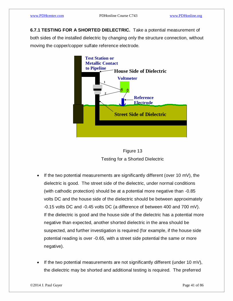
6.7.2 USING A RADIO FREQUENCY TESTER. This method is the most accurate
and conclusive method of testing a dielectric. Turn the insulated flange tester test
switch to “zero,” turn the control knob on, and zero the needle indicator. Turn the test
switch to “test,” and without turning the control knob, test the dielectric.
Figure 14
Testing an Installed Dielectric with the Insulated Flange Tester
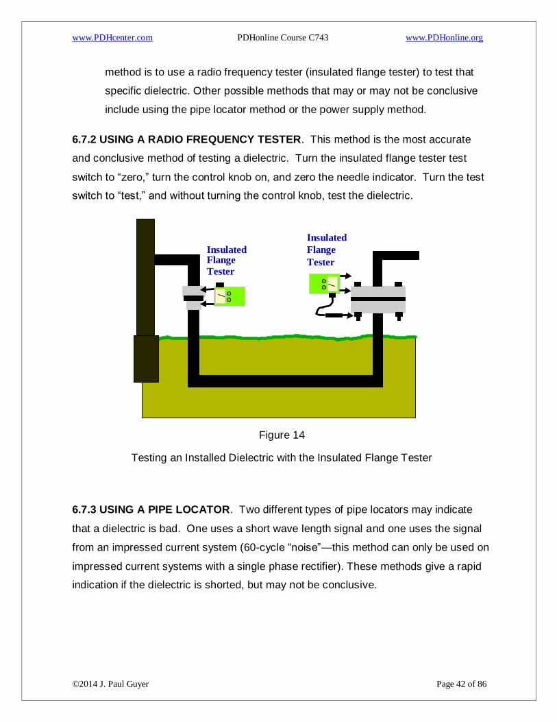
6.7.3 USING A PIPE LOCATOR. Two different types of pipe locators may indicate
that a dielectric is bad. One uses a short wave length signal and one uses the signal
from an impressed current system (60-cycle “noise”—this method can only be used on
impressed current systems with a single phase rectifier). These methods give a rapid
indication if the dielectric is shorted, but may not be conclusive.
Insulated Flange Tester
Insulated Flange
Tester
www.PDHcenter.com PDHonline Course C743 www.PDHonline.org
©2014 J. Paul Guyer Page 43 of 86
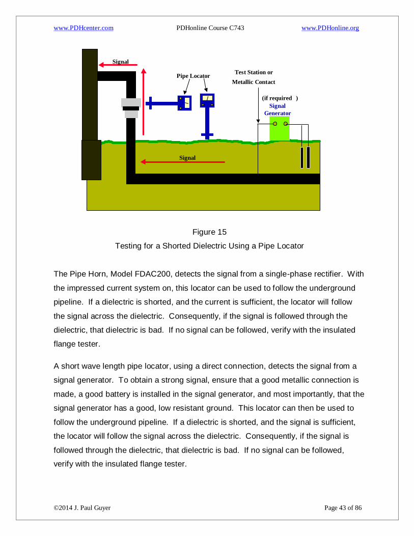
Figure 15
Testing for a Shorted Dielectric Using a Pipe Locator
The Pipe Horn, Model FDAC200, detects the signal from a single-phase rectifier. With
the impressed current system on, this locator can be used to follow the underground
pipeline. If a dielectric is shorted, and the current is sufficient, the locator will follow
the signal across the dielectric. Consequently, if the signal is followed through the
dielectric, that dielectric is bad. If no signal can be followed, verify with the insulated
flange tester.
A short wave length pipe locator, using a direct connection, detects the signal from a
signal generator. To obtain a strong signal, ensure that a good metallic connection is
made, a good battery is installed in the signal generator, and most importantly, that the
signal generator has a good, low resistant ground. This locator can then be used to
follow the underground pipeline. If a dielectric is shorted, and the signal is sufficient,
the locator will follow the signal across the dielectric. Consequently, if the signal is
followed through the dielectric, that dielectric is bad. If no signal can be followed,
verify with the insulated flange tester.
Test Station or
Signal
Signal
Metallic Contact
Signal Generator
( if required )
Pipe Locator

www.PDHcenter.com PDHonline Course C743 www.PDHonline.org
©2014 J. Paul Guyer Page 44 of 86
www.PDHcenter.com PDHonline Course C743 www.PDHonline.org
©2014 J. Paul Guyer Page 45 of 86
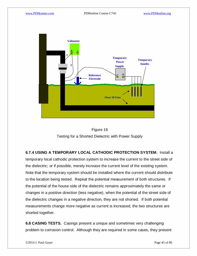
Figure 16
Testing for a Shorted Dielectric with Power Supply
6.7.4 USING A TEMPORARY LOCAL CATHODIC PROTECTION SYSTEM. Install a
temporary local cathodic protection system to increase the current to the street side of
the dielectric; or if possible, merely increase the current level of the existing system.
Note that the temporary system should be installed where the current should distribute
to the location being tested. Repeat the potential measurement of both structures. If
the potential of the house side of the dielectric remains approximately the same or
changes in a positive direction (less negative), when the potential of the street side of
the dielectric changes in a negative direction, they are not shorted. If both potential
measurements change more negative as current is increased, the two structures are
shorted together.
6.8 CASING TESTS. Casings present a unique and sometimes very challenging
problem to corrosion control. Although they are required in some cases, they present
Voltmeter
- + 1
2
Reference Electrode
- +
Temporary
Supply Power
Temporary Anodes
Over 50 Feet
www.PDHcenter.com PDHonline Course C743 www.PDHonline.org
©2014 J. Paul Guyer Page 46 of 86
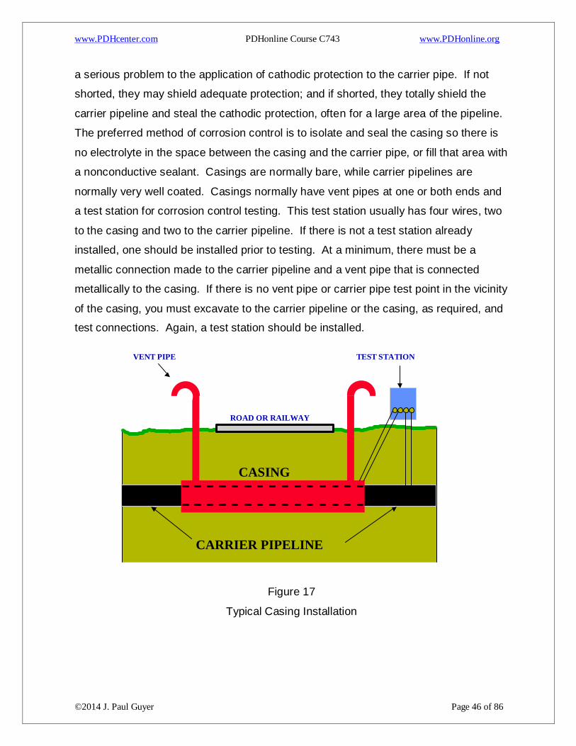
a serious problem to the application of cathodic protection to the carrier pipe. If not
shorted, they may shield adequate protection; and if shorted, they totally shield the
carrier pipeline and steal the cathodic protection, often for a large area of the pipeline.
The preferred method of corrosion control is to isolate and seal the casing so there is
no electrolyte in the space between the casing and the carrier pipe, or fill that area with
a nonconductive sealant. Casings are normally bare, while carrier pipelines are
normally very well coated. Casings normally have vent pipes at one or both ends and
a test station for corrosion control testing. This test station usually has four wires, two
to the casing and two to the carrier pipeline. If there is not a test station already
installed, one should be installed prior to testing. At a minimum, there must be a
metallic connection made to the carrier pipeline and a vent pipe that is connected
metallically to the casing. If there is no vent pipe or carrier pipe test point in the vicinity
of the casing, you must excavate to the carrier pipeline or the casing, as required, and
test connections. Again, a test station should be installed.
Figure 17
Typical Casing Installation
TEST STATION VENT PIPE
CASING
ROAD OR RAILWAY
CARRIER PIPELINE
www.PDHcenter.com PDHonline Course C743 www.PDHonline.org
©2014 J. Paul Guyer Page 47 of 86
CAUTION: Do not use an ohmmeter to measure resistance between the carrier
pipeline and the casing. If the isolation is good, current will flow through the meter and
damage could result. If that current does not damage the meter, the measurement
would not indicate a resistance value. The voltage would be interpreted by the meter
as coming from the internal battery instead of the external electrical circuit being
measured.
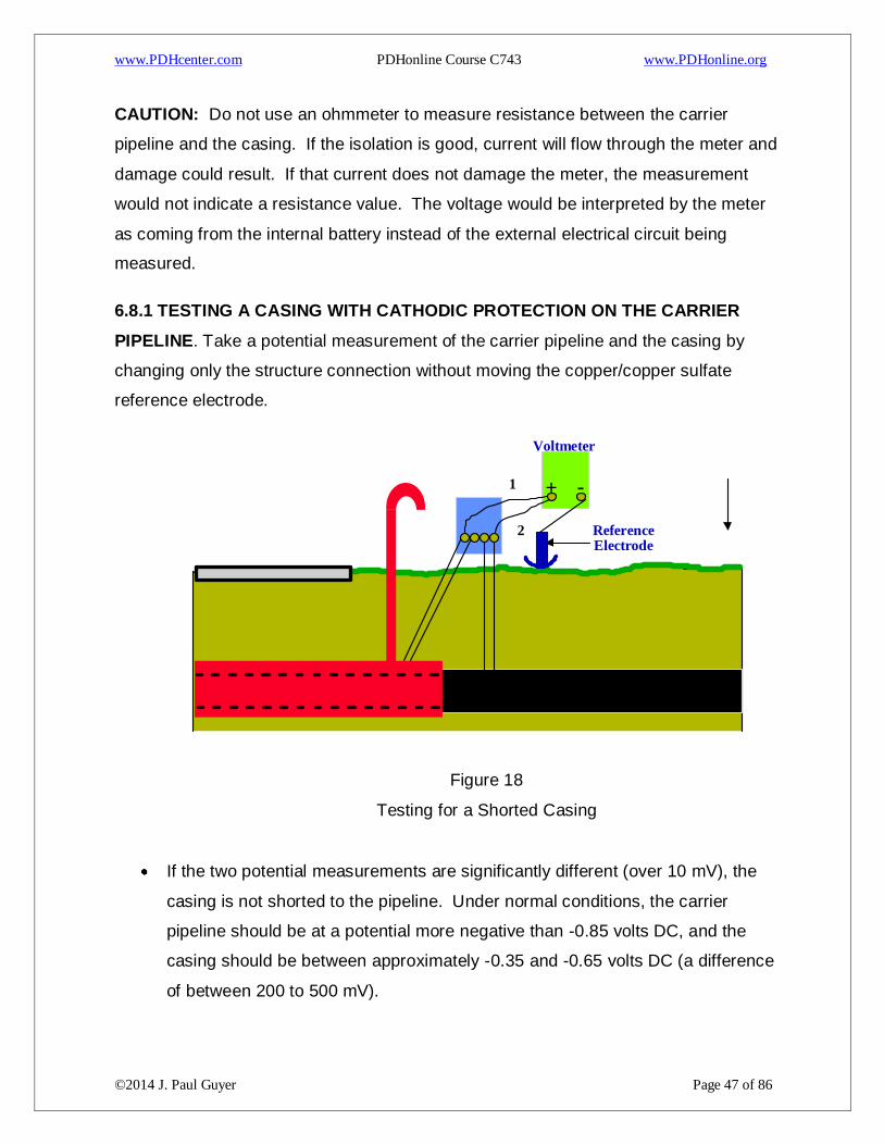
6.8.1 TESTING A CASING WITH CATHODIC PROTECTION ON THE CARRIER
PIPELINE. Take a potential measurement of the carrier pipeline and the casing by
changing only the structure connection without moving the copper/copper sulfate
reference electrode.
Figure 18
Testing for a Shorted Casing
If the two potential measurements are significantly different (over 10 mV), the
casing is not shorted to the pipeline. Under normal conditions, the carrier
pipeline should be at a potential more negative than -0.85 volts DC, and the
casing should be between approximately -0.35 and -0.65 volts DC (a difference
of between 200 to 500 mV).
Voltmeter
- + 1
2 Reference Electrode
www.PDHcenter.com PDHonline Course C743 www.PDHonline.org
©2014 J. Paul Guyer Page 48 of 86
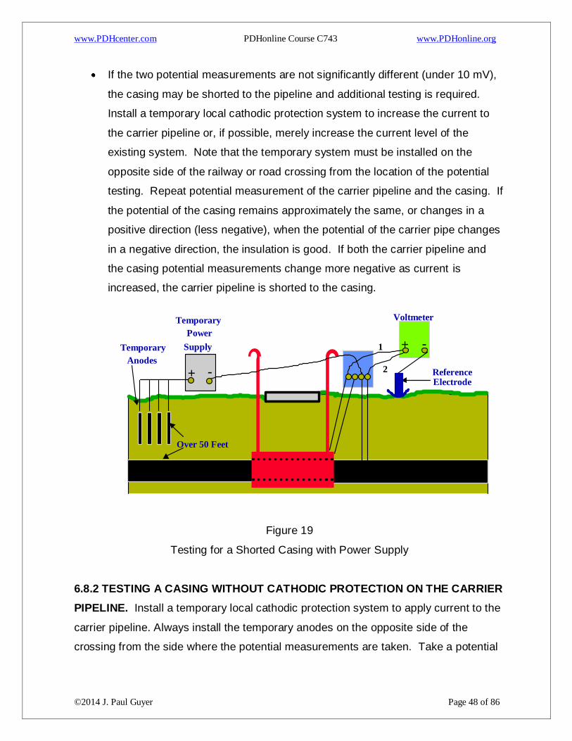
If the two potential measurements are not significantly different (under 10 mV),
the casing may be shorted to the pipeline and additional testing is required.
Install a temporary local cathodic protection system to increase the current to
the carrier pipeline or, if possible, merely increase the current level of the
existing system. Note that the temporary system must be installed on the
opposite side of the railway or road crossing from the location of the potential
testing. Repeat potential measurement of the carrier pipeline and the casing. If
the potential of the casing remains approximately the same, or changes in a
positive direction (less negative), when the potential of the carrier pipe changes
in a negative direction, the insulation is good. If both the carrier pipeline and
the casing potential measurements change more negative as current is
increased, the carrier pipeline is shorted to the casing.
Figure 19
Testing for a Shorted Casing with Power Supply
6.8.2 TESTING A CASING WITHOUT CATHODIC PROTECTION ON THE CARRIER
PIPELINE. Install a temporary local cathodic protection system to apply current to the
carrier pipeline. Always install the temporary anodes on the opposite side of the
crossing from the side where the potential measurements are taken. Take a potential
- +
Temporary
Supply
Power
Temporary
Anodes
Over 50 Feet
Voltmeter
- + 1
2 Reference Electrode
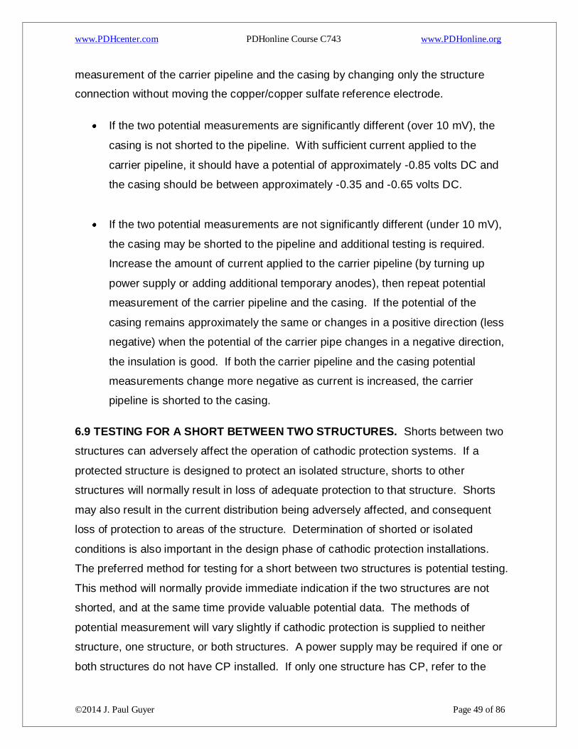
www.PDHcenter.com PDHonline Course C743 www.PDHonline.org
©2014 J. Paul Guyer Page 49 of 86
measurement of the carrier pipeline and the casing by changing only the structure
connection without moving the copper/copper sulfate reference electrode.
If the two potential measurements are significantly different (over 10 mV), the
casing is not shorted to the pipeline. With sufficient current applied to the
carrier pipeline, it should have a potential of approximately -0.85 volts DC and
the casing should be between approximately -0.35 and -0.65 volts DC.
If the two potential measurements are not significantly different (under 10 mV),
the casing may be shorted to the pipeline and additional testing is required.
Increase the amount of current applied to the carrier pipeline (by turning up
power supply or adding additional temporary anodes), then repeat potential
measurement of the carrier pipeline and the casing. If the potential of the
casing remains approximately the same or changes in a positive direction (less
negative) when the potential of the carrier pipe changes in a negative direction,
the insulation is good. If both the carrier pipeline and the casing potential
measurements change more negative as current is increased, the carrier
pipeline is shorted to the casing.
6.9 TESTING FOR A SHORT BETWEEN TWO STRUCTURES. Shorts between two
structures can adversely affect the operation of cathodic protection systems. If a
protected structure is designed to protect an isolated structure, shorts to other
structures will normally result in loss of adequate protection to that structure. Shorts
may also result in the current distribution being adversely affected, and consequent
loss of protection to areas of the structure. Determination of shorted or isolated
conditions is also important in the design phase of cathodic protection installations.
The preferred method for testing for a short between two structures is potential testing.
This method will normally provide immediate indication if the two structures are not
shorted, and at the same time provide valuable potential data. The methods of
potential measurement will vary slightly if cathodic protection is supplied to neither
structure, one structure, or both structures. A power supply may be required if one or
both structures do not have CP installed. If only one structure has CP, refer to the
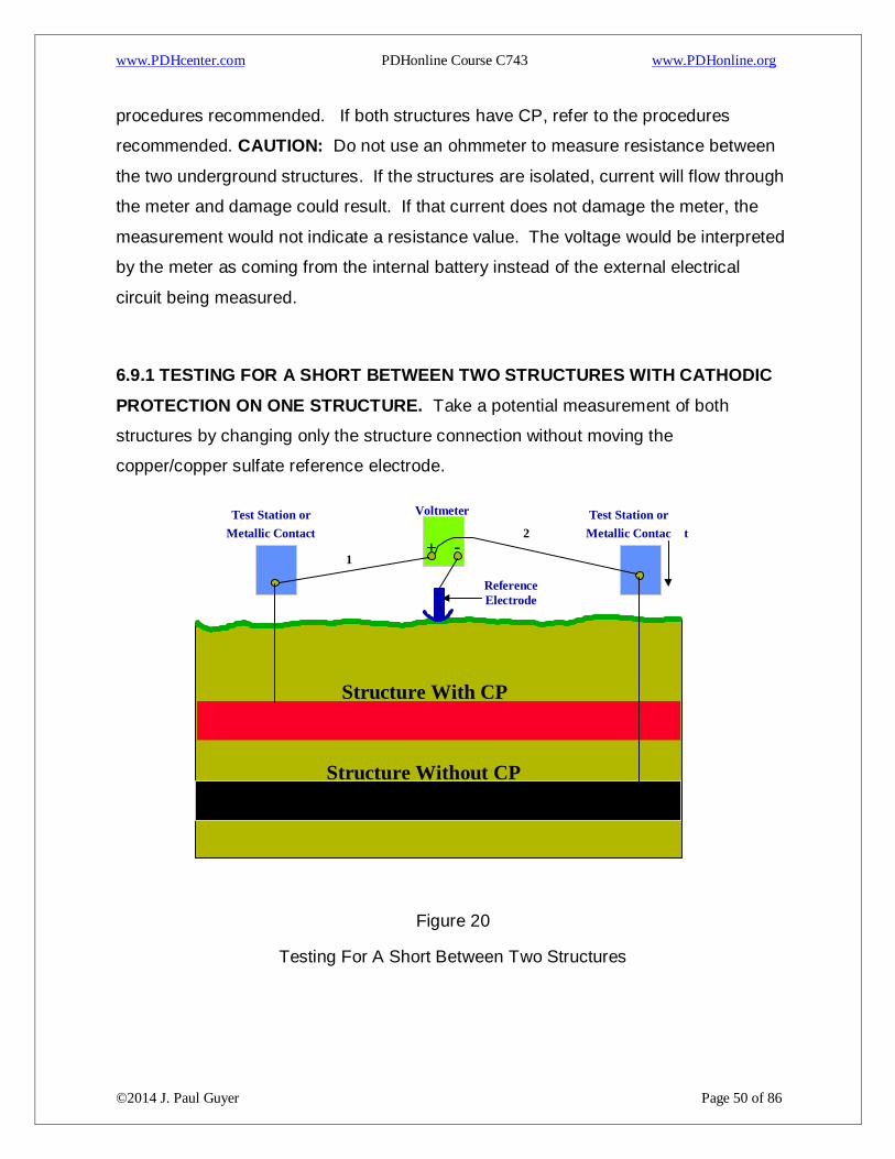
www.PDHcenter.com PDHonline Course C743 www.PDHonline.org
©2014 J. Paul Guyer Page 50 of 86
procedures recommended. If both structures have CP, refer to the procedures
recommended. CAUTION: Do not use an ohmmeter to measure resistance between
the two underground structures. If the structures are isolated, current will flow through
the meter and damage could result. If that current does not damage the meter, the
measurement would not indicate a resistance value. The voltage would be interpreted
by the meter as coming from the internal battery instead of the external electrical
circuit being measured.
6.9.1 TESTING FOR A SHORT BETWEEN TWO STRUCTURES WITH CATHODIC
PROTECTION ON ONE STRUCTURE. Take a potential measurement of both
structures by changing only the structure connection without moving the
copper/copper sulfate reference electrode.
Figure 20
Testing For A Short Between Two Structures
Voltmeter
- + 1
2
Reference Electrode
Test Station or Metallic Contact
Test Station or Metallic Contac t
Structure With CP
Structure Without CP
www.PDHcenter.com PDHonline Course C743 www.PDHonline.org
©2014 J. Paul Guyer Page 51 of 86
If the two potential measurements are significantly different (over 10 mV), the
two structures are not metallically shorted together. Under normal conditions,
the structure with cathodic protection should be at a potential more negative
than -0.85 volts DC and the steel structure without cathodic protection should
be between approximately -0.35 volts DC and -0.65 volts DC (a difference of
between 200 to 500 mV). If the other structure is copper or steel in concrete
under normal conditions, it should have a potential between approximately -
0.20 volts DC and -0.30 volts DC.
If the two potential measurements are not significantly different (under 10 mV),
the two structures may be shorted, and additional testing is required. Install a
temporary local cathodic protection system to increase the current to the carrier
pipeline or, if possible, merely increase the current level of the existing system.
Note that the temporary system should be installed where the current should
distribute to just one structure. Repeat the potential measurement of both
structures. If the potential of the unprotected structure remains approximately
the same or changes in a positive direction (less negative), when the potential
of the protected structure changes in a negative direction, they are not shorted.
If both potential measurements change more negative as current is increased,
the two structures are shorted together.
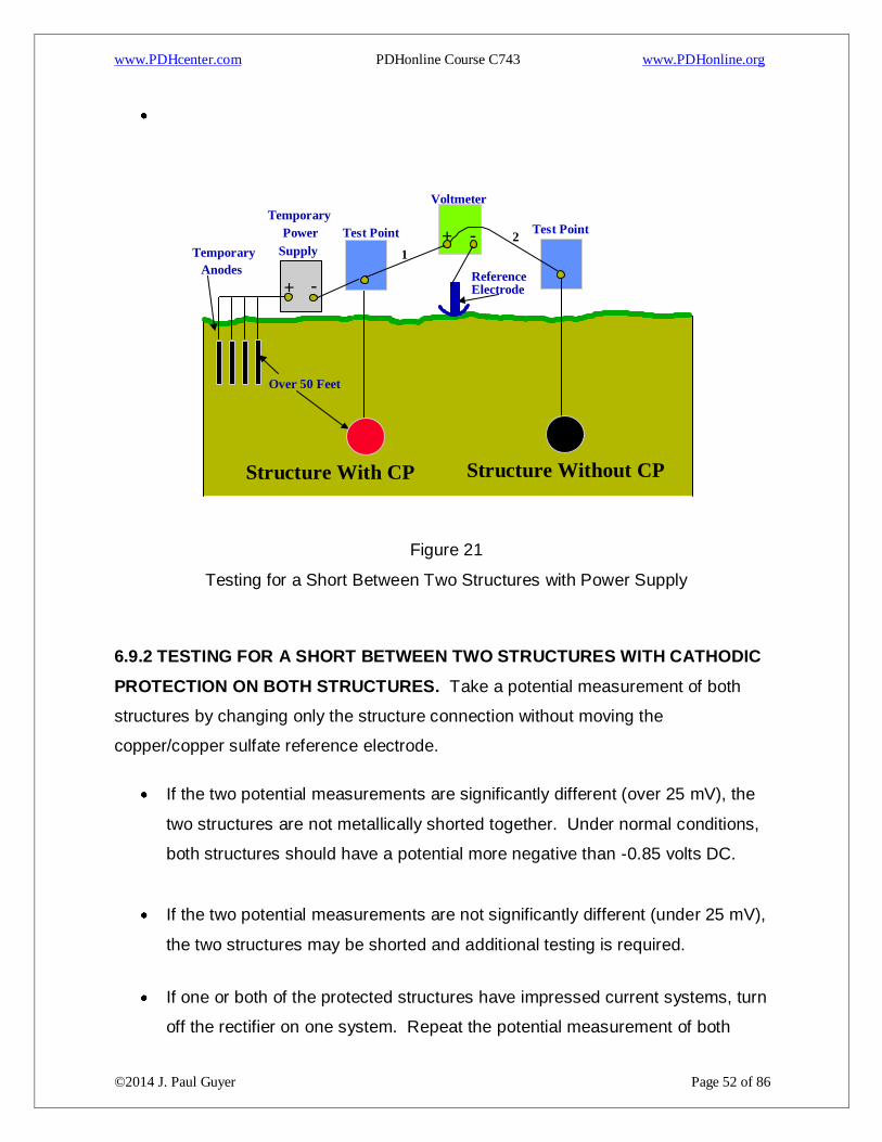
www.PDHcenter.com PDHonline Course C743 www.PDHonline.org
©2014 J. Paul Guyer Page 52 of 86
Figure 21
Testing for a Short Between Two Structures with Power Supply
6.9.2 TESTING FOR A SHORT BETWEEN TWO STRUCTURES WITH CATHODIC
PROTECTION ON BOTH STRUCTURES. Take a potential measurement of both
structures by changing only the structure connection without moving the
copper/copper sulfate reference electrode.
If the two potential measurements are significantly different (over 25 mV), the
two structures are not metallically shorted together. Under normal conditions,
both structures should have a potential more negative than -0.85 volts DC.
If the two potential measurements are not significantly different (under 25 mV),
the two structures may be shorted and additional testing is required.
If one or both of the protected structures have impressed current systems, turn
off the rectifier on one system. Repeat the potential measurement of both
- +
Temporary
Supply Power
Temporary Anodes
Over 50 Feet
Voltmeter
- + 1
2
Reference Electrode
Test Point Test Point
Structure With CP Structure Without CP
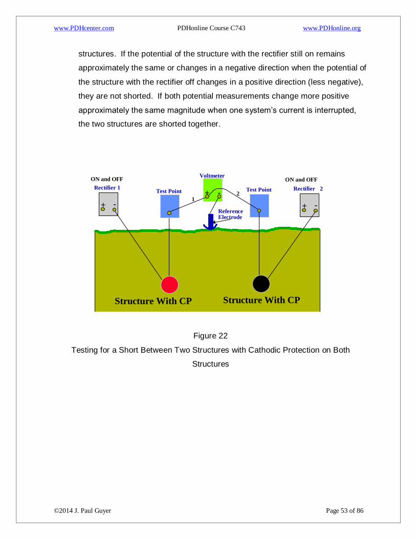
www.PDHcenter.com PDHonline Course C743 www.PDHonline.org
©2014 J. Paul Guyer Page 53 of 86
structures. If the potential of the structure with the rectifier still on remains
approximately the same or changes in a negative direction when the potential of
the structure with the rectifier off changes in a positive direction (less negative),
they are not shorted. If both potential measurements change more positive
approximately the same magnitude when one system’s current is interrupted,
the two structures are shorted together.
Figure 22
Testing for a Short Between Two Structures with Cathodic Protection on Both
Structures
- +
Voltmeter
- + 1
2
Reference Electrode
Test Point Test Point
Structure With CP Structure With CP
- +
Rectifier 1 Rectifier 2
ON and OFF ON and OFF
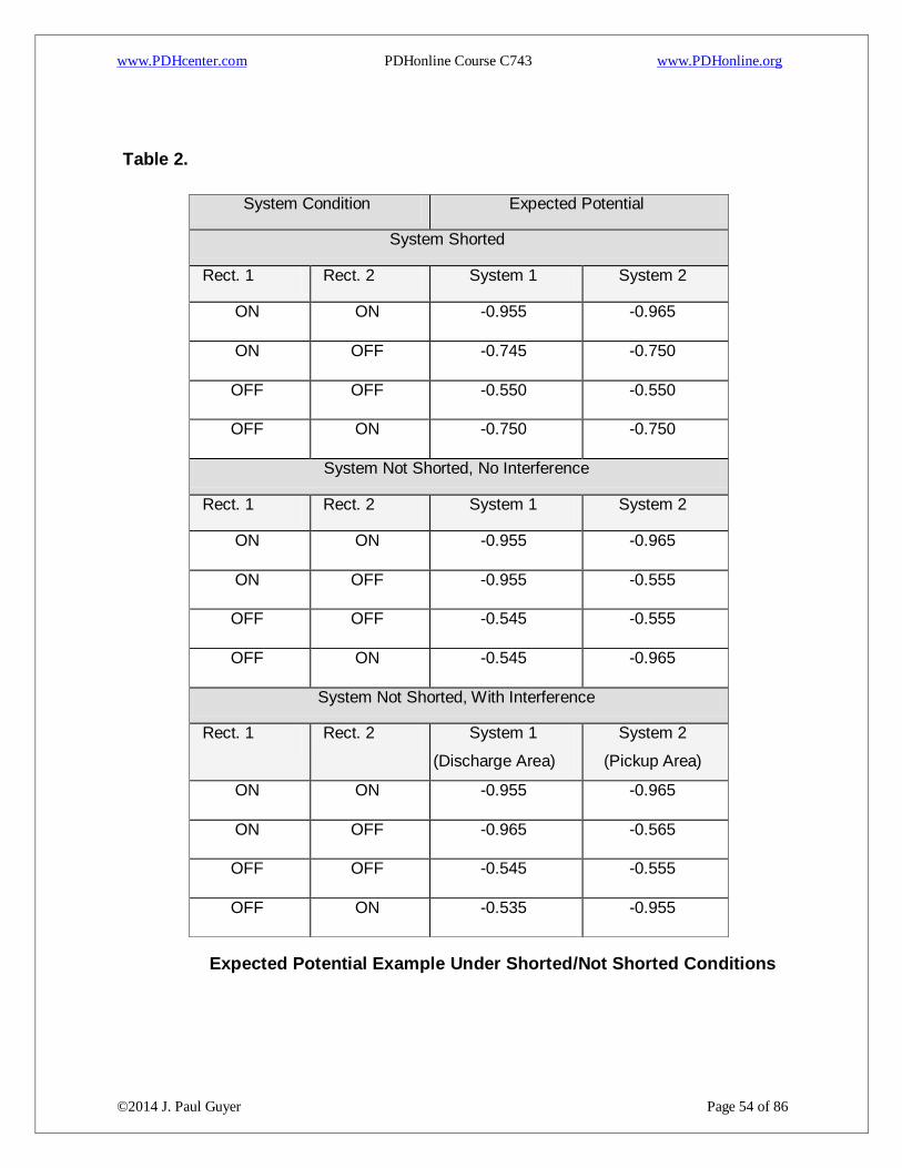
www.PDHcenter.com PDHonline Course C743 www.PDHonline.org
©2014 J. Paul Guyer Page 54 of 86
Table 2.
Expected Potential Example Under Shorted/Not Shorted Conditions
System Condition Expected Potential
System Shorted
Rect. 1 Rect. 2 System 1 System 2
ON ON -0.955 -0.965
ON OFF -0.745 -0.750
OFF OFF -0.550 -0.550
OFF ON -0.750 -0.750
System Not Shorted, No Interference
Rect. 1 Rect. 2 System 1 System 2
ON ON -0.955 -0.965
ON OFF -0.955 -0.555
OFF OFF -0.545 -0.555
OFF ON -0.545 -0.965
System Not Shorted, With Interference
Rect. 1 Rect. 2 System 1
(Discharge Area)
System 2
(Pickup Area)
ON ON -0.955 -0.965
ON OFF -0.965 -0.565
OFF OFF -0.545 -0.555
OFF ON -0.535 -0.955

www.PDHcenter.com PDHonline Course C743 www.PDHonline.org
©2014 J. Paul Guyer Page 55 of 86
R
If both systems have impressed current systems and a clear indication of the shorted
condition has still not been identified, repeat previous test procedure leaving the first
system’s rectifier on and interrupting the second system’s rectifier. If the potential of
the structure with the rectifier still on remains approximately the same or changes in a
negative direction when the potential of the structure with the rectifier off changes in a
positive direction (less negative), they are not shorted. If both potential measurements
change more positive approximately the same magnitude (less negative) when one
system’s current is interrupted, the two structures are shorted together. If both systems
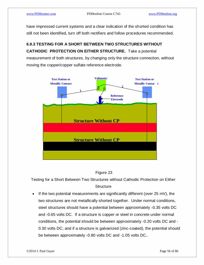
www.PDHcenter.com PDHonline Course C743 www.PDHonline.org
©2014 J. Paul Guyer Page 56 of 86
have impressed current systems and a clear indication of the shorted condition has
still not been identified, turn off both rectifiers and follow procedures recommended.
6.9.3 TESTING FOR A SHORT BETWEEN TWO STRUCTURES WITHOUT
CATHODIC PROTECTION ON EITHER STRUCTURE. Take a potential
measurement of both structures, by changing only the structure connection, without
moving the copper/copper sulfate reference electrode.
Figure 23
Testing for a Short Between Two Structures without Cathodic Protection on Either
Structure
If the two potential measurements are significantly different (over 25 mV), the
two structures are not metallically shorted together. Under normal conditions,
steel structures should have a potential between approximately -0.35 volts DC
and -0.65 volts DC. If a structure is copper or steel in concrete under normal
conditions, the potential should be between approximately -0.20 volts DC and -
0.30 volts DC; and if a structure is galvanized (zinc-coated), the potential should
be between approximately -0.80 volts DC and -1.05 volts DC..
Voltmeter
- + 1
2
Reference Electrode
Test Station or Metallic Contact
Test Station or Metallic Contac t
Structure Without CP
Structure Without CP
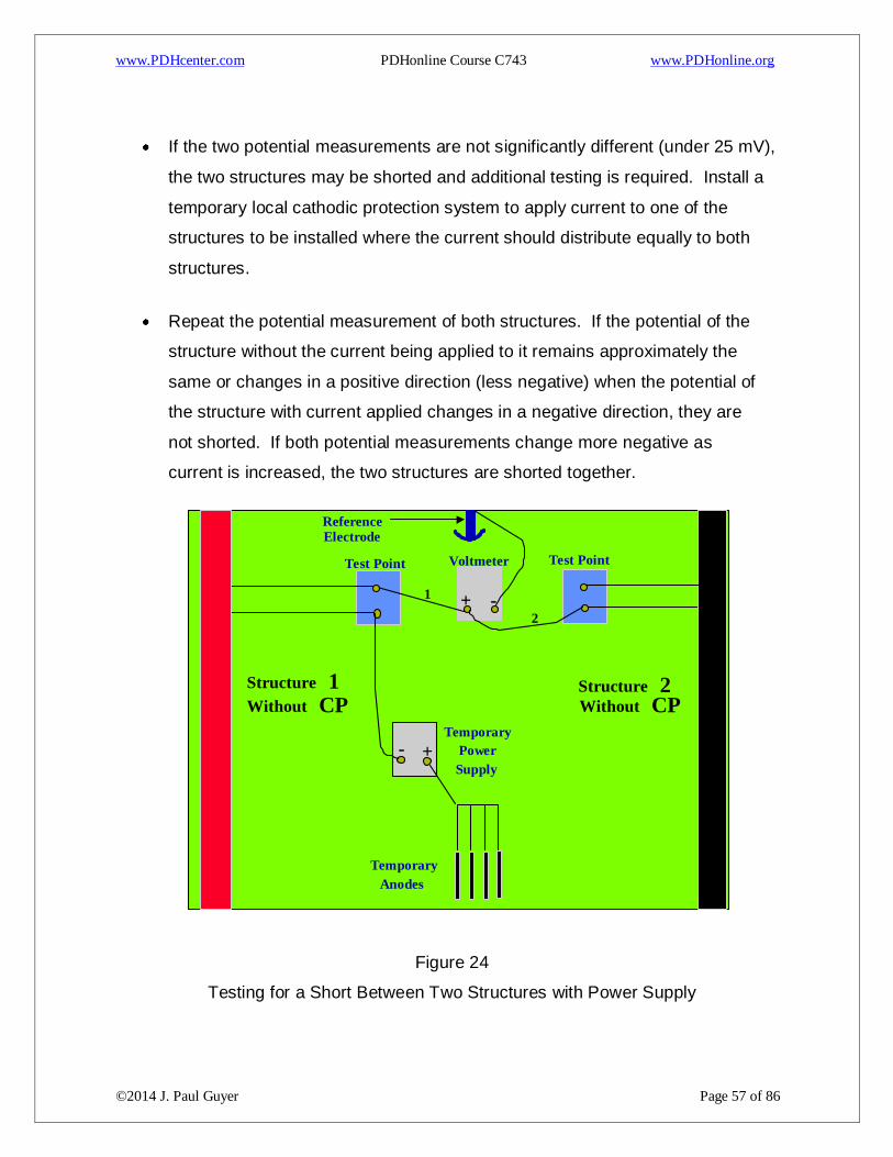
www.PDHcenter.com PDHonline Course C743 www.PDHonline.org
©2014 J. Paul Guyer Page 57 of 86
If the two potential measurements are not significantly different (under 25 mV),
the two structures may be shorted and additional testing is required. Install a
temporary local cathodic protection system to apply current to one of the
structures to be installed where the current should distribute equally to both
structures.
Repeat the potential measurement of both structures. If the potential of the
structure without the current being applied to it remains approximately the
same or changes in a positive direction (less negative) when the potential of
the structure with current applied changes in a negative direction, they are
not shorted. If both potential measurements change more negative as
current is increased, the two structures are shorted together.
Figure 24
Testing for a Short Between Two Structures with Power Supply
Temporary Anodes
Voltmeter
- + 1
2
Reference Electrode
- +
Temporary
Supply Power
Test Point Test Point
Structure 1 Without CP
Structure 2 Without CP
www.PDHcenter.com PDHonline Course C743 www.PDHonline.org
©2014 J. Paul Guyer Page 58 of 86
6.10 CURRENT REQUIREMENT TESTING PROCEDURES. Current requirement
testing is conducted when planning a cathodic protection system installation to
determine the type and size of the system required. If the system design requires
isolation of the structure to be protected, that isolation must be accomplished prior to
the current requirement test. The current requirement for a non-isolated structure
does not give any indication of what the current requirement would be if the structure
were isolated. Temporary systems are used to determine the effect of current applied
on the potential of the structure being tested. Actual protection need not be
accomplished to estimate the amount of current required. Portable rectifiers should be
used together with temporary anodes (usually ground rods) or existing metallic
structures to impress a test current to the structure. Vehicle batteries can be used, as
well as spare rectifiers, DC generators, DC welding units, or rectifiers fro m other
systems can be temporarily removed for use.
6.10.1 TEMPORARY LOCAL CATHODIC PROTECTION SYSTEMS. Temporary
local cathodic protection systems should be located in areas where the intended
installation is to be located, if known. If not known, they should be located as remote
as possible from the structure to be protected, without any foreign structures in the
area of the temporary anode bed, and without any foreign structure between the
temporary anode bed and the structure to be protected.
WARNING: Do not use any metallic structure for a temporary anode that is shorted to
the structure being tested. This will result in very large current surges that can cause
injury to personnel and damage to equipment. For Navy projects, when conducting
work on or near circuits energized lines or parts of equipment operating at or above
50V, utilize work practices identified in OPNAV P-45-116-98.
6.10.2 EXISTING METALLIC STRUCTURES. Existing metallic structures, such as
metal fences, culverts, abandoned pipelines, or abandoned wells can be used as
temporary anodes or to supplement installed temporary anodes. If any existing
structure is to be used, it should first be tested to see if that structure is shorted to the
structure to be tested. The area of the temporary installation should be well scouted to
www.PDHcenter.com PDHonline Course C743 www.PDHonline.org
©2014 J. Paul Guyer Page 59 of 86
determine if any possible temporary anodes exist or if any foreign structure is in the
area. Do not use pipelines or tanks for temporary anodes that would be adversely
affected if leaks occurred.
6.10.3 TEMPORARY ANODES. The number of temporary anodes required depends
on the available voltage source, the amount of current desired, and the resistivity of
the soil. If the number of anodes is doubled, the amount of current is approximately
doubled. If the soil resistivity is doubled, the current is cut in half. In very low
resistivity soil, two or three anodes may be sufficient, and in very high resistivity soil, a
high number of temporary anodes may be required. The amount of current desired
depends basically on the quality of the coating on the structure being tested. Very
well-coated structures will exhibit a noticeable potential change with a small amount of
current (1 or 2 amps), while poorly-coated structures will not exhibit a noticeable
potential change except with a large amount of current (10 to 20 amps). If the voltage
is doubled, the current is doubled. Consequently, if the voltage source is low, more
temporary anodes will be required, if the voltage source is very high, only a few
temporary anodes will be required.
6.10.4 INSTALLATION OF TEMPORARY ANODE SYSTEM. The installation of a
temporary anode system is often required to perform current requirement testing.
Normally copper ground rods are used. Any metallic ground rod can be used as well
as any metallic pipe or conduit. Streams, ponds, rivers, lakes, bays, oceans, or other
standing water in the area of the temporary anode location make an ideal location for
obtaining a low resistance-to-earth anode bed. In these wet locations, the ground rods
can be simply laid in the water. Normally ground rods are cut in half to make 4- to 5-
foot sections. These ground rods (or metallic pipe or conduit), are sharpened and
driven into the ground until approximately 0.3 meters (one foot) are above the ground
level. These rods should be installed approximately 4.5 to 6 meters (15 to 20 feet)
apart to lower the resistance to earth. In high resistivity areas, when higher test
current is required, water sprinklers can be used over a period of time to lower the
resistance. In extreme cases, an excavation can be made, then small diameter steel
pipe can be pushed into the earth with a backhoe or bulldozer. This method can also
www.PDHcenter.com PDHonline Course C743 www.PDHonline.org
©2014 J. Paul Guyer Page 60 of 86
be used to simulate a deeper installation. It is possible to install 9 to 18 meters (30 to
60 feet) in this manner if there are no rock formations.
CAUTION: Do not connect the structure being tested to the positive terminal of the
power source. Severe corrosion of the structure may result.
6.10.5 CONNECTIONS. The temporary anodes all must be connected to the power
source positive terminal. The structure being tested must be connected to the
negative terminal. For physical strength and low resistance, #6 AWG copper cable or
larger must be used and #2 AWG or greater is desired, especially if long runs in either
the structure or anode cable are needed. Connections can be made with pipe clamps,
test clamps of sufficient size, split bolts, and exothermic welding. All wire and
connections must be made to accommodate the voltage and current required for the
testing. The normal portable rectifier is 60 volts at 30 amps or 30 volts at 60 amps.
Other rectifiers may be over 180 volts or 100 amps.
6.10.6 BEFORE APPLYING POWER. Before any power is applied, it is essential to
obtain the as-found potential data of the structure. The native potential must be tested
for all locations to be tested during the current requirement test, to obtain the potential
shift accomplished by the test current.
6.10.7 APPLYING POWER. Beginning at a low voltage setting, turn power on, ensure
the potential shift of the structure is in the negative direction. Gradually increase
voltage and current to desired output, while periodically checking potential to ensure a
corresponding negative shift as current is increased. If maximum voltage is reached
and more current is still required, turn system off and supplement the temporary anode
bed.
6.10.8 SUFFICIENT CURRENT. Sufficient current is applied when a substantial
section of the structure to be tested has achieved a noticeable potential shift or when
full protection is achieved. If full protection is achieved, the current requirement is the
same as the test current. If full protection is not achieved, further calculations are
required.
www.PDHcenter.com PDHonline Course C743 www.PDHonline.org
©2014 J. Paul Guyer Page 61 of 86
6.10.9 CALCULATING CURRENT REQUIREMENTS. Once the potential shift is
ascertained, and the current to get that shift is known, the current requirement can be
calculated. If the current is doubled, the potential shift is doubled. Current distribution
should be considered: If good current distribution is achieved, a simple mathematical
formula will produce the current requirement. If proper current distribution is not
achieved, it must be designed into the system. If the design will call for a deeper
anode bed, current requirement can be estimated by calculations. If the design is for
surface beds, additional cathodic protection systems should be considered and further
current requirement testing for additional locations conducted.
6.10.10 MORE THAN ONE ANODE BED. If a current requirement test includes more
than one anode bed location; all current sources should be interrupted simultaneously
to measure the potential shift of the structure. The total current requirement is found
by adding the current from all power sources together. Always consider proper current
distribution and estimate the required current requirement for each individual system.
6.10.11 COMPLETION OF TESTING. Upon completion of testing, turn all power
sources off, disconnect all cables, and remove temporary anodes. For ease of
removal of ground rods or small diameter pipes and conduit, use three flat metal bars
as shown in Figure 25.
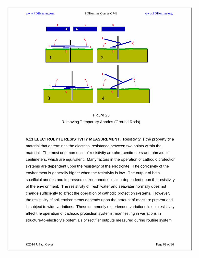
www.PDHcenter.com PDHonline Course C743 www.PDHonline.org
©2014 J. Paul Guyer Page 62 of 86
Figure 25
Removing Temporary Anodes (Ground Rods)
6.11 ELECTROLYTE RESISTIVITY MEASUREMENT. Resistivity is the property of a
material that determines the electrical resistance between two points within the
material. The most common units of resistivity are ohm-centimeters and ohm/cubic
centimeters, which are equivalent. Many factors in the operation of cathodic protection
systems are dependent upon the resistivity of the electrolyte. The corrosivity of the
environment is generally higher when the resistivity is low. The output of both
sacrificial anodes and impressed current anodes is also dependent upon the resistivity
of the environment. The resistivity of fresh water and seawater normally does not
change sufficiently to affect the operation of cathodic protection systems. However,
the resistivity of soil environments depends upon the amount of moisture present and
is subject to wide variations. These commonly experienced variations in soil resistivity
affect the operation of cathodic protection systems, manifesting in variations in
structure-to-electrolyte potentials or rectifier outputs measured during routine system
1 2 3
3
1 2
2 1
3
1 2
3 4
1 2
2
1
3 3
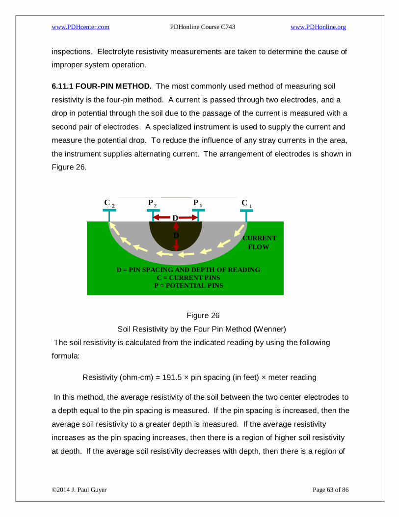
www.PDHcenter.com PDHonline Course C743 www.PDHonline.org
©2014 J. Paul Guyer Page 63 of 86
inspections. Electrolyte resistivity measurements are taken to determine the cause of
improper system operation.
6.11.1 FOUR-PIN METHOD. The most commonly used method of measuring soil
resistivity is the four-pin method. A current is passed through two electrodes, and a
drop in potential through the soil due to the passage of the current is measured with a
second pair of electrodes. A specialized instrument is used to supply the current and
measure the potential drop. To reduce the influence of any stray currents in the area,
the instrument supplies alternating current. The arrangement of electrodes is shown in
Figure 26.
Figure 26
Soil Resistivity by the Four Pin Method (Wenner)
The soil resistivity is calculated from the indicated reading by using the following
formula:
Resistivity (ohm-cm) = 191.5 × pin spacing (in feet) × meter reading
In this method, the average resistivity of the soil between the two center electrodes to
a depth equal to the pin spacing is measured. If the pin spacing is increased, then the
average soil resistivity to a greater depth is measured. If the average resistivity
increases as the pin spacing increases, then there is a region of higher soil resistivity
at depth. If the average soil resistivity decreases with depth, then there is a region of
CURRENT
FLOW
D = PIN SPACING AND DEPTH OF READING C = CURRENT PINS
P = POTENTIAL PINS
D
D
C C P P 2 2 1 1

www.PDHcenter.com PDHonline Course C743 www.PDHonline.org
©2014 J. Paul Guyer Page 64 of 86
lower soil resistivity at depth. For multipliers for common distances and distances for
even multipliers, see Table 2.
Table 3. Four-Pin Soil Resistivity Measurement Reading Multipliers
Common Distances Even Multipliers
Distance
Between Rods
Reading
Multiplier
Distance
Between Rods
Reading
Multiplier
2’6” 479 2’7” 500
5’ 958 5’3” 1000
7’6” 1,436 7’10” 1,500
10’ 1,915 10’5” 2,000
12’6” 2,394 13’1” 2,500
15’ 2,872 15’8” 3,000
20’ 3,830 20’11” 4,000
30’ 5,745 31’4” 6,000
6.11.2 TWO-PIN METHOD. In the two-pin method of soil resistivity measurement, the
potential drop is measured between the same pair of electrodes used to supply the
current. The equipment used to make this type of measurement is often called the
“Shepard’s Canes,” after its inventor. As shown in Figure 27, the probes are placed
0.3 meters (one foot) apart. If the soil is too hard for the probes to penetrate, the
reading is taken at the bottom of two augured holes. The instrument is calibrated for a
probe spacing of one foot and gives a reading directly in ohm-cm. Although this
method is less accurate than the four-pin method and measures the resistivity of the
soil only near the surface, it is often used for preliminary surveys, as it is quicker than
the four-pin method.
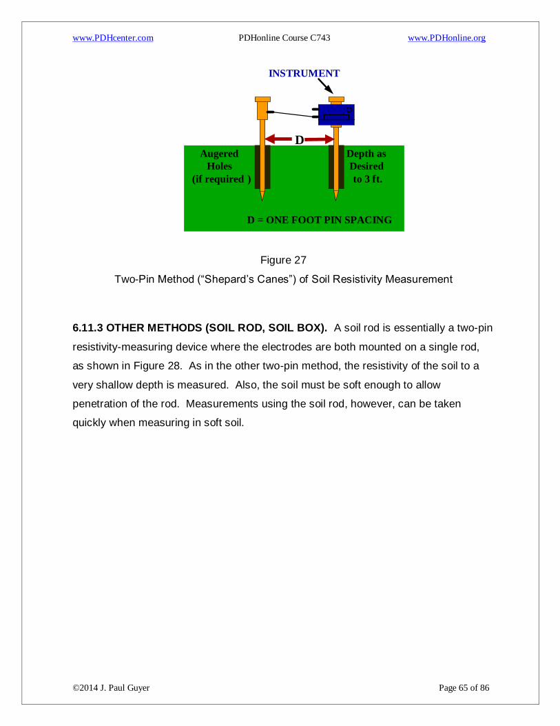
www.PDHcenter.com PDHonline Course C743 www.PDHonline.org
©2014 J. Paul Guyer Page 65 of 86
Figure 27
Two-Pin Method (“Shepard’s Canes”) of Soil Resistivity Measurement
6.11.3 OTHER METHODS (SOIL ROD, SOIL BOX). A soil rod is essentially a two-pin
resistivity-measuring device where the electrodes are both mounted on a single rod,
as shown in Figure 28. As in the other two-pin method, the resistivity of the soil to a
very shallow depth is measured. Also, the soil must be soft enough to allow
penetration of the rod. Measurements using the soil rod, however, can be taken
quickly when measuring in soft soil.
INSTRUMENT
D = ONE FOOT PIN SPACING
D
Depth as
Desired
to 3 ft.
Augered
Holes
( if required )
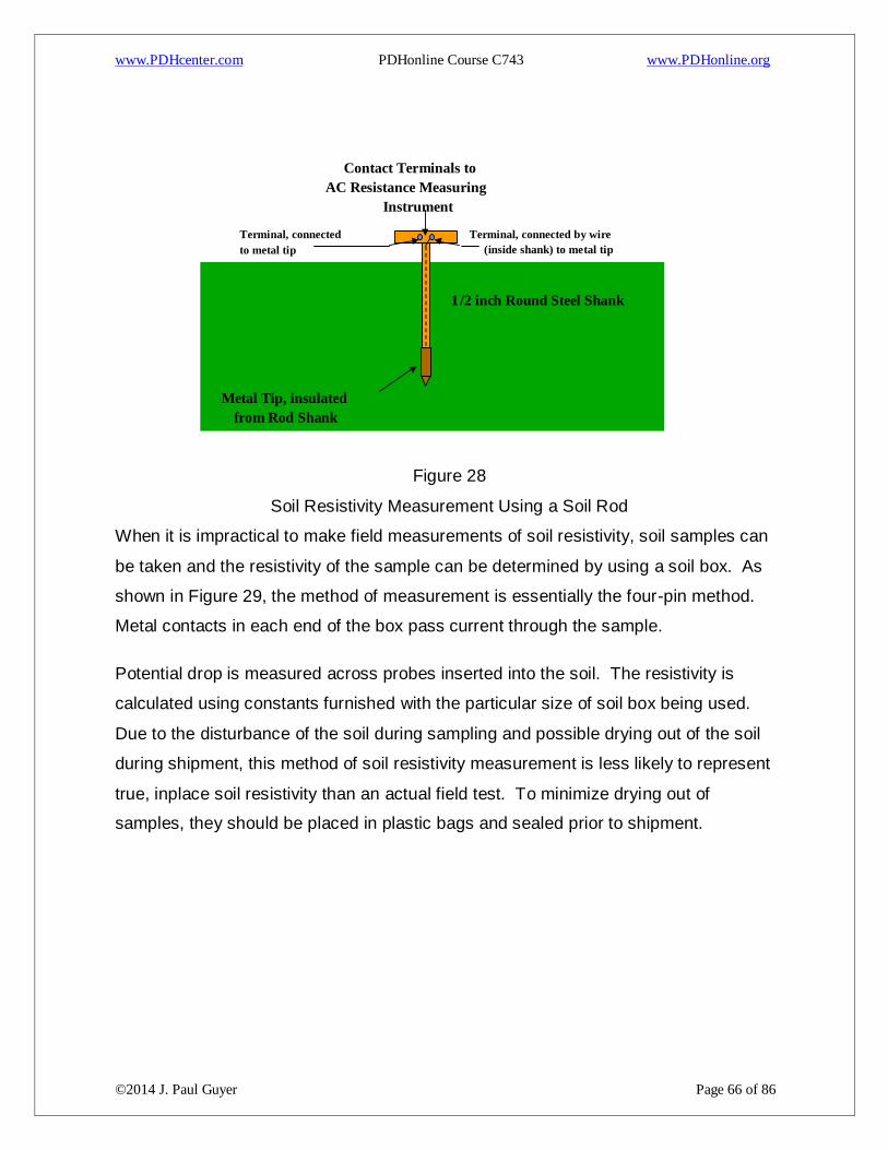
www.PDHcenter.com PDHonline Course C743 www.PDHonline.org
©2014 J. Paul Guyer Page 66 of 86
Figure 28
Soil Resistivity Measurement Using a Soil Rod
When it is impractical to make field measurements of soil resistivity, soil samples can
be taken and the resistivity of the sample can be determined by using a soil box. As
shown in Figure 29, the method of measurement is essentially the four-pin method.
Metal contacts in each end of the box pass current through the sample.
Potential drop is measured across probes inserted into the soil. The resistivity is
calculated using constants furnished with the particular size of soil box being used.
Due to the disturbance of the soil during sampling and possible drying out of the soil
during shipment, this method of soil resistivity measurement is less likely to represent
true, inplace soil resistivity than an actual field test. To minimize drying out of
samples, they should be placed in plastic bags and sealed prior to shipment.
Metal Tip, insulated from Rod Shank
Terminal, connected by wire inside shank) to metal tip (
Contact Terminals to AC Resistance Measuring
Instrument
Terminal, connected to metal tip
1 /2 inch Round Steel Shank
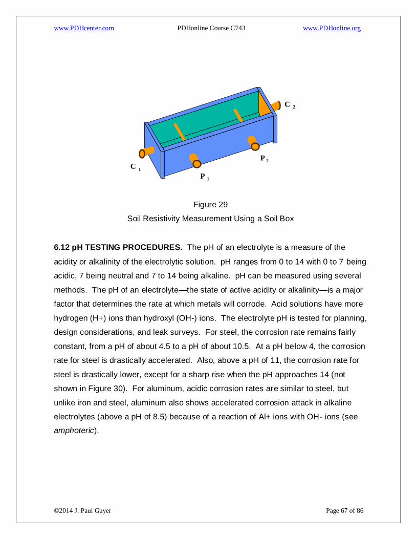
www.PDHcenter.com PDHonline Course C743 www.PDHonline.org
©2014 J. Paul Guyer Page 67 of 86
Figure 29
Soil Resistivity Measurement Using a Soil Box
6.12 pH TESTING PROCEDURES. The pH of an electrolyte is a measure of the
acidity or alkalinity of the electrolytic solution. pH ranges from 0 to 14 with 0 to 7 being
acidic, 7 being neutral and 7 to 14 being alkaline. pH can be measured using several
methods. The pH of an electrolyte—the state of active acidity or alkalinity—is a major
factor that determines the rate at which metals will corrode. Acid solutions have more
hydrogen (H+) ions than hydroxyl (OH-) ions. The electrolyte pH is tested for planning,
design considerations, and leak surveys. For steel, the corrosion rate remains fairly
constant, from a pH of about 4.5 to a pH of about 10.5. At a pH below 4, the corrosion
rate for steel is drastically accelerated. Also, above a pH of 11, the corrosion rate for
steel is drastically lower, except for a sharp rise when the pH approaches 14 (not
shown in Figure 30). For aluminum, acidic corrosion rates are similar to steel, but
unlike iron and steel, aluminum also shows accelerated corrosion attack in alkaline
electrolytes (above a pH of 8.5) because of a reaction of Al+ ions with OH- ions (see
amphoteric).
C 2
P 2
P 1
C 1
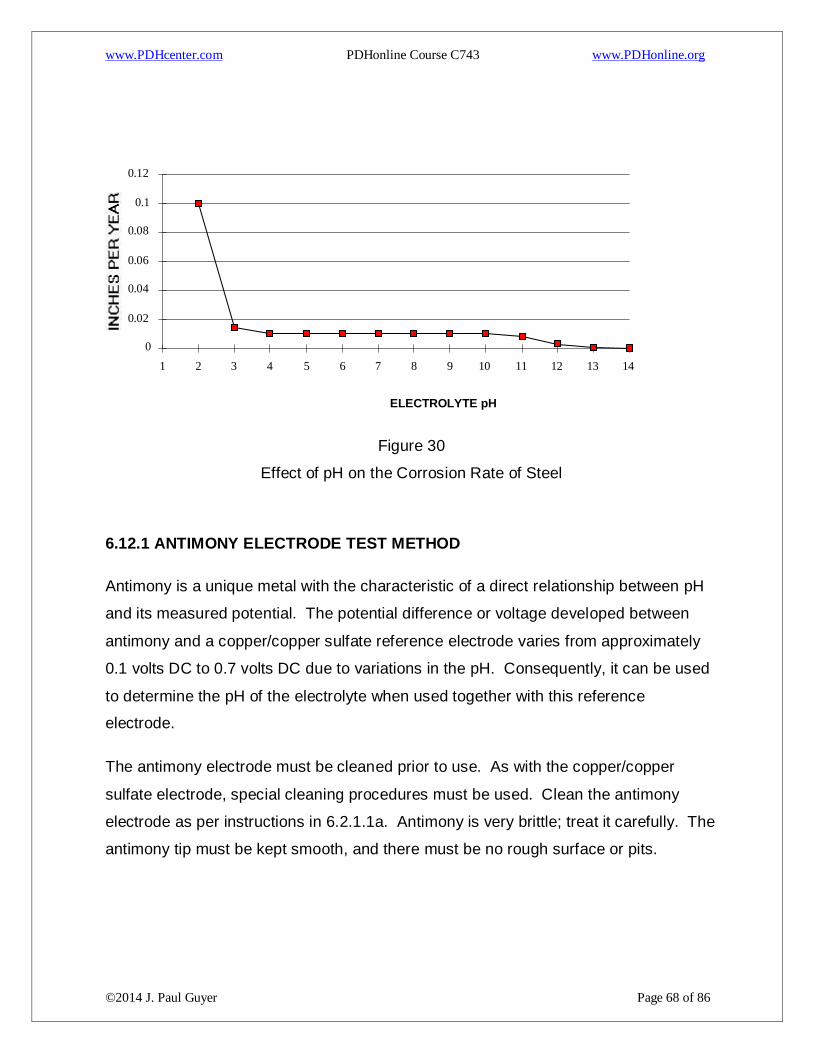
www.PDHcenter.com PDHonline Course C743 www.PDHonline.org
©2014 J. Paul Guyer Page 68 of 86
ELECTROLYTE pH
Figure 30
Effect of pH on the Corrosion Rate of Steel
6.12.1 ANTIMONY ELECTRODE TEST METHOD
Antimony is a unique metal with the characteristic of a direct relationship between pH
and its measured potential. The potential difference or voltage developed between
antimony and a copper/copper sulfate reference electrode varies from approximately
0.1 volts DC to 0.7 volts DC due to variations in the pH. Consequently, it can be used
to determine the pH of the electrolyte when used together with this reference
electrode.
The antimony electrode must be cleaned prior to use. As with the copper/copper
sulfate electrode, special cleaning procedures must be used. Clean the antimony
electrode as per instructions in 6.2.1.1a. Antimony is very brittle; treat it carefully. The
antimony tip must be kept smooth, and there must be no rough surface or pits.
0
0.02
0.04
0.06
0.08
0.1
0.12
1 2 3 4 5 6 7 8 9 10 11 12 13 14
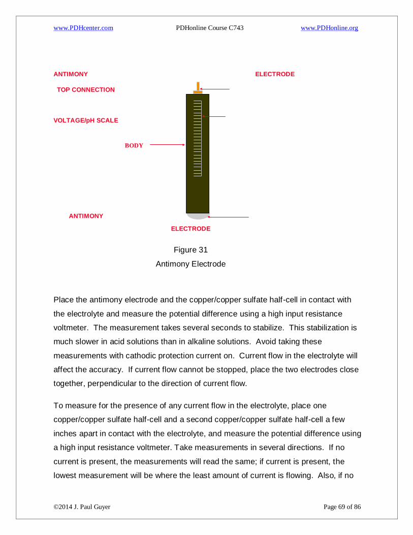
www.PDHcenter.com PDHonline Course C743 www.PDHonline.org
©2014 J. Paul Guyer Page 69 of 86
ANTIMONY ELECTRODE
TOP CONNECTION
VOLTAGE/pH SCALE
ANTIMONY
ELECTRODE
Figure 31
Antimony Electrode
Place the antimony electrode and the copper/copper sulfate half-cell in contact with
the electrolyte and measure the potential difference using a high input resistance
voltmeter. The measurement takes several seconds to stabilize. This stabilization is
much slower in acid solutions than in alkaline solutions. Avoid taking these
measurements with cathodic protection current on. Current flow in the electrolyte will
affect the accuracy. If current flow cannot be stopped, place the two electrodes close
together, perpendicular to the direction of current flow.
To measure for the presence of any current flow in the electrolyte, place one
copper/copper sulfate half-cell and a second copper/copper sulfate half-cell a few
inches apart in contact with the electrolyte, and measure the potential difference using
a high input resistance voltmeter. Take measurements in several directions. If no
current is present, the measurements will read the same; if current is present, the
lowest measurement will be where the least amount of current is flowing. Also, if no
BODY
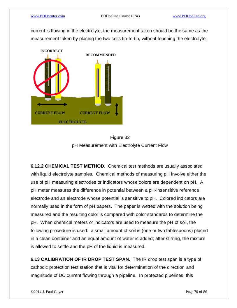
www.PDHcenter.com PDHonline Course C743 www.PDHonline.org
©2014 J. Paul Guyer Page 70 of 86
current is flowing in the electrolyte, the measurement taken should be the same as the
measurement taken by placing the two cells tip-to-tip, without touching the electrolyte.
Figure 32
pH Measurement with Electrolyte Current Flow
6.12.2 CHEMICAL TEST METHOD. Chemical test methods are usually associated
with liquid electrolyte samples. Chemical methods of measuring pH involve either the
use of pH measuring electrodes or indicators whose colors are dependent on pH. A
pH meter measures the difference in potential between a pH-insensitive reference
electrode and an electrode whose potential is sensitive to pH. Colored indicators are
normally used in the form of pH papers. The paper is wetted with the solution being
measured and the resulting color is compared with color standards to determine the
pH. When chemical meters or indicators are used to measure the pH of soil, the
following procedure is used: a small amount of soil is (one or two tablespoons) placed
in a clean container and an equal amount of water is added; after stirring, the mixture
is allowed to settle and the pH of the liquid is measured.
6.13 CALIBRATION OF IR DROP TEST SPAN. The IR drop test span is a type of
cathodic protection test station that is vital for determination of the direction and
magnitude of DC current flowing through a pipeline. In protected pipelines, this
ELECTROLYTE
CURRENT FLOW CURRENT FLOW
RECOMMENDED INCORRECT
www.PDHcenter.com PDHonline Course C743 www.PDHonline.org
©2014 J. Paul Guyer Page 71 of 86
information can be used to verify current distribution, look for stray or interference
current, and the area of influence of installed rectifiers. In unprotected pipelines, this
information can be used to find anodic areas, and to find discharge or pickup areas of
stray or interference currents. This method uses the metallic pipeline or cable as a
shunt, which is then calibrated and used to measure a millivolt “IR Drop,” from which
the current can be calculated. A known amount of DC current is applied to the pipeline
and the voltage drop across the length is measured. The resistance can be estimated
if the size of the pipeline and distance of the test span is accurately known. The line
current can be determined by the null ammeter method, using a Multi-Combination
meter. One other method for determining the direction and magnitude of DC current
flowing through a pipeline is to use a clamp-on milliammeter. This method requires a
very specialized piece of equipment, sized to the pipeline, and an excavation or
access to the pipeline, for placement of the probe around the pipeline.
The preferred method is to measure the actual resistance of the pipe, using test
current. This method does not require knowledge of the pipeline size or wall
thickness, and is not affected by variations in the metal due to composition or
corrosion, variations of resistance due to temperature, or inaccurate lengths of the test
span. The amount of test current required depends on the diameter of the pipeline
and the distance of the test span. The larger the pipeline, the larger the amount of
current required. The shorter the distance of the test span, the larger the amount of
current required.
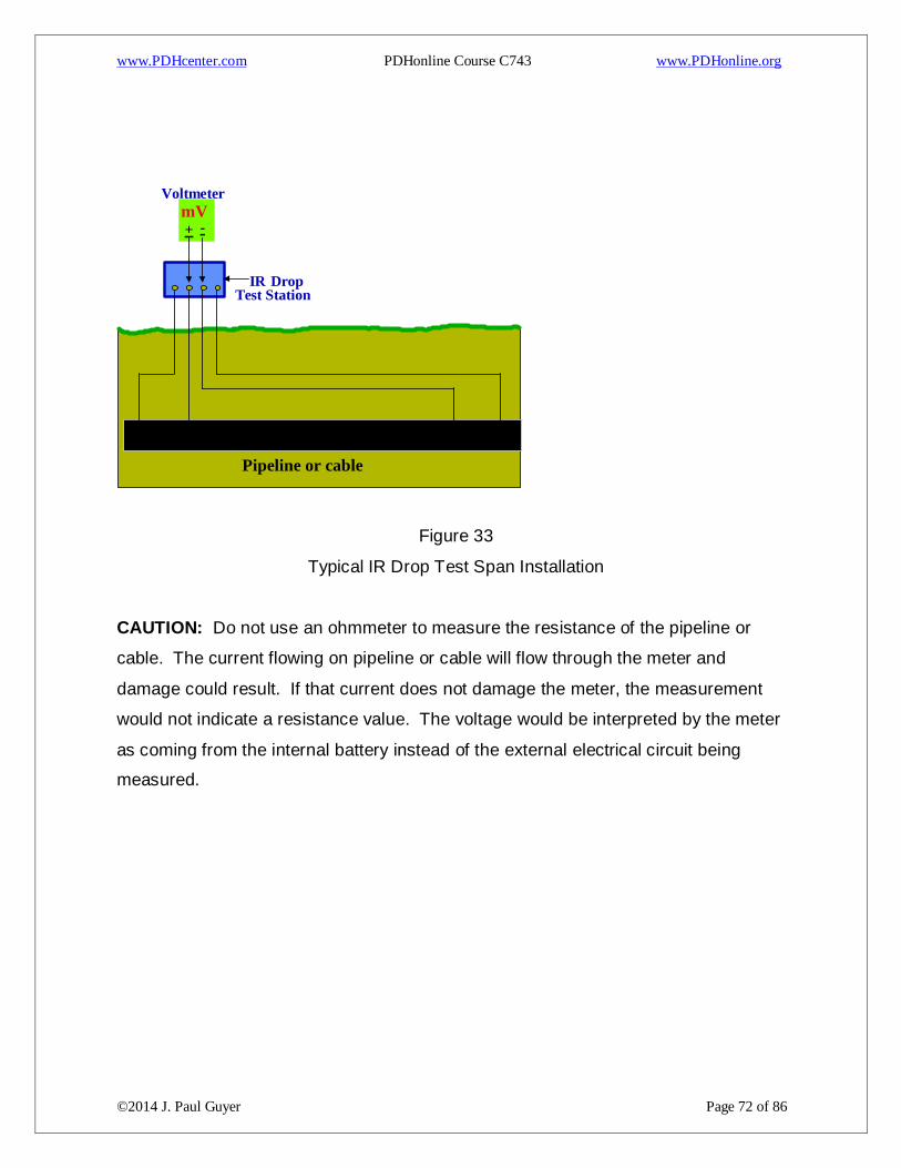
www.PDHcenter.com PDHonline Course C743 www.PDHonline.org
©2014 J. Paul Guyer Page 72 of 86
Figure 33
Typical IR Drop Test Span Installation
CAUTION: Do not use an ohmmeter to measure the resistance of the pipeline or
cable. The current flowing on pipeline or cable will flow through the meter and
damage could result. If that current does not damage the meter, the measurement
would not indicate a resistance value. The voltage would be interpreted by the meter
as coming from the internal battery instead of the external electrical circuit being
measured.
Voltmeter
- +
Test Station IR
Drop
mV
Pipeline or cable
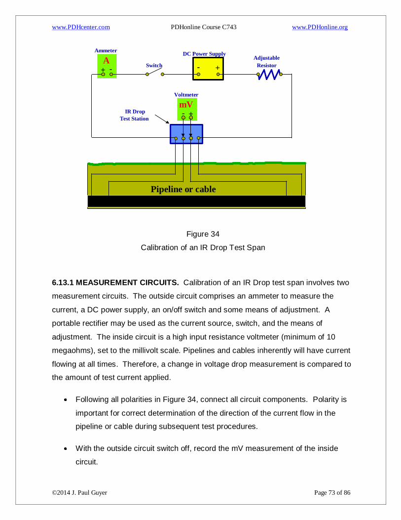
www.PDHcenter.com PDHonline Course C743 www.PDHonline.org
©2014 J. Paul Guyer Page 73 of 86
Figure 34
Calibration of an IR Drop Test Span
6.13.1 MEASUREMENT CIRCUITS. Calibration of an IR Drop test span involves two
measurement circuits. The outside circuit comprises an ammeter to measure the
current, a DC power supply, an on/off switch and some means of adjustment. A
portable rectifier may be used as the current source, switch, and the means of
adjustment. The inside circuit is a high input resistance voltmeter (minimum of 10
megaohms), set to the millivolt scale. Pipelines and cables inherently will have current
flowing at all times. Therefore, a change in voltage drop measurement is compared to
the amount of test current applied.
Following all polarities in Figure 34, connect all circuit components. Polarity is
important for correct determination of the direction of the current flow in the
pipeline or cable during subsequent test procedures.
With the outside circuit switch off, record the mV measurement of the inside
circuit.
Voltmeter
- + Test Station
IR Drop mV
Pipeline or cable
Ammeter
- +
A - +
DC Power Supply
Switch Adjustable
Resistor

www.PDHcenter.com PDHonline Course C743 www.PDHonline.org
©2014 J. Paul Guyer Page 74 of 86
Starting at a low current level, turn the outside circuit switch on and adjust
current up to the desired test current. Record the measurement of the test
current.
With outside circuit remaining on, record the mV measurement of the inside
circuit.
Apply this data to the following formulas:

www.PDHcenter.com PDHonline Course C743 www.PDHonline.org
©2014 J. Paul Guyer Page 75 of 86

www.PDHcenter.com PDHonline Course C743 www.PDHonline.org
©2014 J. Paul Guyer Page 76 of 86
Record the resistance of the test span and the calibration factor established. If the
temperature of the pipeline or cable remains constant, this calibration factor can be
stenciled on the IR drop test station and used for future measurements. If doubt exists
or temperatures change, perform the calibration steps each time measurements are
taken.
6.13.2 DIRECTION OF CURRENT FLOW. Direction of current flow is determined by
the polarity of the mV reading taken on the inside circuit. For example, using Figure
35, a positive IR drop indicates current flow from right to left, while a negative IR drop
would indicate current flow from left to right.
Figure 35
IR Drop Test Span, Direction Of Current Flow
6.13.3 RESISTANCE OF THE PIPELINE. The resistance of the pipeline can be
calculated if the distance of the test span is known and the size of the pipeline is
accurately known. Resistance joints or insulators cannot be present on the pipeline in
the test span. Variations in temperature will adversely affect the accuracy of these
calculations.
Voltmeter - +
Pipeline or cable
+4.32 mV
Voltmeter - +
Pipeline or cable
-4.32 mV

www.PDHcenter.com PDHonline Course C743 www.PDHonline.org
©2014 J. Paul Guyer Page 77 of 86
The mV IR drop is measured by using a voltmeter on the mV scale as shown in Figure
35. Following all polarities in Figure 35, connect the meter to the inside circuit and
record the measurement. Polarity is important for correct determination of the
direction of the current flow in the pipeline or cable during subsequent test procedures.
The resistance is estimated using Table 3. The resistance is given in millionths of an
ohm (0.000001 ohms) per linear foot of pipeline. This resistance value must be
multiplied by the number of feet in the test span (distance in feet of the pipeline
between the actual connection points of the test station leads to the pipeline).

www.PDHcenter.com PDHonline Course C743 www.PDHonline.org
©2014 J. Paul Guyer Page 78 of 86
Nominal
Pipeline Size
(inches)
Outside
Diameter
(inches)
Wall
Thickness
(inches)
Weight per
Foot (pounds)
Resistance per
Foot (micro ohms)
2 2.375 0.154 3.65 79.20
4 4.500 0.237 10.80 26.80
6 6.625 0.280 19.00 15.20
8 8.625 0.322 28.60 10.10
10 10.750 0.365 40.50 7.13
12 12.750 0.375 49.60 5.82
14 14.000 0.375 54.60 5.29
16 16.000 0.375 62.60 4.61
18 18.00 0.375 70.60 4.09
20 20.000 0.375 78.60 3.68
22 22.000 0.375 86.60 3.34
24 24.000 0.375 94.60 3.06
26 26.000 0.375 102.60 2.82
28 28.000 0.375 110.60 2.62
30 30.000 0.375 118.70 2.44
32 32.000 0.375 126.60 2.28
34 34.000 0.375 134.60 2.15
36 36.000 0.375 142.60 2.03
Table 4
Estimated Resistance of Steel Pipelines
6.13.3.3 This data is then applied to the following formula:
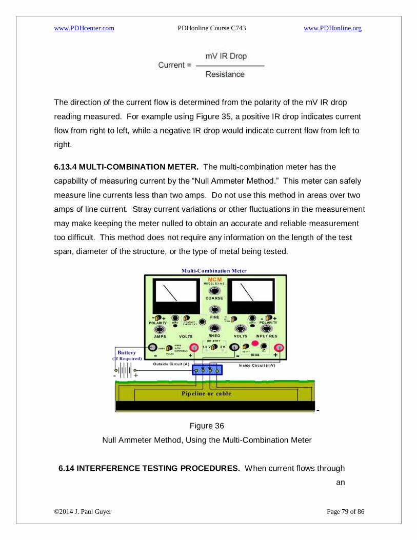
www.PDHcenter.com PDHonline Course C743 www.PDHonline.org
©2014 J. Paul Guyer Page 79 of 86
The direction of the current flow is determined from the polarity of the mV IR drop
reading measured. For example using Figure 35, a positive IR drop indicates current
flow from right to left, while a negative IR drop would indicate current flow from left to
right.
6.13.4 MULTI-COMBINATION METER. The multi-combination meter has the
capability of measuring current by the “Null Ammeter Method.” This meter can safely
measure line currents less than two amps. Do not use this method in areas over two
amps of line current. Stray current variations or other fluctuations in the measurement
may make keeping the meter nulled to obtain an accurate and reliable measurement
too difficult. This method does not require any information on the length of the test
span, diameter of the structure, or the type of metal being tested.
-
Figure 36
Null Ammeter Method, Using the Multi-Combination Meter
6.14 INTERFERENCE TESTING PROCEDURES. When current flows through
an

www.PDHcenter.com PDHonline Course C743 www.PDHonline.org
©2014 J. Paul Guyer Page 80 of 86
electrolyte, it follows the path of least electrical resistance. If a metal structure is
immersed in the current-carrying electrolyte, it is likely to present a low resistance path
for the flow of current. At the point where electrons enter the structure from the
electrolyte, corrosion will be accelerated. Where electrons leave the structure,
corrosion will be reduced. This phenomenon is called cathodic interference. Cathodic
interference is commonly encountered on buried structures. Cathodic interference can
be detected by electrical measurements and can be controlled. Cathodic protection
sometimes causes undesirable effects on structures not connected to the protection
system. This occurs because some current is picked up by these “foreign” structures
at one point, and in attempting to return to the source and complete the circuit, is
discharged at another point. Corrosion occurs at the current discharge point. Current
can cause corrosion damage by passing between two structures or across high-
resistance joints in the same structure. Sources of interference currents may be
constant or fluctuating. Constant current sources have essentially constant direct
current output, such as cathodic protection rectifiers and thermoelectric generators.
Fluctuating current sources have a fluctuating direct current output, such as direct
current electrified railway systems, coal mine haulage systems and pumps, welding
machines, direct current power systems, and telluric currents.
Mitigation can usually be accomplished by installing an electrical bond between the
unprotected structure (at the location of maximum discharge) and the protected
structure. Other mitigation methods include breaking the continuity of the foreign
pipeline, coating the foreign pipeline pickup area, coating the protected pipeline in the
discharge area of the foreign pipeline, and using galvanic anodes to apply current to
the discharge area of the foreign pipeline (and also provide an alternate current
discharge point).
6.14.1 INTERFERENCE FROM CATHODIC PROTECTION RECTIFIERS. Cathodic
protection systems are a major source of stray current on other metallic structures.
Structures not electrically connected to the protected structures are considered to be
“foreign” structures.” A foreign structure may provide an alternate path for the current
flowing from the impressed current anodes to a protected structure. If this path is of

www.PDHcenter.com PDHonline Course C743 www.PDHonline.org
©2014 J. Paul Guyer Page 81 of 86
sufficiently low resistance, significant current flow will occur. Since there is no metallic
return path, the current will discharge from the surface of the foreign structure to the
electrolyte to return to its source, resulting in severe corrosion.
Testing requires cooperation by the owners of the structures involved. Such
cooperation is best effected by a corrosion coordinating committee; all companies
operating underground or underwater structures, and particularly those under cathodic
protection, should be members of such a committee. A list of most existing
committees may be obtained from the National Association of Corrosion Engineers,
P.O. Box 218340 Houston, TX, 77218-8340. Interference testing is usually performed
when new cathodic protection systems are first installed but is sometimes detected
through routine field measurements. Good record keeping is very useful in preventing
cathodic interference problems, as any system changes, particularly additions of new
buried structures, can be more easily determined when proper records are kept.
Interference tests must be made on all structures adjacent to a cathodic protection
system to determine effects and to allow design of mitigation measures.
Cathodic interference can be detected by measuring structure-to-soil potentials,
potential gradients and current flow (IR drop) with cathodic protection current or
resistance bonds on and/or cycled on and off. Structure-to-soil potentials give
indications of interference only when measured in an area of current discharge or
pickup on the foreign structure. Abnormal or unusual current distribution on a
protected structure indicates possible interference on a foreign structure. Current flow
(IR drop) readings show the relationship between pickup and discharge areas on a
foreign structure. A cathodic protection rectifier output contains a waveform, which
results in a pulsating DC signal. Presence of this pulsating DC on foreign structures
indicates interference from a rectifier. When conducting current requirement tests or
initially energizing impressed current cathodic protection systems, all companies
owning underground structures in the area should be notified and coordination tests
made with those interested. Current drainage requirements for each structure, from
tests at various anode locations, can be determined.
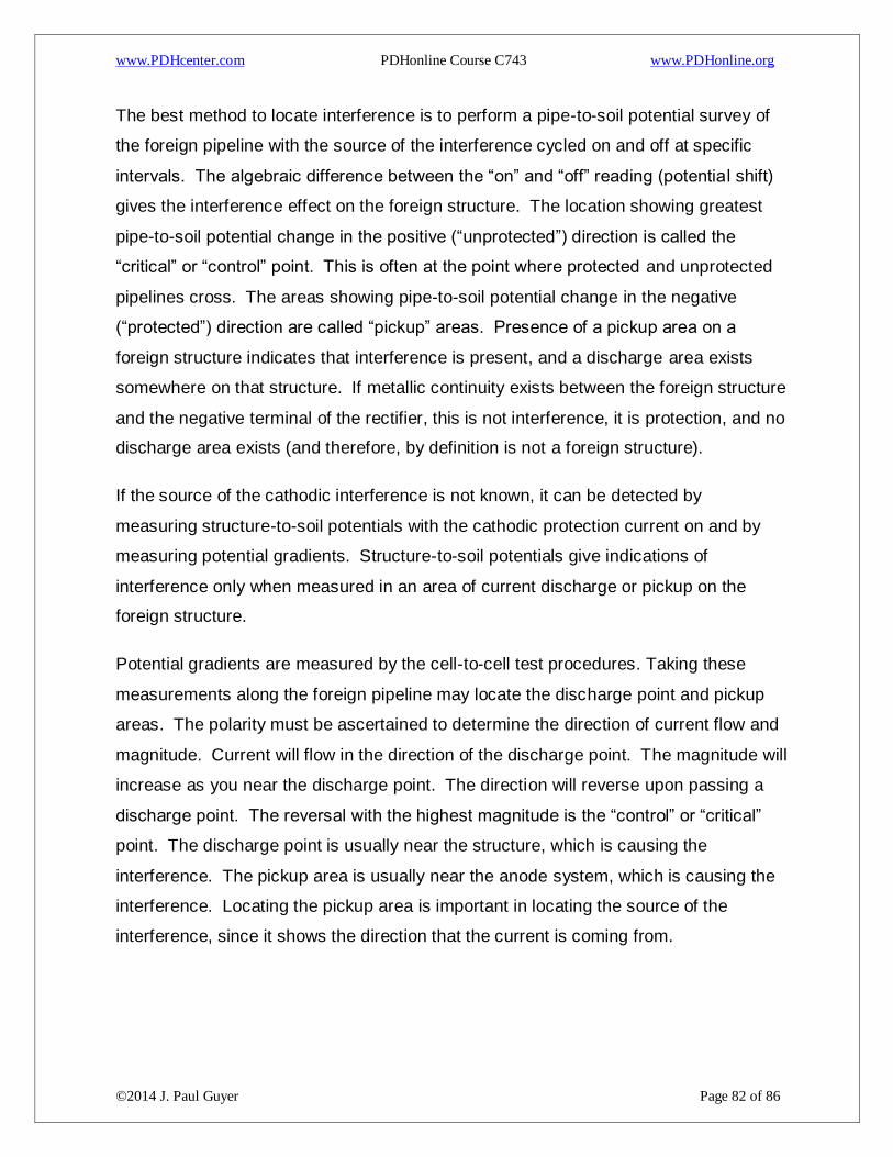
www.PDHcenter.com PDHonline Course C743 www.PDHonline.org
©2014 J. Paul Guyer Page 82 of 86
The best method to locate interference is to perform a pipe-to-soil potential survey of
the foreign pipeline with the source of the interference cycled on and off at specific
intervals. The algebraic difference between the “on” and “off” reading (potential shift)
gives the interference effect on the foreign structure. The location showing greatest
pipe-to-soil potential change in the positive (“unprotected”) direction is called the
“critical” or “control” point. This is often at the point where protected and unprotected
pipelines cross. The areas showing pipe-to-soil potential change in the negative
(“protected”) direction are called “pickup” areas. Presence of a pickup area on a
foreign structure indicates that interference is present, and a discharge area exists
somewhere on that structure. If metallic continuity exists between the foreign structure
and the negative terminal of the rectifier, this is not interference, it is protection, and no
discharge area exists (and therefore, by definition is not a foreign structure).
If the source of the cathodic interference is not known, it can be detected by
measuring structure-to-soil potentials with the cathodic protection current on and by
measuring potential gradients. Structure-to-soil potentials give indications of
interference only when measured in an area of current discharge or pickup on the
foreign structure.
Potential gradients are measured by the cell-to-cell test procedures. Taking these
measurements along the foreign pipeline may locate the discharge point and pickup
areas. The polarity must be ascertained to determine the direction of current flow and
magnitude. Current will flow in the direction of the discharge point. The magnitude will
increase as you near the discharge point. The direction will reverse upon passing a
discharge point. The reversal with the highest magnitude is the “control” or “critical”
point. The discharge point is usually near the structure, which is causing the
interference. The pickup area is usually near the anode system, which is causing the
interference. Locating the pickup area is important in locating the source of the
interference, since it shows the direction that the current is coming from.
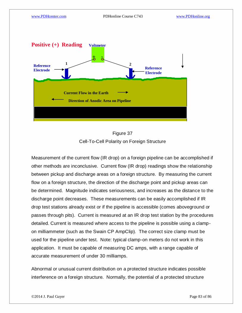
www.PDHcenter.com PDHonline Course C743 www.PDHonline.org
©2014 J. Paul Guyer Page 83 of 86
Figure 37
Cell-To-Cell Polarity on Foreign Structure
Measurement of the current flow (IR drop) on a foreign pipeline can be accomplished if
other methods are inconclusive. Current flow (IR drop) readings show the relationship
between pickup and discharge areas on a foreign structure. By measuring the current
flow on a foreign structure, the direction of the discharge point and pickup areas can
be determined. Magnitude indicates seriousness, and increases as the distance to the
discharge point decreases. These measurements can be easily accomplished if IR
drop test stations already exist or if the pipeline is accessible (comes aboveground or
passes through pits). Current is measured at an IR drop test station by the procedures
detailed. Current is measured where access to the pipeline is possible using a clamp-
on milliammeter (such as the Swain CP AmpClip). The correct size clamp must be
used for the pipeline under test. Note: typical clamp-on meters do not work in this
application. It must be capable of measuring DC amps, with a range capable of
accurate measurement of under 30 milliamps.
Abnormal or unusual current distribution on a protected structure indicates possible
interference on a foreign structure. Normally, the potential of a protected structure
Voltmeter
- +
1 2 Reference
Electrode Electrode
Reference
Current Flow in the Earth
Direction of Anodic Area on Pipeline
Positive (+) Reading
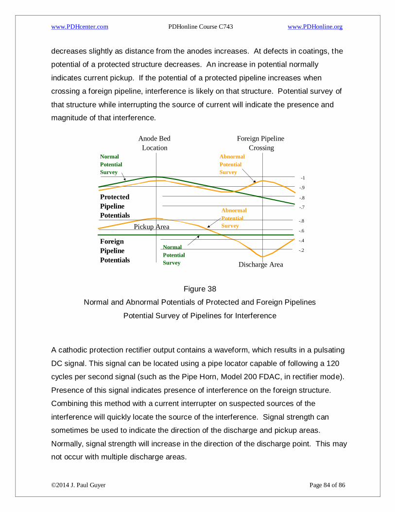
www.PDHcenter.com PDHonline Course C743 www.PDHonline.org
©2014 J. Paul Guyer Page 84 of 86
decreases slightly as distance from the anodes increases. At defects in coatings, the
potential of a protected structure decreases. An increase in potential normally
indicates current pickup. If the potential of a protected pipeline increases when
crossing a foreign pipeline, interference is likely on that structure. Potential survey of
that structure while interrupting the source of current will indicate the presence and
magnitude of that interference.
Figure 38
Normal and Abnormal Potentials of Protected and Foreign Pipelines
Potential Survey of Pipelines for Interference
A cathodic protection rectifier output contains a waveform, which results in a pulsating
DC signal. This signal can be located using a pipe locator capable of following a 120
cycles per second signal (such as the Pipe Horn, Model 200 FDAC, in rectifier mode).
Presence of this signal indicates presence of interference on the foreign structure.
Combining this method with a current interrupter on suspected sources of the
interference will quickly locate the source of the interference. Signal strength can
sometimes be used to indicate the direction of the discharge and pickup areas.
Normally, signal strength will increase in the direction of the discharge point. This may
not occur with multiple discharge areas.
Anode Bed
Location
Foreign Pipeline
Crossing Normal Potential Survey
Abnormal Potential Survey
Protected
Pipeline
Potentials
Foreign
Pipeline
Potentials
Normal Potential Survey
Pickup Area
Discharge Area
-1
-.9
-.8
-.7
-.8
-.6
-.4
-.2
Abnormal Potential Survey
www.PDHcenter.com PDHonline Course C743 www.PDHonline.org
©2014 J. Paul Guyer Page 85 of 86
Another method of interference testing involves using an experimental drainage bond
between structures. Proper drainage can be determined by trial-and error, using a
variable resistor to alter drainage current. Required drainage current can also be
computed from test data. When the same owner maintains the protected structure
and the foreign structure, this method may be easily used. The source of interference
is cycled on and off at specific intervals and the bond resistance is adjusted until no
potential shift occurs on the foreign structure. When site conditions warrant, the bond
may be sized to apply partial or full protection to the foreign structure. If the foreign
structure is small or well coated, and the protected structure is poorly coated, this
option may be taken when sufficient CP current is still available to maintain protection
on the protected structure.
6.14.2 INTERFERENCE FROM VARIABLE (FLUCTUATING) SOURCES. While
interference testing determines effects of steady stray currents, another type of stray
current survey analyzes fluctuating stray currents. Fluctuating or periodic changes in
structure-to electrolyte voltage values and unusual or fluctuating currents are indicative
of stray currents. Stray currents may affect structures just as cathodic protection does.
Structures may be protected or damaged by stray currents, depending on whether
current is flowing to or from the structure. Such analysis is specialized and requires
study to master all techniques. The basic principles are the same as in the previous
paragraph. The difference is that the stray current is not present all the time. The
simultaneous use of data loggers or recording devices at many points on the foreign
structure will indicate the same information as above. Locating the discharge point(s)
and pickup areas is still crucial. In this case, determining the time of the interference is
also crucial.
All the basic measurements can be used in studying fluctuating stray currents.
Perhaps the most informative are measurements similar to those used in interference
testing: structure-to-electrolyte potentials and IR drops along structure or electrolyte.
Methods of analysis, however, are different, and specialized equipment is used. The
major concern in performing a stray current survey is to find out the degree of damage
and determine the source of the currents.

www.PDHcenter.com PDHonline Course C743 www.PDHonline.org
©2014 J. Paul Guyer Page 86 of 86
Measurement of the foreign pipeline potentials is commonly used to determine the
pickup and discharge areas. Using data loggers or recording devices, many locations
on the foreign structure are monitored simultaneously. This data is then charted to
analyze for the presence of interference. When the exact moment of interference is
determined, all potential readings taken at that instant are used to determine the
discharge and pickup points. Data taken is used to locate areas for taking additional
data. Once gathered, this data is used exactly like the data for cathodic interference
detailed. Abnormal potentials on other structures may also be used for further
analysis. Once the pickup area and time is determined, the source of the current may
be located.
Another method of finding these points is through current measurements. To
determine the pickup and discharge points in fluctuating stray current areas, data from
several test points are plotted over a period of time. Current values on the several
locations on the foreign structure (recorded from IR drop test spans or a clamp-on
milliammeter) are plotted over a period of time. The current must be measured at
several points simultaneously, sufficient readings being made to cover the range of
variation of the current (usually at least 24 hours). By analyzing the current direction
and magnitude at the time the interference is occurring, the relationship and direction
of the pickup areas and discharge areas can be determined. Once the time of
interference is known, the area of pickup can be searched for possible sources of the
current pickup. Outside of the necessity of taking simultaneous readings due to the
fluctuating current, this method is the same as conventional line current
measurements.


![cathodic protection in practise · 2 [CATHODIC PROTECTION/BM] CATHODIC PROTECTION P E FRANCIS 1 INTRODUCTION The first practical use of cathodic protection is generally credited to](https://img.pdfslide.us/doc/110x75/5ace93c87f8b9ae2138b87e4/cathodic-protection-in-cathodic-protectionbm-cathodic-protection-p-e-francis.jpg)