Embed Size (px)
Citation preview

An Introduction to Agricultural Tile Drainage
John Panuska PhD, PE
Natural Resources Extension Specialist Biological Systems Engineering Department
UW Madison
SWCS Meeting September 21, 2012

Tile System Design Objectives
Maintain water table at proper level for healthiest plant growth.
Keep soil voids free of excess water, which
permits air flow and allows important biological processes to take place in soil.
Minimize inefficient equipment operation caused by wet areas.

Improved Root Development
Tile System Design Objectives
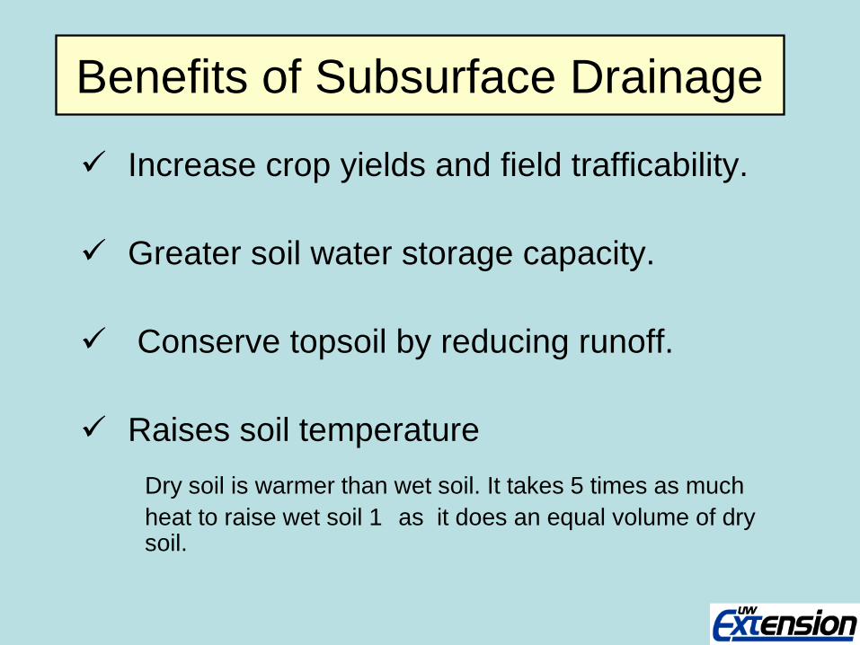
Benefits of Subsurface Drainage
Increase crop yields and field trafficability.
Greater soil water storage capacity. Conserve topsoil by reducing runoff.
Raises soil temperature
Dry soil is warmer than wet soil. It takes 5 times as much heat to raise wet soil 1 as it does an equal volume of dry
soil.
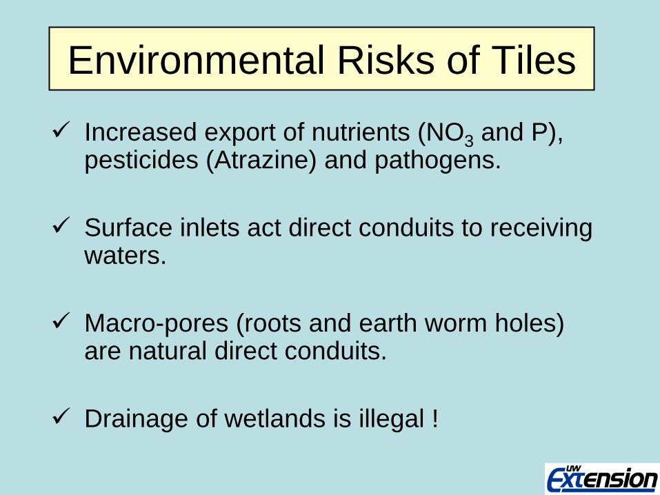
Environmental Risks of Tiles Increased export of nutrients (NO3 and P),
pesticides (Atrazine) and pathogens.
Surface inlets act direct conduits to receiving waters.
Macro-pores (roots and earth worm holes) are natural direct conduits.
Drainage of wetlands is illegal !
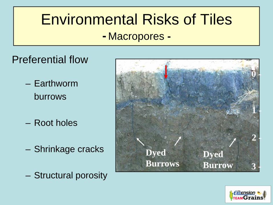
Environmental Risks of Tiles - Macropores -
Preferential flow
– Earthworm burrows
– Root holes
– Shrinkage cracks
– Structural porosity
Dyed Burrows
Dyed Burrow
0 -
1 -
2 -
3 -

Drainable Water
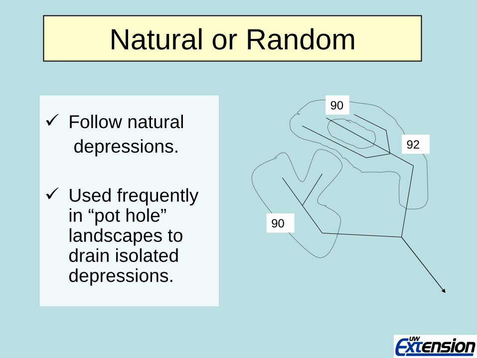
Natural or Random
Follow natural depressions. Used frequently
in “pot hole” landscapes to drain isolated depressions.
90
92
90
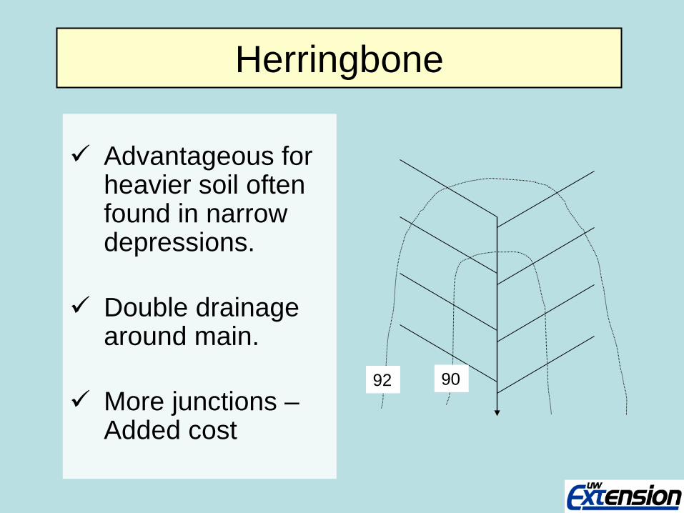
Herringbone
Advantageous for heavier soil often found in narrow depressions.
Double drainage
around main. More junctions –
Added cost
90 92

Gridiron
Drainage of level areas, uniform slopes
and soils w/ wide-spread wet areas.
One main or sub-
main serves as many laterals as possible
Outlet
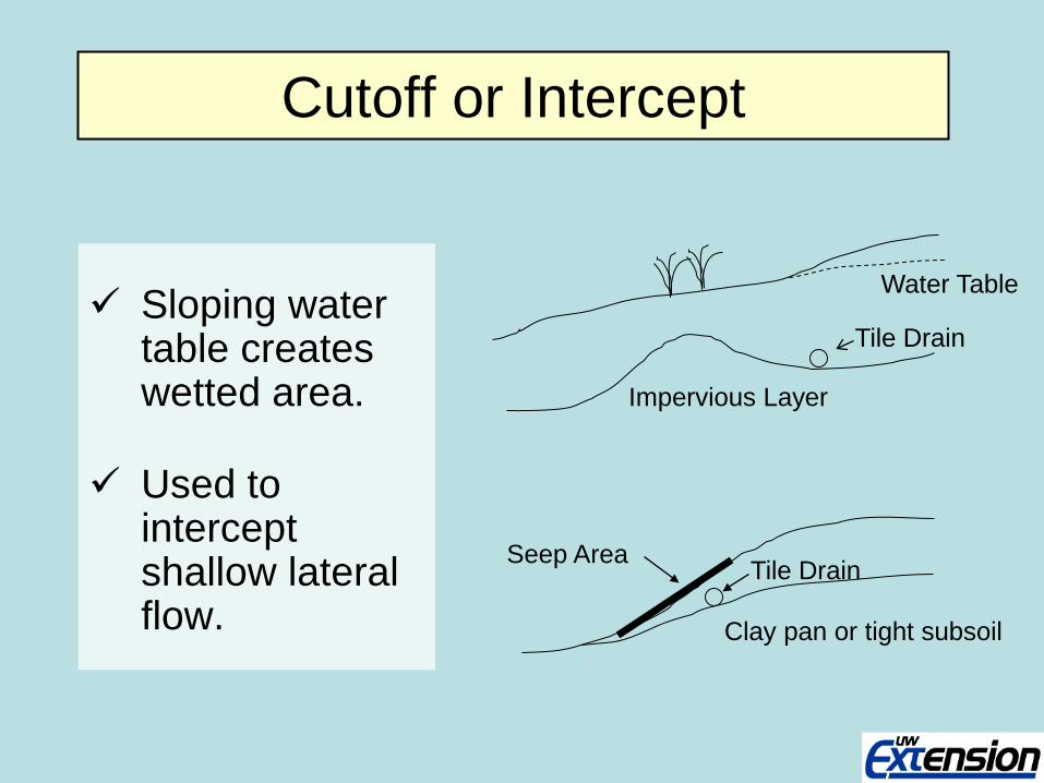
Cutoff or Intercept
Sloping water table creates wetted area.
Used to intercept shallow lateral flow.
Impervious Layer
Tile Drain
Water Table
Clay pan or tight subsoil
Seep Area Tile Drain
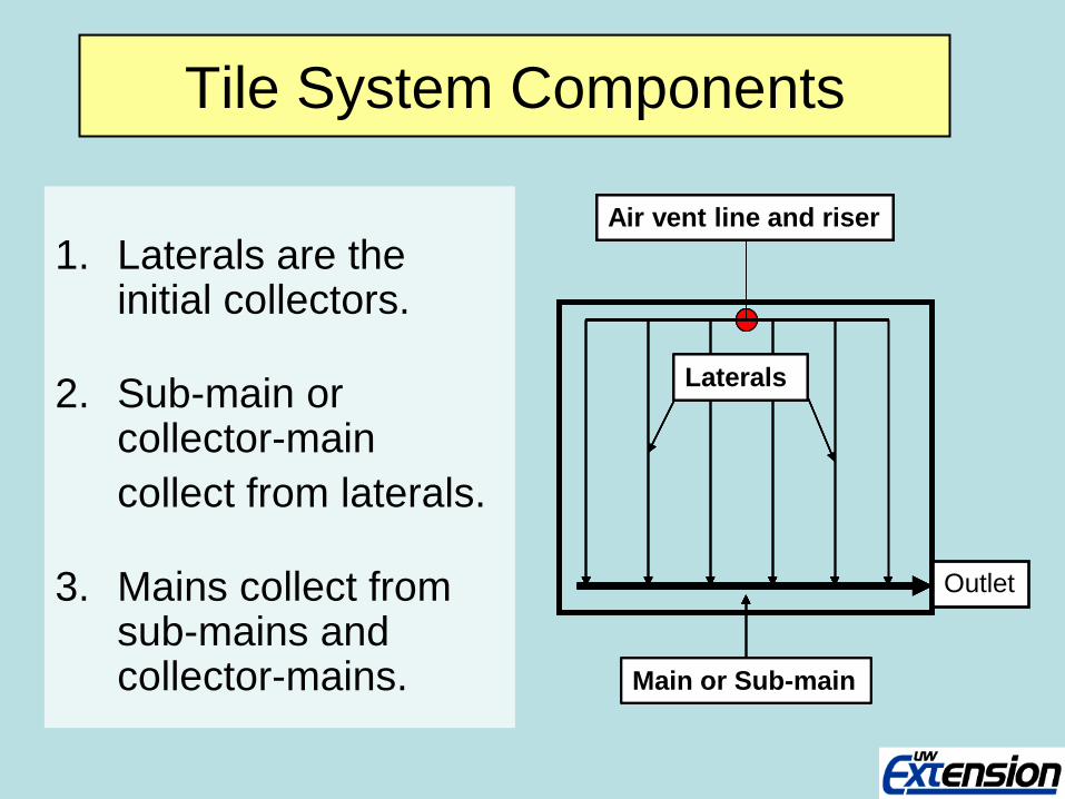
Tile System Components
1. Laterals are the initial collectors.
2. Sub-main or collector-main
collect from laterals.
3. Mains collect from sub-mains and collector-mains. Main or Sub-main
Air vent line and riser
Main or Sub-main
Air vent line and riser
Main or Sub-main
Air vent line and riser
Main or Sub-main
Air vent line and riser
Laterals
Main or Sub-main
Air vent line and riser
Laterals
Main or Sub-main
Air vent line and riser
Laterals
Main or Sub-main
Air vent line and riser
Laterals
Outlet
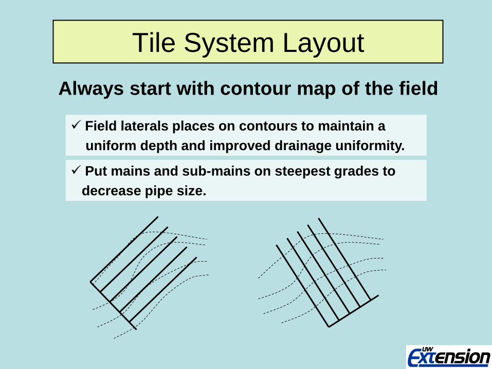
Tile System Layout Always start with contour map of the field
Put mains and sub-mains on steepest grades to decrease pipe size.
Field laterals places on contours to maintain a uniform depth and improved drainage uniformity.
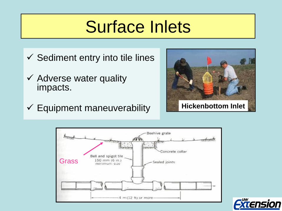
Surface Inlets
Sediment entry into tile lines
Adverse water quality impacts.
Equipment maneuverability
Grass
Hickenbottom Inlet

Blind Inlet (French Drain) Can be used when water quantity to remove is small or
sediment load is high
Do not function satisfactorily for more than a few year
They are expensive to construct, but do not interfere with farming operations
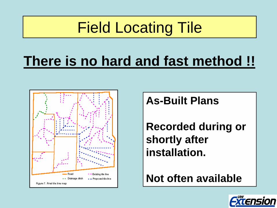
Field Locating Tile
As-Built Plans Recorded during or shortly after installation. Not often available
There is no hard and fast method !!
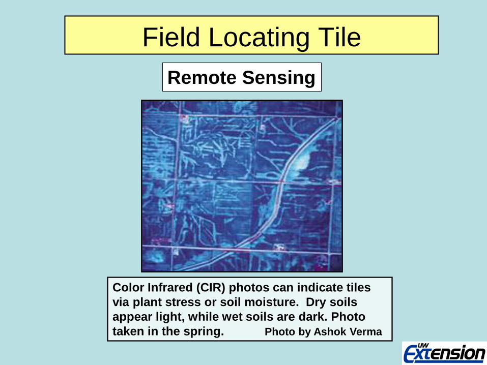
Field Locating Tile Remote Sensing
Color Infrared (CIR) photos can indicate tiles via plant stress or soil moisture. Dry soils appear light, while wet soils are dark. Photo taken in the spring. Photo by Ashok Verma
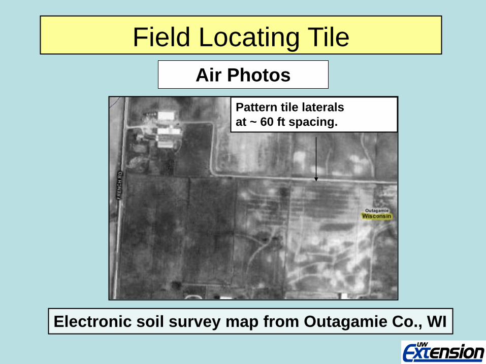
Field Locating Tile
Electronic soil survey map from Outagamie Co., WI
Pattern tile laterals at ~ 60 ft spacing.
Air Photos

Drain spacing, water table depth and crop response
Field Locating Tile
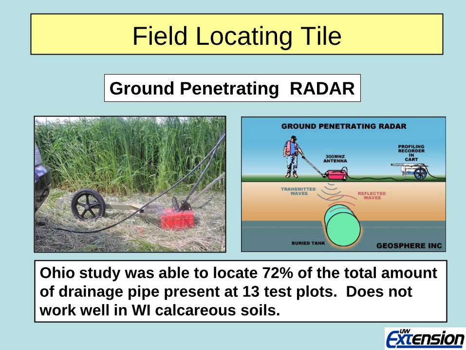
Field Locating Tile
Ground Penetrating RADAR
Ohio study was able to locate 72% of the total amount of drainage pipe present at 13 test plots. Does not work well in WI calcareous soils.
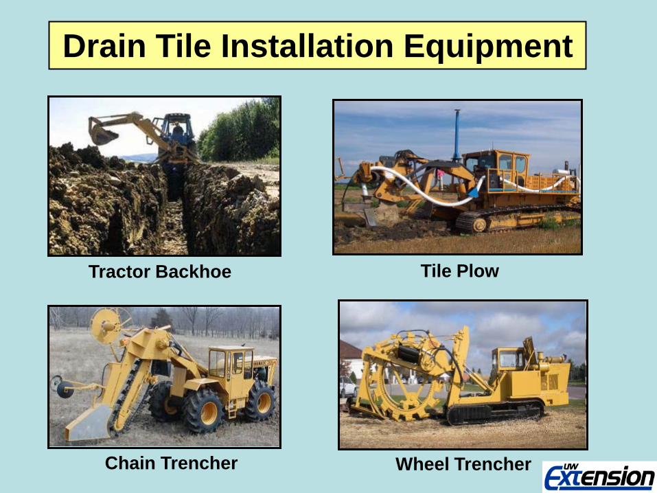
Drain Tile Installation Equipment
Tractor Backhoe Tile Plow
Chain Trencher Wheel Trencher
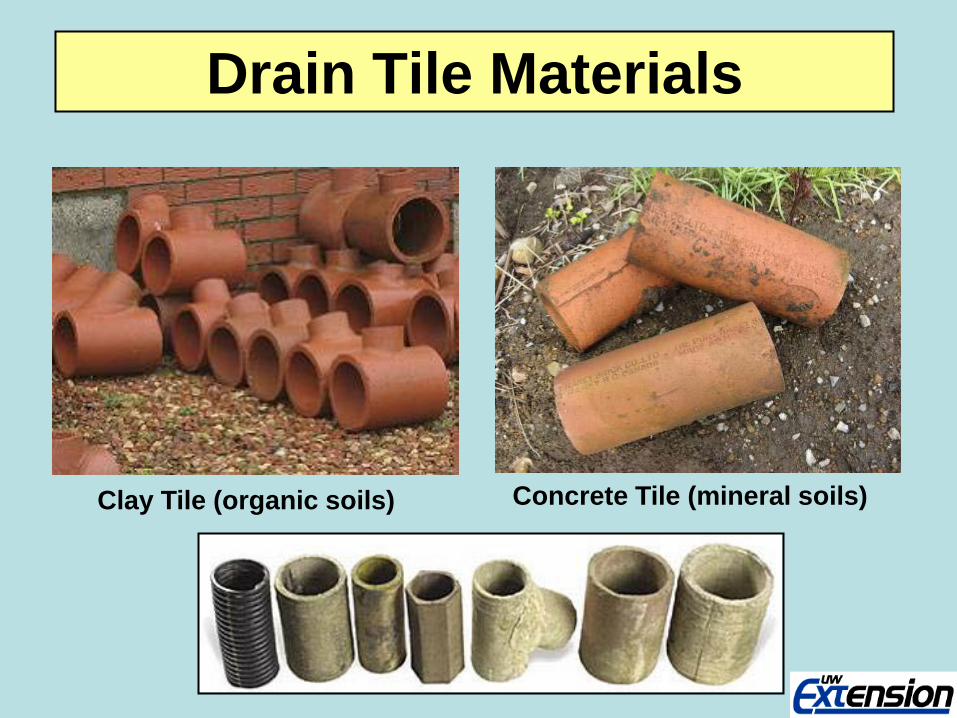
Drain Tile Materials
Clay Tile (organic soils) Concrete Tile (mineral soils)
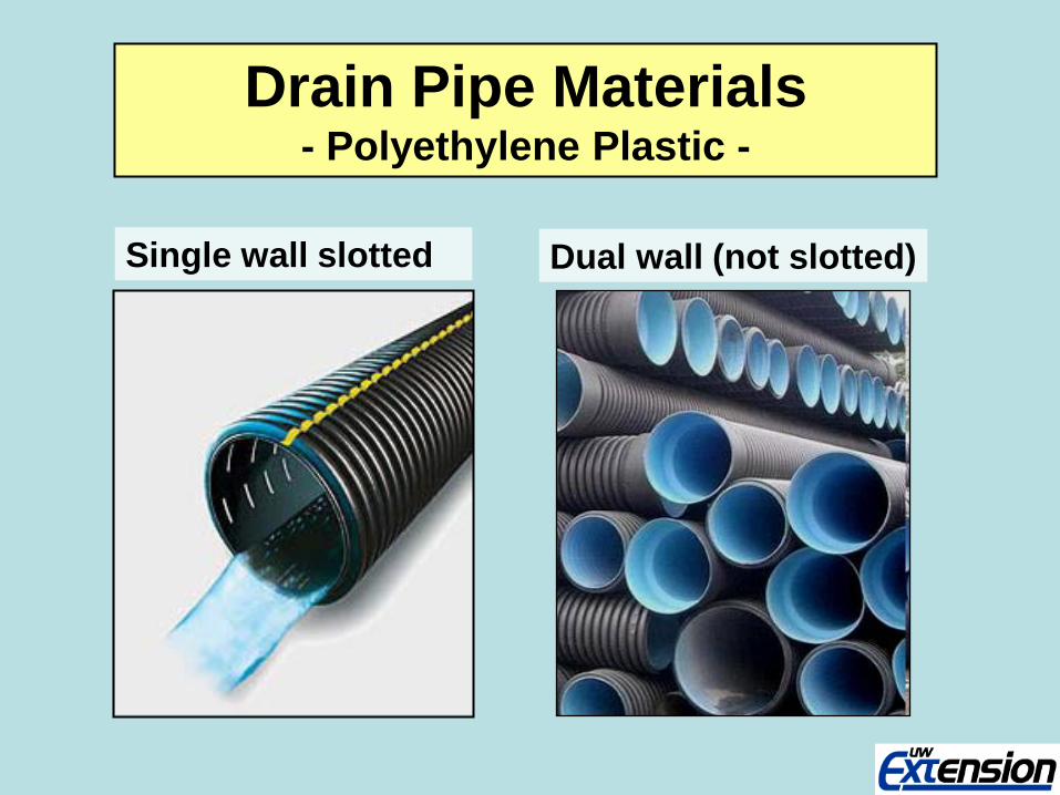
Drain Pipe Materials - Polyethylene Plastic -
Single wall slotted Dual wall (not slotted)
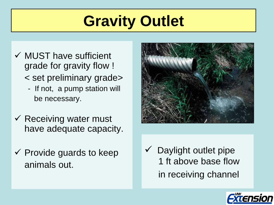
Gravity Outlet
MUST have sufficient grade for gravity flow !
< set preliminary grade> - If not, a pump station will be necessary.
Receiving water must have adequate capacity.
Provide guards to keep animals out.
Daylight outlet pipe 1 ft above base flow in receiving channel
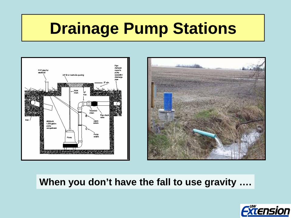
Drainage Pump Stations
When you don’t have the fall to use gravity ….

Hydraulic Design Considerations

Drain System Capacity Drainage Coefficient (Dc) = Depth rate (in/day) Area x (Dc) = [ac] • [in / day] / 23.8 = Flow rate (ft3/sec)
Profile View
Area 1
Plan View
Area 2
1 2
L
S S
Also applies at the whole field scale
Drainage Coefficient
Drainage coefficient (Dc ) is a desired water removal rate.
The Dc equals the volume (depth (in) x area (ac)) of water to be removed from a field in 24 hours.
Drainage area can be computed from the length and spacing of the drains.
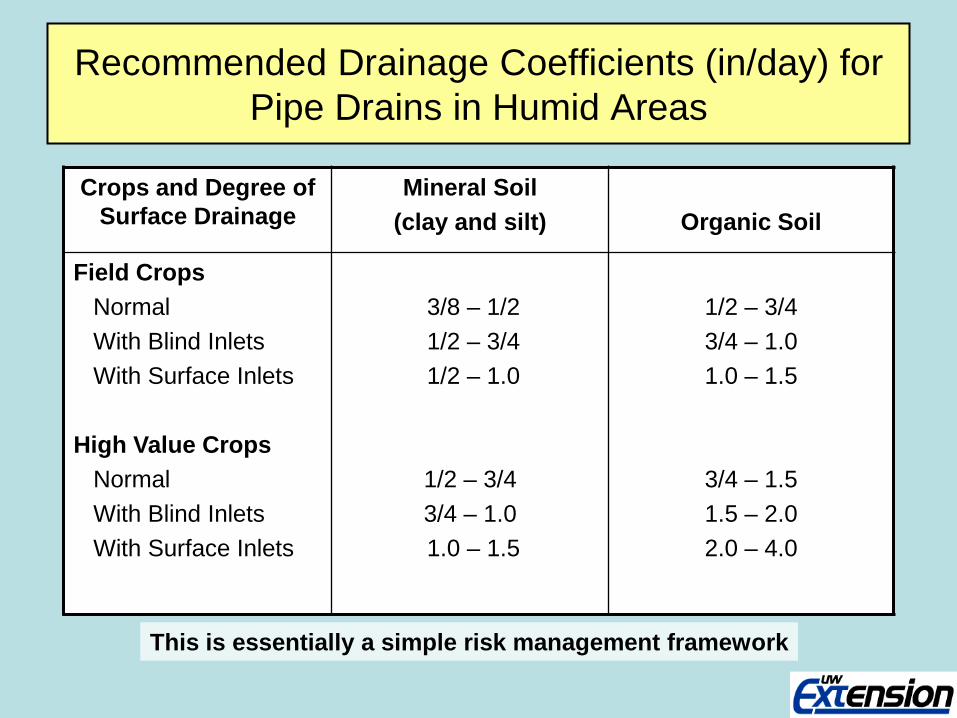
Recommended Drainage Coefficients (in/day) for Pipe Drains in Humid Areas
Crops and Degree of Surface Drainage
Mineral Soil (clay and silt)
Organic Soil
Field Crops Normal With Blind Inlets With Surface Inlets High Value Crops Normal With Blind Inlets With Surface Inlets
3/8 – 1/2 1/2 – 3/4 1/2 – 1.0
1/2 – 3/4 3/4 – 1.0 1.0 – 1.5
1/2 – 3/4 3/4 – 1.0 1.0 – 1.5
3/4 – 1.5 1.5 – 2.0 2.0 – 4.0
This is essentially a simple risk management framework
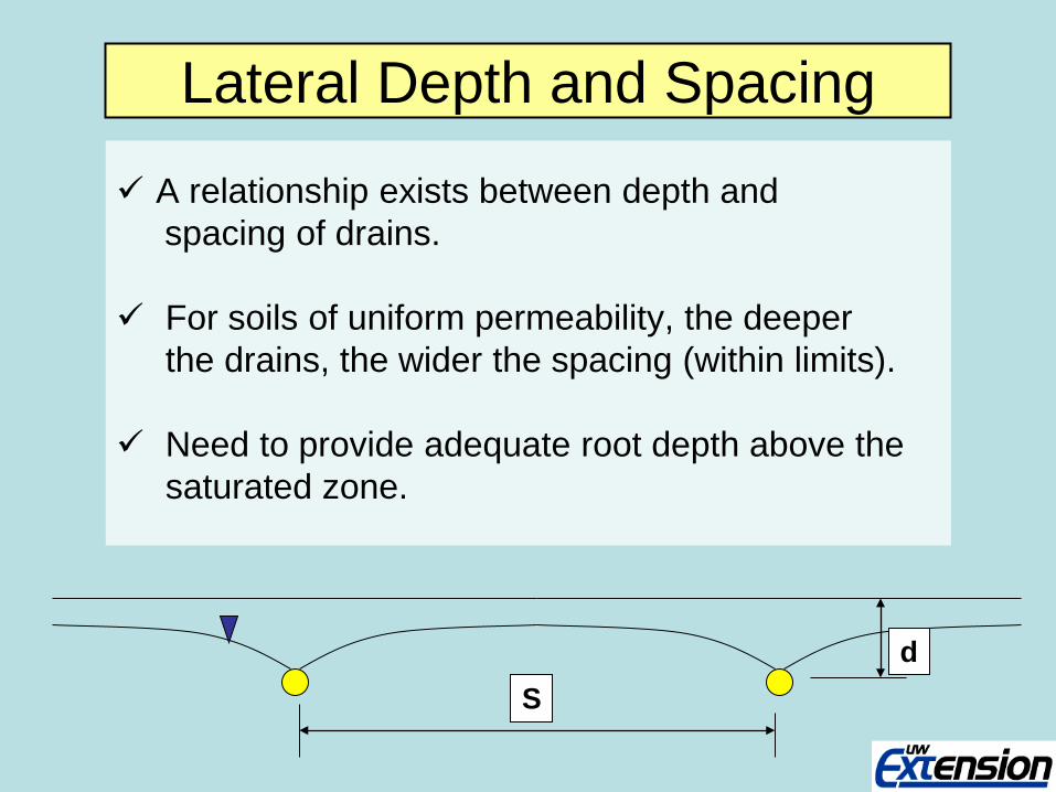
Lateral Depth and Spacing
A relationship exists between depth and spacing of drains. For soils of uniform permeability, the deeper the drains, the wider the spacing (within limits). Need to provide adequate root depth above the saturated zone.
S d
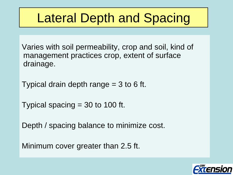
Lateral Depth and Spacing
Varies with soil permeability, crop and soil, kind of management practices crop, extent of surface drainage. Typical drain depth range = 3 to 6 ft. Typical spacing = 30 to 100 ft. Depth / spacing balance to minimize cost. Minimum cover greater than 2.5 ft.
2
21
2
2 )4()8(L
hKL
hdKDC ∗∗+
∗∗∗=
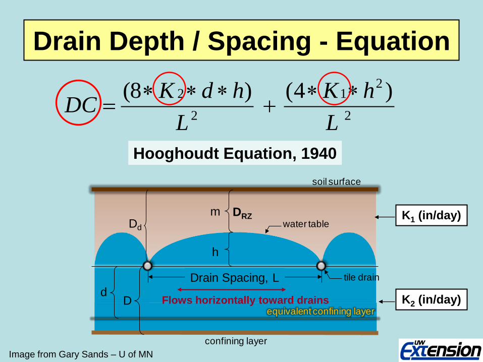
Hooghoudt Equation, 1940
Drain Depth / Spacing - Equation
Image from Gary Sands – U of MN
Dd
m
h
Drain Spacing, L
confining layer
equivalent confining layer
soil surface
Dd water table
tile drain
K1 (in/day)
K2 (in/day) Flows horizontally toward drains
DRZ
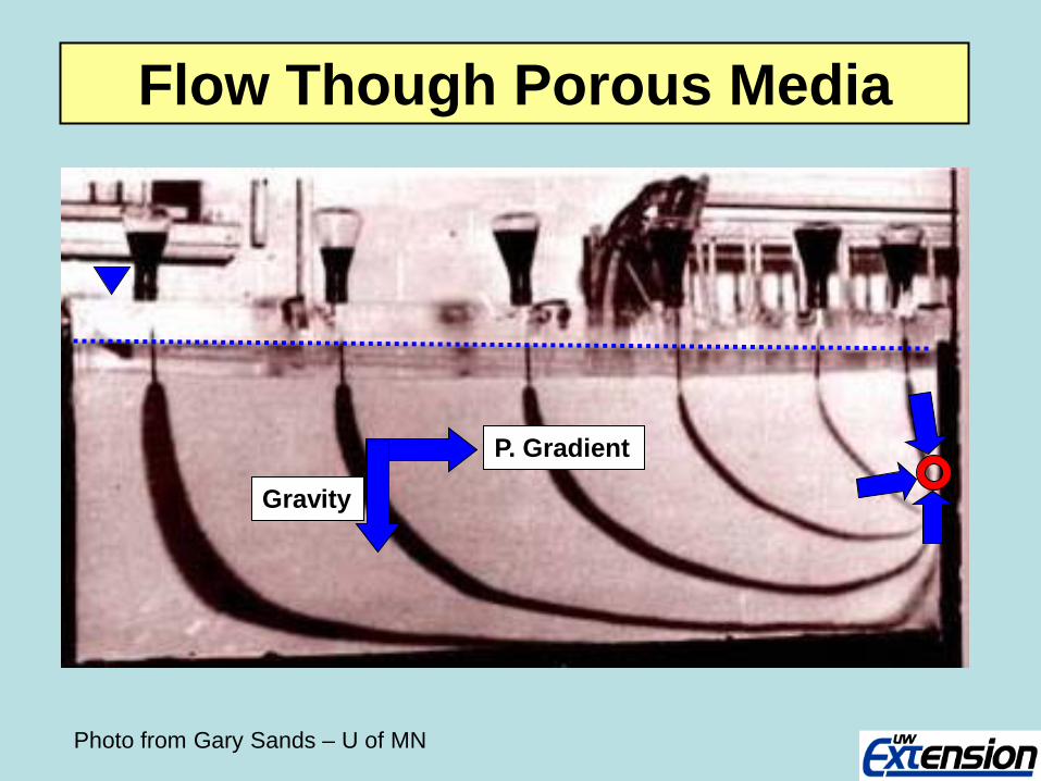
Photo from Gary Sands – U of MN
Flow Though Porous Media
P. Gradient
Gravity
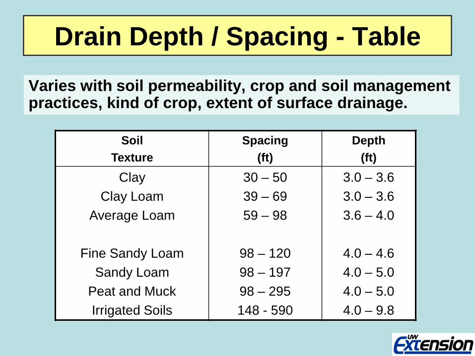
Drain Depth / Spacing - Table
Varies with soil permeability, crop and soil management practices, kind of crop, extent of surface drainage.
Soil Texture
Spacing (ft)
Depth (ft)
Clay Clay Loam
Average Loam
Fine Sandy Loam Sandy Loam
Peat and Muck Irrigated Soils
30 – 50 39 – 69 59 – 98
98 – 120 98 – 197 98 – 295 148 - 590
3.0 – 3.6 3.0 – 3.6 3.6 – 4.0
4.0 – 4.6 4.0 – 5.0 4.0 – 5.0 4.0 – 9.8
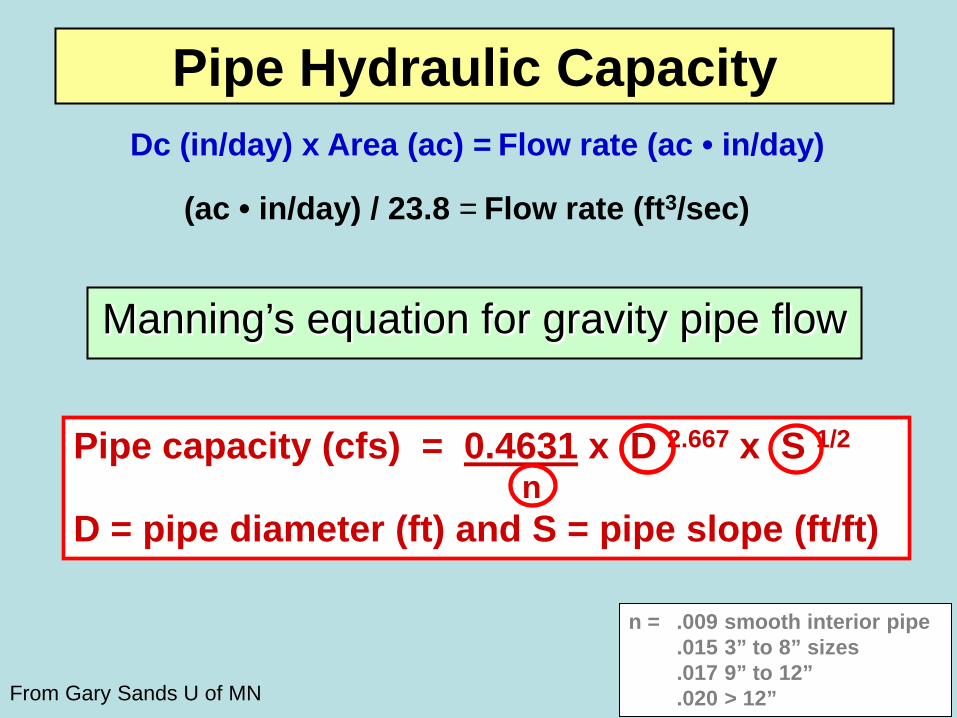
Manning’s equation for gravity pipe flow
n = .009 smooth interior pipe .015 3” to 8” sizes .017 9” to 12” .020 > 12”
Dc (in/day) x Area (ac) = Flow rate (ac • in/day)
(ac • in/day) / 23.8 = Flow rate (ft3/sec)
From Gary Sands U of MN
Pipe Hydraulic Capacity
Pipe capacity (cfs) = 0.4631 x D 2.667 x S 1/2
n D = pipe diameter (ft) and S = pipe slope (ft/ft)
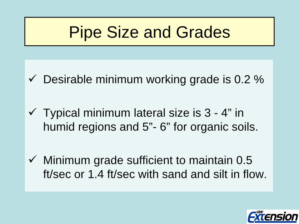
Pipe Size and Grades
Desirable minimum working grade is 0.2 %
Typical minimum lateral size is 3 - 4” in humid regions and 5”- 6” for organic soils.
Minimum grade sufficient to maintain 0.5
ft/sec or 1.4 ft/sec with sand and silt in flow.

Tile Drain Design Tools - Web Based -
www.extension.umn.edu/AgDrainage/online-calculator.html
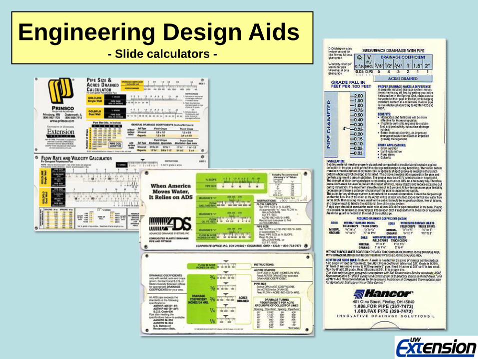
Engineering Design Aids - Slide calculators -

Tile System Maintenance
Rodent Guards Keep rodents from moving into tiles lines. Guards can sometimes plug so they need to be checked.
Photo from Eric Cooley, UW Discovery Farms

Tile System Design & Maintenance - Pipe Flow Velocity -
Very high velocities can cause “sink holes” when soil is actually pulled into the tile line.
“Blowouts” can occur when lines become pressurized.
Soil Texture
Max. Velocity
ft/sec Sand & sandy loam 3.5
Silt & silt Loam 5.0
Silty clay loam 6.0
Clay & Clay loam 7.0
Course sand or gravel 9.0
Watch out for steep-to-flat grade changes and overloading mains …. Blowouts !
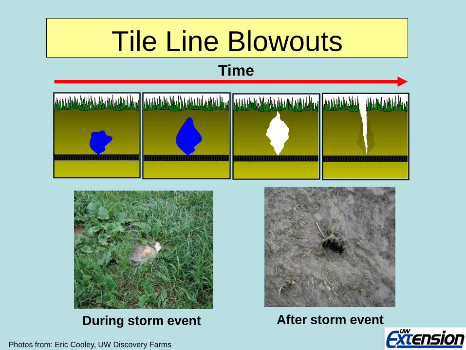
Tile Line Blowouts Time
During storm event After storm event
Photos from: Eric Cooley, UW Discovery Farms
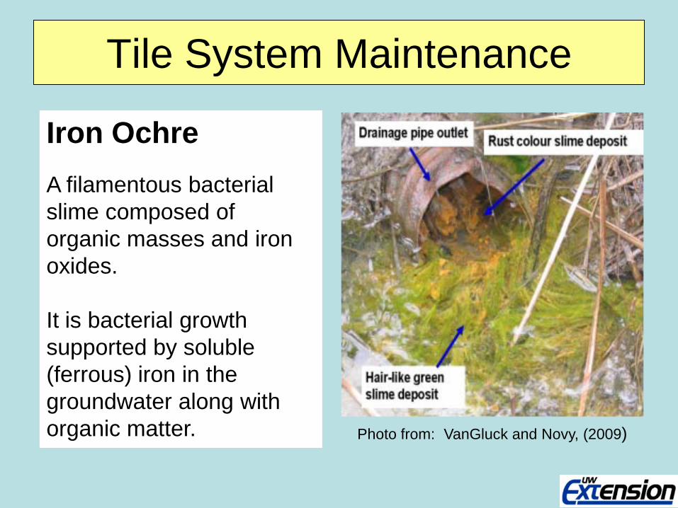
Tile System Maintenance
Iron Ochre A filamentous bacterial slime composed of organic masses and iron oxides. It is bacterial growth supported by soluble (ferrous) iron in the groundwater along with organic matter. Photo from: VanGluck and Novy, (2009)
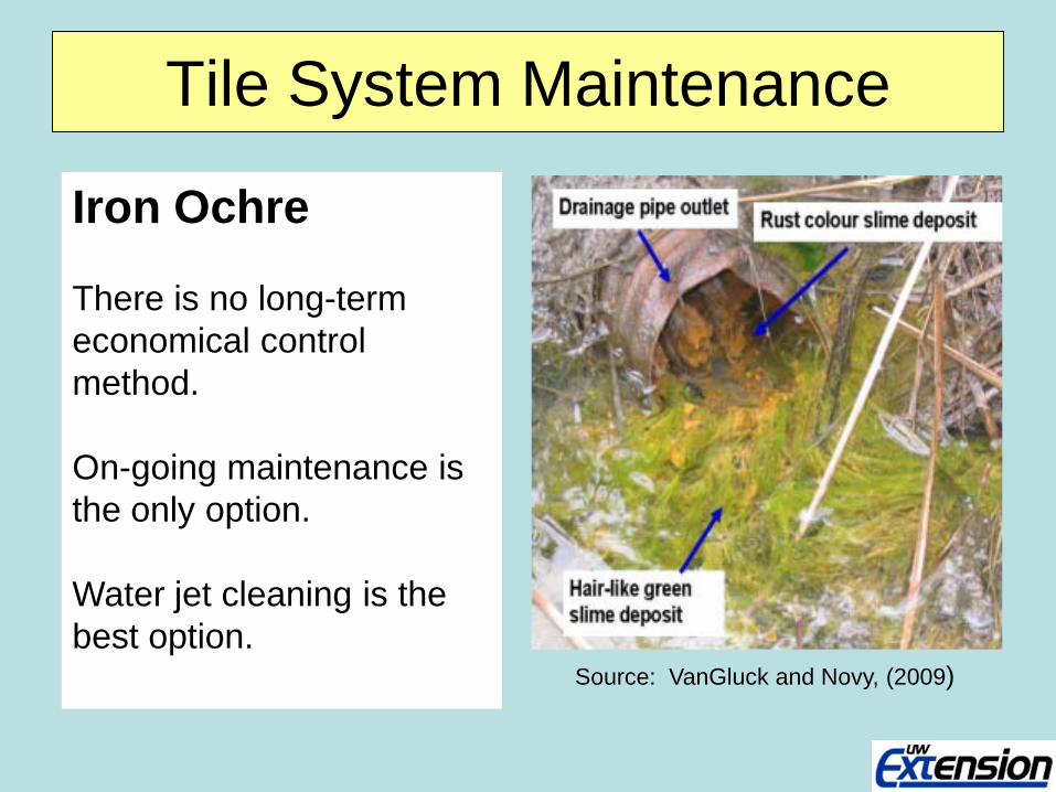
Tile System Maintenance
Iron Ochre There is no long-term economical control method. On-going maintenance is the only option. Water jet cleaning is the best option. Source: VanGluck and Novy, (2009)
UWEX Information Resources
UW Extension Tile Drainage Web Site http://fyi.uwex.edu/drainage/

UWEX Information Resources - Publications -
Tile Drainage in Wisconsin: Maintaining Tile Drainage Systems
Tile Drainage in Wisconsin: Understanding and Locating Tile Drainage Systems
learningstore.uwex.edu/
Drainage System Cost - Approximate ! -
Drainage system installation costs can vary significantly based on terrain, soils,
outlet availability, etc.
Rough Range ~ $1,000 – 1500 / ac
QUESTIONS ??