Embed Size (px)
Citation preview
www.projectiondesign.com
an introduc on to the MIPS processors, use, and set up
user’s guideMul
Image
Processing
System
Designed and manufactured in Fredrikstad, Norway.

en
glis
h
2MIPS User’s Guide – Introduction
This page intentionally left blank.

www.projectiondesign.com
en
glis
h
3
Introduction
Thank you
Thank you for purchasing a MIPS processor.
The MIPS WB2560 and WB1920 are state-of-the-art image processing engines for the
combination and setup of multiple projectors in order to create one, large, seamless image.
By combining multiple projectors, images with unprecedented resolution and fi delity can be
created.
The MIPS processors feature unique functionality and unmatched compatibility, and
are perfectly tailored to working with projectiondesign projectors for use in multi-image
environments.
Features
• Geometry correction
• Blending and overlap
• 2560x1600, and 1920x1200 models available
• User selectable algorithm setups
• 4x4 Lanczos scaling
• Bi-linear scaling
• B-cubic scaling
• Project onto any surface
• Zero, or near zero latency, depending on set up and confi guration
• 3D stereo compatible, up to 1920x1200 on WB2560, and 1280x800 on WB1920
• Patented Black Level Matching for uniform black levels
• Per-pixel Colour-, Uniformity-, and brightness matching
• 12-bit internal resolution
• Dual-Link DVI-D in / out
• All control through Ethernet
• Built-in power supply for easy power management in large racks
• Integrates seamlessly with projectiondesign ProNet MIPS software setup suite
• Rack mount, ½ width, 1U height
• Unlimited scalability and channel count
• Fully transparent to source, no special software or source requirements

en
glis
h
4MIPS User’s Guide – Introduction
Contents
Introduction 3Thank you 3
Features 3
SAFETY 9GENERAL WARNINGS 9
WEEE INFORMATION 9
WARNING ABOUT SUBSTANCES 10
What’s in the box? 11The MIPS processor comes with the following components: 11
Installation and setup 14System requirements 14
System overview 15
Network settings 15
Software 15
Mounting the MIPS processor in rack 16
Getting to know the GUI 18ProNet.site 18
MIPS Calibrator – Device View 19
Creating and saving a MIPS system setup project
Backing up and restoring calibration
Adding MIPS units to a project
Using the Device View Toolbar, DVT
Clearing calibration
Notifi cations and advanced network settings
Performing software upgrades
Controlling EDID information
MIPS calibrator – Calibration View 24
Using the Calibration View Toolbar (CVT)
Selecting/deselecting MIPS units
Using the Calibration Panel Toolbar (CPT)
MIPS operational states 27
Bypass states
Calibration state
Online state
Slideshow state
Auto state
www.projectiondesign.com
en
glis
h
5
Geometry correction 29Warping algorithms 29
Perspective
Mesh Warp Smythe
Mesh Warp Bezier
Warping user interface
Scaling fi lters 30
Lanczos fi lter
B-spline fi lter
C-spline fi lter
Linear interpolation fi lter
Working with the perspective algorithm 32
Working with the Mesh Smythe algorithm 33
Working with Mesh Bezier algorithm 34
Fine tuning control points 35
Edge blending 37Introduction 37
Edge blending algorithms 37
Basic edge blending
Advanced edge blending
User interface for basic edge blending
User interface for advanced edge blending
Adjusting the shape of advanced edge blending zones
Adjusting the blend drop-off curve
Test patterns 43Circle test pattern 44
Grid (Pixel) test pattern 45
Grid (Angle) test pattern 46
Turning test patterns on and off 46
Black Level Management 47Creating adjustment zones 47
Removing BLM zones 49
Adjusting black level in a defi ned zone 50
Masking 51Adding areas to clip 52
Removing clip areas 54
Storing and recalling data 56Storing/recalling calibration to/from the MIPS unit 56
Storing/recalling data to/from the control PC 57

en
glis
h
6MIPS User’s Guide – Introduction
Technical specifi cations 61Electrical 61
Mechanical 62
Environmental 63
Table of fi gures 65

www.projectiondesign.com
en
glis
h
7
Best practice
When setting up a MIPS based projection system, it is important to keep the following
guidelines in mind:
• A system is only as good as the weakest link - make sure cables, connectors, infrastructure and IG’s are top level.
• A system’s performance can almost always be improved – and there is no substitute for experience in, and knowledge about the components in it

en
glis
h
8MIPS User’s Guide - What’s in the Box?

www.projectiondesign.com
en
glis
h
9
SAFETY
This device complies with safety regulations for Information Technology Equipment intended
to operate in “normal” environments (offi ces and homes). Before using the device for the fi rst
time, please read the safety instructions thoroughly.
GENERAL WARNINGS
Use only the cables and cords supplied with the device or original replacement cables. Using
other cables or cords may lead to malfunction and permanent damage of the device.
Always use 3-prong / grounded power cord to ensure proper grounding of the device. Never
use 2-prong power cords, as this is dangerous and could lead to electrical shock.
Never open the device. The device contains no user serviceable parts. Refer all repairs to
qualifi ed personnel only. Make sure that no objects enter into the vents and openings of the
set.
Do not spill any liquids on the device or into the vents or openings of the device.
Always remove protective plastic covering the device before operating the device.
Only place the device on a stable surface, or mount it securely in a rack.
Do not drop the device.
The device can be used as desktop or rack mounted with the certifi cation labels facing
down. Any other mounting directions are not allowed. When rack mounted, care must be
taken to keep ventilation on back and front side open. Operating the device in other positions
may lead to overheating, resulting in malfunctioning.
Always allow ample airfl ow through the device. Never block any of the air vents. Never
cover the device in any way while running. Allow for suffi cient distance to walls and other
obstructions to avoid overheating.
Minimum safety distance to front or rear of the device is 20 cm (8”) to rear and 5 cm (2”) to
front.
The device is designed for indoor use only. Never operate the device outdoors.
Do not operate the device outside its temperature and humidity specifi cations, as this may
result in overheating and malfunctioning.
Only connect the device to signal sources and voltages as described in the technical
specifi cation. Connecting to unspecifi ed signal sources or voltages may lead to malfunction
and permanent damage of the device.
WEEE INFORMATION
This product conforms to all requirements of the EU Directive on waste electrical and
electronic equipment (WEEE). This product shall be recycled properly. It can be disassembled
to facilitate proper recycling of the individual parts.
Consult your dealer or relevant public authority regarding drop-off points for collection of
WEEE.

en
glis
h
10MIPS User’s Guide – Safety instructions
WARNING ABOUT SUBSTANCES
This product contains chemicals, including lead, known to the State of California to cause
birth defects or other reproductive harm. Recycle properly, do not dispose of in ordinary
waste!.
WARNING SYMBOLS
READ USER GUIDE Attention! Read the user guide for further information!
RECYCLE Warning! Recycle properly, do not dispose of in ordinary waste!
NO TELEPHONE Warning! Do not connect to telephone lines!
www.projectiondesign.com
en
glis
h
11
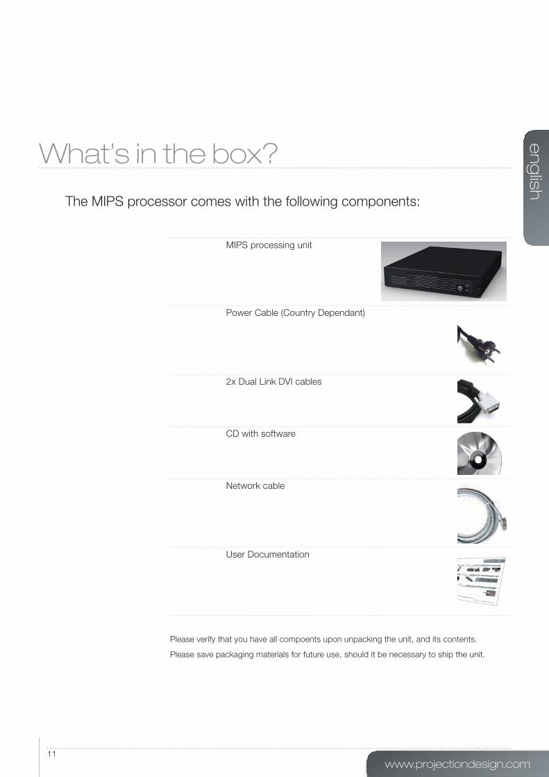
What’s in the box?
The MIPS processor comes with the following components:
MIPS processing unit
Power Cable (Country Dependant)
2x Dual Link DVI cables
CD with software
Network cable
User Documentation
Please verify that you have all compoents upon unpacking the unit, and its contents.
Please save packaging materials for future use, should it be necessary to ship the unit.


www.projectiondesign.com
en
glis
h
13
en
glis
h
14MIPS User’s Guide – Installation and setup
Installation and setup
The following section outlines the general requirements to supporting equipment in order to
run the MIPS plugin, and successfully setting up a MIPS based projection system.
System requirements
ProNet 2.0 – required to set up and operate MIPS processors, works with Microsoft
Windows® operating systems only. The following versions are supported:
• Windows XP (32-bit only), SP xx or
• Windows Vista (32- or 64-bit)
• Windows 7 (32- or 64-bit)
In addition, Microsoft .NET Framework 3.5 or later must be installed.
Any standard computer capable of running the above operating systems should work, but for
best performance, the computer running ProNet 2.0 should have at least:
• Intel® Dual Core™ architecture or similar.
• 2 GB of RAM
• 200 MB of free disk space
• 1.0 Gigabit Ethernet interface
NOTE! For the ProNet application to be displayed correctly, 96 DPI must be used (Windows
Default).
www.projectiondesign.com
en
glis
h
15
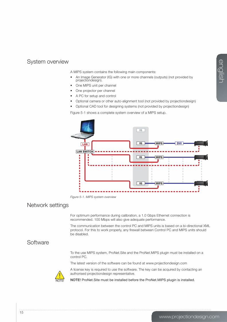
System overview
A MIPS system contains the following main components:
• An Image Generator (IG) with one or more channels (outputs) (not provided by projectiondesign).
• One MIPS unit per channel
• One projector per channel
• A PC for setup and control
• Optional camera or other auto-alignment tool (not provided by projectiondesign)
• Optional CAD tool for designing systems (not provided by projectiondesign)
Figure 5-1 shows a complete system overview of a MIPS setup.
Figure 5-1. MIPS system overview
Network settings
For optimum performance during calibration, a 1.0 Gbps Ethernet connection is
recommended. 100 Mbps will also give adequate performance.
The communication between the control PC and MIPS units is based on a bi-directional XML
protocol. For this to work properly, any fi rewall between Control PC and MIPS units should
be disabled.
Software
To the use MIPS system, ProNet.Site and the ProNet.MIPS plugin must be installed on a
control PC.
The latest version of the software can be found at www.projectiondesign.com
A license key is required to use the software. The key can be acquired by contacting an
authorised projectiondesign representative.
NOTE! ProNet.Site must be installed before the ProNet.MIPS plugin is installed.
en
glis
h
16MIPS User’s Guide – Installation and setup
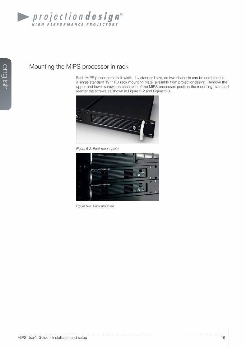
Mounting the MIPS processor in rack
Each MIPS processor is half-width, 1U standard size, so two channels can be combined in
a single standard 19” 1RU rack mounting plate, available from projectiondesign. Remove the
upper and lower screws on each side of the MIPS processor, position the mounting plate and
reenter the screws as shown in Figure 5-2 and Figure 5-3.
Figure 5-2. Rack mount plate
Figure 5-3. Rack mounted

www.projectiondesign.com
en
glis
h
17
en
glis
h
18MIPS User’s Guide – Getting to know the GUI
Getting to know the GUI
ProNet.site
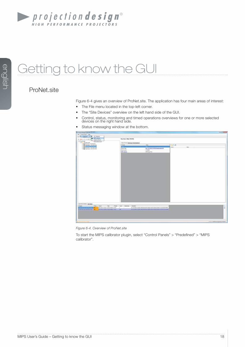
Figure 6-4 gives an overview of ProNet.site. The application has four main areas of interest:
• The File menu located in the top-left corner.
• The “Site Devices” overview on the left hand side of the GUI.
• Control, status, monitoring and timed operations overviews for one or more selected devices on the right hand side.
• Status messaging window at the bottom.
Figure 6-4. Overview of ProNet.site
To start the MIPS calibrator plugin, select “Control Panels” > “Predefi ned” > “MIPS
calibrator”.
www.projectiondesign.com
en
glis
h
19
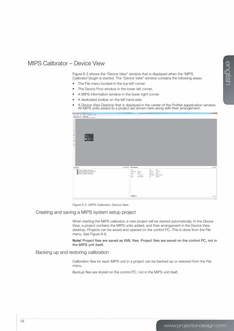
MIPS Calibrator – Device View
Figure 6-5 shows the “Device View” window that is displayed when the “MIPS
Calibrator”plugin is started. The “Device View” window contains the following areas:
• The File menu located in the top-left corner
• The Device Pool window in the lower left corner.
• A MIPS information window in the lower right corner.
• A dedicated toolbar on the left hand side.
• A Device View Desktop that is displayed in the center of the ProNet aapplication window. All MIPS units added to a project are shown here along with their arrangement.
Figure 6-5. MIPS Calibrator, Device View.
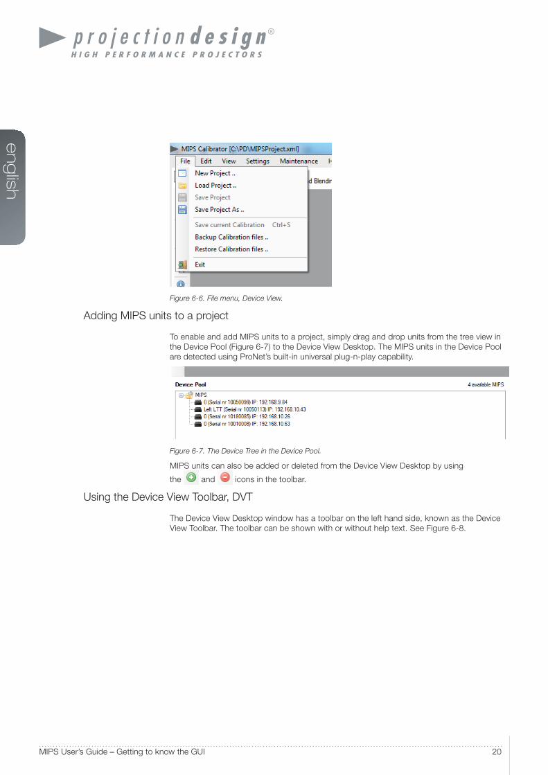
Creating and saving a MIPS system setup project
When starting the MIPS calibrator, a new project will be started automatically. In the Device
View, a project contains the MIPS units added, and their arrangement in the Device View
desktop. Projects can be saved and opened on the control PC. This is done from the File
menu. See Figure 6-6.
Note! Project fi les are saved as XML fi les. Project fi les are saved on the control PC, not in the MIPS unit itself.
Backing up and restoring calibration
Calibration fi les for each MIPS unit in a project can be backed up or restored from the File
menu.
Backup fi les are stored on the control PC, not in the MIPS unit itself.
en
glis
h
20MIPS User’s Guide – Getting to know the GUI
Figure 6-6. File menu, Device View.
Adding MIPS units to a project
To enable and add MIPS units to a project, simply drag and drop units from the tree view in
the Device Pool (Figure 6-7) to the Device View Desktop. The MIPS units in the Device Pool
are detected using ProNet’s built-in universal plug-n-play capability.
Figure 6-7. The Device Tree in the Device Pool.
MIPS units can also be added or deleted from the Device View Desktop by using
the and icons in the toolbar.
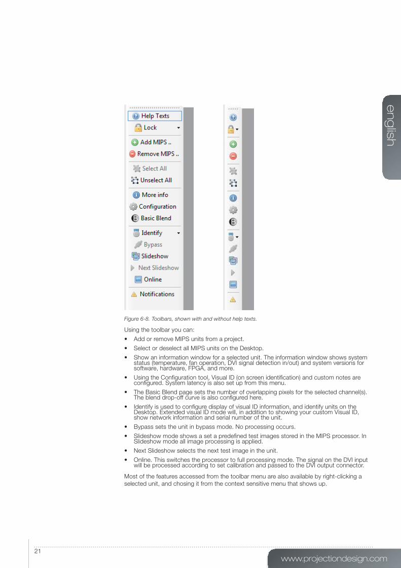
Using the Device View Toolbar, DVT
The Device View Desktop window has a toolbar on the left hand side, known as the Device
View Toolbar. The toolbar can be shown with or without help text. See Figure 6-8.
www.projectiondesign.com
en
glis
h
21
Figure 6-8. Toolbars, shown with and without help texts.
Using the toolbar you can:
• Add or remove MIPS units from a project.
• Select or deselect all MIPS units on the Desktop.
• Show an information window for a selected unit. The information window shows system status (temperature, fan operation, DVI signal detection in/out) and system versions for software, hardware, FPGA, and more.
• Using the Confi guration tool, Visual ID (on screen identifi cation) and custom notes are confi gured. System latency is also set up from this menu.
• The Basic Blend page sets the number of overlapping pixels for the selected channel(s). The blend drop-off curve is also confi gured here.
• Identify is used to confi gure display of visual ID information, and identify units on the Desktop. Extended visual ID mode will, in addition to showing your custom Visual ID, show network information and serial number of the unit.
• Bypass sets the unit in bypass mode. No processing occurs.
• Slideshow mode shows a set a predefi ned test images stored in the MIPS processor. In Slideshow mode all image processing is applied.
• Next Slideshow selects the next test image in the unit.
• Online. This switches the processor to full processing mode. The signal on the DVI input will be processed according to set calibration and passed to the DVI output connector.
Most of the features accessed from the toolbar menu are also available by right-clicking a
selected unit, and chosing it from the context sensitive menu that shows up.

en
glis
h
22MIPS User’s Guide – Getting to know the GUI
Clearing calibration
To clear calibration from selected MIPS units, select Edit > Clear Calibration from the File
menu. Under Clear Calibration, one can select to clear all or just parts of the calibration. See
Figure 6-9.
Figure 6-9. Clearing calibration
Notifi cations and advanced network settings
Under Settings > Application Settings, message notifi cation levels and advanced network
settings are confi gured, see Figure 6-10.
Figure 6-10. Application and Network settings.
www.projectiondesign.com
en
glis
h
23
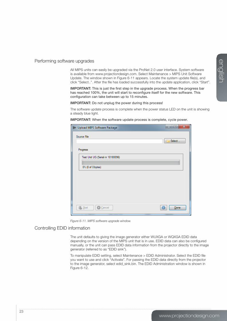
Performing software upgrades
All MIPS units can easily be upgraded via the ProNet 2.0 user interface. System software
is available from www.projectiondesign.com. Select Maintenance > MIPS Unit Software
Update. The window shown in Figure 6-11 appears. Locate the system update fi le(s), and
click “Select..”. After the fi le has loaded successfully into the update application, click “Start”.
IMPORTANT: This is just the fi rst step in the upgrade process. When the progress bar has reached 100%, the unit will start to reconfi gure itself for the new software. This confi guration can take between up to 15 minutes.
IMPORTANT: Do not unplug the power during this process!
The software update process is complete when the power status LED on the unit is showing
a steady blue light.
IMPORTANT: When the software update process is complete, cycle power.
Figure 6-11. MIPS software upgrade window.
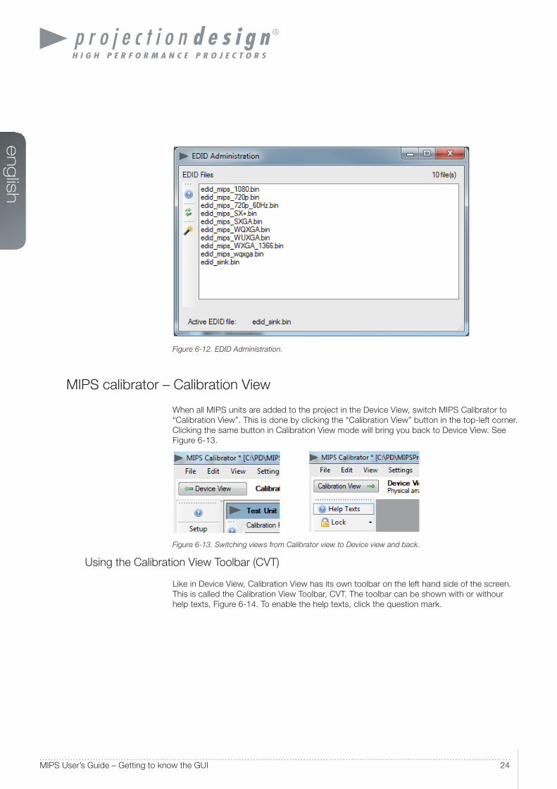
Controlling EDID information
The unit defaults to giving the image generator either WUXGA or WQXGA EDID data
depending on the version of the MIPS unit that is in use. EDID data can also be confi gured
manually, or the unit can pass EDID data information from the projector directly to the image
generator (referred to as “EDID sink”).
To manipulate EDID setting, select Maintenance > EDID Administrator. Select the EDID fi le
you want to use and click “Activate”. For passing the EDID data directly from the projector
to the image generator, select edid_sink.bin. The EDID Administration window is shown in
Figure 6-12.
en
glis
h
24MIPS User’s Guide – Getting to know the GUI
Figure 6-12. EDID Administration.
MIPS calibrator – Calibration View
When all MIPS units are added to the project in the Device View, switch MIPS Calibrator to
“Calibration View”. This is done by clicking the “Calibration View” button in the top-left corner.
Clicking the same button in Calibration View mode will bring you back to Device View. See
Figure 6-13.
Figure 6-13. Switching views from Calibrator view to Device view and back.
Using the Calibration View Toolbar (CVT)
Like in Device View, Calibration View has its own toolbar on the left hand side of the screen.
This is called the Calibration View Toolbar, CVT. The toolbar can be shown with or withour
help texts, Figure 6-14. To enable the help texts, click the question mark.
www.projectiondesign.com
en
glis
h
25
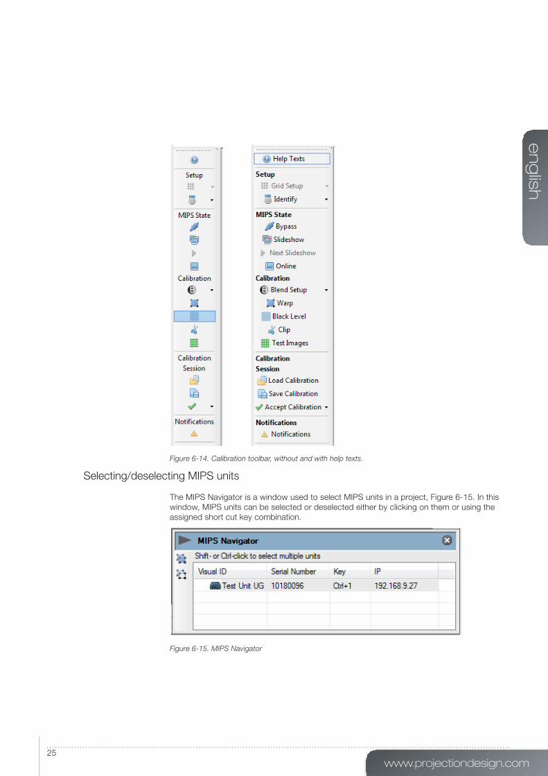
Figure 6-14. Calibration toolbar, without and with help texts.
Selecting/deselecting MIPS units
The MIPS Navigator is a window used to select MIPS units in a project, Figure 6-15. In this
window, MIPS units can be selected or deselected either by clicking on them or using the
assigned short cut key combination.
Figure 6-15. MIPS Navigator
en
glis
h
26MIPS User’s Guide – Getting to know the GUI
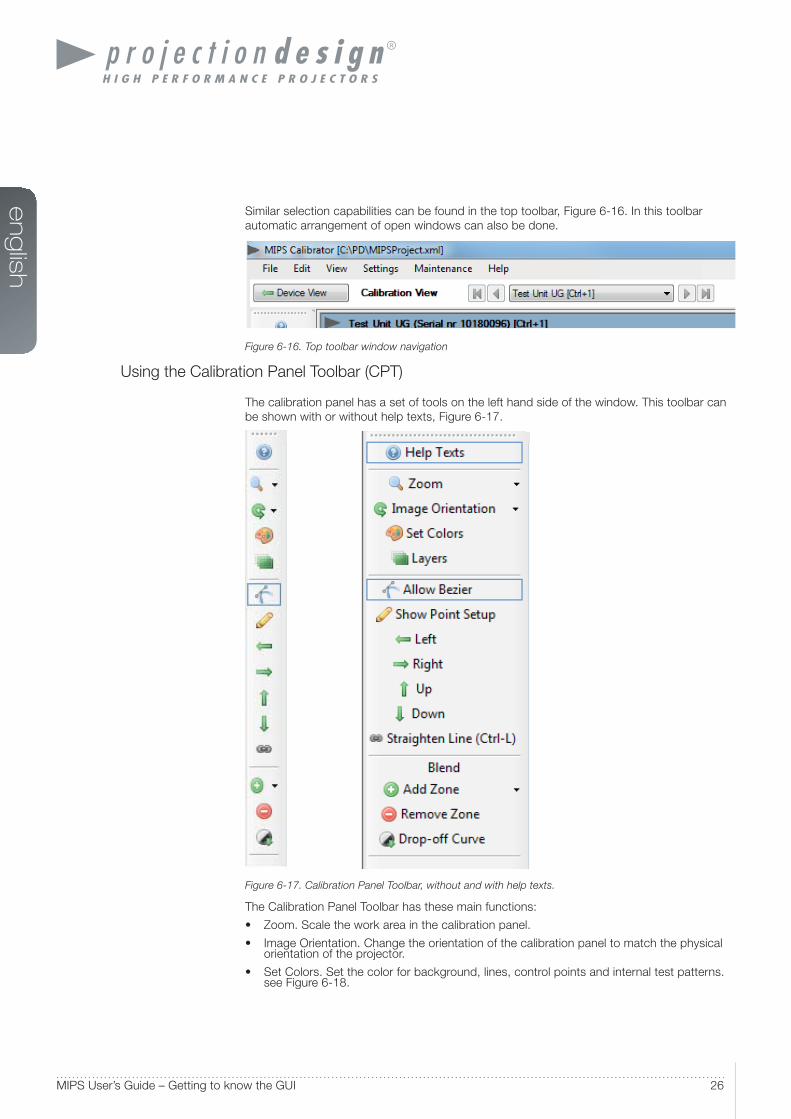
Similar selection capabilities can be found in the top toolbar, Figure 6-16. In this toolbar
automatic arrangement of open windows can also be done.
Figure 6-16. Top toolbar window navigation
Using the Calibration Panel Toolbar (CPT)
The calibration panel has a set of tools on the left hand side of the window. This toolbar can
be shown with or without help texts, Figure 6-17.
Figure 6-17. Calibration Panel Toolbar, without and with help texts.
The Calibration Panel Toolbar has these main functions:
• Zoom. Scale the work area in the calibration panel.
• Image Orientation. Change the orientation of the calibration panel to match the physical orientation of the projector.
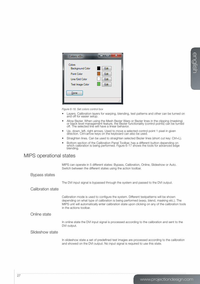
• Set Colors. Set the color for background, lines, control points and internal test patterns. see Figure 6-18.
www.projectiondesign.com
en
glis
h
27
Figure 6-18. Set colors control box
• Layers. Calibration layers for warping, blending, test patterns and other can be turned on and off for easier setup.
• Allow Bezier. When using the Mesh Bezier Warp or Bezier lines in the clipping (masking) or black level management feature, the Bezier functionality (control points) can be turned off. The selected line will have a linear behavior.
• Up, down, left, right arrows. Used to move a selected control point 1 pixel in given direction. Ctrl+arrow keys on the keyboard can also be used.
• Straighten lines. Can be used to straighten selected Bezier lines (short cut key: Ctrl+L).
• Bottom section of the Calibration Panel Toolbar, has a different button depending on which calibration is being performed. Figure 6-17 shows the tools for advanced edge blending.
MIPS operational states
MIPS can operate in 5 different states: Bypass, Calibration, Online, Slideshow or Auto.
Switch between the different states using the action toolbar.
Bypass states
The DVI input signal is bypassed through the system and passed to the DVI output.
Calibration state
Calibration mode is used to confi gure the system. Different testpatterns will be shown
depending on what type of calibration is being performed (warp, blend, masking etc.). The
MIPS unit will automatically enter calibration state upon clicking on any of the calibration tools
in the actions toolbar.
Online state
In online state the DVI input signal is processed according to the calibration and sent to the
DVI output.
Slideshow state
In slideshow state a set of predefi ned test images are processed according to the calibration
and showed on the DVI output. No input signal is required to use this state.

en
glis
h
28MIPS User’s Guide – Getting to know the GUI
Auto state
When a calibration is completed and the accepted calibration is stored in MIPS unit auto
state will be used upon power up of the unit. If the MIPS fi nd a stored calibration that
matches the input resolution, the online will enter online state (image processing enabled). If
no calibration is found, the unit will be in bypass state.

www.projectiondesign.com
en
glis
h
29
Geometry correction
Image Geometry Correction (often referred to as Image Warping) is the process of digitally
manipulating image data so that the image’s projection precisely matches a specifi c
projection surface or shape. Image Geometry Correction compensates for the distortion
created by off-axis projector or screen placement or non-fl at screen surfaces by applying a
compensating inverse distortion to the image in the digital domain. Usually, Image Geometry
Correction is applied so that areas of the projection surface are perceived by the viewer to
map to the corresponding areas in the source image.
Warping algorithms
The MIPS system is supporting 3 different warping algorithms: Perspective, Mesh Warp
Smythe, Mesh Warp Bezier. The best way to understand how they work is to test the
different algorithms in an actual system setup. One projector and one MIPS unit is enough to
learn how they work.
Note! Image Geometry Correction is not applied until operational mode is changed to “online”.
Perspective
This is advanced keystone. Only the four corners of the image can be manipulated.
Mesh Warp Smythe
This is recommended for use on simple, maybe slightly curved screens. Number of control
points can be dynamically added. Start off with a few control points and increase the grid
size as needed. When the grid is increased, the position of any added point in the fi ner grid
mask will be given a correct position automatically. Max grid size is 16x16.
Mesh Warp Bezier
This is a very powerful tool where you can manipulate not only the control points of the grid,
but also the tangent vectors connected to every control point. The control points of the
tangent vectors are called Bezier control points.
Bezier patch meshes are superior to meshes of triangles as a representation of smooth
surfaces, since they are much more compact, easier to manipulate, and have much better
continuity properties. In addition, other common parametric surfaces such as spheres and
cylinders can be well approximated by relatively small numbers of cubic Bezier patches.
Max grid size is 16x16, but the fl exibility of this algorithm usually allows for correct geometric
distortion with very few control points.
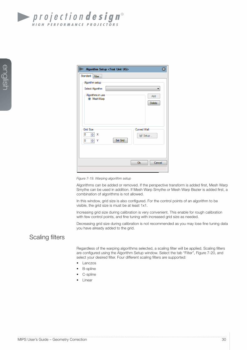
Warping user interface
To apply warping to an image, select “ Warp” from the left hand toolbar. The window in Figure
7-19 will appear.
en
glis
h
30MIPS User’s Guide – Geometry Correction
Figure 7-19. Warping algorithm setup
Algorithms can be added or removed. If the perspective transform is added fi rst, Mesh Warp
Smythe can be used in addition. If Mesh Warp Smythe or Mesh Warp Bezier is added fi rst, a
combination of algorithms is not allowed.
In this window, grid size is also confi gured. For the control points of an algorithm to be
visible, the grid size is must be at least 1x1.
Increasing grid size during calibration is very convenient. This enable for rough calibration
with few control points, and fi ne tuning with increased grid size as needed.
Decreasing grid size during calibration is not recommended as you may lose fi ne tuning data
you have already added to the grid.
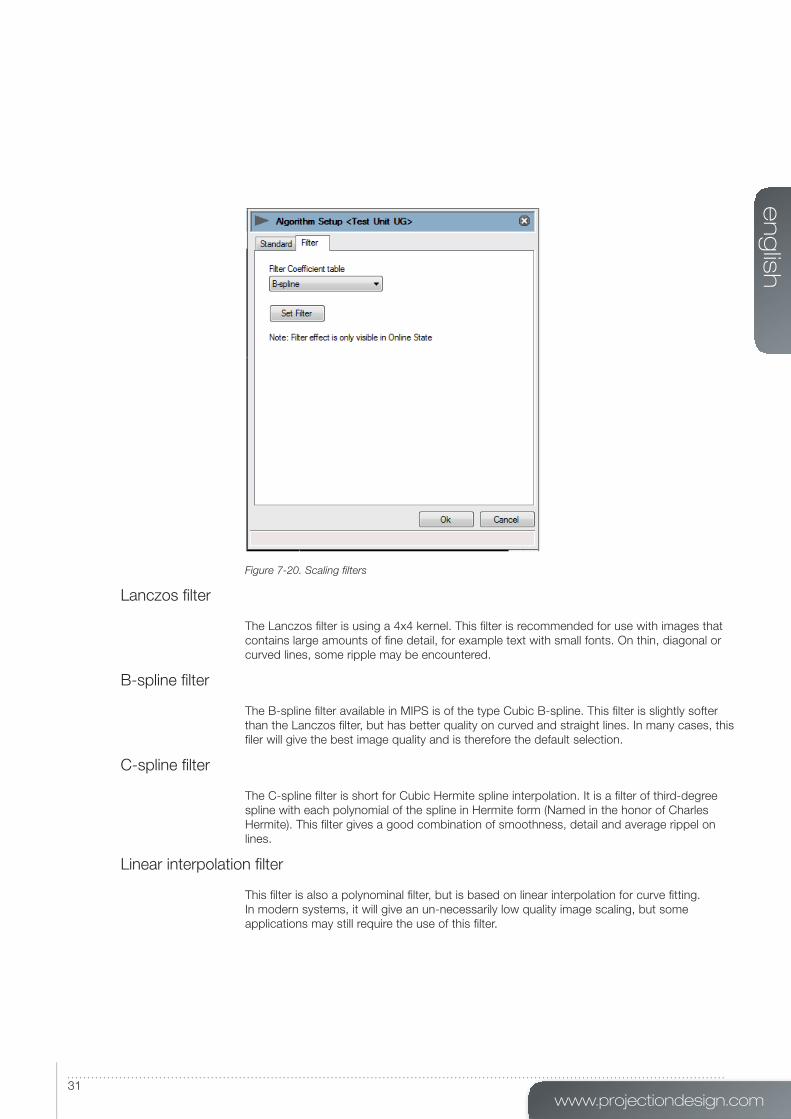
Scaling fi lters
Regardless of the warping algorithms selected, a scaling fi lter will be applied. Scaling fi lters
are confi gured using the Algorithm Setup window. Select the tab “Filter”, Figure 7-20, and
select your desired fi lter. Four different scaling fi lters are supported:
• Lanczos
• B-spline
• C-spline
• Linear
www.projectiondesign.com
en
glis
h
31
Figure 7-20. Scaling filters
Lanczos fi lter
The Lanczos fi lter is using a 4x4 kernel. This fi lter is recommended for use with images that
contains large amounts of fi ne detail, for example text with small fonts. On thin, diagonal or
curved lines, some ripple may be encountered.
B-spline fi lter
The B-spline fi lter available in MIPS is of the type Cubic B-spline. This fi lter is slightly softer
than the Lanczos fi lter, but has better quality on curved and straight lines. In many cases, this
fi ler will give the best image quality and is therefore the default selection.
C-spline fi lter
The C-spline fi lter is short for Cubic Hermite spline interpolation. It is a fi lter of third-degree
spline with each polynomial of the spline in Hermite form (Named in the honor of Charles
Hermite). This fi lter gives a good combination of smoothness, detail and average rippel on
lines.
Linear interpolation fi lter
This fi lter is also a polynominal fi lter, but is based on linear interpolation for curve fi tting.
In modern systems, it will give an un-necessarily low quality image scaling, but some
applications may still require the use of this fi lter.

en
glis
h
32MIPS User’s Guide – Geometry Correction
Working with the perspective algorithm
To start working with the perspective algorithm, click the “ Warp” icon, add the perspective
algorithm and set grid size to 1x1. To map the geometry to the surface being projected on by
draging the control points with the mouse. Figure 7-21 shows basic usage of the Perspective
algorithm.
Figure 7-21. Working with the perspective transform
www.projectiondesign.com
en
glis
h
33
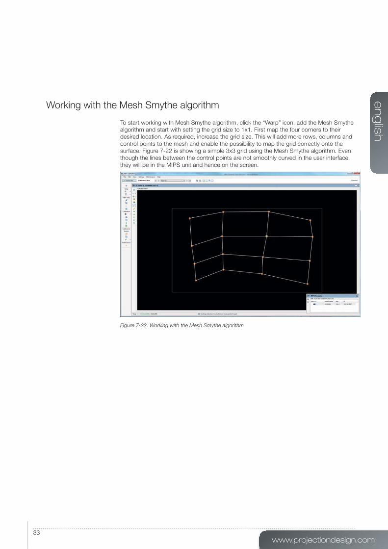
Working with the Mesh Smythe algorithm
To start working with Mesh Smythe algorithm, click the “ Warp” icon, add the Mesh Smythe
algorithm and start with setting the grid size to 1x1. First map the four corners to their
desired location. As required, increase the grid size. This will add more rows, columns and
control points to the mesh and enable the possibility to map the grid correctly onto the
surface. Figure 7-22 is showing a simple 3x3 grid using the Mesh Smythe algorithm. Even
though the lines between the control points are not smoothly curved in the user interface,
they will be in the MIPS unit and hence on the screen.
Figure 7-22. Working with the Mesh Smythe algorithm

en
glis
h
34MIPS User’s Guide – Geometry Correction
Working with Mesh Bezier algorithm
To start working with Mesh Bezier algorithm, click the “ Warp” icon, add the Mesh Bezier
algorithm and start with setting the grid size to 1x1. The grid you see now will contain four
control points – one in each corner. In addition all control point will have 2-4 additional, white
control points for controlling the Bezier vectors in a given point, Figure 7-23.
Figure 7-23. Mesh Bezier with 1x1 grid
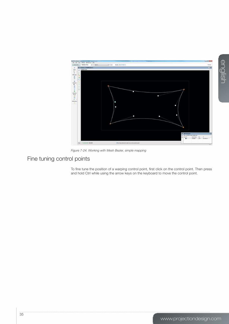
First map the four control points (orange) to their desired location. Then move the Bezier
control point to curve the lines between to control points to map the screen geometry
(Figure 7-24). When using this algorithm, geometry mapping to cylinders, spheres and other
well defi ned surfaces can be done with very few control points. Like with the Mesh Smythe
algorithms, the grid size can be increased as much as needed to get the required accuracy
for a given surface. A 1x1 grid should regardless of the projection surface be used as a
starting point.
www.projectiondesign.com
en
glis
h
35
Figure 7-24. Working with Mesh Bezier, simple mapping
Fine tuning control points
To fi ne tune the position of a warping control point, fi rst click on the control point. Then press
and hold Ctrl while using the arrow keys on the keyboard to move the control point.


www.projectiondesign.com
en
glis
h
37
Edge blending
Introduction
Edge Blending is a companion feature to Image Geometry Correction. Edge Blending
enables the seamless projection of a large image using several overlapping projectors. Since
geometry correction for projection on non-fl at surfaces is a built-in requirement in almost all
Edge Blending systems, the pairing of Edge Blending and Image Geometry Correction in the
same video signal processor is a natural one.
Edge blending algorithms
MIPS support two different types of edge blending: Basic and Advanced
Basic edge blending
Basic edge blending is used for simple and slightly curved surfaces. A percentage or a
defi ned number of overlapping pixels is specifi ed. The overlapping region of each side (top,
bottom, left, right) of the image is then geometry corrected with the warping that is being
applied to the image.
Advanced edge blending
Advanced edge blending is used for more complex surfaces like a dome (spherical). With
advanced edge blending, warping and blending is completely disconnected. After correct
geometry correction has been applied, multiple blend areas are defi ned to create the
seamless image.
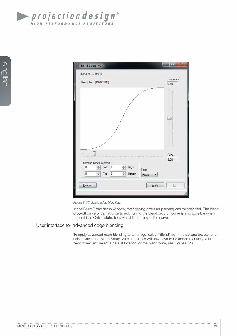
User interface for basic edge blending
To apply basic edge blending to an image, select “Blend” from the left hand toolbar, and
select Basic Blend Setup. The window in Figure 8-25 will appear.
en
glis
h
38MIPS User’s Guide – Edge Blending
Figure 8-25. Basic edge blending.
In the Basic Blend setup window, overlapping pixels (or percent) can be specifi ed. The blend
drop-off curve of can also be tuned. Tuning the blend drop off curve is also possible when
the unit is in Online state, for a visual fi ne tuning of the curve.
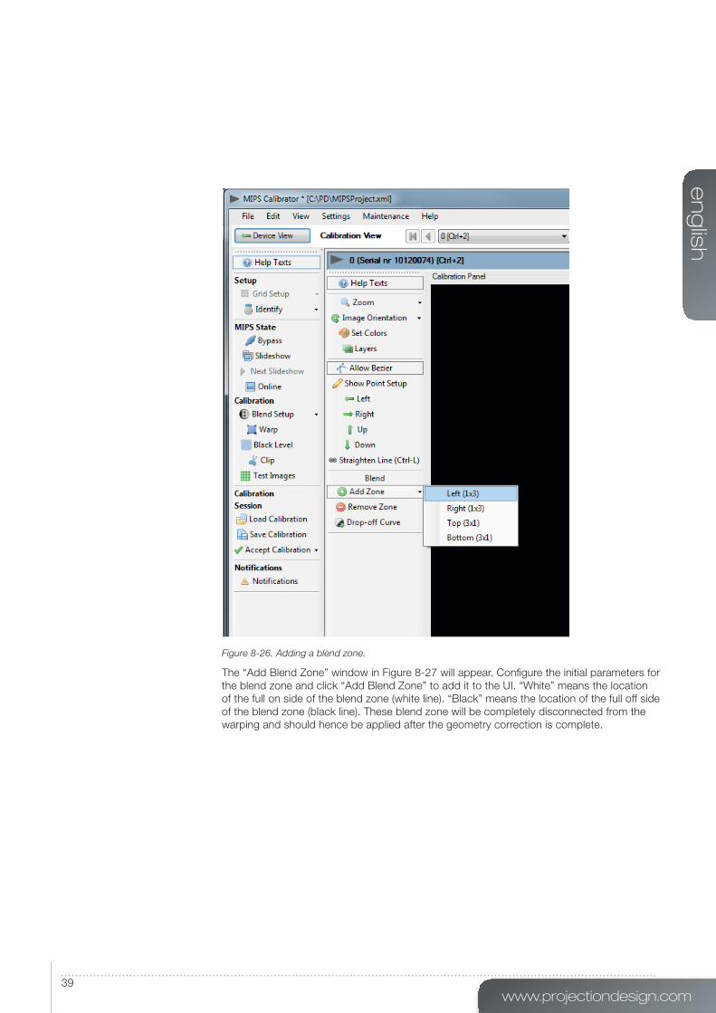
User interface for advanced edge blending
To apply advanced edge blending to an image, select “Blend” from the actions toolbar, and
select Advanced Blend Setup. All blend zones will now have to be added manually. Click
“Add zone” and select a default location for the blend zone, see Figure 8-26.
www.projectiondesign.com
en
glis
h
39
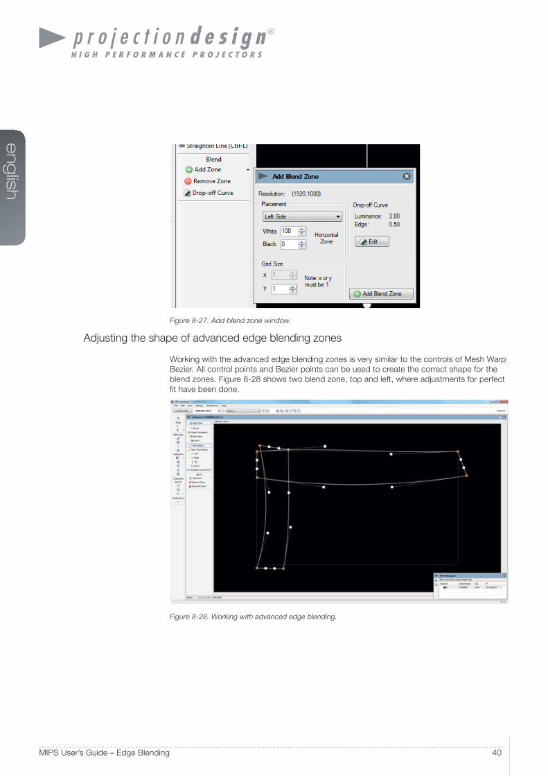
Figure 8-26. Adding a blend zone.
The “Add Blend Zone” window in Figure 8-27 will appear. Confi gure the initial parameters for
the blend zone and click “Add Blend Zone” to add it to the UI. “White” means the location
of the full on side of the blend zone (white line). “Black” means the location of the full off side
of the blend zone (black line). These blend zone will be completely disconnected from the
warping and should hence be applied after the geometry correction is complete.
en
glis
h
40MIPS User’s Guide – Edge Blending
Figure 8-27. Add blend zone window.
Adjusting the shape of advanced edge blending zones
Working with the advanced edge blending zones is very similar to the controls of Mesh Warp
Bezier. All control points and Bezier points can be used to create the correct shape for the
blend zones. Figure 8-28 shows two blend zone, top and left, where adjustments for perfect
fi t have been done.
Figure 8-28. Working with advanced edge blending.
www.projectiondesign.com
en
glis
h
41
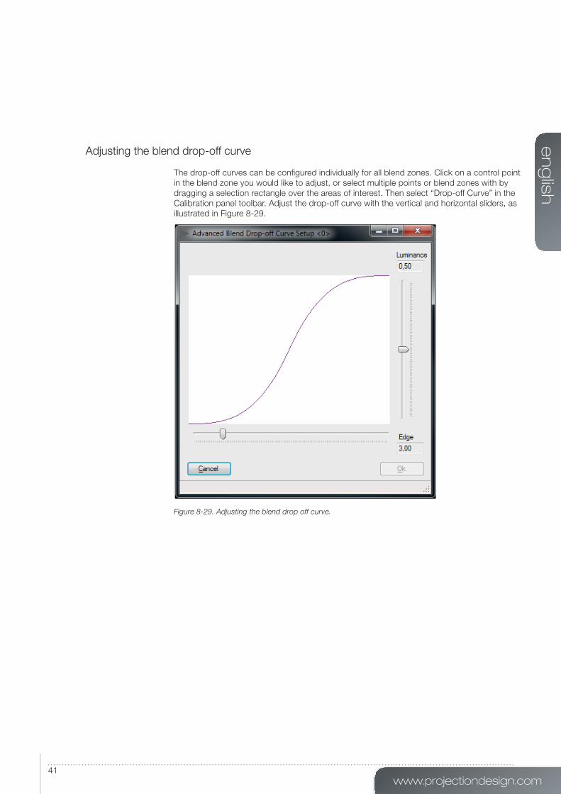
Adjusting the blend drop-off curve
The drop-off curves can be confi gured individually for all blend zones. Click on a control point
in the blend zone you would like to adjust, or select multiple points or blend zones with by
dragging a selection rectangle over the areas of interest. Then select “Drop-off Curve” in the
Calibration panel toolbar. Adjust the drop-off curve with the vertical and horizontal sliders, as
illustrated in Figure 8-29.
Figure 8-29. Adjusting the blend drop off curve.

www.projectiondesign.com
en
glis
h
43
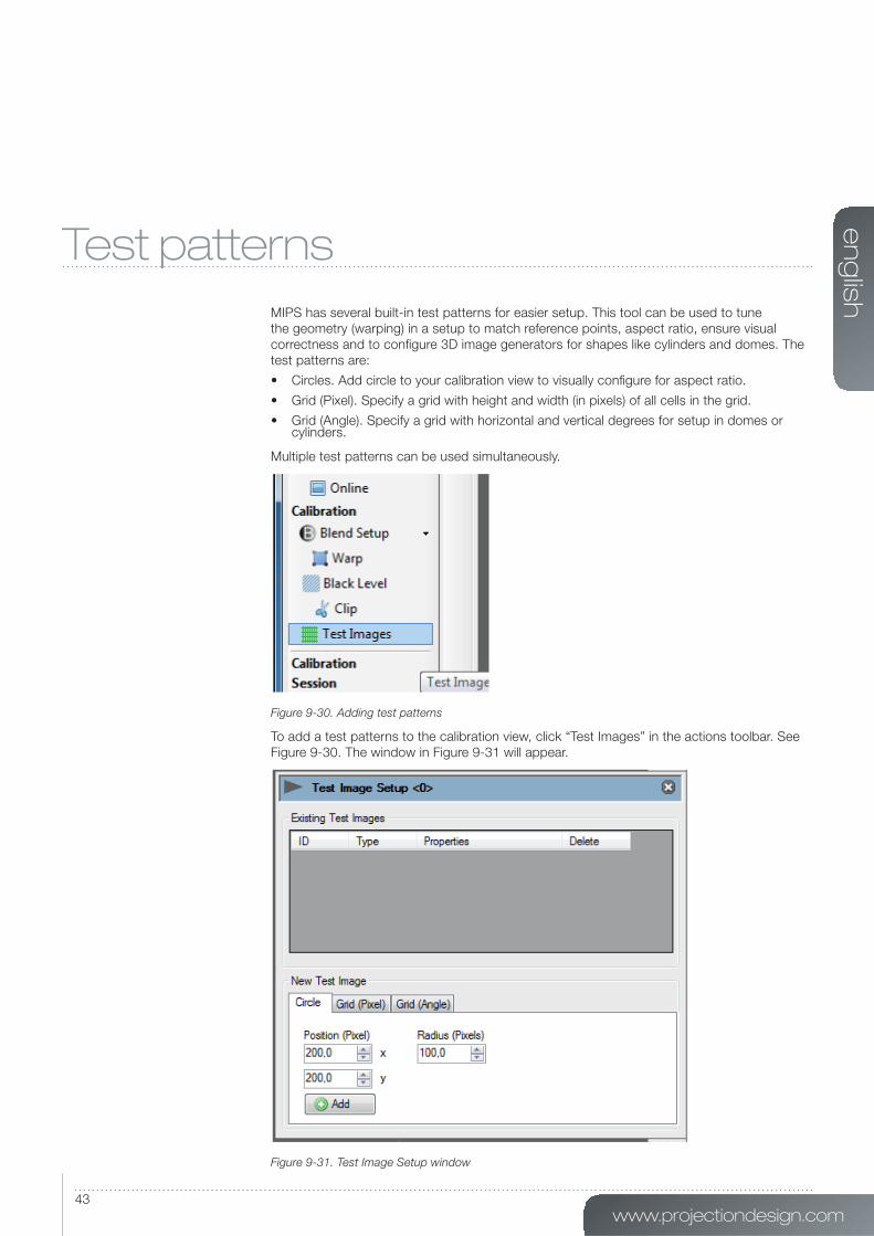
Test patterns
MIPS has several built-in test patterns for easier setup. This tool can be used to tune
the geometry (warping) in a setup to match reference points, aspect ratio, ensure visual
correctness and to confi gure 3D image generators for shapes like cylinders and domes. The
test patterns are:
• Circles. Add circle to your calibration view to visually confi gure for aspect ratio.
• Grid (Pixel). Specify a grid with height and width (in pixels) of all cells in the grid.
• Grid (Angle). Specify a grid with horizontal and vertical degrees for setup in domes or cylinders.
Multiple test patterns can be used simultaneously.
Figure 9-30. Adding test patterns
To add a test patterns to the calibration view, click “Test Images” in the actions toolbar. See
Figure 9-30. The window in Figure 9-31 will appear.
Figure 9-31. Test Image Setup window
en
glis
h
44MIPS User’s Guide – Test patterns
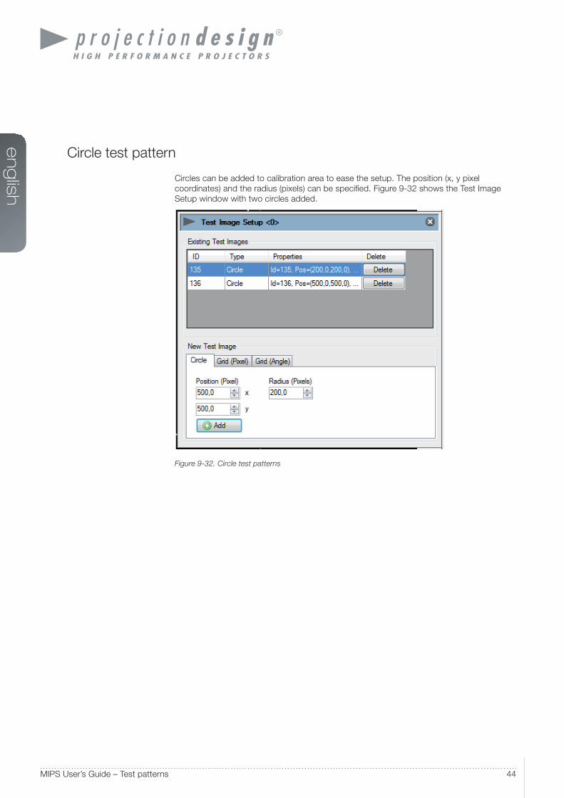
Circle test pattern
Circles can be added to calibration area to ease the setup. The position (x, y pixel
coordinates) and the radius (pixels) can be specifi ed. Figure 9-32 shows the Test Image
Setup window with two circles added.
Figure 9-32. Circle test patterns
www.projectiondesign.com
en
glis
h
45
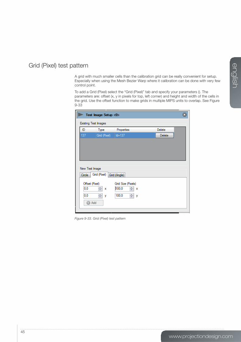
Grid (Pixel) test pattern
A grid with much smaller cells than the calibration grid can be really convenient for setup.
Especially when using the Mesh Bezier Warp where it calibration can be done with very few
control point.
To add a Grid (Pixel) select the “Grid (Pixel)” tab and specify your parameters (). The
parameters are: offset (x, y in pixels for top, left corner) and height and width of the cells in
the grid. Use the offset function to make grids in multiple MIPS units to overlap. See Figure
9-33
Figure 9-33. Grid (Pixel) test pattern
en
glis
h
46MIPS User’s Guide – Test patterns
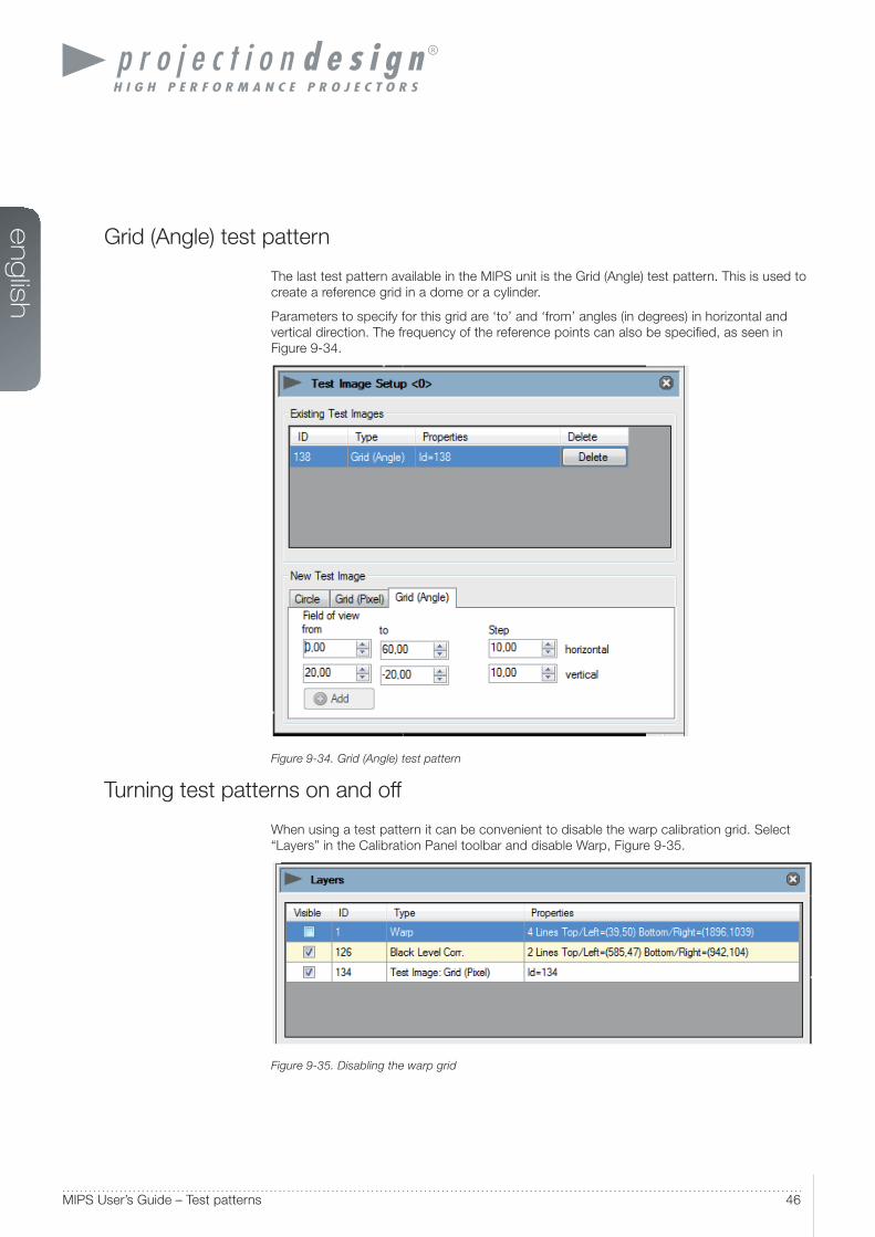
Grid (Angle) test pattern
The last test pattern available in the MIPS unit is the Grid (Angle) test pattern. This is used to
create a reference grid in a dome or a cylinder.
Parameters to specify for this grid are ‘to’ and ‘from’ angles (in degrees) in horizontal and
vertical direction. The frequency of the reference points can also be specifi ed, as seen in
Figure 9-34.
Figure 9-34. Grid (Angle) test pattern
Turning test patterns on and off
When using a test pattern it can be convenient to disable the warp calibration grid. Select
“Layers” in the Calibration Panel toolbar and disable Warp, Figure 9-35.
Figure 9-35. Disabling the warp grid
www.projectiondesign.com
en
glis
h
47
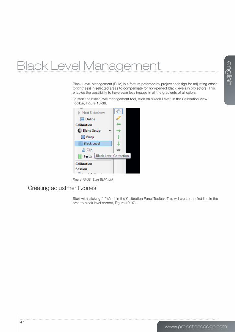
Black Level Management
Black Level Management (BLM) is a feature patented by projectiondesign for adjusting offset
(brightness) in selected areas to compensate for non-perfect black levels in projectors. This
enables the possibility to have seamless images in all the gradients of all colors.
To start the black level management tool, click on “Black Level” in the Calibration View
Toolbar, Figure 10-36.
Figure 10-36. Start BLM tool.
Creating adjustment zones
Start with clicking “+” (Add) in the Calibration Panel Toolbar. This will create the fi rst line in the
area to black level correct, Figure 10-37.

en
glis
h
48MIPS User’s Guide – Black Level Management
Figure 10-37. Adding Black Level Management lines.
Figure 10-38. Multiple Black Level Management lines added.

www.projectiondesign.com
en
glis
h
49
To create the next side in the zone, click on one of the control points in the fi rst line created
(not the Bezier points) and then click “+” (Add) again (Figure 10-38). This will add other line to
the calibration panel. Continue to add lines as needed. All these lines have the same controls
as Bezier lines in the Mesh Bezier Warp and the Advanced Edge Blending.
Figure 10-39. Connecting the first and last Black Level Management points.
Important! To add the last line connecting the fi rst and last control point, it is important select
both of the control points required to encapsulate the calibration area (Figure 10-39). To
select multiple points, either press and hold Ctrl while using the mouse point to select points
or drag and drop a selection rectangle over the points. Finally click “+” (Add) again to add the
last line.
Removing BLM zones
To remove a BLM zone, select a complete zone by performing a drag and drop selection
over a given zone. Individual points can also be select by pressing and holding Ctrl while
selecting with mouse pointer.
Click “Remove” in the Calibration Panel Toolbar to remove the zone(s) selected. Individual
lines in a zone can also be selected and removed.
en
glis
h
50MIPS User’s Guide – Black Level Management
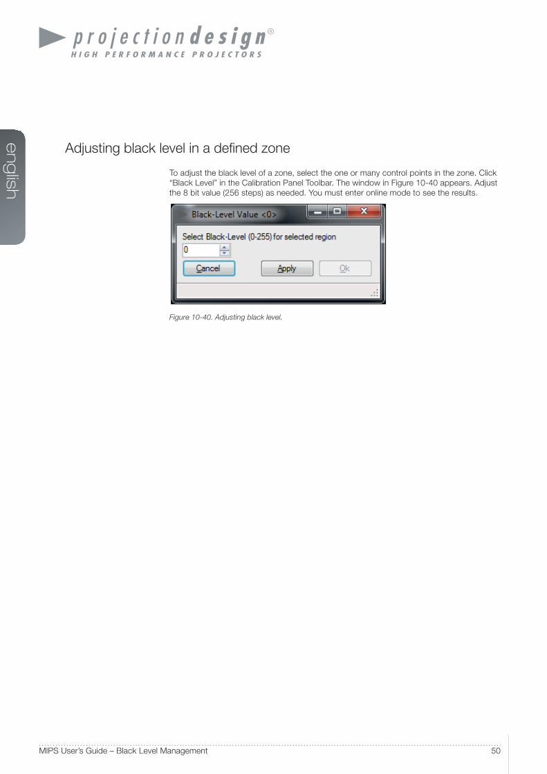
Adjusting black level in a defi ned zone
To adjust the black level of a zone, select the one or many control points in the zone. Click
“Black Level” in the Calibration Panel Toolbar. The window in Figure 10-40 appears. Adjust
the 8 bit value (256 steps) as needed. You must enter online mode to see the results.
Figure 10-40. Adjusting black level.
www.projectiondesign.com
en
glis
h
51
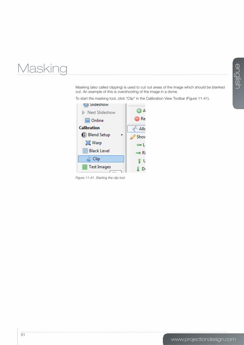
Masking
Masking (also called clipping) is used to cut out areas of the image which should be blanked
out. An example of this is overshooting of the image in a dome.
To start the masking tool, click “Clip” in the Calibration View Toolbar (Figure 11-41).
Figure 11-41. Starting the clip tool
en
glis
h
52MIPS User’s Guide – Masking
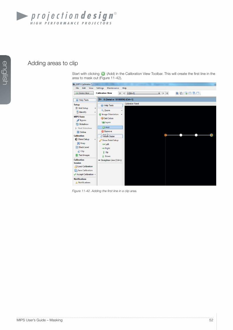
Adding areas to clip
Start with clicking (Add) in the Calibration View Toolbar. This will create the fi rst line in the
area to mask out (Figure 11-42).
Figure 11-42. Adding the first line in a clip area.
www.projectiondesign.com
en
glis
h
53
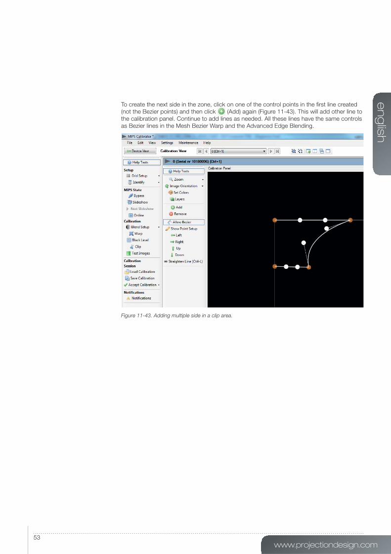
To create the next side in the zone, click on one of the control points in the fi rst line created
(not the Bezier points) and then click (Add) again (Figure 11-43). This will add other line to
the calibration panel. Continue to add lines as needed. All these lines have the same controls
as Bezier lines in the Mesh Bezier Warp and the Advanced Edge Blending.
Figure 11-43. Adding multiple side in a clip area.

en
glis
h
54MIPS User’s Guide – Masking
Note! To add the last line connecting the fi rst and last control point, it is important select both of the control points required to encapsulate the calibration area (Figure 11-44). To select multiple points, either press and hold Ctrl while using the mouse point to select points or drag and drop a selection rectangle over the points. Finally click (Add) again to add the last line.
Figure 11-44. Clipping area complete.
Finally, go to online mode to see the results.
Removing clip areas
To remove a masked (clipped) area, select a complete area by performing a drag and drop
selection over a given area. Individual points can also be select by pressing and holding Ctrl
while selecting with mouse pointer.
Click “Remove” in the Calibration Panel Toolbar to remove the area(s) selected. Individual
lines in an area can also be selected and removed.

www.projectiondesign.com
en
glis
h
55

en
glis
h
56MIPS User’s Guide – Storing and recalling data
Storing and recalling data
The MIPS system has powerful and fl exible features for storing and recalling calibration data.
When a calibration is a stored, the user can recall all calibration parameters at any given time
or on any given control PC. Calibration can be stored:
• In the MIPS unit.
• On the control PC. This is a copy of the data stored in the MIPS unit.
• Both.
Storing/recalling calibration to/from the MIPS unit
When storing calibration to the MIPS unit, it will be saved in the internal memory of the unit.
Should the MIPS unit or the control PC loose power during calibration, the data can easily
be recalled. To save the calibration to the MIPS unit click “Save Calibration” in the Calibration
view toolbar, press Ctrl+S or select “Save Calibration” from the fi le menu (Figure 12-45). Any
calibration already stored in the MIPS unit will be overwritten.
www.projectiondesign.com
en
glis
h
57
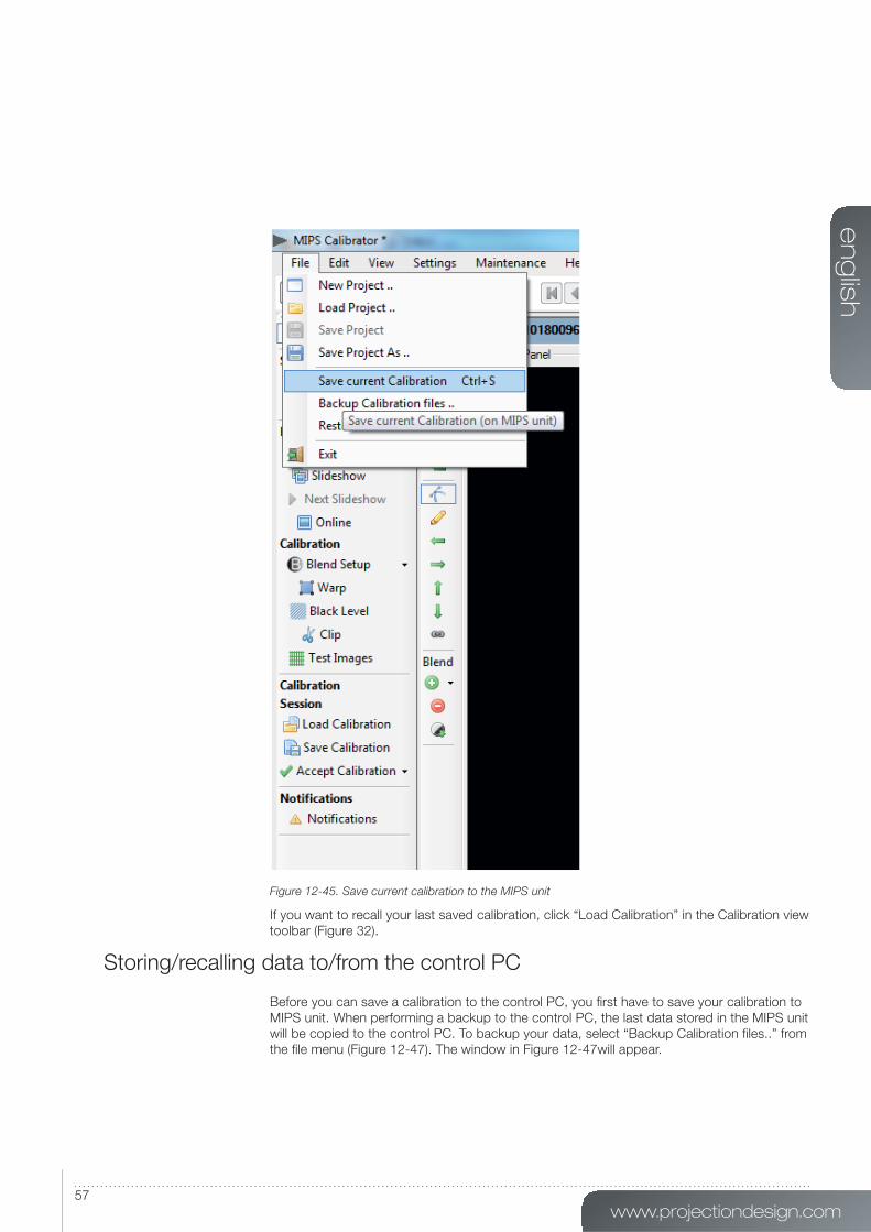
Figure 12-45. Save current calibration to the MIPS unit
If you want to recall your last saved calibration, click “Load Calibration” in the Calibration view
toolbar (Figure 32).
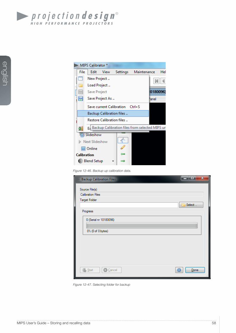
Storing/recalling data to/from the control PC
Before you can save a calibration to the control PC, you fi rst have to save your calibration to
MIPS unit. When performing a backup to the control PC, the last data stored in the MIPS unit
will be copied to the control PC. To backup your data, select “Backup Calibration fi les..” from
the fi le menu (Figure 12-47). The window in Figure 12-47will appear.
en
glis
h
58MIPS User’s Guide – Storing and recalling data
Figure 12-46. Backup up calibration data.
Figure 12-47. Selecting folder for backup
www.projectiondesign.com
en
glis
h
59
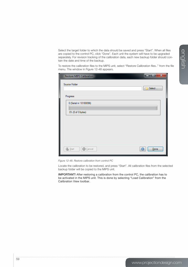
Select the target folder to which the data should be saved and press “Start”. When all fi les
are copied to the control PC, click “Done”. Each unit the system will have to be upgraded
separately. For revision tracking of the calibration data, each new backup folder should con-
tain the date and time of the backup.
To restore the calibration fi les to the MIPS unit, select “Restore Calibration fi les..” from the fi le
menu. The window in Figure 12-48 appears.
Figure 12-48. Restore calibration from control PC
Locate the calibration to be restored, and press “Start”. All calibration fi les from the selected
backup folder will be copied to the MIPS unit.
IMPORTANT! After restoring a calibration from the control PC, the calibration has to be activated in the MIPS unit. This is done by selecting “Load Calibration” from the Calibration View toolbar.

www.projectiondesign.com
en
glis
h
61
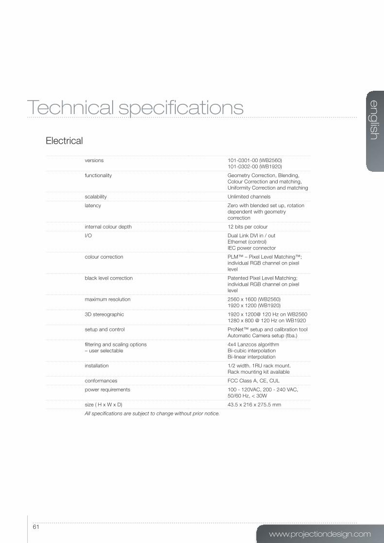
Technical specifi cations
Electrical
versions 101-0301-00 (WB2560)
101-0302-00 (WB1920)
functionality Geometry Correction, Blending,
Colour Correction and matching,
Uniformity Correction and matching
scalability Unlimited channels
latency Zero with blended set up, rotation
dependent with geometry
correction
internal colour depth 12 bits per colour
I/O Dual Link DVI in / out
Ethernet (control)
IEC power connector
colour correction PLM™ – Pixel Level Matching™;
individual RGB channel on pixel
level
black level correction Patented Pixel Level Matching;
individual RGB channel on pixel
level
maximum resolution 2560 x 1600 (WB2560)
1920 x 1200 (WB1920)
3D stereographic 1920 x 1200@ 120 Hz on WB2560
1280 x 800 @ 120 Hz on WB1920
setup and control ProNet™ setup and calibration tool
Automatic Camera setup (tba.)
fi ltering and scaling options
– user selectable
4x4 Lanzcos algorithm
Bi-cubic interpolation
Bi-linear interpolation
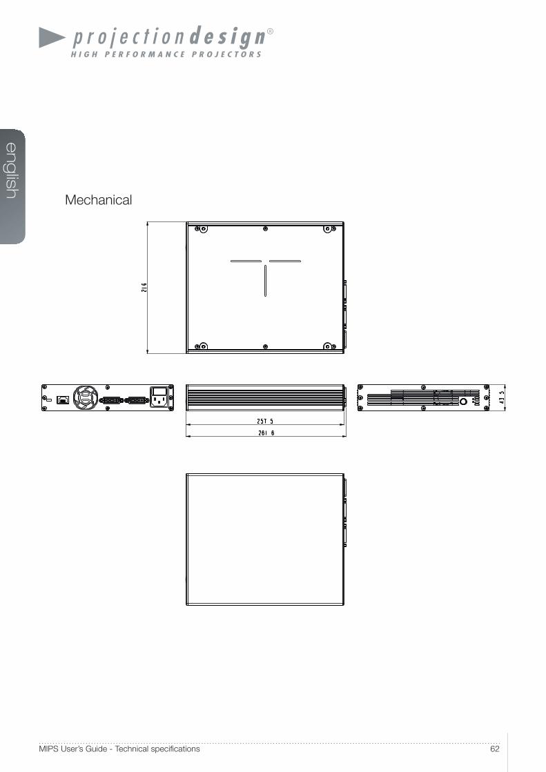
installation 1/2 width. 1RU rack mount.
Rack mounting kit available
conformances FCC Class A, CE, CUL
power requirements 100 - 120VAC, 200 - 240 VAC,
50/60 Hz, < 30W
size ( H x W x D) 43.5 x 216 x 275.5 mm
All specifications are subject to change without prior notice.
en
glis
h
62MIPS User’s Guide - Technical specifi cations
Mechanical
www.projectiondesign.com
en
glis
h
63
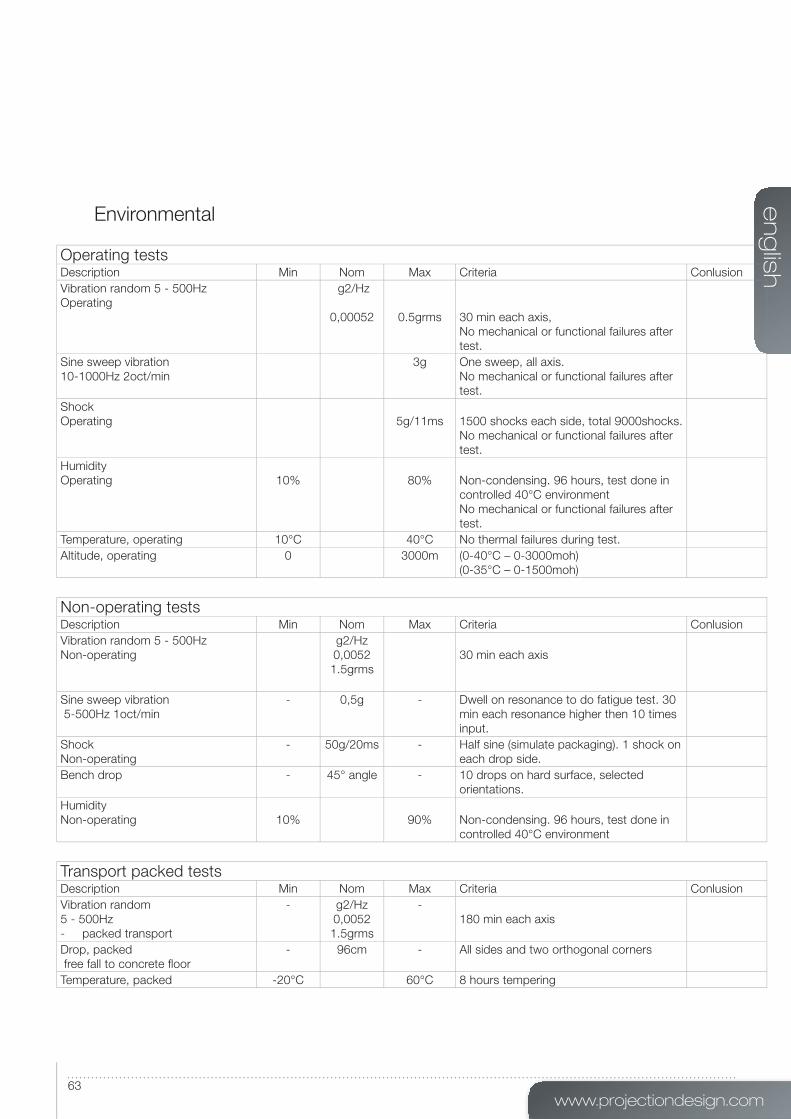
Environmental
Operating testsDescription Min Nom Max Criteria Conlusion
Vibration random 5 - 500Hz
Operating
g2/Hz
0,00052 0.5grms
30 min each axis,
No mechanical or functional failures after
test.
Sine sweep vibration
10-1000Hz 2oct/min
3g One sweep, all axis.
No mechanical or functional failures after
test.
Shock
Operating 5g/11ms 1500 shocks each side, total 9000shocks.
No mechanical or functional failures after
test.
Humidity
Operating 10% 80% Non-condensing. 96 hours, test done in
controlled 40°C environment
No mechanical or functional failures after
test.
Temperature, operating 10°C 40°C No thermal failures during test.
Altitude, operating 0 3000m (0-40°C – 0-3000moh)
(0-35°C – 0-1500moh)
Non-operating testsDescription Min Nom Max Criteria Conlusion
Vibration random 5 - 500Hz
Non-operating
g2/Hz
0,0052
1.5grms
30 min each axis
Sine sweep vibration
5-500Hz 1oct/min
- 0,5g - Dwell on resonance to do fatigue test. 30
min each resonance higher then 10 times
input.
Shock
Non-operating
- 50g/20ms - Half sine (simulate packaging). 1 shock on
each drop side.
Bench drop - 45° angle - 10 drops on hard surface, selected
orientations.
Humidity
Non-operating 10% 90% Non-condensing. 96 hours, test done in
controlled 40°C environment
Transport packed testsDescription Min Nom Max Criteria Conlusion
Vibration random
5 - 500Hz
- packed transport
- g2/Hz
0,0052
1.5grms
-
180 min each axis
Drop, packed
free fall to concrete fl oor
- 96cm - All sides and two orthogonal corners
Temperature, packed -20°C 60°C 8 hours tempering

en
glis
h
64MIPS User’s Guide - Technical specifi cations

www.projectiondesign.com
en
glis
h
65
Table of fi gures
Figure 5-1. MIPS system overview 15
Figure 5-2. Rack mount plate 16
Figure 5-3. Rack mounted 16
Figure 6-4. Overview of ProNet.site 18
Figure 6-5. MIPS Calibrator, Device View. 19
Figure 6-6. File menu, Device View. 20
Figure 6-7. The Device Tree in the Device Pool. 20
Figure 6-8. Toolbars, shown with and without help texts. 21
Figure 6-9. Clearing calibration 22
Figure 6-10. Application and Network settings. 22
Figure 6-11. MIPS software upgrade window. 23
Figure 6-12. EDID Administration. 24
Figure 6-13. Switching views from Calibrator view to Device view and back. 24
Figure 6-14. Calibration toolbar, without and with help texts. 25
Figure 6-15. MIPS Navigator 25
Figure 6-16. Top toolbar window navigation 26
Figure 6-17. Calibration Panel Toolbar, without and with help texts. 26
Figure 6-18. Set colors control box 27
Figure 7-19. Warping algorithm setup 30
Figure 7-20. Scaling filters 31
Figure 7-21. Working with the perspective transform 32
Figure 7-22. Working with the Mesh Smythe algorithm 33
Figure 7-23. Mesh Bezier with 1x1 grid 34
Figure 7-24. Working with Mesh Bezier, simple mapping 35
Figure 8-25. Basic edge blending. 38
Figure 8-26. Adding a blend zone. 39
Figure 8-27. Add blend zone window. 40
Figure 8-28. Working with advanced edge blending. 40
Figure 8-29. Adjusting the blend drop off curve. 41
Figure 9-30. Adding test patterns 43
Figure 9-31. Test Image Setup window 43
Figure 9-32. Circle test patterns 44
Figure 9-33. Grid (Pixel) test pattern 45
Figure 9-34. Grid (Angle) test pattern 46
Figure 9-35. Disabling the warp grid 46
Figure 10-36. Start BLM tool. 47
Figure 10-37. Adding Black Level Management lines. 48
Figure 10-38. Multiple Black Level Management lines added. 48
Figure 10-39. Connecting the first and last Black Level Management points. 49
Figure 10-40. Adjusting black level. 50
Figure 11-41. Starting the clip tool 51
Figure 11-42. Adding the first line in a clip area. 52
Figure 11-43. Adding multiple side in a clip area. 53
Figure 11-44. Clipping area complete. 54
Figure 12-45. Save current calibration to the MIPS unit 57
Figure 12-46. Backup up calibration data. 58
Figure 12-47. Selecting folder for backup 58

en
glis
h
66Name of Chapter
Figure 12-48. Restore calibration from control PC 59

authorised distribution in
United Kingdom and IrelandRegus House, Herons Way, Chester Business Park,Chester, CH4 9QR, United Kingdomph +44 (0)1244 893 231fx +47 69 30 45 [email protected]
Germany, Austria, SwitzerlandStuttgartph +49 7153 958263mo +49 (176) 2316 0345fx +47 69 30 45 [email protected]
Benelux regionPostbus 594190CB Geldermalsen, The Netherlandsph +31 (0) 345753314fx +31 (0) [email protected]
Southern Europe Via Plinio 43, I-20129 Milano (MI), Italyph +39 02 45471864fx +39 02 45471865 [email protected]
Spain and PortugalGorrondatxe15, bajo A48640 Berango, Spainph 34 676 266 301fx +47 69 30 45 [email protected]
head office
projectiondesign asHabornveien 53N-1630 Gamle Fredrikstad, Norwayph +47 69 30 45 50fx +47 69 30 45 [email protected]
the Americasprojectiondesign LLC 295 North Street,Teterboro, NJ 07608, USA ph +1 888 588 1024fx +1 201 288 [email protected]
South Africa, Africa, Middle East and Oceania1 Peterhof CloseHout Bay 7806, South Africaph + 27 21 79 00 018fx +47 69 30 45 [email protected][email protected]
Middle EastP.O. Box 17633Jebel Ali Free Zone L.O.B. 15, Office 212, Dubai, UAEph +97150 6579827fx +47 69 30 45 [email protected]
Asia161 Kallang Way, #04-05 Kolam Ayer Industrial Estate, Singapore 349247ph +65 9621 7421fx +47 69 30 45 80 [email protected]
India, including SAARCMumbaiph +91 982 061 0670fx +47 69 30 45 [email protected]
©2010 projectiondesign AS. All rights reserved. All brands and trade names are the property of their respective owners. Specifi cations subject to
change without prior notice. All values are typical and may vary. Please visit our website for latest specifi cations and product offerings.
601-0
206-0
0
pro
jec
tio
nd
es
ign
loc
ati
on
s
www.projectiondesign.com