Embed Size (px)
Citation preview
1477-9226(2008)40;1-1
Number 40 | 28 October 2008 | Pages 5389–5512
PERSPECTIVEYu et al.Functional carbonaceous materials from hydrothermal carbonization of biomass
PERSPECTIVEWhittinghamInorganic nanomaterials for batteries
ISSN 1477-9226
www.rsc.org/dalton
An international journal of inorganic chemistry

This paper is published as part of a Dalton Transactions theme issue on:
Nanomaterials for alternative energy sources
Guest editor: Andrew Barron Rice University, Houston, Texas, USA
Published in issue 40, 2008 of Dalton Transactions
Image reproduced by permission of Shu-Hong Yu Other papers published in this issue include: Nanostructured thin solid oxide fuel cells with high power density Alex Ignatiev, Xin Chen, Naijuan Wu, Zigui Lu and Laverne Smith, Dalton Trans., 2008, DOI: 10.1039/b805658g
Inorganic nanomaterials for batteries M. Stanley Whittingham, Dalton Trans., 2008, DOI: 10.1039/b806372a
Raman spectroscopy of charge transfer interactions between single wall carbon nanotubes and [FeFe] hydrogenase Jeffrey L. Blackburn, Drazenka Svedruzic, Timothy J. McDonald, Yong-Hyun Kim, Paul W. King and Michael J. Heben, Dalton Trans., 2008, DOI: 10.1039/b806379f
Shape control of inorganic materials via electrodeposition Kyoung-Shin Choi, Dalton Trans., 2008, DOI: 10.1039/b807848c
Visit the Dalton Transactions website for more cutting-edge inorganic materials research
www.rsc.org/dalton

PERSPECTIVE www.rsc.org/dalton | Dalton Transactions
Functional carbonaceous materials from hydrothermal carbonization ofbiomass: an effective chemical process
Bo Hu, Shu-Hong Yu,* Kan Wang, Lei Liu and Xue-Wei Xu
Received 18th March 2008, Accepted 18th April 2008First published as an Advance Article on the web 26th June 2008DOI: 10.1039/b804644c
Recently, much attention has been attracted to the use of biomass to produce functional carbonaceousmaterials from the viewpoint of economic, environmental and societal issues. Among differenttechniques, the hydrothermal carbonization (HTC) process, a traditional but recently revived method,presents superior characteristics that make it a promising route of wide potential application. Thisperspective gives an overview of the latest advances in the HTC process of functional carbonaceousmaterials from biomass. First, we discuss the preparation of carbonaceous materials synthesized by theuse of either highly directed or catalyst/template-assisted methods, from crude plant materials andcarbohydrates respectively. These carbonaceous materials not only have special morphologies, such asnanospheres, nanocables, nanofibers, submicrocables, submicrotubes and porous structures, but alsocontain rich functional groups which can greatly improve hydrophilicity and chemical reactivity.Further, a general look is cast on the applications of this kind of carbonaceous materials inenvironmental, catalytic and electrical areas. Recent advances have demonstrated that the HTC processfrom biomass can provide promising methods for the rational design of a rich family of carbonaceousand hybrid functional carbon materials with important applications.
1. Introduction
Since the discovery of fullerenes1 and carbon nanotubes,2 the syn-thesis of functional carbonaceous materials has been a hot topic,motivated by its potential importance in catalyst supports, carbonfixation, adsorbents, gas storage, electrode, carbon fuel cells anddrug delivery.3 Foremost among the research changes is the shiftingof the production of carbonaceous materials and energy from fossilfuels to biomass. Biomass, because of its low value, huge amount,rapid regeneration, easy access and environmental friendship, has
Division of Nanomaterials & Chemistry, Hefei National Laboratory forPhysical Sciences at Microscale, University of Science and Technology ofChina, Hefei, P. R. China. E-mail: [email protected]; Fax: +86 (0)5513603040
Bo Hu
Bo Hu received his BS degree in2002 and MS degree in 2005,both in chemical engineering andtechnology from Hefei Univer-sity of Technology, and finallyhis PhD in chemistry from theUniversity of Science and Tech-nology of China in 2008 super-vised by Prof. Shu-Hong Yu.He is interested in the synthesisof carbonaceous materials byhydrothermal carbonization pro-cesses from biomass, the car-bonization mechanism and theself-assembly of nanoparticles.
Shu-Hong Yu
Shu-Hong Yu received his PhDin 1998, joined the Tokyo Insti-tute of Technology in 1999 andthen the Max Planck Institute(2001–2). Appointed CheungKong Professor in 2006, he nowleads the Division of Nanomate-rials & Chemistry at USTC. Re-search interests include bio-inspired synthesis and the self-assembly of nanostructured ma-terials. He is a board memberof Current Nanoscience andChinese Journal of InorganicChemistry.
a qualification as a promising starting material for the synthesisof these functional carbonaceous materials in spite of the debatesamong many scientists and engineers upon biofuels,4 bioenergy5
and biomaterials.6
Yet, whether the biomass conversion system is thermochemicalor biological, there still doesn’t appear to be a satisfactory andoptimal process.7 Besides, the traditional synthesis of carbonmaterials via hydrothermal carbonization always relies on harshconditions,8 e.g. carbon nanofibers have been prepared undera high temperature (up to 800 ◦C) and high pressure (up to100 MPa).9 In contrast, solvothermal carbonization prevailingrecent years usually relies on organic and volatile solvents.10,11
As an alternative, the hydrothermal carbonization (HTC) processreviving recently, however, has great potential to function as
5414 | Dalton Trans., 2008, 5414–5423 This journal is © The Royal Society of Chemistry 2008
the most promising route for its intrinsic properties, such ashigh carbon efficiency3b under mild conditions (≤200 ◦C), andabundant functional groups remaining on the product surface.3b,12
In retrospect the HTC process, an environmentally friendlyroute that uses water as solvent and proceeds in a sealed reactioncontainer under a controlled temperature between 100 and200 ◦C, has evolved over a long history.13 In 1913, Bergius13a firstdescribed the hydrothermal transformation of cellulose into coal-like materials and early works mainly focus on the preparationof biofuels from biomass.13 More recently, the HTC process hasbeen used for the synthesis of uniform carbon spheres using sugaror glucose as precursors under mild conditions (≤ 200 ◦C) atthe beginning of the new century.14,15 Subsequently, a variety offunctional carbonaceous materials from biomass via the HTCprocess have been synthesized with promising prospects in variousapplications.3,16
In this perspective, we discuss the latest advance in the synthesisof functional carbonaceous materials from different biomassesvia the HTC process. This perspective is mainly composed of twoparts. In the first part, the synthesis of carbonaceous materialsfrom crude plant materials and carbohydrates is discussed, eitherdirected or catalyst/template-assisted. In the second part, byciting several detailed discussed cases, we have a rough look atthe environmental, catalytic and electrical applications of thecarbonaceous and hybrid materials produced under the HTCcondition. Finally, we will give the summary and outlook on thisactive research topic.
2. Hydrothermal synthesis of carbonaceous materials
The HTC process for the synthesis of functional carbonaceousmaterials from biomass has been intensively studied. Usually,biomass used for this process includes crude plant materials andcarbohydrates. Crude plant materials are directly obtained fromagricultural residues, wood and herbaceous energy crops, whilecarbohydrates normally include sugars, starch, hemicellulose,cellulose and other dehydration products of glucose, 2-furaldehyde(furfural) and hydroxymethylfurfural. In the following sections, wewill discuss the recent advances in the area of controlled growthand surface functionalization of various carbonaceous materialsby the use of crude plant materials or carbohydrates via the HTCprocess (Scheme 1).
2.1 Crude plant materials
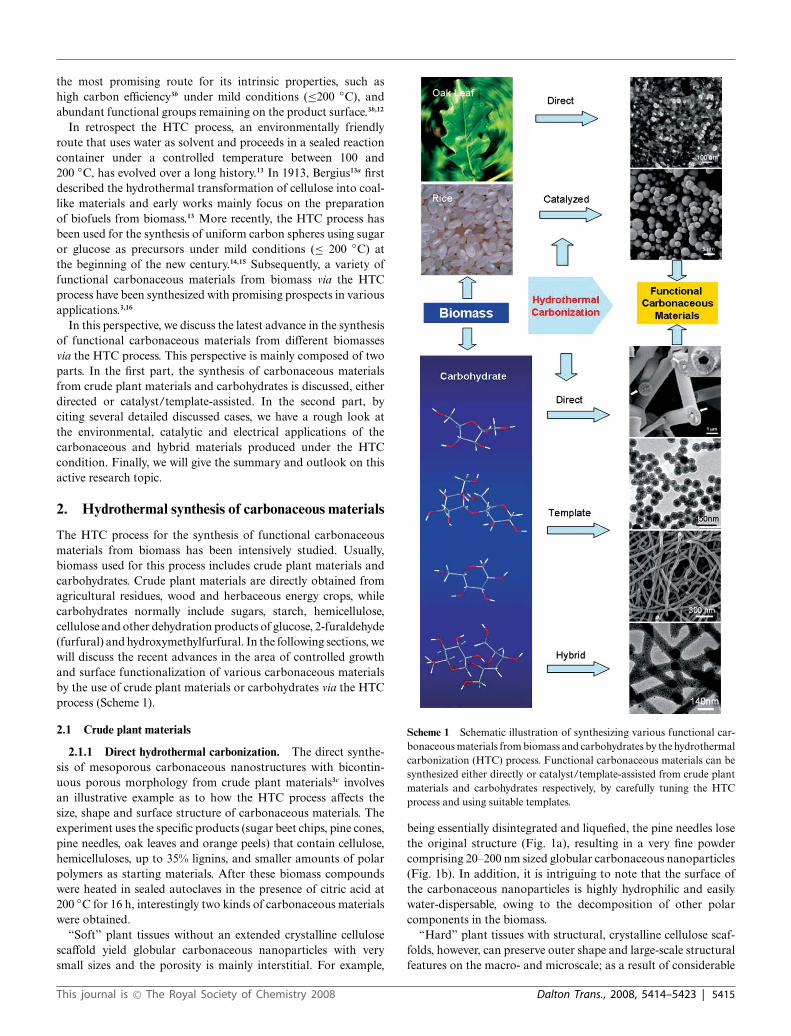
2.1.1 Direct hydrothermal carbonization. The direct synthe-sis of mesoporous carbonaceous nanostructures with bicontin-uous porous morphology from crude plant materials3c involvesan illustrative example as to how the HTC process affects thesize, shape and surface structure of carbonaceous materials. Theexperiment uses the specific products (sugar beet chips, pine cones,pine needles, oak leaves and orange peels) that contain cellulose,hemicelluloses, up to 35% lignins, and smaller amounts of polarpolymers as starting materials. After these biomass compoundswere heated in sealed autoclaves in the presence of citric acid at200 ◦C for 16 h, interestingly two kinds of carbonaceous materialswere obtained.
“Soft” plant tissues without an extended crystalline cellulosescaffold yield globular carbonaceous nanoparticles with verysmall sizes and the porosity is mainly interstitial. For example,
Scheme 1 Schematic illustration of synthesizing various functional car-bonaceous materials from biomass and carbohydrates by the hydrothermalcarbonization (HTC) process. Functional carbonaceous materials can besynthesized either directly or catalyst/template-assisted from crude plantmaterials and carbohydrates respectively, by carefully tuning the HTCprocess and using suitable templates.
being essentially disintegrated and liquefied, the pine needles losethe original structure (Fig. 1a), resulting in a very fine powdercomprising 20–200 nm sized globular carbonaceous nanoparticles(Fig. 1b). In addition, it is intriguing to note that the surface ofthe carbonaceous nanoparticles is highly hydrophilic and easilywater-dispersable, owing to the decomposition of other polarcomponents in the biomass.
“Hard” plant tissues with structural, crystalline cellulose scaf-folds, however, can preserve outer shape and large-scale structuralfeatures on the macro- and microscale; as a result of considerable
This journal is © The Royal Society of Chemistry 2008 Dalton Trans., 2008, 5414–5423 | 5415

Fig. 1 HRSEM of pine needles (a) before and (b) after being hydrother-mally carbonized at 200 ◦C for 12 h; (c) low-magnification SEM overviewof a HTC-treated oak leaf; (d) high-magnification picture of the sameHTC- treated oak leaf. Images (a)–(d) reprinted with permissionfrom M. M. Titirici, A. Thomas, S. H. Yu, J. O. Muller and M. Antonietti,Chem. Mater., 2007, 19, 4205–4212.3c C© 2007 American Chemical Society.
mass loss, there arises the significant structural change on thenanometer scale, resulting in a sponge-like, bicontinuous car-bonaceous network with a well-defined mesoporous structure. Asthe low-magnified SEM images show, the oak leaves preserve thecellular, layered architecture of the carbohydrate matrix (Fig. 1c).On the other hand, the high-magnified SEM images indicate thatthe scaffold is rearranged and “opened up” with a well-developedpore system comprising apparent pore sizes from 10 to 100 nm(Fig. 1d). The transmission electron microscopy (TEM) images ofa typical, delaminated thin part of the HTC-treated oak leaves(Fig. 2) nicely support the SEM observations of the surfacestructure of such materials. In addition, the surface of mesoporous
Fig. 2 TEM picture of the local structure HTC-treated oak leaves. Imagesreprinted with permission from M. M. Titirici, A. Thomas, S. H. Yu, J. O.Muller and M. Antonietti, Chem. Mater., 2007, 19, 4205–4212.3c C© 2007American Chemical Society.
carbonaceous materials proved water-wettable, due to the presenceof polar groups immobilized at the biocarbon/water interface.
2.1.2 Catalyzed hydrothermal carbonization. It is essential togain an understanding of the catalysis mechanism in the HTCprocess during the formation of carbonaceous materials and theassociated surface modification. Recently, Yu et. al. have reportedthat hydrothermal carbonization of starch can be effectivelyaccelerated by the presence of metal ions which also directs thesynthesis towards various metal–carbon nanoarchitectures, suchas Ag@carbon nanocables,3a and Ag@carbon-rich compositemicrocables.16c In addition, the presence of [Fe(NH4)2(SO4)2] caneffectively catalyze the carbonization of raw rice grains in theHTC process.12 The insoluble part of the grain forms larger,porous carbonized species, and preserves the primary grainmicrostructure, which is different along the body of the grain(Fig. 3a and c). Interestingly, the majority of the 5 nm products arecomposed of single carbon nanofibers, keeping the primary fibrousstructure of the rice tissue on the nanometer scale (Fig. 3b). Thesoluble fraction forms carbon microspheres (Fig. 3d).
Fig. 3 (a) Photograph of rice grains. (b)–(d) SEM images of thecarbonized product: rice grains (5 g), [Fe(NH4)2(SO4)2] (5 mmol), 200 ◦C,12 h, pH 4; (b) coexistence of carbon spheres and a carbonized,microstructured biological tissue; (c) organized carbon scaffold replicatinga different biological motif of the nonsoluble carbohydrates in rice;(d) pure carbon spheres collected from the solution generated from thesoluble polysaccharides. Images (a)–(d) reprinted with permission fromX. J. Cui, M. Antonietti and S. H. Yu, Small, 2006, 2, 756–759.12 C© 2006Wiley-VCH.
2.2 Carbohydrates
2.2.1 Carbonaceous materials. Traditionally, when sugar orglucose is used as a precursor, the HTC process tends to generatemonodispersed colloidal carbon microspheres.14,15 However, theproper template or additives can control the synthesis of newcarbonaceous materials with special and complex structures. Aparticularly nice case is the synthesis of uniform carbonaceousnanofibers by the HTC process, using glucose and Te nanowiresof several nanometers in diameter as starting materials.16a
5416 | Dalton Trans., 2008, 5414–5423 This journal is © The Royal Society of Chemistry 2008
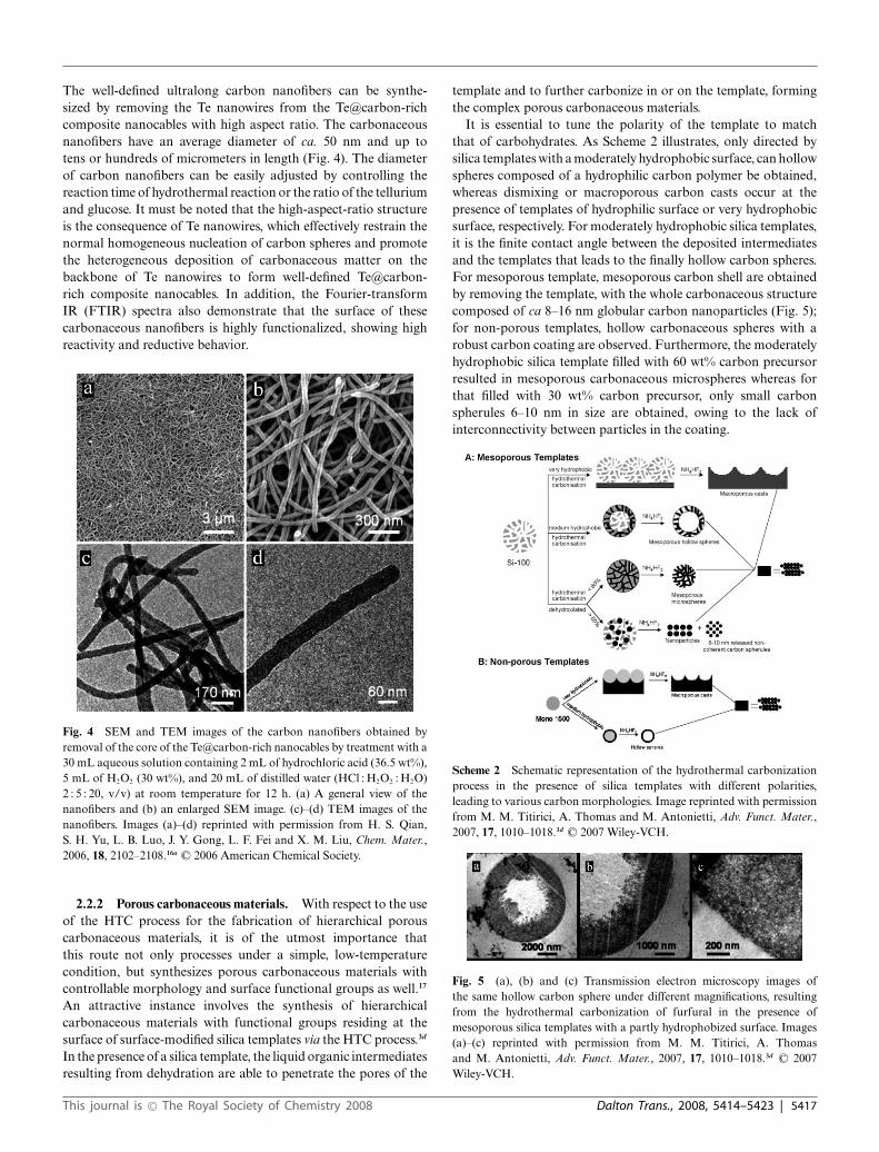
The well-defined ultralong carbon nanofibers can be synthe-sized by removing the Te nanowires from the Te@carbon-richcomposite nanocables with high aspect ratio. The carbonaceousnanofibers have an average diameter of ca. 50 nm and up totens or hundreds of micrometers in length (Fig. 4). The diameterof carbon nanofibers can be easily adjusted by controlling thereaction time of hydrothermal reaction or the ratio of the telluriumand glucose. It must be noted that the high-aspect-ratio structureis the consequence of Te nanowires, which effectively restrain thenormal homogeneous nucleation of carbon spheres and promotethe heterogeneous deposition of carbonaceous matter on thebackbone of Te nanowires to form well-defined Te@carbon-rich composite nanocables. In addition, the Fourier-transformIR (FTIR) spectra also demonstrate that the surface of thesecarbonaceous nanofibers is highly functionalized, showing highreactivity and reductive behavior.
Fig. 4 SEM and TEM images of the carbon nanofibers obtained byremoval of the core of the Te@carbon-rich nanocables by treatment with a30 mL aqueous solution containing 2 mL of hydrochloric acid (36.5 wt%),5 mL of H2O2 (30 wt%), and 20 mL of distilled water (HCl : H2O2 : H2O)2 : 5 : 20, v/v) at room temperature for 12 h. (a) A general view of thenanofibers and (b) an enlarged SEM image. (c)–(d) TEM images of thenanofibers. Images (a)–(d) reprinted with permission from H. S. Qian,S. H. Yu, L. B. Luo, J. Y. Gong, L. F. Fei and X. M. Liu, Chem. Mater.,2006, 18, 2102–2108.16a C© 2006 American Chemical Society.
2.2.2 Porous carbonaceous materials. With respect to the useof the HTC process for the fabrication of hierarchical porouscarbonaceous materials, it is of the utmost importance thatthis route not only processes under a simple, low-temperaturecondition, but synthesizes porous carbonaceous materials withcontrollable morphology and surface functional groups as well.17
An attractive instance involves the synthesis of hierarchicalcarbonaceous materials with functional groups residing at thesurface of surface-modified silica templates via the HTC process.3d
In the presence of a silica template, the liquid organic intermediatesresulting from dehydration are able to penetrate the pores of the
template and to further carbonize in or on the template, formingthe complex porous carbonaceous materials.
It is essential to tune the polarity of the template to matchthat of carbohydrates. As Scheme 2 illustrates, only directed bysilica templates with a moderately hydrophobic surface, can hollowspheres composed of a hydrophilic carbon polymer be obtained,whereas dismixing or macroporous carbon casts occur at thepresence of templates of hydrophilic surface or very hydrophobicsurface, respectively. For moderately hydrophobic silica templates,it is the finite contact angle between the deposited intermediatesand the templates that leads to the finally hollow carbon spheres.For mesoporous template, mesoporous carbon shell are obtainedby removing the template, with the whole carbonaceous structurecomposed of ca 8–16 nm globular carbon nanoparticles (Fig. 5);for non-porous templates, hollow carbonaceous spheres with arobust carbon coating are observed. Furthermore, the moderatelyhydrophobic silica template filled with 60 wt% carbon precursorresulted in mesoporous carbonaceous microspheres whereas forthat filled with 30 wt% carbon precursor, only small carbonspherules 6–10 nm in size are obtained, owing to the lack ofinterconnectivity between particles in the coating.
Scheme 2 Schematic representation of the hydrothermal carbonizationprocess in the presence of silica templates with different polarities,leading to various carbon morphologies. Image reprinted with permissionfrom M. M. Titirici, A. Thomas and M. Antonietti, Adv. Funct. Mater.,2007, 17, 1010–1018.3d C© 2007 Wiley-VCH.
Fig. 5 (a), (b) and (c) Transmission electron microscopy images ofthe same hollow carbon sphere under different magnifications, resultingfrom the hydrothermal carbonization of furfural in the presence ofmesoporous silica templates with a partly hydrophobized surface. Images(a)–(c) reprinted with permission from M. M. Titirici, A. Thomasand M. Antonietti, Adv. Funct. Mater., 2007, 17, 1010–1018.3d C© 2007Wiley-VCH.
This journal is © The Royal Society of Chemistry 2008 Dalton Trans., 2008, 5414–5423 | 5417
Besides, under the HTC process, the resulting carbonaceousmaterials remains rich in surface functional groups that areconfirmed by FTIR spectroscopy, X-ray photoelectron analysisand water porosimetry, since low temperatures guarantee thesurface of a considerable number of functional groups, such as–OH and –C=O groups bonded to the carbon framework. Thepresence of surface functional groups can greatly improve thehydrophilicity of carbonaceous materials and the stability of theirdispersions in aqueous systems.
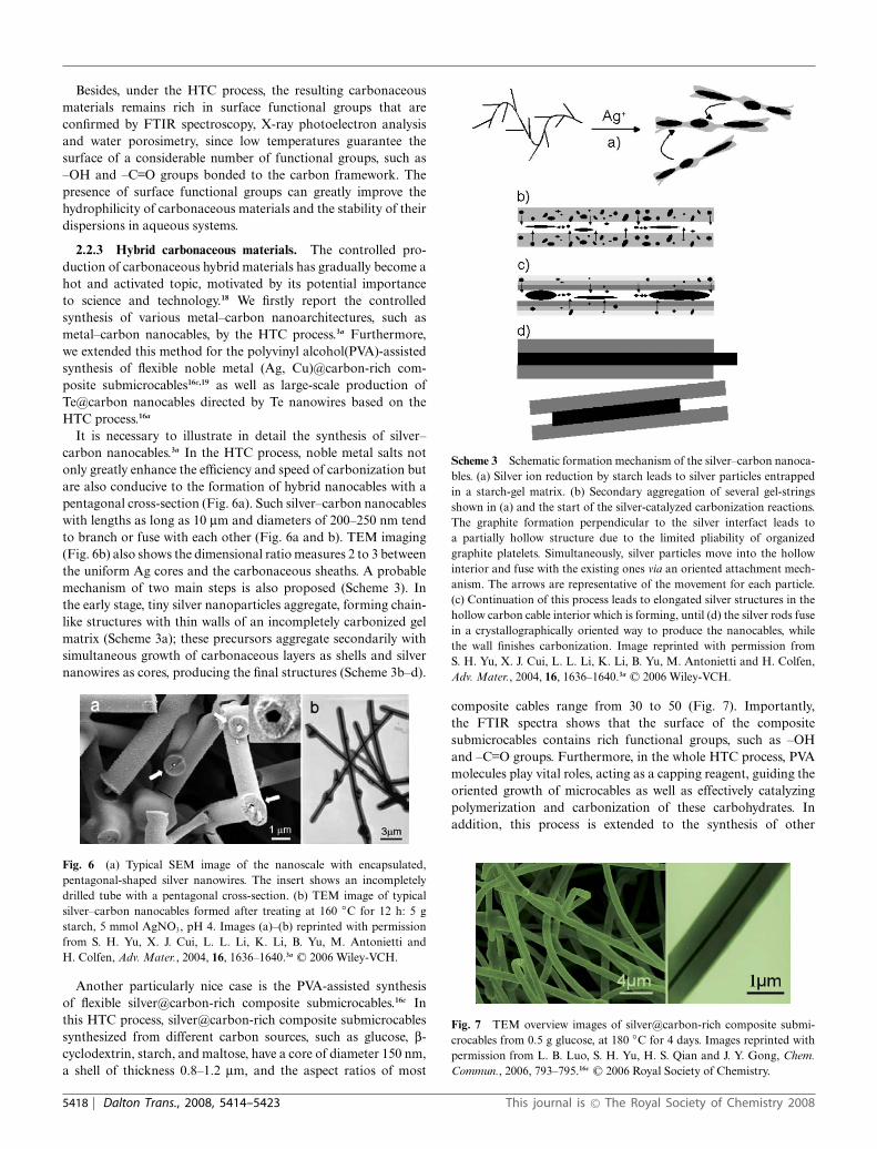
2.2.3 Hybrid carbonaceous materials. The controlled pro-duction of carbonaceous hybrid materials has gradually become ahot and activated topic, motivated by its potential importanceto science and technology.18 We firstly report the controlledsynthesis of various metal–carbon nanoarchitectures, such asmetal–carbon nanocables, by the HTC process.3a Furthermore,we extended this method for the polyvinyl alcohol(PVA)-assistedsynthesis of flexible noble metal (Ag, Cu)@carbon-rich com-posite submicrocables16c,19 as well as large-scale production ofTe@carbon nanocables directed by Te nanowires based on theHTC process.16a
It is necessary to illustrate in detail the synthesis of silver–carbon nanocables.3a In the HTC process, noble metal salts notonly greatly enhance the efficiency and speed of carbonization butare also conducive to the formation of hybrid nanocables with apentagonal cross-section (Fig. 6a). Such silver–carbon nanocableswith lengths as long as 10 mm and diameters of 200–250 nm tendto branch or fuse with each other (Fig. 6a and b). TEM imaging(Fig. 6b) also shows the dimensional ratio measures 2 to 3 betweenthe uniform Ag cores and the carbonaceous sheaths. A probablemechanism of two main steps is also proposed (Scheme 3). Inthe early stage, tiny silver nanoparticles aggregate, forming chain-like structures with thin walls of an incompletely carbonized gelmatrix (Scheme 3a); these precursors aggregate secondarily withsimultaneous growth of carbonaceous layers as shells and silvernanowires as cores, producing the final structures (Scheme 3b–d).
Fig. 6 (a) Typical SEM image of the nanoscale with encapsulated,pentagonal-shaped silver nanowires. The insert shows an incompletelydrilled tube with a pentagonal cross-section. (b) TEM image of typicalsilver–carbon nanocables formed after treating at 160 ◦C for 12 h: 5 gstarch, 5 mmol AgNO3, pH 4. Images (a)–(b) reprinted with permissionfrom S. H. Yu, X. J. Cui, L. L. Li, K. Li, B. Yu, M. Antonietti andH. Colfen, Adv. Mater., 2004, 16, 1636–1640.3a C© 2006 Wiley-VCH.
Another particularly nice case is the PVA-assisted synthesisof flexible silver@carbon-rich composite submicrocables.16c Inthis HTC process, silver@carbon-rich composite submicrocablessynthesized from different carbon sources, such as glucose, b-cyclodextrin, starch, and maltose, have a core of diameter 150 nm,a shell of thickness 0.8–1.2 mm, and the aspect ratios of most
Scheme 3 Schematic formation mechanism of the silver–carbon nanoca-bles. (a) Silver ion reduction by starch leads to silver particles entrappedin a starch-gel matrix. (b) Secondary aggregation of several gel-stringsshown in (a) and the start of the silver-catalyzed carbonization reactions.The graphite formation perpendicular to the silver interfact leads toa partially hollow structure due to the limited pliability of organizedgraphite platelets. Simultaneously, silver particles move into the hollowinterior and fuse with the existing ones via an oriented attachment mech-anism. The arrows are representative of the movement for each particle.(c) Continuation of this process leads to elongated silver structures in thehollow carbon cable interior which is forming, until (d) the silver rods fusein a crystallographically oriented way to produce the nanocables, whilethe wall finishes carbonization. Image reprinted with permission fromS. H. Yu, X. J. Cui, L. L. Li, K. Li, B. Yu, M. Antonietti and H. Colfen,Adv. Mater., 2004, 16, 1636–1640.3a C© 2006 Wiley-VCH.
composite cables range from 30 to 50 (Fig. 7). Importantly,the FTIR spectra shows that the surface of the compositesubmicrocables contains rich functional groups, such as –OHand –C=O groups. Furthermore, in the whole HTC process, PVAmolecules play vital roles, acting as a capping reagent, guiding theoriented growth of microcables as well as effectively catalyzingpolymerization and carbonization of these carbohydrates. Inaddition, this process is extended to the synthesis of other
Fig. 7 TEM overview images of silver@carbon-rich composite submi-crocables from 0.5 g glucose, at 180 ◦C for 4 days. Images reprinted withpermission from L. B. Luo, S. H. Yu, H. S. Qian and J. Y. Gong, Chem.Commun., 2006, 793–795.16c C© 2006 Royal Society of Chemistry.
5418 | Dalton Trans., 2008, 5414–5423 This journal is © The Royal Society of Chemistry 2008

carbonaceous materials, such as copper@carbon-rich compositesubmicrocables and carbonaceous submicrotubes.20
Meanwhile, the synthesis of SiO2@C microspheres is also veryattractive.21 In this HTC process, uniform and functionalizedSiO2@C microspheres can be synthesized with glucose as carbonprecursor and silica spheres as cores. A surprising feature of theproduct is that there exists a vacant region between the carbonshells and silica cores (Fig. 8). Such SiO2@C core-shell spherescan be further applied to prepare SiO2@C@SiO2, SiO2@SiO2 withvacant region between two SiO2 shells, noble metal nanoparticlesloaded on SiO2@C core–shell spheres, and hollow carbon capsulesthrough different synthetic processes. Furthermore, the surfaces ofSiO2@C microspheres are highly functionalized, display excellentchemical reactivity, and are able to reduce in situ noble-metal ionsto nanoparticles and load them onto the surface. These uniquecore–shell hybrid spherical composites could find applications ascatalyst supports, adsorbents, encapsulation, biomolecule reactorsand reaction templates.
Fig. 8 TEM images of representative SiO2@C core–shell micropheres.Images (a) and (b) reprinted with permission from Y. Wan, Y. L. Min andS. H. Yu, Langmuir, 2008, 24, 5024–5028.21 C© 2008 American ChemicalSociety.
From the discussion above, we can see that the HTC process is apromising method of the synthesis of various interesting carbona-ceous materials from biomass. Yet it must be noted that othermethods also perform well or even better in certain occasions,e.g. based on the combination of a solvothermal route and amild self-assembly approach, carbon-rich submicrotubes can besynthesized (Fig. 9).10,22 Amorphous carbonaceous nanoparticleswith functional groups are firstly produced by the carbonizationof glucose in pyridine solution, then these nanoparticles can self-assemble into submicrotubes by mixing the resulting solution withwater.
3. Applications of the carbonaceous materials
The existing and promising applications of carbonaceous andhybrid materials made from the HTC process include carbonfixation, chromatography, catalyst supports, gas-selective adsor-bents, drug delivery and electrode materials.23 The HTC processof biomass is currently the most efficient process, with “carbonefficiency” close to 1, to remove atmospheric CO2, which can bebound into carbonaceous materials. Based on the HTC process,rich functional groups remaining on the surface of variouscarbonaceous or hybrid materials can facilitate loading of noblemetal nanoparticles used as catalysts. Besides, the superior storage
Fig. 9 SEM and TEM images of the carbon-rich composite submicro-tubes. (a) A general overview of the submicrotubes. The insert photographimage is untreated solution (left) and after self-assembly the preparedsample redispersed in distilled water (right). (b) High-magnification SEMimages, clearly showing the open ends of these tubes. The insert TEM imageshows the tube structure. Images (a) and (b) reprinted with permission fromY. J. Zhan and S. H. Yu, J. Phys. Chem. C, 2008, 112, 4024–4028.10 C© 2008American Chemical Society.
performance of the carbonaceous hybrid materials made from theHTC process makes them suitable as anode material for lithium-ion batteries.
3.1 Environmental applications
Given climate changes and the role of CO2 therein, it would benecessary not only to slow down further CO2 emissions but alsoto develop a chemical “CO2 disposal” industry for sequesteringthe atmospheric CO2 from industrialization of past years. Thecoalification of biomass, the biggest carbon converter with thehighest efficiency to bind CO2 away from the atmosphere, by theHTC process, has a potential to function as the most efficient toolfor this target.3b First, the desirable acceleration of the coalificationof biomass by a factor of 106–109 makes it a technically attractive,realistic “artificial” instrument for fixing the carbon of biomasson large scales. Second, it is the most efficient strategy forcarbon fixation, with a “carbon efficiency” close to 1 (Fig. 10).3b
Also, compared to the traditional high-temperature carbonization
Fig. 10 Comparison of different energy and carbon exploitation schemesfrom carbohydrates, based on the stored combustion energy and the“carbon efficiency” of the transformation (CE). The “sum formula” of thecoalified plant material is a schematic simplification. The image is reprintedwith permission from M. M. Titirici, A. Thomas and M. Antonietti,New J. Chem., 2007, 31, 787–789.3b C© 2007 Royal Society of Chemistry.
This journal is © The Royal Society of Chemistry 2008 Dalton Trans., 2008, 5414–5423 | 5419
reactions, the HTC route processes under a mild conditionwith low-temperature (≤ 200 ◦C), and the high exothermiccharacteristic (i.e. liberating about a third of the combustionenergy of the sugars) further promotes the reaction with ease(Fig. 10). Therefore, the HTC process qualifies as an attractivetechnique to handle a significant part of the CO2 problem.
3.2 Catalytic applications
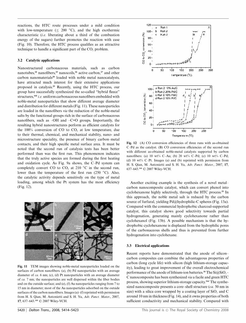
Nanostructured carbonaceous materials, such as carbonnanotubes,24 nanofibers,25 nanocoils,26 active carbon,27 and othercarbon nanomaterials28 loaded with noble metal nanocatalysts,have attracted much interest for their extensive applicationsproposed in catalysis.29 Recently, using the HTC process, ourgroup have successfully synthesized the so-called “hybrid fleece”structures,16b i.e. uniform carbonaceous nanofibers embedded withnoble-metal nanoparticles that show different average diameterand distribution for different metals (Fig. 11). These nanoparticlesare loaded in the nanofibers via the reduction of the noble-metalsalts by the functional groups rich in the surface of carbonaceousnanofibers, such as –OH and –C=O groups. Importantly, theresulting hybrid nanostructures perform as efficient catalysts forthe 100% conversion of CO to CO2 at low temperature, dueto their thermal, chemical, and mechanical stability, nano- andmicrostructure speciality, the presence of binary carbon–metalcontacts, and their high specific metal surface area. It must benoted that the second run of catalysis tests has been betterperformed than was the first run. This phenomenon indicatesthat the truly active species are formed during the first heatingand oxidation cycle. As Fig. 9a shows, the C–Pd system cancompletely convert CO to CO2 at 210 ◦C in the second run,lower than the temperature of the first run (250 ◦C). Also,the catalytic activity depends sensitively on the type of metalloading, among which the Pt system has the most efficiency(Fig. 12).
Fig. 11 TEM images showing noble-metal nanoparticles loaded on thesurfaces of carbon nanofibers. (a), (b) Pd nanoparticles with an averagediameter of ca. 6 nm; (c), (d) Pt nanoparticles with an average diameterof ca. 7 nm; the nanoparticles are well dispersed within the fiber bodiesand on the outside surface; and (e), (f) Au nanoparticles ranging from 7 to15 nm in diameter; most of the Au nanoparticles adsorbed on the outsidesurfaces of the carbon nanofibers. Images (a)–(f) reprinted with permissionfrom H. S. Qian, M. Antonietti and S. H. Yu, Adv. Funct. Mater., 2007,17, 637–643.16b C© 2007 Wiley-VCH.
Fig. 12 (A) CO conversion efficiencies of three runs with as-obtainedC–Pd as the catalyst. (B) CO conversion efficiencies of the second runwith different as-obtained noble-metal catalysts supported by carbonnanofibers: (a) 10 wt% C–Au; (b) 20 wt% C–Pd; (c) 10 wt% C–Pd;(d) 10 wt% C–Pt. Images (a) and (b) reprinted with permission fromH. S. Qian, M. Antonietti and S. H. Yu, Adv. Funct. Mater., 2007, 17,637–643.16b C© 2007 Wiley-VCH.
Another exciting example is the synthesis of a novel metal–carbon nanocomposite catalyst, which can convert phenol intocyclohexanone highly selectively, through the HTC process.29 Inthis approach, the noble metal salt is reduced by the carbonsource of furfural, yielding Pd@hydrophilic-C spheres (Fig. 13a).Compared with the commercial hydrophobic charcoal-supportedcatalyst, this catalyst shows good selectivity towards partialhydrogenation, generating mainly cyclohexanone rather thancyclohexanol (Fig. 13b). A possible mechanism is that the hy-drophobic cyclohexanone is displaced from the hydrophilic poresof the carbonaceous shells and thus is prevented from furtherhydrogenation into cyclohexane.
3.3 Electrical applications
Recent reports have demonstrated that the anode of silicon–carbon composites can combine the advantageous properties ofcarbon (long cycle life) with silicon (high lithium-storage capac-ity), leading to great improvement of the overall electrochemicalperformance of the anode of lithium-ion batteries.30 The Si@SiOx–C nanocomposite has been synthesized via a facile and green HTCprocess, showing superior lithium-storage capacity.16d The synthe-sized nanocomposite presents a core–shell structure (ca. 50 nm insize) with a silica core wrapped by a coating layer of SiOx and Caround 10 nm in thickness (Fig. 14), and it owns properties of bothsufficient conductivity and mechanical stability. Compared with
5420 | Dalton Trans., 2008, 5414–5423 This journal is © The Royal Society of Chemistry 2008
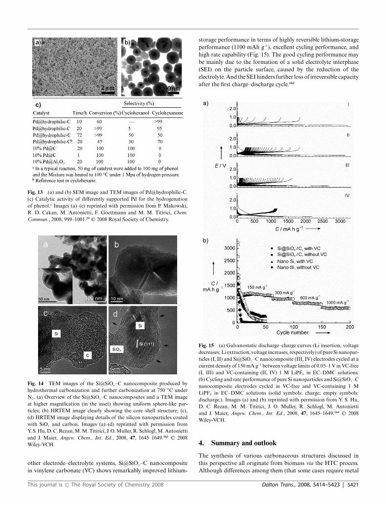
Fig. 13 (a) and (b) SEM image and TEM images of Pd@hydrophilic-C.(c) Catalytic activity of differently supported Pd for the hydrogenationof phenol.a Images (a)–(c) reprinted with permission from P. Makowski,R. D. Cakan, M. Antonietti, F. Goettmann and M. M. Titirici, Chem.Commun., 2008, 999–1001.29 C© 2008 Royal Society of Chemistry.
Fig. 14 TEM images of the Si@SiOx–C nanocomposite produced byhydrothermal carbonization and further carbonization at 750 ◦C underN2. (a) Overview of the Si@SiOx–C nanocomposites and a TEM imageat higher magnification (in the inset) showing uniform sphere-like par-ticles; (b) HRTEM image clearly showing the core–shell structure; (c),(d) HRTEM image displaying details of the silicon nanoparticles coatedwith SiOx and carbon. Images (a)–(d) reprinted with permission fromY. S. Hu, D. C. Rezan, M. M. Titirici, J. O. Muller, R. Schlogl, M. Antoniettiand J. Maier, Angew. Chem., Int. Ed., 2008, 47, 1645–1649.16d C© 2008Wiley-VCH.
other electrode–electrolyte systems, Si@SiOx–C nanocompositein vinylene carbonate (VC) shows remarkably improved lithium-
storage performance in terms of highly reversible lithium-storageperformance (1100 mAh g-1), excellent cycling performance, andhigh rate capability (Fig. 15). The good cycling performance maybe mainly due to the formation of a solid electrolyte interphase(SEI) on the particle surface, caused by the reduction of theelectrolyte. And the SEI hinders further loss of irreversible capacityafter the first charge–discharge cycle.16d
Fig. 15 (a) Galvanostatic discharge–charge curves (Li insertion, voltagedecreases; Li extraction, voltage increases, respectively) of pure Si nanopar-ticles (I, II) and Si@SiOx–C nanocomposite (III, IV) electrodes cycled at acurrent density of 150 mA g-1 between voltage limits of 0.05–1 V in VC-free(I, III) and VC-containing (II, IV) 1 M LiPF6 in EC–DMC solutions.(b) Cycling and rate performance of pure Si nanoparticles and Si@SiOx–Cnanocomposite electrodes cycled in VC-free and VC-containing 1 MLiPF6 in EC–DMC solutions (solid symbols: charge; empty symbols:discharge.). Images (a) and (b) reprinted with permission from Y. S. Hu,D. C. Rezan, M. M. Titirici, J. O. Muller, R. Schlogl, M. Antoniettiand J. Maier, Angew. Chem., Int. Ed., 2008, 47, 1645–1649.16d C© 2008Wiley-VCH.
4. Summary and outlook
The synthesis of various carbonaceous structures discussed inthis perspective all originate from biomass via the HTC process.Although differences among them (that some cases require metal
This journal is © The Royal Society of Chemistry 2008 Dalton Trans., 2008, 5414–5423 | 5421

ions as catalyst while some others rely on template to formspecific shapes) couldn’t be ignored, there do exist significantcommon features: high efficiency for the synthesis of carbonaceousmaterials, active surface rich in functional groups, and “green”sources from biomass, etc.
Importantly, the resulting structures are not only of aestheticand/or theoretical value, but of practical application poten-tial as well. The synthesized carbonaceous materials find theirplace in a variety of application areas: solving the environ-mental problem of CO2, catalyzing conversion from CO toCO2, improving the organic reaction efficiency and selectivity,and improving the electrochemical performance of an anode,owing to their distinctive characteristic from the HTC process ofbiomass.
Although the HTC process has been a prominent success in thesynthesis of many carbonaceous materials of distinctive structuresand rich functional groups, there still remains a blank as tothe components of the final products and the mechanism ofdetailed process. Yet human beings have never been satisfied onthe arduous journey for the pursuing of truth of “why this isthe case”. Further exploration in these areas will facilitate therational design of a variety of functional carbonaceous materialswith an ideal hierarchy when we gradually uncover the myste-rious veil of the mechanism behind hydrothermal carbonizationreaction.
Acknowledgements
S.-H. Yu acknowledges the funding support from the NationalScience Foundation of China (NSFC) (Grant Nos. 50732006,20325104, 20621061, 20671085), the Partner-Group of the ChineseAcademy of Sciences—the Max Planck Society, the 973 project(2005CB623601), Anhui Development Fund for Talent Personneland Anhui Education Committee (2006Z027, ZD2007004-1),the Scientific Research Foundation for the Returned OverseasChinese Scholars, and the Specialized Research Fund for theDoctoral Program (SRFDP) of Higher Education State EducationMinistry.
References
1 H. W. Kroto, J. R. Heath, S. C. Brien, R. F. Curl and R. E. Smalley,Nature, 1985, 318, 162–163.
2 S. Iijima, Nature, 1991, 354, 56–58.3 (a) S. H. Yu, X. J. Cui, L. L. Li, K. Li, B. Yu, M. Antonietti and H.
Colfen, Adv. Mater., 2004, 16, 1636–1640; (b) M. M. Titirici, A. Thomasand M. Antonietti, New J. Chem., 2007, 31, 787–789; (c) M. M. Titirici,A. Thomas, S. H. Yu, J. O. Muller and M. Antonietti, Chem. Mater.,2007, 19, 4205–4212; (d) M. M. Titirici, A. Thomas and M. Antonietti,Adv. Funct. Mater., 2007, 17, 1010–1018.
4 (a) K. Sanderson, Nature, 2006, 444, 673–676; (b) T. H. Deluca, Science,2006, 312, 1743–1744; (c) M. Downing, Science, 2006, 312, 1745–1746; (d) D. Connor and I. Minguez, Science, 2006, 312, 1743–1743;(e) T. Dalgaard, U. Jorgensen, J. E. Olesen, E. S. Jensen and E. S.Kristensen, Science, 2006, 312, 1743–1743; (f) S. E. Koonin, Science,2006, 312, 1744–1744; (g) M. W. Palmer, Science, 2006, 312, 1745–1745.
5 (a) K. R. Brower, Science, 2006, 312, 1744–1744; (b) C. J. Cleveland,C. A. S. Hall and R. A. Herendeen, Science, 2006, 312, 1746–1746;(c) B. H. Davison, A. J. Ragauskas, R. Templer, T. J. Tschaplinski andJ. R. Mielenz, Science, 2006, 312, 1744–1745; (d) E. Farrell, R. J. Plevin,B. T. Turner, A. D. Jones, M. O’Hare and D. M. Kammen, Science,2006, 312, 1747–1748; (e) A. E. Farrell, R. J. Plevin, B. T. Turner, A. D.
Jones, M. O’Hare and D. M. Kammen, Science, 2006, 311, 506–508;(f) A. E. Farrell, Science, 2006, 312, 1748–1748; (g) R. K. Kaufmann,Science, 2006, 312, 1747–1747.
6 (a) J. Lehmann, Nature, 2007, 447, 143–144; (b) D. R. Dodds andR. A. Gross, Science, 2007, 318, 1250–1251; (c) A. J. Ragauskas, C. K.Williams, B. H. Davison, G. Britovsek, J. Cairney, C. A. Eckert, W. J.Frederick, J. P. Hallett, D. J. Leak, C. L. Liotta, J. R. Mielenz, R.Murphy, R. Templer and T. Tschaplinski, Science, 2006, 311, 484–489.
7 (a) L. D. Schmidt and P. J. Dauenhauer, Nature, 2007, 447, 914–915;(b) L. Lynd, N. Greene, B. Dale, M. Laser, D. Lashof, M. Wang and C.Wyman, Science, 2006, 312, 1746–1747; (c) T. W. Patzek, Science, 2006,312, 1747–1747; (d) D. Tilman, J. Hill and C. Lehman, Science, 2006,314, 1598–1600; (e) N. Hagens, R. Costanza and K. Mulder, Science,2006, 312, 1746–1746.
8 (a) A. Thess, R. Lee, P. Nikolaev, H. J. Dai, P. Petit, J. Robert, C. H.Xu, Y. H. Lee, S. G. Kim, A. G. Rinzler, D. T. Colbert, G. E. Scuseria,D. Tomanek, J. E. Fischer and R. E. Smalley, Science, 1996, 273,483–487; (b) M. Joseyacaman, M. Mikiyoshida, L. Rendon and J. G.Santiesteban, Appl. Phys. Lett., 1993, 62, 657–659; (c) M. Joseyacaman,H. Terrones, L. Rendon and J. M. Dominguez, Carbon, 1995, 33, 669–678; (d) L. Gherghel, C. Kubel, G. Lieser, H. J. Rader and K. Mullen,J. Am. Chem. Soc., 2002, 124, 13130–13138; (e) Y. D. Li, Y. T. Qian,H. W. Liao, Y. Ding, L. Yang, C. Y. Xu, F. Q. Li and G. Zhou, Science,1998, 281, 246–247.
9 (a) Y. Gogotsi, J. A. Libera and M. Yoshimura, J. Mater. Res., 2000, 15,2591–2594; (b) J. Libera and Y. Gogotsi, Carbon, 2001, 39, 1307–1318;(c) Y. Gogotsi, J. A. Libera, A. Guvenc-Yazicioglu and C. M. Megaridis,Appl. Phys. Lett., 2001, 79, 1021–1023; (d) Y. Gogotsi, N. Naguib andJ. A. Libera, Chem. Phys. Lett., 2002, 365, 354–360; (e) Y. G. Gogotsiand M. Yoshimura, Nature, 1994, 367, 628–630.
10 Y. J. Zhan and S. H. Yu, J. Phys. Chem. C, 2008, 112, 4024–4028.11 G. Demazeau, J. Mater. Chem., 1999, 9, 15–18.12 X. J. Cui, M. Antonietti and S. H. Yu, Small, 2006, 2, 756–759.13 (a) F. Bergius, Die Anwendung hoher Drucke Bei chemischen Vorgangen
und eine Nachbidung des Entstehungsprozesses der Steinkohle, VerlagWilhelm Knapp, Halle an der Saale, Germany, 1913; (b) E. Berl andA. Schmidt, Justus Liebigs Ann. Chem., 1932, 493, 97–123; (c) E. Berl,A. Schmidt and H. Koch, Angew. Chem., 1932, 45, 0517–0519; (d) J. P.Schuhmacher, F. J. Huntjens and D. W. Vankrevelen, Fuel, 1960, 39,223–234.
14 Q. Wang, H. Li, L. Q. Chen and X. J. Huang, Carbon, 2001, 39, 2211–2214.
15 X. M. Sun and Y. D. Li, Angew. Chem., Int. Ed., 2004, 43, 597–601.
16 (a) H. S. Qian, S. H. Yu, L. B. Luo, J. Y. Gong, L. F. Fei and X. M.Liu, Chem. Mater., 2006, 18, 2102–2108; (b) H. S. Qian, M. Antoniettiand S. H. Yu, Adv. Funct. Mater., 2007, 17, 637–643; (c) L. B. Luo,S. H. Yu, H. S. Qian and J. Y. Gong, Chem. Commun., 2006, 793–795;(d) Y. S. Hu, D. C. Rezan, M. M. Titirici, J. O. Muller, R. Schlogl,M. Antonietti and J. Maier, Angew. Chem., Int. Ed., 2008, 47, 1645–1649.
17 (a) T. W. Kim and L. A. Solovyov, J. Mater. Chem., 2006, 16, 1445–1455; (b) Y. C. Liang, M. Hanzlik and R. Anwander, J. Mater. Chem.,2006, 16, 1238–1253; (c) M. M. Titirici, A. Thomas and M. Antonietti,J. Mater. Chem., 2007, 17, 3412–3418; (d) J. Wang, J. C. Groen, W.Yue, W. Zhou and M. O. Coppens, J. Mater. Chem., 2008, 18, 468–474.
18 (a) J. C. Yu, X. L. Hu, Q. Li and L. Z. Zhang, Chem. Commun., 2005,2704–2706; (b) B. Deng, A. W. Xu, G. Y. Chen, R. Q. Song and L. P.Chen, J. Phys. Chem. B, 2006, 110, 11711–11716; (c) X. M. Sun andY. D. Li, Langmuir, 2005, 21, 6019–6024.
19 J. Y. Gong, L. B. Luo, S. H. Yu, H. S. Qian and L. F. Fei, J. Mater.Chem., 2006, 16, 101–105.
20 J. Y. Gong, S. H. Yu, H. S. Qian, L. B. Luo and T. W. Li, J. Phys. Chem.C., 2006, 16, 101–105.
21 Y. Wan, Y. L. Min and S. H. Yu, Langmuir, 2008, 24, 5024–5028.22 S. S. Feng, M. L. Zhu, L. P. Lu and M. L. Guo, Chem. Commun., 2007,
4785–4787.23 H. Orikasa, J. Karoji, K. Matsui and T. Kyotani, Dalton Trans., 2007,
3757–3762.24 W. Z. Li, C. H. Liang, J. S. Qiu, W. J. Zhou, H. M. Han, Z. B. Wei,
G. Q. Sun and Q. Xin, Carbon, 2002, 40, 791–794.25 D. A. Bulushev, I. Yuranov, E. I. Suvorova, P. A. Buffat and L. Kiwi-
Minsker, J. Catal., 2004, 224, 8–17.
5422 | Dalton Trans., 2008, 5414–5423 This journal is © The Royal Society of Chemistry 2008

26 T. Hyeon, S. Han, Y. E. Sung, K. W. Park and Y. W. Kim, Angew.Chem., Int. Ed., 2003, 42, 4352–4356.
27 J. Prabhuram, X. Wang, C. L. Hui and I. M. Hsing, J. Phys. Chem. B,2003, 107, 11057–11064.
28 S. H. Joo, S. J. Choi, I. Oh, J. Kwak, Z. Liu, O. Terasaki and R. Ryoo,Nature, 2001, 412, 169–172.
29 P. Makowski, R. D. Cakan, M. Antonietti, F. Goettmann and M. M.Titirici, Chem. Commun., 2008, 999–1001.
30 (a) X. D. Wu, Z. X. Wang, L. Q. Chen and X. J. Huang, Elec-trochem. Commun., 2003, 5, 935–939; (b) J. Yang, B. F. Wang,K. Wang, Y. Liu, J. Y. Xie and Z. S. Wen, Electrochem. Solid-State Lett., 2003, 6, A154–A156; (c) S. H. Ng, J. Z. Wang, D.Wexler, K. Konstantinov, Z. P. Guo and H. K. Liu, Angew. Chem.,Int. Ed., 2006, 45, 6896–6899; (d) M. Holzapfel, H. Buqa, W.Scheifele, P. Novak and F. M. Petrat, Chem. Commun., 2005, 1566–1568.
This journal is © The Royal Society of Chemistry 2008 Dalton Trans., 2008, 5414–5423 | 5423