Embed Size (px)
Citation preview

CARDIFF SCHOOL OF ENGINEERING, CARDIFF UNIVERSITY, CF24 3AA, WALES, UK
An Intelligent System for Facility Management
Michael James Dibley
A thesis in support of the application for the award of a PhD degree from Cardiff University, Wales, UK.
October 2011


iii
Summary
A software system has been developed that monitors and interprets temporally changing
(internal) building environments and generates related knowledge that can assist in facility
management (FM) decision making. The use of the multi agent paradigm renders a system that
delivers demonstrable rationality and is robust within the dynamic environment that it
operates. Agent behaviour directed at working toward goals is rendered intelligent with
semantic web technologies. The capture of semantics though formal expression to model the
environment, adds a richness that the agents exploit to intelligently determine behaviours to
satisfy goals that are flexible and adaptable. The agent goals are to generate knowledge about
building space usage as well as environmental conditions by elaborating and combining near
real time sensor data and information from conventional building models. Additionally further
inferences are facilitated including those about wasted resources such as unnecessary lighting
and heating for example. In contrast, current FM tools, lacking automatic synchronisation with
the domain and rich semantic modelling, are limited to the simpler querying of manually
maintained models

iv

v
Declaration and Statements
This work has not previously been accepted in substance for any degree and is not
concurrently submitted in candidature for any degree.
Signed (candidate) Date
This thesis is being submitted in partial fulfilment of the requirements for the degree of PhD.
Signed (candidate) Date
This thesis is the result of my own independent work / investigation, except where otherwise
stated. Other sources are acknowledged by explicit references.
Signed (candidate) Date
I hereby give consent for my thesis, if accepted, to be available for photocopying and for inter-
library loan, and for the title and summary to be made available to outside organisations.
Signed (candidate) Date


vii
Other Works
The author has published / submitted the following related works:
Published
[1] M.J. Dibley, H. Li, J.C. Miles, and Y. Rezgui, "Towards Intelligent Agent Based Software for
Building Related Decision Support," Advanced Engineering Informatics, vol. 25, no. 2, pp.
311–329, Dec. 2011.
[2] M. J. Dibley, H. Li, J. C. Miles, and Y Rezgui, "A Semantic Model Provision for the Digital
Building," in Computing in Engineering EG-ICE Conference 2009, vol. 1, Berlin, 2009, pp. 83-
90.
[3] M. J. Dibley, H. Li, J. C. Miles, and Y. Rezgui, "Towards a Synchronized Semantic Model to
Support Aspects of Building Management," in Proceedings of the 7th IEEE International
Conference on Industrial Informatics, Cardiff, U.K., 2009, pp. 307-312.
[4] M. J. Dibley, H. Li, J. C. Miles, and Y. Rezgui, "The Application of Intelligent Agency in a
Software Model for Buildings," in Proceedings of the International Conference of Computing
in Civil and Building Engineering, Nottingham, UK, 2010, pp. 205-212.
Pending Publication
[5] M.J. Dibley, H. Li, J.C. Miles, and Y. Rezgui, "Cost Effective Intelligent Sensor System Design for
Real Time Building Monitoring," International Journal of Innovative Computing Information
and Control, submitted for publication.
[6] M.J. Dibley, H. Li, J.C. Miles, and Y. Rezgui, "Ontology Development Supporting Intelligent
Sensor Systems for Building Monitoring," Automation in Construction, submitted for
publication.
[7] M.J. Dibley, H. Li, J.C. Miles, and Y. Rezgui, "Ontology Evaluation and System Testing for Smart
Building Monitoring," Advanced Engineering Informatics, to be submitted.
[8] H. Li, M.J. Dibley, J.C. Miles, and Y. Rezgui, "A Systematic BIM Software Implementation
Framework applied in Building Facility Management," Advanced Engineering Informatics,
submitted for publication.
[9] H. Li, P. de Wilde, Y. Rafiq, and M.J. Dibley, "Improving Building Performance Simulation using
High Power Computing," Advanced Engineering Informatics, to be submitted.


ix
Contents
Summary ....................................................................................................................................... iii
Declaration and Statements .......................................................................................................... v
Other Works ................................................................................................................................. vii
Contents ........................................................................................................................................ ix
Table of Figures .......................................................................................................................... xvii
Table of Tables ............................................................................................................................ xix
1 Introduction .......................................................................................................................... 1
1.1 Aims and Objectives of the Research ........................................................................... 3
1.1.1 Hypotheses, Aims and Objectives ......................................................................... 3
1.2 Dependant Disciplines .................................................................................................. 5
1.3 High Level System Overview ......................................................................................... 5
1.4 Thesis Structure ............................................................................................................ 8
2 Knowledge Engineering and its Application in the Construction Sector ............................ 11
2.1 Informal Knowledge Representations ........................................................................ 12
2.1.1 Product Modelling in the Construction Sector ................................................... 13
2.1.2 Industry Foundation Classes ............................................................................... 15
2.1.3 Application of the Industry Foundation Classes ................................................. 17
2.2 Formal Knowledge Representations ........................................................................... 19
2.2.1 Description Logics ............................................................................................... 19
2.2.1.1 Combining Description Logics with Rule Support ........................................... 21
2.2.2 Ontology .............................................................................................................. 22
2.2.3 Web Ontology Language ..................................................................................... 23
2.2.3.1 Mapping from UML ......................................................................................... 24
2.2.3.2 Other Mappings and Translation .................................................................... 25
2.2.3.3 The Semantic Web .......................................................................................... 25
2.2.3.4 Ontology Interaction ....................................................................................... 26
2.2.4 Inference and Reasoner Support for OWL .......................................................... 26

x
2.2.4.1 General Features ............................................................................................. 27
2.2.4.2 A Common Application Programming Interface ............................................. 27
2.2.4.3 The Pellet Reasoner ......................................................................................... 28
2.2.4.4 The RACER Reasoner ....................................................................................... 29
2.2.4.5 Other Reasoners .............................................................................................. 29
2.2.5 OWL Tools ............................................................................................................ 29
2.2.6 Ontology Engineering .......................................................................................... 30
2.2.6.1 Ontology Development Methodologies Overview .......................................... 31
2.2.7 Ontological Resources for the IFMS Domain ....................................................... 33
2.2.8 Application of Shared Ontologies and Semantics ............................................... 35
2.3 Summary ...................................................................................................................... 39
3 The Multi Agent System Paradigm and its Application in the Construction Sector ............ 41
3.1 Multi Agent Systems .................................................................................................... 41
3.1.1 Multi Agents Systems and Rational Agency ........................................................ 41
3.1.2 The Belief Desire Intention Model....................................................................... 43
3.1.3 Logical Formulation ............................................................................................. 46
3.1.4 Implementable Systems ...................................................................................... 49
3.2 Agent Messaging ......................................................................................................... 51
3.2.1 Message Content ................................................................................................. 53
3.2.1.1 SL as Message Content .................................................................................... 53
3.2.1.2 OWL as Message Content ................................................................................ 55
3.3 Agent Development Methodologies ........................................................................... 56
3.4 Applications of the Multi Agent Paradigm in the Construction Sector ....................... 59
3.4.1 Intelligent Buildings and Agency ......................................................................... 60
3.5 Alternatives to Deliver Aspects of Agency ................................................................... 62
3.6 Summary ...................................................................................................................... 63
4 System Development........................................................................................................... 67
4.1 The Suitability of the BDI Agent Model to the IFMS ................................................... 67
4.2 The Suitability of Ontology Modelling ......................................................................... 69

xi
4.3 Methodology ............................................................................................................... 69
4.3.1 Conventional Software Development Methodology .......................................... 70
4.3.2 Agent Development Methodology ..................................................................... 70
4.3.3 Ontology Development Methodology ................................................................ 74
4.4 Framework Selection and Application ........................................................................ 74
4.4.1 Architecture and Implementation Languages .................................................... 75
4.4.2 Ontology Interaction Support Library Choices .................................................... 75
4.4.3 Agent Framework Selection and Features .......................................................... 76
4.4.3.1 JADEX Framework Application ........................................................................ 77
4.4.3.2 Agent Messaging and Content ........................................................................ 78
4.4.4 Other Supporting Technologies, Libraries and Software .................................... 79
4.4.4.1 Building Information Model ............................................................................ 79
4.4.4.2 Sensor Systems ............................................................................................... 80
4.5 Summary ..................................................................................................................... 81
5 General Principles of Implementation ................................................................................ 83
5.1 System Wide ............................................................................................................... 83
5.1.1 Propagation of Events and Time References ...................................................... 83
5.1.2 Interconnection between Virtual Platforms ....................................................... 84
5.2 Implementation of the Multiagent Layer ................................................................... 85
5.2.1 Application of JADE and JADEX ........................................................................... 85
5.2.1.1 Agent Packaging, Distribution and Lifecycle Control ...................................... 85
5.2.1.2 Internal mechanisms ....................................................................................... 85
5.2.1.3 Deliberation and Means-End Reasoning ......................................................... 86
5.2.1.4 Goal / Plan structuring .................................................................................... 88
5.2.1.5 Messaging ....................................................................................................... 88
5.2.1.6 Agent Collaboration ........................................................................................ 89
5.2.1.7 Learning ........................................................................................................... 90
5.2.1.8 General ............................................................................................................ 91
5.2.2 BDI Model Custom Application ........................................................................... 92

xii
5.2.2.1 Commitment .................................................................................................... 92
5.2.2.2 Role of Audit .................................................................................................... 93
5.3 Ontology Support ........................................................................................................ 94
5.3.1 Ontology Models ................................................................................................. 95
5.3.2 Ontology Querying .............................................................................................. 97
5.4 IFC Building Model Support ......................................................................................... 98
5.4.1 Usage of IFC Building Model Support .................................................................. 98
5.4.2 Utilisation of IFC Building Model Support ........................................................... 99
5.4.3 IFC General Processing ...................................................................................... 100
5.4.4 IFC Geometry Processing ................................................................................... 101
5.5 Summary .................................................................................................................... 102
6 Detailed Development and Implementation ..................................................................... 105
6.1 Development of the Infrastructure Layer.................................................................. 105
6.1.1 Database Support .............................................................................................. 109
6.1.2 Wired Sensor Support ....................................................................................... 109
6.1.3 The Wireless Sensor Network Implementation ................................................ 110
6.1.3.1 Wireless Hardware Design ............................................................................. 115
6.2 Agent Development and Implementation Specifics .................................................. 118
6.2.1 Zone Agent Development and Implementation Specifics ................................. 120
6.2.1.1 The Zone Agent’s Ontology Use .................................................................... 123
6.2.1.2 Illustrative Goal Implementation Detail - Evaluate Occupancy ..................... 124
6.2.1.2.1 Deliberation and Means-End Reasoning for Occupancy Evaluation ....... 127
6.2.1.2.2 Determine Occupancy ............................................................................. 132
6.2.1.2.3 Count Occupancy ..................................................................................... 133
6.2.1.2.3.1 The Entry / Exit Tracker Class ........................................................... 134
6.2.1.2.4 Opening Checker ..................................................................................... 135
6.2.1.2.5 Continuous motion occupancy detection/count .................................... 136
6.2.1.2.6 Evaluate Occupancy without Motion Detection ..................................... 136
6.2.2 Sensor Node Agent Development and Implementation Specifics .................... 137

xiii
6.2.2.1 Application of Ontologies Summary ............................................................. 138
6.2.2.2 Service Provision ........................................................................................... 139
6.2.2.3 Device Leases ................................................................................................ 139
6.2.2.4 Device Management ..................................................................................... 140
6.3 Ontology Development ............................................................................................. 141
6.3.1 Introduction ...................................................................................................... 141
6.3.2 Overview ........................................................................................................... 142
6.3.3 Common Design Principles ............................................................................... 143
6.3.4 Supporting Ontology Development .................................................................. 146
6.3.5 The Sensor Ontology Development .................................................................. 147
6.3.6 The Building Ontology Development ................................................................ 150
6.4 Summary ................................................................................................................... 157
6.4.1 Infrastructure Development Summary ............................................................. 157
6.4.2 Multiagent Layer Implementation Summary .................................................... 158
6.4.3 Ontology Development ..................................................................................... 158
6.4.4 Hardware Development Summary ................................................................... 160
7 Testing, Verification and Evaluation ................................................................................. 161
7.1 System Deployments ................................................................................................ 161
7.1.1 Domestic Flat Deployment for Testing ............................................................. 162
7.1.2 University Building Deployment for Testing ..................................................... 163
7.2 Preliminary Tests ....................................................................................................... 168
7.2.1 Ontologies ......................................................................................................... 169
7.2.2 Infrastructure .................................................................................................... 173
7.2.2.1 ZigBee Network Interface ............................................................................. 173
7.2.2.2 Sensor Node, Digital Input / Output and Thermometer Modules ................ 174
7.2.3 Agent Layer ....................................................................................................... 175
7.2.4 Preliminary Test Summary ................................................................................ 176
7.2.4.1 Performance Related .................................................................................... 177
7.2.4.2 Integrity and Efficiency ................................................................................. 180

xiv
7.2.4.3 Sensor Role Assignment ................................................................................ 183
7.2.4.4 BDI Related .................................................................................................... 184
7.3 Late Integration Tests and Results ............................................................................ 184
7.3.1 Zone Agent Type Testing ................................................................................... 186
7.3.2 Sensor Node Agent Type Testing ....................................................................... 190
7.3.3 Realisation and Validation of Test Cases ........................................................... 192
7.3.4 Evaluation of Results and Corrections ............................................................... 192
7.3.4.1 BDI Agent Related .......................................................................................... 192
7.3.4.2 Occupancy Counting ...................................................................................... 197
7.3.4.3 Sensor Role Allocation ................................................................................... 199
7.4 Final Deployed System Testing and Results .............................................................. 199
7.5 Summary .................................................................................................................... 201
8 Future Work ....................................................................................................................... 203
8.1 Ontology Related ....................................................................................................... 203
8.1.1 Structured Learning ........................................................................................... 207
8.2 Agent Related ............................................................................................................ 208
8.2.1 Potential Further Improvements of Agents’ Rationality ................................... 208
8.2.2 Resource Control ............................................................................................... 209
8.2.3 Enhancement of the Utility Agent Type ............................................................ 210
8.3 Wireless Network Related Improvements ................................................................ 211
8.3.1 Motion Sensor Additions ................................................................................... 213
8.4 Deployment Related .................................................................................................. 214
8.4.1 Ease of Use ........................................................................................................ 214
8.4.2 Extended Application ......................................................................................... 215
8.5 Integration with Simulation Tools ............................................................................. 216
8.6 Summary .................................................................................................................... 216
9 Summary and Conclusion .................................................................................................. 217
9.1 Summary .................................................................................................................... 217
9.2 Conclusion ................................................................................................................. 219

xv
9.2.1 BDI Agent Model ............................................................................................... 219
9.2.2 Semantic Model Support .................................................................................. 221
9.2.3 Hardware Synchronisation ................................................................................ 223
9.3 Usability .................................................................................................................... 223
9.4 Contribution .............................................................................................................. 224
Acknowledgements ................................................................................................................... 225
Bibliography .............................................................................................................................. 227
A. Hardware Design Details ................................................................................................... 245
B. Supplementary Illustration ............................................................................................... 247
C. Testing Results Overview .................................................................................................. 249
C.1. Zone Agent Type Testing ........................................................................................... 249
C.1.1 Building Ontology Creation ............................................................................... 249
C.1.2 Deliberation ...................................................................................................... 249
C.1.3 Count Occupancy – Sample Tracker Configuration .......................................... 253
C.2. Sensor Node Agent Type Testing .............................................................................. 254
C.2.1 Lease Message Request and Zigbee Host Management .................................. 254
C.2.2 Routine Sensor Node Management (Power Mode) ......................................... 255
D. Systems Result Samples .................................................................................................... 257
D.1. Sample Occupancy Monitoring Beliefs ..................................................................... 257
D.1.1 Occupancy Beliefs of Zone Agent for w.1.35 .................................................... 257
D.1.2 Occupancy Beliefs of Zone Agent for Forum Room .......................................... 258
D.2. Sample Environment Monitoring .............................................................................. 261
D.2.1 Forum Room Environment Monitoring Sample ................................................ 261
D.2.2 Room w.1.35 Environment Monitoring Sample ............................................... 264


xvii
Table of Figures
Figure 1.1 - Layered IFMS architecture illustration showing the primary data flows .................. 7
Figure 1.2 - Simplified framework topology. The lines show the utilisation of services or
resources by the various entities. The ultimate aim is the support of decision making tools,
while informatory / data inputs are ontologies, a building model and live sensor data.............. 8
Figure 2.1 – IFC Interoperability Pyramid [25] ............................................................................ 17
Figure 2.2 - Different conceptualisations of an entity (based on Ogden and Richards in [44]) . 23
Figure 4.1 - IFMS agent development methodology .................................................................. 72
Figure 5.1 - SPARQL query to assign a sensor role ...................................................................... 98
Figure 5.2 – SPARQL query to determine if a sensor is attached to mains power ..................... 98
Figure 6.1 - High level interfaces and components in the infrastructure ................................. 106
Figure 6.2 - Some of the IFMS infrastructure executables. The blue arrows represent
communication channels and indicate the direction of the flow of data. The text in the displays
is solely for diagnostics. The 4 channel thermometer and digital I/O hardware interfaces
describe some recent sensor readings/status. Similarly the ZigBee network interface displays
recent sensor readings as well as a few node status values and also offers some simple controls
to activate diagnostics. The sensor node display summarises registered sensor status and
recent readings. ........................................................................................................................ 107
Figure 6.3 - Deployment of the wired IFMS infrastructure ...................................................... 110
Figure 6.4 - Deployment of the IFMS wireless infrastructure ................................................... 111
Figure 6.5 - Selected ZigBee network interface class hierarchy - commands. ......................... 113
Figure 6.6 - Selected ZigBee network interface class hierarchies are the node behaviours, node
proxies and node interface ....................................................................................................... 114
Figure 6.7 - ZigBee sensor host schematic showing the ZigBee module (EM35x), sensor
attachements and auxiliary channels ....................................................................................... 116
Figure 6.8 - ZigBee sensor units, PCB before population, first PCB prototype (top left), and the
demonstration units ................................................................................................................. 117
Figure 6.9 - A (typically) ceiling deployed ZigBee sensor host .................................................. 118
Figure 6.10 - The IFMS agent layer deployment ....................................................................... 120
Figure 6.11 - Occupancy deliberation in the zone agent type .................................................. 128
Figure 6.12 - Occupancy deliberation in the zone agent type (cont'd) .................................... 129
Figure 6.13 - Determine occupancy state machine .................................................................. 133
Figure 6.14 - Entry / exit tracker state machine ....................................................................... 134
Figure 6.15 - IFMS ontologies, interrelationships and dependencies ...................................... 143
Figure 6.16 - Excerpt of the sensors ontology .......................................................................... 149

xviii
Figure 7.1 - Rendering of the minimal IFC model of the domestic flat deployment ................. 163
Figure 7.2 - The core elements of the university site deployment. The sensor hardware is not
shown ........................................................................................................................................ 164
Figure 7.3 - Excerpt from IFC model render focussed on Forum area. Selected elements have
been removed to improve visibility ........................................................................................... 165
Figure 7.4 - The agent execution environment at the university site. The user interface is part
of the JADEX framework ............................................................................................................ 168
Figure 7.5 - Protégé 4.1's rendering excerpt of an explanation (Forum zone as ‘determinable
occupancy’) ................................................................................................................................ 172
Figure 7.6 - Simplified representation of sensor lease management (refined from the original
design). Tasks involving reasoning are shown with a lighter graduated background (green) .. 179
Figure 7.7 - Simplified load buildings KB goal activity. Goals are shown in rectangles and tasks
involving reasoning have graduated backgrounds (green) ....................................................... 182
Figure 7.8 - Relationship 'quantisation' illustration. Depending on the techniques and shape
representations used to evaluate separation between entities undesired relationships could be
established. ................................................................................................................................ 184
Figure 7.9 - The building ontology's definition for an occupancy countable zone ................... 193
Figure 7.10 - Simplified zone agent activity - count occupancy. Two 'early exit' scenarios are
highlighted: the red (leftmost at start) path illustrates activity detection during waiting for
unoccupied, and the yellow path illustrates the case where ambiguous counting is reached 196
Figure B.1 - Illustration of sensor locations in the ‘Forum’ room, with photo inset.............. 247
Figure C.1 - A zone agent's typical buildings ontology A box metrics................................... 249
Figure C.2 - Protégé editor with a Forum agent's ontology snapshot loaded. Inferrences
are shown with a yellow background....................................................................................
251

xix
Table of Tables
Table 2.1 - Summary of common modelling languages and their presence in the AEC/FM
domain ........................................................................................................................................ 13
Table 2.2 – DL Constructors Notation covering OWL DL & Lite .................................................. 21
Table 2.3 - Defining characteristics of selected ontology development methodologies ........... 31
Table 2.4 - Applications of ontology in AEC/FM outside of product model sharing .................. 38
Table 3.1 - Possible axiomisation of / rules for knowledge (or belief) in a BDI model ............... 47
Table 3.2 - Selected MAS development methodologies ............................................................. 57
Table 5.1 - IFMS MAS ontology models ...................................................................................... 95
Table 5.2 - Selected high level IFC / building ontology mappings .............................................. 99
Table 6.1 - ZigBee Node behaviour characteristics ................................................................... 112
Table 6.2 – Summary of the IFMS agent types ......................................................................... 119
Table 6.3 - Zone agent goals summary ..................................................................................... 121
Table 6.4 - Evaluate occupancy sub goal summary .................................................................. 125
Table 6.5 - Sensor node high level agent goals summary ......................................................... 137
Table 6.6 - Selected competency questions for the IFMS's use of the sensor ontology .......... 148
Table 6.7 - High level competency questions for the buildings ontology ................................. 151
Table 6.8 - Selected building ontology classes .......................................................................... 154
Table 6.9 - Selected building ontology object properties ......................................................... 155
Table 7.1 - Domestic flat sensor hardware outline ................................................................... 163
Table 7.2 - Hardware summary and associated best zone sensing capability .......................... 166
Table 7.3 - Sensor deployment specification and rationale at the university site ................... 167
Table 7.4 - Zone agent type tests .............................................................................................. 186
Table 7.5 - Sensor node agent type tests .................................................................................. 190
Table 8.1 - Refactoring and addition of ontologies, and the benefits gained. ......................... 203
Table A.1 - ZigBee sensor unit parts list................................................................................ 245


1
Chapter 1
1 Introduction
Introduction
The International Facility Management Association [1] define facility management (FM) as “....
a profession that encompasses multiple disciplines to ensure functionality of the built
environment by integrating people, place, process and technology”. Definitions of FM also
refer to the associated activities, including: building use analysis, identification of efficiency
and improvement of space use, safety conformance, maintenance, security and crime
prevention. This research targets space usage reporting and the provision of a framework for
the identification of unnecessary energy use.
The requirement for effective FM tools arises from the inherent complexity of buildings such
as large offices, schools and hospitals, and their associated systems. Buildings are complex in
terms of the number of components, technologies, structure and service provision, all of which
need to be carefully managed to obtain the best benefit. New ‘green’ initiatives and
operational cost incentives produce a motivation to bring about reductions in wasted energy.
In the UK, the total energy used by buildings accounts for around 40% of CO2 emissions [2],
and one way of reducing this (as well as the associated financial costs), apart from those
efforts that target insulation, draft reduction and thermal efficiency, is through more effective
FM and specifically better efficiency in space usage delivered by improvements in its functional
management. A target for improvements is the operation of current building stock, but the
feedback of operational performance into strategic planning could also deliver benefits.
Existing FM tools deliver useful functionality through the use of data that is manually entered
or imported in CSV or XML format, or DXF in the case of simple geometric data. The data
though is only loosely described, at best, so lacks semantic definition. Information sources can
include the following:
Floor plans (2D).
Asset registers / asset tracking packages.
Information generated by a helpdesk or building maintenance systems for work
orders.
Human resources (HR) systems that allocate staff to desks / areas etc.

2
Such software systems e.g. CAFM Explorer [3] deliver some tactical and strategic decision
making assistance, but there remain a number of areas where improvements can be made.
Some characteristics of FM tools and related shortcomings are outlined next.
A large volume of useful information is generated throughout the whole building lifecycle but
FM tools rarely utilise the architecture, engineering and construction (AEC) domain
information from other building lifecycle stages, with the exception of simple representations
of perhaps floor plans. That situation is a result of the historical fragmentation of the
construction industry in terms of time, space and technology [4]. The problem is compounded
by often differing terminology and semantics at different building lifecycle stages. As a result
errors, inconsistencies and time and cost implications are introduced when information is
regenerated or imported and exported between different representations. Specifically at the
building handover and commencement of FM operations, even where mechanisms are
sometimes in place to ensure the transfer of building information, that information’s usability
is often low due to paper documents remaining in storage, as well as issues related to any
electronic sources including format differences, media storage management, search-ability
and accessibility difficulties [5]. Regarding the operational information generated over the
relatively long time span of a building’s operational phase, that information specifically is
typically not fed back into earlier lifecycle related activity, resulting in a loss of opportunity to
learn from previous projects. Such information that could even be fed back to conceptual and
detailed design [6], could support the following activities:
Evaluation (long term performance) of specific building construction components e.g.
glazing, wall construction (in-situ thermal properties), door hinges, etc. The in-situ
performance of different types of plant and other assets could also be evaluated.
Evaluation of any variation in building configuration.
Long term energy management and optimisation.
Citing the future ability of FM tools to supply information to other systems in the enterprise,
Nelson et al. [7] state that “... some systems claim to have this capability but there was little
evidence available of its utilization”. The ifc-mBomb project [8] is an uncommon exception
though, in that it addresses interoperability between the design, construction and FM of
buildings, propagating information to the FM tools using a shared IFC product model.
In connection with integration between related (same lifecycle stage) FM systems, Nelson, et
al. [7] further report “there are still limitations in the level of communication between
different subsystems of an FM system and between the helpdesk and building management
systems” as well as “inadequate links between FM and decision analysis tools”. Similarly very

3
limited integration exists between FM tools and hardware for monitoring and control. A highly
desirable feature of any FM tool is to determine exactly how spaces are being used, and if they
could be used more effectively, as typified by, for example [9]. Such a provision that does not
require manual intervention by users to repeatedly report the environmental state is
impossible without synchronisation with the data from sensors. The general requirement is
expressed by Shen, et al. [10] who state “one major challenge ... is to integrate a wireless
sensor system (as a real-time data collection system) into real-time decision support systems
to help construction engineers and facility managers to make the right decisions in a timely
manner thereby improving productivity and efficiency”. Moreover to fully exploit that data
without human intervention, intelligent machine interpretation is required. While from a
functional perspective, assuming that deployed sensors are static, the wireless property is
irrelevant, but regarding the cost of installation, the saving is significant when compared to
wired devices.
The aims and objectives of this research are discussed next. Following that a high level
overview of the system developed is provided, followed by an overview of the thesis structure.
1.1 Aims and Objectives of the Research
A software framework with accompanying hardware sensors is sought that targets the
particular domain of FM, delivering richer decision making assistance than is currently
available within that domain by addressing some of the salient weaknesses of existing FM
tools. More specifically the deliverable is a system that provisions environmental data and
elaborates it for the purpose of generating high level knowledge, about the internal conditions
in the building and about how spaces are being used. That knowledge should allow the
identification of how well matched the internal environmental conditions are to its usage, and
should provide opportunities to reduce wasted resources such as unnecessary heating and
lighting. The system’s intelligence is to be delivered in the form of the ability to perform
deductive inference, which as well as facilitating knowledge generation, will contribute
towards rendering the system to be autonomous and almost self configuring. Furthermore the
system has the specific aims to minimise its internal resource usage, i.e. sensor provision, so
that the demands on hardware power are minimised which in turn permits a cheap (wireless)
sensor network that can be powered from batteries and thus easily installed.
The hypothesis, aims and objectives of the research are presented in the next subsection.
1.1.1 Hypotheses, Aims and Objectives
The hypothesis that this thesis addresses is as follows:

4
To show that the application of software agency based on the belief-desire-intention
formalism, supported with semantic knowledge bases that are synchronised in near
real time to the environment, delivers several benefits in the realisation of an
intelligent software framework. Specifically that framework can usefully support some
fundamental knowledge requirements in the discipline of facility management.
The aims of the research are summarised as:
To create a software system that elaborates (raw) data from a range of sources using
inference to generate useful knowledge to support decision making in the discipline of
FM. The data should represent the current dynamic state of the environment, and
(easily available) conventional building models should be the original source of
additional information.
To realise a system that has transparent and structured rationality and is largely pro-
active and autonomous. The former (rationality) allows predictable behaviour in
complex systems while the latter supports intelligent behaviour with minimal / no
configuration and user input.
To realise a level of intelligence in the system using semantic reasoning for the
purpose of directing the above autonomous behaviour.
To intelligently manage the supporting sensor infrastructure, so that the monitoring
capability of the system can be delivered by easily deployed (battery powered
wireless) hardware.
The objectives of the research are:
To devise a software architecture that is flexible, scalable, can handle missing
information, is robust and almost self configuring and that generates knowledge that is
easily consumed by external tools. Additionally factors affecting practical operation
should be identified and addressed.
Identify the useful knowledge related aspects that contribute towards the process of
facility management and realise the deliverance of the associated knowledge
generation mechanisms.
After identifying the role and benefit of external formal knowledge models to the
framework, select a semantic knowledge representation and using that, create models
of the employed sensor systems and their capabilities, and of the building
environments to which those systems are deployed. Then exploit those developed
resources in the framework.

5
Select or create, then apply suitable software modelling methodology / methodologies
to create the software implementations.
Develop suitable hardware.
1.2 Dependant Disciplines
In order to deliver high quality useful information the system relies on accepted theories and
formal principles and utilises a range of proven software frameworks, extending them where
appropriate. The contributing disciplines are knowledge engineering and the (software) agency
paradigm.
Knowledge engineering principles cover knowledge system development including modelling
and the processes and mechanisms used during operation to exploit those sources. In the case
of semantic resources, these include the provision of inference mechanisms for the delivery of
non explicit information contained therein. In its application in the system developed, referred
to hereafter as the Intelligent Facility Management System (IFMS), semantic web technologies
are used to model the domains of interest. The semantics are based on sub-sets of first order
logic. The following chapter describes the essential knowledge engineering fundamentals and
techniques used in the system development.
The other main discipline contributing to the work completed is that of software agency, a
paradigm that extends object oriented programming with further properties rendering an
entity that is more capable of acting without user interaction, and that when equipped with
some level of intelligence achieves a level of rationality. Such agents can then behave
predictably under changing and unexpected conditions. The principles, practices and resources
in the field of software agency are the subject of chapter 3.
1.3 High Level System Overview
The IFMS consists of both hardware and software. An informal representation of its layered
architecture is shown in Figure 1.1, while Figure 1.2 shows a simplified illustration of its
topology. The system is divided into the infrastructure and the agent layer (Figure 1.1). The
infrastructure can be further divided into layers that comprise of the hardware and interfaces
to that hardware. The information layer contains the sensor node executables which provides
access to (near) real time data captured form sensors deployed in buildings, together with
building information models expressed in the IFC format and several ontologies. The agent
layer in turn delivers support for external applications. The stick figures in Figure 1.1 represent
agent types (in some case using communication) realising collaboration, resource

6
management, negotiation and proxy roles for tool support. A core set of agent types
collaborate, using the infrastructure services and artefacts in the infrastructure, to pursue
goals to build knowledge for the support of those external tools. The semantic models and
knowledge base (KB) ‘machinery’ play a central role in interpreting actively requested low level
data about the environment for the pursuit of goals. The primary domains about which
knowledge is modelled is the building environment and sensors. The nominally buildings
ontology models building entities and relations to capture topology, system membership and
other properties. Specifically the concepts are primarily spaces, rooms, openings, doorways,
windows, furniture, fittings and plant such as HVAC. The sensors ontology captures domain
knowledge about the physical characteristics of the sensing devices, the detection processes
and the sensed phenomena. Thus detailed descriptions can be created that define sensor
contexts so that sensing capabilities within the building can be inferred, taking account of
complex building configurations and sensor locations etc.

7
Figure 1.1 - Layered IFMS architecture illustration showing the primary data flows

8
Figure 1.2 - Simplified framework topology. The lines show the utilisation of services or
resources by the various entities. The ultimate aim is the support of decision making tools,
while informatory / data inputs are ontologies, a building model and live sensor data.
The IFMS has general applicability in the scope of monitoring the internal environment of
buildings for the purpose of generating building oriented knowledge. One of the core high
level functionalities of the agent layer has the objective of identifying wasted resources. This in
turn relies on knowledge generation about occupancy. Another example is the monitoring of
the internal environmental conditions within the context of other knowledge.
The software agent architecture facilitates easy integration of very flexible new goal seeking
entities. The existing hardware can monitor temperature, ambient light level, motion and
proximity e.g. door and window states, but additional devices can be added easily at several
levels of abstraction. The system has been deployed with both wired and wireless sensors.
1.4 Thesis Structure
Following the introduction, literature review sections present relevant theory and significant
contributions in the areas of knowledge engineering and software design. The author’s work is
presented next where the system implementation is described. Following that is a description

9
of results. A section describing proposed further work follows that. Finally a conclusion is
presented.


11
Chapter 2
2 Knowledge Engineering and its Application in the Construction Sector
Knowledge Engineering and its Application in the
Construction Sector
To address the aims of the Intelligent Facility Management System (IFMS), this chapter reviews
two main areas, namely semantic web based knowledge modelling techniques and existing
information representation in the construction domain.
In the system developed, knowledge engineered artefacts and machinery, direct intelligent
behaviour and support knowledge generation through the ability to perform deductive
inference on modelled domain knowledge. The knowledge generated is for the intended
purpose of automating some aspects of FM or at least assisting the Facility Managers’ decision
making. The emerging semantic web provides a range of freely available tools for authoring
knowledge modelled artefacts and for the run time support of software systems requiring the
services of knowledge bases. The nature of those semantic web technologies is well suited to
meeting the knowledge needs of the IFMS.
Information exchange allows existing construction domain knowledge to be incorporated into
an application such as the IFMS and thus exploited. Industry sanctioned or de-facto ‘electronic’
information representation standards facilitate the exchange of information between software
tools. Tools typically internally store information in a specific way that best meets their
specialised informational needs so a transformation to the common format is typically
performed.
The first two sub sections in this chapter cover information / knowledge representation
divided according to the formality of its underlying semantics. Informal knowledge
representations (KRs), with which the majority of information exchange in the architecture,
engineering and construction/facility management (AEC/FM) domain is completed, is
presented first. The motivation for the existence of ‘electronic’ information standards is
described together with their scope and some technical details. Next the discussion of formal
KRs firstly covers semantic web based technologies and some related background theory. Still
within the scope of formal KRs, an overview is then presented of the currently available
software tools and programming interfaces that support the run time use of semantic
knowledge bases. Following that, the practices used to generate and maintain semantic

12
knowledge resources are briefly discussed, including development methodologies. The IFMS
relies on a rich model of its context, so the derivation of an adequate model is fundamental to
its success. Next a review of some general semantic resources i.e. those that are not
specifically targeted at the AEC/FM domain, but that are relevant to the knowledge modelling
effort in the IFMS, are presented, together with some associated background theory. Finally,
some published works on the application of ontologies in the AEC/FM domain are reported.
2.1 Informal Knowledge Representations
The complex nature of the ACE/FM industry and the increasing use of computational resources
within the related disciplines have raised the drive for information and knowledge exchange
over a number of recent years. Resources such as standards and schemas which allow accurate
exchange of information over the building’s lifecycle have emerged, and those resources are a
key facilitator for the IFMS to gain context information.
The AEC/FM industry is typified by complex, unique projects that involve many diverse
commercial enterprises, many individuals with varying skills and disciplines, competence
levels, languages and cultures, potentially working in geographically distributed, short term
collaborations or sometimes in virtual business organisations (in the sense of a collective
comprising of several independent businesses that work together to achieve objectives,
interacting electronically). The fragmentation of the industry has occurred over recent years as
a “result of the complexity (in time, space and technology) of construction products” [4].
Historically there was much less division [11], but this increasing fragmentation requires
progressively more coordination. The application of computer assistance has in the past been
confined to supporting engineers executing specific activities, which lead to the so called
‘islands of automation’. The presence of these ‘islands’ leads to little flow of information
between the many lifecycle stages of the construction activity. Errors, inconsistencies, time
and cost implications are introduced when information is regenerated or imported and
exported between different representations. Standards, schemas and other efforts aim to
improve the situation. Currently such resources are primarily informal representations, in the
sense of lacking mathematical formulation.
Shared information models are the first step in addressing the requirement of data sharing and
interoperability, the requirement for which has existed to some extent for more than 30 years
[12]. Work in the area ranges from the specification of schema for products and building
related activity, to the additional layering of (traditionally implicit) semantics and process
specifications. This is currently achieved to various extents through the use, of varying
combinations and levels of sophistication, of models and frameworks. Native use of product

13
models by applications and users to realise interoperability is a first step and is described first.
Additional mechanisms that build on the product model such as model views and process
descriptions are then discussed.
The distinction between knowledge and information is that of context, readiness for direct
consumption by humans or intelligent agents, and the inclusion of references to more abstract
concepts as well as concrete ones. Similarly in comparing data to information, data is less rich,
lacks context, and has less perceived value.
2.1.1 Product Modelling in the Construction Sector
A product model in the scope of AEC/FM, or a Building Information Modelling (BIM) schema
instance, is a data model representing the entities relating to buildings such as geometric data,
schedules, geographic and material specification, which is generated during all stages of a
building’s lifecycle. Ideally the BIM captures design rationale and meta data such as
provenance. Isikdag, et al. [13] state “BIMs are promising to be the facilitators of integration,
interoperability and collaboration”. The model can reside in a single shared database,
numerous federated databases or data sharing can be facilitated by web services [13]. In
addition to the capture of building related entities, such schemas are ideally able to represent
related information such as design rationale and meta data e.g. provenance.
A summary of the knowledge modelling notations that are in use or that have potential
application for modelling in the AEC/FM domain are shown in Table 2.1. A fundamental
discriminator in KR is expressiveness of the notation used to capture knowledge.
Consequential inter-related properties of the language are: efficiency, flexibility, conciseness,
and a limit to the complexity of what can be captured (as well as decidability in formal
languages, discussed in section 2.2). The languages listed in the table are all of a similar
expressivity. The expressivity is a function of the language constructs. Statements can often be
mapped from one language to another, while preserving the intended semantics, potentially
by using a compound of constructs where expressivity is lower.
Table 2.1 - Summary of common modelling languages and their presence in the AEC/FM domain
Notation Features Usage / maturity Scope / example uses
and/or standards
EXPRESS
/
EXPRESS-
G / STEP
STEP (Standard for the Exchange
of Product model data) [14] is an
ISO standard for the exchange
and archiving of product data.
Successful but not
extensively
understood
Wide, used in range of
industries / IFC (see
section 2.1.2), CIMSteel
[15] structural steel

14
There are parts that cover
construction specifically as well
as lifecycle. Both rich in
constructs; EXPRESS is a lexical
modelling language and EXPRESS-
G provides graphic
representations of an EXPRESS
subset.
product definition
Entity-
Relation
Data modelling: concept and
relation constructs; succinct
graphical representation
Widely used in
database
modelling, well
understood and
very mature
Databases (relational).
Numerous traditional
applications
IDEF0 to
IDEF14
Wide range of models supported.
Selected methods: IDEF0 function
modelling, IDEF1 information
modelling, IDEF1x data modelling,
IDEF4 object-oriented design,
IDEF5 ontology description, IDEF6
design rationale capture. [16]
Rich modelling and
collectively
provides wide
coverage.
Generally mature
but not extensively
used
Widely applicable. E.g.
whole lifecycle
application scope in the
Integrated Building
Process Model (IBPM)
[17]
UML +
OCL
Small set of constructs, extension
for constraints but supports wide
range of model types (13 types of
diagram). No formal semantics
Easy to understand
and familiar to
users, scales well
to more rigorous
application. No
implicit
specification.
Widely supported
by tools.
Mostly software
engineering, variants
used for systems and
data warehouse
modelling. Popular.
Lends itself to mapping
to formal
representations (see
section 2.2.3.1)
XML Distinction between mark-up and
content being described. Simple
syntax
Commonly used,
describes data
structures,
extensive tool
support
Very wide, not
restricted to internet
applications / ifcXML
(see section 2.1.2)

15
2.1.2 Industry Foundation Classes
The Industry Foundation Classes (IFC) are an open data schema having a taxonomic structure
that has the fundamental purpose to facilitate information exchange in the construction
sector. It is a priori (independent of experience) agreement of concepts that has evolved over
a number of years and systems adopt or translate to this representation. The IFC captures
information relating to the design construction and management of buildings, over their
lifecycle up to demolition. Specifically the IFC can be divided into constructs for modelling
products, processes (information about the processes to design, construct and manage the
project), resources (resources consumed by the process), and controls (constraints, which are
key to establishing model integrity). It has matured over more than ten years. IFC uses the
EXPRESS schema language and STEP (Standard for the Exchange of Product model data) (ISO
10303) [14] physical file format, and is “increasingly accepted” in that form [18] but more
recently has attracted interest represented as XML in the form of ifcXML, consistent with the
extensive use of XML for the sharing of business data. XML is widely used and understood with
wide support with tools for editing and integrity checking. A small but significant advantage of
the XML version of IFC, compared to the EXPRESS format, is that it can be divided into separate
physical storage, which affects issues such as ownership and responsibility for maintenance.

16
The IFC has been selected as a standard by several organisations worldwide, in Norway, by the
General Services Administration in USA, and for use in official government documents in China
[19] and enjoys government and industry support in Finland [20]. In the context of native use
by applications, its use is mainly restricted to CAD data exchange [21]. Howard, et al. [12] less
positively generally report “widespread ignorance and little use of IFC”, except for example in
Finland where there has been “a major commitment by the public sector and large
construction process stakeholders to IFC usage”. A technical criticism by Howard and Bjork of
IFC is its complexity and its dependence on a limited number of experts, but they state that
there could now be renewed interest due to several factors including an increasing
understanding of benefits of BIM by property owners [12]. They state one viewpoint that its
development over ten years has been regarded as too slow by some individuals and that it has
lacked of adequate resources [10]. However, the recently achieved feasibility of using BIM on
desktop computers counters the negative criticism about development time to some extent
[10]. Hiding this complexity from users and applications is desirable and some approaches are
discussed in the following subsections. Cerovsek [22] reports more recently in 2011 that
although still standards including IFC “... have succeeded in making only partial progress in
supporting interoperability ... (that) progress is very important and its impact will be evident
years from now”.
Standards such as IFC help to imply semantics of the entities through taxonomy, generic
naming (terminology) and properties of entities constituting the data model, but do not
explicitly state those semantics. A factor in the effectiveness of integration “.... depends on the
degree of support for standardisation efforts by industry and academia” [23]. There are some
barriers that make the development of a common conceptual model difficult though, including
different semantic definitions of products, as well as varying scope and levels of abstraction of
the definitions. The varying views of the data models are due to diverse applications in the
construction industry and its fragmentation makes consensus difficult especially for a
posteriori (dependant on experience) models [23]. Katranuschkov, et al. [21] agree, stating
that “recent practice has shown that establishing comprehensive, standardised product data
models proves to be a long and complicated process”. IFC reside at the base of the
interoperability dependency, shown in Figure 2.1.
Amor, et al. [24] have analysed the preservation of the integrity of the semantics of IFC data
representation as it was imported and exported between tools such as CAD and states that the
integrity is rarely preserved. They have also applied some simple metrics to the various
versions of IFC (such as the number of classes, average depth of inheritance tree, average
number of associations per class together with others) which demonstrate “significant

17
increases in complexity” and state
“while some aspects of this
complexity are understandable in a
mature model, there are measures of
the schema indicating complexity
which is not necessary”. [25]
2.1.3 Application of the Industry Foundation Classes
Work that builds on the fundamental product model and the advantages realised are
described next. The Building Lifecycle Interoperable Software (BLIS) project builds on IFC to
promote the whole building lifecycle application of IFC. IFC has extensions to support FM and
domain specific entities targeted at for example electrical, HVAC and structural engineering
domains. BLIS specifies, with the extended IFC, the distributed software infrastructure for
collaboration throughout the building lifecycle, supported by a common shared database
schema. A specific aim of the BLIS project is to capture design rationale throughout the
lifecycle. It addresses its objectives through specifying a core set of use cases (“compelling
enough to end users that they will purchase applications that support them” [26]) and
corresponding IFC models to realise those, thereby focusing industry software providers and
users. Views, of the IFC model supporting the various use cases ensure consistent
representations for sharing. These views constitute layer two of interoperability dependency,
see Figure 2.1.
Despite its maturity, Hietanen and Lehtinen [27] state that the IFC are not widely used in
industry due to “missing a clear focus and suffering from quality problems”. Where
implementation resources are limited, they suggest focussing the scope to allow the
improvement of quality, which should then drive the demand for wider scope. Even within a
narrow scope though, the advantages of IFC are clear. For example, relating to design products
where data exchange is focussed on geometry. While both approaches of employing DWG and
IFC formats for data exchange will suffice, the use of IFC by virtue of its domain model is a
superior solution. For example, in the delivery of presentation options an application, the use
of IFC entity properties is a much more flexible approach than an alternative involving layering
Figure 2.1 – IFC Interoperability Pyramid [25]
process map
exchange requirements
IFC implementation
IFC model view definitions
IFC model specification

18
[27]. The Information Delivery Manual (IDM) [28] (described next) and supporting
specifications address the identification of exchange scenarios.
Supplementing the IFC specification, the IDM and Model View Definitions (MVD) are
concerned with modelling the relationship between processes and applications respectively.
Those model instances are captured using respectively, the IFC process (generating process
maps, Figure 2.1) and constraint schemas. While IFC “defines the format for information
exchange”, the IDM defines “which information to exchange and when”, and a further
specification, the International Framework for Dictionaries (IFD) [29] allows the definition of
how to “interpret the information exchanged” [19]. Similar to aspects of a process model, the
IDM specifies the scope and timing of information exchange while the IFD details explicitly the
entities described by IFC. The IDM typically confirms that information exchanged for a
particular process is complete, while the IFD provides a vocabulary and definition of entities to
promote unambiguous understanding of the model. Historically the dictionaries SINTEF/BARBi
(Norway) and STABU/Lexicon (Netherlands) which have evolved over several years have
influenced the development of the IFD. A web service application programming interface (API)
promotes wide access to IFD, and its data model is captured in the EXPRESS notation,
supported by object oriented database management products. IFD, as well as a project called
the Simple Access to the Building Lifecycle Exchange (SABLE) [30], address the upper two
layers of interoperability dependency (Figure 2.1).
Extending the lifecycle support provision by IFC, the SABLE project adds a set of high level
domain specific Application Programming Interfaces (APIs), specification of a communication
protocol and query language for product information servers. These APIs, combined with
product model servers, provide a framework for common agreements on data sharing. Shared
semantics are implied in the framework so clients must translate to this representation.
Limited support for versioning and partial model exchange in IFC is enhanced in SABLE.
Structuring domain processes through its domain specific interfaces, SABLE addresses the
upper two layers of the interoperability pyramid.
A recent version of IFCs, 2x3g, has entities containing globally unique identifiers, allowing
referencing to a nominated library containing lookup information such as material
specification and text strings in different languages. These identifiers can map ontologies or
other semantic information, and material specifications could be part of the international
standard [19]. While the specifications alone do not explicitly specify the semantics of entities
or provide detailed descriptions of them, or define any type of process model (instance), it

19
does provide the constructs to enable support for “real semantic interoperability and dialogue
among actors exchanging information” [31] to be created.
2.2 Formal Knowledge Representations
This subsection discusses some background theory of formal knowledge representations (KRs),
together with some related construction domain specific published work. The formality refers
to the logical formulation of the underlying semantics, typically based on first order predicate
calculus. In contrast to those representations discussed in the previous subsection, the
underlying semantics are thus explicit, allowing reasoning to be delivered through the
verification of logical consequence [32]. Supporting resources are mentioned and applications
discussed.
2.2.1 Description Logics
Description Logics (DLs) are “a family of logical formalisms for the representation of and
reasoning about conceptual knowledge” [33]. DL provide a means to state relationships
between concepts far beyond the IS-A type and others provided by notations such as UML.
Typical are the provision of the universal qualifier that constrains the type of objects involved
in roles, and the existential qualifier that asserts the relation holds for at least one object of
the target domain. Further characteristics, in contrast to notations such as entity relationship
modelling for databases, are an infinite domain and the open world assumption (OWA) (most
databases interpret the opposite, where information not asserted to be true is false, and that
information given is complete). Additionally humans and databases assume distinct names
refer to different objects; the unique names assumption. Statements can be added in the DL
knowledge base (KB) though to render closed world and unique names assumptions if
required. The basic reasoning of DL is the deduction of subsumption and satisfiability. The
latter determines whether a concept expression yields an empty set while the former
identifies presence of ‘is-a’ relations. Different combinations of language constructs give rise to
varying computational complexity of the reasoning. By limiting the combinations of constructs
the language becomes less expressive, but reasoning becomes more manageable. The
selection of constructs is therefore a trade-off.
Entailment (logical implication) is another reasoning problem, which in complex KBs can be
demanding [32]. The decidability of a KB is a key factor related to the constructs used in its
contained statements. If that system is undecidable, then the reasoning procedure may never
terminate when attempting to prove that another statement is not entailed by the KB.
Propositional logic is decidable (using the truth table approach in proofs), while first order logic

20
is, in general, not decidable. Entailment is therefore termed semi-decidable. A reasoning
(proof) technique is said to be complete if it can prove all entailed statements (a statement
follows from the premise according to the defined semantics of the system), are in fact
entailed. Reasoning, and reasoner support for the Web Ontology Language (OWL) in particular,
are described in more detail in section 2.2.4. Formally, language semantics are defined with an
interpretation I consisting of a non empty set ∆I and a function that maps atomic concepts A
to members of ∆I and atomic roles R to a binary relation of the product of ∆I. Inductive
definitions then state the semantics of the language constructs constituting the language.
Commonly a DL knowledge base consists of two parts, one describing the concepts and the
other describing individuals, referred to the T and A box respectively. The T box contains
concept definitions which define new concepts as equivalent to others (that eventually refer to
atomic concepts) using the language constructs. This concise equivalence which characterises
DL KBs states necessary and sufficient, in contrast to other types of knowledge capture which
commonly state just necessary conditions [32]. Additionally in DL KBs, concepts are usually
stated without allowing self references or statement in terms of other concepts referring back
to them (acyclic), and only a single concept definition exists [32].
The A box consists of membership assertions of concepts and roles, but assertions of role
constructed from combinations of others are typically only found in very expressive languages.
Here, in contrast to T box reasoning mentioned above, the main reasoning process comprises
of determining memberships of individuals in a given concept. Other processes are based on
this process though such as checking KB consistency i.e. that all concepts contain at least one
individual, as well as realisation and retrieval which for an individual finds the least abstract
concept containing it and which finds all individuals contained by a given concept respectively
[32]. A (and T) box reasoning is provided by reasoning engines such as RACER described in
section 2.2.4.
Many logics are possible with the use and combination of different constructs; that
expressivity is described with a notation part of which is shown in Table 2.2 for logic
SHOIN(D), the logic corresponding to OWL-DL (see section 2.2.3). The appended (D)
denotes a set of concrete domains, nominally datatypes, that includes string, boolean, float, a
URI type and support for a number of integer ranges and dates and times among others.
Concrete domains such as this, together with the provision of pre defined operators allow the
definition of concepts more elegantly than creating abstract concept expressions to capture
the same.

21
Table 2.2 – DL Constructors Notation covering OWL DL & Lite
Extensions to DLs provide
constructs for non-montonic KR
(opposite to systems where
learning a new piece of
knowledge cannot reduce the
set of what is known), epistemic
(concerning the nature and
scope of knowledge) and
temporal, as well as constructs
for representing belief, uncertain
and vague knowledge. The latter
has been approached through
the application of probabilistic
and fuzzy logics. Rule extensions
in particular enhance
expressivity and are discussed
below.
2.2.1.1 Combining Description Logics with Rule Support
This sub section covers the addition of rules to DL, the augmentation of OWL in particular is
described below in section 2.2.3.
Several researchers have investigated augmenting DL KB systems with rule support typically
realised with the Datalog language and its extensions. Datalog is a language supporting
(specification of queries, rules and facts) deductive databases. Rosati [34] states that such
integration leads to systems that are undecidable in reasoning but that that can be addressed
with the introduction of “safeness” conditions that constrain the interaction between the DL
and Datalog rule systems (by limiting the use of variables in the rules), but with the
consequence of significant reduction in expressiveness. He presents a framework for certain
DL and datalog variants that reduces the constraints regaining expressiveness. The main
semantic difficulties are related to the co-existence of knowledge interpreted using open and
closed world assumptions of the DL KB and non-monotonic Datalog rules [34]. Rosati further
states that additional work will address more expressive logics such as that of OWL. Other
approaches are possible besides ‘full’ integration such as the support of rules distinctly
separated from DLs.
Abbreviation Description
AL Attributive Language: Atomic negation,
concept intersection, universal
restrictions, limited existential
quantification
C Complex concept negation
D ‘Datatypes’
F Functional properties
H Role hierarchy
O Nominals (singleton class)
I Inverse properties
N Cardinality restrictions
S AL + transitive C

22
Conversely, the augmentation of rules with information from ontologies has been developed
in several works, including that presented by Mei, et al. [35]. They present a set of languages
composed of the “Datalog rules parameterised by DL languages ranging from ALC to SHIQ”.
Their (hybrid in contrast to homogenous) approach interprets separately DL predicates and
rule predicates (only occurring in rules) using appropriate open and closed world semantics
respectively. The popular DL reasoner RACER (described in section2.2.4) is utilised together
with the rule engine OO jDREW [36].
In the context of the semantic web, the Semantic Web Rule Language (SWRL) is a rule
implementation that complements OWL and OWL2, and is described in section 2.2.3.
2.2.2 Ontology
The well known early, computer science based definition of an ontology by Gruber is “an
explicit specification of a conceptualization” [37]. He elaborates the definitions and states the
conceptualization refers to “concepts, relationships, and other distinctions that are relevant
for modelling a domain”, while the “specification takes the form definitions of representational
vocabulary (classes, relations, and so forth), which provide meanings for the vocabulary and
formal constraints on its coherent use” [38]. Boorst introduced mutual and machine
processable (formal) attributes in his definition of an ontology as “a formal specification of a
shared conceptualisation” [39]. In a general context the purpose is to facilitate information
sharing and reuse, while preserving some appropriate semantics, so is an embodiment of
ontological commitments [40]. Moreover the same domain can be modelled differently,
perhaps for different purposes and using different representations (Figure 2.2). Another
definition of ontology which is also computer science based is “ontologies are meta data,
providing a controlled vocabulary of terms, each with an explicitly defined and machine
process able semantics. By defining shared and common domain theories, ontologies help
both people and machines to communicate more effectively” [41]. In the more general context
of the web, ontologies typically “.... have taxonomy and a set of inference rules” [42]. The
literature in general does not constrain ontologies to a formal basis, lightweight ontologies
being those without.
An ontology characteriser presented by Guarino that can describe quality is ontological
precision, where the precision progressively increases from representations by a “catalogue”,
taxonomy, object oriented design, up to axiomatic theory [43]. He also adds ontology coverage
as a quality indicator. Although it may not be explicitly stated, every software design, database
or knowledge base is based on some form of conceptualisation [40]. [44]

23
For purposes including
those to characterise
ontologies, Yudelson, et al.
[45] have developed a meta
ontology. The top level
discriminators include
“how”, “what”, “why” and
“who”. They also present an
ontology classification,
itself at the upper layer a
taxonomy, then a
partonomy below, that covers the well known classifiers such as taxonomy and partonomy,
but adds others including “genealogy”, “function”, “causative”, “associative” and “attributive”
[45]. Although not an explicit (meta) ontology, rather a process, OntoClean [46] attaches
defined meta properties based on philosophical concepts, to properties in taxonomies, for the
purpose of analysis in order to eliminate incorrect subclass relationships [39].
2.2.3 Web Ontology Language
OWL is a DL based ontology language recommended by the World Wide Web Consortium
(W3C) for use with the Semantic Web. Its semantics derive from that of DL, overviewed in
section 2.2.1. OWL has three variants: OWL-Lite, DL and full. OWL-DL provides the
expressiveness of SHOIN(D) (a ‘very expressive’ DL) while Lite with fewer constructs,
including not allowing unions and compliments, restricting the type of intersections, limiting
cardinality to zero and one, together with some other constraints, corresponds to SHIF(D).
The Lite version, through its lower expressiveness, is simpler for reasoners to process, and
presents fewer difficulties for tool authors of products such as editors to provide software
support [32]. Although there are significantly more restrictions in the syntax of OWL-Lite, “the
expressiveness is very close to that of OWL DL” [47]. Unlike OWL-Lite and DL, OWL-Full does
not impose any restrictions on the use of the underlying RDF and RDFS notation but a major
disadvantage is that OWL-Full is undecidable as the restrictions applied to maintain
decidability in the other variants are removed.
The provision of rule specification i.e. if A then B, within OWL was recently proposed to add
expressivity that cannot be captured by the DL. An often quoted general example is the
relationship such as “someone’s uncle is the brother of their parent“. SWRL is one solution
that has been implemented. It adds rule support to OWL-DL and Lite with the addition of Horn
Figure 2.2 - Different conceptualisations of an entity (based on Ogden
and Richards in [44])

24
like rules but allowing the head (consequent) and the body (antecedent) to contain any OWL
class, property or individual. In Horn rules the head contains a single atomic formula and the
body contains a conjunction of atomic formulas. However, “the key inference tasks (e.g.
satisfiability and entailment) are in general undecidable for SWRL” [47]. Certain restrictions
though can be added to the rules to render them ‘safe’, which is that every variable must at
least appear in a non-DL atom in the condition of the rule. So facts have to be added for those
variables, essentially restricting the rule to known individuals [48]. Consistent with OWL, SWRL
should be formulated to uphold the OWA and support monotonic inference (should not
counter existing information in the ontology).
2.2.3.1 Mapping from UML
The mapping of language constructs has application in ontology development for the purpose
of reusing existing resources described by UML (making implicit semantics explicit).
Additionally, the provision of a graphical representation for OWL and taking advantage of
common and widely used “industrial strength” UML tools, are further motivations. All these
motivations are relevant in the context of the development of the IFMS. Object oriented
design and ontology development of course share their central concern for modelling.
Brockmans, et al. [49] present a UML notation for OWL. They state that the “.... necessity of a
visual syntax for KR languages has been argued frequently in the past”. Statements are
otherwise expressed using just text based syntax. Their ontology definition meta model
(ODM), is intended to provide an intuitive mapping to the syntax and semantics of OWL-DL.
Additionally, the ODM enables, for example, the use of the Eclipse Modelling Framework (e.g.
[50]) to derive a Java API from OWL. Alternative approaches by other authors, that were later
merged, realise a very rich meta model to capture many KRs, cf. the single one, but the
disadvantage is the consequent complex mappings compared to many simpler meta models
for the different KRs. All solutions are necessarily defined using OMG’s Meta Object Facility
(MOF) [51]. While practically, UML representations can be a very useful way of maintaining
ontologies, in a report comparing OWL and UML, Hart, et al. [52] state that for some
constructs there are alternatives for mapping from UML to OWL, and that the best choice can
depend on the context. While some mappings are intuitive to some degree “there are many
features that can only be expressed in an ontology language ... e.g. transitive and symmetric
properties in OWL” [49]. UML is particularly suited to illustrating certain ontology features,
most obviously taxonomy (hierarchal) and partonomy relationships.

25
2.2.3.2 Other Mappings and Translation
The representation of ontologies directly in an object oriented programming language, instead
of manipulating primitive objects from an ontology programming interface, generally simplifies
programming. The framework Jastor [53] is such a provision that “... supports most features of
OWL-Lite and OWL-DL” in a Java environment.
Translating from an XML (syntax centric) representation has similar advantages to translating
from UML in that existing resources captured in that format can have the implicit semantics
made explicit, lending itself to further reasoning. A standard and well supported (with tools)
process is the translation technique involving an XSLT (extensible style sheet language
transformation) processor. The translation involves the processor reading and processing a
style sheet written in XSLT (a language employing a combination of procedural and declarative
statements) to generate the transformed output expressed in RDF (itself XML based). Several
XSLT style sheets that translate XML schemas into OWL has been published, e.g. [54]. Such
style sheets incorporate strategies to handle complications such as the different topologies of
XML Schema and RDF Schema / OWL. XML schemas are trees while RDF Schema / OWL are
typically directed graphs that can be cyclic.
2.2.3.3 The Semantic Web
A leading motivation for the development and application of DL and specifically OWL is the
Semantic Web, which is described in this subsection. The Semantic Web is an open standard,
layered, distributed infrastructure presented by the W3C [55]. It builds on the existing Web
and is an environment where machines will automatically process published knowledge on
behalf of users to meet desired goals. Applied to this context, the agent paradigm is that
where software modules, on behalf of users, retrieve and reason with KRs published on web
sites to satisfy goals. Agents can use the services of other agents as well as utilise knowledge
contained in the KB accompanying human readable representations at web sites. The
combination of ontologies, a common language representation for expressing those ontologies
and as well as for formulating queries and representing results, and the support of the existing
Web, are the foundations of the Semantic Web [42]. Although in the Semantic Web where
agents are able to interpret content, they do not ‘understand’ it in the same sense that
humans do, but they are able to process the knowledge in formally defined ways [42].The IFMS
and the Semantic Web share the reliance on KR and inference. Moreover the Semantic Web
adopts proof and trust functionality in its upper (stack) layers, and similar concerns could be of
importance in realising the integrity of the IFMS, particularly if it dynamically elicits knowledge
from an ‘open’ and distributed (web) sources.

26
Proof is realised by the explanation of how inferences are reached and can be published for
later checking; the advantage is that proofs can be checked quicker than they can be derived.
In order to realise trust in the Semantic Web, entities such as ontologies and proofs can be
digitally signed by their authors. Digital signing such as the use of XML signatures (a standard
schema for authenticating any, but typically, XML entities) spans the data representation,
ontology, logic and proof layers of the Semantic Web architecture. A so called ‘web of trust’ is
expected to emerge through transitive trust prorogation. One approach for the provision of
proof could be via the use of the Pellet reasoner’s explanations (see section 2.2.4.3).
2.2.3.4 Ontology Interaction
An ontology API allows the manipulation of an ontology and its statements using the familiar
object oriented programming paradigm. Classes are provided for reading and writing
ontologies to/from serialised storage as XML (sometimes using a range of (standard) syntax
rendering options), and to add, remove and edit (ontology) concepts, properties and
individuals (typically as fairly primitive representations mapping the ontology constructs). The
object classes allow reading and setting of the properties of the constructs for which they are
proxies. Ontology query can therefore be realised by programmatic exploration of the
ontology via class instance and/or individual instance processing but for complex queries that
can be inefficient and complex. Typically APIs provide a query interface supporting the popular
SPARQL Protocol and RDF Query Language (SPARQL is a recursive definition of SPARQL
Protocol and RDF Query Language) [56]. Other query languages have been developed with
various properties, which can be more or less suited to the nature of knowledge base being
queried. Popular APIs for OWL and RDF are OWL API [57] and Jena [58]. The APIs can be
coupled to a reasoner/s using either propriety interface or via a generic interface, typically DIG
(see section 2.2.4.2).
2.2.4 Inference and Reasoner Support for OWL
In this subsection, after a general description of reasoners a common API for reasoners: the DL
Implementation Group (DIG) Description Logic interface is briefly outlined. Next, a popular
reasoner supporting OWL, the Pellet reasoner [59] is described in more detail, followed by an
outline of some features of another called RACER (Renamed A box and Concept Expression
Reasoner) [60]. Finally, the support for less expressive reasoning delivered by Jena is briefly
described.

27
2.2.4.1 General Features
A Reasoner provides inference services for ontologies. Most reasoner engines support the
same main services from the categories of inference of new conclusions and for verification of
consistency. The consistency check involves verifying that there is no contradiction between
any (asserted and inferred) ontology statements, as well as verifying concept satisfiability,
where it is verified that every class can have A box instances i.e. class definitions are not empty
by implication. Common inference services generate all the logical consequences from the
axioms in the ontology, including the inferred class hierarchy cf. asserted hierarchy, where for
named classes for example, necessary and sufficient conditions add inferred class
relationships. Inference also involves realisation which is the evaluation, from ontology
axioms, of which classes A box individuals are members. Typically in connection with reasoning
with concrete domain entities, natural numbers, integers, reals, complex numbers and strings
are supported.
Reasoner engines typically have similar components, consisting of a parser, interface modules,
query engine, as well as a core reasoner. Reasoning is achieved using a variety of algorithms
depending on the constituent DL constructs present. In order to be useful in practical
applications, reasoners need to be sound and complete. Soundness refers to the reasoner, or
strictly the decision procedure which it employs, not delivering any incorrect results by
applying valid inferences with asserted true premises, while completeness refers to finding all
of the correct and valid results [61].
2.2.4.2 A Common Application Programming Interface
To provide a general API that provides easier integration with current programming languages
than previously offered (typically in the style of Lisp syntax), the DIG interface has been
developed. It (specifically version 1.1) provides ask (& answer)/tell functionality, and KB
management, with an HTTP based protocol defined by an XLM schema [62]. A protocol such as
SOAP was not used due to its object centric nature; in contrast the emphasis for DIG is on
message passing [62]. The current specification defines a minimum subset of functionality
without synchronisation for multiple clients for example, but later versions “...will address
stateful connections, transactions, reasoner preferences and so on” [62]. The concept
language is based on a logic that is rich enough to support OWL well as other DL but with some
constraints for concrete domains, such as no support for linear inequalities or named concrete
objects [62].

28
2.2.4.3 The Pellet Reasoner
The Pellet Reasoner is an OWL-DL reasoner with “extensive support for reasoning with
individuals (including nominal support and conjunctive query), user-defined data types, and
debugging support for ontologies” [63]. All reasoning requests are satisfied by reduction to
consistency checking which is processed by a (pluggable) tableaux reasoner; the default can be
substituted to process OWL-DL extensions [63]. Pellet includes several ‘novel’ optimisations
including that for handling nominals and individuals and reusing query answers [63]. A box
(conjunctive) queries are supported using the (RDF) SPARQL query language. SWRL rules, with
some constraints, are supported; OWL and native SWRL data types are permitted in the head
of rule definitions (the combination of DL and rules is discussed in section 2.2.1.1).
In particular Pellet provides its own improved A box query engine for SPARQL support that is
tailored for that application (where the query is related to the T box, the default Jena query
engine is invoked). Another feature, although only supported through the OWL API is
incremental reasoning that can assist the programmer to deliver high performance. Extending
the standard libraries, Pellet provides support for spatial reasoning based on RCC-8 calculus in
a version of the library known as PelletSpatial [64]. Another facility in Pellet is the provision to
enable the closed world assumption by supplementing the DL ALC with the K operator i.e. K
applies syntactically, and is restricted to the language ALC. Application of the closed world
assumption to OWL-DL can be either via a T box rule, or the operator can be applied in queries
to classes and properties [65]. In contrast to the OWA that is suited to situations where the
modelled knowledge is incomplete, the closed world assumption sometimes better suites the
context. Examples are default reasoning and querying data structures where an ontology has
been generated from a general schema. Axioms, for example, can be added to classes in OWL
to render closure at ontology design time, but the required inference may vary according to
context, so stating closure at design time is not possible using that method.
Another feature of Pellet is that it provides an explanation facility, which is an account of how
inferences are reached i.e. the set of ontology statements that entail the inference. No
statement is made about whether the explanation is minimal (concise) in the general case.
Such a facility has an application for debugging ontologies, justifying conclusions at run time
and could contribute in establishing trust, or at least reduce its overhead regarding
computation.
Finally Pellet is well supported, freely available and is open source.

29
2.2.4.4 The RACER Reasoner
The RACER Reasoner includes support for OWL and RDF. It provides, as well as a DIG interface,
a lower level TCP socket based interface providing extended query facilities. RACER supports
the usual interference services for T and A boxes. In particular it addresses the synchronisation
of multiple clients (such as thread safety, read/write locking) with the introduction of the
‘Racer Proxy’ between the clients and the reasoning engine. Another feature is that for A box
queries, an asynchronism facility is provided for clients to register a call back, for notification
when the answer of a given query changes due to changes in the A box. The direct
implementation of several common query formulations e.g. reporting of children and parents
of a given concept, report the concepts of which a given instance has membership, report role
fillers for a given instance, that can otherwise be executed using a query language, have
become less important.
Even though a licence is available for educational use, it is time limited and closed source in
that configuration. For non research deployments, it is costly. Thus, while RACER has and some
attractive and unique technical features, the licensing makes it less attractive for use in the
IFMS.
2.2.4.5 Other Reasoners
In contrast to the above mentioned reasoners, the ontology API Jena provides reasoning but
with some limitations, but such reasoning is still useful in practice for example for computing
hierarchies, and can be very efficient so reduces computation demand. The limitation is in
terms of the scope of support provided. Several RDFS based options are available, as well as
support for just the OWL-Lite variant. Various configurations are available ranging from the
support of almost complete RDFS inference to a simpler option providing primarily transitive
support, honouring sub class and sub property implication, transitive and symmetric properties
of those sub class and sub role relationships, and domain and range entailments in roles [58].
2.2.5 OWL Tools
Typically OWL ontologies are maintained with an editor in contrast to manipulating the
underlying text based representation, and editors offer, with the support of reasoners, the
ability to graphically indicate reasoning inferences. A popular ontology tool supporting RDFS
and OWL among others is Protégé [66]. Protégé offers inference services such as inconsistency
checking and inference visualisation via connection to a DIG compliant reasoner, as well as
well as editing wizards and general ontology visualisation. Pellet is also directly integrated in
recent versions.

30
2.2.6 Ontology Engineering
Sound software engineering techniques are needed to generate ontologies and to facilitate
their interoperation with existing (and expected large supply of semantic web based)
ontologies. Specific activities such as applying metrics and identifying characterisations such as
level of detail are important in that activity. This sub section describes aspects of ontology
engineering (the activity of developing, structuring and maintaining ontologies). The discussion
mentions some ontology development methodologies.
Ontologies, to varying degrees, focus on specific domains and are usually authored for specific
applications [40]. Regarding the authoring of ontologies, Gruber [40] describes five design
criteria for ontologies: “clarity (unambiguous, objective definitions independent of social or
computational context), coherent, extendible, minimal encoding bias and minimal ontological
commitment”. “Minimal encoding bias” promotes independence from the modelling language
used, avoiding the construction that is motivated by conveniences or elegances provides by
the language itself, while “minimal ontological commitment” describes that achieved by
constructing statements where implied assertions about supporting entities is no more than
that required, achieved by stating the “weakest theory” [40], and in contrast to typical product
modelling objectives [21]. Uschold, et al. [67] describe the steps in authoring as “knowledge
capture, coding, and integration with existing ontologies”, the latter being observed during the
previous two phases where appropriate, with an attempt to reach consensus with the wider
community.
Regarding the quality of ontologies, Joo, et al. [68] raise the simple criteria of how well an
ontology “mirrors the real world”. More specifically Burton-Jones, et al. [69] present ontology
quality metrics: “syntactic (richness and correctness), semantic (meaningfulness, consistency
and clarity), pragmatic (number of classes & properties, accuracy and relevance), and social
(extent of usage by other ontologies and number of times used)”. They describe how the
metrics are computed and how they should be combined for overall assessment.
In addition to ontology construction further related engineering efforts are those of ontology
alignment to allow interoperation and change tracking [70]. In order to facilitate reuse in an
environment with other ontologies, all must be in “mutual agreement”, realised if necessary
through an alignment process [70]. Discrepancies can arise due to differences in: expressivity,
level of abstraction, syntax as well as semantic and conceptual differences. Version and
configuration management support is important to accommodate the natural evolution of
deployed ontologies. The output of similarity comparison generates mappings between
entities such as “exact, approximate, superset and subset” [71].

31
There are many approaches for aligning ontologies, including syntax based (for where
ontologies are expressed with different languages), as well as semantic based. Within the
context of OWL, the ‘similarity’ based approach is “powerful and flexible” [72]. Similarity
comparison, completed by comparing the entities in the ontology, can be done in several
ways. Comparison can include: “terminological (comparison of entity names, including with
the support of a dictionary to identify equivalence, opposite and subsumption), internal
structure (range and cardinality of attributes), external structure (relationship comparison,
including cardinality, range, subsumption and supersumption)” [72] . So called semantic
comparison identifies the explicit and implicit interpretation of entities captured (the latter
facilitated by a reasoner), as well as lexical comparison of descriptions. Specifically the Falcon-
AO tool employs a combination of linguistic comparison and graph matching [73]. Linguistic
comparison involves (possible) lexical comparison of names and annotations, together with
statistical processing of ontology related text. Another algorithm realises graph matching by
examining the “structural similarity of the directed bipartite graphs generated to represent the
ontologies” [73].
2.2.6.1 Ontology Development Methodologies Overview
Several ontology development methodologies have been published and this sub section
summaries their salient defining characteristics. Those characteristics are listed in Table 2.3.
The motivation is to identify the most appropriate in the context of the IFMS, or to inform the
development of a custom methodology. The ontology development methodology adopted is
identified in section 4.3.3.
Table 2.3 - Defining characteristics of selected ontology development methodologies
Name Defining feature/s
Neon [74] Complete and detailed support (‘step by step’ guidance) for
reusing existing resources in 9 scenarios e.g. starting with
taxonomy, semantic, from ‘scratch’. Familiar alignment with
familiar software engineering paradigms. Various granularities of
reuse are supported: whole ontology reuse, ontology module
reuse, reuse of individual ontology statements, and reuse of
ontology design patterns. Supports ‘contextualised networked’
ontology development with the specification of Meta Object
Facility [51] based meta models, covering ontologies, rules,
mapping and modularisation.
Methontology [75] One of the most comprehensive and is typical in that it has distinct

32
phases aligned with software engineering methodologies. Those
phases are: specification, conceptualization and formalisation
(conversion of the conceptual model into a formal model [formal
up to the formality of the KR, not necessarily in a mathematical
sense]), implementation (transforming the formal model into a
representation with a KR language).
Cyc (in [39]) Customises and extends an existing, extensive high level ontology.
New ontologies are specialised from an extensive existing
ontology, with tool support.
SENSUS [76] Customises and extends an existing, extensive high level ontology
On-To-Knowledge
Methodology (OTKM)
[77]
After capture of requirements, a semi formal ontology is created
which is later formalised into a target ontology. Evaluation of that
ontology from different perspectives then follows. A maintenance
phase is specified. Refinement, evaluation and maintenance
phases can iterate.
Uschold and King [67] Employs process stages: purpose identification, building (capture,
coding, integrating), evaluation and documentation
Grüninger and Fox
methodology [78]
The Grüninger and Fox methodology introduce formality after the
scope of the ontology has been identified. The scope is derived
from informal usage scenarios and “competency questions”. “The
competency questions and their answers are then used to extract
the main concepts and their properties, relations and formal
axioms” [78].
On comparing the published methodologies, there is a variation in scope and level of
specification of the processes described. As expected the main focus of most is authoring, but
some also cover, to various extents, lifecycle management and development support activities
such as knowledge acquisition, evaluation, integration, merging and alignment, and
configuration management [39]. The methodologies also exhibit varying application
independence e.g. Cyc (application dependant), SENSUS (intermediate dependence), and On-
To-Knowledge Methodology (OTKM) (independent) [39].
Regarding Neon, a specific feature is its support for the development of contextualised
networked ontologies. Various Meta Object Facility [51] based meta models are defined
including those that allow the specification of ontology mapping and modularisation.
Specifically regarding modularisation, the OWL specification only provides limited support for

33
modularisation via its definitions of owl:imports semantics. Making no (meta level) distinction
between ‘native’ and imported entities, the nominated ontology is simply included as a whole.
Neon’s modularisation facility in contrast permits partial importing. Also facilitated by the
modularisation facility is an information hiding provision which, similarly to that in object
oriented (OO) engineering, allows the specification of reusable ‘interfaces’. The technique
allows, for example, parts of an ontology to be developed (evolve) ‘behind’ that interface
without requiring changes in the interface clients, thus leading to easier maintenance of
deployed systems. A benefit of partial importing is that its application could be an alternative
to ontology pruning for specific applications, for the purpose of attaining performance
improvements in ontology classification and realisation for example, again easing
maintenance.
Regarding ontology design, most methodologies include strategies to identify concepts and to
derive a taxonomy, and here the approach varies between top down, bottom up or middle out
[39]. With a top down strategy, where the most abstract entities are identified first, the level
of abstraction can be introduced in a consistent way but the structure may suffer from
unnecessary abstraction, and commonality may be dispersed if the abstraction of artificial
entities is too fine. The converse, bottom up, where the most concrete entities are identified
first results in very high detail in the taxonomy. Often many entity layers are not needed and
common characteristics can reside in multiple entities which can in turn lead to inconsistency.
A ‘middle out’ approach is a compromise; identifying the core entities first and then
abstracting and specialising them as needed leads to less redundancy and better structure.
A number of authors have presented comparison criteria for ontology methodology
comparison. Fernández López [79] presents nine criteria including the level of specification,
level of application dependence, concept identification techniques, comparison with the IEEE
standard for software lifecycle processes, link to any KR formalisms, as well as others. Gómez-
Pérez [39] elaborates on some of these categories.
2.2.7 Ontological Resources for the IFMS Domain
A wide range of resources containing high implicit or explicit semantic content exists that is
applicable to the IFMS. Resources include descriptions of high level abstract (common sense)
concepts, and domain descriptions in: engineering, mathematical, physical contexts, as well as
product and simple process models. The resources vary in type, amount of detail and level of
abstraction, and by virtue of the language used, vary in expressiveness (and “ontological
precision” [43]) and consequent succinctness. The ontological precision increases progressively

34
from knowledge captured in a “catalogue”, taxonomy, object oriented design to axiomatic
theory [43].
Commonly, the level of abstraction with respect to dependence on purpose and domain can
be aligned with one of three layers from: so called upper level, domain or application. The
upper layer captures the most general and reusable terms, including common sense concepts.
The lower levels specialise the concepts above. Layering facilitates interoperability by ensuring
consistency between domains.
The following paragraphs summarises a small selection of resources that have not already
been mentioned that could be selected for ontology development for, or directly used in the
IFMS. The design of the IFMS’s ontologies, including the selection of contributing resources is
described in section 6.3.
There are several well known upper ontologies and the Suggested Upper Merged Ontology
(SUMO [80]) is one example. SUMO describes fundamental concepts in first order logic, is
highly axiomised and includes 1000 terms, 4000 axioms, 750 rules. It is an IEEE initiative, an
open standard and is mapped to the WordNet lexicon [81]. A high level distinction in SUMO
entities object and process derived from physical entity can be aligned with the “endurants and
occurrents” classifications by Fielding, et al. [82]. Endurants and occurrents refer to the
temporal existence of an entity and the different types never form part of relationships with
each other. Fielding, et al. also define “dependent and independent” and “universals and
particulars” (see section 6.3.3)).
At the same upper layer of abstraction as SUMO are the Top Level Ontologies of Universals and
Particulars, developed by Guarino and Welty (in [39]). The Universals Ontology has been
derived from the philosophical considerations: rigidity, identity and dependency (meta
properties used in Ontoclean [46] (see section 6.3.3)). The formulation of the Individuals
Ontology is structured on the base concepts of abstract, concrete and relation [39].
The PhysSys [83] ontology set defines abstract reusable ontologies for: mereology, topology,
systems theory, component, physical and process. It utilises the EngMath ontology [84] for
mathematical KR, holistically realising “…. three conceptual viewpoints: technical components,
physical processes and mathematical relations” [83]. Specifically EngMath facilitates
ontological mathematical modelling in engineering using Ontolingua, providing “... conceptual
foundations for scalar, vector and tensor quantities as well as functions of quantities, and units
of measure” [39].

35
Finally in the domain of sensors, the schema SensorML captures “... geometric, dynamic, and
observational characteristics of sensors and sensor systems” [85]. Based on aspects of
SensorML, OntoSensor [86] is an OWL-DL ontology that includes a few concept-to-concept
links to SUMO. It was developed for the purpose of data fusion and the modelling effort
focuses on the sensor data rather than the associated processes [87].
2.2.8 Application of Shared Ontologies and Semantics
This section presents the application of ontologies within the AEC/FM sector. Most commonly
formal representations are used in order to preserve semantics between contexts and/or
application. The IFC is a popular central resource.
Specialist knowledge both of the domain and data model is required to interpret and use
(manage, manipulate and query) product models such as IFC for the purpose of achieving work
deliverables. The semantic elaboration of such models, with an (ideally consistent axiomatic)
ontology, leverages the utilisation of such resources. The rich specification of knowledge,
enhanced by formal representation that allows reasoning, provides the opportunity for higher
quality automation, in comparison to the data centric, rigid approach of conventional
software. Additionally, formal capture of accurate semantics can guarantee more consistency
and fewer errors. A common emerging utiliser of ontologies, not restricted to the AEC/FM
domain is the Semantic Web, mentioned above, where “... information is given well defined
meaning” [42].
To bring the IFC based BIM models into the arena of the Semantic Web, thereby enabling
interoperation in a distributed environment and promoting automatic processing of building
related knowledge, Schevers, et al. [88] describe a conversion (without any further semantics
than that implied in the IFC) of the IFC to OWL. The authors suggest some technical solutions
to handle differences in constructs but state that better solutions may be achieved by for
example by changing the building representation in the models to exploit the facilities offered
by OWL. As mentioned, this mapping does not add semantics beyond that implied by the IFC
taxonomy. Another representation of the IFC in OWL, used as a ‘domain ontology’ as part of
the InteliGrid project, is mentioned in Table 2.4.
Having similar motivation, Katranuschkov, et al. [21] propose an ontological framework that
adds unambiguous semantic high level definition interfaces for IFC data models. To use the
models, users and systems only need to maintain consistency with the ontology and do not
have to share the same views on the data, or process the data in predefined ways dictated by
the data representation. While the framework was aimed at not being influenced by any

36
product model, some generic high level IFC entities were considered appropriate. The
existence of different views is common in a working environment due to the varying task and
disciplines involved. While a complex ontology is more likely to be complete, light weight
representations promote easier use, so Katranuschkov, et al. further suggest quantifying
ontologies in terms of the number of concepts involved, and their ability to fully and accurately
model the domain. The framework implemented consists of an upper meta layer, lower
domain specific schemas, and ontologies which provide “flexibility and extensibility”. XML/S is
used to implement the framework although the authors acknowledge that the semantically
richer OWL would have been an alternative. The ontology layering can be aligned with the
Object Management Group’s (OMG) Meta Object Facility (by combing layers 2 & 3; profiles are
analogous to domain specific ontology extension schemas). The framework also uses software
design patterns documented by the so called ‘gang of four’ [89] beyond the context of
software engineering as documented by [90] [21]. These patterns are elegant solutions to
common software problems and address entity creation, structure and behaviour.
Beetz, et al. [18] present a formulation of an OWL ontology from IFC. Two approaches are
presented using IFC XML and EXPRESS schemas; the latter conversion is facilitated with the use
of a custom parser while the former uses a style sheet transformation (XSLT). This parser
generates an abstract syntax tree (a tree representation of a sentence, structured with nodes
corresponding to constructs from the vocabulary) which can then be ‘walked’ to generate
mapped OWL definitions. Although not taking advantage of available standard tools for the
transformation process, the conversion from EXPRESS retains information lost in the derivation
of the XML representation from the original IFC. XML is less expressive than EXPRESS. The
authors suggest possible translation into UML, that representation offering clearly defined
syntax but state that “some language constructs just cannot be translated” [18]. The authors
state that “most” of the EXPRESS constraints can be captured using SWRL (cardinality
constraints are covered with OWL- specific, maximum and minimum).
Efforts for providing an ontological resource in the AEC/FM arena have focussed on the IFC and
some of that work has been mentioned. Rezgui states however that other resources such as a
glossary or classification system could potentially be used [91]. He lists five resources including
BS6100 (Glossary of Building and Civil Engineering terms) and OmniClass Construction
Classification System (OCCS) [92] but with justification (see [91]), points to the suitability of a
taxonomy; the IFC can be regarded as that and additionally is the most recent [91].
Facilitating semantic interoperability between diverse and changing product information
definitions (ontologies) is important in an FM context and arises due to the presence of a

37
diverse range of building components and assets from different suppliers, which ideally are
supplied with accompanying electronic data. Mutis, et al. [23] propose an approach that
mediates at the low functional process level. At this level the “functional processes between
each one of the actors can be explicitly defined”. Mediation agents, working with a knowledge
base describing processes, work on demand to establish relationships and resolve conflicts to
support the interaction of the various actors to deliver the process outputs. Another approach
by [93], which additionally addresses product lifecycle evolution, presents a layered product
ontology structure to facilitate interoperation where there is no shared ontology. The authors
propose five axes of ontology architecture:
syntactic based on OMG’s Model Driven Architecture (MDA)
domain dependency
constructive (specification of terms, facts, constraints, derivation rules used, and
determining the language expressiveness)
theoretic meta layer (specification of the constructs)
evolving (static, shared or both)
Mapping is defined in the meta layers thereby realising translation. See section 2.2.6 for more
details.
Some further applications of ontologies within the AEC/FM industry, outside that of primarily
supporting knowledge sharing/exchange, are tabulated below in Table 2.4.

38
Table 2.4 - Applications of ontology in AEC/FM outside of product model sharing
Application/Title Author/s Details
Support
reasoning in
early design
[94] Using a “lightweight KR” of a building structure with reasoning
support, the authors’ case study demonstrated support of early
stage design, specifically structuring rooms (size, layout). Their
ontology captures the “underlying structure of objects and
relationships of a building” [94], and maps to a small set of
entities from IFC for interoperability. The solution compensates
for missing details at the conceptual design stage.
Manage VO
processes
[95] Developed ‘ontology assisted’ user tools – VO grid
administrator management and end user task support e.g.
business process object manager that can view available
business processes within the environment and logically
execute selected processes.
Provenance data
management
[96] Provenance enhanced complex product model management
with IFC based ontology.
Facility
modelling for
Sydney Opera
House
[97] Facility management application realised by IFC and OWL for
improved information availability, accessibility and correlation.
Inter connection of existing databases and IFC via unique
identifiers, linked IFC to OWL ontology.
User
information
seeking
assistance
[98] Agent and hypermedia facilitated layer accesses a shared
ontology to distributed (partial) models that assists users in
navigating product information.
ifcOWL [99] A “domain extension” ontology for the Inteligrid project [100]
(“the purpose [of which] is not to develop conceptual domain
models but to provide capabilities for their more intelligent and
interoperable usage”) [99]. The InteliGrid Ontology Framework
project addresses semantic interoperability of dynamic VOs
within a grid environment. The mapping for IfcOWL is aimed at
addressing “practical data handling for building modelling
scenarios” [99] rather than optimising KR.
Knowledge
management
environment
[91] Knowledge management support for users; the domain
ontology based on the IFC provides a “semantic referential to
ensure relevance, accuracy, and completeness of information”,

39
used in conjunction with “user profiling and document
summarisation techniques” [91]. A process for document
summarisation is described, complimented with ontology
mapping. Critical factors for the success of any knowledge
management (KM) undertaking are devised.
Semantics Based
Monitoring of
Large Scale
Industrial
Systems
[101] Monitoring of large scale industrial systems, addressing the
scalability of reasoning with the introduction several co-
operating reasoning engines, constituting layer four in a five
layered architecture. The top layer provides task oriented
services, while layers three to one provide distributed storage,
semantic representation of sensor data (potentially using XSLT
– see section 2.2.8 for automatic translation), and the data
itself respectively. The KB spans the top four layers, and the
authors propose a standard ontological three layer structure of
upper, intermediate and specific (see also section 2.2.7) to
facilitate interoperability.
2.3 Summary
This section has reviewed some salient aspects of knowledge engineering theory, existing
AEC/FM domain resources both semantic and non semantic and knowledge engineering
principles in order to inform the development of the IFMS. The motivation is to facilitate the
perseverance of the intended resource semantics and to be able to fully exploit the content
through the provision of reasoning. The ultimate aim is to generate useful knowledge for FM,
but also to direct intelligent system behaviour in order to derive that knowledge.
It has been seen that the IFC is a rich and widely used resource in the AEC/FM arena. Apart
from its primary application for information sharing in its ‘raw’ form, work in the field has built
on the basic (IFC) product model, typically ‘externalising’ its semantics to enhance its role and
to extend its scope. Work has been described that covers knowledge management and
information retrieval applications, as well as information sharing and interoperability.
Regarding the latter the addition of semantics address problems encountered arising from the
interoperation of heterogeneous software systems.
The technical nature of semantic web based technologies was discussed so that appropriate
decisions can be made for its application in the context of the IFMS. Some details of OWL KR

40
were presented together with the use of rules to add expressivity. Technical features of the
languages e.g. OWA, and rules will guide authoring. OWL-Lite and DL are expressive but
decidable and a very good set of resources are readily available to implement KBs based on
those languages. Some open source frameworks that support OWL have been described.
Reasoning can be demanding computationally, so the selection of reasoning options should
take into account the exact requirement to maintain acceptable system performance. The
semantic web (layered) technologies above ontologies, such as proof and trust, could be an
issue for consideration depending on the nature of the system developed and the resources
utilised.
Finally the nature of engineering ontologies was briefly presented and some ontology
development methodologies reviewed so that an appropriate choice can be made for
developing a resource for the IFMS, or so that a custom methodology can draw on existing
best practices.

41
Chapter 3
3 The Multi Agent System Paradigm and its Application in the Construction
Sector
The Multi Agent System Paradigm and its Application
in the Construction Sector
This chapter initially describes the features of rational agency and shows that those features
are well matched to application in the Intelligent Facility Management System (IFMS).
Following that, the realisation of software agency is presented. Logical and philosophical
foundations are presented, leading to the development of implementable systems. Next some
published software frameworks that allow the implementation of multi agent systems (MASs)
are discussed so that suitable choices can be made for the implementation of the IFMS
software. Finally a review of the application of MAS in the architecture, engineering and
construction/facility management (AEC/FM) domain is presented.
Software agents constituting an MAS, relate to the subject of the previous chapter in the sense
that they expected to utilise knowledge bases (KBs) (encompassing domain and some general
knowledge in a formal representation, and inference ‘machinery’), in order to render
themselves intelligent. Specifically agents will use the services of KBs in order to direct their
behaviour for the purpose of pursuing their goals. The goals of ‘boundary’ agents i.e. those
close to the user, are to ultimately support knowledge generation for the purpose of facility
management (FM), but other agent types are required to specialise different areas of the
system in order to support the boundary agents through collaboration. The knowledge
requirement of the KBs content to support specialised behaviour is thus specific to agent
types.
3.1 Multi Agent Systems
3.1.1 Multi Agents Systems and Rational Agency
In general terms, agents can be characterised according to the following categories: reflex
(responses triggered directly by precepts), model based reflex (actions triggered by current
and past percepts or modelled states of the environment), goal based (work towards assigned
deliverables) and utility (the addition of other metrics to quantify the quality of meeting a goal)
[102]. All agents perceive the environment and act upon it in some way. A rational agent is
one that selects the best action within the constraints of its knowledge about its context, the

42
knowledge it collects, and the actions it is able to perform [102]. In order to state if rational
behaviour is reached, the metrics that indicate the level of success have to be clear. Bratman’s
definition of rational behaviour is similar but not as stringent: “(rational behaviour is) the
production of actions that further the goals of an agent, based upon her conception of the
world” [103]. Behaviour that is rational is considered intelligent.
Agents of all variants find useful application. The key aspect of agents is that they act
autonomously. Software agents perceive their environment through software interfaces and
act on it using other interfaces (the interface may be linked to hardware or other software) in
order to be useful, or at least act on their internal state. The percept sequence can be the
record of everything it has ever encountered. The reactional aspect of an agent’s behaviour is
determined by its mapping of percept sequences to actions. If the agent is goal based its
overall behaviour should be strategically consistent with goals. In general the behaviour of any
agent type improves with the addition of learning. In an environment with multiple agents,
individual agents can interact with each other as well as external entities such as humans,
hardware, databases etc. The interaction between agents can be of a collaborative or
competitive nature, and organisational structures such as hierarchy can be configured.
Interaction can extend to discussion, argument and negotiation, and can involve arbitration
and contracts.
The application of multiple agents, each complimented with social ability, collectively
accommodates many diverse and simultaneous objectives, some of which may oppose each
other. Each agent type can have multiple objectives but like objects in object oriented system,
good design suggests cohesiveness in terms of utility. Social ability includes, given a common
language and social ‘norms’, the ability to cooperate as well as the potential to participate in
negotiation. As agents are self interested and specialise in a particular utility, the collective
utility of the system can be higher than the ‘sum of the parts’.
The goal directed characteristic delivers a level of flexibility and hence more rational behaviour
in a dynamic environment. Adaptability to the system’s environment and context is realised
through a mechanism that allows those entities to be assigned, and work towards,
(declarative) high level descriptions of what to do, instead of explicitly describing sequences of
static actions. In that way the system (or more specifically the entities in it) behaves more
rationally, driven by the dynamics of the environment and other influencing factors, to choose
the most appropriate behaviour. One mechanism of realising goal directed behaviour is a
formulation referred to as practical reasoning involving the two distinct stages of: deliberation
and means-end reasoning, primarily attributable to Bratman [103]. Means-end reasoning is the

43
procedure of deciding how, using the agent’s means or capabilities, to reach the state of affairs
that have been decided (intention/s) [104]. In contrast to purely theoretical reasoning
concerned with reasoning about beliefs [104], practical reasoning resembles most human
reasoning that is directed towards actions. Reasoning is restricted to deductive in this scope.
A useful grouping of agent characteristics is that of the weak and strong notion of agency
[105]. The former includes autonomy, perception and appropriate reaction to the
environment, and an ability to communicate using a common high level language. The strong
notion of agency uses appropriate human like mentalistic attributes e.g. belief, desire and
intention, choice, capability, obligation, commitment [106] [105], to model the behaviour of
complex systems. Attitudes can be identified as either an informational attitude, or a pro-
attitude which influences an agent’s action. Mentalistic agents are attributed with at least one
attitude from each category. The use of such attitudes is most useful, typically where internal
mechanisms are not well understood or, due to their complex nature, are not easily captured
using conventional techniques [106].
3.1.2 The Belief Desire Intention Model
A model of practical reasoning, applicable where deliberation is subject to limited resources in
terms of processing power, is that developed by Bratman based on the mental attitudes of
belief, desire and intention (BDI) [104]. Beliefs capture a perspective of a domain in the world
that is both incomplete and narrow. Goals are the embodiment of desire and capture the
motivation for a certain behaviour and strategy. Lastly intentions are some future “.... state of
affairs that an agent has chosen and committed to .... that tend to lead to action” [104], and in
practical terms are commonly captured by plans. Plans are typically static and ‘pre prepared’,
supplied by a so called plan library but can be dynamically evaluated, possibly ‘from scratch’.
Goals, beliefs and intentions/plans capture the agents’ motivational, informational and
deliberative attitudes.
In [107], Bratman develops a theory of intention, describing properties and relations to other
attitudes. Intentions characterise behaviour, and have the following properties [107] [104]:
Contribute toward motivation. A “conduct controlling” pro-attitude, in comparison to
a desire that just influences an outcome [107].
Have persistence.
Involve commitment. There are two aspects to the commitment, one is a relationship
to action “volitional commitment” and the other is a role in the interval between the

44
intention adoption and its execution “reasoning centred commitment” [107]
(described next).
Constrain further re-deliberation in the current context, so generate “stability /
inertia” [107]. Related and further incompatible options can be ignored in current
deliberation and for consistency, current deliberation should be compatible. The
impact is that computational resource is released and so practical implementation is
more feasible, although the trade off is a possible lack of response in a rapidly
changing environment.
Form a basis for further intentions, as a reasoning basis for both further intentions at
the same abstraction level, and as a basis for more detailed intentions that are aimed
at actioning that intention [103].
Can be changed or cancelled. However, where that intention influences deliberation,
without specific propagation mechanisms, changed or withdrawn intentions in that
scope may persist until the next deliberation, thus an element of commitment persists.
Are entailed by plans. Those “... plans play a crucial role in coordination and in
extending the influence of deliberation over time” [107].
In relation to beliefs, intentions play a complementary role in some contexts in the
sense that the assumption is formed that at some point, the intention will be executed
and the entailed beliefs will be adopted i.e. specific beliefs will be brought about.
Enable the behaviour of others to be predicted.
The primary justification for beliefs is stated in [108]: “beliefs are essential because the world
is dynamic (past events need therefore to be remembered)”. The integration of beliefs with
other attitudes is several fold, for example, as well as central to plan execution and control,
beliefs influence deliberation, constituting assumptions that are “... part of the cognitive
background” [109]. In contrast to their utilisation in algorithms, beliefs have a wider scope and
play a more fundamental role, so their semantic expression, especially if grounded in an upper
(‘common sense’) ontology, becomes more useful. It is an expectation that in deliberation, an
agent might need to take significant information “for granted”. Moreover in the context of
deliberation, beliefs should be taken with an appropriate “degree of acceptance” [109]. For
example, taking a belief for granted in a particular context may be more appropriate than in
another. The cognitive background gives the agent an improved ability to deal with incomplete
and vague knowledge. Belief utilisation should of course be consistent with their formulation
e.g. with the application of the open / closed world assumption.
Regarding the relationship between beliefs and intentions, several properties relating to
consistency and completeness between the two, affect rationality. To be rational, an agent

45
should believe that an intention may lead to a given state of affairs being realised i.e. not
believe that it will not be the case, but that that state of affairs will not necessarily come about
(as other factors beyond its knowledge may prevent it). The former describes consistency
between intention and belief while the latter describes completeness between the two [104]
[107]. However, as outlined above, the agent has the expectation (belief) that the intention
will come about, so the related reasoning centred commitment plays a role in deliberation
[107].
An effect on agents’ behaviour and an agent characteriser captures the nature of dropping
commitments. The characteriser is one of three discreet tags: a ‘blindly committed’ BDI agent
disallows changes to beliefs and desires that would render inconsistency with current
intentions, a single-minded commitment one ‘will consider’ changes, and an open minded
agent will adopt changes resulting in modified intentions [110]. In a BDI agent there is no
commitment policy towards beliefs and goals [110]. The commitment is to both means (the
plan/s – how it will achieve what it has decided to do) and the end (the goal – what it wants to
achieve) [104].
Different dynamic agent behaviour results from variations in the balance between deliberation
and plan execution in the context of commitments to ends. Long intervals between
reconsideration of intentions can lead to them becoming irrelevant while long intervals of
deliberation can result in intentions never being completed. The implementation of suitable
(meta-level) control to allow some reconsideration of goals and plans results in an appropriate
commitment strategy. The strategy should allow time for adequate deliberation execution
while balancing that with time to achieve acceptable advancement in executing intentions. The
variation in commitment strategy is illustrated by the extremes. Without any commitment an
agent can be unstable, while the opposite leads to inflexibility.
Regarding commitment to means, the agent’s (typically plan) implementation determines its
characterisation: a blindly committed agent will not drop an intention until it is believed that it
has been achieved, a single minded agent will not drop intentions until the intention is
believed to have been reached or that it is not now possible to achieve it and a open minded
one will only drop an intention when it is no longer believed to be viable [104].
The agent model formulation based on belief, desire and intention has been the focus of the
discussion; several other combinations of attitudes however have been argued in the
literature, and the selection of specific mentalistic or other attributes to realise an intentional
stance/model is contentious [110]. However, the attitudes of belief, desire and intention are
the most widely adopted due to its basis on “a respectable philosophical model of human

46
practical reasoning” [108]. Regarding the ‘stance’, in addition to the intentional, others are, for
example, the design stance, where understanding of purpose is a sufficient perspective for
model formulation, and the physical, where the laws of physics adequately and simply explain
behaviour [111].
3.1.3 Logical Formulation
Logical formulations in the domain of agency find several applications including for the
specification of semantics for models such as BDI, without which “... it is never clear exactly
what is happening or why it works” [112]. Other uses are the direct execution of a formalism
by agents, i.e. direct execution of a specification, and as a role in analysis and verification of
MASs. Even though a formal implementation was not anticipated for the IMFS, the area is
briefly reviewed here so that perhaps partial implementation of the model, for example, for an
agent’s beliefs, can be considered.
For modelling of MASs, the application of a modal logic (with possible worlds semantics) is one
approach that can be used to reason with statements that include opaque contexts. Such
statements are created from notional statements about propositions or first order logic
statements, for example, believes(facilityMgr, zoneUse(zone1, thoroughfare) (adapted from
[113]).
From Bratman’s theory, Rao and Georgeff [110] formulated a BDI model of agency. Their
formularisation (of BDI logic) uses a branching time analysis within possible worlds for belief,
desire and intention. Capturing semantics with formal BDI logic enables desired behaviour to
be proved. Typically, practical implementations are not direct executions of such a model, and
in those cases that model or sub elements of it can be used as a specification. In that work the
authors also present a transformation of their model to derive an abstract architecture that, by
making some “simplifying assumptions and sacrificing some of the expressive power of the
theoretical framework”, is practically implementable [110] (see section 3.1.4). In general there
is no computational interpretation for possible worlds semantics so direct execution of such a
model is not feasible without such steps [114].
In [115], Cohen and Levesque describe their formulation using a multi-modal logic for similarly
reasoning about agents, but in terms of the two attitudes of goals and beliefs. Their theory (of
intention) presents intentions formulated in terms of goal and beliefs, and gives attention to
future based beliefs and how they affect desires and intentions [105]. The semantics are
defined using possible worlds where the worlds capture different linear sequences of events
extending forward and backwards. Modal operators are defined for goals and beliefs (as well

47
as happens and done capturing an event to occur next and one completed). Attached to those
operators are accessibility relations (the binary relation between epistemic alternatives
(possible worlds)) with properties defined by the systems KD and KD45 respectively, as in
normal modal logic. Possible worlds are thus be related with the belief and goal operators,
observing the appropriate semantics.
Formal BDI logics require appropriate axiomisation for the purpose of reasoning about mental
attitudes in order to deliver a rational system [104]. Appropriate deduction mechanisms are
achieved by appropriate axiomisation of the different attitudes. The distinction between
knowledge and belief can be illustrated by a simple example, as is detailed in Table 3.1
together with some other possible axiomisations of knowledge (or belief). Other axioms
contribute appropriate further semantics.
Table 3.1 - Possible axiomisation of / rules for knowledge (or belief) in a BDI model
Name /
Nomenclature /
Accessibility
relation
property
Notation Explanation Application
Knowledge
axiom / T /
Reflexive
If an agent knows
something then it
is true, so cannot
know something
that is false,
although that can
be believed
This axiom should be included
in knowledge reasoning
mechanisms but not those for
belief reasoning. For example
an agent can believe a fact
that is incorrect or different in
truth value to other agents
Positive
introspection
axiom / 4 /
Transitive
An agent i, knows
what it knows or
believes [113]
More efficient deliberation
and means-end reasoning, and
assists coordination within an
MAS. Regarding its own
knowledge, an agent would
know, for example, what
information to seek.
Practically “it is generally
accepted that positive
introspection is a less

48
demanding property
than negative introspection,
and is thus a more reasonable
property for resource
bounded reasoners” [105].
Negative
introspection
axiom / 5 /
Euclidean
An agent i, knows
what it does not
know
As above
Non
contradictory
axiom / D /
Serial
An agent knowing
a fact does not
know the inverse
of the fact
Non contradictory.
Distribution
axiom / K
An agent’s
knowledge is
closed under
implication
All modal logics include this
axiom, but with the
necessitation rule leads to
logical omniscience (see
below).
Necessitation
rule / N
An agent i “knows
all valid formulae”
[104]
All modal logics include this
rule. It states that an agent
knows all universal truths of
which there are an infinite
number, so is not intuitive
[104]
A modal logic (and the derived epistemic logic) system relates to standard logic such as that
employed by OWL reasoners as follows: from propositional logic, a weak (Kripke) modal logic is
generated with the addition of, as in the former mentioned modal systems, the K
(distribution) axiom and the necessitation rule:
If A is a theorem of the new logic, then so is □ A.
In the derived epistemic logic □ is read as [116]. Axiom D above follows from the dual of
, namely = ~ .

49
The axiomisation of the modal systems using KD45 and KT5 respectively for belief and
knowledge is typical [104]. For other attitudes, for example in [110] Rao & Georgeff use the D
and K modal systems for desires as well as intentions, to respectively satisfy consistency (non-
contradiction) and to provide closure under implication. Some attitudes can be formally
modelled in isolation, but for others that are closely integrated with other attitudes, those
relationships also have to be modelled. For example, as outlined in section 3.1.2, intentions
have several properties that are closely integrated with those of other attitudes. In the
axiomisation of BDI systems, regarding the capture of those relationships between the
attitudes, Rao & Georgeff [110] state they “... do not believe that there need be a unique and
correct axiomisation that covers all BDI agents ...” and that the customisation should be guided
by the properties required e.g. to achieve belief – goal consistency and goal - intention
compatibility etc.
In the formulation and realisation of agent architectures in general however there are well
documented difficulties with adopting the above epistemic and other modal logics. In
knowledge / belief, logical omniscience is one of the main difficulties; it is a result of closure of
knowledge / belief under implication and the necessitation rule. Closure under implication of
belief for example i.e. the agent knows all the consequences of statements in its belief base,
leads to difficulties because it demands that agents are able to perform potentially unlimited
reasoning requiring unlimited processing power. Therefore, that is an unrealistic
implementation objective. The dropping of specific rules and axioms and the adoption of
modified semantics are used by some solutions to address the difficulties, while in others the
difficulties are changed or removed, due to the nature of their indirect (BDI) formularisation in
the implementable system. A further problem relates to consistency, if an agent believes for
example all valid formulae in its belief base, then for its belief base to be consistent a very
stringent condition is enforced. Konolige states that the less demanding property of non
contradiction is more appropriate (in [105]).
3.1.4 Implementable Systems
As mentioned above an initial step towards an implementable framework is Rao & Georgeff’s
development of their BDI logical system into a BDI abstract architecture, based on logically
closed attitudes (fully representing Bratman’s model). This is still not practical though due to
the problematic aspects of modal systems described above and other run time related
computational issues [110]. They therefore developed a system known as the Procedural
Reasoning System which contains some further changes that constrain expressivity in the
formularisation, but which permits more realistic reasoning.

50
Based on the Procedural Reasoning System, but with some slight variations, is the JADEX
framework [117]. In JADEX (goal) deliberation is provisioned with meta level specifications for
goals and the relationships between them, such as the statement of conditions under which a
goal may be dropped, expression of applicable context (conditions under which a goal can be
activated i.e. a desire), and statement of cardinality to control simultaneous activation. The
goal dropping mechanism is central in contributing towards achieving rationality as it is not
rational for an agent to keep pursuing a goal that has become un-achievable in the context of
its beliefs. The drop criteria ideally take account of some expression of commitment as
outlined below [115]. Goal declaration and explicit deliberation in the JADEX implementation
allows close correspondence between design and implementation to be maintained, without
the need for transformations or mapping. The support provided for consistency checking (of
desires) during deliberation is not found in many other frameworks [118].
However there are variations between the JADEX realisation of BDI agency in comparison to its
formal foundations. One such variation is that the definition of intentions is not explicit. Plans
embody intentions and goal deliberation is not influenced by those non explicit intentions. The
agent has no model of related intentional properties as defined in the theoretical formulisation
so cannot force compliance to ensure rationality. Plans implemented by a high level language
coding (in Java) embody further non-explicit complex modal relationships between beliefs that
are similarly not captured formally. A further difference is that unlike the general BDI model,
instead of dynamically generating plans, JADEX’s plans already exist (having been implemented
at design time) and are selected at run time from a plan collection. Plans still implement
means–end reasoning through algorithmic implementation and use of sub goals. A plan can
therefore be fairly abstract, containing only sub-goals, concrete, containing only algorithmic
code, or a combination of both. Finding a plan match for a goal is performed by checking
preconditions and a meta level reasoning mechanism can be configured to handle the case
where there are multiple matches. Plans satisfying a given goal, in general, entail different
intentions and typically lead to actions. The goal lifecycle can additionally be controlled
programmatically in the plan implementation.
The role of beliefs in JADEX conforms to their expected role as in the BDI formulation in that
while capturing the agent’s limited view of the world, they also affect goal deliberation and
plan execution. The belief base implementation just provides support for the addition and
removal of Java objects and some associated notification mechanisms, and so is fairly open.
Thus a default implementation using these mechanisms does not force any formal semantics.
Moreover there is no provision for agents to reason about their own beliefs or those of others,
a feature that can add further levels of rationality. In summary, implementation by the

51
programmer using the JADEX framework is easy and intuitive but adherence to the formal BDI
features is not directly provable.
A BDI framework that explicitly implements some modal foundations of the theoretical model,
in contrast to JADEX, is the PRACTIcal reasONIng sySTem (PRACTIONIST) [119]. Unlike JADEX
where appropriate belief semantics is the responsibility of the programmer, the PRACTIONIST
framework realises modal KD45 belief semantics through the use of a Prolog implementation.
Another feature of PRACTIONIST is its handling of goals according to BDI semantics.
Implemented agents reason about goals and their relations including, nominally “...
inconsistence, entailment, precondition, and dependence” [120] and behave appropriately, to
guarantee related BDI model conformity. In PRACTIONIST the support for intentions is more
transparent compared to JADEX (where intentions are implicitly captured by plans) in that
abstract goals capturing desires are promoted to intentions under appropriate circumstances
after reasoning by the goal model support mechanism. Clear distinctions between deliberation
and means end reasoning is thus facilitated. Additionally closer correspondence to BDI
semantics can be explicitly reached through the completion of further reasoning about the
interaction of attitudes, if the provision for declarative plan description is used. The
mechanisms in the PRACTIONIST framework make adherence to (some) BDI semantics explicit
and so rationality is more transparent.
The two frameworks outlined above show varying levels of correspondence of practical
implementations to the BDI logical model. A very close correspondence between the model
and implementation is realised by Fisher’s hybrid system which performs direct execution of a
formal specification, derived from BDI theory [121]. It applies modal axiomisations for BDI,
similar to that outlined above, to executable (agent) specifications in the language system
Concurrent METATEM [122].The latter is a framework that provides an asynchronous run-time
environment for programs / agents whose behaviour is defined by execution of temporal logic
statements in the high level language. The programs can communicate by exchanging
messages. In contrast to possible words semantics, the models on which the temporal logic of
the Concurrent METATEM language is based is relatively simple and has “... an obvious and
intuitive computational interpretation” [114].
3.2 Agent Messaging
In an MAS, a key feature is social ability, realised through the ability to communicate, which
typically takes the form of message exchange. Collaboration is needed so that an agent can
move closer to those goals that it is not able to carry out alone, or where it can gain other
benefits from cooperation such as achieving higher efficiency. Typically, agents request

52
information, action or services from other agents. Even if the system is not open, compliance
to a standard still has several advantages, including formally defined syntax and (possibly)
semantics as well as the possible availability of supporting software libraries.
The Foundation for Intelligent Physical Agents (FIPA) - Agent Communication Language (ACL)
[123] is a standard language that has semantics based on speech act theory. The theory of
speech acts models communication as actions that lead to a change in the state of the
participants in the form of, for example, a change of beliefs or a request to perform some
action. The theory separates message semantics from that of the content allowing that
content to be flexible, although some performatives incorporate another speech act in the
content e.g. request-when (see below). The main message features are its precondition and its
rational effect; the latter should be consistent with the performative (the ‘communicative act’)
e.g. inform, request, and which captures the objective of the sender. The precondition can
include modal statements about attitudes and action conditions relating to itself, as well as
about those agents it is communicating with. Consistent with the agent paradigm, the rational
effect does not have to be actioned, just the precondition should be observed. The standard
defines 18 composite and macro performatives, derived from inform, request, confirm and
disconfirm [124]. Expressed using the formal semantic language (SL), the standard describes
(with an SL formula) the semantics for the rational effect and precondition for each
performative. The SL captures the modalities: belief, uncertain belief and intention together
with action expressions done etc. The modal operators in SL are defined in similar way to those
in section 3.1.3 using Kripke possible world semantics, e.g. the belief modal operator satisfies
the KD45 model, while the uncertain(ty) operator adds probabilistic definitions to the possible
world’s accessibility (relation).
There are two approaches that can be used to realise conformance to the FIPA standard,
either agents can formulate messages in terms of the formal specification, or can alternatively
adopt the use of appropriately constructed protocols. While the use of protocols leads to
simpler message content, agents are only able to handle a given perlocutionary act in a fixed
way, and handling for alternative expressions has to be explicitly coded.
The FIPA-ACL specification includes meta data to describe the content such as the ontology
used, and the language, as well as message properties including destination and sender, and a
unique message identifier if applicable.

53
3.2.1 Message Content
The content (field) of an ACL message contains the informational part of the message, in
contrast to the performative as outlined above (whose semantics and syntax are defined by SL
in terms of pre conditions and rational effect). The FIPA specification states that the content
can be a string or a sequence of bytes, so the encoding mechanism is not constrained.
Technical aspects and related work using the semantic knowledge representations OWL and SL
for message content are outlined below together with the use of a basic ontology
representation constructed using Java objects. In contrast, non semantic encodings for content
could be generated by serialising Java objects or could simply be ad-hoc strings.
3.2.1.1 SL as Message Content
The SL has been mentioned above in the context of message semantics definition but it is a
general purpose language and can also be used to also capture message content. Specifically
FIPA-SL [125] has three ‘profiles’ nominally SL/0, SL/1 and SL/2 capturing increasingly
expressive statements, up to in SL/2 grammar, allowing the use of first order predicate and
modal logic and action operators but with some restrictions to remain decidable [125]. As an
application example, modal statements such as “agent i believes that X can be brought about”,
are useful for high level dialogue about goals. The FIPA-ACL specification includes a content
reference model that describes a schema for the construction of message content. The
reference model is a class taxonomy consisting of, among others, the classes: predicate,
concept and agent action, which in an implementation are typically further elaborated by
ontological descriptions. For the purpose of creating grounded and ungrounded expressions
describing single or multiple entities, including identifying referential expressions and
aggregates, the schema also defines a number of term specialisations (agent action is a type of
base message content as well as a term).
As part of its support for MAS development, the Java Agent DEvelopment Framework (JADE)
framework [126] supports FIPA-ACL messaging both in terms of message ‘envelope’ creation
and content construction with various languages as well as message delivery (JADE is described
in more detail in section 4.4.3). The framework supplies libraries to create and parse
expressions based on the FIPA-ACL reference model, from which message content, including SL
and others, can be serialised or de-serialised using so called codecs. The message content is
generated in conjunction with an ontology specification (in Java). That ontology (that is
accessible to participating agents) is created by extending JADE library classes either manually,
or with the use of third party tools to generate it from OWL for example (with certain
constraints – see section 4.4.3.2). The codecs support the encoding and decoding of the

54
reference model based statements into SL and XML, as well as a platform independent binary
format known as LEAP, a JADE ‘add-on’.
Although the creation and parsing of SL language content is well supported, there are no
known reasoners for SL so an ad-hoc solution would be needed to perform validation and
inference of message content. A further requirement is that in order to maintain the
decidability of the SL statement, the programmer has to ensure that statements conform to
one of the profiles. Whether such validation and inference services are needed is dependent
on the nature of the MAS. Flexibility in message handling gained from such a provision is likely
to be most beneficial where the MAS is ‘open’ and agents have not been specifically designed
to work together. Another slight drawback is that the Java ontology has to be regenerated if
any ontology on which it depends changes.
The JADE Semantics Addin framework (JSA) [127] provides a further abstraction for the
implementation of SL based messaging, removing the need for the programmer to implement
at least some inference in SL. JSA provides supporting libraries to interpret SL messages and to
initiate them (compose and send), as well as interpret more general events perceived by the
agent through the use of rule sets called semantic interpretation principles. By formulating the
message in terms of the FIPA SL specification the semantics of the message are fully captured,
enabling the recipient to infer the intent instead of relying on protocols. Although those
protocols can capture the semantics of the message (typically with the use of a state
machine/s), the fixed interpretation/s means that agents are constrained to interact in fixed
ways. As noted above however, in the context of a closed system, the benefits from such
flexible messaging are unlikely to be as beneficial as its application in an open system. In JSA,
several semantic interpretation principles are pre defined including those to support intention
conveyance, belief transfer (add or remove facts while preserving belief base integrity),
together with more general rules to interpret ‘raw’ messages. Regarding the latter, the rules
support the generation of semantic representations of the precondition and rational effect,
which are processed by the former (default) and other semantic interpretation principles. The
inclusion of an internal agent architecture (integral interpretation engine and belief base
mechanism etc) means that the framework is already aware of the agent’s relevant attitudes
for handing outgoing and incoming messages regarding its pre and post conditions (the
framework necessarily uses ACL semantics as expressed in the specification, and the use of an
integrated belief base means that appropriate message semantics can be ensured). However
the BDI formulation on which JSA agents are based is one proposed by Sadek (in [128], not the
formulation by Rao and Georgeff (described above). Sadek’s formulation (also used to define
the semantics of FIPA-ACL), models an agent’s mental state using modal operators for belief

55
and uncertainty (whose semantics are defined as noted above), together with an operators
capturing intentions and further variants of intention. Those variants include “choice,
achievement goal (agent i does not believe that p holds), persistent goal (agent i will drop
her/his goal p (when) it is satisfied or s/he comes to believe it is unachievable)” [128].
A property in the context of dialogue based on mentalistic agents’ attitudes e.g. belief
expressions in messages, is that modal contexts in general create referential opacity so
contexts cannot be substituted without violating the intended semantics. JSA removes the
need for concern by the programmer in many cases, although in practice the handling of such
messages (without JSA) may be relatively simple.
3.2.1.2 OWL as Message Content
As an alternative to FIPA-SL as a content language, the use of OWL has been reported by a few
authors. Schiemann, et al. [129] describe the use of a codec and related libraries to provide
OWL-DL based messaging and associated knowledge base for agents within the JADE
framework. Message inference and validation is delivered with the use of the RACER reasoner
via the DIG interface (see section 2.2.4). However the framework only captures propositions
and referential expressions and not modal expressions in messages, due to the lower
expressivity of OWL compared to SL. The framework does not support all the speech acts,
specifically those where the semantics can’t ‘easily’ be separated e.g. the request-when
performative has content that contains a further speech act in its content field (an action to
perform when the statement condition becomes true), so separation is not attempted and
therefore not supported by the framework [129]. With the absence of any message semantics
in the content, the framework necessarily relies on protocol based messaging handling. In that
approach agent interactions are captured with a state machine “... and (the) speech acts’
meaning is specified in terms of the responses that are allowed at each stage of a
conversation” [130]. The knowledge base aspect of the framework does provide automatic
handling of query messages and consistency checked updating of the A box via inform
messages [129].
Another similar provision to the above is AgentOWL [131]. It also provides OWL ACL content
messaging and an integrated OWL belief base, and additionally describes a development
methodology. The authors state the suitability for knowledge management applications. No
details about how the unsupported ACL messages noted above are given.

56
3.3 Agent Development Methodologies
Several conventional MAS development methodologies have been presented over recent years
showing various characteristics including their lifecycle coverage, level of guidance detail,
provision of guidelines and heuristics, pattern provision, resemblance to conventional software
engineering methodologies, availability of supporting tool and any provision or re-use of
existing notation.
The nature of development methodologies for formal (in a mathematical sense) MASs where
the system specification captured in a logical representation can often be directly executed, is
different to that for conventional systems. In such systems agents are typically theorem
provers, where goals and beliefs etc. are derived from the logical representation of the
specification. Little or no refinement, as seen in the analysis and design phases in traditional
software engineering is therefore needed. The evolution of formal development approaches
has been independent of conventional approaches, and without clear definition to providing
any overlapping assistance.
Methodologies for MAS take primarily one of two forms, either adapting objected oriented or
knowledge engineering methodologies [132]. Each has its advantages. Using object oriented
methodologies as a basis has the advantage of familiarity for programmers and the potential
to reuse a range of notations (with modified semantics where necessary) and tools. Although
there are major distinctions between agents and objects, some commonalities can be drawn.
Agents can be regarded as objects that are loosely coupled and ‘active’ [106], that
communicate asynchronously using a high level language. The challenge in adapting existing
object methodologies is to conceptually model the autonomous / non-passive nature of
agents, and as in the IFMS, also capture the specialisation of the BDI abstraction. Interactions
and collaboration should also be addressed [132]. Like objects, agents have a stable identity
and are cohesive, but their environment and collaboration involvement (even in closed
systems) is dynamic, which is not usually the case with object systems.
Alternatively, knowledge engineering methodologies have been used as a starting point. As
agents are often knowledge utilisers, knowledge engineering practices assist with that aspect.
However, any basis for modelling the behavioural aspects of agents as autonomous entities
(with motivational, means-end solving etc characteristics), or their distribution, is beyond the
scope of knowledge engineering methodologies. Several researchers have reported the use of
the European standard knowledge engineering methodology CommonKADS [133].

57
Some methodologies are presented in Table 3.2. The list is limited to conventional
methodologies as the IFMS is expected to be a non-formal implementation and formal
techniques do not typically provide any potential assistance.
Table 3.2 - Selected MAS development methodologies
Name Notable features Summary
Multiagent
Systems
Engineering
Methodology
(MaSE) [134]
Targets closed, static (agent
lifecycle and inter-relationships)
systems having 10 or less agent
types. A goal hierarchy diagram
captures the system specification.
Wide use of UML diagramming
(but sometimes different
semantics e.g. class relationships
represents high level
communication) and automatic
code generation with an
accompanying tool. BDI
supported in the last phase of
agent architecture selection.
Analysis consist of goal and use case
identification, and generation of
sequence diagrams, then role
identification and allocation to parallel
tasks (tasks detail how goals are
reached). In design agent types are
generated from roles with regard to
concurrency, interactions are detailed
and agent architecture devised. From
agent types and their interactions
deployment diagrams are produced.
Gaia [135] Targets “coarse grained
computational” agents”, that
have static/predictable inter-
relationships and service
provision. Suites systems types
that aim to improve some
collective utility cf. guarantee the
best solution. Covers analysis
and design. Central is the
identification of roles and related
“... responsibilities, permissions,
activities, and protocols” and
their (roles) interaction [135]
Analysis and design phases generate a
range of models. For the former: roles
and interactions models, and agent
(types), services and acquaintance
(communication between agents)
models for the latter.
‘Nikraz’ [136] Design phase specifically supports
JADE. Testing not covered. Simple
structure diagrams that show
Primarily analysis, design and
implementation/testing phase. Analysis
identifies candidate agent types,

58
goal composition are prepared
during analysis, later elaborated
in implementation
(parameterised for re-use, and
structured for appropriate
commitment), and again used
later in the lifecycle to drive plan
implementation.
allocates responsibilities to the types,
identifies collaborators, elaborates
details and identifies deployment
environment for each type. In design
the agent types reviewed with a view to
deployment (messaging overhead etc)
and interactions are elaborated. Next
non agent interactions are detailed
together with the supporting ontology.
JADE infrastructure resources are
integrated
Prometheus
[137]
Detailed guidance at each phase,
comprehensive coverage from
specification to detailed design,
and some support from a freely
available tool. Supports agents
based on “goals and plans” [137].
Three phase methodology. System
specification identifies system goals
and use cases, architectural design
identifies agent types and use case
scenarios are elaborated into agent
interactions, detailed design elaborates
the agent types internal architecture
[137]
Tropos [138] Mental attitudes (including BDI)
supported from analysis onwards.
Development support for
requirements to implementation.
UML class uses with a meta
model definition. Pattern
application in (macro)
architectural design.
Six phases: early and late requirements
analysis, (macro) architectural design,
detailed design, implementation.
The reviewed methodologies resemble conventional software development methodologies in
their structuring into analysis and development phases, and to some extent in some of the
content of those phases. The agent (micro) architecture and societal architecture development
is supported by varying degrees. The BDI model is directly supported by most and while it is
supported from the outset by Tropos, any overall advantage remains to be quantified. The use
of UML notation is common. Some methodologies are more suited to particular MAS
characteristics, while other distinguishing factors are the integration of tools and direct

59
support for existing run-time frameworks at the implementation stage. Aspects of a particular
methodology could easily be modified in most cases if more suitable techniques were
identified. No research on comparison metrics for MAS development methodologies has been
found.
3.4 Applications of the Multi Agent Paradigm in the Construction
Sector
The widest application of agency in the AEC/FM domain is for the support of collaborative
processes including concurrent engineering, management of supply chains, project scheduling
and control, and e-commerce [139]. These processes exist in AEC/FM, and require support, as
a result of the distributed and disjointed nature of the AEC/FM sector in terms of organisation,
project execution, decentralised control, authority and information and heterogeneous tools,
working practices and information representations e.g. [140]. The scope of the support
includes the application of standards and legal requirements, information retrieval and
accommodation of time differences or preferences for different working hours (as proxy for
the ‘missing’ participant).
In mechanical engineering, an area that may overlap with AEC in the use of agents, is the
application of agents for parametric design. In [141] the authors report the use of several
agents to determine parameters, where each agent has a different perspective. For each
parameter, the agents concerned negotiate to find a value for the given parameter (the
solution). The problems “... have many constraints (present), and perhaps tangled
dependencies between parameters” [141].
Examples in the area of concurrent engineering are the realisation of collaborative design
frameworks such as, for example, for assisting the activity of fire protection engineering and
for facilitating collaborative concurrent structural design processes. To support collaborative
working in concurrent structural design, Bilek, et al. [142] utilise a multi-agent collaborative
framework (constituting a middle ‘tier’) that mediates between the individuals involved in the
project effort and the resources on which the project depends. The resources with which the
agents interact include product models as well as software tools, databases and other
supporting resources. Agents are grouped according to the facility they provide such as
workflow and coordination agents, product model agents, expertise agents, software wrapper
agents. Workflow agents and coordination agents for example use resources in the layer below
such as Petri nets (to model resource sharing, concurrency and time dependant activities) to
achieve their goals.

60
Similarly, the nature of fire protection engineering is complex due to many individuals,
organisations, and disciplines working together with complex products and processes. In ref
[143], in a (distributed) environment including architectural, structural, and fire protection
models, an agent works on behalf of the fire protection engineer to ensure conformity to fire
protection rules of the evolving designs, and maintains a best fit fire protection plan. The agent
utilises a rule-based expert system in order to achieve its goal. Adequate or better fire
protection is achieved by ensuring conformance immediately the design process starts. Their
framework is a multi-agent system, some agents act as ‘proxies’ for human participants
responding to requests for information on behalf of the individual, while other agents in the
framework are responsible for transferring information between agents. Information is
transferred by ‘mobile agents’ whose goals are set by other agents to retrieve or set
information. The advantage gained by mobility is that the quantity of data transmitted can be
less by processing, before transmission, at the location where it resides by migrating the agent
there instead of moving the data to the agent.
Another application of agent frameworks is modelling the social behaviour of humans in
building egress [144]. The authors of that research state their belief that such systems are
“particularly suitable for simulating individual cognitive processes and behaviour and for
exploring emergent phenomena such as social or collective behaviours“. Typifying the agent
paradigm, the agents represent humans and are able to perceive their environment (doors,
exit signs, other people, obstacles such as furniture), have ability to make choices and exhibit
social behaviour, and are able to perform actions (walk, run, turn). In a simulation of the
agents exiting from a building in an emergency situation, the authors report: “competitive
behaviour, queuing behaviour and herding behaviour (is modelled) through simulating the
behaviour of human agents at microscopic level”. The results assist in facility design and
management and checking conformance to regulations.
Further examples in AEC/FM where agency has been exploited include monitoring and
planning for construction sites [145], and a sensor based security system for intelligent
buildings [146]. Research relating to agency in intelligent building in general is discussed in the
next subsection.
3.4.1 Intelligent Buildings and Agency
In the scope of intelligent buildings, the MavHome (Managing an intelligent Versatile Home)
project, [147] realises intelligent agency in its core infrastructure whose goal is to optimise the
comfort and productivity of the occupants while minimising running costs. The authors have
developed a layered architecture with intelligent agents operating at the higher layers. There

61
are four layers comprising decision making agents in the top layer that use the information in
the layer below, an information layer that collects coherent information, a communications
layer facilitating information flow between the agents, and a physical layer interfacing to
hardware. The structure is dynamically re-configurable depending on the hardware available
and allows the simple integration of new technologies. Similar functionally layered hierarchical
structures are seen in other efforts by Joo, et al. [68] and Helal, et al. [148] which are both built
on the OSGi framework (see section 3.5). The objectives of both are similar in minimising user
interaction, while the latter is specifically aimed at assisting the elderly and disabled, with a
novel “cognitive assistant” that guides the user with routine tasks using audio and video hints.
These two architectures both utilise an ontology based knowledge layer while the MavHome
project focuses on prediction algorithms. The MavHome uses three algorithms each with
specific known advantages. A final algorithm has ultimate control for prediction of activity; it
establishes confidence values for the others taking into account meta data about them such as
the history used and the context, selecting the most suitable. While quoting current high
success rates, the MavHome project is aiming future development at more complex
environments and support for multiple inhabitants, identified from their device interaction.
Performance is not quantified for the other frameworks and comparison would be difficult
without normalising the test scenarios.
In their research Joo, et al. [68] develop a framework that automates services through the
inference of users’ intentions to minimise manual interaction. The framework consists of
several management and coordination modules. A device coordinator manages all the devices
via device handlers in order to realise the home services that are offered by the service
coordinator. The various entities in the architecture have corresponding instance concepts in
the ontology allowing the user agents in the framework to reason about user contexts. An
example given is reasoning the deemed appropriate action of switching off devices such as
lighting and media when an occupier is recognised as having fallen asleep while watching
television. Rules specify actions to be executed when certain inferences are meet although the
technical nature and integration of the rules is not described. A key component of the system
is the context manager, which maintains the ontology including changing the representation to
reflect the continually changing context of the building. It also allows services and user agents
to register the contexts of interests so that when the registered context is recognised, call-
backs can be invoked. The authors identified five key ontology concepts in this setting: device,
service, environment, place, and user. Knowledge management of data is important in the
architecture of Helal, et al. as well, rendering knowledge from the lower level data collected

62
and the ability to abstract and reason with the knowledge to make decisions facilitated by the
ontology provision.
In the AEC/FM domain, the literature only reports the use of the weak notion of agency,
typically limited to applying the agency properties of autonomy and reactivity. The
characteristics of the weaker notion of agency are however well matched to those of the
AEC/FM domain in several aspects. Additionally general MAS agent interaction protocols
readily support collaboration, negotiation and contracting. The stronger notion of agency,
exemplified by the BDI abstraction, leverages the features of the weaker notion. The suitability
of the BDI characteristics to the IFMS application is outlined in section 4.1.
3.5 Alternatives to Deliver Aspects of Agency
The support of a MAS relies on many types of service provision including for societal support:
agent lifecycle control, transport provision for messaging, location services, as well as an for
internal architectural support: an event model, signalling, threading and thread
synchronisation facilities. The latter services are provided by primitives in any programming
language while variants of or ‘building blocks’ for former are delivered by several middleware
frameworks. MAS middleware typically provides the societal features in a way that conforms
to typically FIPA standards. For internal agent architecture support, some abstract agent
model, e.g. reactive, BDI, etc. is typically provided with a high level configuration /
programming facility but with the programming language still accessible to the implementer if
required.
Regarding middleware that could be used to implement some features of an MAS framework,
the Common Object Request Broker (CORBA) specification [149] is a standard that describes
support for distributed objects across heterogeneous platforms. The specification includes
lifecycle control, object location, remote method invocation using a variety of call semantics
(synchronous/asynchronous, uni/bi-directional, pass by value / reference) and quality of
service definition as well as support for dynamic determination of remote objects interfaces
and their invocation. Implementations provide language bindings for many popular
programming languages including Java, Ruby, Python and C++. The interface definition
language (IDL) captures object interface definitions. The CORBA Component Model (CCM)
extends the CORBA object model and provides services for event notification, state
persistence, security and transactions. The component provision simplifies the complexity of
CORBA thereby easing development (with the services provision implementation itself as well
as ease of use through pattern application) and deployment through the provision of hosted
containers that manage system services. Components are described with an extension to IDL,

63
known as Component Implementation Definition Language (CIDL) that describes the offered
and required interfaces, produced and consumed events, among other meta data. Comparable
object models are provided by Microsoft’s .NET framework and SUN’s language specific
Enterprise Java Beans (EJB).
The Open Service Gateway Initiative (OSGi) [150] framework utilised in some of the intelligent
building software architectures is similar to service oriented architecture (SOA). SOA is a
common paradigm where information and processing facilities are grouped to support specific
business processes (such an architecture can be implemented with ‘web services’). However
OSGi differs from SOA in that the former excludes transport provision, the speed is much
higher but the system is constrained to the local platform. OSGi is platform independent by
virtue of its Java runtime execution environment.
The use of Prolog for the support of a belief base has already been mentioned but it (Prolog)
could be potentially used for other purposes in some abstract agent models determined by the
internal representations and features. A popular Prolog environment implementation is SWI-
Prolog [151]. Alternatively a more primitive provision employing a rule engine implementation
directly may be appropriate, for example, a backward chaining rule provision could be used for
dynamic planning. Rule engine implementations typically use the popular Rete algorithm [152]
for efficient pattern matching. A BDI abstract model implementation could employ a forward
chaining rule engine for example, but in a framework such as JADEX, those details are hidden
from the programmer.
3.6 Summary
This chapter started with a review of the agent paradigm and the attribution of agents with
mental attitudes, a useful abstraction mechanism. Particular attention was given to the BDI
model. The properties and interaction of attitudes to uphold rationality were then described.
Moreover it was seen that some attitudes e.g. beliefs play a much richer role than they would
if used as algorithm control criteria in a conventional implementation.
Some aspects of the logical formulation of agency were presented next and aspects of it
highlighted in implemented frameworks. Formal models are useful to capture semantics even
though a formal implementation is not anticipated for the IFMS. One particular framework
that explicitly conforms to some formal semantics was described as it could be utilised in the
implementation. It was seen that the choice of axiomisation is dependent on the application
and the deductions required. It was also seen that some attitudes can be modelled more

64
simply than others. The discussion then covered the difficulties in implementing formal
systems.
Some practical MAS frameworks supporting BDI were then presented, relating the discussion
to the philosophical foundations and formal semantics where applicable. While frameworks
should address the requirements, flexibility in the implementation remains so the programmer
should be aware of the impact of implementation decisions. Some technical aspects of existing
frameworks were detailed in order that the best suited for this application can be identified. In
particular the discussion highlighted some attitudes that are not explicit in some practical
implementations e.g. intentions. The role of commitments was also covered.
A core characteristic of agency is social ability to facilitate collaboration and that was covered
next. Collaboration is provisioned with the ability to communicate and so discussion of agent
messaging was included, reviewing SL and OWL as semantic content candidates as well as the
definition of speech act semantics. The nature of the MAS influences the type of messaging
required and so relevant factors have been highlighted in the discussion. While OWL as
message content seems to fit well with OWL based agents, the higher expressivity of SL enable
richer dialog. Additionally the details of some library ‘plug-ins’ supporting messaging were
discussed in detail so that both functionality gains are identified and so that those gains can be
balanced with any overhead, redundancy, and overlap or clashes with other resources.
Many methodologies for the disciplined application of best practices for the development of
agent systems have been published and some selected ones were reviewed next. It was seen
that there is variety in several characteristics, and so the review will facilitate either selection
of the most suitable, or it can be used to inform the development of a custom methodology,
borrowing preferred aspects from existing work.
Next some examples of the application of the agency paradigm in the AEC/FM domain was
presented. The discussion concluded that only the weaker notion of agency has been applied
but that it has well suited properties.
Finally a brief overview of some supporting technologies that could potentially contribute
towards realising an implementation infrastructure in place of an MAS framework was given.
That discussion gives insight into the technical foundations of existing agent framework
provisions, and highlights the abstractions made and consequent benefits gained in ease of
implementation in using an MAS framework.
In overall summary, the availability of frameworks, tools, and methodologies make the
realisation of BDI agent behaviour and the implementation of an MAS feasible without the

65
need to implement from ‘scratch’. The literature review allows an informed implementation to
be developed and implementation decisions justified. The development of the MAS aspect of
the IFMS system is described in section 4.4.3.


67
Chapter 4
4 System Development
System Development
The section describes the technologies and frameworks used to support the IFMS
implementation together with the techniques used to apply them. The main foundations of
the system are presented in turn, outlining their suitability. Next methodologies for system
development using those technologies are described. Following that, the selection and
features of frameworks used in the system’s realisation are presented, providing some
rationale for the selections made.
A brief overview of the IFMS is presented in section 1.3. The main defining feature of the
system is its support of goal directed software entities that interact with the sensor data
sources and building related information sources available. That behaviour is realised with a
society of belief-desire-intention (BDI) agents. A further feature is the application of semantic
modelling from which appropriate inferences guide those agents’ behaviour. This is delivered
by a number of ontologies and knowledge bases (KBs). Justification for the application of the
agency paradigm and for the use of semantic modelling are described next.
4.1 The Suitability of the BDI Agent Model to the IFMS
The primary requirement of the IFMS is to ultimately generate useful knowledge about
buildings for the purpose of contributing towards improvements in facility management (FM).
The following summarises the nature of the domain and factors influencing that requirement:
In order to build knowledge many different tasks have to be executed. The tasks are
inter-related and asynchronous, and share some common knowledge and beliefs.
Detailed building related knowledge is desirable and is naturally aligned to sub areas,
typically rooms or functional areas, so the pursuit of knowledge elaboration within the
same scope is appropriate. The division allows specialisation and detailed context
focussed knowledge generation.
In order to facilitate collaboration of entities aligned with the functional sub division
and specialisation identified during analysis, a messaging provision is needed. Abstract
and asynchronous messaging facilitates high levels of decoupling and cohesion.

68
Tasks to be completed to elaborate knowledge have similar abstract characteristics but
are context dependant. The context is dictated by the building geometry, sensor
provision, and (dynamic) sensor availability.
The environment about which knowledge is to be generated is complex and constantly
changing. The complexity arises from the combination of systems (building and plant),
and dynamic influences driven by a changing environment and sensing capability, and
people interacting with that environment.
Each sensor’s capabilities is influenced by its context.
Software entities consuming sensor data have an incomplete ‘view of the world’
through limited sensing ability and potentially missing building model detail.
The software agent paradigm and its extension with the BDI model are particularly well suited
to the characteristics of the IFMS described above in several aspects. The fundamental agent
paradigm supports the requirements for independent software entities that can collaborate.
The system analysis identified several areas of specialisation, and for the purpose of flexibility
the development methodology aligns that with independent entity types, while the need for
communication arises to enable cooperation and collaboration among those specialist entity
types. The ability to collaborate is critical to allow the specialised (cohesive) entities to pursue
activities that, due to their specialism, cannot perform independently. The BDI abstraction
realises pro-activeness, where abstract strategies are assigned and the entities evaluate and
pursue the mechanisms that best suit the (dynamic) context. That contrasts to an algorithmic
approach where typically a fairly rigid strategy is only implicitly captured. The BDI formalism is
better able to adapt to changes in the environment by knowing its abstract strategy explicitly,
for which it can usually select a different plan to reach an explicit goal or sub goals. Moreover
the separation of attitudes and model theory formulation includes, with other inter-
relationships of attitudes, the taking account of current and past goal outcomes (manifested as
beliefs) and their dynamic feasibility to deliver rational behaviour (see section 3.1). In summary
the BDI abstraction utilised in the IFMS environment adds the potential for increased
robustness through flexibility delivered by the capture of, from a high level perspective, the
agents’ direction and purpose. In contrast traditional algorithmic systems perform well with
static knowledge that is well defined within its application context.
The flexibility of BDI agents is gained by the deliberation about the most appropriate goals to
follow, together with reasoning about how to achieve them. Although in a conventional
system, behaviour can of course be controlled with the evaluation of conditions (pre
conditions and object states) to direct flow, and exception handling can catch errors and
unexpected scenarios, in a non-trivial application, in contrast to a BDI implementation, the

69
behaviour is more complex to predict and the implementation more difficult to maintain [104].
As behaviour is more difficult to predict, the rationality is less easily demonstrated.
4.2 The Suitability of Ontology Modelling
The application of ontology to the IFMS offers several benefits to the system. Some of these
are listed below:
The use of ontology allows the reuse of domain dependant and independent
knowledge.
The externalisation and formality of knowledge means that exchanged statements can
be accurately defined (typically the semantics of the representation has a logical
mathematical basis). That delivers benefits internally within the agent layer but is
particularly useful for interfacing to intelligent external tools.
The capture of knowledge of the complex domains can be represented very concisely
(partially enabled by relatively high knowledge representation (KR) expressivity) such
that a large proportion is inferred. Thus the body of knowledge is easier to understand
and maintain.
The semantics of the OWL knowledge representation (KR) used allows complex
knowledge modelling but without necessarily ‘full’ definitions, for example role
restrictions define some facts about relationships but lack detail about the types and
numbers of the fillers. That modelling suits the nature of the complex domain where
such complete knowledge is not known at modelling design time, or it can change.
Moreover the statements, appropriately formulated, remain consistent.
The formal representation allows consistency checking, which in a complex model is
very beneficial in the identification of model authoring errors, or at run time during KB
updating.
Due to the emergence of the semantic web, the support for semantic KBs is good,
particularly using the OWL KR [153] [154]. Support is provided by editing tools and
reasoners. Additionally a range of work on ontology development methodologies has
been published [39].
Avoidance of many ad-hoc queries of the informal non-explicit model alternative, as
well as the use of a structured query language.
4.3 Methodology
This sub section describes salient methodologies used in the development of the IFMS. For
completeness some aspects of the conventional software engineering methodology used in

70
the development of the infrastructure are mentioned, but as the techniques used are fairly
conventional the discussion is kept very brief. Next, the methodologies for the development of
the MAS and for the system ontologies are described in more detail.
4.3.1 Conventional Software Development Methodology
The development of the infrastructure layer and to some extent the agent layer were
developed by following conventional object oriented development, using selected Unified
Process workflows. The process is characterised by use case driven, iterative and incremental
development as well as “architecture centric” [155]. The iterative and incremental nature
allowed in particular the dynamic system behaviour to be investigated and evaluated,
principally from a realistic system deployment, from which observations were feed back into
analysis and design. A case tool, namely Visual Paradigm was central to the development,
especially the early iterations. The case tool provides code generation and class diagram
creation but no C# ‘round trip’ engineering in the version used, which hindered, in the case of
infrastructure development, the ease of maintaining the model in the later development
stages.
4.3.2 Agent Development Methodology
After reviewing several published multi agent development methodologies, including the
Multiagent Systems Engineering Methodology [134], Tropos [138], Gaia [135], Prometheus
[137], it was seen that none were ideally suited in their entirety for use in the development of
the IFMS agent layer. Of the methodologies reviewed, each shows different characteristics
with respect to lifecycle coverage, level of detail, provision of guidelines and heuristics,
similarity to conventional software engineering, availability of tool support and provision or
recommendations of notation. Therefore a methodology was devised that borrows preferred
aspects from a number of existing published methodologies. The motivation is to incorporate
into the custom methodology aspects of the well evolved and mature processes already
developed. It is additionally recognised that many methodologies do emphasise flexibility so
some customisation is expected anyway. In the limited context of the IFMS, the specific
requirements of the custom methodology are to:
Remove unnecessary stages, and to select the simplest processes.
Support the concepts of the selected agent formalism (goal, plan, etc.) and to
integrate the preferred process artefacts at each phase.
Similarly to above, map to the chosen agent framework and specify the generation of
supporting artefacts.

71
Use the Unified Modelling Language (UML) diagramming and supporting tools where
feasible.
An overview of the methodology used is shown in Figure 4.1 using the Business Process Model
Notation (BPMN). The BPMN has been used because it captures activity and sub activity,
input/output artefacts, major decision points and sequences.

72
Figure 4.1 - IFMS agent development methodology

73
The custom methodology’s development was in general influenced by the conventional use
case driven software development lifecycle, exemplified by the Unified Process, accompanied
with UML notation, while the specialisation of agent entities borrows heavily from several
published methodologies which are described next. The main inspiration for the analysis phase
was the methodology described by Nikras [136], attractive due to its compact nature. An
addition was the use of simple structure diagrams that show goal composition which are
prepared during analysis, later elaborated in implementation (parameterised for re-use, and
structured for appropriate commitment characteristics), and again used later in the lifecycle to
drive plan implementation. Some assumptions that results in the custom methodology being
simpler compared to those reviewed are that goals are not shared, all agents conform to
society norms that uphold MAS integrity, and agents are benevolent e.g. participate in
cooperation when requested.
The custom methodology specifies the generation of competency questions (see section 4.3.3)
to support the knowledge requirements of (agent type) roles. These competency questions are
a main feature of the ontology development methodology, thus the two methodologies are
dependant. The link is a mutual dependency in that the ontology development activity may
also modify the competency questions from a technical or conceptual perspective, which could
lead to changes in agent design or implementation. Competency questions are later
elaborated during agent implementation to satisfy the detailed knowledge requirements of
plans.
Evaluation of the implemented system consists of two sub processes that seek to verify correct
operation as well as to check for adequate performance in realistic deployments. Test
scenarios are devised from the system use cases and from the deployment specifications in the
form of UML deployment diagrams and IFC building models. For performance evaluation and
verification, those scenarios are then logged during execution using the comprehensive logging
framework log4j [156] with appropriate configurations. For the verification of deliberation and
means-end reasoning, the agents are configured to write KB content snapshots to disk. Agent
message recording could also be activated but typically is not needed, as much of that content
is covered by the logs. As the system is closed, verification of conformance to standards such
as the semantics defined for FIPA messaging is not a central concern.
The checking of traceability (“the ability to describe and follow the life of a requirement, in
both a forwards and backwards direction” [157] [158]) and completeness (“... the activity of
identifying missing elements in documents generated during different phases of the
development life-cycle ... [158]“) is not currently explicitly supported. Such lack of intrinsic

74
demonstrable traceability and completeness is typical in refinement based methodologies such
as this, where the process integrity relies solely on the application of good software
implementation practices.
Where necessary, findings from the application of the development process motivated
modifications to the methodology, typically the refinement of small details. Regarding the
coverage delivered by the methodology, the delivery of a working solution is a practical
demonstration. The similarity of the custom methodology to familiar conventional software
development, availability of several ‘donor’ methodologies and the fact that a specialised
methodology was required cf. one of wider scope meant that delivering adequate coverage
was not problematic.
4.3.3 Ontology Development Methodology
For the purpose of identifying a methodology for developing ontologies for the IFMS, several
published methodologies were reviewed (see section 2.2.6.1). From that review the NeOn
ontology development methodology [74] was selected for the following reasons:
It is the most complete in terms of level of specification and scope, covering nine
scenarios including development “from scratch”, and reusing existing ontological and
non ontological resources. Moreover its coverage exceeds that required for the
development of ontologies in the IFMS.
Like several other methodologies, Neon employs ‘competency questions’ which are
informally stated natural language queries that the ontology is expected to answer.
Competency questions do not embody ontological commitments but are used to elicit
those captured by the ontology [78].
Specifically regarding ontology editing, some general patterns emerged and these are
described in section 6.3. The discussion includes the consideration and application of aspects
of the OntoClean methodology and other factors that influenced the ontology design and
development. The workflow followed for ontology editing involved initially editing the
taxonomy, which is well provisioned by the use of Protégé tool and its visualisation.
4.4 Framework Selection and Application
This sub section outlines the frameworks that were selected for use in the IFMS in order to
support the designed functionality. Some primary features of the selected resources are
outlined in the discussion.

75
4.4.1 Architecture and Implementation Languages
After the design of the system architecture was completed, the decisions for implementation
languages were made. Primarily those decisions were derived from any constraints for
compatibility with the APIs and implementation languages of selected frameworks, together
with a legacy constraint stated by a sponsor at the project outset that the infrastructure
should be implemented with Microsoft products. The constraint was so that any
implementation would be directly compatible with the sponsor’s existing products.
Fortunately that was favourable regarding the interfacing to some hardware, especially the
National Instruments USB device interfaces, as the interface library provision is only available
on the Microsoft .Net platform. The decision to implement the upper agent layer using Java
was determined by the very good support for both MAS and OWL ontology interfacing and KB
support (specifically reasoners) by that language. Moreover the provisions are only available in
that language. To facilitate communication between the two different language based virtual
machine types hosted by the layers, an interface provision was thus required. The open source
project IIOP.Net [159] is a Remoting channel implementation that is customised to use the IIOP
protocol, it hosts a CORBA Object request broker (ORB), and performs translation between the
.Net and CORBA type systems. Using Java’s RMI/IIOP facility, an object based interface can
thus be realised. Additionally the library also supplies an executable to process the meta data
contained in .Net assemblies in order to generate Interface Definition Language (IDL) files. The
IDL files can then be used with the Java IDL compiler (‘idlj’) to generate Java language bindings
(see section 5.1.2).
Regarding the use of Java libraries in the .Net environment, the free software IKVM [160]
offers the potential ability to translate Java byte code into the .Net Intermediate Language (IL).
Jena was successfully converted but the relatively high number of dependencies of the Jena
framework meant that a high overhead in terms of configuration and run time support was
required.
4.4.2 Ontology Interaction Support Library Choices
Jena [58] is an ontology application programming interface (API). The API presents Java classes
representing the ontology language constructs, together with classes to facilitate model
reading and specification, thus allowing object oriented program development supporting
OWL ontology manipulation. It was selected due to its support for OWL (and OWL2 with some
extensions, see section 5.4.3 for a description of its application), its support for the query
language SPARQL, and its integration with the Pellet reasoner providing abstract interfaces.
Additionally, Jena has a number of built-in reasoners capable of delivering RDFS inference

76
among others, which found useful application. Another popular API, namely the Manchester
OWLAPI [57] has a number of advantages including its support of a range of syntaxes, its
integration with a number of reasoners, and its interfaces for explanations,. However it does
not currently support SPARQL queries.
The Pellet reasoner was adopted for its support of OWL2 reasoning, SPARQL query support,
comprehensive SWRL rule support (when combined with Jena’s ARQ query engine), and its
support of explanations. An anticipated application of rules was, for example, as a convenient
way to apply temporal constraints. The Pellet reasoner provides coverage of nearly all the
SWRL operators (‘built-ins’) that support manipulation of a range of Extensible Mark-up
Language (XML) schema data types in rules, and that coverage is adequate for the expected
potential scope of use.
4.4.3 Agent Framework Selection and Features
In the context of the IFMS, the following were identified as the main requirements of an MAS
framework:
An architecture that is practically implementable and deployable in ‘real’ applications,
with a good degree of framework support. MAS support including transport, hosting
and lifecycle control.
An internal agent architecture to support the realisation of pro-active rational agents
including a motivational aspect, deliberative aspect and a procedural action element.
Typically most solutions are close to the intuitive theories of BDI.
Viable integration with the OWL knowledge sources.
Publically available framework implementation.
The JADE MAS infrastructure framework is widely reported as forming the basis of many
published work in the domain, and meets all the requirements of the IFMS. The framework
provides support for agent infrastructure implementation incorporating FIPA messaging, agent
hosting, lifecycle control, and other infrastructure services such as agent location. Library
support for FIPA-agent communication language (ACL) conformant messaging is provided for
message construction and transport, but no semantics are forced. Depending on the
application the programmer can implement the level of compliance that is appropriate.
The two most favoured internal architecture solutions, both JADE based, were JADEX and
PRACTIONIST. Both support deliberation and means-end reasoning roles derived from theories
of practical reasoning, both are publically available and well documented. The PRACTIONIST
framework though is published as a ‘release candidate’ with the statement that it has not been

77
extensively tested. The PRACTIONIST framework is attractive however due to its goal centric
implementation and some support for reasoning about various attitudes, incorporating the
modal representation of beliefs. However in the IFMS, most of the agents’ knowledge of the
world is captured in OWL ontologies or is closely integrated, and consist of fairly complex
representations, and so for a meaningful exploitation of PRACTIONIST’s internal mechanisms, a
fairly extensive mapping effort would be required. Thus although the rationality of a
PRACTIONIST agent is more transparent, in a practical application, JADEX was preferred due to
its fairly open plan mechanism that allowed the addition of some customisations that add
further transparent rationality. Those customisations are outlined in section 5.2.2.
The decision was made to utilise the same internal architecture for all the main agent types in
the IFMS. However future agents that are integrated into the IFMS may favour a different
architecture choice. Potentially finer grained agent types that do not use OWL KBs would be
better suited to PRACTIONIST implementations, but a more complete evaluation is left to
further work.
4.4.3.1 JADEX Framework Application
In JADEX agent behaviour is defined with the specification of belief conditions, preconditions
on sub goals and plans, and postconditions (the postcondition is the intention in the case of
plans). Behaviour can be further defined with other facilities including activation and inhibit
conditions formulated as Java statements and belief states, event triggering, retry goal criteria,
plan exclusion criteria, and goal and plan failure actions. Agent behaviour can thus potentially
be achieved in a number of different ways and hence early in the implementation stage of the
methodology, the implementation principles described in chapter 5 are applied where
possible. Additionally JADEX provides a number of modularised capabilities which encapsulate
agent behaviour (fully configured cohesive goals, plans etc. targeting well known scenarios)
such as commonly used functionality e.g. registering an agent with yellow pages facility and
protocol implementations such as contract-net.
The implementation of agents in JADEX comprises definitions in a configuration file having a
framework provided universal schema to help maintain static agent configuration integrity,
together with supporting plan implementations written in Java. The implementation task in
the methodology outlined in section 4.3.2 targets the identification and definition of agent
specific goals, sub goals, plans and all associated parameters including trigger conditions such
as events and belief states. Contrasting a JADEX implemented agent with that implemented in
JADE directly, JADEX combines its rule engine and the aforementioned agent definition to

78
substitute a JADE ‘behaviour’. The (forward chaining) rule engine uses an efficient pattern
matching algorithm, to realise both means-end reasoning and (goal) deliberation.
4.4.3.2 Agent Messaging and Content
Regarding agent communication, the JADE Semantics Addin (JSA) framework was not adopted,
primarily because as the IFMS system is closed, dialogue is uniform and therefore does not
require the flexibility delivered by that framework implementation. Moreover conformance to
protocols that deal with more uniform dialogue does not require much coding overhead in
JADEX, and as a result, message content is simplified (see section 3.2). While the support of
different sub systems in agents is feasible, the use of JSA would add complexity which is not
required in a closed system. The architecture of JSA is closely integrated with semantics of
speech acts, so no technical integration issues would have been expected.
The semantic language SL was selected for use in agents’ message content for the following
reasons:
A library is available for construction and parsing of SL statements.
The schema allows the capture of nested and up to very expressive statements (the
expressivity of a statement is the (semantic) ‘power’ / richness captured, dependant
on the constructs that it uses e.g. propositional forms are less expressive than first
order predicate and modal logic forms). Complex grounded and ungrounded
expressions (specifically ContentElement instances) can be created describing objects
and sets of objects (using single first order predicates or identifying referential
expressions), and formulas can be combined, modified or quantified in those
expressions using the defined connectives and modifiers (and, equiv, implies, not
(unary operator), exists, forall). Formulas can also be combined with modal operators
capturing attitudes: believes, uncertain, intends and action operators.
The use of SL as a contents language is a FIPA standard in contrast to for example
OWL. Although that consideration is less relevant for internal agent dialog, SL
expressions can be readily consumed by external tools.
From the FIPA ACL content reference model, the classes predicate, concept and occasionally
agent action were elaborated with Java based ontologies by constructs that typically map
corresponding IFMS ontology constructs (including reification in the case of object or data
properties), to capture a (simplified) sub-set of those ontologies that is adequate for dialog,
and to capture the required agent actions. Specifically the simplified classes contain a
reference to the corresponding ontology class URI. The requirement for the creation of the

79
Java based ontology described could be considered a disadvantage due to the (limited)
redundancy rendered, but without the FIPA SL schema a similar model would have been
required, probably expressed in an OWL ontology. While a restricted subset of the SL
vocabulary’s semantics for the IFMS application could have been selected and defined in such
an ontology, custom implementation would still have been needed to process the statements
in messages. The selected semantics supported would necessarily be restricted by the lower
expressivity of OWL, as well as just providing support for those semantics required for the
immediate application. Moreover it was considered undesirable to require all agents to be
OWL based.
The Java ontology defined for the purpose of SL message content (and for some limited belief
base components, typically for the purpose of buffering mechanisms - see section 5.2.1.8) has
a narrow scope and limited expressivity. The content of dialog and buffered content is thus
constrained but that is not problematic as that matches the nature of context specific dialog
and design time buffering. While most OWL constructs can be mapped to the object oriented
domain such as Java, the ontology was restricted to a few constructs so that the re-expression
of knowledge remains holistically relatively straight forward. The Jastor project libraries [53]
can be used to generate Java ontologies from OWL in the form of Java Beans classes, and while
there are fundamental differences between semantics of the OWL KR and its corresponding
Java representation, the agents’ usage does not impinge on those areas. An example is the
difference in the semantics of the definition of necessary and sufficient conditions including a
role restriction for example, where in OWL any individual with a definition that satisfies the
necessary and sufficient conditions will be inferred to be a member of that class, in contrast to
a typical mapped Java implementation (including Jastor’s), where the Java implementation just
upholds the constraint corresponding to the role restriction [161].
4.4.4 Other Supporting Technologies, Libraries and Software
This sub section presents a brief overview of the remaining supporting technologies and
software provision used in the IFMS, and the rationale for their selection where appropriate.
4.4.4.1 Building Information Model
Due to the complexity of generating and maintaining a realistic ontological building
representation, and moreover for the frameworks’ application as a user friendly tool, the use
of a manually generated building representation was not considered feasible. Thus a
requirement for agents to interpret a building model was added. An increasingly well
supported (by modelling tools) open standard is the IFC schema as described above in section
2.1.2, and a comprehensive and popular modelling tool supporting that schema via export and

80
import is Autodesk Revit Architecture. Thus good building modelling integration in the IFMS
was rendered by its adoption of the IFC as the primary ‘import’ format for building models.
The library OpenIfcJavaToolbox [162] is a facility that allows programmatic access to IFC
models. The library allows the reading and writing of STEP (Standard for the Exchange of
Product model data) [163] physical files containing IFC schemas, via an object oriented
representation of IFC entities, as well as providing some data management functionality. The
Java classes are a close mapping of the basic EXPRESS entities and attributes of the IFC
schema, so the programmer requires experience of the IFC in order to use the library. The tool
kit captures a binding between the EXPRESS schema language [164] and Java which has less
expressivity and different constructs, so a simple complete mapping is not always possible. For
example EXPRESS includes local (to entities) and global rules, and derived attributes. However
it was found in practice that no information was missing when working with
OpenIfcJavaToolbox, so the difficulties in the mapping do not currently affect the
representation, at least in this instance. An alternative to the tool box library is the direct use
of the STEP SDAI (Standard Data Access Interface), but the former is significantly simpler for
the programmer to use
4.4.4.2 Sensor Systems
A number of building related communication protocols exist for the integration of building
systems that include sensors, some of which are open standards. However while the IFMS
software architecture will easily accommodate the connection of suitable adaptors to standard
protocols, for the small set of wired network devices connected, no standards conformance
was required. Regarding the wireless devices, while not specifically building related, host
devices conforming to the ZigBee standard were selected. ZigBee is a wireless protocol that
implements mesh networks specifically for hosting sensors and actuators. Consequently
properties of the ZigBee standard are very low power consumption and low data throughput
rate, which match the requirements of easy installation, allowing the use of battery power
sources. Further characterises are low cost and high reliability and security. Most ZigBee
device host offerings are supplied with a firmware stack implementation that offer the user an
API at the application layer in the OSI 7 layer model, providing node network configuration,
data send and receive, and message routing, as well as other non network related
functionalities (see section 6.1.3.1).

81
4.5 Summary
This chapter has discussed the selection of the main technologies and software frameworks
that are used to realise the IFMS implementation. Where alternative options were presented
in a particular domain in the previous chapters, the rationales for choices have been
presented. The application of the selected resources is discussed in the next chapter.


83
Chapter 5
5 General Principles of Implementation
General Principles of Implementation
This section discusses the general principles of the detailed design and development of the
Intelligent Facility Management System (IFMS). An overview of the system is presented in
section 1.3.
After a brief presentation of general architectural layer independent and intra-layer
considerations, the development of the mufti agent layer software is described next. The
development of the infrastructure layers is fairly conventional so is not discussed from an
abstract perspective in this chapter, but some salient details are presented in section 6.1. The
agents’ implementation captures behaviour as a combination of BDI formalisms which relies
extensively on knowledge bases for the support of deliberation and means end-reasoning.
Those knowledge provisions in knowledge bases by ontologies, as well as other provisions by
building domain IFC models are described next. The discussion includes a description of the
(domain) scope of the knowledge sources together with overviews of the mechanisms used by
the software agents to access and exploit that knowledge.
5.1 System Wide
5.1.1 Propagation of Events and Time References
The propagation of events through the system uses a variety of mechanisms, governed by the
requirements for timeliness and simplicity in implementation where possible. Time stamping is
critical for accurate data capture and data is time stamped as close to its reading as possible,
avoiding for example ‘round robin’ polling that could introduce errors. Accurate timestamps
are required for aligning and comparing event sequences in the analysis of physical event
driven sensing such as motion detection.
The infrastructure interface modules read sensors typically via interrupt driven mechanisms or
by a relatively fast polls (5 Hz), and notify the sensors node over the .Net Remoting channels at
a lower rate (1 Hz). This is sufficient to provide recent data availability to the agent layer. The
sensor node is then polled at 2 Hz by the associated agent. That way the implementation is not
over complex, while data accuracy is preserved. The infrastructure sensor manager retains
object-relational mapping (ORM) derived (log) classes for each subscribed sensor and

84
synchronises the database on a periodic basis but retains sensor data in memory for several
hours. Queries to the sensor manager initially attempt to retrieve requested history from
those memory based histories but force a database synchronisation if the data ranges are
outside those held in memory. Typically in practice, a database synchronisation to the ORM
layer is rarely needed. That architecture renders good overall run-time performance even
where large database tables are involved.
Time stamping, and time references is a central concern in the system. The main issue in the
agent layer as a consequence of the event propagation described above is that events arrive in
the agent layer in discrete time ‘blocks’ i.e. while event time stamps are accurate, they may be
separated due to the propagation characteristics. However that is not a problem as in general
event times are not directly compared to local time references. For example event driven state
machines derive time references from events, even when those events do not trigger
transitions. Where timeout values are required, the typical update rate is taken into account.
In any case, primarily for logging and diagnostics where the local time is used, Windows
platforms hosting IFMS executables are synchronised using the internet time synchronisation
facility.
5.1.2 Interconnection between Virtual Platforms
In order to support object based communication between the infrastructure sensor node type
(a C# .Net assembly running in the Microsoft Common Language Runtime environment) and
the corresponding agent type (running in a Java virtual machine) in the agent layer, a
customisation of .Net Remoting was utilised. The infrastructure uses the remoting facility so its
extension to allow communication between C# and Java virtual platforms fitted well.
Integrated was achieved by using .Net Remoting’s customisable protocol provision and Java’s
RMI/IIOP provision. A library provision called IIOP.Net [159] was used in the implementation.
That library provides a tool to generate IDL from .Net assemblies’ meta data together with
stub and skeleton generation (CORBA language bindings for C#). Only the stubs are needed
and they were added to a custom communications library for use by C# executables. The
commands to generate the IDL and stubs were implemented as custom build commands in the
C# development but were removed once the interfaces were stable in order to reduce build
time. Java language bindings were generated using the ‘idlj’ compiler supplied with the Java
J2SE platform. The generated classes together with the ORB shipped with J2SE were added to
the Java builds.

85
5.2 Implementation of the Multiagent Layer
This section describes the general principles used to implement the software agent layer,
covering the internal and external (society) architecture.
5.2.1 Application of JADE and JADEX
This section describes the realisation of BDI agents using the JADEX framework and its host
framework JADE. JADE provides an infrastructure for FIPA compliant agents, while JADEX
targets agents’ internal architecture.
The JADEX framework allows very flexible BDI agent implementations. In some cases the
mechanisms provided were not well suited e.g. for performance related concerns, so other
general application patterns were devised and are described along with the standard
mechanisms applied. Some more defined customisations, some of which build on the BDI
model are described next.
5.2.1.1 Agent Packaging, Distribution and Lifecycle Control
Agent types are compiled into an ‘executable’ Java archive file and instances are typically
launched with a pre-configured shortcut, passing an index that refers to a configuration in a
file for the agent type. The start-up creates an agent controller and by default creates a
container for the agent at the specified host. A separate controller for each agent allows
platform independent agent lifecycle control. The settings file allows support for deploying the
agent behind a router by specification of address details that, if present, is set in the message
meta data at agent dialog initialisation.
5.2.1.2 Internal mechanisms
Although the implementation uses almost all of the techniques supporting BDI agent
behaviour, a prevalent mechanism is the triggering of goals and in some case plans directly,
from belief base changes. The mechanism realises belief base consistency, agent consistency
and agent rationality as a whole. Additionally regarding the implementation, the triggering
mechanism allows plan decoupling and cohesion to be maintained.
The internal agent architecture, by its nature, in general, removed the concern for
programmer implementation of threading, synchronisation and notification mechanisms. In
the framework “one plan step is executed at a time” [165] thus implementation is simple in
comparison to that of the infrastructure, for example.

86
Another pattern that emerged relates to the two alternative goal / plan formulation
characterisations in respect of lifecycle. Triggered by the agent’s fine grained attitudes, one
alternative is the short lived (repeated) goal activation and plan execution, where
commitments or other beliefs persist the agents’ strategy. In an alternative approach some
goals remain adopted cf. complete or dropped and plans switch between the active and other
non active states with the call to ‘waitFor’ on a condition or event. Both implementations are
used but the second more widely as the implementations are generally simpler. The short lived
approach has the overhead of possibly saving extensive state information but, in its support,
the technique makes the state of intentions more explicit. Similarly, to some extent, the
formulation of commitments (see section 5.2.2.1), realised by beliefs achieves the same
objective, and adds structure to the capture of intention states. In that case the plan
periodically verifies its belief state to determine if it is still committed to an intention.
Regarding the JADEX mechanism involving the triggering of goals from belief base changes or
conditions introduced above, while it does not allow the specification of context with
parameters, the nature of those goals is typically close to the mental state of the agent, so the
context is readily determined. Where context is specified for goals, the nature of these are
usually more removed from the attitudes and their purpose is to carry out intermediate
processing or externally directed actions.
Many belief base implementations involve complex Java types or collections in the belief base.
The JADEX framework provides support for the configuration of Java Beans event notification
mechanisms. However in some cases it was necessary to ‘throttle’ the notifications. The
technique used is described in section 7.2.4.4.
Meta goals were initially implemented to realise some deliberation (for the scenario to select
plans to activate where multiple candidate plans exist, as the plan selection criteria for a given
goal is not conclusive). That provision in the framework involves the configuration in the agent
definition file (ADF) of a range of triggers and other settings. While its advantage is the ability
to activate multiple plans, the implementation is not as simple as an alternative of using a
conventional top level goal to implement the deliberation and in the corresponding plan
creating and configuring goals using the provided Java APIs. Additionally, the latter technique
avoids the use of Java expressions in the ADF that are not compiled at design / edit time.
5.2.1.3 Deliberation and Means-End Reasoning
The invocation of deliberation in the IFMS agents takes into account the ‘expense’ of
deliberation in terms of resource (processor usage) and execution time and the rate at which
the environment changes. A large proportion of implemented deliberation involves inference

87
which has relatively large overhead so the frequency is relatively low, for example in some
cases as slow as once every 5 minutes. Deliberation realises where practical, the theories
outlined in section 3.1.2, including carrying out the evaluation of practical feasibility of goals,
constraint of deliberation by current (explicit) commitments as well as reconsidering current
commitments. Evaluation of practical feasibility, like other deliberation aspects, is typically
semantic based. In the implementation, the constraint of deliberation by commitments (a
theoretical characteristic identified above) is realised by algorithmic processing of relevant
explicit commitment objects (see section 5.2.2.1). Where relevant existing commitments exist,
the implementation then realises reconsideration by evaluation of adequate evidence to drop
the associated goal and essentially start deliberation from scratch on the next deliberation
cycle. A simplification in the implementation is that beliefs are ‘fully believed’.
As implied procedural commitment is rendered in the deliberation mechanism that takes
account of that knowledge captured by the relevant instances of the explicit commitment class
and the associated audits. Moreover (procedural) commitment is implicit in the rate of
deliberation. That type of commitment is currently not captured by the class instances that
capture the more intention related commitment. Additionally other commitment information
has to be derived. Typically plan classes are populated with meta data, implemented as statics,
that capture intention related durations, representing plan state durations and timeouts, for
example, thus are readily available for inclusion in deliberation when taken in the context of
the associated log, to determine the current state of intentions.
The deliberation implementations also introduce the notion of choice, a mental attitude,
where available. Choice is typically realised by the predefined ordering of subclasses of an
abstract or enumerated type. Those classes can be ontology classes or simple Java constructs.
An illustrative example of deliberation and means-end reasoning realisation is in the zone
agent type implementation, and is outlined in section 6.2.1.2.1. That example aligns
deliberation with ‘feasibility’ evaluation and selection, and means-end reasoning with practical
evaluation together with other algorithmic implementations (that lead to actions). The feasible
options are inferred from ‘ideal’ conditions from the agent’s perspective in terms of the
availability of dependencies etc.. Part of means-end reasoning is the identification of
alternative practical solutions through inference based on requested and verified hardware
dependency via secured leases, thus reflecting the run-time status of dependencies
(alternative solutions arise where different resources including alternative hardware is
available in order to reach given ‘ends’ / intentions). Those dependencies include the existence
of suitable cooperating agents that are appropriately committed a well as further

88
dependencies affecting cooperating agents such as hardware availability and appropriate
environmental factors. Alternatively an outcome of means-end reasoning could be the
conclusion that there are no practical solutions, in which case other mechanisms apply, namely
the auditing of plan outcome and the removal of current intentions i.e. plan ‘failure’ and goal
drop. The role of the audit class is described in section 5.2.2.2.
5.2.1.4 Goal / Plan structuring
Some plan derived class hierarchies have been implemented to structure and reuse
implemented functionality for hardware clients, including functionality relating to lease
request, verification and management. Typically plans that utilise device resources follow a
two phase scenario and this is captured in the abstract classes. Typically such plan
implementations initially determine the preferred resources and request appropriate leases.
Granted leases are then verified. In the lease specification, the agent determines acceptable
alternative resources, and later during verification the actual leases granted are analysed and
roles assigned to the actual leases. If the verification fails, the reason for the constraints not
being met are analysed and an error code is returned. Descendant classes override the
relevant abstract methods to specialise behaviour for lease specification and verification.
Instead of statically assigning roles to granted sensor resources, most plans query the ontology
for a second time, which is first synchronised to the ‘as is’ state of available resources to assign
roles (selection of devices uses the ‘as given’ ontology). That way extra resources, in addition
to that minimum set requested are utilised.
A variety of goal and sub goal dispatch mechanisms have been implemented allowing
appropriate synchronisation i.e. synchronous, asynchronous, behaviour and lifecycle control
(top level goals for example remain active after the dispatching plan or parent goal has
completed). Exception handling was implemented such that, after appropriate logger
interaction, a plan lifecycle control virtual method override is typically invoked (see section
5.2.2.2).
5.2.1.5 Messaging
The implementation pattern for message listening by agents is division by (Java based)
ontology, where each ontology has a corresponding plan handler. Thus listening plans are
implemented for device, zone and the most general event based messaging. The
implementation is a fairly wide category approach to reduce the overhead of defining multiple
finely grained message handling events, while also deriving some structuring from the ability
of the JADEX’s internal search / match implementation for Agent Communication Language
(ACL) message processing. The framework uses search matching on ACL meta data, and here

89
with suitable plan implementation, the ontology identifier is an adequate discriminator. The
relevant plan then further discriminates on the semantic language SL content in most cases,
typically using run time class checking after de-serialising the SL statement. Specifically in the
case of an Identifying Referential Expressions or action expressions for example, the agents
determine the type of the received message act depending on the run time class of the
extracted primary predicate (in practice the predicate name is a constant so is checked instead
in some cases).
The message handling plan is responsible for message interpretation and propagation, which
typically involves the request for an action, belief or intentional attitudes (externalised
intentions, in the form of commitments, describe goal entailed resource use and duration for
example), or for the updating of beliefs. All action requests are honoured and all notifications
are trusted. Most (about 85%) message encoding uses the SL, but where the expressivity of SL
is not necessary, some implementations (for ease of implementation) use a custom binary
encoding based on standard Java serialisation.
Most message content cross-references ontology URIs and typically, new concepts introduced
by the (Java based) communications ontologies are reifications of relationships made by the
agent, adding further properties about its beliefs. For example a concept called zone
characterisation adds a timestamp value and the agent’s identifier.
The JADEX framework provides implementations of several FIPA defined interaction protocols
such as contract net and auction variants. However the IFMS interaction, while observing FIPA
messaging semantics, remains relatively simple, so no such provision is utilised.
The setting of timeout values for messaging related activity had to consider the dynamic
behaviour of agents. Synchronous queries involving reasoning can take several seconds so
relatively large timeouts are required. Further refinements of settings were completed during
deployment testing (see section 7.3).
5.2.1.6 Agent Collaboration
The role of agent collaboration is primarily used for the purpose of verification and for
improvements in efficiency, or in a few scenarios to support behaviour that would not be
possible without collaboration e.g. to support the pursuit of a goal that requires a statement
that can only be asserted by another agent. For efficiency, an agent can use knowledge of a
shared resource, such as an opening or an assertion about its zone, from another agent, if the
latter has accumulated the knowledge over a longer period.

90
Regarding the exchange of information between zone agent instances, some information
exchange is supported by subscribe and notify mechanisms, while other information is
requested when needed. Typically occupancy change triggers notification of beliefs, while
deliberation, where changes are instigated, triggers the notification of commitments e.g. zone
determination mode. Received information is typically handled by an addition to the receiver’s
knowledge base/s, followed by ontology consistency checking. If the ontology is rendered
inconsistent, then all the added knowledge is removed and ignored. Conflict resolution is out
of the scope of the current implementation, but a useful application would be to just remove
that which causes inconsistency, or better, ignore that which does not improve the general
knowledge of the agent (within the IFMS, all exchanged messages are trusted).
Lock scenarios (deadlock and live lock) are avoided in the agent infrastructure due to the
rational behaviour of agents and the nature of the agents’ internal architecture. Regarding
deadlock, the agent’s BDI architecture makes such a scenario unlikely, but timeouts and
deliberation realise appropriate behaviour to handle it. Livelock is also unlikely due to the
different agents’ contexts, but in the rare event of such a scenario, timeouts and deliberation
would again modify behaviour appropriately.
5.2.1.7 Learning
The IFMS agents, as part of their standard behaviour, build and continually update beliefs
about the world, thereby realising a type of learning. Such evolving beliefs are used to improve
behaviour as well as to inform the generation of knowledge. Agents also review existing beliefs
with respect to new knowledge in some cases. For example when a zone agent reaches the
conclusion of an occupancy that is inconsistent with existing beliefs, it will iterate back through
previous beliefs and remove those that are considered to be erroneous, given that the current
knowledge is reliable (see section 9.2.1). Knowledge derivations for such actions are based on
robust scenarios. Thus the agent accumulates and also reviews its beliefs. As well as triggered
by new knowledge in an appropriate context, the review of selected beliefs is time triggered.
As expected, in order to learn generally useful facts, an agent has to identify the context of
those facts, which may involve the pursuit of further goals, to fully define the context of the
new facts if they are not already known, or there may be only certain agent states where new
assertions can be made. For example a primary context variable relating to characterising the
lighting levels for a zone is the distinction between whether the zone is in use or not (typically
mapping to occupied or unoccupied). Thus the monitor key parameters goal (see Table 6.3) is
triggered at occupancy change and it will only continue to assert beliefs about lighting levels
while the current occupancy belief is defined (the goal does not trigger occupancy evaluation

91
goals itself due to the associated lead time and relatively high resource usage). Specifically the
aims of the goal include the accumulation of the ranges of ambient lighting values for the zone
when it is being used and when it is not (being used). Without the support of numerical
lighting models, the resolution of details such as the influence of combinations of artificial and
natural lighting, shadows, window shading, sensor orientation etc is currently beyond the
scope of the zone agent type.
In addition to straightforward belief base assertions and the associated statements of context,
further learning is realised through relatively simple KB class assertions, but not yet extending
to more complex semantic statements. Section 8.1.1 elaborates on learning improvements
and section 8.1 describes the proposed use of additional ontologies such as human / building
interaction modelling that could contribute toward the exploitation of learned facts.
Once (even simple) facts are learned, they can be reused in inference or in the currently
implemented simple rule based learning plans. For example, with the earlier example, a sharp
ambient light level change could lead to an inference of occupancy change, once other
variables have been eliminated. While the previous example shows an alternative mechanism
to potentially reach a conclusion of occupancy available through the pursuit of other goals, the
use of rules to evaluate occupancy under specific conditions e.g. count up/down from zero or
occupancy determination, is much more efficient than the use of sensor monitoring, and the
conclusion is immediately available.
5.2.1.8 General
For performance considerations, in some plans buffering is occasionally used. The buffering is
of some infrastructure related knowledge, e.g. location information, and some ontology
derived knowledge. However the use of buffering was only used where strictly necessary, due
to the synchronisation requirement and overhead in maintenance introduced. Buffering of
semi-static and short lived data, such as conclusions from complex ontology queries and
infrastructure related knowledge, did significantly improve performance in specific situations,
particularly location finding related interactions with the Yellow Pages agent. Those situations
typically involve agent’s participation in inter-agent dialog. Implementations were usually the
result of unit or integration testing conclusions, and some examples are described in section
7.2.4.1.
In contrast to the development of the infrastructure, the application of patterns in the design
of agents was very limited. The implementation of agents using the predefined internal agent
architecture, and integration with JADE MAS framework, meant that design and

92
implementation is typically at a higher level of abstraction than infrastructure design and it is
at the more fundamental level that those patterns find application.
5.2.2 BDI Model Custom Application
While most BDI derived behaviour was realised through the JADEX framework outlined in the
previous section, some aspects of the IFMS design is not directly supported. The following sub
sections describe the main two main contributions in realising the design.
5.2.2.1 Commitment
The JAEDEX framework does not provide any mechanism, apart from run time interrogation of
active goals, to represent explicitly the agents’ commitments and their entailments (for use of
active goal derived information some modelling and inference mechanism would be needed,
approaching a formal system). Commitments manifest themselves in several ways, but for the
purposes of the IFMS based agents, some properties include the interval of validity together
with an abstract description of the plan, while entailment can include the resources needed to
complete the associated intentions. The IFMS implementation adds an abstract class
Commitment and sub classes to describe such commitments. Properties such as the valid
interval in the abstract class are typically assigned as a result of deliberation, and elaborated
during means-end reasoning and other plan execution. There is a direct mapping between
plans and the commitment class, and the instances of the class externalise and structure the
properties and entailments of intentions, capturing, as well, loyalty to both ends and means
[104]. Ideally such constructs would be included in an agent ontology so that it (the agent)
could reason about its attitudes (and that of others) to realise a step towards a more formal
agent model. That however has not yet been modelled (see sections 3.1.3 and 8.2.1).
Primarily the role of the commitment class is to contribute towards stability through the
persistence of previous deliberation outcomes. Implicit in deliberation implementation are
strategy mechanisms regarding the agents’ goals. Thus with appropriate deliberation
implementation incorporating the audit implementation (see 5.2.2.2) and other mechanisms,
and applying the knowledge captured in the commitment derived classes, the appropriate
level of agent commitment (pro attitude) can be realised. Moreover commitments are used by
active plans to synchronise with the agent’s deliberation, typically using a super class plan
method to check if ‘still committed’. Additionally the externalisation of commitments improves
rationality in others ways, for example, as the agent is able to discern the resources used by
different active plans, it is able to reuse, for example, existing resources already leased.

93
As well as internal use, instances of the commitment class are used to facilitate cooperation
where agents exchange attitudes, in addition to beliefs. Agents share commitments, for
example, in collaborative occupancy determinations where knowledge about neighbours’
occupancy evaluation mode is needed. The occupancy evaluation mode (that manifests as a
particular set of goals) adopted (and committed to), if any, by a (candidate) cooperating
neighbour agent is in practice one of a range of options from those that are feasible. The agent
instigating potential cooperation is able to determine itself before entering into dialog, the
feasible modes of the candidate, and so the dialog essentially resolves the choices made by the
candidate. Another factor is the valid interval of the neighbour’s intention (also captured by a
commitment instance), as ideally one that is soon to expire is considered in deliberation to be
not worthwhile for use as a dependency. However a complexity is that the implementation
lacks the distinction between current (which after deliberation is refreshed, typically extending
its valid until date) commitments and strategic ones. Therefore an agent will attempt to use
another’s commitment as a basis for cooperation as long as it is currently valid. The
implementation of strategic commitments to supplement the current is an area of further
work.
The typical creation and updating of commitment objects has been mentioned. Moreover the
implementation realises complete commitment management and lifecycle synchronisation
with agent state i.e. its significant goals. Regarding maintenance, in general commitments vary
during plan execution and their synchronisation is exemplified by the explicitly implemented
state machine based plans, where commitment to means includes leases. Regarding lifecycle
control, as an illustration, plan failure, as well as deliberation (after ‘reconsideration’), can
withdraw commitments under appropriate circumstance. The implementation is integrated
with the JADEX framework using plan method overrides, where the audit maintenance
mechanisms are also implemented.
The commitment instances objects are stored in belief base for convenience although their
semantics are subtly different to belief attitudes in that they closely related to intentions (pro-
attitudes) and differ from beliefs in that they do not represent the agents’ view of the world.
5.2.2.2 Role of Audit
The role of the implemented audit mechanism is primarily to support deliberation.
Deliberation uses the log to assess the success of previous goal executions. As expected the
JADEX framework provides the ability to configure in the ADF the settings to retry a failed plan,
for example, but there is no provision for the agent to ‘learn’ from earlier behaviour or to set
the number of retries.

94
As mentioned in section above, the audit mechanism is integrated with the BDI framework
using the relevant plan method overrides. The semantics of the audit are close to the agents’
belief attitudes but are self focussed.
The audit class records the enumerated plan lifecycle states and outcomes, e.g. succeeded,
failed, dropped, extended etc. The log is updated each time a commitment changes and at
plan lifecycle changes. All audit activity is time stamped.
5.3 Ontology Support
This section describes the ontology provision implemented to support the agents. Most of the
techniques for interaction used in the IFMS are not agent specific but, in common with other
systems, ontology interaction in an MAS raises requirements for timely response to queries as
well as delivering correct inferences services. These issues are discussed in the following sub
sections. The ontology artefacts, and the development of these artefacts, are described in
section 6.3.
A general consideration with the agents’ processing of ontology derived knowledge is the
nature of its modelling assumption. In contrast to OWL’s default open world assumption
(OWA), Java algorithm implementations can render either the closed world assumption (CWA)
through negation by failure, or render the OWA by strong negation, so appropriate Java
implementations are required. For example, while processing lists returned from querying the
IFC models (using a simple get type method) the lack of an entity implies it does not exist in
that context, so algorithms can validly render the CWA through negation by failure. That is
appropriate as the IFC model contains complete information within its context, analogous to a
database. In contrast when dealing with ontology knowledge in Java, processing of that
knowledge must be consistent with the OWA of the knowledge’s origin.
The IFMS agents use the Jena API and the Pellet reasoner (see section 2.2.3.4). The majority of
the implemented queries use the SPARQL query language in conjunction with Pellet’s query
engine via Jena’s interfaces. A few ontology interactions use object oriented manipulation
using the Jena mapped ontology construct classes. Occasionally the low level Pellet interface is
used for example to force classification and realisation, but in most cases that and other fine
grained reasoner control, is only rarely needed as KB changes atomically trigger those reasoner
services. However the (Jena InfModel.) rebind method, which forces the inference model to
check for changes, is always invoked after ‘incremental’ updates to the building ontology, as
these changes are not detected. The layered construction of the models accounts for the lack

95
of automatic triggering i.e. the inference model does not detect changes below it
automatically. The models and their assembly are discussed in section 5.3.1.
5.3.1 Ontology Models
The IFMS agents configure multiple ontology models. The models are created from shared file
based ontologies which contain mostly T box content except for the sensors ontology, which
includes, in addition, A box descriptions of sensors and ZigBee network instances. The model
creation is detailed in Table 5.1. While agents extensively populate at run time the A boxes of
the created models and a few T box statements, the models are not ‘written back’ to where
they are loaded from, thus KB assertions are not shared.
Table 5.1 - IFMS MAS ontology models
Name and assembly Used
by type
Configuration Application
sensorOntologyModel Sensor
agent
RDFS
entailment
Simple query and
where very fast
response required
sensorOntologyModelPellet <-
sensorOntologyModel
Sensor
agent
‘full’ Pellet OWL
inference
general
nonInfSensorOntologyModel Zone
agent
No inference
sensorOntologyModel Zone
agent
‘full’ Pellet OWL
inference
Faster query, used
when query is sensor
domain only
nonInfBuildingOntologyModel Zone
agent
No inference Fast update, loaded at
start-up
buildingOntologyModel <-
nonInfBuildingOntologyModel
Zone
agent
‘full’ Pellet OWL
inference
Used for feasibility
assessment ‘s given’,
asIsNonInfIsBuildingOntologyModel Zone
agent
No inference Fast update, loaded /
updated on demand to
sync with environment
asIsBuildingOntologyModel <-
asIsNonInfIsBuildingOntologyModel
Zone
agent
‘full’ Pellet OWL
inference
General ‘as is’ building
and sensors in situ

96
The rationale for each agent creating its own KBs is that it facilitates agent centric deliberation,
means-end reasoning and belief support. While some agent type KBs will have commonalities
in terms of the individuals and axioms present, particularly relating to knowledge derived from
the IFC model, each agent adds and maintains assertions for very specific purposes, depending
on its behaviour i.e. its active goals. Moreover the ontologies support all agent types as well as
different deployments.
The different KB roles are listed in Table 5.1. While the ‘full’ Pellet inference model would
support all of the inference requirements, the RDFS inference models provide a significant
improvement to the time taken to deliver a response query and can be used where query
results only rely on simple RDFS entailment. For example, specific aspects of lease
management by the sensor node agent can be completed using only RDFS inference. In other
scenarios, no reasoner is needed such as the updating of the A box with many individuals,
where the ontology realisation is not required after each update, but just after the last. An
attached reasoner is triggered when the ontology changes in order to ensure consistency and
complete realisation, and for scenarios such as loading a large number of individuals derived
from IFC based models the processing overhead and time delays is very undesirable, especially
with the ‘full’ Pellet reasoner. Thus KBs are created with several layered models with
appropriate reasoners attached as described in Table 5.1, and manual model synchronisation
is invoked as described above when the update below the model of interest is completed. As
well as for updating, a non inference model is useful for non semantic queries. In some limited
cases agents retrieve very simple asserted facts such as data properties where no inference is
required e.g. to lookup a ZigBee host address, retrieve zone by name etc.
While perhaps a set of shared KBs per agent type and per deployment, with the addition of
reification, could have been an alternative design to that adopted, additional implementation
and run time overhead of shared resource management (synchronisation and preventing
concurrent updates etc) between agents would be incurred.
The agents retain some meta data about their KBs, specifically relating to building ontologies
to describe which goal update modes have been invoked to load particular categories of IFC
derived data. For example the zone agent type has a goal to create and load IFC derived
individuals where a mode parameter specifies the type of data to (re)load. In the scenario to
synchronise the KB with active leases to model actual sensor availability, it is not always
necessary to load semi static data such as building geometry and ancillaries such as furniture
and plant.

97
5.3.2 Ontology Querying
Two techniques were used to query ontologies, the first involves the use of an object oriented
API (Jena) to manipulate mapped ontology constructs directly in Java, while the second
involves the use of a query language. Typical queries using the object based approach involve
retrieving a class or individual by its URI, then processing its assertions or inferences (including
anonymous classes) returned in lists by various API interface methods.
In contrast to the object based approach however, the SPARQL query facility was preferred
due to its easier implementation and maintenance. In order to enable the inclusion of OWL
constructs in queries, in addition to SPARQL constructs, the mixed configuration for query
support was used that invokes both ARQ (the Jena SPARQL query engine supporting standard
queries) and Pellet query engines. Typically queries used the SELECT construct but a few use
ASK which extract values or provides a true/false response respectively. The performance
difference between those SPARQL query formulations and between the SPARQL and object
query mechanism has not been generally quantified but good performance was achieved, in
some cases after reformulation. Regarding the formulation of SPARQL queries, a simple
technique that improved performance was the removal of superfluous binding/s as mentioned
in section 7.2.4.1.
Two simple sample SPARQL queries are shown below. The first query in Figure 5.1 is part of a
sensor role assignment sequence where specific sensor characterisations and context
assertions are sought. The query in Figure 5.2 determines if a given individual sensor has a
class (asserted or inferred) that states that it is connected to a (mains electrical) outlet,
involving T box querying and well as A box. The code samples omit some ‘preamble’, for
clarity, that defines the namespaces etc. For query execution, the appropriate ontology model
is passed to the query engine together with the query itself. In most cases the agents pass
their ‘full inference’ Pellet configured KBs. Typically the queries use extensive inference in the
evaluations of queries. Thus relatively simple queries exploit expressive semantics to deliver
the result.

98
Regarding the general requirement to classify and realise ontologies after any change, the
most significant improvement was gained through the pruning of the SUMO ontology
(imported by both the sensor and building ontologies). Early stage testing revealed the impact
of the unnecessary classification of a large portion of the SUMO ontology (see section 7.2.1).
5.4 IFC Building Model Support
This section describes the supporting techniques and software implemented in order to equip
agents with the ability to derive a semantic building representation, by extracting appropriate
information from a IFC format building model. The motivation is described first, followed by
the steps carried out to prepare a suitable model. The mapping captured by the
implementation, consistent with the ontology design, is then described. Following that, the key
aspects of manipulating IFC entities for ontology A box loading is described.
5.4.1 Usage of IFC Building Model Support
The reading of IFC and associated processing is performed primarily to generate an ontological
representation of buildings, and particularly of zones inside those buildings with which an
SELECT DISTINCT ?sensorExt ?sensorInt
WHERE
{
space building:spaceId \<zoneId>\.
{ ?sensorInt rdf:type sensor:Motion }
UNION { ?sensorInt rdf:type sensor:BinaryProximity } .
?sensorExt rdf:type sensor:Motion .
?space building:directlyConnectsWithZoneWithOpening
?directlyConnectedSpace .
?space building:spaceContainsSensor ?sensorInt .
?directlyConnectedSpace building:spaceContainsSensor
?sensorExt .
?sensorInt sensor:observes building:<forStructureId> .
?sensorExt sensor:inProximityOf building:<forStructureId> .
}
ASK
WHERE
{
sensor: <sensorId> sensor:functionalPart ?component .
?component rdf:type ?componentClass .
?role rdf:type owl:Restriction .
?role owl:onProperty sensor:electricallyConnects .
?role owl:someValuesFrom sensor:Outlet
}
Figure 5.1 - SPARQL query to assign a sensor role
Figure 5.2 – SPARQL query to determine if a sensor is attached to mains power

99
agent associates itself, and is then responsible for monitoring and generating related
knowledge. The different usage of ontologies, including the IFC derived ones is described in
section 5.3.1.
5.4.2 Utilisation of IFC Building Model Support
The tool used for model preparation was Autodesk Revit Architecture [166] that has the facility
to export building models in the IFC format. In order to facilitate simple ‘drag and drop’ for a
user to define the sensors deployment within Revit, the tool’s ‘families’ facility was utilised. In
fact a simple Revit compatible manufacturer’s item definition was found and adapted for the
purpose of representing a generic sensor / ZigBee host / cluster. The representation is a simple
disk but the visual rendering is not critical. A number of family individuals were created to
represent individual wired and wireless sensors, sensor clusters, ZigBee host, and a host and
cluster, but the use of these is only to improve the integrity in the Revit drawing. The family
has various properties that can be set but the only critical property is the unique identifier that
cross references an entity in the sensors ontology. The cluster type makes it simpler for the
user to place devices in the drawing, but those devices connected to ZigBee hosted units via
the Molex connectors which can be positioned independently of the host, still need to be
modelled separately.
Some selected mappings between theories and primary classes in the building ontology and
the source IFC entities are outlined in Table 5.2. Details about the building ontology design
rationale are described in section 6.3.6.
Table 5.2 - Selected high level IFC / building ontology mappings
Description Source Notes
Boundary
topology
and
mereology
IfcRelVoidElement,
IfcRelFillsElement (derived from
IfcRelConnects) and
IfcRelSpaceBoundary and
IfcRelContainedInSpatialStructure
Boundary composition. The IFC
constructs derived from IfcRelConnects
links wall, opening and door. The relating
entity IfcRelSpaceBoundary relates the
wall and door to spaces. The relating
entity IfcRelContainedInSpatialStructure
relates the wall and door (but not
opening) to a building storey
Space
topology IfcRelSpaceBoundary
Adjacent neighbour identified from
shared walls (physical or virtual) using
connection geometry as wall that span

100
multiple spaces still have the IFC relation
i.e. some are not neighbours in the
defined semantic sense, while the
adjacent with opening is derived from
shared openings captures adjacency in
the sense that people can move between
those spaces
Building
entities IfcSpace, IfcWallStandardCase, IfcCurtainWall, IfcWindow, IfcDoor, IfcOpeningElement, IfcFlowTerminal
Main mapped IfcBuildingElement
derived building entities
Sensors IfcBuildingProxy
Minimal semantic capture in the IFC
model, primarily location, relative to
building floor so appropriate coordinate
transforms are applied to evaluate
spatial relationships. Geometric
algorithms tests for containment inside
polygons representing the floor plan.
Processes PSet for further information
Plant IfcBuildingProxy
Geometric algorithms tests for
containment inside polygons
representing the floor plan Processes
PSet for further information.
Furniture IfcFurnishingElement
As above Processes PSet and object type
for further information. Located relative
to floor so appropriate coordinate
transforms used when determining
context
5.4.3 IFC General Processing
The software implementations to realise the agents’ reading of IFC STEP/EXPRESS models are
implemented in agent plans and utilise the third party library OpenIfcJavaToolbox described in
section 4.4.4.1. Most of the implemented classes are written using v0.9 of OpenIfcJavaToolbox
which did not set inverse relationships, requiring the use of ‘reverse’ searches to retrieve the
required role filter. However a recent update to the framework assigns the inverses which
made later implementations more compact.

101
While the EXPRESS schema allows specification of a range of collections e.g. array, list, set,
bag, a notable feature of the IFC schema is uniform objectification of building entity
relationships. The IfcRelationship base class captures relationships, with the ability to add
properties to those relationships, and specialisation of those relationships in sub classes.
Navigation is specified in the form of related and relating attributes. The related role uses the
set collection semantics for the general case of support a one-to-many relationship.
The algorithmic implementation of the supporting library is of course consistent with the
modelling captured in the ontologies, and thus manifests the theories captured in those
ontologies. The classes constituting the library implementation are essentially zone focussed
and provide methods to create the A box instantiations from the space outwards. The
methods create individuals representing the space boundary, and then elaborate the boundary
creating the corresponding topology and mereology and so on. Further methods
implementations generate inter-zone relationships and establish the semantic relationships of
the sensors to the building. Additionally a few derived properties are evaluated e.g. aspect
ratio for spaces and inserted into the KBs.
Typically, the library methods implemented to support IFC interaction follow the pattern of
initially retrieving a collection of typed entities e.g. building entity, relationship etc, from the
IFC model, locating the required object, and then using the Jena ontology object mapped API
and following the encapsulated building ontology semantics, create the corresponding
ontology property or individual and establish the ontology relationships. The use of run time
type checking and casting in the manipulation of IFC objects is extensive, due to the
widespread use of abstract types and inheritance hierarchies in the IFC schema. Some testing
was necessary to verify that all abstract class incarnations for at least Revit’s IFC export were
handled.
The Jena framework used was found to support all the OWL constructs (vocabulary) required
except for that to assert qualified cardinality constraints Q (the building ontology expressivity
is SROIQ(d)). However the framework allows creation of additional vocabulary through the
use of the resource factory interface, using the appropriate ‘donor’ OWL2 namespace and
construct string (the Pellet reasoner of course supports reasoning with the ‘full’ OWL2
expressivity).
5.4.4 IFC Geometry Processing
Geometry plays a significant role in evaluating relationships from the IFC model for the capture
of semantics in the ontologies. Therefore a custom library class was implemented to allow

102
basic geometric manipulation of geometric entities. As well as for evaluation of ontological
relationships, agents occasionally use the functions to resolve semantic ambiguities as the
ontology does not attempt to capture extensive geometric modelling.
One of the requirements was to derive spatial separations and the implemented methods to
take into account both the different coordinate systems used as well as in general the complex
representation of building entities. The spatial separations are used for some ontology object
properties whose semantics are partially numerically derived. In order to approximate
appropriate reference points of different entities, the implementation supports the range of
shape representations used for building entities. The Revit IFC export was found to use the
STEP derived swept solid type shape representation (a concrete shape representation of the
IfcShapeRepresentation class), with extruded representations captured by
IfcArbitraryClosedProfileDef instances (in turn represented by a polyline), and the simpler
IfcRectangleProfileDef (in turn a rectangle), thus algorithmic support was implemented for
those shapes. In general, the implemented methods find the centroid of the 2D floor plan
representation of the building entity. In the IFC model, each entity has one or more abstract
IfcShapeRepresentations, placed within its local coordinate system with a IfcObjectPlacement
instance. The object placement class instances specify the location of the local origin and the
orientation of the Cartesian axis. The coordinate system is located, via an arbitrary number of
other IfcObjectPlacement instances and via the floor’s origin, to a world coordinate system.
The library uses the floor’s origin as a common reference point for most geometric operations.
In order to support arbitrary translations and rotations of coordinate systems (specified by
IfcObjectPlacement instances), a set of matrix based transform methods were implemented in
order to transpose representations between coordinate systems, or typically to the floor’s
coordinate system as mentioned. A third party matrix library implementation was used in the
transform methods. Further geometric functions such as testing for containment inside a
polyline, utilise the Java Abstract Window Toolkit.
5.5 Summary
This chapter initially outlines some system wide implementation issues such as the
propagation of events through the IFMS and described how communication between the
different layers and virtual machines is realised. The implementation ensures fairly precise
time stamping of events to preserve the quality of environmental observations. Some
implementation techniques to maintain relatively straightforward implementation can
introduce some latency in data propagation but the consumers of low level data are
implemented to uphold accurate environmental modelling.

103
Next the general principles of application of the chosen MAS framework were discussed and
the customisations and additions described. The application patterns and the basis for the
extensions to the framework are based on the BDI abstraction formation described in section
3.1.2. The JADEX framework is fairly flexible and so it does not force in implementation the
exploitation of the formal basis of the BDI model in all cases. The motivation for close
conformance to the BDI formulations is to deliver better levels of rationality.
The support of agents by ontologies is then described in general terms. The discussion covered
the use of different reasoning ability and the different roles it suits, and the structuring of KBs.
Finally the exploitation of a primary information source in the IFMS, the IFC building models,
are described. The description includes details of some salient processing that are
implemented for execution by agents.
The next chapter discusses the detailed application of the patterns presented in this chapter


105
Chapter 6
6 Detailed Development and Implementation
Detailed Development and Implementation
This chapter discusses the detailed development and implementation of the IFMS. The
development of the infrastructure layer that provides sensor data from observations of
internal building environments is covered first. Next, the detailed development and
implementation of the agent layer and the use of ontologies are described, where the
principles of implementation described in the previous chapter are applied. The methodology
identified in section 4.3 was used to develop the ontology artefacts.
6.1 Development of the Infrastructure Layer
The infrastructure layer comprises of interface software for a range of deployed sensors and
devices, as well as management nodes responsible for data logging and simple services such as
registration. The wired sensor and device interfaces are realised with a number of executables
reading digital or analogue data from USB or RS232 ports and configured with an .xml file. On
start-up, each interface locates and registers its attached sensors and devices with a sensor
node executable and periodically, or according to pre-configured criteria, updates the sensor
node with the contents of the local buffer and further supporting information. Similarly the
wireless network interfaces registers its hosted devices with the sensor node.
The main high level interfaces and components of the infrastructure are shown in Figure 6.1
and the deployment details are elaborated in the following subsections. The user interfaces for
the executables are shown in Figure 6.2. However the interfaces offer very little user control as
the main purpose is to facilitate simple high level diagnostics such as to simply ascertain the
propagation of data. Currently all sensor interfaces and sensor nodes are implemented with C#
running on Windows platforms. Class based communication is realised using the Microsoft
.Net Remoting framework. The remoting channels, in order to support distribution at the
platform level, are configured to use the TCP protocol (except for the web monitor channel
that is configured to use HTTP), and the performance has been found to be very good using
the default formatter for serialisation. Other configurations of inter-process primitives and
formatters e.g. named pipe etc., could be used if only inter-process communication on the
same platform was required, and if performance or other factors such as security were found
to be a concern.

106
Regarding flexibility, sensors on any platform running Java can be integrated by using .Net
Remoting’s customisable protocol and Java’s RMI/IIOP (a technique that is used by the MAS
layer agents to access infrastructure data). Sensors from building management systems could
be integrated with interface software that decodes the associated (standard) protocol/s e.g.
BACnet. Similarly adaptors for other data sources such as RSS weather data could be added.
Figure 6.1 - High level interfaces and components in the infrastructure

107
Figure 6.2 - Some of the IFMS infrastructure executables. The blue arrows represent communication channels and indicate the direction of the flow of data. The text in the displays
is solely for diagnostics. The 4 channel thermometer and digital I/O hardware interfaces describe some recent sensor readings/status. Similarly the ZigBee network interface
displays recent sensor readings as well as a few node status values and also offers some simple controls to activate diagnostics. The sensor node display summarises registered
sensor status and recent readings.

108
The sensor manager interface implemented for registration and updating by device interfaces
typically realise the application of the facade pattern [89], exemplified by a restricted set of
high level methods using types supported by the IDL to Java mappings. While the IIOP.Net
libraries allow the custom specification of language construct mappings, the primitive built-in
types were adequate for use in the facade definition e.g. substitution of simple array for
complex collection types used internally. A simple type used in the facade for which custom
implementation was required was the date type, which handles daylight saving time and time
zone. Regarding the call semantics across the remoting channels, the original implementation
was kept as simple as possible by using a combination of pass by value and reference, and the
use of uni-directional implementations where possible, avoiding the requirement for the client
to register a listener sink for call-back implementations. The sensor manager specifically, apart
from the facade interface, hosts other interfaces suitable for use within the infrastructure
layer and for an ASP based web monitor.
The range of sensors currently connected include temperature, motion detection (PIR),
proximity switches on doors and windows, and ambient light. Most sensors and actuators are
hosted by ZigBee wireless platforms. The ZigBee interface is described in detail in section 6.1.3.
Actuators are supported both in hardware and software but currently are only used to control
sensor power.
The classes capturing sensor history, which realise persistence, were generated from a case
tool and employ the NHibernate [167] object relation mapping framework, so therefore
benefit from database performance enhancement delivered by those libraries.
As well as the use of the facade pattern, the infrastructure layer employs further design
patterns [89] including: subject / observer, state, singleton, factory, proxy and smart pointer.
Due to the early development of the infrastructure layer, before development of the client
(agent) layer and before any ontology development, some sensor and actuator hardware
interface implementations use an XML configuration file. The situation allowed some easy
immediate testing implemented in local procedures. While the configurations only contain a
very minimal description of connected hardware, the information is replicated in the sensors
ontology. Currently the sensor node agent is able to read the configuration from the sensor
manager interface (hosted by the sensor node executable with which devices register) and
partially verify consistency with the sensor ontology from that. The issue arises from the
relatively simple XML configuration file content which is adequate to describe connected wired
sensors, but is inadequate to fully describe the wireless sensor network, nor would the latter
be desirable. Thus currently consistency between the XML files and the ontology has to be

109
manually checked. A readily implemented solution is for any (trusted) client agent to write the
configuration subset extracted from the sensors ontology to the infrastructure sensor node
which would then update its XML based persistent configuration. A preferred solution would
be to give the infrastructure elements the ability to read configurations from the sensor
ontology but lack of a readily available suitable API for C# prevents that (a possible approach is
the use of the tool IKVM, mentioned in section 4.4.1). For the same reason the infrastructure
also contains some (class) modelling of sensor and actuator devices which creates a small
degree of redundancy with the sensors ontology. The sensor and actuator classes however
remain fairly abstract.
6.1.1 Database Support
The object-relational mapping (ORM) framework NHibernate was used for database support
with the sensor node module. ORM classes were readily generated using the Visual Paradigm
case tool used for modelling much of the infrastructure, especially the early stage design. The
classes generated provide support for features including lazy collection and association
loading. For improved efficiency in selection, some SQL queries were integrated, using
mechanisms provided by the framework. In summary, even using the defaults for the
framework generated by the case tool, the use of ORM adds a significant maintenance
overhead and for the relatively simple and small number of persistent objects used to date,
the benefits gained from ORM are not overwhelmingly beneficial.
6.1.2 Wired Sensor Support
This section briefly describes the hardware interfaces that supplies near real time data to the
framework.
The wired hardware consists of a number of cheap sensors for motion detection, temperature
and the detection of the open or closed state of door and windows using magnetic proximity
switches. However in the wired setup, the device selection is not subject to the constraints of
low power consumption and narrow voltage range operation as is the case with the wireless
platforms, so almost any signal level device, either digital or analogue, can be easily connected
to the USB interfaces used. The interface units used are from the National Instrument range,
specifically the 6501 and 6009 [168] devices have been used. The devices are supplied with
interface software that makes software integration in C# straight forward. Regarding the
interfacing of the serial thermometers connected to RS232 ports, the same .Net framework
serial library as that used for the ZigBee network interface was used. The wired infrastructure
deployment is shown in Figure 6.3.

110
Figure 6.3 - Deployment of the wired IFMS infrastructure
A primary concern in the implementation was thread safety, and that was addressed using the
extensive range of primitives provided by the Microsoft C# libraries. Primarily the Mutex
synchronisation class support was utilised with appropriate timeouts for mutual exclusion, or
the ReaderWriter primitive for scenarios involving exclusion between one writer and one or
more concurrent readers.
A difference between the wired and wireless sensor provisions is the monitoring of sensor
pulse lengths. It is set by the wired system but not by the wireless. As the majority of sensors
are wireless, pulse length is not currently utilised by agents, although it does have useful
potential if the sensors’ characteristics are fully modelled. The rationale for not supporting
pulse length is exemplified by the case of motion sensors. For such devices the generation of
pulses is unspecified if continued uninterrupted movement is observed, although during
testing it was casually noted that new pulses are usually generated in contrast to the extension
of an existing active state. Moreover the wireless hardware design is simplified by not
supporting pulse length as an extra interrupt channel configured to detect the ‘off’ transition
would probably be required.
6.1.3 The Wireless Sensor Network Implementation
The wireless interface module was implemented to deliver sensor data sampling, actuator
control, network control and wireless node management and configuration. The hardware

111
design is described in section 6.1.3.1. The ZigBee host device ETRX357x hosts a range of
sensors and communicates to a controller device, which is in turn connected to a host PC
either over USB or Ethernet (a deployment is shown in Figure 6.4). The software components
realised by the ZigbeeNetIntf (Figure 6.4) interface module provides a high degree of control
via its interfaces, the client of which is typically a dedicated software agent.
Figure 6.4 - Deployment of the IFMS wireless infrastructure
Selected class hierarchies in the ZigBee network interface software design are shown in the
next two figures. Figure 6.5 shows commands, while Figure 6.6 shows behaviours, node types
and the network interface. A number of behaviours for assignment to nodes are implemented
and their characteristics are outlined in Table 6.1 The state machine based behaviour manages
the issuing of sequences of commands, and maintains the long term state of remote nodes.
Those commands, implemented as a hierarchy of classes (Figure 6.5), carry out a range of
operations. The commands are issued to the network controller (a node type) which manages
the handshaking over the wireless network to the target device. Extensive use is made of a
REGEX compliant parser for the interpretation of commands. The commands, built from the
Telegesis AT command set [169], typically consist of reading and writing to the target node
registers to complete actions to realise the reading of data, invoking a node action, timer

112
based node action, network related action or the setting of configurations. In the command
and command control implementation, extensive use is made of C# delegates to implement
call-backs, with mechanisms to wait for responses for the target host and to implement time-
outs. The ZigBee node microcontroller has resources such as timers and interrupts which the
commands use to achieve a range of actions (and which is partially modelled in the sensors
ontology). Nearly all commands provided by the interface are asynchronous to render simpler
the client implementation.
Table 6.1 - ZigBee Node behaviour characteristics
Behaviour Usage
Low power Typical usage as ‘sleepy’ device. 1 sec network (firmware, part of the ZigBee
stack implementation) based polling for good performance
Standby Reduced network polling, sets attached devices to a disabled state to reduce
power consumption, removes listen etc.
Sleep-and-
listen
Deep sleep only woken by external event e.g. PIR activity. Very low power as
radio and polling, timers etc are deactivated. The agent will only use this
mode if there is hardware connected, it is feasible that an associated event
will occur and it is acceptable to have the node unavailable for an interval.
The agent adequately configures any devices used to detect the wake up
event. High level goals and historical leases are taken into account as well as
the wake up constraints before setting this behaviour. The agents typically
check for previous events and linked activity to assert that the node will
become available when pursuing such event based goals. By querying the
ontology events capable of generating wake up events can be counted.
Empty A behaviour that does nothing. The other behaviours repeat failed steps until
success, such as would occur due to transmission failure (NACK) or timeout
(not present), so the empty behaviour should be assigned to those nodes
that are not available, to eliminate unnecessary radio traffic.
Power
definable
Typically the agent could set ‘awake’ mode so that the node can act as a
router. Agents do not currently use this mode directly, but it is used as a
super class for other behaviours.
Onboard timer
power mode
control
An on board timer controlled power definable useful for USB connected host
that is power critical. Not currently used by agents but used for testing.

113
Figure 6.5 - Selected ZigBee network interface class hierarchy - commands.

114
Figure 6.6 - Selected ZigBee network interface class hierarchies are the node behaviours, node proxies
and node interface
Regarding the management of issuing commands by the controller, a handshaking mechanism
was required for some implementations, typically those that involved the issuing of several
ordered sub commands, where the integrity of the configuration is dependent on reliable
reception at the ZigBee node. Particularly sensitive are those scenarios where a sleep mode is
issued, and where correct node configuration is required to set-up a wake up trigger, until
which the controller is not able to communicate with the node. Handshaking is therefore used,
employing acknowledgements and other control sequences, including sequence indexes to
handle interleaved network interaction / responses. Such interleaving arises as node
behaviours are managed concurrently, so command issuing typically overlaps. The assignment
of behaviour and consequent issuing and maintenance of configuration command in the
sensor manger facade creates a new thread to manage each request, thereby realising
asynchronous method calls for client agents. The client can later verify successful
configuration.

115
Like other sensor interfaces in the infrastructure, the ZigBee network interface uses an XML
configuration for core settings although most domain modelling is captured by the sensor
ontology (see above). The configuration file includes the ability to specify a calibration
expression or lookup table entries for use in interpolation. In the case of an expression, a
parser library is used to support the string parsing of a wide range of expressions e.g.
logarithmic expression is used for ambient light sensors.
6.1.3.1 Wireless Hardware Design
The wireless devices used have been specifically developed with the requirements to be easily
deployable, have a small footprint, and be battery powered and wireless (partially derived
from the easily deployed requirement). The platforms utilise a ZigBee wireless host (node),
namely the Ember / Telegesis ETRX357x product range [170]. In order to maximise battery life
the attached sensors have been selected because of their very low current consumption, while
possessing sensing ranges for an indoor environment. The electrical schematic of a sensor unit
is shown in Figure 6.7. Some scaling and / or clipping of the sensor output levels were
necessary with additional discrete components to ensure that the inputs remain within the
specification of the microcontroller’s input devices. The ZigBee host has 24 channels which can
be configured as either input or output. Some can be configured as analogue inputs and one
can be configured as an analogue output. All of the ‘on board’ sensors are arranged to be
power controlled using a digital output directly, as the sensor power requirement is within the
current sourcing specification of channels configured as output. A similar set of sensor types
are mounted on the boards as the wired sensors mentioned above, although the motion
sensors are from a range of different capabilities e.g. ‘wide angle’, ‘spot’, general purpose.
During sensor selection, a number of devices and ZigBee hosts were evaluated using a
‘Veroboard’ (copper strip board) prototype to verify correct indoor operation, good sensitivity,
and proper connection circuitry.
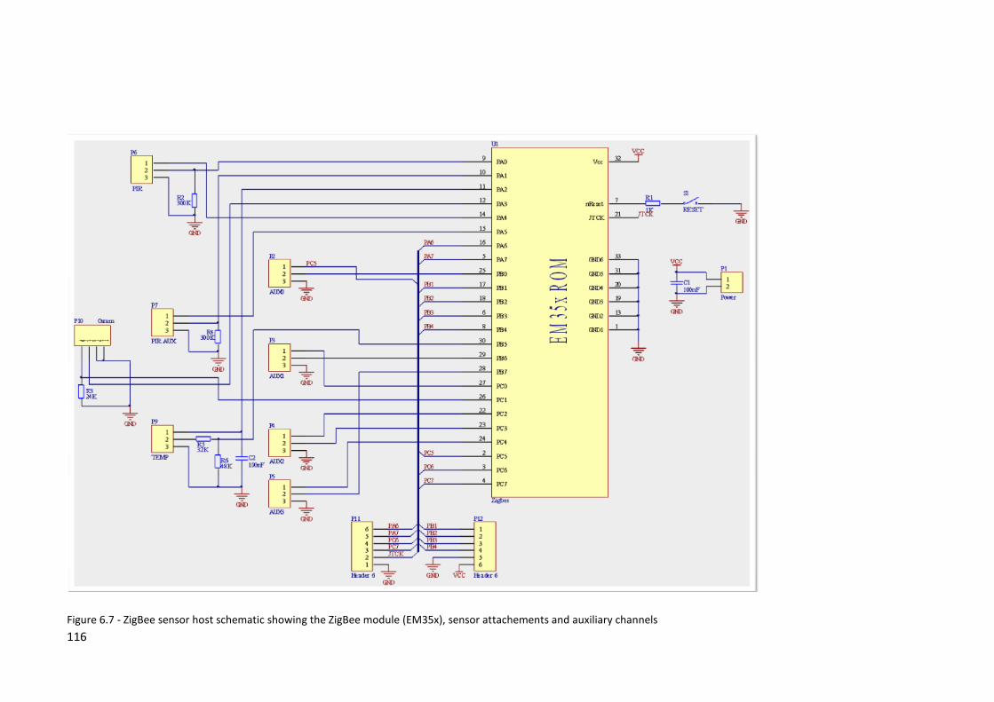
116
Figure 6.7 - ZigBee sensor host schematic showing the ZigBee module (EM35x), sensor attachements and auxiliary channels

117
After initial evaluation with the Veroboard prototype, a printed circuit based prototype was
developed and is shown in the top left of Figure 6.8. Some small changes were made, mainly
layout changes to accommodate easy fixing to ceilings and 12 units were then produced
(Figure 6.8, right). A typically ceiling deployed unit is shown in situ in Figure 6.9. Each unit uses
two AA batteries (weight approximately 30g) as the power supply and measures approximately
60mm x 40mm. The (white ‘Molex’) connectors allow the connection of additional sensors and
actuators to the spare channels. More details are given in appendix A. A realistic estimate for
the total unit cost in a small production run is £35.
As well as low power consumption, a main consideration when selecting the ZigBee unit was
the provision of commands to allow fine grained control of the peripherals and input / output
channels attached to the wireless host, while offering good ‘ready to go’ wireless network
management, without the need to immediately perform embedded systems development. The
Telegesis range offered that, while still permitting custom development of the ZigBee stack
functions later if required (see section 8.3).
Figure 6.8 - ZigBee sensor units, PCB before population, first PCB prototype (top left), and the
demonstration units

118
Figure 6.9 - A (typically) ceiling deployed ZigBee sensor host
6.2 Agent Development and Implementation Specifics
After presenting a summary of the IFMS agent types in Table 6.2, the discussion in this section
focuses on the salient development and implementation details of two main agent types,
namely the zone and senor node agents. The other agent types such as the utility and facility
manager agents are not central to the framework so are only reported at an overview level of
detail. The IFMS agent layer deployment is shown in Figure 6.10.

119
Table 6.2 – Summary of the IFMS agent types
Agent type Summary
Zone Agent
Generates zone centric knowledge by building and elaborating its domain
beliefs
Sensor
Node Agent
Controls the (finite) provision of resources, reconfigures devices dynamically to
minimise power consumption while satisfying monitoring provision. May refuse
or substitute resource provision. Resource provision is sought from wired and
wireless sensor networks accessed via IIOP protocol endpoints
Yellow
Pages
Agent
A broker. Maintains agent type registry, and agent specific services e.g. sensor
node resisters sensor GUIDs. Responds to agent related service queries. Allows
other agents to find agent host given space id, selection criteria, find sensor
host. host a lookup service for agents and some agent meta data
Utility
Agent
Mainly used for testing the framework and for analysis of performance of goals
used by other agents e.g. leases mechanism. Also performs simple rule based
data logging
Facility
Manager
Agent
Issue goals. Retrieve selected beliefs from zone agents. Has application for
agent lifecycle control and configuration. Not deployed in testing

120
Figure 6.10 - The IFMS agent layer deployment
6.2.1 Zone Agent Development and Implementation Specifics
This sub section describes some details of the zone agent type’s implementation. Table 6.3 provides an
overview of the zone agent type’s goals. The scope of the table’s contents does not include deliberation.
Where the JADEX ADF configuration settings were adequate to realise deliberation, which was generally
the case, that mechanism was used. For more complex deliberation, while a meta goal mechanism is
available via the ADF, a slight variation was preferred and is described in section 5.2.1.2. An example of
more complex deliberation involving an intermediate (high level) goal is the deliberate occupancy
evaluation goal and is outlined in section 6.2.1.2.1.

121
Table 6.3 - Zone agent goals summary
Goal Responsibility Notes
Initialise Read configuration file Configure agent and zone identity, message
routing info
KB management Populate building ontology
KBs
From IFC model cluster and individual
sensors are extracted and those of interest
are elaborated into the KB
Infer zone classification
Infer monitoring capability
Infer roles for sensors Allocate sensor roles
Accumulate ‘experience’
Evaluate
occupancy
Determine / count
occupancy
Detect if the zone if occupied / unoccupied
or maintain a count of the persons
occupying the zone. A number of
alternatives goals can be dispatched. See
section 6.2.1.2
Identify wasted
resources
Attempt to determine if lighting or heating
has been left activated. Primarily compares
current and previous environment summary
and evaluates for lighting level transitions.
Some assumptions for heating over longer
intervals are also used as criteria. Can also
use ‘learnt’ beliefs if available for a similar
earlier context.
Monitor key
parameters
Manage leases, update
internal environment
beliefs with added context
aligned with occupancy
change
Trigger at zone occupancy change. Sample
at regular interval e.g. 5 mins., temperature
and ambient light. On plan completion
generate some simple statistics. Use
inference to select ‘representative’ devices
Locate resources determine host using YP agent
Resource
management
Request leases Base plan class implements: lease creation
and formulation, message formulation,
interpretation of reply. Override specifies
devices to request leases for. Requested in

122
advance of activation where possible
Verify leases / subscribe Override implements verification and
generation of ‘explanation’ code for failed
verification
Summarise zone Evaluate beliefs With comparisons to absolute values and
learned values for expected internal
environmental conditions, and occupancy,
formulate statements about unexpected
conditions
Verify occupancy SL message formulation,
dialog
Attempt to verify an occupancy change.
Verified if the occupancy change is confined
to the two zones sharing a given opening, so
involves determining if the occupancy of the
neighbour’s neighbours has changed in a
given interval
Collaborate
(client)
Find agents Using message dialog, find the host agent
for a given device, device type etc.
Request data Formulate SL message and dispatch, process
reply
Listen for subscribed
notifications
Process notifications for active leases,
create internal events to notify active plans
and provide short term buffer
Verify occupancy/counting
with neighbour
Request occupancy/count
Collaborate
(server)
Register with YP ‘advertise’ self so that other zone agents
can initiate collaboration.
Listen for requests Listen for (SL message or other) requests,
and formulate reply
Subscribe collaborators
(sensor nodes, zone
agents)
Manage other agents request for
notification (subscribe) of occupancy count
and zone monitor occupancy mode
Listen for notifications and
handle notifications
Listen for request for occupancy count, zone
monitor occupancy mode, commitments
and reply to request with appropriate
message formulation. Uses Java object

123
serialisation for commitments, otherwise
uses SL
Event handling Listen for events Process notifications (for held leases)
Request leases Formulate leases, find device hosts, prepare
and dispatch SL message to appropriate
host
Evaluate
occupancy using
environmental
state and history
Correlate environmental
conditions with usage to
identify unnecessary
heating and lighting
Attempt to use existing beliefs, historical
beliefs and current observations to
determine occupancy. The plan checks for
several scenarios including a significant step
transition in lighting levels and temporally
‘close’ boundary activity. Another is the
check for no activated artificial lighting after
the hours of darkness that could indicate
that a zone is unoccupied. Assertions are
not made until other factors that increase
confidence such as previous similar
observations, characteristic Lux levels etc
have been ‘learned’. Conclusions are initially
tagged as ‘candidate’
The occupancy evaluation sub goals listed in Table 6.2 are described in more detail in section
6.2.1.2. Occupancy evaluation illustrates typical BDI agent behaviour and is central to the
agent’s main motivation to derive zone based knowledge. Occupancy evaluation is a central
goal because several other goals trigger from or consume its conclusions.
6.2.1.1 The Zone Agent’s Ontology Use
The use of ontologies is central to the zone agent type’s operation and is mentioned
throughout the following sections. In general though the agent maintains two types of KB
employing the buildings ontology, which imports the sensors ontology, reflecting ‘as given’ and
‘as is’ models of the environment. The former reflects the ‘designed’ or ideal state of the
environment where all the sensors specified are available and includes no learned knowledge
about zones, either about its own or about other zones learned from neighbours. The ‘as is’
model is synchronised with knowledge collected from the environment including sensor lease
states, asserted and inferred knowledge about its own zone, and about other’s zones. The

124
latter includes knowledge derived from requesting other agent’s beliefs and intentions such as
monitoring mode. Low level sensor events are not added to the A box for performance
reasons.
The development of ontologies for the support of deliberation and means end-reasoning for
the main agent types is described in section 6.3.
6.2.1.2 Illustrative Goal Implementation Detail - Evaluate Occupancy
The ability to evaluate occupancy is a central high level goal of the zone agent type. It is
described here in detail to illustrate the application of several of the common patterns used by
agents in goal solving. The realisation of deliberation for that goal is described first, followed
by description of a range of plan implementations. Those implementations realise means end
reasoning leading to actions in the plans in order to realise the (sub) goal. A summary of the
sub goals are present first in Table 6.4.

125
Table 6.4 - Evaluate occupancy sub goal summary
Description Goal Key features Hardware
requirement
Dec / unoccupied Inc / occupied Cause of unresolved
scenario/s
Determine
occupancy
retrospectively
triggered by barrier
sensor
Determine
Occupancy
Only works retrospectively,
working back from the BS
activity so appropriate historical
lease coverage is needed thus
suited to wired devices. Fairly
robust
IMS + BS. Optional
environment sensor
may increase
performance
Any BS activity
followed by asserted
lack of IMS ->
unoccupied
Any IMS activity ->
occupied
Propped opened door when
the BS is a proximity switch.
IMS/s inadequate internal
coverage of zone – use
standard or wide angle PIR
type to maximise coverage
Determine
occupancy by
monitoring
openings
Determine
Occupancy
Readily deployed ZigBee sensor
cluster i.e. avoids constraint for
barrier sensor
(OMSI* or OMSO*)
+ IMS. Optional
environment
sensors may
increase
performance
(OMSI or OMSO
activity) followed by
asserted none IMS ->
dec
(OMSO or OMSI
activity) followed by
IMS -> inc
A range of scenarios
connected with different
human activities are
accommodated but some are
not see section 6.2.1.2.2
Count occupancy by
monitoring
openings
Count
Occupancy
Desirable as hardware readily
deployed, particularly using two
motion sensors, and that suits
well virtual openings. Magnetic
sensor on door fairly robust in
role of OMSI or OMSO
(OMSI + OMSO*),
or (OMSI* +
OMSO)
OMSI activity
followed by (OMSO
activity or related
entry to neighbour ->
dec
OMSO activity
followed by (OMSI
activity or related exit
from neighbour -> inc
If more than one person
leaves or arrives at the same
time may mis-count
Potentially Check No sensor hardware required BS and adequately BS followed by entry BS followed by exit Multiple occupancy changes

126
determine or count
occupancy without
internal hardware
opening inside the zone. Adequately
committed (all) neighbours
determine which if either
determine or count is possible
committed (all)
neighbours
to neighbour when
no other occupancy
change of that
neighbour’s
neighbours -> dec
from neighbour when
no other occupancy
change of that
neighbour’s
neighbours -> inc
in related/active neighbour’s
neighbour/s, or inadequately
committed neighbour/s
Generates entry /
exit to / from c.f.
occupancy
Monitor
thoroughfare
Asserts unoccupied. Tracked
motion indicates occupancy
At least two IMSs Track ‘finalisation’ Track initiation –
retrospective (after
‘finalisation’)
Sensitive to non ideal human
behaviour e.g. pausing,
variation in walking speed.
The sensor roles are:
Opening motion sensor inside (OMSI) – covers opening and may cover internal motion, OMSI* covers opening only. Nominal inside, can be outside the
zone but describes the first activation on exit detection.
Opening motion sensor outside (OMSO) – covers opening and may cover internal motion, OMSO* covers opening only. Nominal outside, can be inside the
zone but describes the first activation on entry detection.
Boundary sensor (BS) – covers door and excludes internal motion, e.g. door proximity switch, restricted view PIR (spot or shaded type). Such sensor
classifications can be asserted or inferred e.g. due to placement. Role can be filled by (OMSI* or OMSO*)
Inside motion sensor (IMS) – detects motion inside the zone

127
The determine occupancy goal detects if a zone is occupied or unoccupied by persons, while
the counting goal attempts to count the number of persons inside the zone.
The roles are assigned when the goal starts. The agents will re evaluate the roles each time the
goal restarts, and so if the current assignment causes the goal to fail, the goal will be dropped
and restarted, at which point the roles are re evaluated. Neighbours are those directly
connected via any opening e.g. doorway. The multiple potential occupancy of zones is
assumed. The coverage role for internal PIR / external PIRs (OMSI and OMSO) is captured by
the ontology with the relations ‘inProximityOf’ and ‘observes’. Thus the OMSI* and OMSO*
roles can be assigned to sensors participating in ‘observes’. The ‘observes’ relationship is
assigned to sensors and openings based on a suitable semantic description of the sensor as
well as other geometric constraints.
A generalisation about the occupancy evaluation goals (and other goals that utilise sensors)
regarding sensor utilisation is that benefit is gained through the use of a range of sensors in
contrast to a single or smaller number of devices. The utilisations are matches of numerous
specific roles within the devices’ operational constraints including their sensing capabilities
and deployment. In contrast if a smaller number or a single sensor was used then the
suitability of the role matching would be more of a compromise.
6.2.1.2.1 Deliberation and Means-End Reasoning for Occupancy Evaluation
The implementation of deliberation for occupancy evaluation follows many of the aspects
outlined in the principles of implementation above. The zone agent type’s occupancy
deliberation is depicted in the UML activity diagram in Figure 6.11 and Figure 6.12 The diagram
does not capture the allocation of activities to sub goals and while still containing some flow
control, it is simplified to illustrate some salient scenarios. Initially the feasibility of options is
determined.

128
Figure 6.11 - Occupancy deliberation in the zone agent type

129
Figure 6.12 - Occupancy deliberation in the zone agent type (cont'd)

130
Occupancy deliberation starts by the collection of salient knowledge form neighbouring zone
agents. First the agent and zone identifiers of registered zone agents are requested from the
yellow pages agent (each zone agent resisters its agent and zone identifiers together with
other information). Then for those zones of interest, using the agent identifiers in turn, the
occupancy determination commitment from those neighbours are requested. The zone
identifiers of interest are inferred using the ‘as given’ ontology KB, and that information
returned by those neighbouring agents is synchronised with the same KB. The KB’s building
related information is maintained from agent start-up by parameterisation of the IFC ‘load’
goal so that semi static ontology content update is not repeated unless necessary. The next
feasible candidate occupancy monitoring mode alternatives are then compiled from the
inferred zone classifications for the zone of interest from the ‘as given’ KB.
Those modes are next ordered according to preference. The preference is derived from the
following considerations:
Preferred quality of goal e.g. counting preferred to presence determination where
possible
Hardware utilisation
Characteristics of goals such as
o Lead time e.g. having to wait for non occupancy evidence
o Some goals take longer to evaluate conclusions e.g. assert that no motion has
occurred for an extended time
o Dynamic dependency on provision of knowledge by other agents (some
dependencies are captured in feasibility but for example ad-hoc collaboration
is not, and instead the agent relies on the audit mechanism to capture earlier
failures)
Reliability and sensitivity to errors
The probability of not running monitoring due to having to perform reset sequences
and other factors
Some of the characteristics above are interdependent. The capture of preference in the
implementation incorporating the contributing influences is implicit though and mostly static,
although some meta data is available from plans that describe state durations for example and
abstract descriptions of resources required can be retrieved (but it is only during means-end
reasoning that specific sensor roles are assigned). Regarding preference for occupancy
evaluation in isolation, the general order is: count <- determine <- check opening use <- no
occupancy determination. A few dynamic influences adjust the order and modify it e.g. the

131
removal of the counting goal during ‘out of office’ hours. Moreover from a dynamic
perspective, several of the influences listed significantly but indirectly affect the deliberation
outcome earlier during historical behaviour analysis.
Next in deliberation the historical performance of earlier behaviour is evaluated. Reviewing
the audit for similar behaviour to each option, the implementation filters out options by
applying some simple criteria defined by some constants that capture various ‘influence
durations’ and retry counts. The first of the ordered remaining occupancy modes then
becomes the occupancy determination deliberation outcome and any remaining others are
neglected.
The outcome of deliberation in general sets a number of plans but those plans are either of the
determine or count occupancy type i.e. goals can be mixed but share the same occupancy
evaluation type. The deliberation choices are mapped to zone inferences. The zone inferred
monitoring classes are defined in terms of statements relating to geometry, sensor provision
and other beliefs about the zone and about neighbours’ zones. Some statements derived from
collaboration, as well as those the agent makes itself, are dynamic and in some situations serve
to ‘elevate’ the occupancy evaluation capability type. For example a neighbour space may be
inferred to be a room containing plant that is rarely accessed, or there may be just adequate
hardware to detect activity at that opening, so the agent can for example count while that
opening has no associated activity.
After deliberation, means-end reasoning then attempts in plan implementations to identify
how the associated goal can be satisfied, typically with further reasoning and further action.
Inferences are again used, this time in the ‘as is’ buildings KB, to determine the practicality of
the occupancy monitoring goal (type) being perused by a given plan, and also for the
assignment of sensor roles. The inferences are deduced from assertions of sensor availability
derived from verified leases, as well as statements derived from neighbours’ beliefs and
commitments (via requests for their relevant attitudes, followed by synchronisation with the
‘as is’ KB). In the case that no inference is reached to indicate that the plan is practical, after
updating the audit with that fail status the plan exists.
In summary the occupancy evaluation algorithms show diversity in their capability and in their
implementation. Deliberation to select the most appropriate relies on the semantic analysis of
the context (building configuration, sensor types, sensor availability and sensor locations),
collaborative knowledge and its past performance. Appropriate repeated deliberation realises
appropriate agent behaviour within the dynamically changing environment.

132
6.2.1.2.2 Determine Occupancy
The determine occupancy plan implementation detects the presence or absence of people
inside a zone. The determination that a zone is unoccupied forms a key basis for the
determination of wasted resources. A characteristic of the plan is that it can be relatively
efficient in terms of resource utilisation at monitoring extended non occupancy, such as that
likely to occur ‘overnight’ in a typical office zone. Also good efficiency is achieved if occupancy
is asserted soon after the state change into the determine occupancy state, as then some
hardware resources (via leases) can be dropped. The addition of further sensor selection
criteria (in addition to role’s functional and context requirement) that considers immediacy of
device availability was considered, but the typical benefit was not clear without further
investigation (see section 7.3.4.3). The SPARQL query for the sensor role section is expressive
but compact and includes capability and type specification, as well as details of the host
provision, in addition to context related criteria definition. The commitments mechanism (see
section 5.2.2.1) facilitates the use of existing (active) devices leases in other plans / roles.
As well as for the assignment of sensor roles, the use of inference in the determine occupancy
plan includes the time based parameterisation of the algorithms in the plan. For flexibility
algorithms refer to relatively abstract classifications of opening and boundary sensors but
detailed configurations (specifically time related settings) are mapped to specific inferred
types to improve the plan operation e.g. the exit suppress event interval for a physical door.
The state machine design of the plan is shown in Figure 6.13. On entering a new state, the
appropriate resources are requested and verified using the pattern of implementation outlined
in section 5.2.1.4, with method overrides for each state that define the resources and the
verification implementations. After an appropriate interval of no occupancy change, the plan
reverts to the determine occupancy state to verify the current belief.

133
Figure 6.13 - Determine occupancy state machine
6.2.1.2.3 Count Occupancy
In the occupancy counting plan, in common with other plans, the sensor role selection is made
from semantic knowledge. For each opening in a given zone, the algorithm uses a number of
SPARQL queries that extract semantics about sensor relationships to the building (context),
and sensor domain knowledge. A number of queries are used to satisfy different scenarios,
and each query assigns orders of preferred alternatives, if any, to each role. In a few cases due
to ‘quantisation’ inherent in some of the object relationships, the algorithm may extract
geometric information from the IFC model in order to resolve any ambiguities (see section
7.2.4.3).
The counting plan is realised by a simple state machine which has an initial state to determine
that the zone is unoccupied, and thus can set counting to zero. A number of sub goals are used
for that purpose, including the plan which attempts to infer zero occupancy without using
motions sensors. If that fails then the agent uses another goal which assumes zero occupancy
after an extended interval of no detected motion. When a zero count has been established,

134
the plan instantiates for each opening in the associated zone, an object that determines the
direction of movement of persons through those openings. That class, the entry / exit tracker is
described in the next sub section.
6.2.1.2.3.1 The Entry / Exit Tracker Class
The entry / exit tracker class performs the task of interpreting (boundary related) events, and
determines from those, the direction of movement of persons through the associated opening.
The class implementation relies on a state machine (Figure 6.14) to realise its operation. In
order to handle the nature of event updating, where events can arrive in blocks, and the fact
that events associated with one episode (a delimited collection of events generated by a single
entry or exit) can be spread over more than one block, the class buffers events in collections
and analyses those collections. Aligned with the nature of motion events (see section 6.2.2),
the implementation primarily relies on the leading events associated with an episode but also
employs several other algorithms that were developed during deployment evaluation (see
section 7.3.4.2). The generated entry / exit events are defined from the episode start and an
approximate duration. In connection with the approximation for duration, agents apply a
tolerance window when negotiating over occupancy change involving such events.
Figure 6.14 - Entry / exit tracker state machine

135
The state machine creates the entry / exit event definitions on exit from the determine state as
shown. Those events are added to a buffer which the plan soon retrieves and updates its
occupancy beliefs appropriately. On recognition of ambiguity in counting, the plan aborts
rather than resets. Therefore control is shifted to deliberation to potentially reinstate
counting, or to revert to another plan. Additionally plan failure can result from lease
verification failure as well as other run time errors.
The class has several parameters that are configured using semantic information derived in the
configuration stage. Those settings improve the robustness of the class’s operation, and some
of those details are described in section 7.3.4.2. The count occupancy plan, like other plans
overrides base plan methods in order to realise lease management for the tracker instances,
and maintenance is carried out on a time triggered basis.
6.2.1.2.4 Opening Checker
The opening checker goal and plan implementation caters for the scenario where a zone has
inadequate hardware to adopt either the counting or determine occupancy goals, but is able
to check an opening for activity, typically with a single sensor. Under some conditions e.g. no
opening activity for an extended interval, the agent using this goal can make some occupancy
assertions about the zone. Via collaboration, these assertions can also reduce the sensitivity of
lack of some hardware to other agents’ goals. It is the least desirable goal however that an
agent will adopt under the evaluate occupancy top level goal. Other situations can cause this
goal to be adopted after appropriate deliberation has concluded that, for example, other goals
have failed due to for example unverified leases for hardware.
Regarding occupancy evaluation however, the plan is able to use a sub goal for collaborative
verification of occupancy, and thereby attempt occupancy determination or counting on a
more immediate and consistent basis than the scenario outlined above. First though, like the
other plans, a reference state is asserted using the same sub goals or overridden methods.
After the zero occupancy has been asserted, the verify occupancy sub goal can be invoked on
detection of boundary activity for the purpose of possible occupancy evaluation. That sub goal
requests from the neighbour that shares the ‘activated’ boundary, its current and recent
occupancy count change recent history (which also captures the determine occupancy goal
outcome in the form of ‘count greater than zero but not numerically defined’). The plan then
attempts to verify if any of the neighbours’ neighbours reported occupancy changes, and in
the scenario that that was not the case, then an appropriate occupancy change can be
evaluated for its own zone. The ability for counting or determination is dependent on the

136
neighbour’s occupancy evaluation mode. However the ‘own zone’ occupancy evaluation
aspect of this plan has not yet been tested in a deployed system.
6.2.1.2.5 Continuous motion occupancy detection/count
The continuous occupancy evaluation plan makes the assumption that, if it is occupied, then
persons inside the zone can be assumed to be in continuous motion. During deliberation, an
agent will adopt this goal based on a threshold aspect ratio (approximated to a containing
bounding rectangle) and the existence of more than one opening. Such zones, typically
thoroughfares, can also lack furniture containment but that is not used as an adoption criteria.
The occupancy beliefs of thoroughfares are potentially useful in supporting other agents in
collaboration.
The plan implementation involves the management of event collections (TrackerNode class)
for each motion sensor in the track between zone openings, realised by the MotionTracker
class. Estimates for the time of transit between the detection ‘points’ are estimated from the
sensor separation and typical walking speed. The algorithm then executes forward and
backwards searches, where the search attempts to find an event in the next TrackerNode
object inside a time interval generated from each candidate event using the time window
estimates. Any events are added to a newly created Track object. The search continues along
the track (an instance of TrackerPath) until no candidate fits the window criteria, or until the
nominal end / start TrackerNode object is reached, in which case a event is constructed
describing a nominal track ‘exit’ or ‘entry’. If the internal MotionTracker determines that
existing partial tracks have exceeded the last update (timed-out) then a standard entry or exit
to the path is deduced and a standard track instance is created. Such standard tracks typically
occur when a person leaves / enters the tracker path via a virtual boundary. The deployment
has only been evaluated in the domestic flat test deployment, primarily because the
deliberation has not yet been implemented to activate this plan in conjunction with others.
Variables which affect robustness are triggering characteristics of motion sensors and the
range of walking speeds accommodated, as well as behaviours of persons such as pausing to
activate light switches, and persons walking in groups.
The leases for the participating devices are managed by appropriate method overrides and
base plan functionality, similarly to the other occupancy evolution plans.
6.2.1.2.6 Evaluate Occupancy without Motion Detection
A goal, typically dispatched by an agent as a sub goal, has been implemented as an alternative
to the goal that uses the detected lack of motion over an extended interval to make the
assumption of zero occupancy. This goal instead attempts to assert zero occupancy without

137
the use of motion sensors, thereby delivering a potential conclusion with minimal resource
usage and in a short time interval. One premise is that a zone is unlikely to be occupied if it is
a working area or ‘living room’, with no activated artificial lighting after the hours of dark. The
evaluation depends on an adequate learned lighting level for such scenarios. Due to the pre-
conditions (of the algorithm cf. goal), the outcome of this plan in practice can be inconclusive.
6.2.2 Sensor Node Agent Development and Implementation Specifics
This section discusses some details of the sensor node agent implementation. The primary goal
of the agent is to deliver resource provision in terms of monitoring data to other agents that
request it, while managing efficiently that provision, especially in the case of finite resources.
The battery powered wireless sensor units managed by the sensor node agent have a finite
power source and the system (but primarily this agent and benevolent clients) aims to
maximise the interval between those battery replacements. The device lease class plays a
central role in dialog between agents relating to resource provision, and is described below.
The BDI model is exploited though the adherence to the pattern of application identified in
section 5.2.1. A summary of selected high level sensor node agent goals is given in Table 6.5.
Table 6.5 - Sensor node high level agent goals summary
Goal Responsibility Notes
Initialise Read configuration file Configure agent identity, message
routing info
Manage
infrastructure
node connections
Discover infrastructure nodes Periodically poll the known endpoints
for new resource availability. Maintain
‘active nodes’ list
Extract sensor events Poll active endpoints for (infrastructure)
events
Advertise sensors Register services with YP
Retrieve resource list
Manage clients Listen for subscriptions, sensor
lease requests, general
requests
Interpret SL message
Subscribe client maintain lease subscriptions lookup
table
Collaboration Register with Yellow Pages
(YP), Advertise resources in YP
Register agent type, associated zone
identifier, hosted devices, with the YP

138
agent agent. Refresh on any change
Describe resources/sensors Elaborate descriptions using the sensor
ontology for rapid data response from
clients. Triggered on addition of new
knowledge of devices
Service requests Reply to data requests after verifying
lease status. Request data from
infrastructure (sensor read)
Notify subscribers Formulate SL message and notify lease
holder of new data
Negotiation Manage sensor leases
Wireless network
management
Configure wireless nodes,
configure individual sensor
channels and manage power
settings
Serve sensor lease requests with
wireless sensor node availability,
minimise power consumption of nodes.
Manage networks (configure nodes and
sensors)
Manage wired
networks
Monitor sensor availability Grant leases for available devices
6.2.2.1 Application of Ontologies Summary
The sensor node agent type makes extensive use of the sensor node ontology to support
means-end reasoning and some deliberation. Similarly to the zone agent type, the sensor node
agent creates and configures a number of different KBs for use in different reasoning
applications. A non inference configuration is used for population of the A box. The use of
RDFS inference offers much shorter inference delivery for event identification, relying on
limited expressivity compared to the application of full OWL inference rules. A Pellet inference
supported KB is also configured and is widely used for general full expressivity reasoning.
Typical applications of inference are to analyse the connection of a given device in order to
determine the handling of lease requests, to evaluate the power mode for the host node, and
to elaborate sensor clusters to find connected channels and devices. Additionally the
connection topology is analysed for other characteristics such as connection to a mains
electrical outlet (thus not battery powered) and other queries involving the T box, or to
determine if a device is wired or wireless. The use of abstraction describing sensor type and

139
mesurand characteristics is not so extensively used as clients typically request specific sensor
individuals i.e. that role is usually completed by client agents.
6.2.2.2 Service Provision
In support of the sensor node agent type’s primary goal to deliver requested sensor provision,
the agent performs several other high level goals in support of that. Those goals involve finding
infrastructure resources, identifying the resources available (in order to ‘advertise’ to other
agents), as well as managing those resources efficiently. Although the infrastructure
components have default behaviour, the lack of intelligence in that layer means that the
sensor agent has a central role even when no resources are requested by clients, particularly
regarding the wireless hosted resources. The implementation of simple default behaviours in
the wireless network was a necessary design decision made in order to reduce redundancy and
possible conflict.
Effective sensor node agent behaviour relies on the sensor ontology KBs in order to direct
actions in the plans (means-end reasoning), as well as on the algorithmic implementation of
plans.
The dialog over resources is based on a sensor lease class as mentioned which facilitates
requests and allows verification of status. The lease class is described in section 6.2.2.3. The
lease lifecycle is dependent on the wireless network status and success of the sensor node
agent’s actions. In general node and device configurations are not actioned immediately. The
sensor node agent can modify the lease interval requested, and is able to select the device
that fulfils the lease from a number of alternative devices the requestor has nominated.
Alternative selections are granted depending on availability of the device and its host.
The agent manages some meta data relating to devices and their activation. For example a
device activation history is maintained that is used to implement signal conditioning to
suppress spurious transient signal generation that are characteristic of some sensor types
when they are first powered on, particularly PIR devices. For that purpose ‘suppress’ intervals
(derived from datasheets) are mapped to abstract types. Other meta data is managed for
wireless network nodes.
6.2.2.3 Device Leases
The device lease class when used as the content of SL expressions in inter-agent messages
plays a central role in realising resource negotiation and verification of status. The lease
resolutions and states are

140
Resolutions: None, Initialised, Pending, Granted, Delayed, Denied – determined by
device availability
States: Active, Inactive – set by the start and end times
In the case that a given requested device is attached to a node that is available in the network,
following successful node and device configuration of wireless devices, or without further
action for some wired devices, the requested lease will be assigned the granted resolution. If
the node is not available or the configuration fails for another reason, the lease is assigned as
delayed. The resolution is also assigned as delayed if meta data is held stating the node is
currently unavailable, and in that circumstance the configuration action is not attempted.
Those leases with a start time later than the current time are assigned the pending resolution.
If the host is not recognised, the lease is set to denied state.
Regarding the setting of the duration of leases requested, typically very short leases are used
to ‘sample’/ read a value, while longer durations are used to ‘subscribe’ to, and thus receive,
asynchronous notification of events such as motion and switch activation. Regarding the
timing of issuing lease requests, client agents that employ scheduled reading can request
leases in advance to allow lead time for activation. Another temporal consideration regarding
leases on a shorter time scale is that some sensors require an interval for circuit for
stabilisation as mentioned above in connection with signal conditioning. As an example a
device that has a relatively long stabilisation time is the ‘Napion’ motion sensor range at 30
seconds.
6.2.2.4 Device Management
In order to deliver the best timely responses to new leases, the sensor node agent attempts to
action newly requested pending leases immediately. Some leases can be granted without
further action as mentioned, such as those for wired devices, or those leases which are
requested for sub intervals of those already active. Next, if a compatible active lease exists the
agent extends it. If the lease requested is for a wireless hosted device then the agent then
initiates wireless network management.
Regarding the management of wireless networked resources, the agent has the role of
assigning behaviours defined in the infrastructure implementation to wireless nodes, and
configuring the devices attached to the hosts appropriately. Those devices are both actuators
and sensors; the actuators control the power to sensors. The node behaviours (see Table 6.1)
are mapped to certain sensor KB inferences and so when appropriate i.e. it is inferred that a
request for a new resource requires a different node behaviour to the existing one, that node

141
behaviour set command is issued before the device configurations are issued. Those node
behaviours assign configurations for ZigBee node devices such as its radio components, timers,
and timer activation of preset actions for example for network management, resulting in
characteristics such as power consumed, sensor availability, and sensor availability ‘lead time’.
The target host node availability is dependent on its current configuration (behaviour), or
there may be other reasons for its unavailability such as an expired power source.
From the range of node behaviours available, the sleep-and- listen mode is very desirable for
assignment to nodes that have no active leases for hosted devices, but it is not commonly
used. One reason for not using that mode extensively is due to lead times in availability,
particularly where there is little redundancy in device roles from the client agent perspective,
and given that typically clients assign and change roles in a very dynamic fashion. The purpose
of the device meta data though is to track the configuration of nodes, exemplified by the case
where a node is not available to retrieve its status. Another factor is that before activation of
the sleep- and-listen mode, the agent has to ensure that as well as a feasible electrical
configuration for waking the device is available, there is also a feasible physical scenario. An
undesirable situation is if a node was put into this power mode and the wake up scenario was
rarely encountered e.g. motion detection in a rarely assessed room.
In contrast to ‘on demand’ node management, the agent performs routine network
management where devices with associated expired leases are powered off, and host nodes
are put into a standby mode when possible. Several power settings are available and settings
are described in more detail in section 6.1.3. The power modes standby and low power are the
most commonly used modes.
6.3 Ontology Development
6.3.1 Introduction
This section describes the artefacts produced to realise the IFMS knowledge support, the latter
motivated by the factors outlined in section 4.2. Several ontologies were generated following
the workflows described in section 4.3.3, primarily guided by the Neon methodology. The
application of the methodology is straightforward so is not described in detail. Instead this sub
section, after describing the main features and scope of the domains, presents some detailed
design principles of the ontologies. Next the different ontology artefacts are described in
detail, covering the rationale for some of the design decisions. A focus of the discussion is the
application and exploitation of those knowledge resources by the IFMS.

142
6.3.2 Overview
Several ontologies support agent behaviour in the IFMS. The ontology set has been developed
to fulfil very specific roles in its specialisations, building on domain independent semantic
models and encapsulated theories.
The ontologies developed for use in the framework include:
A building ontology capturing the building geometry and assembly. The origin of the
taxonomy was the IFC. Theories of topology and mereology have been integrated.
The sensors ontology describes the sensor devices in terms of the phenomenon that
they capture, their detection capability and associated platform configurability. The
origin was an ontology called OntoSensor, which in turn is based on schemas in the
SensorML modelling language.
A general purpose ontology, SUMO that captures domain independent concepts.
Although in the IFMS some central concepts inherit from SUMO entities, a large
proportion of the provision did not find useful application.
The system ontologies, their source resources, and their interrelationships in the sense of
referenced terms supporting modelling, are shown in Figure 6.15.

143
Figure 6.15 - IFMS ontologies, interrelationships and dependencies
The direction of the arrows in Figure 6.15 show the derivation of ontologies from various
resources. Typically OWL ontologies (green) were derived from the resources, and use the full
expressivity of the OWL language. However the dialog ontology’s main role is for use as a Java
based representation for the capture of agents’ message content. The ontology is a light
weight representation of the content of the other IFMS ontologies, allowing the agents to
exchange beliefs and other attitudes. The figure illustrates the relative sizes in terms of the
number of concepts, roles and other axioms. Overlapping areas are manifested by the linking
of concepts.
6.3.3 Common Design Principles
In the area of fundamental formulation, Fielding, et al. [82] identify the classifications of
“endurants and occurrents”, “dependent and independent” and “universals and particulars”.
In SUMO the separate high level entities object and process reflect the temporal distinction
captured by endurants and occurrents (defined in section 2.2.7) for example. The authors’
dependency classifications describe the necessity for existence of membership of a whole e.g.
the concept of door function relies on a door and other entities. The criteria of universalness

144
make the distinction between type or class and individual or instance. Those classifications and
associated properties were taken into account throughout the ontology implementation.
Another general ontology design consideration was that of semantic closure, arising as by
default OWL semantics adopt the open world assumption (OWA). The assumption though suits
the nature of the domain and the KR used to model it. The relatively high KR expressivity
allows rich semantic expression, so a complete model may be unnecessary, or it may be
impractical or impossible to capture. The application of the OWA means that incomplete
knowledge can still be consistent. However there are areas which in contrast are complete and
so explicit closure with appropriate axioms can give additional useful inference e.g. the sensor
ontology states that an enabled and fully functional passive infra red (PIR) sensor signal
indicates movement, so closure indicates no movement. However closure is not appropriate in
the relation between movement and occupancy i.e. a room can be occupied even if no
movement is detected. An alternative approach to implementation without using closure
statements is via Pellet’s integrity constraints where axioms can be nominated as having closed
world assumption (CWA) based semantics and thus interpreted as such by the reasoner, for
example using annotation.
A further consideration in modelling OWL ontologies is the lack of the unique names
assumption (UNA). While Pellet has an option to assert the UNA via the API, for compatibility
with Protégé tools and general reasoner compatibility, design time and run time ontology
updating by agents add owl:differentFrom properties (or the construct owl:AllDifferent for a
set of pair wise different) for appropriate individuals. Missing statements relating to UNA and
OWA have a significant negative impact on the ontologies, particularly where modelling
involves statements with universal role restrictions. However other model statements can lead
to the desired intermediate (different from) inferences, e.g. individuals can be inferred as
different through their inclusion in roles having functional properties.
Similarly to software design patterns, ontology design patterns, and specifically logical, content
and architectural patterns have useful application and some were applied, or at least
influenced the ontology implementation. The Neon deliverable [171] describes a catalogue of
patterns. Among the less trivial of the logical patterns are those for modelling: N-ary relation,
exhaustive class (mutually disjoint sub classes), and collections of nominal values. Content
patterns include the participation (modelling the involvement of entities in events) and part-
whole patterns. Rector [172] also describes representing values using “value partition” and
“value sets”, which was applied for example in the description of ZigBee hosts. Additionally
‘anti-patterns’, the application of patterns that result in degrading the quality of an ontology in

145
this context e.g. a naming pattern where the names of descendant classes are not less
abstract, provide useful guidance.
Further ontology authoring considerations, relating to classes were:
The primary structuring of the ontology’s taxonomy is based on the subclass relation
construct. The hierarchy should not model composition relationships, and OntoClean’s
essence meta-property is a useful discriminator. Essential properties are those that
must be upheld, and they persist down the hierarchy.
In order to bring about inferred class membership, i.e. infer new classifications for
individuals, adequate definition of necessary and sufficient conditions for that class is
required.
Creating and naming classes for 'convenience' improves readability and eases
debugging. Such classes are created from the combination of named classes and
anonymous classes (created from intersection, complement, union, restrictions etc)
such as the 'MonitoredSpaceBoundary' in the buildings ontology, where intermediate
inferences are useful to debug the ontology. Inheritance from the convenience classes
is not expected.
The application of multiple class inheritance was mainly run time assertion/s. As
expected the design time asserted class has the rigid meta property (from OntoClean’s
definition, rigidity extends essence in that the property must be upheld in every
situation), while the run time assertions have anti-rigid properties (not essential to all
situations).
A combination of top down and bottom up processes were used to elicit class entities,
depending on familiarity with the area of the domain being modelled. Middle concepts
were elaborated as appropriate.
Further ontology authoring considerations, relating to classes were:
The universal role restriction requires a relatively high count of axioms to support it,
due to the OWA. Closure restrictions and maintenance of the disjoint axioms are
needed. So alternative modelling is preferable if possible. Similarly, in general, the
UNA requires maintenance of different from axioms, in practice the construct
owl:AllDifferent find useful application (see above).
Some constructs when applied to complex properties are nonsensical and / or not
supported. For example, functional or inverse functional properties on transitive roles,
and cardinality restrictions on transitive roles.

146
Typically sub properties were added in order to specify domains and range (the
specification play a role in inference, not constraint), and ‘base’ object properties
retained owl:Thing for the domain and ranges. The motivation was to reduce the
number of undesired and incorrect inferences.
6.3.4 Supporting Ontology Development
The IFMS sensor and building ontologies import a number of common ontologies that capture
domain independent theories and constructs. In particular mereology and topology are
uniformly supported by single artefacts, and in addition further universal concepts and
relations are captured by a nominally upper layer ontology. The upper layer ontology utilised is
a translation of the Suggested Upper Merged Ontology (SUMO) [80]. The OWL translation by
Hendren [173] was used here (a translation was needed as SUMO was developed in a different
KR). The common ontologies promote interoperation between lower domain dependant
ontologies. In practice links are established between concepts in domain ontologies and the
more abstract ones.
A small ontology was created in order to model theories of metrology to capture the
composition of entities. The modelling focussed on physical quantities (components), where
the whole is referred to as a complex in the literature, in contrast to the other wholes of
collections and masses, where the wholes are composed of respectively members and
quantities [32]. A complete ontology of the extensively reported field of mereology was not
required for practical application, so the implemented resource represents a good working
approximation. In the mereology ontology, one base object property is part from classical
mereology that has the transitive characteristic. An elaboration is the distinction of proper part
that captures the exclusion of the whole, hence a sub property properPart was added with the
characteristic of irreflexive. Inverses were also created for those properties. A further sub-
property of part, subcomponent was added with a similar irreflexive property as properPart, but
with the additional specification of asymmetric to capture the sense of super / sub assembly
composition. The irreflexive object property (together with reflexive and asymmetric) is part of
the SROIQ expressivity of OWL2.
An initial implementation for supporting topological theory within the IFMS ontology provision
involved the application of an RCC8 spatial reasoning support. The support was delivered by a
dedicated implementation of Pellet known as PelletSpatial [64] which treats some predefined
spatial relation roles as special cases. These roles capture the topology semantics of the Region
Connection Calculus (RCC), specifically RCC-8 (described in [174]). However it emerged that the
application of the rich semantics of spatial relations could be simplified by using a different

147
design approach, which also released the constraint to use the dedicated reasoner. The
decision was taken that the agent would interrogate the rich and comprehensive geometry in
the IFC for very specific numerical data instead of attempting to capture that for qualitative
reasoning. The topology requirements were adequately scoped to capture connections
between entities such as physically touching and electrical connection. Regarding physical
connection in the context of buildings, the most appropriate was mechanical attachment for
functional purpose. In the context of electrical systems, the ontology captures electrical
connection / link i.e. a power or signal propagation path. A set of object properties were thus
created with appropriate characteristics covering reflexive and direct (non reflexive)
connection together with appropriate inverses.
6.3.5 The Sensor Ontology Development
The requirement for a sensors ontology was the need to semantically model knowledge about
the phenomena sensed by the devices, the electrical and physical characteristics of the sensing
devices and of the supporting infrastructure (including wireless host platforms, interfaces,
connection, power supply), and possibly the some details of the detection processes. Following
Neon’s recommendations and support for developing ontologies from existing resources,
several potential resources were considered for reuse. With approximately 60% of the
concepts identified in the ontology specification for sensors, and due to its OWL formulation
and linking to some SUMO concepts, the ontology OntoSensor [86] was chosen as the basis of
the sensor ontology for the IFMS. OntoSensor is an OWL translation of SensorML [175].
Moreover good documentation is available for SensorML so the rationale for aspects of
OntoSensor can be traced.
Further development of the sensor ontology included the addition of new concepts and some
extra concept linking to SUMO. Straight forward linking is facilitated by compatible structural
characteristics seen in the SensorML specification and SUMO. The main additional modelling
was related to capturing the electrical topology of the ZigBee sensor unit assembly and the
ZigBee host itself such as its built-in peripherals including the analogue to digital converters
etc. The modelling of topology and mereology integrated in domain independent ontologies is
appropriately incorporated by property inheritance. The use of both theories is exemplified by
the resolving of location. While topology assertions / inferences may indicate that a particular
device shares the location of the ZigBee hosted platform, mereology shows that a device
attached via a connector is not part of the unit, so the agent has to determine its position
using another mechanism, typically by interrogating the IFC model.

148
Selected competency questions used in the development of the sensor ontology, in the
context of the IMS, are described in Table 6.6.
Table 6.6 - Selected competency questions for the IFMS's use of the sensor ontology
Competency Question Example application
Find the devices able to detect <phenomena_type> Sensor role selection
Does a given sensor have abstract characteristics given by
<abstract class> and/or abstract <property>
Sensor role selection
Find the sensors hosted by a ZigBee unit given <unique id? Retrieve device details
Find the other sensors that are hosted by the same host as
<sensor id>
Remove duplicate
coverage
What type of network hosts <sensor id> Network management
Is <sensor id> in a wireless network Node management, lease
management
Is <sensor id> battery powered? Node management, lease
management
Are all currently powered devices interrupt driven? Node power mode
Find the channel that connects <sensor id> to the host Node management
Elaborate a cluster Populate the KB ‘A’ box
Find ZigBee unit, given the <unique id> or <network address> Node management
The sensors ontology alone is primarily used by the sensor node agent for dynamically
configuring the ZigBee nodes and attached sensors in the wireless networks, as well as
generally locating resources in order to supply clients with requested data. Constructs to place
the sensors (or other entities) into a context are the scope of the buildings ontology, and for
modelling that context the sensors ontology is imported into the buildings ontology.
A small excerpt of the sensors ontology is shown in Figure 6.16. The figure captures a subset of
the asserted model i.e. no inferences are shown, showing sensor devices and some aspects of
the supporting infrastructures.

149
Figure 6.16 - Excerpt of the sensors ontology

150
6.3.6 The Building Ontology Development
The principal role of the building ontology is to support the behaviour of zone agents in pursuit
of their primary goal of building monitoring. Part of the requirement is, combined with the
sensors ontology, to allow the determination of the type of monitoring that can be carried out
and the selection of the most suitable hardware to accomplish that. The building ontology
adds salient context information to sensors deployed in a building. The building unit for
monitoring is a zone which represents some physical or virtually delimited space, typically
having dedicated function/s. In general zones are delimited by walls or some other
demarcations, and accessed by doorways. Therefore the ontology is able to model zone
boundaries, the ‘makeup’ of those boundaries (topology and mereology of those s well as
other constituent building entities), and the internal environment of zones. Additionally zone
relationships to other zones are captured for the purpose of potential collaboration. Ultimately
the ontology provides sufficient context information for sensor devices, so that the agent can
assign roles to sensors for the pursuit of the different types of monitoring for all the zones of
interest.
The main high level competency questions that emerged from analysis are listed in Table 6.7.

151
Table 6.7 - High level competency questions for the buildings ontology
Competency Question Example application
What types of occupancy monitoring can be performed assuming
all the deployed sensors are available. Monitoring types include
occupancy, temperature, ambient light levels
Deliberation
What type of occupancy monitoring can be performed assuming a
subset of the deployed sensors are available
Deliberation
Find sensor/s with given relationship to building entities (virtual
openings, doorway openings) for <zone id>
Sensor role allocation
What type of zone is rendered by the current sensor provision and
cooperative beliefs about neighbours zone characterisation
Deliberation
Get the boundary sensors for <zone name> / <opening id> Occupancy evaluation
Get the zone characterisation Deliberation,
verification
Find the characterisations for openings of <abstract type> for
<zone id>
Deliberation
Find the sensors inside the zone <zone name>, (<abstract type>) Resource management,
environment monitoring
Find a zone’s openings given <zone name> Occupancy evaluation
Find zone given <zone name> general
Find a zone’s boundaries given <zone name> Occupancy evaluation
Find a zone’s neighbours (sharing an opening) given <zone name> Collaboration
Find a zone’s neighbour given <opening id> Collaboration
The concepts that emerge from the competency questions are primarily spaces, rooms,
doorways, windows and plant such as HVAC. Again following the Neon methodology’s
recommendation for existing resource reuse, the Industry Foundation Classes (IFC) (see section
2.1.2) was identified as a highly suitable. Additionally other resources such as those identified
in section 2.2.8 could be used but due to the higher structure of a taxonomic classification
system, mature status and most comprehensive coverage of the building domain, the IFC was
selected for this work. The IFC has the ability to model building related products and their
assembly, processes (information about the processes to design, construct and manage the
project), resources (resources consumed by the process), and controls (constraints are key to
establishing model integrity).

152
A conversion of the IFC schema to OWL was completed, with the intention of using the
generated ontology as the basis for the building ontology. In addition to its original STEP
representation, the IFC schema has been translated and released in an XML schema language
(specifically XML Schema Definition (XSD)). That translated release, ifcXML [176], has thus
been used in a conversion using the standard technique of style sheet translation. In that
technique, a commonly available XSLT (extensible style sheet language transformation)
processor reads a style sheet written in XSLT (a combination of procedural and declarative
statements), and processes the instructions therein to generate the transformed output.
Several XSLT style sheets that transform XML schemas into OWL have been published and the
one by Gil et al. [54] gave good results, within the expected constraints of the translation. Such
style sheets need strategies to deal with complications including the different topologies of
XML Schema and RDF Schema / OWL. The former schema is a tree while the later is in general
a directed graph that can be cyclic. The ontology generated has DL expressivity ALUHN(D),
but most notably missing, as expected, when compared to OWL DL, inverse properties. Missing
also from the translation is full existential quantification E (complex transitive concept
negation C is equivalent to UE, S is an abbreviation for ACL with transitive roles) and
nominals o), but the impact of that missing expressivity has not been investigated.
The translated ontology in general, has rich content despite some missing constructs
(particularly inverse), in the scope of immediate interest those entities have limited semantics,
and some manual editing was still required to satisfy the expected usage. Specifically extra
mappings are needed to specify semantics beyond that of the named roles and (hierarchical)
objectified relationships (that derive from class IfcRelationship), rendered from the original
taxonomy. Such mappings are required for: mereology, topology, and systems theory. One
approach would involve replacing or mapping relevant IfcRelationship classes, or derived
classes, and their ‘connecting roles’ with / to new roles. Those new roles are linked to further
appropriate roles capturing the required semantics. Regarding the use of the XML schema
source, the extent of capture of the constraints in the form of rules in the original IFC EXPRESS
schema has not been assessed. While some knowledge capture is easily translated, the
transfer of more expressive rules may be more challenging. Moreover for adequate automatic
translation into OWL, the XSLT style sheet should provide sufficient support to preserve
knowledge propagation.
Primarily due to the additional work required to map the objectified relationships to theories
of mereology and topology, and due to the fact that only a small proportion of the building
entities having been identified as required would be used from the IFC generated ontology, the
use of the converted ontology was abandoned. However the IFC schema still played a

153
significant role in influencing the development of the building ontology. While the IFC inspired
the classes in the buildings ontology, the ontology did not aim to duplicate the justified
redundancy designed into the IFC model. The redundancy indeed made navigation of the IFC
model easier, but the role of inference to some extent replaces the need for such constructs.
However regarding objectified relationships, clear correspondences between mereology and
topology were found in the IFC in the forms of super classes capturing decomposes and
connects relationships respectively.
The following Table 6.8 and Table 6.9 give a brief overview of some selected building ontology
constructs.

154
Table 6.8 - Selected building ontology classes
Class Description
SpaceOpening The super class for doorways and virtual boundary. A void through
which people can pass for normal building use, excluding windows etc.
and excluding for the purposes of emergency evacuation
MonitoredOpening Sub class of SpaceOpening , an opening that cna be monitored in
terms of detection the directions of persons passing through
CheckableOpening Similar to MonitoredOpening but can only detect passage and not
direction of persons moving through
Zone Definition of zone in terms of a minimum of 3 walls cf. wall assemblies
is adequate. A zone is consider a closed area with typically openings
such as doors and windows and virtual boundaries
Space An internal region of a building
SpaceBoundary Demarks a space. In the IFC a given wall can span several spaces. In
the ontology SpaceBoundary instances map to the wall connection
geometry in the IFC, participate in the space topology and can
participate in a further wall assembly
WallWithOpenings,
SolidWall
Subclass of SpaceBoundary. Opening may or may not be ‘filled’ with
door/s, using the topology
VirtualBoundary Subclass of SpaceBoundary. Revit does not set IfcVirtualElement as a
boundary although it does set some related connection geometry, and
the virtual flag is set in the objectified relating object. The ontology
considers virtual boundaries as openings (passable through by people)
Door Physical barrier. Door is not part of opening, as it would no longer be
an opening (when the door is closed), although it is topologically
related to the opening

155
Table 6.9 - Selected building ontology object properties
Role Description
observes Captures a sensor’s monitoring ability of a building entity by a
sensor e.g. opening by motion sensor. Asymmetric, inherits
from inProximityOf
inProximityOf Relationship between things to capture a sense of ‘fairly
close’, typically within 1.5 m. Symmetric
directTangentialProperPartOf Not transitive sub property of spatial:tangentialProperPartOf
(which is transitive, and has the inverse
spatial:hasTangentialProperPart), and asymmetric. E.g. door
touches the opening frame along its edge (a component of
the wall) but does not touch the wall
constainsInsideAlongFloor Sub property of spatial: hasTangentialProperPart, range
WallOpening. Conveys a sense of touching at the edge, e.g.
opening touches wall along the floor plate
boundsSpace Non transitive sub properly of spatial:tangentialProperPartOf
indicates directly touches the edge, and is contained
connectsWithZone Sub property of spatial:externallyConneted, transitive and
symmetric, domain is Zone. Conveys sense of contact
externally
directlyConnectsWithZone Symmetric and irrelfexive, sub property of connectsWithZone
directlyConnectsWith-
ZoneWithOpening
Symmetric and irrelfexive, sub property of
directlyConnectsWithZone
engineeringSubcomponent Mereology. Asymmetric
containedBySpace Topology, internally connected, transitive range is Space. Sun
property of spatial:nonTangentialProperPart. E.g. zone and
sensors
hasOpening Sub property of spatial:hasTangentialProperPart. Has range of
opening
spaceHasOpening Sub property of hasOpening, not transitive, domain and range
are respectively Space and Opening
containsStructuralElement ‘boundary assembly’ mereology, derived from
parts:properPart, domain is SpaceBoudnary
functionalPart Derived from parts:properPart, transitive
electricalPart Derived from parts:properPart, transitive, has inverse

156
hasElectricalPart. Similar constructs for wireless mereology.
The building mereologies are built in an order starting with IfcSpace entities with which the IFC
schema structure is conducive. In the case of the bounding space elements, the corresponding
topology is also created e.g. space connects wall, wall connects opening, opening connects
door and window types. Thus via transitive relations, it is a trivial inference in the ontology to
determine if a space has openings.
Summarising the realisation of the above in the building ontology, openings and doors are
engineeringSubcomponents of boundary (mereology), the WallOpening class has the
relationship containsInsidelongFloor (a specialised sub property of hasTangentialProperPart,
the topology does not imply component despite its ‘part’ name) to the wall type, and the door
relates topologically to the opening type by a directTangentialProperPartOf relationship. The
Opening class can approximate to a doorframe component, which is a physical opening in a
boundary but which can also contain an open-able barrier in the form of a door i.e. not
necessarily permanently open. Additionally virtual boundaries are also opening types.
Regarding mereology, for example for the boundaries, the model is constructed in terms of
barrier function, so wall opening and door are part of the barrier, and parts of those entities
e.g. bricks are also part of the barrier (transitive). Door is not part of the opening but has a
topographical relationship, and is part of the barrier (function) as mentioned. Application of
the connection relationships from the topology ontology (referred to with the namespace
spatial in Table 6.9) thus add semantics to the nature of connections.
The topology and mereology constructs are applied throughout the buildings (as well as in the
and sensors ontology). A further example for the application of topology is the modelling of
zone connections.
Regarding the assertion of virtual boundaries in the ontology, the processing of IFC connection
geometry simplifies its representation and capture (in the ontology). In that way the sensor
relationships to such openings can be created in a uniform way to other openings, and to
those openings with door ‘fillers’.
Location information is not stored in the ontology as the meaning of location is very wide and
application specific. Instead for building entities, the ontology stores the identifier of the
closest geometrically representative IFC object. Thus a geometric representation can be
retrieved from the IFC model and its geometry processed according to the requirements of the
application. However there is not always a semantically consistent mapping and so an object

157
identifier is not always set, and under such circumstance the agent has to find an alternative,
e.g. by elaborating a mereology. For example, sensor individuals that are physically mounted
on a ZigBee unit (the sensors ontology is one of several imported ontologies), share the ZigBee
units’ location, so as mereology captures that knowledge, the agent ultimately uses the ZigBee
unit’s cross-referenced IfcBuildingElementProxy object’s identifier to find the sensor location.
An alternative example where a semantically consistent but indirect reference is used, in
connection with the virtual boundary mentioned above, that ontology entity has no
corresponding IFC element, but it can be described by connection geometry to IFC space
objects, so that is used as the cross-referenced object. The lack of geometric modelling in the
building ontology does create a degree of coupling between the ontology and the IFC, but the
elimination of that coupling would have required extensive modelling to fully capture the
semantics without significant benefit.
The scope of the buildings ontology (and others) matches the required usage. Although
additional (high level) statements such as ‘the only way for persons to enter a zone is through
openings’ could be added for completeness, any additional entailments would not currently
find application. The addition of such further domain modelling, as well as the addition of
further domain independent theories beyond that already added, could however facilitate
more useful abstract and fundamental reasoning in wider scope, and some related aspects are
described in section 8.1. Regarding integrity, a degree of general buildings A box ontology
integrity for example is derived from the IFC knowledge source, and ultimately from the toll
that generated it, at least when populated by agents after complete processing of an IFC
model.
6.4 Summary
The following summarises the detailed IFMS implementation covered in this chapter, divided
into the distinct areas.
6.4.1 Infrastructure Development Summary
Several executables were implemented in order to interface directly to both wired and
wireless hardware via USB and serial ports. The interfaces allow the reading of sensor data,
and the control primarily of wireless sensor networks. A data storage provision uses an SQL
database. While it is a fairly conventional design, the implementation required attention to
threading and synchronisation. The implementation is distributable across execution hosts and
is scalable. The resources are accessed by clients via IIOP endpoints.

158
6.4.2 Multiagent Layer Implementation Summary
The IFMS agent implementation realises rational behaviour by application of the BDI
abstraction, supported by the JADEX framework with some customisations and extensions.
The agents are supported by an MAS infrastructure delivered by the JADE framework.
The BDI abstraction is well supported by JADEX with significant behaviour configured via
property settings in an agent configuration file (ADF). Other implementation in Java (with
underlying support from JADE) shifts the programmer away from low level implementation
concerns such as those relating to synchronisation, threading and communication transport
primitives.
However few mechanisms were added to further structure the agents’ internal architecture.
The commitment class externalises agents’ intentions thereby facilitating improved rationality
and enabling the exchange of those attitudes. The exchange of commitments as well as belief
attitudes improves collaboration. Additionally, the custom implementation of the agents’
auditing mechanism adds structure to the recording of the outcomes of goal / plans, for later
use in deliberation. A limitation though is that commitments and logs are not semantically
described, so agents can’t reason about the entailments of intentions (plans) and their success
in the deliberation phase. Commitments and logs however play a significant role in
deliberation in algorithmic processing. The implementation is a practical step towards higher
integration of BDI attitudes but without formalisation in terms of modal logics.
For the request, status evaluation and general management of hardware resources the device
lease class plays a central role in the IFMS. A degree of benevolence is still required though by
resource consumers but as the system is closed, that is not problematic. A more ‘aggressive’
protocol implementation however may render better efficiency of finite resource usage and is
an area for potential further work (see section 8.2.2).
The IFMS agent layer as a whole combines knowledge support through the use of ontologies
and reasoners, but still retains significant behaviour (and implicit rules) captured in Java
algorithmic implementations. The formal knowledge capture in the form of ontologies
contributes significantly towards deliberation and means end reasoning.
6.4.3 Ontology Development
Several modularised and cohesive ontologies were developed following the selected Neon
methodology. The methodology includes the descriptions of patterns of which some were
applied. For editing the Protégé tool was found adequate.

159
During development the ontology set has undergone several fairly extensive evolutions, but
very little software needed to be altered to accommodate these changes, while the
programmatic exploitation of the improved model was achieved with the simple addition of
Java code. While accurate and philosophically sound modelling was a main concern in the
authoring of ontologies, the need for practical simplicity and appropriate reasoner output was
recognised. The scope of semantic expression did not include numerically based domains e.g.
geometry that would have delivered little or no benefit by capture in an ontology. Instead,
alternative mechanisms are used where appropriate so for example in the case of building
geometry, some ontology entities cross-reference a semantically compatible representation in
contained in the IFC model, and that representation is processed numerically.
In the IFMS ontologies, the statement of concise and minimal modelling statements, facilitated
by relatively high expressivity in the formal logic based KR, lessens the burden on maintenance
as a significant proportion of knowledge is inferred instead of asserted. The formal
representation of the domain and supporting theories means that consistency checking is
possible which proved to be useful both during authoring as well as at run time. Similarly the
querying of domain knowledge is made concise through semantic expression. In the case of IFC
derived knowledge the buildings ontology A box is algorithmically updated in a relatively
simple way, using a fixed navigation of the IFC schema. In the KB, the knowledge is then query-
able from different perspectives, thus avoiding complex ad-hoc IFC schema navigation that
would typically require extensive run-time type checking and casting (the objectification of
relationships add further intricacy to the implementations).
The use of the SPARQL query facility was seen to provide significantly easier implementation
than the alternative of manipulating the ontologies through the object oriented mapped
ontology construct approach. The expressive ontology representation also allows very
compact queries in SPARQL to be constructed that are simple to maintain and debug.
The authoring of the (OWL) ontologies requires consideration to the OWA. Correct semantics
can be realised by assertion with additional statements directly or possibly through the
elaboration of existing assertions so that the desired semantics are entailed. Regarding the use
of ontology rules, the building ontology, primarily in the early iterations, contained several
SWRL rules. However alternative expression of the captured semantics were found so the use
of rules has been eliminated. The removal of those rules had no appreciable effect on
performance but made maintenance with the Protégé editor easier.

160
6.4.4 Hardware Development Summary
The sensor hardware was developed in order to deliver the required building environment
sensing. Both wired and wireless hardware was developed. However the wireless devices were
developed as the main demonstration of feasibility for practical systems. The design objectives
included easy deployment and low power consumption so that battery power gave good
operational duration. A very compact and cheap set of units were produced which meet the
operational requirements very well.

161
Chapter 7
7 Testing, Verification and Evaluation
Testing, Verification and Evaluation
This section describes the testing and evaluation of the iterative development of the system as
a whole, after a preliminary system was implemented from the design. The changes to the
system are mainly concerned with software and are driven by either errors in implementation,
improvement in knowledge of the domain or inadequate performance. The latter was a major
concern as the reasoner execution can be particularly demanding.
The nature of the hardware and its much lower level of complexity at the modular level meant
that although some testing and evaluation cycles were completed, they were much shorter
and more stable compared to the software iterations.
This chapter first describes the two deployments that were used for the various stages of
testing. Next some initial findings from the preliminary unit and integration testing are
described. Building on the early tests, the testing of larger assemblies and the results are then
described. The descriptions include an outline of the modifications identified to address issues
found, feeding back into design and analysis as part of the iterative development process.
Finally in section 7.4 some final stage system testing results from a realistic deployment are
presented. That deployment involves several agents that monitor rooms in a university
building that have a variety of uses. Due to lack of space, that section references results that
are presented in more detail in appendices C and D. The system at the time of writing is in a
working state and performs well but areas remain where improvements can be made. These
are identified and described.
7.1 System Deployments
This section describes the deployments used to test and evaluate the software. It details the
rationale for the choice of building and the test zones and outlines the approximate
placements of sensors in those zones.
Two deployments were used to test and evaluate the system. The first is in a small domestic
flat. This was primarily used for initial development and early testing, while the second
deployment is a large meeting area for students in a university building, together with several
adjacent offices. The first deployment uses up to 5 wireless nodes and a few wired devices. In

162
the second deployment, there are 10 wireless units and a small set of wired sensors. The type
of sensors attached to the wireless devices varies but includes ambient light level sensing, one
or two motion sensors and a temperature sensor. In addition some platforms host proximity
sensors attached to doors.
The rationale for each testing environment differed. The first, the domestic flat, was used for
initial development and was a location where hardware could be temporarily fitted if
necessary without concern for appearance. The second, a more realistic and large scale
deployment, the university set of offices and rooms, was used for later stage evaluation. The
objectives of the second deployment were to provide a more complex and challenging testing
environment (in terms of building geometry, sensor deployment and space usage), make
further iterations in development to improve performance, check flexibility and evaluate
robustness. The deployment was kept to a realistic level avoiding an artificially high density of
sensors. The exact (fine) positioning of sensors and wireless host platforms is not critical but
regarding general positioning, adequate provision is made to allow for all the testing scenarios
required, and the details are given in the sections below. Most motion sensors are used in
multiple simultaneous roles, especially where there are adjacent zones with associated agents.
The greatest variation in zone agent type behaviour arises due to the evaluation of occupancy
goals, ranging from asserting that a door or opening has not been used to occupancy detection
and counting. The deployments therefore aim to test a range of building geometries for that
purpose, as well as to test some of the other zone agent type capabilities. In the larger
deployment, a number of different types of room were selected, from those with simple
geometry, to more challenging spaces such as the ‘Forum’ room. The latter has numerous and
different types of openings and occupancy patterns. Details of each facility follow, together
with the hardware and software deployments used.
7.1.1 Domestic Flat Deployment for Testing
The domestic flat testing hardware uses a single PC host to host the infrastructure modules,
agent platform and agent executables. A National Instruments digital input/output unit and a
ZigBee network controller are connected via USB. The sensor hardware deployment is outlined
in Table 7.1. An excerpt for the rendered IFC model is shown in Figure 7.1. The red disks in the
ceiling region represent sensors, sensor clusters or a wireless node with sensors attached.
Table 7.1 provides an overview of the sensor provision and the richest types of knowledge
generation goal that that deployment supports.

163
Table 7.1 - Domestic flat sensor hardware outline
Room Sensor deployment explanation ‘highest’ sensing
capabilities
kitchen Wireless unit providing coverage of the living_room /
kitchen doorway and interior, temp and lux
monitoring
Opening monitor
counting, environment
living_room Wireless unit providing coverage of the living_room /
hallway entrance and interior, temp and lux
monitoring
Opening monitor
counting, environment
hallway Two wired motion sensors Continuous motion
Figure 7.1 - Rendering of the minimal IFC model of the domestic flat deployment
7.1.2 University Building Deployment for Testing
The following figures and tables describe the university building deployment. Firstly Figure 7.2
is an instance level deployment showing the main computer hosts, executables, the primary
resources and hardware (excluding the sensor devices). Next Figure 7.3 is an annotated

164
excerpt from the rendered IFC model (a further illustration is given in appendix B). Table 7.2
provides details of the testing capability of the various rooms, while after that in Table 7.3
more details of the sensor hardware are provided. Finally, using a JADEX framework tool, a
snapshot of agent execution at the university site is shown in Figure 7.4. The figure illustrates
agent messaging amongst three deployed zone agents, a sensor node agent and other
infrastructure agents including a yellow pages agent (directory facilitator df). Specifically dialog
between the sensor node agent and zone agents is captured together with that between two
zone agents and between zone agents and the yellow pages.
Figure 7.2 - The core elements of the university site deployment. The sensor hardware is not shown

165
Figure 7.3 - Excerpt from IFC model render focussed on Forum area. Selected elements have been removed to improve visibility

166
Aside from the sensor hardware, at the instance level the university building deployment
comprises of two host PCs. The first, a Pentium 4 hosts the wired and wireless infrastructure
modules, an agent platform and a sensor node agent. A National Instruments digital and
analogue interface unit is connected to host the wired network while an Ethernet to ZigBee
module is connected via Ethernet. A second PC, a dual core Intel PC, hosts an agent platform
and zone agents for the forum, w.1.35 and w.1.33 rooms. Table 7.2 describes the sensor
deployment and the richest types of knowledge generation goal supported.
Table 7.2 - Hardware summary and associated best zone sensing capability
Room Sensor deployment explanation Best (‘highest’) sensing capabilities
w.1.35 Wireless unit monitoring the w.1.35 /
forum doorway, temp and lux monitoring
of the ‘interior’
Opening monitor person counting,
environment monitor
forum Wireless units providing coverage of the
numerous opening and interior, temp and
lux monitoring. Opening types are virtual to
a corridor, locked doors to offices, propped
open doors
Opening monitor person counting,
environment monitor. Inference of
‘ignore’ unmonitored doors
(maintenance room, infrequently
used lab)
forum Tracker Implemented for completeness but
not extensively tested at the time of
writing
w.1.33 Minimal external opening monitor
hardware. No internal hardware
Plant
room
No internal or external hardware Inferred infrequently accessed
w.1.36a No internal or external hardware Infrequently used (user asserted
assumption)
The hardware deployment at the university site and the rationale is detailed in Table 7.3.

167
Table 7.3 - Sensor deployment specification and rationale at the university site
Sensor
unit id
Attached
sensors
Capability and rationale
m2.8 Spot pir, temp,
lux, aux spot pir
Observes a virtual opening from corridor into Forum, person
counting capable and environment monitoring
m2.3 Magnetic door
switch, temp
Activity monitoring of the door between Forum and w.1.33,
assumed no internal access to w.1.33 so allows the Forum agent
to still perform person counting under some established
conditions thus demonstrating practical flexibility
m2.5 Spot pir, temp,
lux, aux general
purpose pir
Environment monitoring, participate in zero (person) occupancy
detection with the general purpose aux pir, and can participate
in tracking (2 nodes)
m2.4 Spot pir, temp,
lux, aux general
purpose pir
As above but has central location so enhances the role of zero
occupancy detection
m2.1 Spot pir, temp,
lux, aux wide
angle pir
Environment monitoring, and participation in zero (person)
occupancy detection with the wide angle aux device which is
centrally located
m2.6 Spot pir, temp,
lux, aux wide
angle pir
As above
m2.9 Spot pir, temp,
lux, aux spot pir
Observes double doors giving access into Forum which are often
propped open, person counting capable and environment
monitoring
m2.10 Spot pir, temp,
lux
Observes double doors giving access into Forum which are often
propped open, in conjunction with 2.2 can perform person
counting. Additionally environment monitoring. Very easily
deployed configuration without aux wired devices
m2.2 Spot pir, temp,
lux
As above
m2.? Spot pir, lux Observes spring loaded door. Person counting capable in
conjunction with magnetic switch in c1. Also ambient light
monitoring
c1 Magnetic door
switch, temp
Detects opening of door between Forum and w.1.35. Also
temperature monitoring

168
c2 General purpose
pir, temp
In w.1.35 for environment monitoring, person occupancy
determination and can participate in zero (person) occupancy
detection with the general purpose pir. Also temperature
monitoring
c3 General purpose
pir, temp
As above
Figure 7.4 - The agent execution environment at the university site. The user interface is part of the
JADEX framework
7.2 Preliminary Tests
A bottom up ‘glass box’ approach where detailed knowledge of the implementation is used to
derive test plans from execution paths was the approach generally taken in preliminary unit
and early integration testing. The smallest test units are those software entities that are
defined by class boundaries. These units, together with assemblies of units including a
common façade, could be tested without too much overhead to write test harness code to
create input and realistic contexts. Where the creation of test harnesses was not considered
worthwhile, and especially if combinations of units could readily be debugged after

169
integration, small assemblies were tested and evaluated together, typically by ‘hard coding’
some of the supporting units to give predictable responses.
The unit and early integration tests identified implementation errors and indicated the
performance characteristics of the units and unit assemblies. Integration testing in general
gave more insight into the system as a whole and made a larger contribution to the later
stages of the software development lifecycle. The integration tests covered functionality
including general start up and initialisation of the infrastructure and agents, location functions,
registration (yellow pages and other inter-agent), message exchange, and ontology interaction
(updating and querying) with the ‘in memory’ knowledge bases.
As well as testing the infrastructure and agent layer software, the testing necessarily
incorporated the supporting artefacts including the ontologies and the IFC models. Tests were
configured for typical and worst case loading in order to confirm adequate system
performance.
In particular, integration testing identified where performance was inadequate. Workarounds
took the form of adjusting timeouts or buffering information. The latter implementations
either involved buffering of inferred knowledge from the ontologies, or buffering of external
events while the reasoner executes. Integration tests also gave insight into realistic
deployment contexts (testing with various IFC models), which is particularly relevant to the
choice of KB inference used. Significant reduction in reasoning time was achieved as expected
by using the less expressive e.g. reflexive RDFS inference, for simple subsumption queries, but
its scope of application was severely constrained. All the library functions implemented allow
the passing of an ontology model that is appropriate to the context, so the appropriate models
were reconfigured where necessary. Typically agents retain in their belief base a handle to
several ontology models with various attached reasoners.
Specific preliminary testing of the different constituent ‘technologies’ within the IFMS are
described next. As with a typical software development lifecycle, testing was performed at all
stages for a range of purposes including analysis, design and verification. The following
comments are not specific to any lifecycle stage.
7.2.1 Ontologies
Regarding ontology usage, a total of 34 SPARQL queries and many other simpler queries such
as testing for membership of a defined class, together with a few object based manipulations
are used in the IFMS by agents. The SPARQL queries were tested and corrected in a test utility
which for that purpose created a typical context (type of inference and parameters) that is

170
representative of the deployed usage. The input ontology depended on the test but was either
the ontology shared by agents, or a snapshot run time ontology generated by an earlier agent
execution. An option in agents is to write their various KBs to disk for diagnostic and
verification purposes. Errors are logged at a high level (‘ERROR’ level) and the logs were
regularly checked in agent deployments.
In the area of ontology A box population, related implementations were easily verified again
by using a small test utility that replicates the operation of the agents in that scope. Moreover
many functions are implemented in custom libraries for supporting agents’ utilisation of the
general, sensor and building ontologies. A primary example of custom library support is the
population of the building ontology from an IFC model. For that role, an appropriate context
includes a non inference reasoner engine configuration for KB updating.
A number of different editor tools and reasoner versions were used in testing and in the
deployment during the course of development. It was however verified that the ontology
development tools delivered the same inferences as those produced by the reasoner
implementation used by the agents. The motivation for using a range of tools and reasoners
was that some tools provide extra development and debugging support, while in some
situations, some reasoners performed faster. Particularly with early iteration stage ontologies,
the FACT++ reasoner showed better performance with the visual editor. A later version of
Protégé for example offers support for explanations and other features.
Beyond the scope of static testing is potential rendering of ontology inconsistency at run time.
In the system during ontology population, the most likely scenarios are the addition of
‘closure’ assertions that render inconsistency through mismatches, and the assertion of
individuals as members of multiple classes which are disjoint. Those errors were eliminated
during integration testing. The former were due to algorithmic errors, typically where a plan
added further information without revision of all the existing closure axioms, while the latter
highlighted modelling errors. Those modelling errors typically arose from refactoring the
ontology hierarchy without attention to associated axioms.
Early testing cycles highlighted poor reasoner performance in terms of the time to classify and
realise the ontologies that imported the (‘full’) SUMO ontology. A significant proportion of the
SUMO ontology was not being utilised i.e. not entailed by application domain inferences, and
so it (the SUMO ontology) was ‘pruned’ and modularised. Two sub ontologies were extracted
namely sumo_parts and sumo_misc, capturing mereology and miscellaneous concepts and
relations respectively.

171
The use of explanations, and particularly the support for these in Protégé v4.1, was found
useful for performing diagnostics when unexpected inferences were found. As an illustration
the Protégé rendering of explanation for (in this case expected) inferences for a zone is shown
in Figure 7.5.

172
Figure 7.5 - Protégé 4.1's rendering excerpt of an explanation (Forum zone as ‘determinable occupancy’)

173
The test cases for the unit testing of ontologies were derived from the competency questions
for the ontologies described in 4.3.3. The context information was derived from the
deployments which cover a range of building zone geometries, sensor types and sensor
positions. A number of agents have been deployed to evaluate and verify the operation.
Regarding ontology usage by agents and thus a forming a primary part of testing contexts, the
sensor node agent type utilises only the sensor ontology (and its imports), while the zone
agent type primarily utilises the building ontology which imports the sensor ontology and
other supporting ontologies. There are cases where the zone agent type can use the sensor
ontology directly though to gain performance improvements.
7.2.2 Infrastructure
The following subsections briefly describe the preliminary testing (procedures and those
outcomes that are noteworthy or not part of normal development progress) of the
infrastructure elements.
7.2.2.1 ZigBee Network Interface
During development of the ZigBee network interface, some unit testing was carried out by
hard coding a few dialogs (replies to some implemented commands) to substitute the serial
interface. After integration to the serial library, a terminal program into which responses were
manually typed was then used initially before testing with the ZigBee serial hardware
interface. However timing constraints, and the level of detail required to formulate meaningful
responses, limited the practical usefulness of the terminal program to simple scenarios. The
user interface for the ZigBee network interface (shown in Figure 6.2) is primarily for status
display but a facility to assign ‘behaviours’ to sensor nodes was implemented for testing
purposes. Those behaviours consist of some configuration commands and the issuing of some
write commands that enabled visual diagnostics (the development kit units have l.e.d. status
indicators on some of the channels). For the next integration stage, a utility agent was
developed to, in a controlled and predictable way, request leases, read and log data. Thus
testing included integration with and the testing of other system components (see section 0).
Regarding the ZigBee interface’s operation with the rest of the infrastructure, including the
registration of its sensors and the updating of data, the same interfaces as those used as by
the wired network are employed and such testing of the associated functionally was covered
there (see section 7.2.2.2), so no further testing was required in that area, apart from the
simple testing of additional façades in some cases.

174
The ZigBee interface’s implementation is primarily event driven and includes several multi
threaded mechanisms for processing serial data, issuing commands and synchronising wireless
node proxy objects. The mechanisms interact and so during testing, the settings for various
triggering mechanisms, timeouts for synchronisation objects and for other behaviours such as
the default activation of the timeout invocation for the handling of error states were revised to
give the desired overall behaviour under different scenarios. The scenarios included verifying
adequate behaviour under the highest expected wireless network traffic throughput, as
detailed in section 7.2.4.1 that was conducted in later testing phases.
7.2.2.2 Sensor Node, Digital Input / Output and Thermometer Modules
The unit and integration testing of the wired network supporting modules together with the
sensor node executable, was completed using routine software engineering practices. The
testing involved debugging software implementations employing the NHibernate object
relational mapping libraries in conjunction with an SQL database, Microsoft .Net Remoting
technologies, National Instruments USB driver libraries and a RS232 serial library.
Test cases were derived from the use cases for the system. After the initial debugging, the
testing effort focussed on ensuring the delivery of good performance in terms of preserving all
detected environment events while still delivering low processor usage. Where asynchronous
notification of new data was not available, polling was required, but the overhead is very
modest and as data through puts are also modest, no specific difficulties were encountered in
that area. The implementation of pulse timing of the (wired) devices connected to the National
Instruments interfaces, for example, was easily realised. That implementation includes ‘light
weight’ mechanisms to detect changes at a relatively fast polling rate (a 500 millisecond
interval), and upon detecting changes, the interfaces are then queried to resolve those devices
having new states and their associated values.
The initial testing revealed that the customised settings for the configuration of the .Net
Remoting channels were adequate. Primarily those customisations relate to the ‘lifetime’
specification of server side objects, typically activated as singletons that realise the primary
interfaces
Further testing relating to the sensor node executable revealed some degradation in update
performance of an early implementation when tables grew to include a relatively large (> 5k)
number of entries. The sensor node design includes object-relational mapping (ORM, see
section 6.1.1) derived classes to implement the data histories and originally those objects were
manipulated directly in synchronous client .Net Remoting associated threads. As a solution the
sensor histories were buffered and the ORM objects synchronised with the database in a

175
separate thread. A 3 hour buffer for historical data for each device allowed fast update from
sensor interfaces and fast query from agents. In practice data is only rarely requested from
outside that time interval, but for the servicing of requests where older data is required, some
custom SQL statements were added within the NHibernate framework to further improve
performance over the default (framework’s) implementation.
7.2.3 Agent Layer
The artefacts involved in preliminary testing of the agent layer, moving from the narrowest
scope to the widest were:
Methods, typically implemented as common stateless methods manifested as static
methods of ‘utility’ classes for use by any agent type. They primarily realised
miscellaneous functionality such as the custom object serialisation for use in a few
messages (cf. the semantic language SL), sunset / sunrise time related functionality
etc. Such functionality was easily tested using test ‘harnesses’ for unit testing.
Classes. The agents’ plan implementations and common classes are implemented
following the object oriented paradigm. Typical classes support IFC model interaction,
sensor and building ontology manipulation and update, and the motion and entry exit
tracker implementations. Again testing at this scope was easily completed with the
creation of test harnesses. The testing of plans holistically is covered in the following
scopes.
Simple goal and corresponding single (candidate) plan implementation which can be
triggered by the BDI architecture based mechanisms e.g. due to events (user defined
and message events), and belief changes. Testing at this scope additionally includes
plans that are triggered by a simple trigger match for sub goals dispatched in plan
implementations. The motivation for implementation of the latter as goals cf. methods
is the lifecycle control support by virtue of its hierarchy, as well as the other BDI
manifestation ‘flags’ that allow the specification of goal behaviour. Testing was
typically completed by ‘hard coding’ the dispatch of those goals to be tested after the
creation of an appropriate context.
Goal / plan implementations involving BDI manifestations that include (non simple)
trigger and preconditions specifications in Java, belief state and belief change
triggering, goal retry criteria, context and drop conditions, and the JADEX support for
goal deliberation such as cardinality control and inhibit specification. Some of that
testing required the hard coding of some of the conditions to create appropriate
contexts while other scenarios were created with support from other assemblies.

176
Examples are the sensor node agent type’s management of its infrastructure
connections as well as its management of sensor leases and ZigBee nodes.
Goals involving more complex deliberation such as the zone agent type’s evaluate
occupancy high level goal. The test deployment at the domestic flat was a convenient
environment for the purpose of initial testing, involving in some cases the hard coding
of contexts and goal dispatch.
Complete agent types, the primary types being the zone and sensor node agent types.
The testing at this scope was completed in the same way as immediately above.
The software units mentioned above could typically be meaningfully tested using a single
stepping debugger, unlike the more complex assemblies involving BDI manifested behaviour
and asynchronous messaging. The assemblies were tested using scenarios derived from the
agent responsibilities (see for example Table 6.3 for the zone agent type and Table 6.5 for the
sensor node agent type). The utility agent mentioned above in section 7.2.2.1 was also used to
test modules of other agents’ functionality before integration into the target agent type/s. One
such test involved the evaluation of the zone agent type’s lease management facility which
was extended in later tests to include the subscription to sensors and the reading of values,
incorporating the later integration testing of the infrastructure. The ‘hard wiring’ during testing
in order to create controlled contexts included the fixing of any deliberation to ‘force’ the
desired scenario (thus removing temporally some aspects of pro-activeness of the agent for
the predictable and convenient activation of scenarios). Message exchange scenarios such as
the request and reply of some agent attitudes including beliefs, e.g. zone characterisations,
were tested in isolation before integration into assemblies.
The objective of preliminary testing, in addition to identifying and eliminating implementation
errors, was to simulate and evaluate worst case ‘loading’, and to investigate suitable settings
for timeouts. Additionally, the testing confirmed operation of supporting third party
frameworks, and resolved any unclear functionality of those resources. As well as BDI agent
behaviour, the scope of the agent related tests necessarily incorporated ontology querying,
ontology updating, the processing of a range of simple and complex geometries for KB
population (see also 7.2.1), and message based dialog.
7.2.4 Preliminary Test Summary
The following issues were discovered during early unit and integration system testing and the
findings were fed back into the analysis and design phases.

177
7.2.4.1 Performance Related
The preliminary integration testing revealed the need for performance related improvement in
several areas. The problems manifested themselves in several plan timeouts linked primarily to
reasoning and message exchange, which typically triggered further reasoning. These errors
were addressed with the following:
Buffering of semi-static information in time critical scenarios. Typically buffering is only
used where the overhead for synchronisation is low such as short lived plans.
Examples are the buffering of host agents for sensors. The nature of the buffered
information is in some cases ontology derived but only where the scope of the query /
reply is invariant.
In order to distribute demand over a longer interval, as well as to retain better control
and management of failed messages, requests to the sensor node agent were divided
into sequences. For example the requestor divides requests into smaller time intervals
or according to type.
Revision of the use of type of inference engine used in time critical evaluation, using
less expressive inference where possible. For example in a few cases transitive class
hierarchy inference, delivered by the appropriate configuration of the built-in Jena
inference engine, could efficiently service very simple queries of that nature. However
in practice its application was limited.
Use of the smaller sensor ontology cf. building when just sensor information is
required. The sensor node agent universally uses sensor ontology based KBs and in
some cases where the query is limited to that scope the zone agent can also use such a
KB.
In scenarios where leases are requested for ZigBee hosted devices, each lease requires
reasoning about the corresponding host configuration to be completed by the sensor node
agent, as well as mechanisms in that agent to deal with latencies associated with the issuing of
such commands to the infrastructure sensor node executable. Regarding latencies, a ZigBee
host for example, may need to be reconfigured before the subsequent configuration of
sensors, and the desired outcome of such commands are not delivered instantaneously. In the
IFMS, zone and other agent types can potentially request numerous leases starting at a given
date / time after deliberation to adopt new plans, or in active plans on transition into new plan
states. As well as requiring potentially many leases per plan, multiple plans which each
generate separate lease specifications can be triggered. For example, the forum zone has
about 40 sensors hosted by 10 nodes, and an agent could legitimately request leases for one

178
or more sensors hosted by each available node. The IFMS deployments are characterised by
potentially many zone and other agent types that can request resource leases from a single
sensor node. While the simultaneous requesting of leases by different agents is possible, and it
is accommodated by the solution, it is unlikely.
Thus, in order to deliver in a timely fashion of the delivery of granted lease states of requested
sensor leases in scenarios where many leases can be simultaneously requested, the original
design for lease management was refined as part of the development process to that shown
in Figure 7.6. The refined implementation was then evaluated. The figure is a simplified
representation of the agent type’s activity and excludes details about its implementation using
the BDI architecture. The main features of the design are the throttling of requests, the
merging of new leases with existing ones where possible and the subsequent node centric
processing and management and issuing of commands incorporating the use of buffered data
about the node properties. Additionally the solution includes some of the approaches outlined
above such as appropriate use of ontology and KB, and some buffering. The implemented
mechanisms were tested with the utility agent as a client and the performance was later
checked in the university deployment, primarily in conjunction with the forum room zone
agent as the client. The implementation was found to perform adequately under ‘worse case’
scenarios when the client pursed resource intensive goals such as occupancy counting and
others. Some of the features in the final design were missing in the original which exhibited
inadequate performance, primarily resulting in lease requests not being fulfilled when
hardware was available. Requests typically timed out while the sensor node agent was
performing reasoning for earlier requests.

179
Figure 7.6 - Simplified representation of sensor lease management (refined from the original design). Tasks involving reasoning are shown with a lighter graduated background
(green)

180
Regarding the throughput of data from the sensor networks, the sensors that supply event
driven data, currently the motion and proximity detectors, can generate the highest traffic but
the device characteristics, and nature of the installation limit the data rates to modest levels.
The motion detection data rate is the highest at up to a few events per second per device. In
the scope of the agent layer, the implementations for the handling of data from the network
and its distribution to subscribed agents did not present any significant challenges, and
remained relatively simple.
However, in the infrastructure layer and in the ZigBee interface in particular, the application
originally used a synchronous subject / observer implementation to trigger notification of new
data arriving from the wireless network. Improvements were made by adding some
asynchronous notifications, and in some cases such as for the update of the user interface, the
observer was removed and updated on a timer instead, thereby throttling the refresh.
7.2.4.2 Integrity and Efficiency
In general, the integrity of goals and plans is dependent on ensuring that no events from
leased sensors are dropped i.e. every domain event is propagated from the source to the
consumer. A particularly sensitive scenario is where the evaluation of an environment event is
dependent on a single event type, among others. An example is where an agent has assigned
to a sensor role a magnetic proximity sensor fixed to a door, instead of assigning a motion
sensor to that role. In that case, although several events from a range of sensors are required
for the determination of a person passing through the door, a missing magnetic switch event
leads to failure in the detection mechanism. The use of a magnetic switch contrasts to the
more robust use of a motion sensor in that role which can generate many events for the
corresponding activity (although the latter can still lead to failure in the determination when a
single event is dropped). To avoid the dropping of events and thereby deliver robustness, a
buffering mechanism was therefore added to event ‘listening’ plans, realised by an appropriate
mechanism in a base plan. The dropping of events typically occurred when plans were
executing plan steps that take an extended time to execute, which as mentioned above
included reasoning or other extended processing. The original implementation that waited for,
and triggered on, internal events carrying the new data (that in turn is generated by another
plan triggered by an agent communication language (ACL) messages, and which interprets
those ACL messages) used in the original implementation was retained, but some
modifications were made. Firstly the listening plan was modified to add to a buffer its recent
interpretations of ACL messages, and secondly, the consumer plan implementations were
changed to extract any new interpreted events from the buffer before waiting for new events

181
if no buffered events are present. The latter mechanism was realised in a base plan
implementation.
For the support of plan efficiency, the values of timeouts initially set in design were reviewed
during early integration. Overall efficiency is affected by timeouts by virtue of avoiding
excessive waits if there is a low probability of success after a given interval, balanced with the
overhead for the agent to recover from a possible ‘error’ condition. For example a reset may
lead to the entire goal being aborted, whereas a slightly longer timeout avoids that in a
realistic deployment. In particular the cases reviewed were those where ‘cumulative’ actions
are triggered by agents internally (goal hierarchy), as well as externally involving other agents,
any of which actions could trigger reasoning. Typically if goal A has sub goal B, and B includes
an operation that takes an extended time to execute, goal A’s timeout should be greater than
the expected execution time of that task in plan B and preferably longer than its timeout, in
addition to any expected successful execution duration in A. An illustrative example shown in
Figure 7.7 is the goal to synchronise a KB with the environment. The activity diagram shows a
scenario that creates semantic descriptions from an IFC model and the loads those constructs
in to the KB, followed by the semantic elaboration and loading of sensor descriptions subject
to their availability (described by lease states). The load building KB goal involves the dispatch
of sub goals, some dialog with other agents, and reasoning by the plan itself as well as by other
agents during dialog (any such reasoning could take a relatively long time interval to execute).
Therefore, where agents dispatch the load building KB goal synchronously (and several other
characteristically similar ones), the wait interval associated with the dispatch should be of
appropriate duration to prevent the goal being dropped before it has had a realistic interval to
complete. In the agent implementations in general, some timeout settings were assigned as
(public) statics in plans to facilitate consistent propagation through the access and totalling of
cumulative values. However such use adds a degree of coupling so the use of such a technique
was limited, and constrained to simple and narrow scopes. Enhanced dialog between agents
could capture abstract descriptions of such settings, and would allow clients to set goal
timeouts appropriately.

182
Figure 7.7 - Simplified load buildings KB goal activity. Goals are shown in rectangles and tasks involving reasoning have graduated backgrounds (green)

183
7.2.4.3 Sensor Role Assignment
The testing with the university deployment, where the density of sensors was necessarily high
in some regions (but still realistic for a ‘real’ deployment), highlighted the need for further
preference ordering in plans that assign sensor roles where multiple alternatives are available.
Such a situation for example is found in that region of the Forum zone (at the university
deployment) illustrated in Figure 7.8. The figure captures a corridor, in the proximity of a
virtual opening to the Forum zone, where an office entrance is located in close proximity.
Primarily due to the ‘quantisation’ in ontology constructs (specifically object properties that
relate sensors to building entities) that include a notion of distance ranges, without the
preferential ordering of role assignments, role allocations that are less favourable can occur,
leading to potentially poor functional performance. The solution was, instead of using a single
general query, to create a number of queries ordered according to preferences that
incorporate more specific SPARQL bindings. The more specific queries take account of, for
example, the type of sensors, and identify preference for sensors participating in specific
relationships to building entities e.g. the observes ontology object property that captures
detailed functional roles. Additionally, where multiple role fillers emerge for a given query, the
implementation was modified to resolve the choices by interrogating the geometry in the IFC
model. The custom method approximateSeparation derives estimates for the distance
between entities to allow accurate discrimination. The method determines approximate shape
representations for participating entities (that implementation is simplified by querying the
ontology to determine an appropriate reference location from the context, instead of detailed
complex further processing of the IFC), and then produces a value for the approximate
separation. The method handles the necessary transformations from the local coordinate
system of the building entity concerned (sensors are represented by the
IfcBuildingElementProxy entity which is located relative to the floor) using other custom
geometry methods. The same approximateSeparation method, in combination with other
algorithmic implementations, was originally used to evaluate the relationships such as the
observes properly, but in the majority of cases those roles are used in inference without
further IFC model interaction.
Thus the solution targets more specific sensor arrangements to determine a preferred order
for assignment of sensor roles. The preferred result is probably that which motivated the
hardware deployment. The situation comes about to some extent by the uniform specification
of the core ZigBee sensor units i.e. the ‘default set of sensors attached, as well as the non
numerical semantic relationships outlined above. For example in the situation shown in Figure
7.8, the deployment rationale is such that the PIR device near the door is not intended to be

184
used. In that case the user could have disabled it but that would require more configuration, as
well as rendering the device unavailable for use in secondary or ‘fall back’ selections.
Figure 7.8 - Relationship 'quantisation' illustration. Depending on the techniques and shape
representations used to evaluate separation between entities undesired relationships could be
established.
7.2.4.4 BDI Related
It was found that the JADEX mechanism of notifying changes in the belief base was not well
suited to some applications. Typically where belief changes trigger plan activation, when those
beliefs are numerous and rapidly changing, the triggering of many separate plan handlers is
undesirable. In those cases a timer based observer (a ‘reoccurring’ perform goal) was added
that monitors the beliefs and implements the desired throttling mechanism. As an example, in
the sensor node agent, the leases collection belief set change notification was implemented in
that way to trigger lease management.
7.3 Late Integration Tests and Results
The following sub sections describe some selected agent centric late integration test cases.
The tests are derived from high level goals that exclude knowledge of the detailed system
implementation but use knowledge of high level concepts such as agent, goal, ontology etc to

185
structure the tests. Correct and timely operation of the agent functionality relies on proper
operation of the underlying infrastructure layer, thus these tests check the operation of those
dependencies. Summaries of the tests are tabulated and a statement is given about the
outcome. In some cases further details are included in appendices. Specifically appendix C
contains some detailed results from the late integration testing. All outcomes from those tests
were necessarily positive in order to support the system deployment. Appendix D details
results from the system deployment at the university site and is also cross referenced in one of
the tables, but the deployment results from a system scope is primarily the subject of
discussion in section 7.4.

186
7.3.1 Zone Agent Type Testing
The following Table 7.4 details some comments about selected tests. The reporting is abstract in nature but in some cases reference is made to more detailed
notes in appendices.
Table 7.4 - Zone agent type tests
Functionality High level details Test case/s – selected illustrative example/s Result / see also
Construct a KB that is
synchronised with the
current environment
state (sensor
availability)
Populate the building ontology A box
representing the building and sensor
Domestic flat and university floor region Working as expected, see
appendix C.1.1
Choose the type of
occupancy monitoring
to adopt and activate
appropriate goal/s
Evaluate feasibility using the available
hardware, historical logs of earlier goal
success, preferences and other meta data
influencing choice
Simple space geometries – office w.1.35 (see
Figure 7.3).
Working as expected
Complex geometries – forum, see Figure 7.3. Working as expected, see
appendix C.1.2
Inadequate resources of cooperative assertions
for any occupancy monitoring (inadequate
hardware, unavailable lessee/s)
Working as expected, agent re-
deliberates on a fixed time basis
Assert zero occupancy
without use of motion
Wait for zero. Simulate different conditions
occupancy / lighting level
Not yet fully evaluated

187
detectors
Maintain leases
(request for renew)
Request resources for identified task – find a
suitable host, request resource/s using a
lease/s. Verify that requested leases were
granted.
General operation Working as expected
Count occupancy
Select hardware and configure entry/exit
tracker. Selection of preferred resource
depending on plan state (assert unoccupied,
counting). Hardware leases secured with
functionality/goals above
Simple geometry of typical low occupancy (up to
6 people) office w.1.35 (see Figure 7.3) and
satisfied with single goal activation for a range of
single opening (door). Complex geometry of
forum involving the configuration and
management of several trackers.
Working as expected, see
appendix C.1.3
As above but with multiple configuration of
trackers with various opening types and
various associated hardware. Multiple goal
activation for a range of boundaries. Selection
of preferred resource depends on plan state.
Forum has openings: virtual opening, doors and
doors that are typically ‘propped open’. Various
controlled and observed building interactions and
behaviours
Working as expected, see
appendix C.1.3
Count occupancy with
reduced hardware
As above but replacing a tracker with an
assertion from another agent (illustrates
cooperation).
Forum and w.1.36 agents (see Figure 7.3 for the
associated zones). Disable ‘proximity of’ sensor
role with w.1.36 door (spot type PIR) to force
w.1.36 agent to adopt check opening use plan and
Assertion in w.1.33a’s ontology,
and exchange of zone
characterisation tested and
inference verified but complete

188
after 2h assert infrequently used opening test not yet checked in situ.
Determine occupancy Dynamic selection of preferred resource
depending on plan state. Hardware leases
secured with functionality/goals above.
Various controlled and observed building
interactions and behaviours.
Messaging log and activity log
Check opening use Maintain characterisation assertion about
zone
w.1.33a agent. Withhold hardware availability to
force adoption of appropriate goal.
Verified with activity log and
ontology snapshots.
Determine occupancy
from continuous
motion
Hallway in domestic flat Working as expected but no
configuration where a neighbour
agent would utilise occupancy
changes in a cooperative role has
been tested
Participate in dialog
with other agents and
cooperate with
requests
Listen and reply to SL messages requesting zone characterisation and intentions (occupancy
monitoring commitments), occupancy exchange
Working as expected
Respond to deliberation Re evaluate environment and change
behaviour after failed count occupancy goals
Change of commitment resulting in the adoption
of new goals for occupancy monitoring.
Working as expected, see
appendix C.1.2
Deliberation maintains occupancy mode -
remove dependant resource
No change in commitments but in order to sustain
current intentions leases have to be renewed
Working as expected

189
Recognise loss of integrity in counting/
determine revise count after a mis-count
Working as expected
Learn lighting levels Tagging of asserted lighting on/off at occupancy
change
Data collected / beliefs updated
Report last interval
environment monitor
Selection of deployed agents. Summary generated
when agent evaluates an occupancy change
Working as expected in most
cases but with a few ‘nil’
temperatures and ambient light
levels read, see appendix D.2
Report conclusion
about wasted resource
As above Not yet fully evaluated

190
7.3.2 Sensor Node Agent Type Testing
The details of selected tests for the sensor node agent type are shown in Table 7.5. The number of scenarios for each test for the sensor node type testing were
less numerous in comparisons to the zone agent. Testing with the senor node agent in the university deployment handled higher data throughput so that agent
was used in order to derive conclusive results for tests.
Table 7.5 - Sensor node agent type tests
Functionality High level details Test case/s – selected
illustrative example/s
Result / see also
Locate infrastructure services and maintain
connections (infrastructure sensor nodes and ZigBee
network interfaces)
Periodically poll IIOP endpoints for new resource
provision
Standard operation. Shut down
infrastructure elements and
check for reconnection after
restarting
Working as
expected
Advertise resources
advertise’ resources provided via infrastructure,
maintain associated resource provision
DF agent registry Working as
expected
Monitor infrastructure Extract new events from the infrastructure.
Condition events as appropriate. Notify lease
holders of new events and service requests for
reading devices ‘on demand’
Standard operation
Listen, action and reply to requests As above. Requests trigger setting of goals and
behaviour to typically retrieve data from the
Reception of requests from zone
agents
Working as
expected.

191
infrastructure, deliberate about and action lease
requests
Manage leases, resolve supplier of resource (device,
device cluster etc). efficient re-use of leases,
modifying existing where feasible (eliminate
unnecessary node reconfiguration)
Requests by client agents. The nature of
requested the leases includes requests for new
leases, those that can extend existing ones, and
requests for unavailable devices
Activity log Working as
expected. See
appendix C.2.1 for
main results
Manage ZigBee nodes’ power state, evaluate
configuration, issues configuration commands,
maintain nodes
Target node available As above Working as
expected, see
appendix C.2.2
Target node unavailable but becomes available
(temporarily power off some nodes)
Log showing leave state
transitions
Working as
expected, see
appendix C.2.2
Node becomes unavailable then available,
hosting resources with active leases
As above
Manage power states of sensors As above As above Working as
expected, see
appendix C.2.2

192
7.3.3 Realisation and Validation of Test Cases
The late integration testing was performed from several formulations. Initially controlled
testing took the form of ‘staging’ scenarios where a person moved between different rooms
with different building interactions e.g. unlocking a door, pausing before opening the door,
activating a light switch to render a slow exit, perform an uninterrupted exit etc. Controlled
behaviour varied from entering an office and taking different routes to desks / seating causing
the activation of different sensors. Additionally scenarios such as initiating internal movement
while another person exited the room were tested. Permutations using various openings
where they existed and activity were formulated and tested. Test were formulated on a ‘glass
box’ basis in order to identify worst case scenarios e.g. activity near an opening while a person
entered or exited through that opening. In contrast uncontrolled test cases where the
environment was observed and recorded were also carried out. Recording consisted of
marking on paper the tracks of persons through the observed zones with approximate
timestamps. Most effort to date has been on the former controlled test scenarios.
In all cases the agent activity logs were inspected to determine the success or otherwise of the
test. Message logs could be created but as agents log that content, the message logging facility
was not required. The maximum detail ‘trace’ logging level was used for the initial testing
phase.
7.3.4 Evaluation of Results and Corrections
The following sub sections briefly describe the reworking of software after analysis of results
from the larger scale deployment integration testing at the university site.
7.3.4.1 BDI Agent Related
A review of the run time behaviours of BDI agents in the realistic deployment at the university
site, when considered with respect to the characteristics of different goals, plans and BDI
related configuration, allowed the identification of some opportunities for improvement.
Specifically the in the case of the zone agent type, after reviewing the characteristics of the
goals and plans relating to the high level goal to evaluate occupancy, the settings for agent
deliberation in that scope were modified to deliver improved overall performance.
The occupancy count goal and corresponding plan execution was seen to be generally less
reliable in general operation than occupancy determination, primarily due to the nature of
operation of the tracker class (see section 6.2.1.2.3.1) in some sensor configurations. Some
tracker class detection scenarios can lead to unresolved occupancy change conclusions (see
section 7.3.4.2), and in situations where an agent uses a high number of tracker instances to

193
monitor its zone, the general reliability is decreased. That scenario is illustrated in the UML
activity diagram shown Figure 7.10 with the yellow activity path. The figure does not capture
the allocation of activity to goals or the BDI based mechanism, and while still containing some
flow control, it is simplified to illustrate a particular set of scenarios discussed here.
Regarding reliability of the occupancy count goal, the counting plan has additionally to
establish that its zone is unoccupied before it is able to commence counting. If another goal
evaluate occupancy using environmental state and history (see Table 6.3) is not able to assert
that the zone is unoccupied, the counting plan makes the assumption that the zone is
unoccupied by monitoring it for a given interval (typically 30 minutes when some ‘internal’
motion sensors are available – see below) without detecting any motion. The building
ontology’s definition for a countable occupancy zone is shown in Figure 7.9. Thus to be
inferred as countable, a zone is not required to necessarily contain any motion sensors that
would be the primary choice for the role of detecting motion inside the zone i.e. sensors
having central locations and providing a high (collective) coverage, delivered by, for example,
several wide angle devices or combinations of others.
Figure 7.9 - The building ontology's definition for an occupancy countable zone

194
As shown in the definition in the figure, the necessary and sufficient conditions (equivalent
classes) for a countable zone only depends on boundary opening entry / exit ‘counting’
classifications (among others that exclude hardware monitoring). During the zero occupancy
detect state, barrier activity detection is also performed, and where there are no ‘internal’
motion sensors available, the agent uses a longer interval of 90 minutes for the basis of its
assumption of no occupancy, which reflects a typical (maximum) time an individual is likely to
remain in a zone. The interval used when internal motion sensors are available for the no
occupancy assumption (30 minutes) is a compromise between that which allows a conclusion
to be reached as soon as possible, while upholding subsequent counting integrity. Typically in
practical deployments, by selecting appropriate sensors based on their semantic descriptions,
agents can achieve at least a reasonable level of motion detection coverage, if not 100% (see
section 7.3.4.2). Moreover the agent type is able to recognise its subsequent loss of counting
integrity and it can take action to recover from that.
Returning to the occupancy counting plan reliability, if it is initiated during busy times, any
detected motion (or barrier activity) during that initial activity leads to failure to assert the
unoccupied status, illustrated by the red activity line in Figure 7.10. While the zone remains
busy, the plan is unlikely to be able to commence counting even after repeated attempts to
establish the zero state. Another unfavourable scenario relating to the plan start-up interval
occurs where, during a relatively ‘quiet’ time, motion causing the plan to exit, is detected only
towards the end of a no motion wait period. For that interval, the agent has not delivered any
occupancy evaluation (the objective of the related goal).
In contrast the determine occupancy goal, which just distinguishes between occupied (one or
more persons present) and unoccupied, is able to interpret events in its implementation in a
much more reliable way. Additionally the determine occupancy plan does not have the start-
up overhead that the counting plan has in its requirement to establish a zero count.
Thus the zone agent type’s occupancy deliberation was modified so that tighter constraints are
placed on the decision to restart occupancy counting after earlier unsuccessful attempts
during busy (high motion detection) times, so that it more readily changes to another (feasible)
occupancy evaluation goal instead, typically occupancy determination. The zone agent type’s
occupancy deliberation is depicted in the UML activity diagram shown in Figure 6.11. Some
simple criterion applied during deliberation in the evaluation of past behaviour, specifically in
the filter by experience activity (Figure 6.11), is the use of a lower plan fail count threshold and
longer ‘influencing interval’ during assumed office hours. The criterion respectively directs the
agent to abandon a particular mode sooner, and decreases it’s desire to (re-)adopt it. However

195
during busy times the count plan will reach the failed state in a relatively short time interval, so
the fail count threshold was reduced to a compromise value of 2 retries and 2 hour ‘influence’
compared to the out of working hours values of 4 retries and 1 hour. A useful enhancement
would be that the agent predicts when occupancy counting is desired and establishes the
unoccupied status during an expected (from experience) ‘quiet’ preceding interval.

196
Figure 7.10 - Simplified zone agent activity - count occupancy. Two 'early exit' scenarios are highlighted:
the red (leftmost at start) path illustrates activity detection during waiting for unoccupied, and the
yellow path illustrates the case where ambiguous counting is reached

197
The occupancy goals also differ in other characteristics such as the timing of the delivery of
conclusions which can impact on cooperation. For example the detection of occupancy plan
can only deliver a conclusion, in the worst case, after its no motion assertion interval for zero
occupancy assumption has expired. That characteristic supports the above changes to
deliberation. The sharing of commitments facilitates agents deliberating more effectively in
collaboration scenarios, but lack of time has prevented extensive development of this area.
7.3.4.2 Occupancy Counting
During the late integration tests, the occupancy counting goal / plan implementation was
identified as one of the main aspects that degraded robustness. The following paragraphs
detail some reworking of that plan implementation.
Occupancy counting relies on the establishment of a zero count on start-up. When the agent is
unable to make such assertion from another goal outcome as mentioned above, it has to
establish the unoccupied state through the assertion of lack of motion. The choice of the
duration used for a reliable non occupancy assumption has been outlined above where some
temporal characteristics of the counting plan that influences deliberation settings where
presented. The selection of devices for the role of establishing that zero count already
identifies preferred devices as e.g. wide angle or general purpose motion sensors and removes
any non preferred devices in the same vicinity. A further mechanism that allows agents to
reduce the interval based on the actual motion detectors selected, involving an estimation of
the motion sensing coverage, was partially implemented but has not been evaluated. The
technique uses some metrics readily available in the IFC model in the form of property sets
(PSet) generated by Revit e.g. perimeter, area, as well as sensor location data and information
from the sensors ontology.
For the purpose of counting persons passing through openings (virtual boundaries and
doorways), the entry/exit tracker class (see 6.2.1.2.3.1) is instantiated and configured for each
of those openings. It determines the direction of motion through an opening, and generates a
corresponding entry or exit event. To improve functional performance several changes were
made to the original implementation, including the addition of a check for identical
timestamps from different devices. The most prevalent source of error due to this scenario are
where two motion sensors are located close together (<300mm), and in the test cases both
sensors were hosted by the same host. Although timestamp resolution on the Windows
platform is apparently relatively high, its true accuracy has not been determined, and in any
case would be expected to vary between hardware. In addition quantisation (in time stamping)
is introduced by the ZigBee host interface. There are also several further potential sources of

198
propagation delays at the millisecond level. Regarding the entry/exit tracker and in general,
the use of absolute time differences to the millisecond are currently avoided, just the order of
events at the 1/10th second level is taken into account. Therefore attempting to improve the
performance of time stamping in the infrastructure was not pursued. Instead though the
further work chapter describes possible time stamping closer to the source, with the added
requirement for synchronisation (see section 8.3). As the current MAS infrastructure
implementation does not guarantee, during propagation, to preserve events in the order
received at the hardware interface (that could be used to disambiguate apparent same time
stamps, subject to some constraints – see section 8.3), the updated counting implementation
treats identically time stamped events as ambiguous, and in general resets any related
algorithm states. The availability of higher accuracy and precision in time stamping of events
may allow for some improvement in robustness, although with the modifications outlined the
issues are not problematic.
A further addition to the entry/exit tracker was to handle the situation where it is configured
for a door to an office, in order to deal with the scenario where a person knocks on the door,
an office occupant walks towards the door to answer, and both persons enter the office
causing a ‘dual trigger’. A detection algorithm was implemented to identify such a scenario. In
addition the algorithm can deal with the scenario where two motion sensors are configured to
observe a virtual opening, and a person entering or exiting ‘doubles back’ (the door answer
scenario essentially includes the office occupant ‘doubling back’). That algorithm counts the
non trigger events in the ‘episode’ before the first trigger time and after the last trigger time.
Additionally an ‘ignore window’ is applied after the last trigger to deal with residual events
generation due to such activity as unlocking the door, light switch activation etc. The event
counts are compared and a value above a predetermined ‘similarity’ threshold indicates an
ambiguous ‘entryExit’ event. The agent will usually reset its counting state in such a condition.
Testing revealed good success rates with the virtual boundary setup but less success with the
office setup with some false ‘entryExit’ event generation. The poor performance was due to
the imprecise coverage and motion event generation by the motion sensor, and the difficulty
in finding suitable parameters for the similarity threshold and activation window when used
with a physical door. A configuration where good performance was found involved two
identical spot type PIRs located in identical geometric surroundings (a corridor), connected to
the same host. It was also expected that in a situation where related sensor roles are filled by
differently hosted sensors e.g. one wired and another wireless, that different propagation
delays could have a detrimental effect, without very precise algorithm parameter setting.
Ideally the agent could apply learning to establish parameters, with the actual outcome during

199
learning being derived from collaboration with neighbour agents to identify the actual
occupancy change. The dynamic adjustment of motion sensor sensitivity also suggested in the
further work section could also improve the performance in this scenario. Currently the agent,
using knowledge from the building ontology, only applies the dual trigger algorithm where a
virtual boundary is observed by identical sensors. The ‘same’ criteria is one where individuals
have matching concrete classes i.e. leaf class, in the hierarchy graph.
7.3.4.3 Sensor Role Allocation
In order to improve the operation in terms of the effectiveness of (resource utilising) plans to
deliver its designed result, the selection of sensor role allocation was re-evaluated, and extra
selection criteria were added where possible. More specifically, where multiple leases are
requested, which is typical, the ordering of those requested were reviewed to identify any
benefits from early availability of specific device roles. For example, in the determine
occupancy plan, the capture of the motion of persons moving away from zone entrances
immediately following entry, can deliver early plan sub conclusions. In that example, such
detection capability is delivered by motion sensors near boundaries. The order of lease request
would not affect the immediacy of sensor availability but other factors can. However, the
evaluation of preference can incur additional overhead. For example, wired device leases are
always actioned by the sensor node agent immediately, due to their typically always active
configuration. However, the determination of whether a given device is connected to an
electrical outlet (thus not battery powered), either by the sensor node or zone agent types,
involves fairly expressive A and T box querying. The overall net benefit of added sensor
selection criteria is therefore not clear without further investigation. Another example relates
to wireless network devices. Those leases for sensors that are hosted by nodes already in a
suitable configuration are advanced to the ‘granted’ state almost immediately. In order to
avoid the scenario where an agent may wait for a particular lease / role to become active
instead of employing an alternative sensor in that role that would be ready almost
immediately, it can use the existing lease query dialog to identify ‘ready’ potential alternatives.
7.4 Final Deployed System Testing and Results
For final testing of the IFMS from a high level functional perspective, the university site facility
described in section 7.1.2 was used. An infrastructure to support the sensor deployment
described in Table 7.3 was configured, and is shown in Figure 7.2. Zone agents were run to
monitor each of the zones detailed in Table 7.2. Additionally a sensor node agent was
activated as well as other agents, including primarily a yellow pages agent. This section reports
on some of the results of the testing.

200
Appendix D contains a number of samples of system output from final testing of a deployed
IFMS. The output is a sample of the agents’ generated beliefs for a few days from 5th to 7th
August 2011. The excerpts demonstrate the preparation of environment related beliefs by the
agents that can be made available for consumption by an external tool for analysis and
visualisation.
The results illustrate the occupancy counting by agents during office hours, and occupancy
determination outside of office hours (including weekend hours). The agents’ occupancy
beliefs contain detailed data such as the identification of which opening through which an
entry / exit caused a count change. It can be seen that for example the Forum zone agent was
not able to start occupancy counting until the early afternoon on the 5th August, which
followed the interval necessary to establish confidence of an unoccupied zone and consequent
zero count. The agent’s environmental belief data is aligned with occupancy to within a few
tens of seconds. The slight differences arise due to the fact that goals are independent and an
appropriate timestamp creation depends on the nature of the plan implementation.
A general observation about the hardware performance is that for the deployed period to date
of 22 weeks, all the units in the network have always been available except for one unit that
was located in an area that appears to be difficult for radio frequency reception. That unit was
sometimes unavailable (estimated 5% unavailable), but after moving it 600mm away from a
wall, it has shown no further problems. The same set of batteries has been used with all units.
The utilisation of the network is probably higher than would be typical, as it has been used for
load testing. Battery voltage readings taken from all 10 units show no significant drop in
voltage level. However expected battery performance characteristics have not been
investigated so no assertions are made about the expected battery life.
The scope of system testing (and late integration testing) builds on the early integration testing
that was used to confirm correct behaviour with varying hardware availability, including
removal of dependencies during associated plan execution. Hardware becoming unavailable
for example has a consequence where zone agents are forced to withdraw commitments, and
when involved in collaboration, that triggers the notification of the state of affairs to other
agents. The tests examine the timeliness and propagation of any associated shared intentions /
commitments in the agent society. The testing included ‘failover’ tests (where agents
automatically substitute failed resources, compensate for the withdrawal of collaborating
agents etc), and includes similar examination of behaviours from a temporal perspective.
However, the high stability of the deployed system means that practically no variation in
sensor availability was seen during the evaluation period, so assessment of integrated tests of

201
that nature could not be readily carried out. Instead those more complex failover scenarios
will need to be simulated and that is left as an area of further work. However some simple
failover testing was conducted where it could be easily simulated and the associated
mechanisms were seen to function as expected.
Regarding uncontrolled scenario verification, some analysis was completed by searching
activity logs for a specific contexts and verifying that expected behaviour was exhibited. In
some cases the relevant agent generated ontology snapshot contributed context information.
That type of verification was used to check agent deliberation, accurate use of the audit
mechanism in deliberation, and accurate and timely generation of environment related beliefs
and summaries
In general, the system as a whole performs well under the maximum data throughput with no
performance degradation. However, at times, the modestly specified host PC (a Pentium 4
based machine) running the infrastructure and sensor node agent does show high processor
activity. The system, by design, is highly distributable and for the support of larger wireless
networks may benefit from deployment over more PC hosts or multi-core processors.
Regarding occupancy determination, extended evaluation indicates that counting performs
well for small offices. For larger rooms the agent often reverts to occupancy determination
after encountering scenarios which lead to loss of integrity in counting. However even after
such regression useful knowledge for facility management purposes is still available.
7.5 Summary
This chapter has described the system testing and some validation in two different
environments. The deployments exercise a wide range of functionality of the IFMS. The
university deployment is very typical of a real deployment and has highlighted errors that were
fixed iteratively. The university deployment generates typical (of a real deployment) data
throughputs under which the system performs well.
Several aspects to address agent performance, particularly during reasoning with ontologies
have delivered good results. After unit and early integration tests revealed more fundamental
errors, later iterations focussed on addressing deployed context related issues.
Regarding maturity, some aspects of the framework have been deployed and operational for
up to two years (primarily the wired infrastructure), while other aspects have been developed
fairly recently.

202
Regarding the development process, due to the relatively diverse range and number of
frameworks involved and frequent updating of those frameworks over the development
lifecycle, as well as fairly extensive custom source code implementations, some automation
and structuring of regression testing (mostly performance related) would have been beneficial

203
Chapter 8
8 Future Work
Future Work
This chapter describes some potential areas of further work, grouped by the type of work
involved. The first subsection outlines the addition or enhancement of ontologies and the
benefits that would be delivered. Included in this subsection are some suggestions to add
more structure to the learning mechanisms used by agents. Next, work is presented that aims
to improve the rationality of agents in general, but which would initially be applied to zone
agents, followed by suggested improvements to the sensor node agents’ control of resources.
Some work to increase the efficiency of the wireless network operation is covered next,
followed by a description of an area for investigation that could improve the hardware. Finally
some deployment related aspects are described covering how the system could be extended
to other domains and some implementation details that would ease deployment. Lastly a
summary is presented.
8.1 Ontology Related
The elaboration and modularisation of the existing ontologies and the creation of new ones
that could be considered for application in the IFMS are detailed in Table 8.1. The table
describes the nature of the addition/elaboration and the benefits derived. Most of the
domains listed are already modelled to some extent, so the work would involve modularising
and elaborating those domain models. The new domain is that of human behaviour, including
the capture of how humans interact with the building environment.
Table 8.1 - Refactoring and addition of ontologies, and the benefits gained.
Domain Utilisation and motivation
Temporal The existing approach for temporal information capture in the IFMS ontologies is
simple but functional. XML typed data properties are used to represent dates,
times and durations, and constraints are defined with SWRL rules. Thus temporal
expressions are evaluated at a low level, lacking rich, uniform and abstract
constructs with associated semantics. Among the simpler temporal relationships
potentially sought are before, after, overlapping, ‘inside’ range. Several temporal
ontologies have been published with varying sophistication and associated

204
characteristics e.g. compactness, ease of integration etc. The benefits in the
context of the IFMS of the different approaches remain an area for further
investigation.
Agent Simple agent modelling is included in the IFMS ontology provision but is not
currently being used to any extent. One objective of the agent ontology would be
to support more complete reasoning about attitudes as described in section
8.2.1. The associated competency questions would limit the scope of the
ontology to a relatively narrow one in comparison to a complete BDI
formalisation as discussed in section 3.1.3.
As well as capturing simple aspects of BDI behaviour, the ontology could provide
a basis for semantic plans (with appropriate formulation of intentions and
commitments) and possibly goal descriptions. The semantic description of plans
i.e. a description of the algorithmic steps incorporated, together with a
restructuring of plans to give higher granularity, would lead to higher efficiency.
Currently in some cases some semantic knowledge is captured about plans, but
that is captured in the deliberation mechanisms, where the agent also reviews
the outcome of previous plan execution via the audit.
Human This ontology should primarily capture human abilities e.g. move around, sit (and
remain seated) at desk, and activate lighting, pause motion to activate lighting on
entry / exit to a room. Some behavioural characteristics such as those derived
from the modelling social behaviours in different environments may also lead to
useful inferences. For example in the context of human egress Pan, et al. [144]
describe competitive behaviour, queuing and herding (see section 3.4).
Additionally, the ontology, while modelling that people have preferences, would
be able to act as the basis for a framework for learning those preferences e.g.
environmental settings, and habits. Further areas in the discipline of Human
Factors Engineering in the scope of how humans interact with the building
environment could contribute extra insight.
A specialised agent type introduced into the agent infrastructure would be the
likely utiliser of the new ontology. The agent type may represent a single
anonymous individual or where occupancy counting is not feasible to that
granularity would represent collections of people, but in both cases realistic
(social) behaviours would be captured to some extent. Other than social
behaviour, during movement the human agent could negotiate with zone agents
to explore feasibility that entry to that zone occurred. In some contexts it might

205
be possible to attach (a person’s) identity to those agents, either by matching
preferences for environmental controls, integration with a computer log-in etc,
or by other information such as the single occupancy of an office allocated to an
individual. Confidence levels in assertions would be improved by the combination
of different ‘evidence’.
Extend
building
Extension to the building ontology could include safety, security, sustainability,
and enforcement of building regulations. Specialised agents introduced into the
agent society would be the utilisers of the new ontologies. These agents could
potentially perform accident prevention and management, initiated by spotting
dangerous behaviour or conditions and either generate warnings and alarms or
action safety / preventative measures. An example is the provision of assistance
in emergencies such as (high) lighting exit routes. In the context of safety, an
agent may be able to detect falls for example, by drawing on other ontologies
and through negotiation with appropriate other agents. With appropriate
modelling, for fall detection as well as well as for further goals, other information
in addition to motion data could contribute towards useful inference. Such
information includes an understanding of the room types, the usual activities
carried out in that area, and temporal relationships between inferences of earlier
activity.
Extend
sensors
Sensor devices have been adequately modelled as well as some of the aspects of
the ETRX357 device (topology of microcontroller and peripherals etc) but the
ZigBee network has not been extensively modelled. More efficient mesh network
configuration (routing) might be possible from inferences about zone topology,
building topology and mereology with respect to the locations of sensor nodes.
Using an enhanced network model in conjunction with the ZigBee platform
model, further improvements in operational efficiency such as reduced wireless
traffic and minimum transmit powers could be gained by higher grained
configuration adjustment.
In connection with ontology utilisation, there are further techniques that could be usefully
applied by agents. Explanations describe how inferences are reached. A specific type of
explanation is the justification which is “... a minimal set of axioms that is sufficient for a given
entailment to hold”. Pellet provides an explanation service as outlined in section 2.2.4.3. One
way the service could be used, is to examine the explanation for details of the dependant
resources that support the inference so that the agent can then request the provision of those

206
resources. Currently, in that scenario, given a particular inference, agents search for the
corresponding resources which can involve several queries and associated dialog, so if this
were modified as suggested, an efficiency gain would be achieved. Further utilisation of
explanations could be used in difference comparison. In such an application, agents would
dynamically compare an inference representing an actual circumstance with a target
circumstance, in order to determine what actions have to be carried out in order to reach the
target. However such a scenario relies on detailed ontology support and adequate
programmatic analysis, so any benefit would have to be balanced with the added support
needed.
A further area that could add extra flexibility to agents is the use of XQuery and XPath [177]
facilities applied to the dynamic analysis of ontologies. XQuery is a query language for XML
while XPath is a syntax for specifying a path to a set of nodes in an XML tree structure.
Therefore the facility could be usefully employed to query OWL ontologies where such
functionality is not supported by SPARQL. A specific example for use in the IFMS could be for
examining routes between zones when analysing the movement of people in buildings.
Similarly in the analysis of the ZigBee network mesh, for example, counting ‘hops’ between an
end device and a controller would be a useful application. A Java API supporting XQuery and
XPath is the Java XQuery API (XQJ) specification of which there are several implementations
available.
In connection with IFC building models, due to the expressivity of EXPRESS, it is feasible that
information could be represented in slightly different ways, especially if different building
modelling tools are used to create the model and where the model is then exported as IFC
compliant. An initial motivation for generating an IFC ontology from the schema was to add
flexibility in the agents’ interpretation of EXPRESS models and this may be worth re-visiting.
Agents currently have to downcast Java class types and test the results, and test for the
existence of possible relationships etc, in order to navigate the model. Only scenarios to
support the expression of models found in the selection of EXPRESS models used for testing
have been implemented to process EXPRESS models. While the current implementation is
adequate for the range of Revit models encountered, the possible variations in IFC compliant
representation could justify the implementation of a more semantic based interpretation, in
order to generate the building ontology’s A box. The XQuery facility as well as SPARQL would
be useful in extracting model data.
The IFMS ontologies focus on supporting the largely domain focussed competency questions.
Some domain independent theories and concepts play a significant role but, as expected,

207
much more semantic elaboration could be completed, which could support more abstract
reasoning. In a more generic building ontology for example, such inference may be possible if
statements such as the ‘boundary mereology surrounding a zone forms a continuous
boundary’. The ontological commitment could define it in the sense that without openings
there would be no means of persons to enter, or it could be further defined in terms of the
descriptions of passage of other physical phenomena. Such modelling may be able to
contribute towards more fundamental or cross domain reasoning, particularly if other
ontologies such as that modelling human / building behaviour were to be integrated.
Regarding the integration with numerical modelling of physical phenomena, while logically
based knowledge representation modelling would not replace a numerical approach, it may be
desirable to capture applicability criteria or interrelationships between numerical models.
8.1.1 Structured Learning
Learning in the IFMS currently involves updating beliefs under known conditions in a fairly
restricted way. The form of learned data currently is either the addition of new individuals to
the agent’s A box, the setting of existing (known) properties of individuals in the A box or the
more basic updating of raw belief base data. The latter is only minimally described
ontologically (with Java based ontologies) or is just plain Java data types.
An area of future work could be learning through the updating of an agent’s T box. It is
expected that the main benefit would be in the enablement of further inferences by the
ontology in contrast to the intrinsic informational value in the learned statements themselves.
The creation of temporal relationships between ontologically described events that the agent
generates is a starting point, but others may be relevant depending on the context. Another
learning scenario is detecting changes in inference due to the addition of new individuals. So it
may be the case, for example, that an ontology update triggers a more specific inference for a
zone individual. A change listener could be configured, via the Jena API, to listen for all triples
added or removed so this is one approach that could be used, with filtering for those related to
individuals of interest. An agent’s context, primarily the state of its attitudes, is a rich source of
information that could be used for the elaboration of concepts and relationships.
Reification of learned constructs added to any A box is central to maintaining ontology
integrity. Alternatively, learned constructs could be added with a probabilistic justification,
which could be adjusted as the agent evolves. A version of Pellet known as Pronto [178]
supports reasoning with such probabilistic constructs as quantifying the probability of class
membership or subclass relationships. The Pronto reasoning process generates probabilistic
entailment and also provides explanations.

208
Regarding the interpretation of learned constructs, there are several possible approaches. One
approach could involve the agent adding known (existing) concepts and with the relationships
it finds, while another approach is where it could add new anonymous concepts which it later
elaborates. The use of the latter would likely follow a two step process where, after an
adequate level of confidence or repeatability was reached (through the use of collected meta
data or probabilistic quantification in OWL), some ontology alignment could be performed to
find an ‘interpretation’ or close alignment. This interpretation would be useful for humans, and
for the agents’ ultimate role of generating useful knowledge.
The general nature of learned content is expected to be derived from common sense or
domain independent knowledge sources. For example, when the opening of a door is sensed,
followed by the determination that an associated space occupancy has changed from
unoccupied to occupied, and the activation of artificial lighting is detected, that sequence is
most likely due to the actions of a person who has the capability to move around and interact
with the building. Thus an ontology modelling humans would provide the main resources for
the ‘interpretation’ in that scenario. That domain independent knowledge was expected to be
contained in upper ontologies such as SUMO. However while the OWL translation of SUMO
currently used has delivered useful domain independent abstract concepts and roles from
which domain specific constructs were derived, more complete statements and theories were
not found in the translation used. Other high level ontologies or translation techniques should
therefore be reviewed.
Whether entities could be adequately disambiguated and identified from alignment with
source ontologies would need to be determined. The method of refining simple constructs into
a more useful expression would also need to be investigated. The creation of ontologies from
language based sources is widely reported and so this application may be able to utilise similar
techniques.
The main value as mentioned is expected to be in the support of further inferences rather than
the creation of perhaps trivial statements themselves, thus enriching the original ontology in
application (micro, agent centric) specific ways.
8.2 Agent Related
8.2.1 Potential Further Improvements of Agents’ Rationality
The potential implementation of a framework to allow agents to reason about each other’s
attitudes in a general sense would enable the use of collaboration to be considered much
more commonly, and widen its scope beyond specific implementations for particular

209
scenarios. The exchange of some agents’ attitudes currently plays a role but in a task centric
way, for example, for the goal of occupancy evaluation. In addition for the ability to request
other agent’s attitudes in the first instance and also to communicate them, the framework
would include modelling of goal and plans and allow inference about entailment. From the
agents’ internal perspective some of that type of knowledge is already captured implicitly in
the BDI agent design. A rudimentary agent has been ontologically described but as mentioned
is not being currently used to any extent. The scope of elaboration of such a model would
remain relatively simple to support the required inferences for the proposed framework, in
contrast to aiming to capture a more complete BDI formalisation as discussed in section 3.1.3,
which would not be feasible given the expressivity of OWL, even if it was desired. Intentions
are not currently explicit, although the agents can already currently exchange commitments
and some beliefs. Goals could be readily integrated into the framework.
While the current IFMS implementation addresses some areas targeted by the proposed
framework, it may bring about improvements in the following areas:
Allow the removal of duplicated effort subject to the constraints imposed by an
agent’s local, specialised perspective (captured by its attitudes).
Promote better sharing of resources.
Perhaps permit efficient discovery of justification to attempt previous goals that had
earlier failed (possibly combined with the semantic description of error codes).
Even without conveying intentions, an agent knowing another’s active goals (desires) could
infer the range of possible behaviours of the agent and thus determine if ongoing
collaboration is feasible, if the other agent cannot answer requests immediately using its
beliefs. Although to some extent similar scenarios have been considered and partially
implemented using commitments (see section 5.2.2.1).
8.2.2 Resource Control
The current sensor provision is based on the objective of minimising the power consumed by
the network nodes as a whole, so the sensor node agent type will seek to share active nodes
and sensors to reduce duplication of powered sensors, as well as minimising the overhead of
powering and managing wireless node hosts. Requests and allocations for the supply of data
are made using sensor leases describing a list of alternative devices, duration of the provision
etc. The sensor node agent may dynamically reconfigure the network as appropriate to
provide the agreed leases. The requesting agents currently do not have any concept of the
varying ‘expense’ of requested leases, nor any concept of the finite limit of resources, although

210
granting of one of the alternative resources specified in the lease reflects some of the
management criteria mentioned.
Further work therefore will involve the implementation of a framework to externalise the
‘cost’ of resources. By making the cost more transparent, resource consumers can make more
informed decisions in their selection of resources, instead of having the service provision
abstractly reconfigured for them according to more restrictive resource management criteria.
The cost for each resource, re-evaluated on a short time basis, will be determined by the
existing leases’ descriptions (economy of sharing), historical sensor requests, expected
remaining battery life (derived from logged use and real time voltage level reading), and the
ease of sensor node servicing (the ‘cost’ of replacing a battery is affected by the ease of
physical access to the host ZigBee device for example). A slight complexity is that the initial
requestor will ‘pay’ a higher price than subsequent requestors so the implemented mechanism
will offer some form of ‘compensation’ to appropriate agents. Additionally the cost will vary
over a requested interval, as agents can request any duration and the requests are not
synchronised, and so the implementation should address that. A potential approach for
implementation could involve the analogous payment of ‘money’ on application that is valid
for a short interval. The amount issued would be shared equally between all applicants. The
use of ‘offers’ or ‘promotions’ that take account of the current network state would capture
the sensor node agents’ short term strategy. The overall motivation for implementation of the
new framework is to control access to ZigBee network resources more appropriately thus
ensuring availability of hardware for the planned system deployment.
An alternative approach would be where agents requesting resources take the current
resource utilisation by other agents into account in determining their own behaviour. A
motivating scenario is one where collaborative working leads to lower resource use, so agents
could choose a collaborative plan to realise that economy. By understanding the goals and
intentions of others, agents could potentially request others to change to collaborative
behaviour where it is consistent with their goals. This approach though shifts the emphasis of
resource economy into ‘social norms’, instead of that responsibility residing with the resource
provider.
8.2.3 Enhancement of the Utility Agent Type
The implementation of a wireless networks status checking agent would add robustness to the
IFMS by identifying sensors which may have failed (so that alternatives could be substituted)
and by generating alerts for maintenance. The network monitoring would include the reading
of battery levels (that can be read from nodes, as well as several other status values),

211
identifying those for replacement that are approaching the end of their life as well as possibly
leading to the suggestion to shift the general utilisation among devices. Such an agent would
also perform diagnostics to check hardware operation, following goals that create test
scenarios and analyse the results. The tests could compare alike devices in similar contexts,
and compare the historical performance of devices. The test scenario conclusion, if
appropriate, would be reported to the host sensor node agent that would then utilise other
resources in preference where possible when fielding requests, until the situation was
reported as rectified. As mentioned, requests would also be generated to action maintenance
to rectify problems, or to request the completion of further investigation. The functionality
described is in some part an automated extension, and further enhancement of that
implemented in the utility agent type (see Table 6.2) for the purpose of system testing.
8.3 Wireless Network Related Improvements
At the core of the wireless sensor module unit is the ETRX357x ZigBee radio transceiver and
microcontroller supporting the wireless networking functionality. As described in earlier
chapters, the sensor node agent type is responsible for managing the wireless network to
which it is connected, balancing demand for sensor provision with the desire to maximise the
battery life of all the devices in the network. Devices are reconfigured dynamically based on
decisions made by the sensor node agent type. The infrastructure wireless network interface
software (IWNI) actions the sensor node agent type’s configuration (or other) commands, in
general, by issuing a sequence of further command implementations. Those commands, in
turn, utilise the (‘over the air’) command set for the ERTX357x, realised in firmware. The
firmware commands mainly support configuration, network management, and interrogate
actions, but further custom (firmware) commands could be added to better support the
management and sampling of the sensors attached to the ETRX357x modules. Moreover the
IWNI typically issues several commands to complete the requested action, and in general
applies rigorous handshaking, including verification of sent messages, to ensure that the target
device is configured coherently. Some benefit could be gained by implementing the equivalent
of the sequence in a single command, similar to a macro. Network traffic would be reduced,
and an improvement in performance would be achieved in terms of configuration time,
especially where the node is several ‘hops’ away.
However, most functional benefit from customised firmware commands would be gained
where those commands support more autonomous operation of the sensor nodes in terms of
data sampling. Under certain conditions, predefined action sequences would be desirable e.g.
on detecting motion, wake up and keep sending motion events, until a 30 second interval of

212
no activity has passed. Currently the host has to manage that functionally at a fairly low level
of granularity i.e. configure to wake up on activity, configure to send data on motion detection,
monitor activity, then issue a command to reconfigure on no activity followed by a sleep
command. Moreover with appropriate firmware commands the ETRX357x can interface to I2C
bus based devices. The I2C supports a simple serial protocol over two hardware connections,
with which a feature-rich control of connected devices can be achieved with device specific
commands. A wide selection of (sensor) chips are available.
The ETRX357x single chip device incorporates a microcontroller and peripherals [179]. The
microcontroller runs the Telegesis R3xx firmware stack [170], extending the EmberZNet4.x
stack, an implementation of the ZigBee specification for the wireless network support.
Comprehensive tools supporting C language development and debugging are available for the
Ember chip and stack e.g. the Ember InSight Toolchain. Such tools would be used for the
development of the custom commands described, complementing the existing firmware
commands.
A very desirable hardware provision would be the situation where the wireless sensor nodes
were self sustaining in terms of power provision. Suitably sized solar power cell assemblies
that are designed for indoor use are available. However under a typical utilisation of a sensor
node, it was estimated that the power supplied is a factor of approximately ten too low in the
worst case. However under certain network / room configurations, with some redundancy and
with some small updates to the sensor ontology, the sensor node agent could manage some
such device configurations. Although more nodes would probably be required in a given area,
the overall number of battery powered units could be reduced, with perhaps other
considerations making the option favourable, for example the devices needing battery
replacement could be those that were located in easily accessible places. Alternatively nodes
could be equipped with more solar cells and potentially a small rechargeable battery and
simple charge management circuitry.
Relating to potential wireless node power saving, an enhancement, implemented with or
without some custom firmware commands, could be the identification and use of lower node
transmit powers. The transmit power is definable, so a procedure orchestrated by the sensor
node agent type could, over extended observation intervals, incrementally decrease the
transmit power level of node devices while reliable operation was upheld. A node timer
triggered command would be required to regress to the previous setting for the purpose of
recovery when communications were lost. Thus once a reliable setting is established, the node
would operate at that power.

213
Regarding the time stamping of data from the wireless sensor networks, while the current
implementation performs adequately, there are some areas where potential improvements
can be made to the current technique of adding a timestamp in the sensor node infrastructure
executable, as discussed in section 7.3.4.2. The potential provision of higher accuracy and
possibly precision in data timestamps would simplify some implementations that consume
events, and may add some extra robustness. To those ends, one option is to attach
timestamps at the ZigBee nodes, but that technique involves the requirement for time
synchronisation across each entire wireless network, and between networks, if multiple
networks are present. Alternatively a much simpler approach, at the infrastructure sensor
node, is the addition to sensor data of a sequence index, for the purposes of resolving the
order of identically time stamped data. The use of sequence indexes would have some
applications, but the technique is generally less useful than the use of absolute timestamps, as
for example, it can’t resolve data sequences from different networks (of the same or different
types). All approaches except time stamping at each node could be affected by propagation
delays, compounded by routing. To partially address this, the infrastructure software
implementation or sensor node agent type could tag data with meta data derived from
network topology, so that clients can easily decide whether to make direct comparisons of
sequence numbers or absolute timestamps if present. In many cases related events typically
originate from the same wireless node, so propagation times will be the same and direct
comparisons of temporal references are feasible. Finally, an aspect in the current provision
that has not yet been implemented is the synchronisation of time references in infrastructure
sensor node executables. The requirement is raised for deployments that support multiple
networks, where the sensor node executables hosting network interfaces (both for wireless
and wired) are deployed on different PCs, and the comparison of data from both networks is
required.
8.3.1 Motion Sensor Additions
Within the scope of passive infrared (PIR) motion sensors, while semantic descriptions of the
range of PIRs allow specific types in terms of sensing capability to be selected and assigned to
roles by agents in the current implementation, added flexibility would be gained through the
use of an aggregated PIR device mounted to the ZigBee wireless sensor platforms. Currently
each unit hosts one or two PIR sensors, of a type from a set of four variants. Each sensor type
has different sensing characteristics, summarised as ‘spot’ and wide angle detection, high
sensitivity and general purpose, that is suited to different roles. In place of the current devices,
an array of 2 * 3 surface mounted devices is proposed, hosted by each ZigBee unit, with the
ability to enable / disable each device individually. Using device types such as e.g. Murata’s

214
IRS-B series [180], which has dimensions of 4.7 x 4.7 x 2.4 mm, a compact array could be
created directly on the ZigBee PCB, at a low cost. A number of Fresnel lenses are available and
some experimentation would be needed to determine the best suited. The object is to achieve
a highly customisable and dynamically controllable field of view that can be configured to suit
the roles in which it is to be used. The roles, specifically sensor roles in agents’ plan
implementations, have various sensing requirements, closely related to the local geometry at
the deployment location. Thus using the actuator hardware and software provision, in the
same way that has already been implemented for the control of other devices on the units, the
field of view (its shape and area of coverage) could be dynamically controlled. Using the
customisable features, preferred setting/s could be inferred, and / or a range of configurations
could be automatically evaluated in situ to establish the best settings for particular role
instances.
8.4 Deployment Related
In its current form, the IFMS is seen as an ‘add-in’ for FM user oriented tools in that it
generates knowledge in terms of formal sentences. Currently the user interface is limited to a
few simple commands issued by the facility manager agent type and the reporting of
generated knowledge and diagnostics via printed messages to the console. However tools can
easily subscribe for knowledge generation by establishing a communications channel to that
agent. Maximum benefit of the current system is expected when the system is scaled to
perhaps hundreds of units, to give a ‘whole picture’ view of large buildings.
The next subsection describes some areas involving minor changes that would ease the
system’s application in its current form. The sub section following that describes some
alternative uses that the IFMS can be extended or adapted to.
8.4.1 Ease of Use
This section briefly mentions two areas that could be investigated in order to primarily assist
the deployment of the system. However the practical benefit is more dependent on the
system’s specific application than some of the above areas of further work.
The IFMS requires an IFC BIM model from which it creates a rich semantic representation of
the building environment. In some cases it is likely that such a building model will already exist,
or that the creation of one representing the as built building can be easily created from
existing 2D drawings and supporting documentation. However where that is not the case, a
way to alleviate the requirement for an accurate building model would be to expand the
building ontology to enable agents to deal with very minimal / conceptual building

215
representations and un-checked models. The research would establish the sensitivities of
modelling and identify suitable thresholds required to retain an adequate level of definition
and accuracy needed in IFC models for its utilisation in the IFMS.
Regarding the location of sensor host nodes, they currently need to be specified in the (IFC)
building model. Triangulation may be possible as signal strength (received signal strength
indicator (RSSI)) data can be retrieved from the network controller or routers. Although the
effects of building materials would attenuate the signals differently, estimates could be made
from calculated paths using the building model. Whether unknowns such as antenna
orientation for example would make such an effort impractical remains to be determined.
Some ZigBee hosts would still need to be located manually though in order to act as bases for
triangulation. So the practical benefit may be negligible.
8.4.2 Extended Application
Further applications of the system are envisioned, with the elaboration of ontology support
and the addition of further agent types. Those extra agent types would typically consume the
knowledge generated by the existing IFMS agents. Some of those applications are detailed
below:
Monitoring of the elderly in their homes. Such an application would deliver non-
intrusive monitoring in order to learn characteristic behaviour for the purpose of
identifying anomalies, and for the detection of possible falls, which could highlight the
need for assistance. Ontology support would be delivered by domestic related
extensions to the building ontology, as well as descriptions covering how people
interact with the internal building environment and appliances for example. Cheap
electrical mains sensors are available and could be easily added to the ZigBee sensor
units. Additionally as the sensor units are very compact and mobile, they could
potentially be ‘worn’ or carried and could provide a simple alarm button, or a 3D
accelerometer could be added to detect trips. The system would be a highly cost
effective step in helping to deliver safety and security in independent living support, or
contribute a role in an assisted living provision.
Home energy monitoring. This application is primarily the same as small facility
management for the home user where the system’s primary focus is to identify wasted
resources by highlighting heating and lighting use that is inconsistent with the various
uses of different home zones. Cheap domestic mains electrical power sensors are
available which could easily be connected to a wireless node.

216
Extended AEC/FM functionality. Several areas of functionality exist that could be
added to the existing IFMS. For example agents could be added that check
conformance to safety / building regulations. Other examples as outlined above
include ensuring that stairs lighting / emergency lighting is functional, and verifying
thoroughfares are not blocked by verifying regular use. Another use is the possibly to
feedback building use information to design stage e.g. thermal performance of
products. An understanding of the conditions under which data is logged is essential to
normalising that performance data.
8.5 Integration with Simulation Tools
The integration of agent goals with simulation tools e.g. EnergyPlus [181] should be considered
as useful functionally may be gained. Domains of interest are heating, cooling, airflow and
lighting. One possibility is the use of parameterised simulations to resolve detail in domain
behaviours. That could involve invoking the simulation tool with configurations that describe
the possible scenarios, and then align actual observations with the results of the simulation
results. Depending on the nature of the behaviour being tested, it may be possible to add
some assertions to the building ontology, thus refining the semantic model and not requiring
repeated interaction with the simulation tool, at least in that context. The sensors employed in
the IFMS are relatively accurate, but the system does not currently exploit highly detailed
absolute data values in general. Instead it employs relative changes for the purpose of goal
pursuit, although of course absolute values are used in reports and summary generation. For
example the ambient light sensors mounted on the ZigBee platforms are very sensitive to
shadows, even in bright conditions, and are sensitive to sensor orientation etc. Thus the use of
numerical models may be useful to exploit the availability of relatively accurate data. However
the level of configuration required and the availability of interfaces would need to be
investigated. The integration of any open source algorithms that model those domains may
also find useful application.
8.6 Summary
This section has reviewed some areas of further work. The work content ranges from research
to simple further implementation. The potential benefits of delivered work in some cases is
unknown while in others it depends on the specific application of the system.

217
Chapter 9
9 Summary and Conclusion
Summary and Conclusion
This chapter first reviews the features of the deliverable and then highlights the main findings
from the research and development process. Following that, the conclusions are presented,
identifying how the hypothesis is demonstrated through the satisfaction of the distilled
practical aims of the research.
9.1 Summary
The following observations were made from the research and development activity for the
IFMS (some of the details are elaborated in the following subsections)
A number of options exist that could potentially realise the different aims in terms of
technologies, theories, and available frameworks, and the combination thereof.
Knowledge modelling in a number of domains, as well as domain independent theories
is exploited in order for the system to meet its objectives.
The use of a formal knowledge representation (KR) allows defined semantics,
‘externalisation’ of knowledge and its re-use, simplified querying of complex
knowledge compared to informal systems, checkable consistency, easier maintenance,
controlled expressivity, compact statements and queries. Even within the restricted
scope where information could alternatively be captured in non semantic forms, its
maintenance and querying using a formal KR and supporting knowledge base (KB)
machinery, as in the IFMS, is typically much less demanding, even with simple sub-
class and inverse constructs.
The use of SPARQL queries was central to making the ontology interaction practical cf.
manipulating with java objects which, while possible, can become difficult to develop
and maintain.
The open world assumption (OWA) is well matched to the application but needs
attention during ontology authoring. The unique names assumption (UNA) does not
find useful application in this context.
The application domain is quite complex due to the asynchronous nature of events,
finite and extended execution times associated with reasoning, and the distributed
nature. In the scope of MASs, the JADEX BDI framework however is well suited though

218
due to the nature of its internal execution model and event driven architecture, while
the JADE framework delivers a complete infrastructure middleware implementation.
A wired sensor system, even of modest size, would be undesirable, primarily due to
cost of cabling and installation, even if devices were arranged in clusters. Without the
use of a bus system / multiplexing, multi core cable is needed. Any cables are difficult
to route and expensive to install, especially across room boundaries. However they
may be more attractive for fitting during construction, but would still remain relatively
expensive.
A brief summary of the high level characteristics of the implemented system are listed below:
The upholding of rationality by the intelligent pro-active agents in the upper layer in a
way that is transparent and explicit is a key feature. Additionally the solution needed
to be practically executable and meet realistic performance constraints
Agents’ behaviour is closely integrated with their beliefs and those beliefs include
historical records about the outcomes of past behaviour (as well as others about the
environment). Those beliefs, realising experience, contribute towards directing future
behaviour. Specifically deliberation takes account of past behavioural outcomes so, for
example, where options exist, earlier action that failed is not continually repeated.
The application of inferences to support BDI agent behaviour is wide, a few examples:
o Agent deliberation - goal feasibly, goal selection
o Means / end reasoning - sensor assignment, identification of sets of
alternatives sensor roles and preference, configuration of hardware, control of
hardware.
The requirement to minimise resource utilisation adds significant complexity in terms
of algorithmic plan implementation cf. always ‘on’ data mining approach, but the
application of intelligent management gives the advantage of more sustainable
hardware units that are easily deployed.
The system derives significant behaviour from executing reasoning with semantic
knowledge but some behaviour remains captured implicitly in algorithmic
implementations in plans. The system also still contains some constants for use as
defaults for setting parameters such as timeouts and thresholds.
Regarding maturity, while some aspects of the framework have been in operation for up to
two years at the time of writing, some parts of the software are less mature but have still been
run for at least several months. The elements of the system, even within the same layers are
highly decoupled so partial incremental development and testing is easily completed, as is the

219
introduction of new functionality. The project has highlighted many further areas and
opportunities where the effectiveness of knowledge elaboration could be improved from both
the knowledge modelling and the agent implementations and those have been described
above.
9.2 Conclusion
It has been demonstrated that the use of semantic modelling, together with the application of
the BDI model of agency and the implementation of an infrastructure incorporating sensor
hardware has enabled the aims of the system to be met. The implementation is flexible and
robust and generates useful working knowledge for FM, including knowledge that describes
space usage. The system is almost self configuring and does not require user interaction after
deployment. The high level nature of the generated knowledge means that it can be readily
used for decision making by humans, while its formal ontological basis allows potential
consumption (and further automatic inference) by other FM tools, as well as those at other
lifecycle stages, without loss of intended meaning. Although such tools were not available, the
accurate reuse of the content of ontological based statements in inference, conveyed between
agents illustrate the scenario, given that referenced ontologies would be exposed to external
tools. Information generation about occupancy is a central focus. Additionally it supports
further information and knowledge generation by agents in the form of summaries of zone
based environmental conditions, space utilisation report production, and potential
identification of unnecessary energy use in terms of heating and lighting.
The following subsections outline how the key aspects of the implementation meet the aims.
9.2.1 BDI Agent Model
The fundamental agent paradigm for software delivers the architecture for loosely coupled
autonomous and pro-active software entities that can pursue independent and targeted
behaviours. The IFMS, which is partially characterised by self-interested entities having diverse
objectives that work individually or collaboratively to achieve the collective utility of the
system, aligns well with the agent paradigm. A high level (inter-agent message) language
specification provides the ability to communicate, that in turn helps to facilitate the agents’
collaboration. Rich message definition is realised by formulation with a highly expressive
semantic language (SL) and the use of a dedicated ontology.
The autonomous and proactive agent behaviour is realised by the BDI natural ‘human like’
abstraction, which further elaborates the agent paradigm. The BDI model, not previously used
elsewhere in AEC/FM, is well suited to modelling complex systems to render rational

220
behaviour by formulating inter-relationships between the various mental attitudes formulated
in the model. By virtue of the general specification of goals to be reached, rather than explicit
algorithmic definition, agents are better able to deal with changes in the environment,
unanticipated scenarios and missing information. Agent types in the IFMS have highly
specialised sets of goals and each agent instance has a highly specific context. The agent
paradigm formalism renders the independence, while the BDI model allows the pursuit of
goals and consequent behaviour specific to its context. The agent works to understand its
context and build knowledge both for the deliverable of the systems and to improve its own
performance. Moreover the environment is continually changing so the abstract statement of
goals, the agents’ continual re-evaluation of its context, the identification of suitable actions
and consequent behaviours are ideally suited. In the IFMS, the environment changes in terms
of sensor availability, environmental characteristics, building usage and the interactions of
people with the building. The pro-active agents in the IFMS accumulate knowledge and are
intimately guided by the state of their beliefs in the BDI model, which adds a subjective
perspective to the more objective base knowledge (within the scope of the agent society)
derived from the shared ontologies.
The BDI agents’ practical reasoning mechanism (deliberation and means end reasoning), as
well as plan execution realises its behaviour. The deliberation and means end reasoning in the
IFMS is enhanced by the agents’ ability to deductively reason with knowledge about the
environment, provided by ontologies and knowledge base (KB) support described in the next
section. The addition of custom implementations for BDI support, not explicitly supported by
the framework, adds further conformity to the BDI formalism. One of those additions, the
specification of explicit commitments adds stability, internal coordination and plays a useful
role in collaboration. Another custom addition, the audit mechanism, is primarily used in
deliberation to modify behaviour based on the history of past activity, thus realising a learning
element. The audit mechanism is closely integrated with plan states and is typically updated at
significant plan state changes and in exception handling.
Rational behaviour manifests itself as good coordination between attitudes and the selection
of appropriate behaviour in a timely manner, given what is known about the (changing)
context. An illustrative behavioural example combines choice and assessment of past activity
and belief states so that, if a more demanding goal fails, the agent chooses a less demanding
one in order to still provide (base) goal satisfaction. An example in the IFMS is the occupancy
evaluation goal, where an agent can change plans if certain hardware is unavailable, if plan
execution fails or plan execution leads to ambiguous belief states. Later re-evaluation and

221
agent preferences can allow it to revert back to the originally preferred sub-goal / plan under
appropriate circumstances.
As well as maintaining their belief base to reflect the current state of affairs, the agents revise
any beliefs that have a historical record, typically also auditing that update, if it gains
information that deems such a condition. For example, specifically regarding occupancy
counting, if counting becomes ambiguous, a sub goal will remove historical assertions, working
back from the occupancy belief of the suspect state back to a previous assertion of zero
occupancy that by its nature is a reliable assertion. Thus integrity is improved through revision.
In contrast to a BDI based agent approach, while complex algorithmic based numerical models
focussing on very detailed applications can deliver precise results, they can be relatively
inflexible and require expert users for both configuration and for the interpretation of results.
9.2.2 Semantic Model Support
Some of the aims of the IFMS led to the semantic modelling of relevant domains, driven by the
competency questions to support deliberation and means-end reasoning in the zone and
sensor node agent types. The primary domains modelled were to describe sensor capability
and characteristics and building structure and ‘make-up’.
As exemplified by the IFMS ontologies, the fairly expressive KR used and reliance on inferred
knowledge by a reasoner leads to the concise assertion of statements, thus simplifying
maintenance and visualisation.
One general pattern of ontology use in the IFMS is that where object oriented (OO) code (in
agent plan implementations) is used to populate the KB’s A boxes using the simplest and most
predictable navigation of an information source by processing lists, searching for known
relationships and including some ‘back searching’ for given objects in relationships etc.. These
implementations, through the creation of A box statements involving the objects, extend /
ontologically commit their semantics, as exemplified by the processing of objects extracted
from the IFC model. The knowledge contained in the ‘rendered’ KB can then be queried using
semantically rich formulations relying on inference, leveraging the semantics already captured
in the ontology. The alternative direct querying of an IFC model for building related queries
would be ‘ad-hoc’ and involve numerous searches, run time class type checking, and class
hierarchy navigation. That process is necessarily executed once as described, does not have to
be repeated to support variations of the query. Thus extensive code implementations which
could be potentially cumbersome to implement and maintain in Java are avoided. Moreover,
with the semantic KB, the use of the SPARQL query language and a suitable query engine

222
further ease the querying of knowledge. Relying on potentially complex inferences, queries in
SPARQL remain very compact. Regarding querying in general, even simple inferences such as
subsumption and entailments of reflexive object properties are useful.
Moreover the semantics captured in the ontologies in the IFMS are shared and reused
consistently both internally within agents and for well defined communications between
agents. Additionally explicit semantic definitions addresses one of the aims of the system,
namely to facilitate well defined communication between agents and external tools.
Moreover, that knowledge can be readily consumed by tools in different disciplines and even
at different lifecycle stages, where terminology and semantics could vary. Furthermore the
ontological knowledge sources in the IFMS have been typically derived from existing published
consensus of knowledge, ensuring high quality. The main resources used are the OntoSensor
ontology (in turn is derived from the SensorML schema) which formed the basis of the sensors
ontology, and the IFC schema inspired the building ontology. At a domain independent level,
theories of mereology and topology have been incorporated into further smaller system
ontologies for common usage. The formal KR additionally brings, as mentioned above, the
benefit of consistency checking in the models, both at design time and in the dynamic
assertion of individuals (T and A box consistency) at run time.
The open world assumption (OWA) that is a key feature of the semantics of the OWL KR used
is very well suited to modelling the complex domains for the IFMS. Its use with relatively
expressive constructs such as role restrictions allows a model to be constructed that ,while
remaining semantically consistent, does not necessarily (and typically) fully capture the
complete details of the domain of concern. Such a complete model may be unnecessary, or it
might be undesirable or impossible to capture.
In summary, the knowledge models and associated KBs have been shown to support the
domain knowledge related requirement of the different agent types’ intelligent behaviours.
Operational data captured from sensors together with that from IFC building models are
semantically elaborated to provide a central foundation on which the system builds knowledge
through appropriate goal seeking behaviour. Specifically in the case of the zone agent type, the
models identify monitoring capabilities and are used to assign roles to sensor hardware in the
pursuit of those goals. In the case of the sensor node agent type, the sensor ontology is used
to intelligently manage the resources and the provision of data to clients.

223
9.2.3 Hardware Synchronisation
The provision and utilisation in the system of near real time sensor data plays a central role.
The timeliness of the data is such that it adequately tracks the dynamic state of the
environment and through semantic elaboration, its general nature supports the knowledge
generation aims of the system. In the case of the wireless sensor units developed, the
hardware design, combined with the intelligent management of those networks, enables long
service from the battery power supplies. Moreover the very low unit cost makes the
deployment of large numbers of units very realistic.
9.3 Usability
The knowledge generation capability of the IFMS has been demonstrated and while that
knowledge could be used directly by a facility manager, it would be more usefully utilised in a
practical deployment as part of a suite of FM tools, supporting conventional tools while
addressing the areas identified in chapter 1. The knowledge generated can be used during
building operation by facility managers to assist decision making about the building or
potentially at other building lifecycle stages. Where feasible, integration of the IFMS with
building controls would be desirable, either at the knowledge level with building automation
systems, or with some small extensions to the software, at the hardware actuator interface
level (actuators are currently used to control the power states of sensors).
Facilitated by the agent and BDI architecture, the IFMS can be easily extended or modified.
Regarding current agent types, the role of the FM agent is to act as the interface to the user or
to other tools and to coordinate user / external requests. Those requests would propagate as
parameters to selected goals of the zone agent type, allowing customisation of the default
behaviour of those agents. Additionally alternative agent types can be readily introduced. The
IFMS is scalable both in terms of the software and its wireless hardware. The software is fully
distributable in that all the components (sensor executable, sensor nodes, databases, central
ontology resources and every agent) can be executed on processors without location
constraints. The wireless hardware is very compact and easy to deploy, is configured and
controlled by the IFMS software and is cheap. The software, by its nature, is robust and
hardware can be simply added to create redundancy. The maximum benefit is to be gained
when it is scaled in such a way that perhaps hundreds of sensor nodes are deployed across
several floors of a large building, providing valuable information of the ‘whole picture’.

224
The architecture, flexibility and core functionality of the system mean that it could be easily
adapted to other purposes including extended FM functionality and the monitoring of the
elderly in their homes (see section 8.4.2).
9.4 Contribution
A summary of the contribution is present below:
The use of the BDI model of agency in an AEC/FM application. BDI based agents pro-
actively generate FM knowledge from near real time sensor data (with appropriate
dynamic behaviour including that to accommodate the characteristics of semantic
reasoning), intelligently control sensor networks so that among other features, devices
can be sustained with batteries for extended intervals, and render a system that is
almost self configuring.
Improved transparent rationality over the standard BDI framework implementation
realised with the inclusion of commitments and plan auditing. The existing framework
has no support for such formulations and mechanisms.
The linking of an FM tool to real-time space monitoring (intelligent data utilisation),
including the development of production ready, very cheap and easily installed
wireless sensor hardware.
Semantic elaboration of the IFC model and utilisation in machine reasoning for
practical benefit. Several theories have been added and made formally explicit in
ontologies, building on the implied semantics already existing in some places in the
IFC. Inferences are used extensively by agents to direct their behaviour, realising
deliberation and means-end reasoning.
From the plethora of available resources available, those being the best practically ‘fit
for purpose’ have been selected and combined to realise a knowledge generating
framework and target it at supporting FM. Resources include complex theories for
realisation in ontologies, software frameworks and AEC modelling resources.
The methodology and work flows clearly identify the processes to realise a practical
and deployable framework, combining best practices of knowledge engineering and
software engineering.

225
Acknowledgements
The author gratefully acknowledges the help, support and guidance of his supervisors Dr
Haijiang Li and Professor John Miles. The research was funded by the EPSRC.


227
Bibliography
[1] International Facility Management Association, “IFMA,” International Facility
Management Association, July 2008. [Online]. Available:
http://www.ifma.org/index.cfm. [Accessed 28 July 2008].
[2] Carbon Trust, “Carbon Trust - Buildings,” 2010. [Online]. Available:
http://www.carbontrust.co.uk/emerging-technologies/technology-
directory/buildings/pages/buildings.aspx. [Accessed 03 06 2010].
[3] FMx Ltd, “CAFM Explorer 2012,” 2011. [Online]. Available:
http://www.cafmexplorer.com/. [Accessed 24 09 2011].
[4] Z. Turk, B.-C. Björk and K. Karstilla, “Towards a Generic Process Model for Architecture,
Engineering and Construction (AEC),” in Computing in Civil Engineering, Reston, Virginia,
USA, 1998. pp. 518-521.
[5] E. W. East and J. G. Kirby, “Evolving a Building Information Model,” in Joint International
Conference on Computing and Decision Making in Civil and Building Engineering,
Montréal, Canada, 2006. pp. 2302-2310.
[6] T. Williams, Intofrmation Technology for Constructiuon Managers, Arhitects, and
Engineers, Clifton Park, NY: Thompson Delmar Learning, 2007.
[7] M.-M. Nelson, C. Anumba and Z. Aziz, “Towards Next Generation Facilities Management
Systems,” in Joint International Conference on Computing and Decision Making in Civil
and Building Engineering, Montréal, Canada, 2006. pp. 906-917.
[8] Department of Trade and Industry, UK, “Ifc-mBomb Ifc 2x IAI IFC,” Department of Trade
and Industry, UK, 2004. [Online]. Available: http://cig.bre.co.uk/iai_uk/iai_projects/ifc-
mbomb/. [Accessed 30 July 2008].
[9] Activeplan Ltd., “Activeplan - Market Sectors: Offices,” 2011. [Online]. Available:
http://www.activeplan.com/offices.asp. [Accessed 15 07 2011].
[10] W. Shen, Q. Hao, H. Mak, J. Neelamkavil, H. Xie, J. Dickinson, R. Thomas, A. Pardasani
and H. Xue, “Systems Integration and Collaboration in Architecture, Engineering,

228
Construction, and Facilities Management: A review,” Advanced Engineering Informatics,
vol. 24, no. 2, p. 196–207, 2010.
[11] R. Morton, Construction UK - Introduction to the industry, Blackwell Publishing
Company, 2002.
[12] R. Howard and B.-C. Bjork, “Building Information Models - Experts' Views on BIM/IFC
Developments,” in Bringing ITC Knowledge to Work, Maribor, Slovenia, 2007. pp. 271-
280.
[13] U. Isikdag, G. Aouad, J. Underwood and S. Wu, “Building Information Models: A Review
on Storage and Exchange Mechanisms,” in Bringing ITC Knowledge to Work, Maribor,
Slovenia, 2007.
[14] SCRA, “Step Application Handbook ISO 10303 v3,” SCRA, 30 June 2006. [Online].
Available: http://www.tc184-
sc4.org/SC4_Open/SC4_Standards_Developers_Info/Files/STEP_application_handbook_
63006.pdf. [Accessed 30 July 2008].
[15] Eureka project EU130, “CIMsteel Project Homepage,” Eureka project EU130, 1998.
[Online]. Available:
http://www.engineering.leeds.ac.uk/civil/research/cae/past/cimsteel/cimsteel.htm.
[Accessed 30 July 2008].
[16] Knowledge Based Systems, Inc., “IDEF Family of Methods,” Knowledge Based Systems,
Inc., 2006. [Online]. Available: http://www.idef.com/Home.htm. [Accessed 30 July
2008].
[17] V. E. Sanvido, “An Integrated Building Process Model,” Pennsylvania State University,
Pennsylvania, USA, 1990.
[18] J. Beetz, J. v. Leeuwen and B. de Vries, “An Ontology Web Language Notation of the
Industry Foundation Classes,” in Proceedings of the 22nd CIB W78 Conference on
Information Technology in Construction, Dresden, Germany, 2005. pp. 193-198.
[19] H. Bell and L. Bjørkhaug, “A buildingSMART ontology,” SINTEF Building & Infrastructure,
Oslo, Norway, 2006.

229
[20] J. Pagni, “Vera breaks down the walls for IAI,” 2004. [Online]. Available:
http://www.tekes.fi/eng/news/uutis_tiedot.asp?id=129. [Accessed 08 08 2008].
[21] P. Katranuschkov, A. Gehre and R. J. Scherer, “An Ontology Framework to Access IFC
Model Data,” ITcon, pp. 413-437, 2003.
[22] T. Cerovsek, “A review and outlook for a 'Building Information Model' (BIM): A multi-
standpoint framework for technological development,” Advanced Engineering
Informatics, vol. 25, no. 2, pp. 224-244, April 2011.
[23] I. Mutis, R. R. Issa and I. Flood, “Semantic Schemas for Specification Processes in the
AEC Domain,” in Proceedings of the 2005 ASCE International Conference on Computing
in Civil Engineering, Cancun, Mexico, 2005. pp. 153-153.
[24] R. Amor, Y. Jiang and X. Chen, “BIM in 2007 - Are We There Yet?,” in Bringing ITC
Knowledge to Work, Maribor, Slovenia, 2007. pp. 159-162.
[25] J. Hietanen, “IFC Model View Definition Format v1.0,” International Alliance for
Interoperability, 2006.
[26] Building Lifecycle Interoperable Software, “Project Brief,” 09 August 2002. [Online].
Available: http://www.blis-project.org/index2.html. [Accessed 16 July 2008].
[27] J. Hietanen and S. Lehtinen, “The Useful Minimum,” Tampere University of Technology,
Tampere, 2006.
[28] K. Espedokken, “The Information Delivery Manual,” 11 Jan 2008 . [Online]. Available:
http://idm.buildingsmart.no/confluence/display/IDM/Home;jsessionid=755D0AAA55FA
6DE638FFBF2AB7C62642. [Accessed 30 July 2008].
[29] buildingSMART, “The IFD Specification,” 2008. [Online]. Available: http://www.iai-
tech.org/products/related-specifications/ifd_specification. [Accessed 30 July 2008].
[30] BLIS-Project , “SABLE - Simple Access to the Building Lifecycle Exchange,” BLIS-Project ,
2005. [Online]. Available: http://www.blis-project.org/~sable/. [Accessed 30 July 2008].
[31] M. Pfitzner, P. Benning, J. Tulke, N. Outters, O. Nummelin and B. Fies, “D29: Barriers
and Opportunities - Future ICT and Organisational Requirements,” 2010.

230
[32] F. Baader, D. Calvanese, D. McGuinness, D. Nardi and P. Patel-Schneider, The
Description Logic Handbook: Theory, Implementation and Applications, Cambridge, UK:
Cambridge University Press, 2007.
[33] J. Z. Pan and I. Horrocks, “Web Ontology Reasoning with Datatype Groups,” in The
SemanticWeb - ISWC 2003, Berlin / Heidelberg, Springer, 2003, pp. 47-63.
[34] R. Rosati, “DL+log: Tight Integration of Description Logics and Disjunctive Datalog,” in
Proceedings of the Tenth International Conference on Principles of Knowledge
Representation and Reasoning, Lake District, UK, 2006. pp. 68-78.
[35] J. Mei, Z. Lin, H. Botley, J. Li and V. C. Bhavsar, “The DatalogDL Combination of
Deduction Rules and Description Logics,” Computational Intelligence, vol. 23, no. 3, pp.
356-372, 2007.
[36] M. Ball and B. Craig, “OO jDREW - Home,” Marcel Ball and Ben Craig, 24 July 2008.
[Online]. Available: http://www.jdrew.org/oojdrew/. [Accessed 25 July 2008].
[37] T. R. Gruber, “A Translation Approach to Portable Ontology Specifications,” Knowledge
Acquisition, pp. 199-220, 1993.
[38] T. Gruber, “Ontology,” 2011. [Online]. Available:
http://tomgruber.org/writing/ontology-definition-2007.htm. [Accessed 21 09 2011].
[39] A. Gómez-Pérez, M. Fernandez-Lopez and O. Corcho, Ontological Engineering: With
Examples from the Areas of Knowledge Management, E-Commerce and the Semantic
Web, Springer, 2004.
[40] T. R. Gruber, “Towards Principles for the Design of Ontologies Used for Knowledge
Sharing,” Int. Journal of Human-Computer Studies, vol. 43, pp. 907-928, 1993.
[41] The University of Manchester, “WonderWeb: Home,” 12 02 2003. [Online]. Available:
http://wonderweb.semanticweb.org/index.shtml. [Accessed 21 July 2008].
[42] T. Berners-Lee, J. Hendler and O. Lassila, “The Semantic Web,” Scientific American, vol.
284, pp. 34-44, May 2001.
[43] N. Guarino, “Ontology and Terminology - how can formal ontology help concept
modeling and terminology?,” in EAFT-NordTerm Workshop on Terminology, Concept

231
Modeling and Ontology, Vaasa, Italy, 2006.
[44] P. Muntigl, “Introduction To Richards,” [Online]. Available:
http://www.limsi.fr/Individu/jbb/richards.html. [Accessed 09 2011].
[45] M. Yudelson, T. Gavrilova and a. P. Brusilovsky, “Towards User Modeling Meta-
Ontology,” in User Modeling 2005, Edinburgh, 2005. pp. 448-452.
[46] N. Guarino and C. A. Welty, “An Overview of OntoClean,” in Handbook on Ontologies,
International Handbooks on Information Systems, Springer Verlag, 2004, pp. 151-172.
[47] D. Fensel, H. Lausen, A. Polleres, J. d. Bruijn, M. Stollberg, D. Roman and J. Domingue,
Enabling Semantic Web Services, Heidelberg: Springer, 2006.
[48] P. Haase, P. Hitzler, M. Krötzsch, J. Angele and R. Studer, “Practical Reasoning with OWL
and DL-Safe Rules,” in European Semantic Web Conference, Budva, Montenegro, 2006.
[49] S. Brockmans, R. Volz, A. Eberhart and P. L¨offler, “Visual Modeling of OWL DL
Ontologies Using UML,” in 3rd International Semantic Web Conference, Berlin /
Heidelberg, 2004. pp. 198-213.
[50] The Eclipse Foundation, “Eclipse Galileo,” 2010. [Online]. Available:
http://www.eclipse.org/galileo/. [Accessed 10 2010].
[51] Object Management Group (OMG), “OMG's MetaObject Facility,” OMG, 03 02 2009.
[Online]. Available: http://www.omg.org/mof/. [Accessed 25 02 2009].
[52] L. Hart, P. Emery, B. Colomb, K. Raymond, S. Taraporewalla, D. Chang, Y. Ye, E. Kendall
and M. Dutra, “OWL Full and UML 2.0 Compared,” AT&T, 2003.
[53] B. Szekely and J. Betz, “Jastor - Typesafe, Ontology Driven RDF Access from Java,” 2009.
[Online]. Available: http://jastor.sourceforge.net/. [Accessed 01 12 2009].
[54] R. Gil, R. García and J. Delgado, “ReDeFer Software Porject,” 2009. [Online]. Available:
http://rhizomik.net/html/redefer/. [Accessed 05 05 2010].
[55] I. Herman, “W3C Semantic Web Activity,” World Wide Web Consortium, 2008. [Online].
Available: http://www.w3.org/2001/sw/. [Accessed 08 August 2008].

232
[56] W3C, “SPARQL Query Language for RDF,” 2007. [Online]. Available:
http://www.w3.org/TR/rdf-sparql-query/. [Accessed 10 09 2010].
[57] University of Manchester, “The OWL API,” Source Forge, [Online]. Available:
http://owlapi.sourceforge.net/index.html. [Accessed 02 02 2011].
[58] SourceForge, “Jena Documentation,” 2009. [Online]. Available:
http://jena.sourceforge.net/documentation.html. [Accessed 09 June 2010].
[59] Clark & Parsia, LLC, “Pellet - The Open Source OWL DL Reasoner,” Clark & Parsia, LLC,
May 2008. [Online]. Available: http://pellet.owldl.com/. [Accessed 07 August 2008].
[60] R. F. Möller, “Racer,” 2008. [Online]. Available: http://www.sts.tu-
harburg.de/~r.f.moeller/racer/. [Accessed 07 August 2008].
[61] K. Clark, “Why Reasoning Matters: Explanations,” 06 2008. [Online]. Available:
http://weblog.clarkparsia.com/2008/06/23/why-reasoning-matters-explanations/.
[Accessed 02 02 2011].
[62] S. Bechhofer, R. Möller and P. Crowther, “The DIG Description Logic Interface,” in
Proceedings of International Workshop on Description Logics (DL2003), Rome, Italy,
2003.
[63] E. Sirin, B. Parsia, B. C. Grau, A. Kalyanpur and Y. Katz, “Pellet: A practical OWL-DL
reasoner,” Web Semantics: Science, Services and Agents on the World Wide Web, vol. 5,
no. 2, p. 51–77, June 2007.
[64] M. Stocker and E. Sirin, “PelletSpatial: A Hybrid Region Connection Calculus RCC-8 and
RDF/OWL Reasoning and Query Engine,” in Proceedings of Web Ontology Language
(OWL): Experiences and Directions 2009 (OWLED 2009), Chantilly, Virginia, USA, 2009.
[65] Clark & Parsia, “Does Pellet support closed world reasoning?,” 2009. [Online]. Available:
http://clarkparsia.com/pellet/faq/closed-world/. [Accessed 30 04 2010].
[66] Stanford Center for Biomedical Informatics Research, “The Protégé Ontology Editor and
Knowledge Acquisition System,” Stanford Center for Biomedical Informatics Research,
2008. [Online]. Available: http://protege.stanford.edu/. [Accessed 29 July 2008].
[67] M. Uschold and M. King, “Towards a Methodology for Building Ontologies,” in

233
Workshop on Basic Ontological Issues in Knowledge Sharing, Montreal, Quebec,
Canada, 1995.
[68] I. Joo, J. Park and E. Paik, “Developing Ontology for Intelligent Home Service
Framework,” in Consumer Electronics, IEEE International Symposium on Consumer
Electronics, Dallas, Texas, USA, 2007. pp. 1 - 6.
[69] A. Burton-Jones, V. C. Storey, V. Sugumaran and P. Ahluwalia, “A Semiotic Metrics Suite
for Assessing the Quality of Ontologies,” Data & Knowledge Engineering, vol. 55, p. 84–
102, 2005.
[70] J. Davies, D. Fensel and F. v. Harmelen, Towards the Semantic Web, John Wiley & Sons,
Ltd, 2003.
[71] I. F. Cruz, W. Sunna and A. Chaudhry, “Ontology Alignment for Real-World
Applications∗,” in Proceedings of the 2004 Annual National Conference on Digital
Government Research, Seattle, WA, 2004. pp. 1-2.
[72] J. Euzenat and P. Valtchev, “Similarity-based Ontology Alignment in OWL-Lite,” in
European Conference on Artificial Intelligence ECAI-04, Valencia, Spain, 2004. pp. 333-
337.
[73] N. Jian, W. Hu, G. Cheng and Y. Qu, “FalconAO: Aligning Ontologies with Falcon,” in K-
CAP Integrating Ontologies Workshop, Banff, Alberta, Canada, 2005.
[74] NeOn Consortium, “D5.4.1. NeOn Methodology for Building Contextualized Ontology,”
IST Programme of the Commission of the European Communities, 2008.
[75] M. Fernandez-Lopez, A. Gomez-Perez and N. Juristo, “METHONTOLOGY: from
Ontological Art towards Ontological Engineering,” in Proceedings of the AAAI97 Spring
Symposium, Stanford, USA, 1997. pp. 33--40.
[76] B. Swartout, P. Ramesh, K. Knight and T. Russ, “Toward Distributed Use of Large-Scale
Ontologies,” in Proceedings of the AAAI Symposium on Ontological Engineering, 1997.
[77] Y. Sure, S. Staab and R. Studer, “On-To-Knowledge Methodology (OTKM),” in Handbook
on Ontologies, International Handbooks on Information Systems, Ontoprise Gmbh,
2004.

234
[78] M. Grüninger and M. S. Fox, “Methodology for the Design and Evaluation of
Ontologies,” in Proceedings of the Workshop on Basic Ontological Issues in Knowledge
Sharing held in conjunction with IJCAI-95, Montreal, Quebec, Canada, 1995. pp. 1390-
1396.
[79] M. Fernández López, “Overview Of Methodologies For Building Ontologies,” in
Proceedings of the IJCAI-99 workshop on Ontologies and Problem-Solving Methods
(KRR5), Stockholm, Sweden, 1999. pp. 4.1-4.13.
[80] A. Pease, “The Suggested Upper Merged Ontology (SUMO) - Ontology Portal,” 28 April
2008. [Online]. Available: http://www.ontologyportal.org/. [Accessed 04 August 2008].
[81] Princeton University, “WordNet - A Lexical Database for the English language,”
Princeton University, 2008. [Online]. Available: http://wordnet.princeton.edu/.
[Accessed 04 August 2008].
[82] J. M. Fielding, J. Simon, W. Ceusters and B. Smith, “Ontological Theory for Ontological
Engineering: Biomedical Systems Information Integration,” in Proceedings of the Ninth
International Conference on the Principles of Knowledge Representation and Reasoning
(KR2004), Whistler, BC, USA, 2004. pp. 114-120.
[83] W. Borst, “Construction of Engineering Ontologies for Knowledge Sharing and Reuse,”
University of Twente, Twente, The Netherlands, 1997.
[84] T. R. Gruber and G. R. Olsen, “An Ontology for Engineering Mathematics,” in Fourth
International Conference on Principles of Knowledge Representation and Reasoning,
Gustav Stresemann Institut, Bonn, Germany, 1994. pp. 258-269.
[85] Open Geospatial Consortium, Inc, “Welcome to the OGC Website,” Open Geospatial
Consortium, Inc., 2008. [Online]. Available: http://www.opengeospatial.org/. [Accessed
30 July 2008].
[86] D. Russomanno, C. Kothari and O. Thomas, “Building a Sensor Ontology: A Practical
Approach Leveraging ISO and Open Geospatial Consortium (OGC) Models,” in The 2005
International Conference on Artificial Intelligence, Las Vegas , NV, 2005. pp. 637-643.
[87] A. Preece, M. Gomez, G. d. Mel, W. Vasconcelos, D. Sleeman, S. Colley and T. L. Porta,
“An Ontology-Based Approach to Sensor-Mission Assignment,” in Proceedings of the

235
Annual Conference of Interntional Technology Alliance, Maryland, USA, 2007.
[88] H. Schevers and R. Drogemuller, “Converting the Industry Foundation Classes to the
Web Ontology Language,” in Proceedings of the First International Conference on
Semantics, Knowledge, and Grid, Washington, DC, 2005. pp. 73-75.
[89] E. Gamma, R. Helm, R. Johnson and J. Vlissides, Design Patterns: Elements of Reusable
Object-Oriented Software, Reading, MA: Addison-Wesley, 1995.
[90] D. C. Hay and R. Barker, Data Model Patterns: Conventions of Thought, New York:
Dorset House Publishing Co., INC., 1996.
[91] Y. Rezgui, “Ontology-Centered Knowledge Management Using Information Retrieval
Techniques,” Journal of Computing in Civil Engineering , vol. 20, no. 4, pp. 261-270,
July/August 2006.
[92] OCCS Development Committee Secretariat, “OmniClass - A Strategy for Classifying the
Built Environment,” OCCS Development Committee Secretariat, 2008. [Online].
Available: http://www.omniclass.org/. [Accessed 08 August 2008].
[93] J. Lee, H. Chae, C.-H. Kim and K. Kim, “Design of product ontology architecture for
collaborative enterprises,” Expert Systems with Applications, vol. 36, no. 2, pp. 2300-
2309, 2009.
[94] H. Kim and F. Grobler, “Building Ontology To Support Reasoning In Early Design,”
Computing in Engineering , pp. 151-158, 2007.
[95] A. Gehre, P. Katranuschkov and R. J. Scherer, “Managing Virtual Organization Processes
by Semantic Web Ontologies,” in Proceedings of 24th W78 Conference, Maribor,
Slovenia, 2007.
[96] E. Petrinja, V. Stankovski and T. Žiga, “A Provenance Data Management System for
Improving the Product,” Automation in Construction, pp. 485-497, 2007.
[97] H. Schevers, J. Mitchell, P. Akhurst, D. Marchant, S. Bull, S. Bull, K. McDonald, R.
Drogemuller and C. Linning, “Towards Digital Facility Modelling for Sydney Opera House
Using IFC and Semantic Web Technology,” ITcon, pp. 347-362, 2007.
[98] K. Wender and R. Hübler, “Towards an Information Seeking Environment for Distributed

236
Building Related Data: introduction to a system concept based on a shared ontology,”
Computing in Engineering, pp. 127-134, 2007.
[99] A. Gehre, P. Katranuschkov, J. Wix and J. Beetz, “InteliGrid Deliverable D31: Ontology
Specification,” The InteliGrid Consortium, c/o University of Ljubljana, Ljubljana,
Slovenia, 2006.
[100] Information Society Technologies, “Interoperability of Virtual Organizations on a
Complex Semantic Grid,” Information Society Technologies, 27 July 2007. [Online].
Available: http://inteligrid.eu-project.info/. [Accessed 30 July 2008].
[101] F. Fuchs, S. Henrici, M. Pirker, M. Berger, G. Langer and C. Seitz, “Towards Semantics-
based Monitoring of Large-Scale Industrial Systems,” in Proceedings of the International
Conference on Computational Inteligence for Modelling Control and Automation and
International Conference on Intelligent Agents Web Technologies and International
Commerce, 2006. pp. 261-266.
[102] S. Russell and P. Norvig, Artificial Intelligence: A Modern Approach, Upper Saddle River,
New Jersey, USA: Prentice Hall, 2003.
[103] M. E. Bratman, D. J. Israel and M. E. Pollack, “Plans and Resource-Bounded Practical
Reasoning,” Computational Intelligence, vol. 4, no. 3, pp. 349-355, 1988.
[104] M. Wooldridge, An Introduction to MultiAgent Systems, Chichester, UK: Wiley, 2009.
[105] M. Wooldridge and N. Jennings, “Intelligent Agents: Theory and Practice,” Knowledge
Engineering Review, vol. 10, no. 2, pp. 115-152, June 1995.
[106] Y. Shoham, “Agent-Oriented Programming,” Journal of Artificial Intelligence, vol. 60, no.
1, pp. 51-92, 1993.
[107] M. E. Bratman, Intention, Plans, and Practical Reason, Cambridge, Massachusetts, USA:
Harvard University Press, 1987.
[108] M. P. Georgeff, B. Pell, M. E. Pollack, M. Tambe and M. Wooldridge, “The Belief-Desire-
Intention Model of Agency,” in Proceedings of the 5th International Workshop on
Intelligent Agents V, Agent Theories, Architectures, and Languages, London, UK, 1998.
pp. 1 - 10.

237
[109] M. E. Bratman, “Practical Reasoning and Acceptance in a Context,” Mind, vol. 101, no.
401, pp. 1-16, 1992.
[110] A. Rao and M. Georgeff, “Belief, Desire, Intention (BDI) agents: From theory to
practice,” in Proceedings of the first international conference on Multiagent Systems,
San Francisco, California, USA, 1995. pp. 312-319.
[111] D. Dennett, “Intentional Systems Theory,” 2009. [Online]. Available:
http://philpapers.org/. [Accessed 18 02 2011].
[112] M. Wooldridge, “Liverpool University,” 06 2004. [Online]. Available:
http://www.csc.liv.ac.uk/˜mjw/pubs/imas/. [Accessed 11 2009].
[113] M. J. Wooldridge and N. R. Jennings, “Agent Theories, Architectures and Languages: A
Survey,” in ECAI94 Workshop on Agent Theories Architectures and Languages,
Amsterdam, The Netherlands, 1994. pp. 1-32.
[114] N. R. Jennings and M. Wooldridge, “Agent-Oriented Software Engineering,” Artificial
Intelligence, vol. 117, pp. 277--296, 2000.
[115] P. R. Cohen and H. J. Levesque, “Intention is Choice with Commitment,” Artificial
Intelligence, vol. 42, pp. 213 - 261, 1990.
[116] E. N. Zalta, “Basic Concepts in Modal Logic,” Stanford University , 1995. [Online].
Available: http://mally.stanford.edu/notes.pdf. [Accessed 2011 09 17].
[117] L. Braubach, A. Pokahr, W. Lamersdorf and D. Moldt, “Goal Representation for Belief,
Desire, Intention (BDI) Agent Systems,” in Proceedings of Second International
Workshop on Programming Multiagent Systems: Languages and Tools, New York, USA,
2004. pp. 9 - 20.
[118] L. Braubach, A. Pokahr and W. Lamersdorf, “Jadex: A Short Overview,” in Proceedings of
Main Conference Net.ObjectDays 2004, Erfurt, Germany, 2004. pp. 195-207.
[119] V. Morreale, S. Bonura, F. Centineo, M. Cossentino and S. Gaglio, “Goal-oriented
development of Belief, Desire, Intention (BDI) agents: the PRACTIONIST approach,” in
Proceedings of the IEEE/WIC/ACM international conference on Intelligent Agent
Technology, Hong Kong, 2006. pp. 66-72.

238
[120] V. Morreale, G. Francaviglia, F. Centineo, M. Puccio and M. Cossentino, “Goal-oriented
Agent Patterns with the PRACTIONIST Framework,” in In Proceedings of the Forth
European Workshop on Multi-Agent Systems (EUMAS’06), Lisbon, Portugal, 2006. pp.
49-60.
[121] M. Fisher, “Implementing Belief, Desire, Intention (BDI)-like Systems by Direct
Execution,” in Proceedings of the 15th international joint conference on Artifical
intelligence - Volume 1, Nagoya, Japan, 1997. pp. 316-321.
[122] M. Fisher, “A Survey of Concurrent MetateM — The Language and its Applications,” in
Temporal Logic / Lecture Notes in Computer Science, Berlin / Heidelberg, Springer, 1994,
pp. 480-505.
[123] Foundation for Intelligent Physical Agents (FIPA), “FIPA Agent Communication Language
(ACL) Message Structure Specification,” FIPA, Geneva, Switzerland, 2002.
[124] Foundation for Intelligent Physical Agents (FIPA), “FIPA Communicative Act Library
Specification,” Foundation for Intelligent Physical Agents, Geneva, Switzerland, 2002.
[125] Foundation for Intelligent Physical Agents (FIPA), “FIPA SL Content Language
Specification,” Geneva, Switzerland, 2003.
[126] Telecom Italia SpA, “Jade - Java Agent Development Framework,” Telecom Italia SpA,
2008. [Online]. Available: http://jade.cselt.it/. [Accessed 25 July 2008].
[127] V. Pautret, “Java Agent Development Framework (JADE) Semantics Add-on
Programmer's Guide,” France Telecom, 2006.
[128] V. Louis and T. Martinez, “An Operational Model for the FIPA-ACL Semantics,” in Agent
Communication II, F. P. Dignum, R. M. Eijk and R. Flores, Eds., Berlin, Heidelberg,
Germany, Springer-Verlag, 2006.
[129] B. Schiemann and U. Schreiber, “OWL DL as a FIPA ACL content language,” in
Proceedings of the Workshop on Formal Ontologies for Communicating Agents, Malaga,
Spain, 2006. pp. 73-80.
[130] F. Guerin and J. Pitt, “A Semantic Framework for Specifying Agent Communication
Languages,” in Proceedings of the Fourth International Conference on Multi-Agent

239
Systems, Los Alamitos, California, USA, 2000. p. 395–396.
[131] M. Laclavık, Z. Balogh, M. Babık and L. Hluchy, “AgentOWL: Semantic Knowledge Model
and Agent Architecture,” Computing and Informatics, vol. 25, p. 419–437, 2006.
[132] C. A. Iglesias, M. Garijo and J. Centeno-González, “A Survey of Agent-Oriented
Methodologies,” in Proceedings of the 5th International Workshop on Intelligent Agents
V, Agent Theories, Architectures, and Languages, London, UK, 1999. pp. 317--330.
[133] G. Schreiber, B. Wielinga, R. d. Hoog, H. Akkermans and W. V. d. Velde, “CommonKADS:
A Comprehensive Methodology for KBS Development,” Intelligent Systems and Their
Applications, vol. 9, no. 6, pp. 28-37, 1994.
[134] M. F. Wood and S. A. DeLoach, “An Overview of the Multiagent Systems Engineering
Methodology,” in Agent-Oriented Software Engineering – Proceedings of the First
International Workshop on Agent-Oriented Software Engineering, Limerick, Ireland,
2000. pp. 207-221.
[135] M. Wooldridge, N. R. Jennings and D. Kinny, “The Gaia Methodology for Agent-Oriented
Analysis and Design,” Autonomous Agents and Multi-Agent Systems, vol. 3, no. 3, p.
285–312, 2000.
[136] M. Nikraz, G. Caire and P. A. Bahri, “A Methodology for the Analysis and Design of
Multi-Agent Systems using Java Agent Development Framework (JADE),” Telecom Italia
Lab, Turin, Italy, 2006.
[137] L. Padgham and M. Winikoff, “The Prometheus Methodology,” Royal Melbourne
Institute of Technology, Melbourne, 2004.
[138] P. Bresciani, A. Perini, P. Giorgini, F. Giunchiglia and J. Mylopoulos, “Tropos: An Agent-
Oriented Software Development Methodology,” Autonomous Agents and Multi-Agent
Sytems, vol. 8, no. 3, p. 203–236, 2004.
[139] Z. Ren and C. Anumba, “Reveiw: Multi-Agent Systems in Construction–State of the Art
and Prospects,” Automation in Construction, vol. 13, p. 421– 434, 2004.
[140] U. Rueppel and M. Lange, “An Integrative Process Model For Cooperation,” Journal of
Information Technology in Construction, vol. 11, no. Special Issue: Process Modelling,

240
Process Management and Collaboration, pp. 509-528, 2006.
[141] D. L. Grecu and D. C. Brown, “Learning by Single Function Agents During Spring Design,”
in Artificial Intelligence in Design, Stanford, California, USA, 1996. pp. 409-428.
[142] J. Bilek and D. Hartmann, “Agent Based Collaborative Framework for Concurrent
Structural Design Processes,” in Joint International Conference on Computing and
Decision Making in Civil and Building Engineering, Montréal, Canada, 2006. pp. 918-929.
[143] U. F. Meissner, U. Rueppel, M. Theiss and M. Lange, “An Agent-based Model-Compound
For Fire Protection Engineering,” in Proceedings CD of the 2005 ASCE International
Conference on Computing in Civil Engineering, Cancun, Mexico, 2005.
[144] X. Pan, C. S. Han and K. H. Law, “A Multi-Agent Based Simulation Framework for the
Study of Human and Social Behavior in Egress Analysis,” in Proceedings of the 2005
International Conference - Computing in Civil Engineering, Cancun, Mexico, 2005.
[145] C. Zhang, A. Hammad and H. Bahnassi, “Collaborative Multi-Agent Systems for
Construction,” Journal of Information Technology in Construction, vol. 14, no. Special
Issue: Next Generation Construction IT: Technology Foresight, Future Studies,
Roadmapping, and Scenario Planning, pp. 204-228, 2009.
[146] R. Luo, S. Y. Lin and K. Su, “A Multiagent Multisensor Based Security System for
Intelligent Building,” in Proceedings of the IEEE Conference on Multisensor Fusion and
Integration for Intelligent Systems, Tokyo, Japan, 2003. pp. 311 - 316 .
[147] D. J. Cook, M. Youngblood and E. O. Heierman, “MavHome: An Agent-Based Smart
Home,” in Proceedings of the First IEEE International Conference on Pervasive
Computing and Communications (PerCom’03), Fort Worth, Texas, USA, 2003. pp. 521-
524.
[148] S. Helal, W. Mann, H. El-Zabadani, J. King, Y. Kaddoura and E. Jansen, “The Gator Tech
Smart House: A Programmable Pervasive Space,” IEEE Computer, pp. 50-60, 2005.
[149] Object Management Group (OMG), “CORBA,” 2010. [Online]. Available:
http://www.corba.org/. [Accessed 04 06 2210].
[150] OSGi Alliance , “OSGi Alliance - Home,” OSGi Alliance, 2008. [Online]. Available:

241
http://www.osgi.org/Main/HomePage. [Accessed 30 July 2008].
[151] J. Wielemaker, T. Schrijvers, M. Triska and T. Lage, “SWI-Prolog,” Theory and Practice of
Logic Programming, vol. 12, no. 1-2, pp. 67-96, 01 2012.
[152] C. Forgy, “Rete: A Fast Algorithm for the Many Pattern/Many Object Pattern Match
Problem,” Artificial Intelligence, vol. 19, no. 1, pp. 17-37, 09 1982.
[153] M. Bergman, “Listing of 185 Ontology Building Tools,” 23 08 2010. [Online]. Available:
http://www.mkbergman.com/904/listing-of-185-ontology-building-tools/. [Accessed 21
09 2011].
[154] W3C, “Implementations - Reasoners and Editors / Development Environments / APIs,”
2011. [Online]. Available: http://www.w3.org/2007/OWL/wiki/Implementations.
[Accessed 08 2011].
[155] I. Jacobson, G. Booch and J. Rumbaugh, The Unified Software Development Process, 1
ed., Addison-Wesley Professional, 1999.
[156] Apache Software Foundation, “log4j,” 30 03 2010. [Online]. Available:
http://logging.apache.org/log4j/1.2/. [Accessed 17 09 2011].
[157] O. C. Z. Gotel and A. C. W. Finkelstein, “An Analysis of the Requirements Traceability
Problem,” in Proceedings of the First International Conference on Requirements
Engineering, Colorado Springs, CO , USA, 1994. pp. 94-101.
[158] G. Cysneiros and A. Zisman, “Traceability and Completeness Checking for Agent-
oriented Systems,” in Proceedings of the 2008 ACM symposium on Applied computing,
Fortaleza, Ceara, Brazil, 2008. pp. 71-77.
[159] Elca Informatique SA, “IIOP.NET,” 2004. [Online]. Available: http://iiop-
net.sourceforge.net/. [Accessed 17 09 2011].
[160] J. Frijters, “IKVM.NET Home Page,” 05 2011. [Online]. Available: http://www.ikvm.net/.
[Accessed 17 09 2011].
[161] A. Kalyanpur, D. J. Pastor, S. Battle and J. A. Padget, “Automatic Mapping of OWL
Ontologies into Java,” in n Proceedings of the 16th Int'l Conference on Software
Engineering & Knowledge Engineering, Banff, Alberta, Canada, 2004. pp. 98-103.

242
[162] J. Tulke and E. Tauscher, “Open Industry Foundation Classes (IFC) Tools,” 2009. [Online].
Available: http://www.openifctools.org/Open_IFC_Tools/Home.html. [Accessed 09 06
2010].
[163] South Carolina Research Authority (SCRA), “Step Application Handbook ISO 10303 v3,”
SCRA, 30 June 2006. [Online]. Available: http://www.tc184-
sc4.org/SC4_Open/SC4_Standards_Developers_Info/Files/STEP_application_handbook_
63006.pdf. [Accessed 30 July 2008].
[164] D. A. Schenck and P. R. Wilson, Information Modeling the EXPRESS Way, Oxford
University Press, USA, 1994.
[165] A. Pokahr and L. Braubach, “JADEX User Guide,” Hamburg, Germany, 2007.
[166] Autodesk, Inc, “Autodesk Revit Architecture,” 2011. [Online]. Available:
http://www.autodesk.co.uk/adsk/servlet/pc/index?siteID=452932&id=14645193.
[Accessed 09 2011].
[167] F. Maulo, “NHibernate for .NET,” Red Hat Middleware, LLC, 2006. [Online]. Available:
http://www.hibernate.org/343.html. [Accessed 18 March 2009].
[168] National Instruments, “Products and Services,” 2011. [Online]. Available:
http://www.ni.com/. [Accessed 18 04 2011].
[169] Telegesis (UK) Ltd, “AT Command Manual R305,” Telegesis (UK) Ltd, High Wycombe, UK,
2011.
[170] Telegesis Ltd, “Telegesis - ETRX357x Module,” 2011. [Online]. Available:
http://www.telegesis.com/product_range_overview/etrx3_zigbee_module.htm.
[Accessed 23 02 2011].
[171] M. C. Suárez-Figueroa, S. Brockmans, A. Gangemi, A. Gómez-Pérez, J. Lehmann, H.
Lewen, V. Presutti and M. Sabou, “D 5.1.1 NeOn Modelling Components,” 2007.
[172] A. Rector, “Representing Specified Values in OWL: "value partitions" and "value sets",”
17 05 2005. [Online]. Available: http://www.w3.org/TR/swbp-specified-values/.
[Accessed 29 08 2011].
[173] S. Hendren, “Resource,” 2008. [Online]. Available: http://stuarthendren.net/resource.

243
[Accessed 2010 06 09].
[174] Y. Katz and B. C. Grau, “Representing Qualitative Spatial Information in OWL DL,” in
Proceedings of Web Ontology Language (OWL): Experiences and Directions Workshop,
Galway, Ireland, 2005.
[175] Open Geospatial Consortium, Inc., “Sensor Model Language (SensorML),” Open
Geospatial Consortium, Inc., 2009. [Online]. Available:
http://www.opengeospatial.org/standards/sensorml. [Accessed 20 March 2009].
[176] buildingSMART, “ifcXML2x3 Release Summary,” 2010. [Online]. Available:
http://www.iai-tech.org/products/ifc_specification/ifcxml-releases/ifcxml2x3-
release/summary. [Accessed 09 06 2010].
[177] W3C, “XQuery 1.0: An XML Query Language (Second Edition),” 14 12 2010. [Online].
Available: http://www.w3.org/TR/xquery/. [Accessed 26 02 2011].
[178] T. Lukasiewicz, “Probabilistic Description Logics for the Semantic Web,” Technische
Universitat Wien, Vienna, Austria, 2007.
[179] Ember Corporation, “Zigbee Chips,” 2011. [Online]. Available:
http://www.ember.com/products_zigbee_chips.html. [Accessed 23 02 2011].
[180] Murata Manufacturing Co. Ltd., “Surface Mount Pyroelectric Infrared Sensor,” Murata
Manufacturing Co. Ltd., 26 02 2010. [Online]. Available:
http://www.murata.com/new/news_release/2010/0226/index.html. [Accessed 19 07
2011].
[181] U.S. Department of Energy, “EnergyPlus Energy Simulation Software,” 08 03 2011.
[Online]. Available:
http://apps1.eere.energy.gov/buildings/energyplus/energyplus_about.cfm. [Accessed
19 08 2011].

244

245
Appendix A
A. Hardware Design Details
Hardware Design Details
This section presents some brief supplementary details for the ZigBee wireless sensor unit. The
objective was to produce very low power wireless based sensor platforms that have a small
footprint. A brief overview of the wireless sensor hardware design is discussed in section
6.1.3.1. Table A.1 is a parts list for a wireless host unit.
Table A.1 – ZigBee sensor unit parts list
Item Part /
Supplier
Note
ZigBee module ETRXn /
telegesis
ETRX357HR-LRS / ETRX357-LRS
/ ETRX357. 1 per board
Antenna + connector Various /
telegesis
0 or 1 per board
Osram lux sensor Ambient light sensor
w/logoutput,SFH5711
654-9078 /
RS
1 per board
Temp sensor Temperature Sensor Analog
Serial 2-Wire TMP37FT9Z
709-2772 /
RS
1 per board
PIR sensor 5m Spot (truncated cone)
(white) / general purpose / wide angle /
high sensitivity
e.g 61-1510/
Rapid
1 per board
Battery box 2 *AA 2 X AA BATTERY
HOLDER KEYSTONE
18-3683 /
Rapid
1 per board
Zigbee module header 1.27mm straight
PCB header 40W
254-6312 /
RS
Zigbee antenna connector 1 per board
1.27/1.27 mm header 10 way Header
2x10way DIL VERT Pin
681-1193 /
RS
Split to multiples of 2 * 5. Total
120 pins. 80 pins -> 8 * 10 way
+ 1 spare = 11
Reset switch ROUND GREEN KEYBOARD
SWITCH / SQUARE YELLOW KEYBD.
SWITCH
78-0155 - 78-
0265 / Rapid
1 per board

246
Molex Header 2.5mm WTB,vert, friction
ramp, 3w
687-7213 /
RS
5 per board
Molex Header 2.5mm WTB,vert, friction
ramp, 2w
687-7219 /
RS
Resistor 32K4, 0805 0.1% 25PPM 0.1W 1575962 /
Farnell
Voltage divider – temperature
sensor – 1 per board
Resistor 48K7, 0805 0.1% 25PPM 0.1W 1575980 /
Farnell
Voltage divider – temperature
sensor – 1 per board
Resistor 24K, 0805, 0.1%, 0.125W 1670246 /
Farnell
Lux sensor load resistor – 1 per
board
Resistor 300K, 0805, 0.1%, 0.125W 1670260 /
Farnell
PIR load resistor – 0, 1 or 2 per
board
Resistor 0805, 5%, 1K00 1739229 /
Farnell
Reset – 1 per host
Capacitor 0603, X7R, 16V, 100NF 1833863 /
Farnell
Suppressor – 2 per board

247
Appendix B
B. Supplementary Illustration
Supplementary Illustration
Figure B.1 shows a selected view of the ‘Forum’ room from the IFC building model together
with a photo inset. The ZigBee wireless unit labelled m2.6 can be seen in both the IFC view and
the photo inset. A few further units are indicated with the blue arrows in the IFC view.
Figure B.1 - Illustration of sensor locations in the ‘Forum’ room, with photo inset


249
Appendix C
C. Testing Results Overview
Testing Results Overview
The following sub sections detail some of the late integration tests. All test outcomes were
necessarily positive in order to support the deployed systems. In some cases some iteration to
correct errors and solve performance issues were carried out.
C.1. Zone Agent Type Testing
The following sub sections give details of the tests completed.
C.1.1 Building Ontology Creation
The test’s scope is the construction of a knowledge base that is synchronised with the current
environment state (sensor availability). A dedicated goal is involved several times in different
mode to create the ontology A box comprising the following: building geometry, space
definitions and relations, sensor contexts, ancillaries (furniture and plant) and derived
geometric data such as space ratio. Individual related metrics for a typical building ontology
generated by the forum zone agent are shown in Figure C.1.
Figure C.1 - A zone agent's typical buildings ontology A box metrics
C.1.2 Deliberation
Figure C.2 shows a screen grab of the Protégé ontology editor that renders with its reasoner
support the inference made by the forum agent. The ontology is one saved by the agent during

250
execution, shown here for the purpose of occupancy type determination related deliberation.
Ontology models are held in memory and only saved to disk for diagnostics. The use of
inference is extensive but the screen grab shows inferences of zone characterisation that is
used in deliberation, along with other factors to select the type of occupancy monitoring to
perform (inferences are shown with a yellow background).

251
Figure C.2 - Protégé editor with a Forum agent's ontology snap shot loaded. Inferrences are shown with a yellow background.

252
In the following excerpt of the Forum room zone agent’s log, the agent decided to abandon the occupancy counting plan (09:56:32.078 04-08-11) due to motion
detected during the interval when it was attempting to establish the assumption that the zone is unoccupied. The agent’s occupancy deliberation has been
initiated and has logged some activity at 09:57:13.843 04-08-11 relating to its request for, receipt of and processing of its neighbours’ salient beliefs. Later, as it
had no related commitments (09:57:13.859 04-08-11), it initiated specific deliberation to decide ‘what to do next’. The inference of feasible occupancy monitoring
types takes into account beliefs and commitments etc of neighbours that are synchronised with its ‘as is’ building ontology. The resultant (candidate) occupancy
evaluation types are those mapped to the classifications of its zone class individual following realisation of the ontology (09:57:40.937 04-08-11). Three feasible
monitoring modes were inferred, from which one was decided upon after consideration of experience etc (also 09:57:40.937 04-08-11), that led to the adoption of
a new goal and associated commitment. Multiple log lines share the same time stamp due to the implementation of the log writing that reports a block of
execution, not reflecting the timing of fine grained algorithmic execution (which is not typically the case). The details of the goal that was activated corresponding
to the occupancy evaluation mode decided upon are shown (09:57:54.015 04-08-11), including the wall openings to be monitored. More details are provided in
section 6.2.1.2.1.
TRACE 09:56:32.078 04-08-11 zoneAgent.AbstractOccupancyPlan [PlanExecutionTask(RPlan(name=monitorOccupancyOpenings#4))] - extracted motion event:SpotPIR of most abstract
class: Thu Aug 04 09:56:24 BST 2011 0B8AC54B-821F-474d-A1D8-F141097CE3FA
TRACE 09:56:32.078 04-08-11 zoneAgent.AbstractOccupancyPlan [PlanExecutionTask(RPlan(name=monitorOccupancyOpenings#4))] - extracted motion event:NapionSpotPIR of most
abstract class: Thu Aug 04 09:56:24 BST 2011 67E876F1-6C91-4b5a-92D0-2F5B2B83D264
TRACE 09:56:32.078 04-08-11 zoneAgent.AbstractOccupancyPlan [PlanExecutionTask(RPlan(name=monitorOccupancyOpenings#4))] - extracted motion event:NapionSpotPIR of most
abstract class: Thu Aug 04 09:56:24 BST 2011 67E876F1-6C91-4b5a-92D0-2F5B2B83D264
DEBUG 09:56:32.078 04-08-11 zoneAgent.AbstractOccupancyPlan [PlanExecutionTask(RPlan(name=monitorOccupancyOpenings#4))] - motion detected while waiting to assert zero
occupancy - resetting wait, retry count 4
INFO 09:56:32.078 04-08-11 zoneAgent.AbstractOccupancyPlan [PlanExecutionTask(RPlan(name=monitorOccupancyOpenings#4))] - exceeded the wait for zero activity max retries of
4
WARN 09:56:32.078 04-08-11 zoneAgent.AbstractOccupancyPlan [PlanExecutionTask(RPlan(name=monitorOccupancyOpenings#4))] - plan failed
INFO 09:56:44.234 04-08-11 zoneAgent.SensorEventsNotificationPlan [PlanExecutionTask(RPlan(name=sensorEventsNotification#202))] - received events notification - event
count: 35
INFO 09:56:44.234 04-08-11 zoneAgent.SensorEventsNotificationPlan [PlanExecutionTask(RPlan(name=sensorEventsNotification#202))] -
2011-08-04 09.56.44.234 leased sensor - event/s notification (35 after filtering 6) ....
INFO 09:56:56.750 04-08-11 zoneAgent.SensorEventsNotificationPlan [PlanExecutionTask(RPlan(name=sensorEventsNotification#203))] - received events notification - event
count: 36
INFO 09:56:56.750 04-08-11 zoneAgent.SensorEventsNotificationPlan [PlanExecutionTask(RPlan(name=sensorEventsNotification#203))] -
2011-08-04 09.56.56.750 leased sensor - event/s notification (36 after filtering 1) ....
INFO 09:57:07.843 04-08-11 zoneAgent.SensorEventsNotificationPlan [PlanExecutionTask(RPlan(name=sensorEventsNotification#204))] - received events notification - event
count: 19
INFO 09:57:07.843 04-08-11 zoneAgent.SensorEventsNotificationPlan [PlanExecutionTask(RPlan(name=sensorEventsNotification#204))] -
2011-08-04 09.57.07.843 leased sensor - event/s notification (19 after filtering 0) ....

253
INFO 09:57:13.843 04-08-11 zoneAgent.OccupancyDeliberationPlan [PlanExecutionTask(RPlan(name=decideOccupancy#28))] - retrieved zone classifications from registered
neighbours, synchronising selected beliefs
INFO 09:57:13.859 04-08-11 zoneAgent.OccupancyDeliberationPlan [PlanExecutionTask(RPlan(name=decideOccupancy#28))] - no current ocupancy monitoring comitment ....
INFO 09:57:40.937 04-08-11 zoneAgent.OccupancyDeliberationPlan [PlanExecutionTask(RPlan(name=decideOccupancy#28))] - feasible occupancy monitoring types (3):
evaluateOccupancyOpenings determineOccupancy continuousMotionOccupancy
INFO 09:57:40.937 04-08-11 zoneAgent.OccupancyDeliberationPlan [PlanExecutionTask(RPlan(name=decideOccupancy#28))] - filtered non feasible type/s from choosen occupancy
monitor candidates, 3 choices, 2 of those deemed feasible
INFO 09:57:40.937 04-08-11 zoneAgent.OccupancyDeliberationPlan [PlanExecutionTask(RPlan(name=decideOccupancy#28))] - analysed 4 relevant commitments for persuit of
occupancy monitoring mode: evaluateOccupancyOpenings criterial used was - fail count limit: 4 age influence: from: Thu Aug 04 08:57:40 BST 2011 to: Thu Aug 04 09:57:40 BST
2011 no counter evidance for commitment goal persuit
INFO 09:57:40.937 04-08-11 zoneAgent.OccupancyDeliberationPlan [PlanExecutionTask(RPlan(name=decideOccupancy#28))] - analysed 1 relevant commitments for persuit of
occupancy monitoring mode: determineOccupancy criterial used was - fail count limit: 4 age influence: from: Thu Aug 04 08:57:40 BST 2011 to: Thu Aug 04 09:57:40 BST 2011 no
counter evidance for commitment goal persuit
INFO 09:57:40.937 04-08-11 zoneAgent.OccupancyDeliberationPlan [PlanExecutionTask(RPlan(name=decideOccupancy#28))] -
INFO 09:57:40.937 04-08-11 zoneAgent.OccupancyDeliberationPlan [PlanExecutionTask(RPlan(name=decideOccupancy#28))] - decide next monitoring summary:
INFO 09:57:40.937 04-08-11 zoneAgent.OccupancyDeliberationPlan [PlanExecutionTask(RPlan(name=decideOccupancy#28))] - preferred choices -> occupancy monitoring types (3):
evaluateOccupancyOpenings determineOccupancy checkAcess
INFO 09:57:40.937 04-08-11 zoneAgent.OccupancyDeliberationPlan [PlanExecutionTask(RPlan(name=decideOccupancy#28))] - filtered feasible choices -> occupancy monitoring
types (2): evaluateOccupancyOpenings determineOccupancy
INFO 09:57:40.937 04-08-11 zoneAgent.OccupancyDeliberationPlan [PlanExecutionTask(RPlan(name=decideOccupancy#28))] - filtered by experience (removed if evidance to
support) -> occupancy monitoring types (2): evaluateOccupancyOpenings determineOccupancy
INFO 09:57:40.937 04-08-11 zoneAgent.OccupancyDeliberationPlan [PlanExecutionTask(RPlan(name=decideOccupancy#28))] - decide next monitoring outcome =>
evaluateOccupancyOpenings
TRACE 09:57:54.015 04-08-11 zoneAgent.OccupancyDeliberationPlan [PlanExecutionTask(RPlan(name=decideOccupancy#28))] - preparing goals for openings of inferred types of
http://www.maxey.org.uk/ontologies/building.owl#MonitorableOpening => [http://www.maxey.org.uk/ontologies/building.owl#WallOpening_M_Single-Flush-0800_x1981mm-0800_x1981mm-
132513-1_3NVHLAmQTEfAqQJOdtVsXW, http://www.maxey.org.uk/ontologies/building.owl#WallOpening_M_Double-Flush-1600_x_1981mm-1600_x_1981mm-198642-1_3NVHLAmQTEfAqQJOdtVcep,
http://www.maxey.org.uk/ontologies/building.owl#virtualSpaceBoundary_0GxXmtNOX4vROJiXPpawID, http://www.maxey.org.uk/ontologies/building.owl#WallOpening_M_Double-Flush-
1600_x_1981mm-1600_x_1981mm-133746-1_3NVHLAmQTEfAqQJOdtVsUp, http://www.maxey.org.uk/ontologies/building.owl#WallOpening_M_Double-Flush-1600_x_1981mm-1600_x_1981mm-198695-
1_3NVHLAmQTEfAqQJOdtVcNc]
INFO 09:57:54.015 04-08-11 zoneAgent.OccupancyDeliberationPlan [PlanExecutionTask(RPlan(name=decideOccupancy#28))] - activating 1 goals in response to deliberation
evaluateOccupancyOpenings and intention commitment class commitment.OcupancyMonitorCommitment:valid Thu Aug 04 09:57:13 BST 2011 -> Thu Aug 04 10:27:13 BST 2011, timestamp
[empty], name:decideOccupancy#28, audit size:1, changes:1
INFO 09:57:54.015 04-08-11 zoneAgent.OpeningsOccupancyPlan [PlanExecutionTask(RPlan(name=monitorOccupancyOpenings#5))] - started determine occupancy by monitoring openings
intention commitment class commitment.OcupancyMonitorCommitment:valid Thu Aug 04 09:57:13 BST 2011 -> Thu Aug 04 10:27:13 BST 2011, timestamp [empty],
name:decideOccupancy#28, audit size:2, changes:1 using plan monitorOccupancyOpenings#5
TRACE 09:57:55.031 04-08-11 zoneAgent.AbstractOccupancyPlan [PlanExecutionTask(RPlan(name=monitorOccupancyOpenings#5))] - intial internal motion sensor less preferred
sensors in preliminary selection (removed): [DFBA34CE-872C-4f25-A885-23C803D37046, 31F55E2A-E076-4abd-8D56-31FC1218DF14, D961AD9A-5D99-41c8-8BD0-D30508B9541D, 53DB3068-1469-
4362-A23F-396794CAAD6B]
DEBUG 09:57:55.031 04-08-11 zoneAgent.OpeningsOccupancyPlan [PlanExecutionTask(RPlan(name=monitorOccupancyOpenings#5))] - selected motion sensors for occupancy verification:
[5B4B0B71-1634-4376-BC71-986A2F4E3E7A, 0B8AC54B-821F-474d-A1D8-F141097CE3FA, 67E876F1-6C91-4b5a-92D0-2F5B2B83D264, 0D9149A7-F23E-4354-A000-C1F67B7CA0C6]
C.1.3 Count Occupancy – Sample Tracker Configuration
A sample tracker configuration used by the forum agent:
INFO 09:56:31.125 05-08-11 zoneAgent.OpeningsOccupancyPlan [PlanExecutionTask(RPlan(name=monitorOccupancyOpenings#3))] - tracker configuration summary: entry/exit tracker
configuration: for boundary WallOpening_M_Double-Flush-1600_x_1981mm-1600_x_1981mm-133746-1_3NVHLAmQTEfAqQJOdtVsUp inside sensor F557647F-208F-4c15-94BD-057DE3151531
(inside), outside sensor E0C86482-2BF0-464a-93FE-9856F0E38F0D (outsideTrigger), apply dueal trigger check: no, opening type none

254
INFO 09:56:32.921 05-08-11 zoneAgent.OpeningsOccupancyPlan [PlanExecutionTask(RPlan(name=monitorOccupancyOpenings#3))] - tracker configuration summary: entry/exit tracker
configuration: for boundary virtualSpaceBoundary_0GxXmtNOX4vROJiXPpawID inside sensor 4A77A18D-494F-48e4-B52D-102414D70734 (insideTrigger), outside sensor C74FB61B-7150-
4347-95BA-E88037F82049 (outsideTrigger), apply dueal trigger check: yes, opening type none
INFO 09:56:34.765 05-08-11 zoneAgent.OpeningsOccupancyPlan [PlanExecutionTask(RPlan(name=monitorOccupancyOpenings#3))] - tracker configuration summary: entry/exit tracker
configuration: for boundary WallOpening_M_Double-Flush-1600_x_1981mm-1600_x_1981mm-198642-1_3NVHLAmQTEfAqQJOdtVcep inside sensor 10DD8844-F2CA-4805-96C4-D5B4C2DF28A9
(insideTrigger), outside sensor DC0645CB-C809-4577-A161-282823B65735 (outsideTrigger), apply dueal trigger check: yes, opening type none
INFO 09:56:36.406 05-08-11 zoneAgent.OpeningsOccupancyPlan [PlanExecutionTask(RPlan(name=monitorOccupancyOpenings#3))] - tracker configuration summary: entry/exit tracker
configuration: for boundary WallOpening_M_Single-Flush-0800_x1981mm-0800_x1981mm-132513-1_3NVHLAmQTEfAqQJOdtVsXW inside sensor D12B81DE-CF90-46ff-9066-4472F57741CC
(insideTrigger), outside sensor 44077443-093E-4e9c-A450-96F8BE4C712B (outside), apply dueal trigger check: no, opening type none
INFO 09:56:37.750 05-08-11 zoneAgent.OpeningsOccupancyPlan [PlanExecutionTask(RPlan(name=monitorOccupancyOpenings#3))] - tracker configuration summary: entry/exit tracker
configuration: for boundary WallOpening_M_Double-Flush-1600_x_1981mm-1600_x_1981mm-198695-1_3NVHLAmQTEfAqQJOdtVcNc inside sensor 0D9149A7-F23E-4354-A000-C1F67B7CA0C6
(inside), outside sensor A8E22922-BC63-4d41-A773-B6A2794FDE58 (outsideTrigger), apply dueal trigger check: yes, opening type none
C.2. Sensor Node Agent Type Testing
The following sub sections provide some details of testing.
C.2.1 Lease Message Request and Zigbee Host Management
The following log excerpts show the initial SL message reception of a request for a lease, the sensor node agent then deliberates its action and processes the lease.
Initially it is assigning it as pending, appropriate Zigbee node configuration is carried out and the lease is then set to granted status. The power mode of the Zigbee
host in this case was changed from the idle mode ‘standby’ to ‘low power’, a mode suitable for reading data.
DEBUG 07:26:52.046 04-08-11 sensorNode.SensorOntSLResponsePlan [PlanExecutionTask(RPlan(name=sensorOntSLResponse#2))] - received sensor ontology related SL request
(perfromative:16), message at Thu Aug 04 07:26:52 BST 2011 message content: ((action (agent-identifier :name zoneAgent_w135@maxey-eng :addresses (sequence
http://131.251.176.157:7778/acc)) (REQUEST_DEVICELEASES :DEVICELEASE (DEVICELEASE :REQUESTOR (agent-identifier :name zoneAgent_w135@maxey-eng :addresses (sequence
http://131.251.176.157:7778/acc)) :ALTERNATIVESENSORID0 A35DA7C0-DA29-4164-9902-D55056920015 :LEASESTART 20110804T062639375Z :LEASEEND 20110804T062839375Z :DEMAND 0
:RESOLUTION 0 :AVAILIBILITYIFOFFLINE 0 :ACCESSTYPE 0))))
INFO 07:26:52.468 04-08-11 sensorNode.ManageSensorLeasesPlan [PlanExecutionTask(RPlan(name=manageSensorLeases#2))] - received request for lease - resolution pending for
first resource A35DA7C0-DA29-4164-9902-D55056920015, requestor zoneAgent_w135@maxey-eng
INFO 07:26:52.468 04-08-11 sensorNode.ManageZigbeeNodesPlan [PlanExecutionTask(RPlan(name=manageZigbeeNodes#3))] - perfroming zigbee node management (on demand)
DEBUG 07:26:52.468 04-08-11 sensorNode.ManageZigbeeNodesPlan [PlanExecutionTask(RPlan(name=manageZigbeeNodes#3))] - considering actioning resources for 1 pending leases%n
DEBUG 07:26:52.468 04-08-11 sensorNode.ManageZigbeeNodesPlan [PlanExecutionTask(RPlan(name=manageZigbeeNodes#3))] - 0 DeviceLease - for:A35DA7C0-DA29-4164-9902-
D55056920015 requested for:A35DA7C0-DA29-4164-9902-D55056920015 resolution:pending from:Thu Aug 04 07:26:39 BST 2011 to:Thu Aug 04 07:28:39 BST 2011 agent:[not
set] desc:null
INFO 07:26:55.156 04-08-11 sensorNode.ManageZigbeeNodesPlan [PlanExecutionTask(RPlan(name=manageZigbeeNodes#3))] - managing power setting (changed) for: 000D6F0000D59949
existing value standby new value: low power

255
INFO 07:26:55.312 04-08-11 sensorNode.ManageZigbeeNodesPlan [PlanExecutionTask(RPlan(name=manageZigbeeNodes#3))] - granted lease and managing power setting for: DeviceLease
- for:A35DA7C0-DA29-4164-9902-D55056920015 requested for:A35DA7C0-DA29-4164-9902-D55056920015 resolution:granted from:Thu Aug 04 07:26:39 BST 2011 to:Thu Aug 04
07:28:39 BST 2011 agent:[not set] desc:null
C.2.2 Routine Sensor Node Management (Power Mode)
The following log lines illustrate the routine maintenance of the power modes of Zigbee sensor node in the network. Regarding the first node listed, the agent has
determined that there are no active leases remaining for any devices hosted by that node so the device is set to a lower power consumption mode. The difference
in timestamp values between the first two lines account for the issuing of the configuration command to the infrastructure.
INFO 07:29:34.140 04-08-11 sensorNode.ManageZigbeeNodesPlan [PlanExecutionTask(RPlan(name=manageZigbeeNodes#18))] - perfroming zigbee node management (routine)
INFO 07:29:37.093 04-08-11 sensorNode.ManageZigbeeNodesPlan [PlanExecutionTask(RPlan(name=manageZigbeeNodes#18))] - managing power setting (changed) for: 000D6F0000D5A4D4
existing value low power new value: standby
INFO 07:29:37.109 04-08-11 sensorNode.ManageZigbeeNodesPlan [PlanExecutionTask(RPlan(name=manageZigbeeNodes#18))] - managing power setting (no change) for: 000D6F0000D5D521
existing value low power new value: low power
INFO 07:29:37.125 04-08-11 sensorNode.ManageZigbeeNodesPlan [PlanExecutionTask(RPlan(name=manageZigbeeNodes#18))] - managing power setting (no change) for: 000D6F0000D0F691
existing value standby new value: standby
INFO 07:29:37.140 04-08-11 sensorNode.ManageZigbeeNodesPlan [PlanExecutionTask(RPlan(name=manageZigbeeNodes#18))] - managing power setting (no change) for: 000D6F0000D59F32
existing value low power new value: low power
INFO 07:29:37.156 04-08-11 sensorNode.ManageZigbeeNodesPlan [PlanExecutionTask(RPlan(name=manageZigbeeNodes#18))] - managing power setting (no change) for: 000D6F0000D5A4D6
existing value low power new value: low power
INFO 07:29:37.171 04-08-11 sensorNode.ManageZigbeeNodesPlan [PlanExecutionTask(RPlan(name=manageZigbeeNodes#18))] - managing power setting (no change) for: 000D6F0000D59947
existing value low power new value: low power
INFO 07:29:37.171 04-08-11 sensorNode.ManageZigbeeNodesPlan [PlanExecutionTask(RPlan(name=manageZigbeeNodes#18))] - managing power setting (no change) for: 000D6F0000D5A507
existing value low power new value: low power
INFO 07:29:37.187 04-08-11 sensorNode.ManageZigbeeNodesPlan [PlanExecutionTask(RPlan(name=manageZigbeeNodes#18))] - managing power setting (no change) for: 000D6F0000D5986B
existing value standby new value: standby
INFO 07:29:37.203 04-08-11 sensorNode.ManageZigbeeNodesPlan [PlanExecutionTask(RPlan(name=manageZigbeeNodes#18))] - managing power setting (changed) for: 000D6F0000D59913
existing value standby new value: low power
INFO 07:29:37.218 04-08-11 sensorNode.ManageZigbeeNodesPlan [PlanExecutionTask(RPlan(name=manageZigbeeNodes#18))] - managing power setting (changed) for: 000D6F0000D59949
existing value low power new value: standby


257
Appendix D
D. Systems Result Samples
Systems Result Samples
This appendix contains a number of samples of agents beliefs about occupancy and the environmental conditions inside the zone. The results presented are
excerpts of those for the interval from 5th to 7th August 2011, using the university site deployment detailed in section 7.1.2. The results are reviewed in section
7.4.
D.1. Sample Occupancy Monitoring Beliefs
The following sub section show samples of the zone agents’ occupancy beliefs.
D.1.1 Occupancy Beliefs of Zone Agent for w.1.35
count: [unknown] zone: w.1.35 from 06:27:53 5-Aug to 06:27:53 5-Aug status: defined
count: [unknown] zone: w.1.35 from 06:52:40 5-Aug to 06:52:40 5-Aug status: defined
count: 0 zone: w.1.35 from 06:54:39 5-Aug to 09:25:04 5-Aug status: defined
count: 0 zone: w.1.35 from 09:26:07 5-Aug to 09:57:40 5-Aug status: defined
count: [unknown] zone: w.1.35 from 09:57:40 5-Aug to 09:57:20 5-Aug status: defined originator ref: WallOpening_M_Single-Flush-0800_x1981mm-0800_x1981mm-132513-
1_3NVHLAmQTEfAqQJOdtVsXW
count: some, count undefined zone: w.1.35 from 10:33:38 5-Aug to 11:23:43 5-Aug status: defined
count: 0 zone: w.1.35 from 11:00:11 5-Aug to 12:47:25 5-Aug status: defined
count: 1 zone: w.1.35 from 12:47:25 5-Aug to 13:01:32 5-Aug status: defined originator ref: WallOpening_M_Single-Flush-0800_x1981mm-0800_x1981mm-132513-
1_3NVHLAmQTEfAqQJOdtVsXW
count: 0 zone: w.1.35 from 13:01:32 5-Aug to 13:15:35 5-Aug status: defined originator ref: WallOpening_M_Single-Flush-0800_x1981mm-0800_x1981mm-132513-
1_3NVHLAmQTEfAqQJOdtVsXW
count: [unknown] zone: w.1.35 from 13:15:35 5-Aug to 13:15:27 5-Aug status: defined originator ref: WallOpening_M_Single-Flush-0800_x1981mm-0800_x1981mm-132513-
1_3NVHLAmQTEfAqQJOdtVsXW
count: 0 zone: w.1.35 from 13:22:45 5-Aug to 13:59:51 5-Aug status: defined
count: [unknown] zone: w.1.35 from 13:59:51 5-Aug to 13:59:55 5-Aug status: defined originator ref: WallOpening_M_Single-Flush-0800_x1981mm-0800_x1981mm-132513-
1_3NVHLAmQTEfAqQJOdtVsXW

258
count: 0 zone: w.1.35 from 14:07:35 5-Aug to 16:00:02 5-Aug status: defined
count: [unknown] zone: w.1.35 from 16:00:02 5-Aug to 16:00:15 5-Aug status: defined originator ref: WallOpening_M_Single-Flush-0800_x1981mm-0800_x1981mm-132513-
1_3NVHLAmQTEfAqQJOdtVsXW
count: 0 zone: w.1.35 from 16:05:30 5-Aug to 17:47:55 5-Aug status: defined
count: some, count undefined zone: w.1.35 from 17:48:07 5-Aug to 17:53:46 5-Aug status: defined
count: 0 zone: w.1.35 from 17:54:03 5-Aug to 22:30:00 7-Aug status: defined
count: some, count undefined zone: w.1.35 from 22:30:25 7-Aug to 22:30:50 7-Aug status: defined
count: 0 zone: w.1.35 from 22:31:07 7-Aug to 06:02:11 8-Aug status: defined
count: [unknown] zone: w.1.35 from 06:39:15 8-Aug to 06:39:15 8-Aug status: defined
count: 0 zone: w.1.35 from 06:41:13 8-Aug to 09:21:16 8-Aug status: defined
count: 0 zone: w.1.35 from 09:27:51 8-Aug to 13:27:27 8-Aug status: defined
count: 1 zone: w.1.35 from 13:27:27 8-Aug to 13:31:18 8-Aug status: defined originator ref: WallOpening_M_Single-Flush-0800_x1981mm-0800_x1981mm-132513-
1_3NVHLAmQTEfAqQJOdtVsXW
count: 2 zone: w.1.35 from 13:31:18 8-Aug to 13:31:53 8-Aug status: defined originator ref: WallOpening_M_Single-Flush-0800_x1981mm-0800_x1981mm-132513-
1_3NVHLAmQTEfAqQJOdtVsXW
count: 1 zone: w.1.35 from 13:31:53 8-Aug to 16:14:12 8-Aug status: defined originator ref: WallOpening_M_Single-Flush-0800_x1981mm-0800_x1981mm-132513-
1_3NVHLAmQTEfAqQJOdtVsXW
count: 2 zone: w.1.35 from 16:14:12 8-Aug to 16:20:18 8-Aug status: defined originator ref: WallOpening_M_Single-Flush-0800_x1981mm-0800_x1981mm-132513-
1_3NVHLAmQTEfAqQJOdtVsXW
count: 1 zone: w.1.35 from 16:20:18 8-Aug to 16:20:56 8-Aug status: defined originator ref: WallOpening_M_Single-Flush-0800_x1981mm-0800_x1981mm-132513-
1_3NVHLAmQTEfAqQJOdtVsXW
count: 2 zone: w.1.35 from 16:20:56 8-Aug to 16:22:15 8-Aug status: defined originator ref: WallOpening_M_Single-Flush-0800_x1981mm-0800_x1981mm-132513-
1_3NVHLAmQTEfAqQJOdtVsXW
count: 1 zone: w.1.35 from 16:22:15 8-Aug to 16:47:21 8-Aug status: defined originator ref: WallOpening_M_Single-Flush-0800_x1981mm-0800_x1981mm-132513-
1_3NVHLAmQTEfAqQJOdtVsXW
count: 0 zone: w.1.35 from 16:47:21 8-Aug to 16:48:09 8-Aug status: defined originator ref: WallOpening_M_Single-Flush-0800_x1981mm-0800_x1981mm-132513-
1_3NVHLAmQTEfAqQJOdtVsXW
count: [unknown] zone: w.1.35 from 16:48:09 8-Aug to 16:48:10 8-Aug status: defined originator ref: WallOpening_M_Single-Flush-0800_x1981mm-0800_x1981mm-132513-
1_3NVHLAmQTEfAqQJOdtVsXW
count: some, count undefined zone: w.1.35 from 17:19:36 8-Aug to 22:36:05 8-Aug status: defined
count: 0 zone: w.1.35 from 22:36:22 8-Aug to 23:00:12 8-Aug status: defined
D.1.2 Occupancy Beliefs of Zone Agent for Forum Room
count: [unknown] zone: forum from 06:56:36 5-Aug to 06:56:36 5-Aug status: defined
count: 0 zone: forum from 06:58:55 5-Aug to 08:02:55 5-Aug status: defined
count: some, count undefined zone: forum from 08:19:17 5-Aug to 11:08:43 5-Aug status: defined
count: 0 zone: forum from 11:14:02 5-Aug to 11:39:02 5-Aug status: defined
count: some, count undefined zone: forum from 11:47:45 5-Aug to 14:11:54 5-Aug status: defined
count: 0 zone: forum from 14:02:54 5-Aug to 14:31:12 5-Aug status: defined
count: 1 zone: forum from 14:31:12 5-Aug to 14:32:19 5-Aug status: defined originator ref: virtualSpaceBoundary_0GxXmtNOX4vROJiXPpawID
count: 2 zone: forum from 14:32:19 5-Aug to 14:32:58 5-Aug status: defined originator ref: virtualSpaceBoundary_0GxXmtNOX4vROJiXPpawID
count: 1 zone: forum from 14:32:58 5-Aug to 14:32:32 5-Aug status: defined originator ref: WallOpening_M_Double-Flush-1600_x_1981mm-1600_x_1981mm-198642-
1_3NVHLAmQTEfAqQJOdtVcep
count: 2 zone: forum from 14:32:58 5-Aug to 14:33:16 5-Aug status: defined originator ref: virtualSpaceBoundary_0GxXmtNOX4vROJiXPpawID
count: 3 zone: forum from 14:33:16 5-Aug to 14:34:14 5-Aug status: defined originator ref: WallOpening_M_Double-Flush-1600_x_1981mm-1600_x_1981mm-198642-
1_3NVHLAmQTEfAqQJOdtVcep
count: 2 zone: forum from 14:34:14 5-Aug to 14:35:38 5-Aug status: defined originator ref: virtualSpaceBoundary_0GxXmtNOX4vROJiXPpawID

259
count: 3 zone: forum from 14:35:38 5-Aug to 14:35:44 5-Aug status: defined originator ref: WallOpening_M_Double-Flush-1600_x_1981mm-1600_x_1981mm-198642-
1_3NVHLAmQTEfAqQJOdtVcep
count: 2 zone: forum from 14:35:44 5-Aug to 14:37:34 5-Aug status: defined originator ref: WallOpening_M_Double-Flush-1600_x_1981mm-1600_x_1981mm-198642-
1_3NVHLAmQTEfAqQJOdtVcep
count: 1 zone: forum from 14:37:34 5-Aug to 14:37:34 5-Aug status: defined originator ref: WallOpening_M_Double-Flush-1600_x_1981mm-1600_x_1981mm-198642-
1_3NVHLAmQTEfAqQJOdtVcep
count: 2 zone: forum from 14:37:34 5-Aug to 14:37:50 5-Aug status: defined originator ref: WallOpening_M_Double-Flush-1600_x_1981mm-1600_x_1981mm-198695-
1_3NVHLAmQTEfAqQJOdtVcNc
count: 3 zone: forum from 14:37:34 5-Aug to 14:38:33 5-Aug status: defined originator ref: WallOpening_M_Double-Flush-1600_x_1981mm-1600_x_1981mm-198642-
1_3NVHLAmQTEfAqQJOdtVcep
count: 2 zone: forum from 14:38:33 5-Aug to 14:41:22 5-Aug status: defined originator ref: WallOpening_M_Double-Flush-1600_x_1981mm-1600_x_1981mm-198642-
1_3NVHLAmQTEfAqQJOdtVcep
count: 3 zone: forum from 14:41:22 5-Aug to 14:41:45 5-Aug status: defined originator ref: WallOpening_M_Double-Flush-1600_x_1981mm-1600_x_1981mm-198642-
1_3NVHLAmQTEfAqQJOdtVcep
count: 2 zone: forum from 14:41:45 5-Aug to 14:43:45 5-Aug status: defined originator ref: virtualSpaceBoundary_0GxXmtNOX4vROJiXPpawID
count: 3 zone: forum from 14:43:45 5-Aug to 14:45:59 5-Aug status: defined originator ref: WallOpening_M_Double-Flush-1600_x_1981mm-1600_x_1981mm-198642-
1_3NVHLAmQTEfAqQJOdtVcep
count: 2 zone: forum from 14:45:59 5-Aug to 14:46:54 5-Aug status: defined originator ref: virtualSpaceBoundary_0GxXmtNOX4vROJiXPpawID
count: 3 zone: forum from 14:46:54 5-Aug to 14:47:26 5-Aug status: defined originator ref: WallOpening_M_Double-Flush-1600_x_1981mm-1600_x_1981mm-198642-
1_3NVHLAmQTEfAqQJOdtVcep
count: 2 zone: forum from 14:47:26 5-Aug to 14:47:31 5-Aug status: defined originator ref: WallOpening_M_Double-Flush-1600_x_1981mm-1600_x_1981mm-198642-
1_3NVHLAmQTEfAqQJOdtVcep
count: 1 zone: forum from 14:47:31 5-Aug to 14:49:45 5-Aug status: defined originator ref: WallOpening_M_Double-Flush-1600_x_1981mm-1600_x_1981mm-198642-
1_3NVHLAmQTEfAqQJOdtVcep
count: 2 zone: forum from 14:49:45 5-Aug to 14:50:26 5-Aug status: defined originator ref: WallOpening_M_Double-Flush-1600_x_1981mm-1600_x_1981mm-198695-
1_3NVHLAmQTEfAqQJOdtVcNc
count: 1 zone: forum from 14:50:26 5-Aug to 14:52:58 5-Aug status: defined originator ref: virtualSpaceBoundary_0GxXmtNOX4vROJiXPpawID
count: 2 zone: forum from 14:52:58 5-Aug to 14:58:35 5-Aug status: defined originator ref: virtualSpaceBoundary_0GxXmtNOX4vROJiXPpawID
count: 3 zone: forum from 14:58:35 5-Aug to 15:01:28 5-Aug status: defined originator ref: virtualSpaceBoundary_0GxXmtNOX4vROJiXPpawID
count: 2 zone: forum from 15:01:28 5-Aug to 15:02:20 5-Aug status: defined originator ref: virtualSpaceBoundary_0GxXmtNOX4vROJiXPpawID
count: 3 zone: forum from 15:02:20 5-Aug to 15:02:28 5-Aug status: defined originator ref: virtualSpaceBoundary_0GxXmtNOX4vROJiXPpawID
count: 4 zone: forum from 15:02:28 5-Aug to 15:05:54 5-Aug status: defined originator ref: virtualSpaceBoundary_0GxXmtNOX4vROJiXPpawID
count: 5 zone: forum from 15:05:54 5-Aug to 15:10:18 5-Aug status: defined originator ref: virtualSpaceBoundary_0GxXmtNOX4vROJiXPpawID
count: 4 zone: forum from 15:10:18 5-Aug to 15:10:22 5-Aug status: defined originator ref: virtualSpaceBoundary_0GxXmtNOX4vROJiXPpawID
count: 5 zone: forum from 15:10:22 5-Aug to 15:16:04 5-Aug status: defined originator ref: virtualSpaceBoundary_0GxXmtNOX4vROJiXPpawID
count: 4 zone: forum from 15:16:04 5-Aug to 15:18:18 5-Aug status: defined originator ref: virtualSpaceBoundary_0GxXmtNOX4vROJiXPpawID
count: 3 zone: forum from 15:18:18 5-Aug to 15:18:53 5-Aug status: defined originator ref: virtualSpaceBoundary_0GxXmtNOX4vROJiXPpawID
count: 4 zone: forum from 15:18:53 5-Aug to 15:19:29 5-Aug status: defined originator ref: virtualSpaceBoundary_0GxXmtNOX4vROJiXPpawID
count: 3 zone: forum from 15:19:29 5-Aug to 15:19:34 5-Aug status: defined originator ref: virtualSpaceBoundary_0GxXmtNOX4vROJiXPpawID
count: 2 zone: forum from 15:19:34 5-Aug to 15:20:23 5-Aug status: defined originator ref: virtualSpaceBoundary_0GxXmtNOX4vROJiXPpawID
count: 1 zone: forum from 15:20:23 5-Aug to 15:22:05 5-Aug status: defined originator ref: virtualSpaceBoundary_0GxXmtNOX4vROJiXPpawID
count: 2 zone: forum from 15:22:05 5-Aug to 15:24:06 5-Aug status: defined originator ref: virtualSpaceBoundary_0GxXmtNOX4vROJiXPpawID
count: 1 zone: forum from 15:24:06 5-Aug to 15:24:38 5-Aug status: defined originator ref: virtualSpaceBoundary_0GxXmtNOX4vROJiXPpawID
count: 2 zone: forum from 15:24:38 5-Aug to 15:29:11 5-Aug status: defined originator ref: virtualSpaceBoundary_0GxXmtNOX4vROJiXPpawID
count: [unknown] zone: forum from 15:29:11 5-Aug to 15:29:11 5-Aug status: defined originator ref: virtualSpaceBoundary_0GxXmtNOX4vROJiXPpawID
count: some, count undefined zone: forum from 16:09:27 5-Aug to 18:16:59 5-Aug status: defined
count: 0 zone: forum from 18:36:03 5-Aug to 19:04:23 5-Aug status: defined
count: some, count undefined zone: forum from 19:05:01 5-Aug to 19:56:28 5-Aug status: defined
count: 0 zone: forum from 19:57:38 5-Aug to 11:15:00 6-Aug status: defined
count: some, count undefined zone: forum from 11:15:00 6-Aug to 11:51:28 6-Aug status: defined
count: 0 zone: forum from 12:19:06 6-Aug to 13:24:41 6-Aug status: defined
count: some, count undefined zone: forum from 13:32:51 6-Aug to 14:00:47 6-Aug status: defined

260
count: 0 zone: forum from 14:03:58 6-Aug to 16:38:46 6-Aug status: defined
count: some, count undefined zone: forum from 16:53:39 6-Aug to 17:17:35 6-Aug status: defined
count: 0 zone: forum from 17:28:36 6-Aug to 18:51:04 6-Aug status: defined
count: some, count undefined zone: forum from 18:51:21 6-Aug to 18:51:51 6-Aug status: defined
count: 0 zone: forum from 18:52:07 6-Aug to 12:12:34 7-Aug status: defined
count: some, count undefined zone: forum from 12:13:35 7-Aug to 12:13:48 7-Aug status: defined
count: 0 zone: forum from 12:14:03 7-Aug to 15:28:52 7-Aug status: defined
count: some, count undefined zone: forum from 15:29:09 7-Aug to 15:31:14 7-Aug status: defined
count: 0 zone: forum from 15:32:37 7-Aug to 16:39:24 7-Aug status: defined
count: some, count undefined zone: forum from 16:39:42 7-Aug to 16:40:10 7-Aug status: defined
count: 0 zone: forum from 16:40:27 7-Aug to 17:17:06 7-Aug status: defined
count: some, count undefined zone: forum from 17:22:22 7-Aug to 17:36:53 7-Aug status: defined
count: 0 zone: forum from 17:37:04 7-Aug to 18:08:15 7-Aug status: defined
count: some, count undefined zone: forum from 18:08:31 7-Aug to 18:09:19 7-Aug status: defined
count: 0 zone: forum from 18:09:34 7-Aug to 18:43:16 7-Aug status: defined
count: some, count undefined zone: forum from 18:43:31 7-Aug to 18:44:19 7-Aug status: defined
count: 0 zone: forum from 18:44:35 7-Aug to 22:28:53 7-Aug status: defined
count: some, count undefined zone: forum from 22:32:55 7-Aug to 22:58:06 7-Aug status: defined
count: 0 zone: forum from 23:15:33 7-Aug to 00:24:14 8-Aug status: defined
count: some, count undefined zone: forum from 00:24:31 8-Aug to 01:28:56 8-Aug status: defined
count: 0 zone: forum from 01:28:56 8-Aug to 05:36:41 8-Aug status: defined
count: [unknown] zone: forum from 06:48:23 8-Aug to 06:48:23 8-Aug status: defined
count: 0 zone: forum from 06:50:39 8-Aug to 07:12:27 8-Aug status: defined
count: some, count undefined zone: forum from 07:12:44 8-Aug to 07:12:54 8-Aug status: defined
count: 0 zone: forum from 07:13:46 8-Aug to 08:24:43 8-Aug status: defined
count: some, count undefined zone: forum from 08:26:45 8-Aug to 18:36:04 8-Aug status: defined
count: 0 zone: forum from 18:36:23 8-Aug to 18:58:21 8-Aug status: defined
count: some, count undefined zone: forum from 18:58:38 8-Aug to 19:26:40 8-Aug status: defined
count: 0 zone: forum from 19:26:56 8-Aug to 19:51:51 8-Aug status: defined
count: some, count undefined zone: forum from 19:54:20 8-Aug to 19:59:41 8-Aug status: defined
count: 0 zone: forum from 20:02:52 8-Aug to 22:26:06 8-Aug status: defined
count: some, count undefined zone: forum from 22:33:55 8-Aug to 23:14:18 8-Aug status: defined
count: 0 zone: forum from 23:27:43 8-Aug to 01:12:09 9-Aug status: defined
count: some, count undefined zone: forum from 01:13:45 9-Aug to 01:27:46 9-Aug status: defined
count: 0 zone: forum from 01:28:04 9-Aug to 02:34:50 9-Aug status: defined
count: some, count undefined zone: forum from 02:37:00 9-Aug to 03:05:27 9-Aug status: defined
count: 0 zone: forum from 03:06:51 9-Aug to 03:31:36 9-Aug status: defined

261
D.2. Sample Environment Monitoring
The following sub sections details some environment beliefs formed by the Forum and w.1.35 room agents. The reason for the presence of [nil] in some reports
has not been ascertained.
D.2.1 Forum Room Environment Monitoring Sample
INFO 20:22:30.328 05-08-11 zoneAgent.UpdateLogPlan [PlanExecutionTask(RPlan(name=updateLog#47))] - belief base environment montior summaries (46) ....
INFO 20:22:30.328 05-08-11 zoneAgent.UpdateLogPlan [PlanExecutionTask(RPlan(name=updateLog#47))] - Environment Summary: occupancy count=0zone id=forumilluminance=39.15 Lux,
min illuminance=34.87 Lux, max illuminance=42.45 Lux, temperature=23.44 C, min temperature=23.42 C, max temperature=23.45 C Cvalid from=06:58:55 5-Aug, valid to=07:20:30 5-
Aug
INFO 20:22:30.328 05-08-11 zoneAgent.UpdateLogPlan [PlanExecutionTask(RPlan(name=updateLog#47))] - Environment Summary: occupancy count=some, count undefinedzone
id=forumilluminance=[nil] Lux, min illuminance=[nil] Lux, max illuminance=[nil] Lux, temperature=[nil] C, min temperature=[nil] C, max temperature=[nil] Cvalid from=08:19:17
5-Aug, valid to=08:19:28 5-Aug
INFO 20:22:30.328 05-08-11 zoneAgent.UpdateLogPlan [PlanExecutionTask(RPlan(name=updateLog#47))] - Environment Summary: occupancy count=0zone id=forumilluminance=[nil] Lux,
min illuminance=[nil] Lux, max illuminance=[nil] Lux, temperature=[nil] C, min temperature=[nil] C, max temperature=[nil] Cvalid from=11:14:02 5-Aug, valid to=11:39:02 5-Aug
INFO 20:22:30.328 05-08-11 zoneAgent.UpdateLogPlan [PlanExecutionTask(RPlan(name=updateLog#47))] - Environment Summary: occupancy count=some, count undefinedzone
id=forumilluminance=[nil] Lux, min illuminance=[nil] Lux, max illuminance=[nil] Lux, temperature=[nil] C, min temperature=[nil] C, max temperature=[nil] Cvalid from=11:47:45
5-Aug, valid to=11:57:02 5-Aug
INFO 20:22:30.328 05-08-11 zoneAgent.UpdateLogPlan [PlanExecutionTask(RPlan(name=updateLog#47))] - Environment Summary: occupancy count=0zone id=forumilluminance=505.00
Lux, min illuminance=116.48 Lux, max illuminance=5862.00 Lux, temperature=23.62 C, min temperature=23.58 C, max temperature=23.67 C Cvalid from=14:02:54 5-Aug, valid
to=14:30:33 5-Aug
INFO 20:22:30.328 05-08-11 zoneAgent.UpdateLogPlan [PlanExecutionTask(RPlan(name=updateLog#47))] - Environment Summary: occupancy count=2zone id=forumilluminance=[nil] Lux,
min illuminance=[nil] Lux, max illuminance=[nil] Lux, temperature=[nil] C, min temperature=[nil] C, max temperature=[nil] Cvalid from=14:32:58 5-Aug, valid to=14:32:40 5-Aug
INFO 20:22:30.328 05-08-11 zoneAgent.UpdateLogPlan [PlanExecutionTask(RPlan(name=updateLog#47))] - Environment Summary: occupancy count=2zone id=forumilluminance=356.18
Lux, min illuminance=356.18 Lux, max illuminance=356.18 Lux, temperature=23.61 C, min temperature=23.61 C, max temperature=23.62 C Cvalid from=14:32:58 5-Aug, valid
to=14:33:16 5-Aug
INFO 20:22:30.328 05-08-11 zoneAgent.UpdateLogPlan [PlanExecutionTask(RPlan(name=updateLog#47))] - Environment Summary: occupancy count=3zone id=forumilluminance=[nil] Lux,
min illuminance=[nil] Lux, max illuminance=[nil] Lux, temperature=[nil] C, min temperature=[nil] C, max temperature=[nil] Cvalid from=14:33:16 5-Aug, valid to=14:34:14 5-Aug
INFO 20:22:30.328 05-08-11 zoneAgent.UpdateLogPlan [PlanExecutionTask(RPlan(name=updateLog#47))] - Environment Summary: occupancy count=2zone id=forumilluminance=351.43
Lux, min illuminance=351.43 Lux, max illuminance=351.43 Lux, temperature=[nil] C, min temperature=[nil] C, max temperature=[nil] Cvalid from=14:34:14 5-Aug, valid
to=14:34:52 5-Aug
INFO 20:22:30.328 05-08-11 zoneAgent.UpdateLogPlan [PlanExecutionTask(RPlan(name=updateLog#47))] - Environment Summary: occupancy count=2zone id=forumilluminance=[nil] Lux,
min illuminance=[nil] Lux, max illuminance=[nil] Lux, temperature=[nil] C, min temperature=[nil] C, max temperature=[nil] Cvalid from=14:35:44 5-Aug, valid to=14:35:50 5-Aug
INFO 20:22:30.328 05-08-11 zoneAgent.UpdateLogPlan [PlanExecutionTask(RPlan(name=updateLog#47))] - Environment Summary: occupancy count=2zone id=forumilluminance=2264.38
Lux, min illuminance=345.74 Lux, max illuminance=6095.00 Lux, temperature=23.61 C, min temperature=23.61 C, max temperature=23.62 C Cvalid from=14:35:44 5-Aug, valid
to=14:36:55 5-Aug
INFO 20:22:30.328 05-08-11 zoneAgent.UpdateLogPlan [PlanExecutionTask(RPlan(name=updateLog#47))] - Environment Summary: occupancy count=2zone id=forumilluminance=342.60
Lux, min illuminance=342.44 Lux, max illuminance=342.77 Lux, temperature=[nil] C, min temperature=[nil] C, max temperature=[nil] Cvalid from=14:38:33 5-Aug, valid
to=14:38:58 5-Aug
INFO 20:22:30.328 05-08-11 zoneAgent.UpdateLogPlan [PlanExecutionTask(RPlan(name=updateLog#47))] - Environment Summary: occupancy count=2zone id=forumilluminance=343.76
Lux, min illuminance=343.43 Lux, max illuminance=344.09 Lux, temperature=23.64 C, min temperature=23.64 C, max temperature=23.65 C Cvalid from=14:38:33 5-Aug, valid
to=14:39:27 5-Aug

262
INFO 20:22:30.328 05-08-11 zoneAgent.UpdateLogPlan [PlanExecutionTask(RPlan(name=updateLog#47))] - Environment Summary: occupancy count=2zone id=forumilluminance=344.09
Lux, min illuminance=344.09 Lux, max illuminance=344.09 Lux, temperature=23.66 C, min temperature=23.66 C, max temperature=23.67 C Cvalid from=14:38:33 5-Aug, valid
to=14:40:28 5-Aug
INFO 20:22:30.328 05-08-11 zoneAgent.UpdateLogPlan [PlanExecutionTask(RPlan(name=updateLog#47))] - Environment Summary: occupancy count=2zone id=forumilluminance=337.87
Lux, min illuminance=337.87 Lux, max illuminance=337.87 Lux, temperature=[nil] C, min temperature=[nil] C, max temperature=[nil] Cvalid from=14:41:45 5-Aug, valid
to=14:42:28 5-Aug
INFO 20:22:30.328 05-08-11 zoneAgent.UpdateLogPlan [PlanExecutionTask(RPlan(name=updateLog#47))] - Environment Summary: occupancy count=2zone id=forumilluminance=338.84
Lux, min illuminance=338.84 Lux, max illuminance=338.84 Lux, temperature=[nil] C, min temperature=[nil] C, max temperature=[nil] Cvalid from=14:41:45 5-Aug, valid
to=14:42:28 5-Aug
INFO 20:22:30.328 05-08-11 zoneAgent.UpdateLogPlan [PlanExecutionTask(RPlan(name=updateLog#47))] - Environment Summary: occupancy count=3zone id=forumilluminance=[nil] Lux,
min illuminance=[nil] Lux, max illuminance=[nil] Lux, temperature=23.67 C, min temperature=23.67 C, max temperature=23.67 C Cvalid from=14:43:45 5-Aug, valid to=14:44:55 5-
Aug
INFO 20:22:30.328 05-08-11 zoneAgent.UpdateLogPlan [PlanExecutionTask(RPlan(name=updateLog#47))] - Environment Summary: occupancy count=1zone id=forumilluminance=339.82
Lux, min illuminance=339.82 Lux, max illuminance=339.82 Lux, temperature=23.65 C, min temperature=23.65 C, max temperature=23.65 C Cvalid from=14:47:31 5-Aug, valid
to=14:48:10 5-Aug
INFO 20:22:30.328 05-08-11 zoneAgent.UpdateLogPlan [PlanExecutionTask(RPlan(name=updateLog#47))] - Environment Summary: occupancy count=1zone id=forumilluminance=337.22
Lux, min illuminance=337.22 Lux, max illuminance=337.22 Lux, temperature=23.65 C, min temperature=23.64 C, max temperature=23.65 C Cvalid from=14:47:31 5-Aug, valid
to=14:48:25 5-Aug
INFO 20:22:30.328 05-08-11 zoneAgent.UpdateLogPlan [PlanExecutionTask(RPlan(name=updateLog#47))] - Environment Summary: occupancy count=1zone id=forumilluminance=342.99
Lux, min illuminance=341.45 Lux, max illuminance=343.76 Lux, temperature=23.65 C, min temperature=23.64 C, max temperature=23.65 C Cvalid from=14:47:31 5-Aug, valid
to=14:48:49 5-Aug
INFO 20:22:30.328 05-08-11 zoneAgent.UpdateLogPlan [PlanExecutionTask(RPlan(name=updateLog#47))] - Environment Summary: occupancy count=2zone id=forumilluminance=350.42
Lux, min illuminance=350.42 Lux, max illuminance=350.42 Lux, temperature=[nil] C, min temperature=[nil] C, max temperature=[nil] Cvalid from=14:49:45 5-Aug, valid
to=14:50:26 5-Aug
INFO 20:22:30.328 05-08-11 zoneAgent.UpdateLogPlan [PlanExecutionTask(RPlan(name=updateLog#47))] - Environment Summary: occupancy count=1zone id=forumilluminance=[nil] Lux,
min illuminance=[nil] Lux, max illuminance=[nil] Lux, temperature=[nil] C, min temperature=[nil] C, max temperature=[nil] Cvalid from=14:50:26 5-Aug, valid to=14:50:16 5-Aug
INFO 20:22:30.328 05-08-11 zoneAgent.UpdateLogPlan [PlanExecutionTask(RPlan(name=updateLog#47))] - Environment Summary: occupancy count=1zone id=forumilluminance=[nil] Lux,
min illuminance=[nil] Lux, max illuminance=[nil] Lux, temperature=23.63 C, min temperature=23.63 C, max temperature=23.63 C Cvalid from=14:50:26 5-Aug, valid to=14:52:42 5-
Aug
INFO 20:22:30.328 05-08-11 zoneAgent.UpdateLogPlan [PlanExecutionTask(RPlan(name=updateLog#47))] - Environment Summary: occupancy count=2zone id=forumilluminance=[nil] Lux,
min illuminance=[nil] Lux, max illuminance=[nil] Lux, temperature=23.61 C, min temperature=23.61 C, max temperature=23.61 C Cvalid from=14:52:58 5-Aug, valid to=14:54:26 5-
Aug
INFO 20:22:30.328 05-08-11 zoneAgent.UpdateLogPlan [PlanExecutionTask(RPlan(name=updateLog#47))] - Environment Summary: occupancy count=2zone id=forumilluminance=[nil] Lux,
min illuminance=[nil] Lux, max illuminance=[nil] Lux, temperature=[nil] C, min temperature=[nil] C, max temperature=[nil] Cvalid from=14:52:58 5-Aug, valid to=14:56:40 5-Aug
INFO 20:22:30.328 05-08-11 zoneAgent.UpdateLogPlan [PlanExecutionTask(RPlan(name=updateLog#47))] - Environment Summary: occupancy count=3zone id=forumilluminance=338.19
Lux, min illuminance=338.19 Lux, max illuminance=338.19 Lux, temperature=23.63 C, min temperature=23.63 C, max temperature=23.63 C Cvalid from=14:58:35 5-Aug, valid
to=14:59:24 5-Aug
INFO 20:22:30.328 05-08-11 zoneAgent.UpdateLogPlan [PlanExecutionTask(RPlan(name=updateLog#47))] - Environment Summary: occupancy count=4zone id=forumilluminance=359.96
Lux, min illuminance=359.61 Lux, max illuminance=360.65 Lux, temperature=23.63 C, min temperature=23.63 C, max temperature=23.63 C Cvalid from=15:02:28 5-Aug, valid
to=15:03:23 5-Aug
INFO 20:22:30.328 05-08-11 zoneAgent.UpdateLogPlan [PlanExecutionTask(RPlan(name=updateLog#47))] - Environment Summary: occupancy count=4zone id=forumilluminance=362.73
Lux, min illuminance=362.73 Lux, max illuminance=362.73 Lux, temperature=23.64 C, min temperature=23.64 C, max temperature=23.64 C Cvalid from=15:02:28 5-Aug, valid
to=15:04:58 5-Aug
INFO 20:22:30.328 05-08-11 zoneAgent.UpdateLogPlan [PlanExecutionTask(RPlan(name=updateLog#47))] - Environment Summary: occupancy count=5zone id=forumilluminance=[nil] Lux,
min illuminance=[nil] Lux, max illuminance=[nil] Lux, temperature=[nil] C, min temperature=[nil] C, max temperature=[nil] Cvalid from=15:05:54 5-Aug, valid to=15:07:29 5-Aug
INFO 20:22:30.328 05-08-11 zoneAgent.UpdateLogPlan [PlanExecutionTask(RPlan(name=updateLog#47))] - Environment Summary: occupancy count=5zone id=forumilluminance=2292.67
Lux, min illuminance=364.82 Lux, max illuminance=6149.00 Lux, temperature=23.67 C, min temperature=23.67 C, max temperature=23.67 C Cvalid from=15:05:54 5-Aug, valid
to=15:09:01 5-Aug
INFO 20:22:30.328 05-08-11 zoneAgent.UpdateLogPlan [PlanExecutionTask(RPlan(name=updateLog#47))] - Environment Summary: occupancy count=5zone id=forumilluminance=150.78
Lux, min illuminance=150.34 Lux, max illuminance=151.21 Lux, temperature=23.68 C, min temperature=23.68 C, max temperature=23.68 C Cvalid from=15:10:22 5-Aug, valid
to=15:11:15 5-Aug

263
INFO 20:22:30.328 05-08-11 zoneAgent.UpdateLogPlan [PlanExecutionTask(RPlan(name=updateLog#47))] - Environment Summary: occupancy count=5zone id=forumilluminance=257.14
Lux, min illuminance=226.25 Lux, max illuminance=285.65 Lux, temperature=23.69 C, min temperature=23.69 C, max temperature=23.69 C Cvalid from=15:10:22 5-Aug, valid
to=15:12:05 5-Aug
INFO 20:22:30.328 05-08-11 zoneAgent.UpdateLogPlan [PlanExecutionTask(RPlan(name=updateLog#47))] - Environment Summary: occupancy count=4zone id=forumilluminance=[nil] Lux,
min illuminance=[nil] Lux, max illuminance=[nil] Lux, temperature=23.70 C, min temperature=23.69 C, max temperature=23.70 C Cvalid from=15:16:04 5-Aug, valid to=15:16:54 5-
Aug
INFO 20:22:30.328 05-08-11 zoneAgent.UpdateLogPlan [PlanExecutionTask(RPlan(name=updateLog#47))] - Environment Summary: occupancy count=4zone id=forumilluminance=[nil] Lux,
min illuminance=[nil] Lux, max illuminance=[nil] Lux, temperature=[nil] C, min temperature=[nil] C, max temperature=[nil] Cvalid from=15:18:53 5-Aug, valid to=15:18:50 5-Aug
INFO 20:22:30.328 05-08-11 zoneAgent.UpdateLogPlan [PlanExecutionTask(RPlan(name=updateLog#47))] - Environment Summary: occupancy count=1zone id=forumilluminance=371.18
Lux, min illuminance=371.18 Lux, max illuminance=371.18 Lux, temperature=[nil] C, min temperature=[nil] C, max temperature=[nil] Cvalid from=15:20:23 5-Aug, valid
to=15:20:42 5-Aug
INFO 20:22:30.328 05-08-11 zoneAgent.UpdateLogPlan [PlanExecutionTask(RPlan(name=updateLog#47))] - Environment Summary: occupancy count=1zone id=forumilluminance=371.06
Lux, min illuminance=370.82 Lux, max illuminance=371.18 Lux, temperature=23.63 C, min temperature=23.63 C, max temperature=23.63 C Cvalid from=15:20:23 5-Aug, valid
to=15:21:06 5-Aug
INFO 20:22:30.328 05-08-11 zoneAgent.UpdateLogPlan [PlanExecutionTask(RPlan(name=updateLog#47))] - Environment Summary: occupancy count=1zone id=forumilluminance=371.27
Lux, min illuminance=371.18 Lux, max illuminance=371.54 Lux, temperature=23.63 C, min temperature=23.63 C, max temperature=23.63 C Cvalid from=15:20:23 5-Aug, valid
to=15:21:15 5-Aug
INFO 20:22:30.328 05-08-11 zoneAgent.UpdateLogPlan [PlanExecutionTask(RPlan(name=updateLog#47))] - Environment Summary: occupancy count=1zone id=forumilluminance=3271.66
Lux, min illuminance=373.32 Lux, max illuminance=6173.00 Lux, temperature=23.63 C, min temperature=23.63 C, max temperature=23.63 C Cvalid from=15:20:23 5-Aug, valid
to=15:22:05 5-Aug
INFO 20:22:30.328 05-08-11 zoneAgent.UpdateLogPlan [PlanExecutionTask(RPlan(name=updateLog#47))] - Environment Summary: occupancy count=2zone id=forumilluminance=377.28
Lux, min illuminance=377.28 Lux, max illuminance=377.28 Lux, temperature=23.67 C, min temperature=23.67 C, max temperature=23.67 C Cvalid from=15:24:38 5-Aug, valid
to=15:25:21 5-Aug
INFO 20:22:30.328 05-08-11 zoneAgent.UpdateLogPlan [PlanExecutionTask(RPlan(name=updateLog#47))] - Environment Summary: occupancy count=2zone id=forumilluminance=[nil] Lux,
min illuminance=[nil] Lux, max illuminance=[nil] Lux, temperature=23.66 C, min temperature=23.66 C, max temperature=23.66 C Cvalid from=15:24:38 5-Aug, valid to=15:26:33 5-
Aug
INFO 20:22:30.328 05-08-11 zoneAgent.UpdateLogPlan [PlanExecutionTask(RPlan(name=updateLog#47))] - Environment Summary: occupancy count=2zone id=forumilluminance=[nil] Lux,
min illuminance=[nil] Lux, max illuminance=[nil] Lux, temperature=[nil] C, min temperature=[nil] C, max temperature=[nil] Cvalid from=15:24:38 5-Aug, valid to=15:28:05 5-Aug
INFO 20:22:30.328 05-08-11 zoneAgent.UpdateLogPlan [PlanExecutionTask(RPlan(name=updateLog#47))] - Environment Summary: occupancy count=[unknown]zone
id=forumilluminance=[nil] Lux, min illuminance=[nil] Lux, max illuminance=[nil] Lux, temperature=[nil] C, min temperature=[nil] C, max temperature=[nil] Cvalid from=15:29:11
5-Aug, valid to=15:29:11 5-Aug
INFO 20:22:30.328 05-08-11 zoneAgent.UpdateLogPlan [PlanExecutionTask(RPlan(name=updateLog#47))] - Environment Summary: occupancy count=some, count undefinedzone
id=forumilluminance=2074.99 Lux, min illuminance=242.43 Lux, max illuminance=5723.00 Lux, temperature=23.69 C, min temperature=23.68 C, max temperature=23.69 C Cvalid
from=16:09:27 5-Aug, valid to=16:11:57 5-Aug
INFO 20:22:30.328 05-08-11 zoneAgent.UpdateLogPlan [PlanExecutionTask(RPlan(name=updateLog#47))] - Environment Summary: occupancy count=0zone id=forumilluminance=124.69
Lux, min illuminance=109.12 Lux, max illuminance=130.82 Lux, temperature=23.97 C, min temperature=23.91 C, max temperature=24.02 C Cvalid from=18:36:03 5-Aug, valid
to=18:58:15 5-Aug
INFO 20:22:30.328 05-08-11 zoneAgent.UpdateLogPlan [PlanExecutionTask(RPlan(name=updateLog#47))] - Environment Summary: occupancy count=some, count undefinedzone
id=forumilluminance=121.97 Lux, min illuminance=121.97 Lux, max illuminance=121.97 Lux, temperature=24.00 C, min temperature=24.00 C, max temperature=24.00 C Cvalid
from=19:05:01 5-Aug, valid to=19:10:26 5-Aug
INFO 20:22:30.328 05-08-11 zoneAgent.UpdateLogPlan [PlanExecutionTask(RPlan(name=updateLog#47))] - Environment Summary: occupancy count=0zone id=forumilluminance=89.33 Lux,
min illuminance=81.67 Lux, max illuminance=95.77 Lux, temperature=24.05 C, min temperature=23.94 C, max temperature=24.10 C Cvalid from=19:57:38 5-Aug, valid to=20:22:29 5-
Aug
INFO 20:22:30.328 05-08-11 zoneAgent.UpdateLogPlan [PlanExecutionTask(RPlan(name=updateLog#47))] - belief base occupancies (154) ....

264
D.2.2 Room w.1.35 Environment Monitoring Sample
DEBUG 16:01:54.812 05-08-11 zoneAgent.MonitorZoneEnvKeyParamsPlan [PlanExecutionTask(RPlan(name=monitorZoneEnvKeyParams#12))] - environement summary: Environment Summary:
occupancy count=[unknown]zone id=w.1.35illuminance=[nil] Lux, min illuminance=[nil] Lux, max illuminance=[nil] Lux, temperature=[nil] C, min temperature=[nil] C, max
temperature=[nil] Cvalid from=16:00:02 5-Aug, valid to=16:00:15 5-Aug
INFO 16:01:54.812 05-08-11 zoneAgent.UpdateLogPlan [PlanExecutionTask(RPlan(name=updateLog#13))] - belief base environment montior summaries (12) ....
INFO 16:01:54.812 05-08-11 zoneAgent.UpdateLogPlan [PlanExecutionTask(RPlan(name=updateLog#13))] - Environment Summary: occupancy count=0zone id=w.1.35illuminance=6.56 Lux,
min illuminance=5.77 Lux, max illuminance=7.19 Lux, temperature=[nil] C, min temperature=[nil] C, max temperature=[nil] Cvalid from=06:54:39 5-Aug, valid to=07:15:40 5-Aug
INFO 16:01:54.812 05-08-11 zoneAgent.UpdateLogPlan [PlanExecutionTask(RPlan(name=updateLog#13))] - Environment Summary: occupancy count=0zone id=w.1.35illuminance=12.82
Lux, min illuminance=10.51 Lux, max illuminance=17.34 Lux, temperature=[nil] C, min temperature=[nil] C, max temperature=[nil] Cvalid from=09:26:07 5-Aug, valid to=09:53:42
5-Aug
INFO 16:01:54.812 05-08-11 zoneAgent.UpdateLogPlan [PlanExecutionTask(RPlan(name=updateLog#13))] - Environment Summary: occupancy count=[unknown]zone
id=w.1.35illuminance=[nil] Lux, min illuminance=[nil] Lux, max illuminance=[nil] Lux, temperature=[nil] C, min temperature=[nil] C, max temperature=[nil] Cvalid
from=09:57:40 5-Aug, valid to=09:57:20 5-Aug
INFO 16:01:54.812 05-08-11 zoneAgent.UpdateLogPlan [PlanExecutionTask(RPlan(name=updateLog#13))] - Environment Summary: occupancy count=some, count undefinedzone
id=w.1.35illuminance=116.31 Lux, min illuminance=110.18 Lux, max illuminance=122.44 Lux, temperature=[nil] C, min temperature=[nil] C, max temperature=[nil] Cvalid
from=10:33:38 5-Aug, valid to=10:34:35 5-Aug
INFO 16:01:54.812 05-08-11 zoneAgent.UpdateLogPlan [PlanExecutionTask(RPlan(name=updateLog#13))] - Environment Summary: occupancy count=0zone id=w.1.35illuminance=129.54
Lux, min illuminance=118.74 Lux, max illuminance=138.17 Lux, temperature=[nil] C, min temperature=[nil] C, max temperature=[nil] Cvalid from=11:00:11 5-Aug, valid
to=11:27:14 5-Aug
INFO 16:01:54.828 05-08-11 zoneAgent.UpdateLogPlan [PlanExecutionTask(RPlan(name=updateLog#13))] - Environment Summary: occupancy count=1zone id=w.1.35illuminance=[nil]
Lux, min illuminance=[nil] Lux, max illuminance=[nil] Lux, temperature=[nil] C, min temperature=[nil] C, max temperature=[nil] Cvalid from=12:47:25 5-Aug, valid to=12:49:37
5-Aug
INFO 16:01:54.828 05-08-11 zoneAgent.UpdateLogPlan [PlanExecutionTask(RPlan(name=updateLog#13))] - Environment Summary: occupancy count=0zone id=w.1.35illuminance=165.33
Lux, min illuminance=163.74 Lux, max illuminance=166.92 Lux, temperature=[nil] C, min temperature=[nil] C, max temperature=[nil] Cvalid from=13:01:32 5-Aug, valid
to=13:03:41 5-Aug
INFO 16:01:54.828 05-08-11 zoneAgent.UpdateLogPlan [PlanExecutionTask(RPlan(name=updateLog#13))] - Environment Summary: occupancy count=[unknown]zone
id=w.1.35illuminance=[nil] Lux, min illuminance=[nil] Lux, max illuminance=[nil] Lux, temperature=[nil] C, min temperature=[nil] C, max temperature=[nil] Cvalid
from=13:15:35 5-Aug, valid to=13:15:27 5-Aug
INFO 16:01:54.828 05-08-11 zoneAgent.UpdateLogPlan [PlanExecutionTask(RPlan(name=updateLog#13))] - Environment Summary: occupancy count=0zone id=w.1.35illuminance=147.35
Lux, min illuminance=121.74 Lux, max illuminance=166.44 Lux, temperature=[nil] C, min temperature=[nil] C, max temperature=[nil] Cvalid from=13:22:45 5-Aug, valid
to=13:52:21 5-Aug
INFO 16:01:54.828 05-08-11 zoneAgent.UpdateLogPlan [PlanExecutionTask(RPlan(name=updateLog#13))] - Environment Summary: occupancy count=[unknown]zone
id=w.1.35illuminance=[nil] Lux, min illuminance=[nil] Lux, max illuminance=[nil] Lux, temperature=[nil] C, min temperature=[nil] C, max temperature=[nil] Cvalid
from=13:59:51 5-Aug, valid to=13:59:55 5-Aug
INFO 16:01:54.828 05-08-11 zoneAgent.UpdateLogPlan [PlanExecutionTask(RPlan(name=updateLog#13))] - Environment Summary: occupancy count=0zone id=w.1.35illuminance=174.15
Lux, min illuminance=160.48 Lux, max illuminance=198.38 Lux, temperature=[nil] C, min temperature=[nil] C, max temperature=[nil] Cvalid from=14:07:35 5-Aug, valid
to=14:37:19 5-Aug
INFO 16:01:54.828 05-08-11 zoneAgent.UpdateLogPlan [PlanExecutionTask(RPlan(name=updateLog#13))] - Environment Summary: occupancy count=[unknown]zone
id=w.1.35illuminance=[nil] Lux, min illuminance=[nil] Lux, max illuminance=[nil] Lux, temperature=[nil] C, min temperature=[nil] C, max temperature=[nil] Cvalid
from=16:00:02 5-Aug, valid to=16:00:15 5-Aug