Embed Size (px)
Citation preview
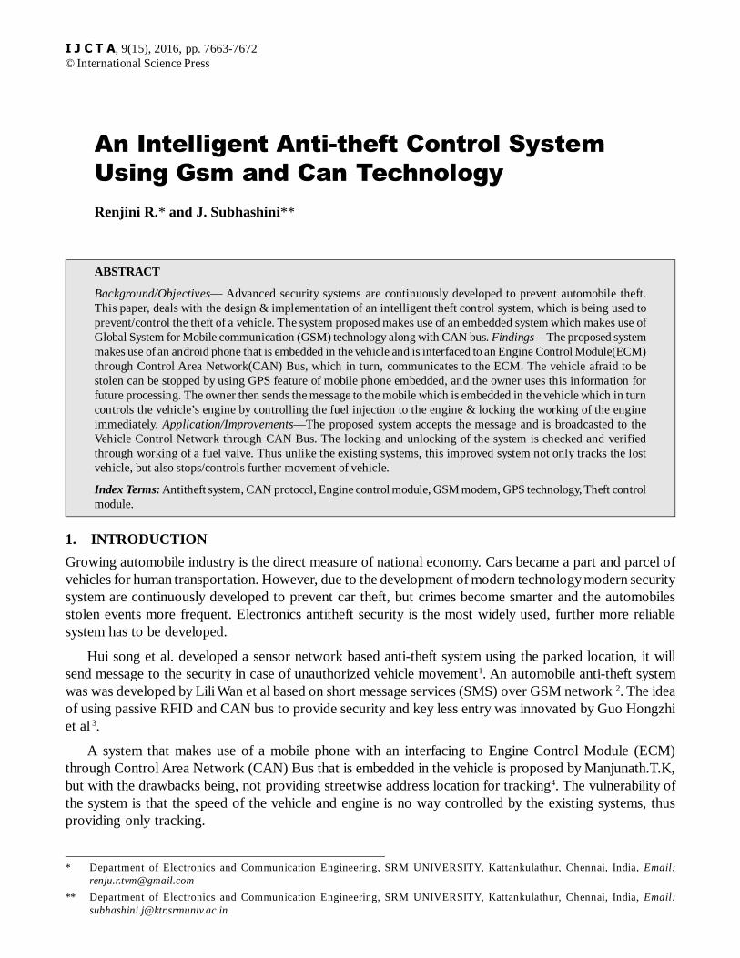
An Intelligent Anti-theft Control SystemUsing Gsm and Can TechnologyRenjini R.* and J. Subhashini**
ABSTRACT
Background/Objectives— Advanced security systems are continuously developed to prevent automobile theft.This paper, deals with the design & implementation of an intelligent theft control system, which is being used toprevent/control the theft of a vehicle. The system proposed makes use of an embedded system which makes use ofGlobal System for Mobile communication (GSM) technology along with CAN bus. Findings—The proposed systemmakes use of an android phone that is embedded in the vehicle and is interfaced to an Engine Control Module(ECM)through Control Area Network(CAN) Bus, which in turn, communicates to the ECM. The vehicle afraid to bestolen can be stopped by using GPS feature of mobile phone embedded, and the owner uses this information forfuture processing. The owner then sends the message to the mobile which is embedded in the vehicle which in turncontrols the vehicle’s engine by controlling the fuel injection to the engine & locking the working of the engineimmediately. Application/Improvements—The proposed system accepts the message and is broadcasted to theVehicle Control Network through CAN Bus. The locking and unlocking of the system is checked and verifiedthrough working of a fuel valve. Thus unlike the existing systems, this improved system not only tracks the lostvehicle, but also stops/controls further movement of vehicle.
Index Terms: Antitheft system, CAN protocol, Engine control module, GSM modem, GPS technology, Theft controlmodule.
1. INTRODUCTION
Growing automobile industry is the direct measure of national economy. Cars became a part and parcel ofvehicles for human transportation. However, due to the development of modern technology modern securitysystem are continuously developed to prevent car theft, but crimes become smarter and the automobilesstolen events more frequent. Electronics antitheft security is the most widely used, further more reliablesystem has to be developed.
Hui song et al. developed a sensor network based anti-theft system using the parked location, it willsend message to the security in case of unauthorized vehicle movement1. An automobile anti-theft systemwas was developed by Lili Wan et al based on short message services (SMS) over GSM network 2. The ideaof using passive RFID and CAN bus to provide security and key less entry was innovated by Guo Hongzhiet al 3.
A system that makes use of a mobile phone with an interfacing to Engine Control Module (ECM)through Control Area Network (CAN) Bus that is embedded in the vehicle is proposed by Manjunath.T.K,but with the drawbacks being, not providing streetwise address location for tracking4. The vulnerability ofthe system is that the speed of the vehicle and engine is no way controlled by the existing systems, thusproviding only tracking.
* Department of Electronics and Communication Engineering, SRM UNIVERSITY, Kattankulathur, Chennai, India, Email:[email protected]
** Department of Electronics and Communication Engineering, SRM UNIVERSITY, Kattankulathur, Chennai, India, Email:[email protected]
I J C T A, 9(15), 2016, pp. 7663-7672© International Science Press
7664 Renjini R. and J. Subhashini
Ambade Shruti Dinkar designed the system which assumes very little processing and communicationrequirements of the sensor and pointing out current location of vehicle using GSM/GPS technology5. HuaqunGuo, Jun Jie Ang and Yongdong presents the details of building both hardware and software that interfaceand directly communicate with CAN network embedded in the automobile. A reliable route for messages isobtained by the extracted CAN messages from automobiles in order to reach its destination 6. Thus, most ofthe works referred reduce the system just to a vehicle tracking system since the engine controlling part hasbeen omitted.
2. DESIGN OF PROPOSED EMBEDDED SYSTEM
Anti-theft vehicular systems, available commercially are found to be very expensive. This paper act towardsthe prevention/control of theft of vehicle by designing a Theft Control System for an automobile. Theproposed system, installed in the vehicle can be easily controlled by the owner of the vehicle from a remoteplace by sending a message from his/her mobile to the vehicle engine by interfacing with CAN bus andGSM modem.7
The vehicle owner uses the information from the GPS satellites, once the vehicle is afraid to bestolen, whereby from a remote place, a message is sent to the GSM modem8 which is interfaced with theECM that is installed in the vehicle. By reading the signals received from the mobile, the engine iscorrespondingly locked/unlocked automatically and speed of the vehicle is reduced/increased. That is,to stop the vehicle, owner sends a message to the control system placed in vehicle and an ECUautomatically stops the fuel flow into the vehicle by sending message through CAN Bus thus reducingengine speed to zero. Again it resumes to normal operation only after owner enters a secured passwordthrough message.
The proposed embedded system uses the main idea of introducing mobile technologies into it. The unitproposed is a cost effective one.
2.1. Existing System
In all the existing systems, we can analyze that vehicle tracking integrates the GPS tracking system9 withexisting vehicle alarm or provide alarm features when someone is tampering with vehicle. Before thevehicle is driven away, security threat is detected and the vehicle is able to be tracked over the internetwhich is done by utilizing Global Positioning Satellites. Through which, data such as Global Position,including latitude and longitude are transmitted over the Cellular network10.This information transmittedfrom the tracking device is stored in your private confidential account or sent over the wireless network.The data is cross referred on a street level map for viewing.11
2.2. Drawbacks of existing system
The crucial disadvantage of the existing system is that the system does not provide street wise address andspeed of the vehicle and engine is no way controlled by the existing systems, thus exposing the vulnerabilityof a system that provides only tracking.12
2.3. Theft Control Unit and Engine Control Unit
The proposed system, has two modules, the theft control and the engine control modules, the theft controlmodule retrieves the geographical location of the vehicle, and correspondingly activates the engine controlunit to control the fuel flow to the engine system. Thus, the proposed theft control system not only retrievesa geographical address but also provides a technique to control the further movement of the vehicle, bycontrolling the speed of the vehicle by locking/unlocking.
An Intelligent Anti-theft Control System Using Gsm and Can Technology 7665
2.4. Proposed Block Diagram
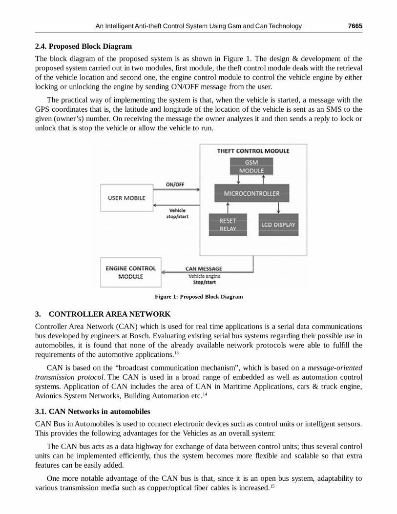
The block diagram of the proposed system is as shown in Figure 1. The design & development of theproposed system carried out in two modules, first module, the theft control module deals with the retrievalof the vehicle location and second one, the engine control module to control the vehicle engine by eitherlocking or unlocking the engine by sending ON/OFF message from the user.
The practical way of implementing the system is that, when the vehicle is started, a message with theGPS coordinates that is, the latitude and longitude of the location of the vehicle is sent as an SMS to thegiven (owner’s) number. On receiving the message the owner analyzes it and then sends a reply to lock orunlock that is stop the vehicle or allow the vehicle to run.
Figure 1: Proposed Block Diagram
3. CONTROLLER AREA NETWORK
Controller Area Network (CAN) which is used for real time applications is a serial data communicationsbus developed by engineers at Bosch. Evaluating existing serial bus systems regarding their possible use inautomobiles, it is found that none of the already available network protocols were able to fulfill therequirements of the automotive applications.13
CAN is based on the “broadcast communication mechanism”, which is based on a message-orientedtransmission protocol. The CAN is used in a broad range of embedded as well as automation controlsystems. Application of CAN includes the area of CAN in Maritime Applications, cars & truck engine,Avionics System Networks, Building Automation etc.14
3.1. CAN Networks in automobiles
CAN Bus in Automobiles is used to connect electronic devices such as control units or intelligent sensors.This provides the following advantages for the Vehicles as an overall system:
The CAN bus acts as a data highway for exchange of data between control units; thus several controlunits can be implemented efficiently, thus the system becomes more flexible and scalable so that extrafeatures can be easily added.
One more notable advantage of the CAN bus is that, since it is an open bus system, adaptability tovarious transmission media such as copper/optical fiber cables is increased.15
7666 Renjini R. and J. Subhashini
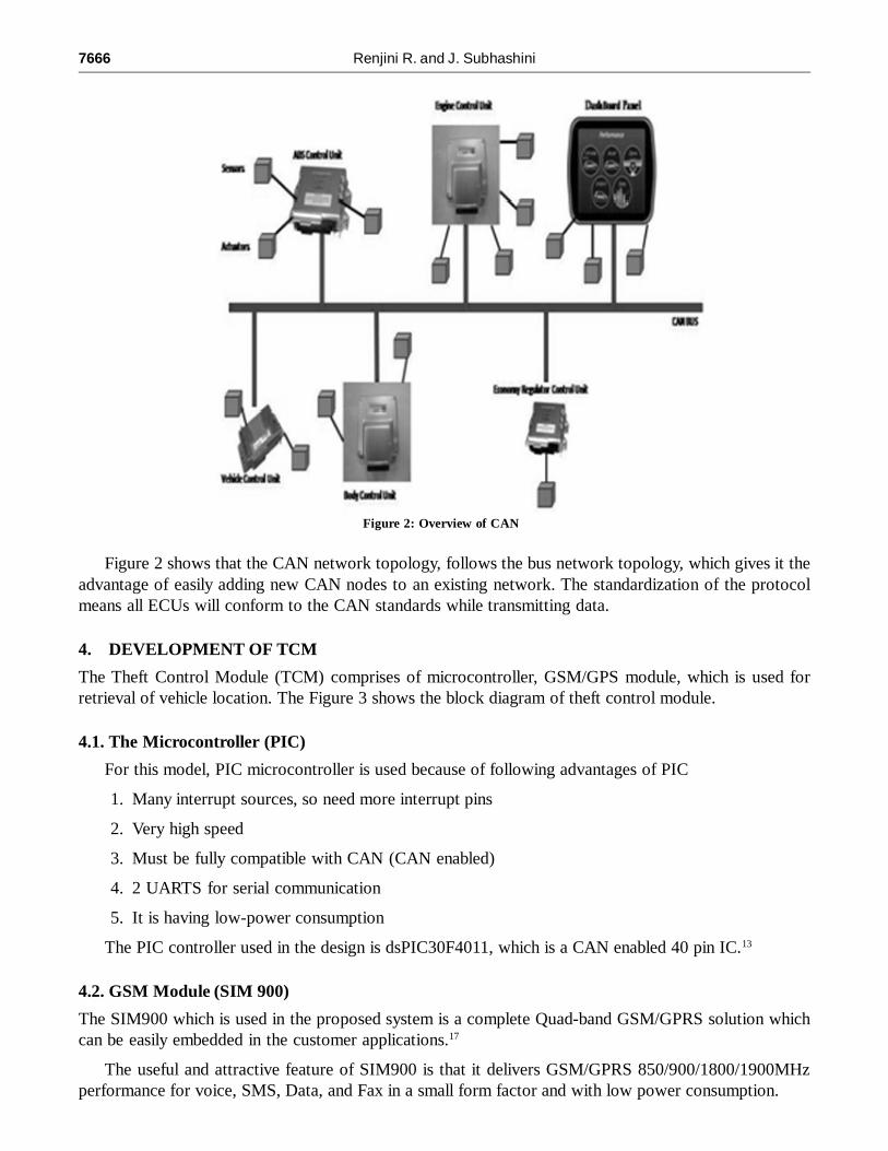
Figure 2 shows that the CAN network topology, follows the bus network topology, which gives it theadvantage of easily adding new CAN nodes to an existing network. The standardization of the protocolmeans all ECUs will conform to the CAN standards while transmitting data.
4. DEVELOPMENT OF TCM
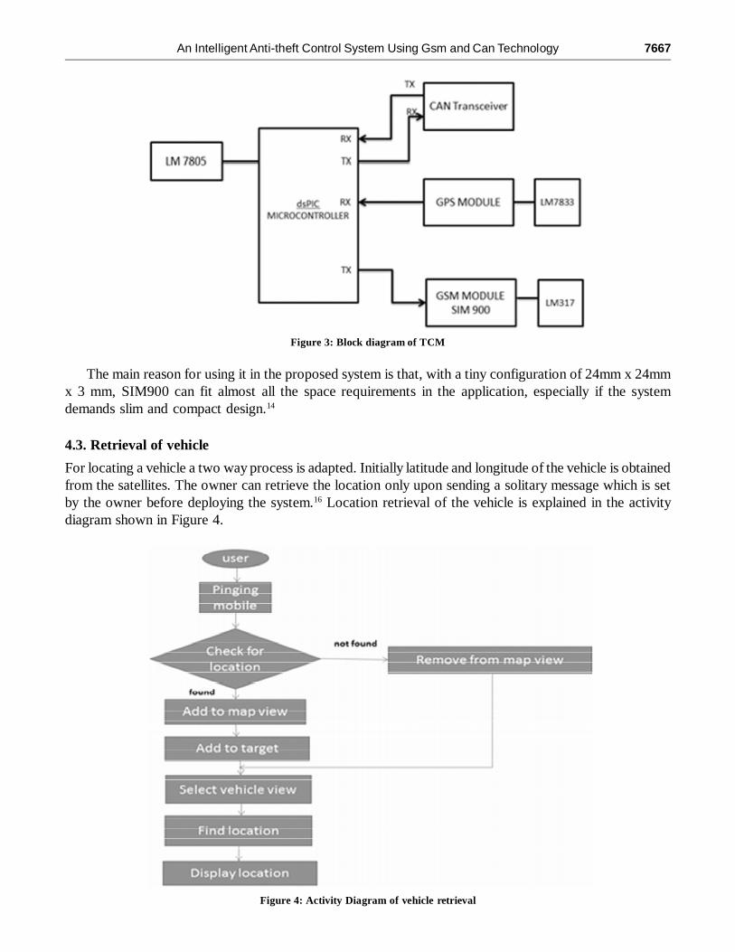
The Theft Control Module (TCM) comprises of microcontroller, GSM/GPS module, which is used forretrieval of vehicle location. The Figure 3 shows the block diagram of theft control module.
4.1. The Microcontroller (PIC)
For this model, PIC microcontroller is used because of following advantages of PIC
1. Many interrupt sources, so need more interrupt pins
2. Very high speed
3. Must be fully compatible with CAN (CAN enabled)
4. 2 UARTS for serial communication
5. It is having low-power consumption
The PIC controller used in the design is dsPIC30F4011, which is a CAN enabled 40 pin IC.13
4.2. GSM Module (SIM 900)
The SIM900 which is used in the proposed system is a complete Quad-band GSM/GPRS solution whichcan be easily embedded in the customer applications.17
The useful and attractive feature of SIM900 is that it delivers GSM/GPRS 850/900/1800/1900MHzperformance for voice, SMS, Data, and Fax in a small form factor and with low power consumption.
Figure 2: Overview of CAN
An Intelligent Anti-theft Control System Using Gsm and Can Technology 7667
The main reason for using it in the proposed system is that, with a tiny configuration of 24mm x 24mmx 3 mm, SIM900 can fit almost all the space requirements in the application, especially if the systemdemands slim and compact design.14
4.3. Retrieval of vehicle
For locating a vehicle a two way process is adapted. Initially latitude and longitude of the vehicle is obtainedfrom the satellites. The owner can retrieve the location only upon sending a solitary message which is setby the owner before deploying the system.16 Location retrieval of the vehicle is explained in the activitydiagram shown in Figure 4.
Figure 3: Block diagram of TCM
Figure 4: Activity Diagram of vehicle retrieval
7668 Renjini R. and J. Subhashini
5. DEVELOPMENT OF ECM
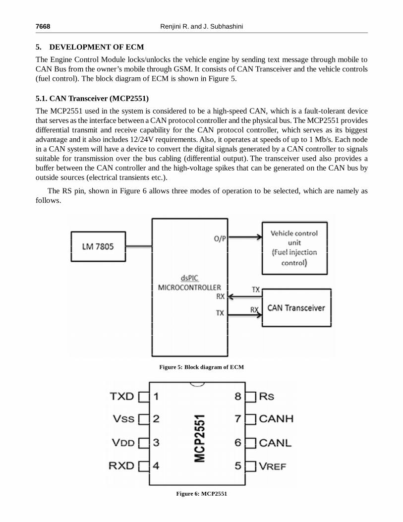
The Engine Control Module locks/unlocks the vehicle engine by sending text message through mobile toCAN Bus from the owner’s mobile through GSM. It consists of CAN Transceiver and the vehicle controls(fuel control). The block diagram of ECM is shown in Figure 5.
5.1. CAN Transceiver (MCP2551)
The MCP2551 used in the system is considered to be a high-speed CAN, which is a fault-tolerant devicethat serves as the interface between a CAN protocol controller and the physical bus. The MCP2551 providesdifferential transmit and receive capability for the CAN protocol controller, which serves as its biggestadvantage and it also includes 12/24V requirements. Also, it operates at speeds of up to 1 Mb/s. Each nodein a CAN system will have a device to convert the digital signals generated by a CAN controller to signalssuitable for transmission over the bus cabling (differential output). The transceiver used also provides abuffer between the CAN controller and the high-voltage spikes that can be generated on the CAN bus byoutside sources (electrical transients etc.).
The RS pin, shown in Figure 6 allows three modes of operation to be selected, which are namely asfollows.
Figure 6: MCP2551
Figure 5: Block diagram of ECM
An Intelligent Anti-theft Control System Using Gsm and Can Technology 7669
• High-Speed
• Slope-Control
• Standby
The first one, High-speed mode is selected by connecting the RS pin to VSS. Here, fast output rise and falltimes are shown by the transmitter output drivers to support high-speed CAN bus rates in this mode. Thesecond one, Slope-control mode is used for further reducing EMI by limiting the rise and fall times of CANHand CANL. And by connecting an external resistor (REXT) between RS and VOL (usually ground) the slopeor slew rate can be controlled. A certain slew rate is achieved by applying a respective resistance since thecurrent is primarily determined by the slope-control resistance value REXT. Thirdly, by applying a high-levelto RS, the device may be placed in standby or SLEEP mode and here the transmitter is switched off and thereceiver operates at a lower current thus saving power in the sleep mode. The receive pin on the controller sideis still functional but will operate at a slower rate. Monitoring the receiving pin for CAN bus activity andplacing the transceiver into normal operation via the RS pin is done by attached microcontroller. Hence for itsversatility and operation in different power saving modes, the proposed system uses this transceiver.
5.2. Vehicle control unit
The locking/unlocking of the vehicle engine is done in the vehicle control unit. Output of the controller isconnected to this unit; the fuel injection is controlled and hence the speed of the vehicle. For ease ofdemonstration, this unit is replaced by dc motor to depict the speed control.
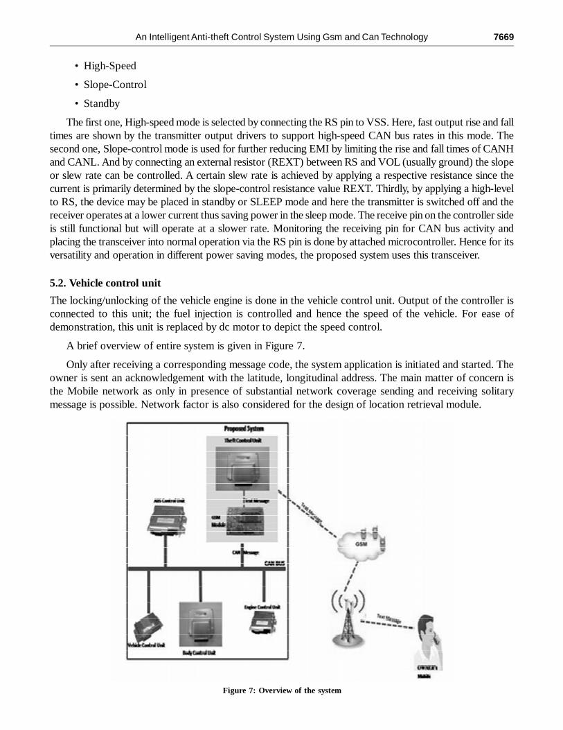
A brief overview of entire system is given in Figure 7.
Only after receiving a corresponding message code, the system application is initiated and started. Theowner is sent an acknowledgement with the latitude, longitudinal address. The main matter of concern isthe Mobile network as only in presence of substantial network coverage sending and receiving solitarymessage is possible. Network factor is also considered for the design of location retrieval module.
Figure 7: Overview of the system
7670 Renjini R. and J. Subhashini
After receiving the message and verifying its authentication, the micro controller installed on the vehicleacts upon the relay to lock or unlock the engine and a SIM card on GSM module in the vehicle wouldreceive the message and would forward it to the micro controller.
6. EXPERIMENTAL RESULTS
The project is at the final stage of implementation. After carrying out experimentation, favorable results areobtained by using the following hardware components.
The components include Android Based Phone, PIC Controller, CAN Transceiver, GSM/GPS Module,and fuel control valve.
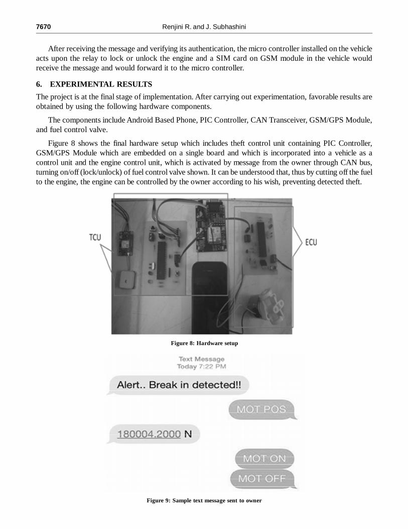
Figure 8 shows the final hardware setup which includes theft control unit containing PIC Controller,GSM/GPS Module which are embedded on a single board and which is incorporated into a vehicle as acontrol unit and the engine control unit, which is activated by message from the owner through CAN bus,turning on/off (lock/unlock) of fuel control valve shown. It can be understood that, thus by cutting off the fuelto the engine, the engine can be controlled by the owner according to his wish, preventing detected theft.
Figure 8: Hardware setup
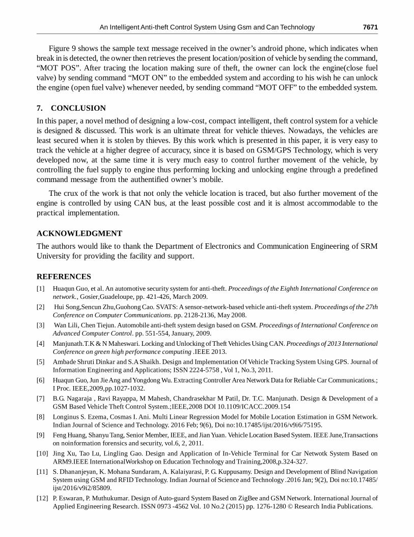
Figure 9: Sample text message sent to owner
An Intelligent Anti-theft Control System Using Gsm and Can Technology 7671
Figure 9 shows the sample text message received in the owner’s android phone, which indicates whenbreak in is detected, the owner then retrieves the present location/position of vehicle by sending the command,“MOT POS”. After tracing the location making sure of theft, the owner can lock the engine(close fuelvalve) by sending command “MOT ON” to the embedded system and according to his wish he can unlockthe engine (open fuel valve) whenever needed, by sending command “MOT OFF” to the embedded system.
7. CONCLUSION
In this paper, a novel method of designing a low-cost, compact intelligent, theft control system for a vehicleis designed & discussed. This work is an ultimate threat for vehicle thieves. Nowadays, the vehicles areleast secured when it is stolen by thieves. By this work which is presented in this paper, it is very easy totrack the vehicle at a higher degree of accuracy, since it is based on GSM/GPS Technology, which is verydeveloped now, at the same time it is very much easy to control further movement of the vehicle, bycontrolling the fuel supply to engine thus performing locking and unlocking engine through a predefinedcommand message from the authentified owner’s mobile.
The crux of the work is that not only the vehicle location is traced, but also further movement of theengine is controlled by using CAN bus, at the least possible cost and it is almost accommodable to thepractical implementation.
ACKNOWLEDGMENT
The authors would like to thank the Department of Electronics and Communication Engineering of SRMUniversity for providing the facility and support.
REFERENCES[1] Huaqun Guo, et al. An automotive security system for anti-theft. Proceedings of the Eighth International Conference on
network., Gosier,Guadeloupe, pp. 421-426, March 2009.
[2] Hui Song,Sencun Zhu,Guohong Cao. SVATS: A sensor-network-based vehicle anti-theft system. Proceedings of the 27thConference on Computer Communications. pp. 2128-2136, May 2008.
[3] Wan Lili, Chen Tiejun. Automobile anti-theft system design based on GSM. Proceedings of International Conference onAdvanced Computer Control. pp. 551-554, January, 2009.
[4] Manjunath.T.K & N Maheswari. Locking and Unlocking of Theft Vehicles Using CAN. Proceedings of 2013 InternationalConference on green high performance computing .IEEE 2013.
[5] Ambade Shruti Dinkar and S.A Shaikh. Design and Implementation Of Vehicle Tracking System Using GPS. Journal ofInformation Engineering and Applications; ISSN 2224-5758 , Vol 1, No.3, 2011.
[6] Huaqun Guo, Jun Jie Ang and Yongdong Wu. Extracting Controller Area Network Data for Reliable Car Communications.;I Proc. IEEE,2009,pp.1027-1032.
[7] B.G. Nagaraja , Ravi Rayappa, M Mahesh, Chandrasekhar M Patil, Dr. T.C. Manjunath. Design & Development of aGSM Based Vehicle Theft Control System.;IEEE,2008 DOI 10.1109/ICACC.2009.154
[8] Longinus S. Ezema, Cosmas I. Ani. Multi Linear Regression Model for Mobile Location Estimation in GSM Network.Indian Journal of Science and Technology. 2016 Feb; 9(6), Doi no:10.17485/ijst/2016/v9i6/75195.
[9] Feng Huang, Shanyu Tang, Senior Member, IEEE, and Jian Yuan. Vehicle Location Based System. IEEE June,Transactionson noinformation forensics and security, vol.6, 2, 2011.
[10] Jing Xu, Tao Lu, Lingling Gao. Design and Application of In-Vehicle Terminal for Car Netwotk System Based onARM9.IEEE InternationalWorkshop on Education Technology and Training,2008,p.324-327.
[11] S. Dhananjeyan, K. Mohana Sundaram, A. Kalaiyarasi, P. G. Kuppusamy. Design and Development of Blind NavigationSystem using GSM and RFID Technology. Indian Journal of Science and Technology .2016 Jan; 9(2), Doi no:10.17485/ijst/2016/v9i2/85809.
[12] P. Eswaran, P. Muthukumar. Design of Auto-guard System Based on ZigBee and GSM Network. International Journal ofApplied Engineering Research. ISSN 0973 -4562 Vol. 10 No.2 (2015) pp. 1276-1280 © Research India Publications.
7672 Renjini R. and J. Subhashini
[13] CAN in Automation (CiA),Controller Area Network (CAN) . Avaliable: http://www.can-cia.org/. Date accessed: 06/11/2015.
[14] Ashwini S. Shinde, Prof. Vidhyadhar B. Dharmadhikari. Controller Area Network for Vehicle Automation. InternationalJournal of Emerging Technology and Advanced Engineering, ISSN 2250-2459. Volume 2, Issue 2, February 2012.
[15] Vikash Kumar Singh, Kumari Archana. Implementation Of ‘CAN’ Protocol In Automobiles Using Advance EmbeddedSystem. International Journal of Engineering Trends and Technology (IJETT) – Volume 4 Issue 10- Oct 2013.
[16] Muhammad Ridhwan Ahmad Fuad and Micheal Drieberg .Remote Vehicle Tracking System using GSM Modem andGoogle Map. Conference on Sustainable Utilization and Development in Engineering and Technology, IEEE 2013.
[17] Bavya R, Mohanmurali. Next generation auto theft prevention and tracking system for land vehicles. ICICES2014 , IEEE2014.
[18] Sahadev Roy, Rajesh Saha, Chandan Tilak Bhunia. A Secure Authentication Infrastructure for IoT Enabled Smart MobileDevices – An Initial Prototype. Indian Journal of Science and Technology.2016 Feb; 9(9), Doi no: 10.17485/ijst/2016/v9i9/73250.
[19] D. Jinil Persis, T. Paul Robert. Ant Based Multi-objective Routing Optimization in Mobile AD-HOC Network. IndianJournal of Science and Technology.2015 May; 8(9), Doi no: 0.17485/ijst/2015/v8i9/59369.
[20] Md. Amir Khusru Akhtar, G. Sahoo. Behavior Based High Performance Protocol for MANET. Indian Journal of Scienceand Technology. 2013 Oct; 6(10), Doi no:10.17485/ijst/2013/v6i10/38794.


![Detection of GSM Based Accident Location, Vehicle Theft ... · Mohammad Salah Uddin et al., [12] described smart anti-theft vehicle tracking system based IOT. The GPS, GSM/GPRS and](https://img.pdfslide.us/doc/110x75/5e1c4f73f257db723e24178e/detection-of-gsm-based-accident-location-vehicle-theft-mohammad-salah-uddin.jpg)