Embed Size (px)
Citation preview
H2S Splitting Hot PaperDOI: 10.1002/anie.201400571
An Integrated Photoelectrochemical–Chemical Loop for Solar-DrivenOverall Splitting of Hydrogen Sulfide**Xu Zong, Jingfeng Han, Brian Seger, Hongjun Chen, Gaoqing (Max) Lu, Can Li,* andLianzhou Wang*
Abstract: Abundant and toxic hydrogen sulfide (H2S) fromindustry and nature has been traditionally considered a liability.However, it represents a potential resource if valuable H2 andelemental sulfur can be simultaneously extracted through a H2Ssplitting reaction. Herein a photochemical-chemical looplinked by redox couples such as Fe2+/Fe3+ and I�/I3
� forphotoelectrochemical H2 production and H2S chemicalabsorption redox reactions are reported. Using functionalizedSi as photoelectrodes, H2S was successfully split into elementalsulfur and H2 with high stability and selectivity under simulatedsolar light. This new conceptual design will not only providea possible route for using solar energy to convert H2S intovaluable resources, but also sheds light on some challengingphotochemical reactions such as CH4 activation and CO2
reduction.
Hydrogen sulfide (H2S) is an abundant chemical producedby industry and occurring in nature. Although H2S representspotential resources of two elements which individually havesignificant economic value, its potential has been hardlyrealized by community because of its extremely toxic andirritating nature and existing treating techniques. However,there is an increasing recognition that H2S could becomea potentially valuable chemical if a process that can simulta-neously extract H2 and elemental sulfur (S) from H2S wasdeveloped.[1] At present, H2S is primarily treated with Clausprocess wherein it is partially oxidized to yield elemental Sand water.[2] Although S can be extracted from H2S with thisapproach, one of the disadvantages is the loss of H2 in H2Sduring the conversion. Therefore, it is highly desirable todevelop a sustainable and cost-effective process to simulta-neously recover H2 and S from H2S.
The H2S splitting reaction (DG0 = 33 kJmol�1) is thermo-dynamically less stringent compared with the H2O splittingreaction (DG0 = 273 kJ mol�1).[3] To date, differentapproaches including thermal,[4] thermochemical,[5] electro-chemical,[6] photochemical,[7] and plasmochemical[8] decom-position methods have been investigated for H2S splitting.Among these approaches, photochemical splitting of H2S isattractive because of its potential of using abundant solarenergy.[9] The prevalent reaction scheme for photochemicalH2S splitting is shown in Scheme 1 a. In the first step, H2S ischemically absorbed in alkali solution (such as NaOHsolution) to generate S2�. In the second step, S2� is oxidizedby photogenerated holes to polysulfide and protons arereduced to H2. Although H2 can be extracted from H2S usingthis approach, it is difficult to recover S because of the highlybasic nature of the absorption solution.[10] Moreover, thegeneration of polysulfide by-products and the shielding oflight by the polysulfide ions inevitably introduce new environ-mental and technical challenges, which makes this methodless appealing. So far, the development of a sustainable andeconomically viable photochemical approach that can splitH2S to produce H2 and S simultaneously still remainsa challenging task.
Herein we report an innovative approach that cansimultaneously extract H2 and S from toxic H2S by usingsolar energy. Through the integration of photoelectrochem-ical and chemical reactions linked by I�/I3
� or Fe2+/Fe3+ redoxcouples, H2S can be successfully split into S and H2 with highstability and selectivity. To our knowledge, this is the firstreported photoelectrochemical process for overall splitting ofH2S without the necessity of post-treating sulfur-basedaqueous solution. This conceptually provides an alternative
[*] Dr. X. Zong, Dr. H. J. Chen, Prof. G. Q. (Max) Lu, Prof. L. Z. WangNanomaterials Centre, School of Chemical Engineering andAustralian Institute for Bioengineering and NanotechnologyThe University of QueenslandQLD 4072 (Australia)E-mail: [email protected]
J. F. Han, Prof. Dr. C. LiState Key Laboratory of CatalysisDalian Institute of Chemical PhysicsChinese Academy of Sciences and Dalian Laboratory for CleanEnergyDalian 116023 (China)E-mail: [email protected]: http://www.canli.dicp.ac.cn
J. F. HanGraduate University of Chinese Academy of SciencesBeijing 100049 (China)
Dr. B. SegerDepartment of Physics, CINF, Technical University of Denmark2800 Kongens Lyngby (Denmark)
[**] This project was supported by the Australian Research Council(through its DP and FT programs) and Queensland State Govern-ment Smart State program (NIRAP). This work was performed inpart at the Qld node of the Australian National Fabrication Facility.We gratefully acknowledge the Danish Ministry of Science forfunding the Catalysis for Sustainable Energy (CASE) initiative andthe Danish National Research Foundation for founding The Centerfor Individual Nanoparticle Functionality. We also thank ThomasPedersen (DTU) for providing p-n junction Si wafers.
Supporting information for this article is available on the WWWunder http://dx.doi.org/10.1002/anie.201400571.
AngewandteChemie
1Angew. Chem. Int. Ed. 2014, 53, 1 – 6 � 2014 Wiley-VCH Verlag GmbH & Co. KGaA, Weinheim
These are not the final page numbers! � �
approach for converting abundant and toxic H2S to valuablechemicals using solar energy.
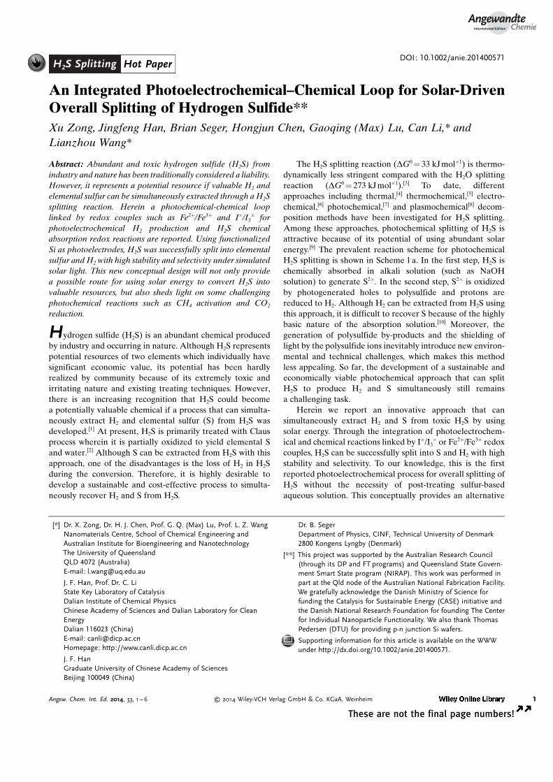
Our process of converting H2S to H2 and S consists of twointegrated reactions as schematically shown in Scheme 1band Scheme S1 in the Supporting Information. The firstreaction is a simple chemical reaction (reaction 1) that canefficiently trap and selectively convert H2S to S and protonsby the oxidation state of redox couples(I�/I3
� or Fe2+/Fe3+).The second reaction is a photoelectrochemical reaction(reaction 2) that can reduce protons to generate H2. In themeantime, the reduction state of the redox couples is restoredto the initial oxidation state by the photogenerated holes.Thus with the link of the redox couples, the net reaction is theoverall splitting of H2S to produce both H2 and S using solarenergy.
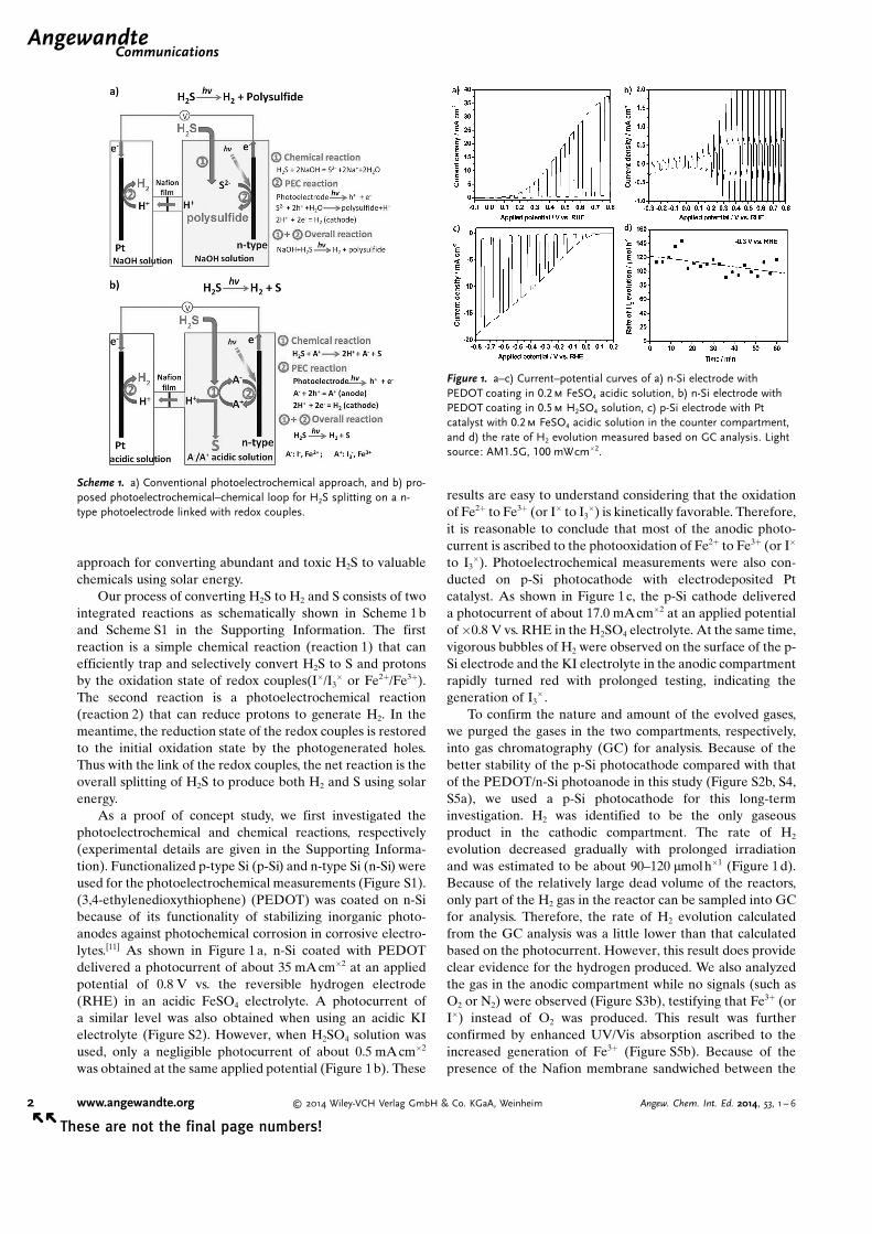
As a proof of concept study, we first investigated thephotoelectrochemical and chemical reactions, respectively(experimental details are given in the Supporting Informa-tion). Functionalized p-type Si (p-Si) and n-type Si (n-Si) wereused for the photoelectrochemical measurements (Figure S1).(3,4-ethylenedioxythiophene) (PEDOT) was coated on n-Sibecause of its functionality of stabilizing inorganic photo-anodes against photochemical corrosion in corrosive electro-lytes.[11] As shown in Figure 1a, n-Si coated with PEDOTdelivered a photocurrent of about 35 mA cm�2 at an appliedpotential of 0.8 V vs. the reversible hydrogen electrode(RHE) in an acidic FeSO4 electrolyte. A photocurrent ofa similar level was also obtained when using an acidic KIelectrolyte (Figure S2). However, when H2SO4 solution wasused, only a negligible photocurrent of about 0.5 mAcm�2
was obtained at the same applied potential (Figure 1b). These
results are easy to understand considering that the oxidationof Fe2+ to Fe3+ (or I� to I3
�) is kinetically favorable. Therefore,it is reasonable to conclude that most of the anodic photo-current is ascribed to the photooxidation of Fe2+ to Fe3+ (or I�
to I3�). Photoelectrochemical measurements were also con-
ducted on p-Si photocathode with electrodeposited Ptcatalyst. As shown in Figure 1c, the p-Si cathode delivereda photocurrent of about 17.0 mAcm�2 at an applied potentialof�0.8 V vs. RHE in the H2SO4 electrolyte. At the same time,vigorous bubbles of H2 were observed on the surface of the p-Si electrode and the KI electrolyte in the anodic compartmentrapidly turned red with prolonged testing, indicating thegeneration of I3
� .To confirm the nature and amount of the evolved gases,
we purged the gases in the two compartments, respectively,into gas chromatography (GC) for analysis. Because of thebetter stability of the p-Si photocathode compared with thatof the PEDOT/n-Si photoanode in this study (Figure S2b, S4,S5a), we used a p-Si photocathode for this long-terminvestigation. H2 was identified to be the only gaseousproduct in the cathodic compartment. The rate of H2
evolution decreased gradually with prolonged irradiationand was estimated to be about 90–120 mmolh�1 (Figure 1 d).Because of the relatively large dead volume of the reactors,only part of the H2 gas in the reactor can be sampled into GCfor analysis. Therefore, the rate of H2 evolution calculatedfrom the GC analysis was a little lower than that calculatedbased on the photocurrent. However, this result does provideclear evidence for the hydrogen produced. We also analyzedthe gas in the anodic compartment while no signals (such asO2 or N2) were observed (Figure S3b), testifying that Fe3+ (orI�) instead of O2 was produced. This result was furtherconfirmed by enhanced UV/Vis absorption ascribed to theincreased generation of Fe3+ (Figure S5b). Because of thepresence of the Nafion membrane sandwiched between the
Scheme 1. a) Conventional photoelectrochemical approach, and b) pro-posed photoelectrochemical–chemical loop for H2S splitting on a n-type photoelectrode linked with redox couples.
Figure 1. a–c) Current–potential curves of a) n-Si electrode withPEDOT coating in 0.2m FeSO4 acidic solution, b) n-Si electrode withPEDOT coating in 0.5m H2SO4 solution, c) p-Si electrode with Ptcatalyst with 0.2m FeSO4 acidic solution in the counter compartment,and d) the rate of H2 evolution measured based on GC analysis. Lightsource: AM1.5G, 100 mWcm�2.
.AngewandteCommunications
2 www.angewandte.org � 2014 Wiley-VCH Verlag GmbH & Co. KGaA, Weinheim Angew. Chem. Int. Ed. 2014, 53, 1 – 6� �
These are not the final page numbers!
two compartments, the production of Fe3+ (or I3�) is
anticipated to be confined in the compartment where photo-oxidation reaction takes place (Figure 2a). This design willprohibit the backward reaction of Fe3+ to Fe2+ (or I3
� to I�) onthe photocathode and ensure that most of the Fe3+ or I3
�
could be used for the subsequent chemical reactions.After confirming that H2 can be produced with the
simultaneous generation of Fe3+ or I3� , we then proceeded
with the second step of our design by slowly bubbling H2S intothe electrolytes containing Fe3+ or I3
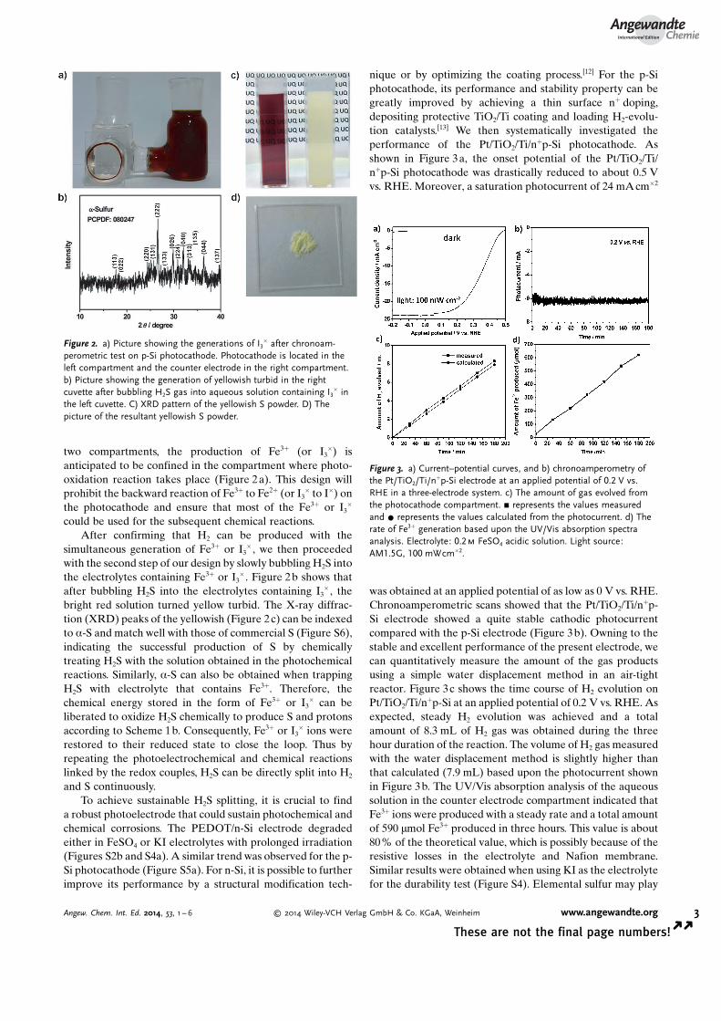
� . Figure 2b shows thatafter bubbling H2S into the electrolytes containing I3
� , thebright red solution turned yellow turbid. The X-ray diffrac-tion (XRD) peaks of the yellowish (Figure 2 c) can be indexedto a-S and match well with those of commercial S (Figure S6),indicating the successful production of S by chemicallytreating H2S with the solution obtained in the photochemicalreactions. Similarly, a-S can also be obtained when trappingH2S with electrolyte that contains Fe3+. Therefore, thechemical energy stored in the form of Fe3+ or I3
� can beliberated to oxidize H2S chemically to produce S and protonsaccording to Scheme 1b. Consequently, Fe3+ or I3
� ions wererestored to their reduced state to close the loop. Thus byrepeating the photoelectrochemical and chemical reactionslinked by the redox couples, H2S can be directly split into H2
and S continuously.To achieve sustainable H2S splitting, it is crucial to find
a robust photoelectrode that could sustain photochemical andchemical corrosions. The PEDOT/n-Si electrode degradedeither in FeSO4 or KI electrolytes with prolonged irradiation(Figures S2b and S4a). A similar trend was observed for the p-Si photocathode (Figure S5a). For n-Si, it is possible to furtherimprove its performance by a structural modification tech-
nique or by optimizing the coating process.[12] For the p-Siphotocathode, its performance and stability property can begreatly improved by achieving a thin surface n+ doping,depositing protective TiO2/Ti coating and loading H2-evolu-tion catalysts.[13] We then systematically investigated theperformance of the Pt/TiO2/Ti/n+p-Si photocathode. Asshown in Figure 3a, the onset potential of the Pt/TiO2/Ti/n+p-Si photocathode was drastically reduced to about 0.5 Vvs. RHE. Moreover, a saturation photocurrent of 24 mAcm�2
was obtained at an applied potential of as low as 0 V vs. RHE.Chronoamperometric scans showed that the Pt/TiO2/Ti/n+p-Si electrode showed a quite stable cathodic photocurrentcompared with the p-Si electrode (Figure 3b). Owning to thestable and excellent performance of the present electrode, wecan quantitatively measure the amount of the gas productsusing a simple water displacement method in an air-tightreactor. Figure 3c shows the time course of H2 evolution onPt/TiO2/Ti/n+p-Si at an applied potential of 0.2 V vs. RHE. Asexpected, steady H2 evolution was achieved and a totalamount of 8.3 mL of H2 gas was obtained during the threehour duration of the reaction. The volume of H2 gas measuredwith the water displacement method is slightly higher thanthat calculated (7.9 mL) based upon the photocurrent shownin Figure 3b. The UV/Vis absorption analysis of the aqueoussolution in the counter electrode compartment indicated thatFe3+ ions were produced with a steady rate and a total amountof 590 mmol Fe3+ produced in three hours. This value is about80% of the theoretical value, which is possibly because of theresistive losses in the electrolyte and Nafion membrane.Similar results were obtained when using KI as the electrolytefor the durability test (Figure S4). Elemental sulfur may play
Figure 2. a) Picture showing the generations of I3� after chronoam-
perometric test on p-Si photocathode. Photocathode is located in theleft compartment and the counter electrode in the right compartment.b) Picture showing the generation of yellowish turbid in the rightcuvette after bubbling H2S gas into aqueous solution containing I3
� inthe left cuvette. C) XRD pattern of the yellowish S powder. D) Thepicture of the resultant yellowish S powder.
Figure 3. a) Current–potential curves, and b) chronoamperometry ofthe Pt/TiO2/Ti/n+p-Si electrode at an applied potential of 0.2 V vs.RHE in a three-electrode system. c) The amount of gas evolved fromthe photocathode compartment. & represents the values measuredand * represents the values calculated from the photocurrent. d) Therate of Fe3+ generation based upon the UV/Vis absorption spectraanalysis. Electrolyte: 0.2m FeSO4 acidic solution. Light source:AM1.5G, 100 mWcm�2.
AngewandteChemie
3Angew. Chem. Int. Ed. 2014, 53, 1 – 6 � 2014 Wiley-VCH Verlag GmbH & Co. KGaA, Weinheim www.angewandte.org
These are not the final page numbers! � �
a role in contributing to the photocurrent observed.[14]
However, as the photoactivity of the sulfur electrode isnormally much smaller than that of the Si electrode, theinfluence should be negligible.
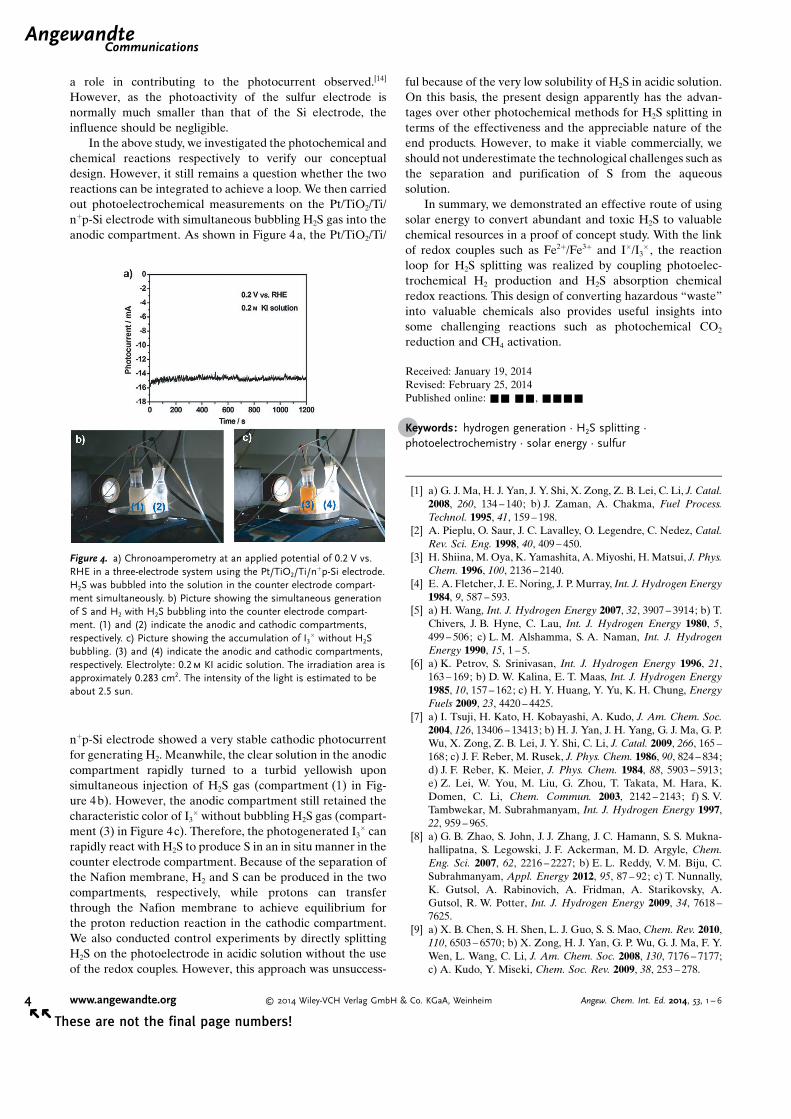
In the above study, we investigated the photochemical andchemical reactions respectively to verify our conceptualdesign. However, it still remains a question whether the tworeactions can be integrated to achieve a loop. We then carriedout photoelectrochemical measurements on the Pt/TiO2/Ti/n+p-Si electrode with simultaneous bubbling H2S gas into theanodic compartment. As shown in Figure 4a, the Pt/TiO2/Ti/
n+p-Si electrode showed a very stable cathodic photocurrentfor generating H2. Meanwhile, the clear solution in the anodiccompartment rapidly turned to a turbid yellowish uponsimultaneous injection of H2S gas (compartment (1) in Fig-ure 4b). However, the anodic compartment still retained thecharacteristic color of I3
� without bubbling H2S gas (compart-ment (3) in Figure 4c). Therefore, the photogenerated I3
� canrapidly react with H2S to produce S in an in situ manner in thecounter electrode compartment. Because of the separation ofthe Nafion membrane, H2 and S can be produced in the twocompartments, respectively, while protons can transferthrough the Nafion membrane to achieve equilibrium forthe proton reduction reaction in the cathodic compartment.We also conducted control experiments by directly splittingH2S on the photoelectrode in acidic solution without the useof the redox couples. However, this approach was unsuccess-
ful because of the very low solubility of H2S in acidic solution.On this basis, the present design apparently has the advan-tages over other photochemical methods for H2S splitting interms of the effectiveness and the appreciable nature of theend products. However, to make it viable commercially, weshould not underestimate the technological challenges such asthe separation and purification of S from the aqueoussolution.
In summary, we demonstrated an effective route of usingsolar energy to convert abundant and toxic H2S to valuablechemical resources in a proof of concept study. With the linkof redox couples such as Fe2+/Fe3+ and I�/I3
� , the reactionloop for H2S splitting was realized by coupling photoelec-trochemical H2 production and H2S absorption chemicalredox reactions. This design of converting hazardous “waste”into valuable chemicals also provides useful insights intosome challenging reactions such as photochemical CO2
reduction and CH4 activation.
Received: January 19, 2014Revised: February 25, 2014Published online: && &&, &&&&
.Keywords: hydrogen generation · H2S splitting ·photoelectrochemistry · solar energy · sulfur
[1] a) G. J. Ma, H. J. Yan, J. Y. Shi, X. Zong, Z. B. Lei, C. Li, J. Catal.2008, 260, 134 – 140; b) J. Zaman, A. Chakma, Fuel Process.Technol. 1995, 41, 159 – 198.
[2] A. Pieplu, O. Saur, J. C. Lavalley, O. Legendre, C. Nedez, Catal.Rev. Sci. Eng. 1998, 40, 409 – 450.
[3] H. Shiina, M. Oya, K. Yamashita, A. Miyoshi, H. Matsui, J. Phys.Chem. 1996, 100, 2136 – 2140.
[4] E. A. Fletcher, J. E. Noring, J. P. Murray, Int. J. Hydrogen Energy1984, 9, 587 – 593.
[5] a) H. Wang, Int. J. Hydrogen Energy 2007, 32, 3907 – 3914; b) T.Chivers, J. B. Hyne, C. Lau, Int. J. Hydrogen Energy 1980, 5,499 – 506; c) L. M. Alshamma, S. A. Naman, Int. J. HydrogenEnergy 1990, 15, 1 – 5.
[6] a) K. Petrov, S. Srinivasan, Int. J. Hydrogen Energy 1996, 21,163 – 169; b) D. W. Kalina, E. T. Maas, Int. J. Hydrogen Energy1985, 10, 157 – 162; c) H. Y. Huang, Y. Yu, K. H. Chung, EnergyFuels 2009, 23, 4420 – 4425.
[7] a) I. Tsuji, H. Kato, H. Kobayashi, A. Kudo, J. Am. Chem. Soc.2004, 126, 13406 – 13413; b) H. J. Yan, J. H. Yang, G. J. Ma, G. P.Wu, X. Zong, Z. B. Lei, J. Y. Shi, C. Li, J. Catal. 2009, 266, 165 –168; c) J. F. Reber, M. Rusek, J. Phys. Chem. 1986, 90, 824 – 834;d) J. F. Reber, K. Meier, J. Phys. Chem. 1984, 88, 5903 – 5913;e) Z. Lei, W. You, M. Liu, G. Zhou, T. Takata, M. Hara, K.Domen, C. Li, Chem. Commun. 2003, 2142 – 2143; f) S. V.Tambwekar, M. Subrahmanyam, Int. J. Hydrogen Energy 1997,22, 959 – 965.
[8] a) G. B. Zhao, S. John, J. J. Zhang, J. C. Hamann, S. S. Mukna-hallipatna, S. Legowski, J. F. Ackerman, M. D. Argyle, Chem.Eng. Sci. 2007, 62, 2216 – 2227; b) E. L. Reddy, V. M. Biju, C.Subrahmanyam, Appl. Energy 2012, 95, 87 – 92; c) T. Nunnally,K. Gutsol, A. Rabinovich, A. Fridman, A. Starikovsky, A.Gutsol, R. W. Potter, Int. J. Hydrogen Energy 2009, 34, 7618 –7625.
[9] a) X. B. Chen, S. H. Shen, L. J. Guo, S. S. Mao, Chem. Rev. 2010,110, 6503 – 6570; b) X. Zong, H. J. Yan, G. P. Wu, G. J. Ma, F. Y.Wen, L. Wang, C. Li, J. Am. Chem. Soc. 2008, 130, 7176 – 7177;c) A. Kudo, Y. Miseki, Chem. Soc. Rev. 2009, 38, 253 – 278.
Figure 4. a) Chronoamperometry at an applied potential of 0.2 V vs.RHE in a three-electrode system using the Pt/TiO2/Ti/n+p-Si electrode.H2S was bubbled into the solution in the counter electrode compart-ment simultaneously. b) Picture showing the simultaneous generationof S and H2 with H2S bubbling into the counter electrode compart-ment. (1) and (2) indicate the anodic and cathodic compartments,respectively. c) Picture showing the accumulation of I3
� without H2Sbubbling. (3) and (4) indicate the anodic and cathodic compartments,respectively. Electrolyte: 0.2m KI acidic solution. The irradiation area isapproximately 0.283 cm2. The intensity of the light is estimated to beabout 2.5 sun.
.AngewandteCommunications
4 www.angewandte.org � 2014 Wiley-VCH Verlag GmbH & Co. KGaA, Weinheim Angew. Chem. Int. Ed. 2014, 53, 1 – 6� �
These are not the final page numbers!

[10] a) P. Dubois, J. P. Lelieur, G. Lepoutre, Inorg. Chem. 1987, 26,1897 – 1902; b) P. Dubois, J. P. Lelieur, G. Lepoutre, Inorg.Chem. 1988, 27, 1883 – 1890.
[11] S. Mubeen, J. Lee, N. Singh, M. Moskovits, E. W. McFarland,Energy Environ. Sci. 2013, 6, 1633 – 1639.
[12] a) T. Yang, H. Wang, X. M. Ou, C. S. Lee, X. H. Zhang, Adv.Mater. 2012, 24, 6199 – 6203; b) K. Q. Peng, S. T. Lee, Adv. Mater.2011, 23, 198 – 215; c) X. J. Li, W. H. Lu, W. L. Dong, Q. Chen, D.Wu, W. Z. Zhou, L. W. Chen, Nanoscale 2013, 5, 5257 – 5261.
[13] a) B. Seger, A. B. Laursen, P. C. K. Vesborg, T. Pedersen, O.Hansen, S. Dahl, I. Chorkendorff, Angew. Chem. 2012, 124,9262 – 9265; Angew. Chem. Int. Ed. 2012, 51, 9128 – 9131; b) B.Seger, T. Pedersen, A. B. Laursen, P. C. K. Vesborg, O. Hansen,I. Chorkendorff, J. Am. Chem. Soc. 2013, 135, 1057 – 1064.
[14] G. Liu, P. Niu, Li. C. Yin, H. M. Cheng, J. Am. Chem. Soc. 2012,134, 9070 – 9073.
AngewandteChemie
5Angew. Chem. Int. Ed. 2014, 53, 1 – 6 � 2014 Wiley-VCH Verlag GmbH & Co. KGaA, Weinheim www.angewandte.org
These are not the final page numbers! � �

Communications
H2S Splitting
X. Zong, J. F. Han, B. Seger, H. J. Chen,G. Q. (Max) Lu, C. Li,*L. Z. Wang* &&&&—&&&&
An Integrated Photoelectrochemical–Chemical Loop for Solar-Driven OverallSplitting of Hydrogen Sulfide
Trash to Treasure: A photochemical–chemical loop for the overall H2S splittingwas developed by integrating photoelec-trochemical H2 production and H2Schemical absorption redox reactions withthe link of a redox couple (Fe2+/Fe3+ or I�/I3�). Using functionalized silicon as pho-
toelectrode, simultaneous extraction ofH2 and elemental sulfur from H2S wassuccessfully achieved (see picture).
.AngewandteCommunications
6 www.angewandte.org � 2014 Wiley-VCH Verlag GmbH & Co. KGaA, Weinheim Angew. Chem. Int. Ed. 2014, 53, 1 – 6� �
These are not the final page numbers!


![$ 7KLV Toward Efficient Solar Water Splitting … · 2018-05-01 · I Synthesis of MoSElectronic2 from Supplementary [Mo3S7(S2CNEt Information2)3]I for Enhancing Photoelectrochemical](https://img.pdfslide.us/doc/110x75/5e6b2e19a44791530a5101d4/-7klv-toward-efficient-solar-water-splitting-2018-05-01-i-synthesis-of-moselectronic2.jpg)