Embed Size (px)
Citation preview
An Integrated Mechanical Intelligence and Control Approach TowardsFlight Control of Aerobat
Eric Sihite, Atefe Darabi, Pravin Dangol, Andrew Lessieur, and Alireza Ramezani1
Abstract— Our goal in this work is to expand the theory andpractice of robot locomotion by addressing critical challengesassociated with the robotic biomimicry of bat aerial locomotion.Bats are known for their pronounced, fast wing articulations,e.g., bats can mobilize as many as forty joints during a singlewingbeat, with some joints reaching to over one thousanddegrees per second in angular speed. Copying bats flight is asignificant ordeal, however, very rewarding. Aerial drones withmorphing bodies similar to bats can be safer, agile and energyefficient owing to their articulated and soft wings. Currentdesign paradigms have failed to copy bat flight because they as-sume only closed-loop feedback roles and ignore computationalroles carried out by morphology. To respond to the urgency,a design framework called Morphing via Integrated MechanicalIntelligence and Control (MIMIC) is proposed. In this paper,using the dynamic model of Northeastern University’s Aerobat,which is designed to test the effectiveness of the MIMICframework, it will be shown that computational structures andclosed-loop feedback can be successfully used to mimic batsstable flight apparatus.
I. INTRODUCTION
In recent years, there has been increased focus on makingour residential spaces smarter, safer, more efficient and closerto the materialization of the concept of smart cities [1]. Asa result, safety and security robots are gaining ever growingimportance [2] and drive a lucrative market. Smart citiesmarket was valued at USD 624.81 billion in 2019 and isexpected to reach USD 1712.83 billion by 2025 [3].
Among these security robots, ground robots (wheeled andlegged) are used the most despite known limitations suchas not being able to reach a vantage point for surveillance,having limited operation time, having the potential to collidewith and harm humans in crowded spaces (e.g., sidewalks,airports, etc.), not being able to negotiate rough terrain (e.g.,street curbs, stairs, bumps, etc.) or large obstacles (e.g., awall or bush), and possessing slow mobility [4]–[14]. Despitetheir superior mobility, which makes them extremely suitablefor civic surveillance and monitoring applications, the con-tribution of Micro Aerial Vehicles (MAVs) to this markethas remained very limited. Current state-of-the-art MAVswith fast rotating propellers and rigid structures pose extremedangers to humans, e.g., they can cause penetrating injury,laceration resulting in blood loss and massive destructionof the human body [15]. Furthermore, they cannot surviveunavoidable crashes in unstructured environments of citiesor operate for more than thirty to forty minutes. That said,the application of safety features in these systems have
1SiliconSynapse Laboratory, ECE Department, Northeastern Univer-sity, Boston, MA, USA. emails: {e.sihite, darabi.a, dangol.p, lessieur.a,a.ramezani} @northeastern.edu
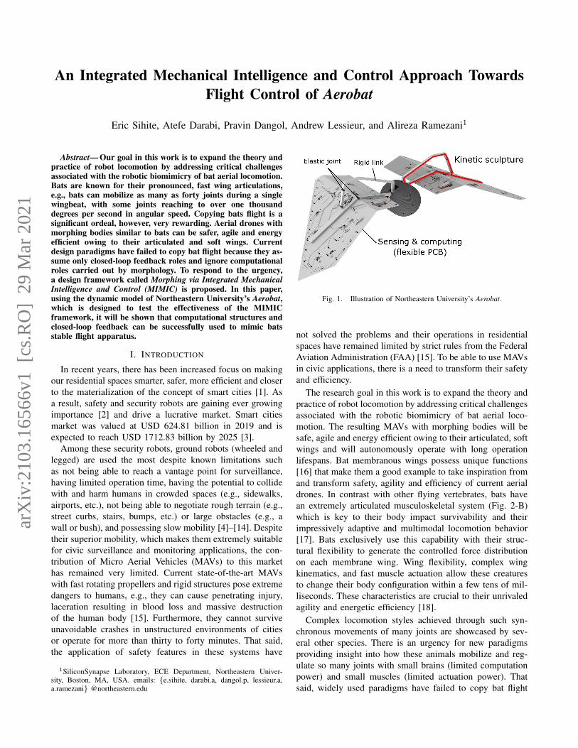
Fig. 1. Illustration of Northeastern University’s Aerobat.
not solved the problems and their operations in residentialspaces have remained limited by strict rules from the FederalAviation Administration (FAA) [15]. To be able to use MAVsin civic applications, there is a need to transform their safetyand efficiency.
The research goal in this work is to expand the theory andpractice of robot locomotion by addressing critical challengesassociated with the robotic biomimicry of bat aerial loco-motion. The resulting MAVs with morphing bodies will besafe, agile and energy efficient owing to their articulated, softwings and will autonomously operate with long operationlifespans. Bat membranous wings possess unique functions[16] that make them a good example to take inspiration fromand transform safety, agility and efficiency of current aerialdrones. In contrast with other flying vertebrates, bats havean extremely articulated musculoskeletal system (Fig. 2-B)which is key to their body impact survivability and theirimpressively adaptive and multimodal locomotion behavior[17]. Bats exclusively use this capability with their struc-tural flexibility to generate the controlled force distributionon each membrane wing. Wing flexibility, complex wingkinematics, and fast muscle actuation allow these creaturesto change their body configuration within a few tens of mil-liseconds. These characteristics are crucial to their unrivaledagility and energetic efficiency [18].
Complex locomotion styles achieved through such syn-chronous movements of many joints are showcased by sev-eral other species. There is an urgency for new paradigmsproviding insight into how these animals mobilize and reg-ulate so many joints with small brains (limited computationpower) and small muscles (limited actuation power). Thatsaid, widely used paradigms have failed to copy bat flight
arX
iv:2
103.
1656
6v1
[cs
.RO
] 2
9 M
ar 2
021
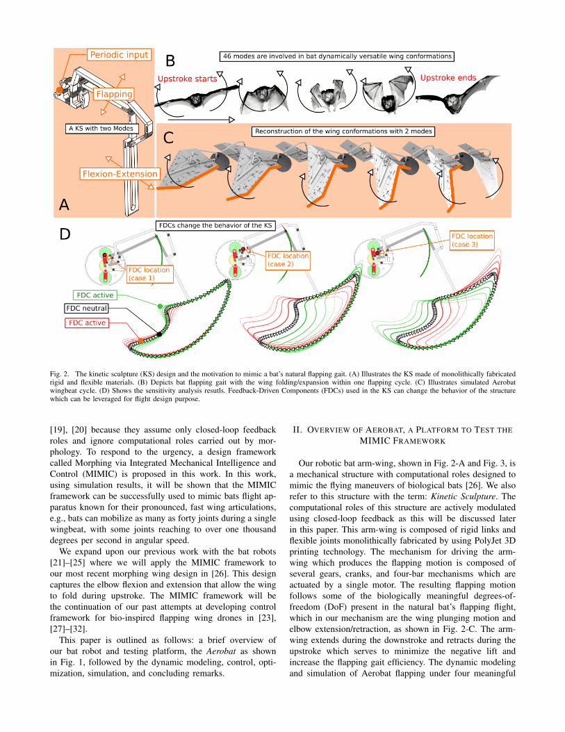
Fig. 2. The kinetic sculpture (KS) design and the motivation to mimic a bat’s natural flapping gait. (A) Illustrates the KS made of monolithically fabricatedrigid and flexible materials. (B) Depicts bat flapping gait with the wing folding/expansion within one flapping cycle. (C) Illustrates simulated Aerobatwingbeat cycle. (D) Shows the sensitivity analysis resutls. Feedback-Driven Components (FDCs) used in the KS can change the behavior of the structurewhich can be leveraged for flight design purpose.
[19], [20] because they assume only closed-loop feedbackroles and ignore computational roles carried out by mor-phology. To respond to the urgency, a design frameworkcalled Morphing via Integrated Mechanical Intelligence andControl (MIMIC) is proposed in this work. In this work,using simulation results, it will be shown that the MIMICframework can be successfully used to mimic bats flight ap-paratus known for their pronounced, fast wing articulations,e.g., bats can mobilize as many as forty joints during a singlewingbeat, with some joints reaching to over one thousanddegrees per second in angular speed.
We expand upon our previous work with the bat robots[21]–[25] where we will apply the MIMIC framework toour most recent morphing wing design in [26]. This designcaptures the elbow flexion and extension that allow the wingto fold during upstroke. The MIMIC framework will bethe continuation of our past attempts at developing controlframework for bio-inspired flapping wing drones in [23],[27]–[32].
This paper is outlined as follows: a brief overview ofour bat robot and testing platform, the Aerobat as shownin Fig. 1, followed by the dynamic modeling, control, opti-mization, simulation, and concluding remarks.
II. OVERVIEW OF AEROBAT, A PLATFORM TO TEST THEMIMIC FRAMEWORK
Our robotic bat arm-wing, shown in Fig. 2-A and Fig. 3, isa mechanical structure with computational roles designed tomimic the flying maneuvers of biological bats [26]. We alsorefer to this structure with the term: Kinetic Sculpture. Thecomputational roles of this structure are actively modulatedusing closed-loop feedback as this will be discussed laterin this paper. This arm-wing is composed of rigid links andflexible joints monolithically fabricated by using PolyJet 3Dprinting technology. The mechanism for driving the arm-wing which produces the flapping motion is composed ofseveral gears, cranks, and four-bar mechanisms which areactuated by a single motor. The resulting flapping motionfollows some of the biologically meaningful degrees-of-freedom (DoF) present in the natural bat’s flapping flight,which in our mechanism are the wing plunging motion andelbow extension/retraction, as shown in Fig. 2-C. The arm-wing extends during the downstroke and retracts during theupstroke which serves to minimize the negative lift andincrease the flapping gait efficiency. The dynamic modelingand simulation of Aerobat flapping under four meaningful
DoFs (plunging, elbow flexion/extension, mediolateral move-ment, and feathering) was investigated in [32] where thewing is modeled as a rigid plate and using optimizationto find a steady flapping gait and upside-down perchingmaneuver.
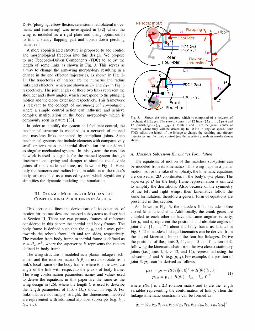
A more sophisticated structure is proposed to add controland morphological freedom into this design. We proposeto use Feedback-Driven Components (FDC) to adjust thelength of some links as shown in Fig. 3. This serves asa way to change the arm-wing morphology resulting in achange in the end effector trajectories, as shown in Fig. 2-D. The trajectories of interest are the humerus and radiuslinks end effectors, which are shown as L5 and L12 in Fig. 3respectively. The joint angles of these two links represent theshoulder and elbow angles, which correspond to the plungingmotion and the elbow extension respectively. This frameworkis relevant to the concept of morphological computation,where a simple control action can influence and achievecomplex manipulation in the body morphology which iscommonly seen in nature [33].
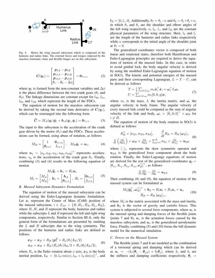
In order to simplify the system and facilitate control, themechanical structure is modeled as a network of massedand massless links connected by compliant joints. Suchmechanical systems that include elements with comparativelysmall or zero mass and inertial distribution are consideredas singular mechanical systems. In this system, the masslessnetwork is used as a guide for the massed system throughlinear/torsional spring and damper to simulate the flexiblejoints of the kinetic sculpture, as shown in Fig. 4. Here,only the humerus and radius links, in addition to the robot’sbody, are modeled as a massed system which significantlysimplifies the dynamic modeling and simulation.
III. DYNAMIC MODELING OF MECHANICALCOMPUTATIONAL STRUCTURES IN AEROBAT
This section outlines the derivations of the equations ofmotion for the massless and massed subsystems as describedin Section II. There are two primary frames of referenceconsidered in this paper: the inertial and body frames. Thebody frame is defined such that the x, y, and z axes pointtowards the robot’s front, left and top sides, respectively.The rotation from body frame to inertial frame is defined asx = RB x
B , where the superscript B represents the vectorsdefined in body frame.
The wing structure is modeled as a planar linkage mech-anism and the rotation matrix R(θ) is used to rotate fromlink’s local frame to the body frame, where θ is the absoluteangle of the link with respect to the y-axis of body frame.The wing conformation parameters names and values usedto derive the equations in this paper are the same as thewing design in [26], where the length li is used to describethe length parameters of link i (Li) shown in Fig. 3. Forlinks that are not simply straight, the dimensions involvedare represented with additional alphabet subscripts (e.g. l3a,l3b, etc).
Fig. 3. Shows the wing structure which is composed of a network ofmechanical linkages. The system consists of 12 links ({L1, . . . , L12}) and17 joints/hinges ({j1, ..., j17}). Joints 1 and 9 are the gears’ center ofrotation where they will be driven up to 10 Hz in angular speed. FourFDCs adjust the length of the linkage to change the resulting end-effectortrajectories and facilitate control (see the sensitivity analysis results shownabove.
A. Massless Subsystem Kinematics Formulation
The equations of motion of the massless subsystem canbe modeled from its kinematics. This wing flaps in a planarmotion, so for the sake of simplicity, the kinematic equationsare derived in 2D coordinates in the body’s y-z plane. Thesuperscript B for the body frame representation is omittedto simplify the derivations. Also, because of the symmetryof the left and right wings, their kinematics follow thesame formulation, therefore a general form of equations arepresented in this section.
As shown in Fig. 3, the massless links includes threeclosed kinematic chains. Additionally, the crank gears arecoupled to each other to have the same angular velocity.Let pi and θi represent the positions and absolute angles ofjoint i ∈ {1, . . . , 17} about the body frame as labeled inFig. 3. The massless linkage kinematics can be derived fromthe closed kinematic loop of the four-bar linkages. Derivethe positions of the joints 3, 11, and 15 as a function of θifollowing the kinematic chain from the two closest stationaryjoints (i.e. joints 1, 4, 9, 12, and 14), represented using thesubscripts A and B, (e.g. p3A). For example, the position ofjoint 3, p3, can be derived as follows
p3A = p1 +R(θ1)[l1, 0]> +R(θ2)[l2, 0]>
p3B = p4 +R(θ4)[−l3a − l3b, 0]>(1)
where R(θi) is a 2D rotation matrix and lj are the lengthvariables representing the conformation of link j. Then thelinkage kinematic constraints can be formed as
q1 = [θ1, θ2, θ4, θ9, θ10, θ12, θ13, θ14, l3b, l3c, l8b, l10b]>
5
6
7
8
17
16Humerus
Link
Radius
Link
Fig. 4. Shows the wing massed subsystem which is composed of thehumerus and radius links. The external forces and torques imposed by themassless kinematic chain and flexible hinges act on this subsystem.
C(q1) =
p3A − p3Bp11A − p11Bp15A − p15Bθ1 − θ9 −∆φ
= 07×1, (2)
where q1 is formed from the non-constant variables and ∆φis the phase difference between the two crank gears (θ1 andθ9). The linkage dimensions are constant except for l3b, l3c,l8b, and l10b which represent the length of the FDCs.
The equation of motion for the massless subsystem canbe derived by taking the second time derivative of C(q1),which can be rearranged into the following form
C = MA(q1)q1 + hA(q1, q1) = 07×1. (3)
The input to this subsystem is the acceleration of the crankgear driven by the motor (θ1) and the FDCs. These acceler-ations can be formed, using abuse of notation, as follows
MB =
[1 01×11
04×7 I4×4
], MB q1 = u1, (4)
where u1 = [ug, u3b, u3c, u8b, u10b]> represents accelera-
tions, ug is the acceleration of the crank gear θ1. Finally,combining (3) and (4) results in the following equation ofmotion
M1q1 + h1 = B1u1
M1 =
[MA
MB
], h1 =
[hA
05×1
], B1 =
[07×5I5×5
](5)
B. Massed Subsystem Dynamics Formulation
The equation of motion of the massed subsystem can bederived using the Euler-Lagrangian dynamic formulation.Let xi represent the Center of Mass (CoM) position ofthe massed subsystem, i ∈ LM = {B,HL, HR, RL, RR},where B, H , and R represent the body, humerus and radiuswhile the subscripts L and R represent the left and right wingcomponents, respectively. Similar to Section III-A, only thegeneral form of the formulations are presented by omittingthe L and R subscripts due to the wing symmetry. Thepositions of the humerus and radius links are defined asfollows
xH = xB +RB (pB7 +Rx(θ7) lH/2)
xR = xH +RB (Rx(θ7) lH/2 +Rx(θ8) lR/2),(6)
where Rx is the Euler rotation about x axis, xB is the bodyinertial position, lH = [0, lh cos(α), l5b + lh sin(α)]>, and
lR = [0, lr, 0]. Additionally, θ7 = θs−α and θ8 = θe+θs+α,in which θs and θe are the shoulder and elbow angles ofthe left wing respectively. α, lh, lr, and l5b are the constantphysical parameters of the wing structure. Here, lh and lrare the length of the humerus and radius links respectivelywhile α corresponds to the initial angle of the shoulder jointat θ7 = 0.
The generalized coordinates vector is composed of bothlinear and rotational states, therefore both Hamiltonian andEuler-Lagrangian principles are required to derive the equa-tions of motion of the massed links. In this case, in orderto avoid gimbal lock, the body angular velocity is derivedby using the modified Euler-Lagrangian equation of motionin SO(3). The kinetic and potential energies of the massedparts and their corresponding Lagrangian, L = T − U , canbe derived as follows
T = 12
∑i∈LM
mix>i xi + ω>i Iiωi
U =∑i∈LM
mi[0, 0, g]xi(7)
where mi is the mass, Ii the inertia matrix, and ωi theangular velocity in body frame. The angular velocity ofevery massed link could be computed as the sum of angularvelocity of the link and body, ωi = [θi, 0, 0]> + ωB fori 6= B.
The equation of motion of the body rotation in SO(3) isdefined as follows
R>B = [rB1, rB2, rB3],d
dtRB = RB [ωB ]×
ddt
(∂L∂ωB
)+ ωB × ∂L
∂ωB+∑3j=1 rBj ×
∂L∂rBj
= u2B
(8)
where [ · ]× represents the skew symmetric operator andu2B is the generalized force component about the bodyrotation. Finally, the Euler-Lagrange equations of motionare derived for the rest of the generalized coordinates q2 =[θsL , θeL , θsR , θeR ,x
>B ]>, as follows
ddt
∂L∂q2− ∂L
∂q2= u2A. (9)
Then combining (8) and (9), the equation of motion of themassed system can be formulated as
M2[q>2 , ω>B ]> + h2 = Biui +Bsus + ua
RB = RB [ωB ]×,(10)
where M2 is the matrix associated with the mass and inertia,and h2 is the vector of gravity and coriolis forces. Thissystem is subjected to several force components, where ui isthe internal spring and damping forces of the flexible joints(joints 7 and 8), us is the actuation forces caused by themassless subsystem, and ua is the generalized aerodynamicforce. Finally, combining (5) and (10) forms the full dynamicmodel for the numerical simulation.
C. Forces on the Massed System
The flexible joints 7 and 8 are modeled as the combinationof a torsional spring and damping which can be derivedas ui = −(ki(θj − θj,0) + biθj), where ki and bi arethe stiffness and damping coefficients respectively, θj =
Body
Kinetic Sculpture
Simpli ed wing surface model
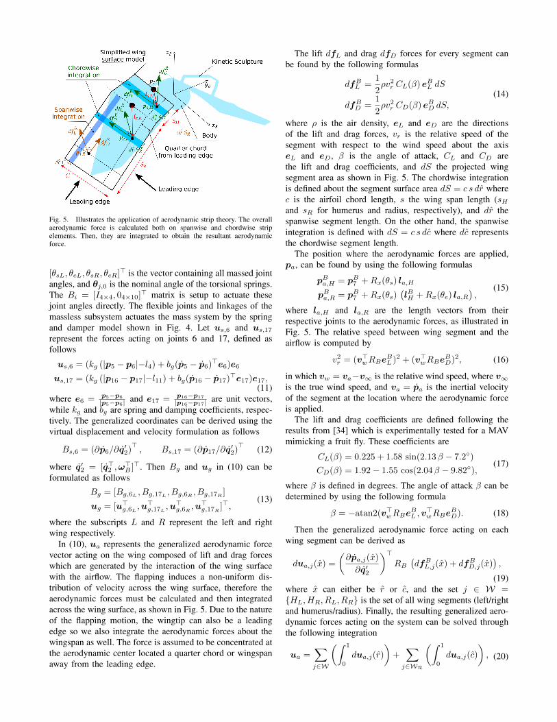
Fig. 5. Illustrates the application of aerodynamic strip theory. The overallaerodynamic force is calculated both on spanwise and chordwise stripelements. Then, they are integrated to obtain the resultant aerodynamicforce.
[θsL, θeL, θsR, θeR]> is the vector containing all massed jointangles, and θj,0 is the nominal angle of the torsional springs.The Bi = [I4×4, 04×10]> matrix is setup to actuate thesejoint angles directly. The flexible joints and linkages of themassless subsystem actuates the mass system by the springand damper model shown in Fig. 4. Let us,6 and us,17represent the forces acting on joints 6 and 17, defined asfollows
us,6 = (kg (|p5 − p6|−l4) + bg(p5 − p6)>e6)e6
us,17 = (kg (|p16 − p17|−l11) + bg(p16 − p17)>e17)e17,(11)
where e6 = p5−p6
|p5−p6| and e17 = p16−p17
|p16−p17| are unit vectors,while kg and bg are spring and damping coefficients, respec-tively. The generalized coordinates can be derived using thevirtual displacement and velocity formulation as follows
Bs,6 = (∂p6/∂q′2)>, Bs,17 = (∂p17/∂q
′2)> (12)
where q′2 = [q>2 ,ω>B ]>. Then Bg and ug in (10) can be
formulated as follows
Bg = [Bg,6L , Bg,17L , Bg,6R , Bg,17R ]
ug = [u>g,6L ,u>g,17L ,u
>g,6R ,u
>g,17R ]>,
(13)
where the subscripts L and R represent the left and rightwing respectively.
In (10), ua represents the generalized aerodynamic forcevector acting on the wing composed of lift and drag forceswhich are generated by the interaction of the wing surfacewith the airflow. The flapping induces a non-uniform dis-tribution of velocity across the wing surface, therefore theaerodynamic forces must be calculated and then integratedacross the wing surface, as shown in Fig. 5. Due to the natureof the flapping motion, the wingtip can also be a leadingedge so we also integrate the aerodynamic forces about thewingspan as well. The force is assumed to be concentrated atthe aerodynamic center located a quarter chord or wingspanaway from the leading edge.
The lift dfL and drag dfD forces for every segment canbe found by the following formulas
dfBL =1
2ρv2r CL(β) eBL dS
dfBD =1
2ρv2r CD(β) eBD dS,
(14)
where ρ is the air density, eL and eD are the directionsof the lift and drag forces, vr is the relative speed of thesegment with respect to the wind speed about the axiseL and eD, β is the angle of attack, CL and CD arethe lift and drag coefficients, and dS the projected wingsegment area as shown in Fig. 5. The chordwise integrationis defined about the segment surface area dS = c s dr wherec is the airfoil chord length, s the wing span length (sHand sR for humerus and radius, respectively), and dr thespanwise segment length. On the other hand, the spanwiseintegration is defined with dS = c s dc where dc representsthe chordwise segment length.
The position where the aerodynamic forces are applied,pa, can be found by using the following formulas
pBa,H = pB7 +Rx(θs) la,H
pBa,R = pB7 +Rx(θs)(lBH +Rx(θe) la,R
),
(15)
where la,H and la,R are the length vectors from theirrespective joints to the aerodynamic forces, as illustrated inFig. 5. The relative speed between wing segment and theairflow is computed by
v2r = (v>wRBeBL )2 + (v>wRBe
BD)2, (16)
in which vw = va−v∞ is the relative wind speed, where v∞is the true wind speed, and va = pa is the inertial velocityof the segment at the location where the aerodynamic forceis applied.
The lift and drag coefficients are defined following theresults from [34] which is experimentally tested for a MAVmimicking a fruit fly. These coefficients are
CL(β) = 0.225 + 1.58 sin(2.13β − 7.2◦)
CD(β) = 1.92− 1.55 cos(2.04β − 9.82◦),(17)
where β is defined in degrees. The angle of attack β can bedetermined by using the following formula
β = −atan2(v>wRBeBL ,v
>wRBe
BD). (18)
Then the generalized aerodynamic force acting on eachwing segment can be derived as
dua,j(x) =
(∂pa,j(x)
∂q′2
)>RB
(dfBL,j(x) + dfBD,j(x)
),
(19)where x can either be r or c, and the set j ∈ W ={HL, HR, RL, RR} is the set of all wing segments (left/rightand humerus/radius). Finally, the resulting generalized aero-dynamic forces acting on the system can be solved throughthe following integration
ua =∑j∈W
(∫ 1
0
dua,j(r)
)+∑j∈WR
(∫ 1
0
dua,j(c)
), (20)
where the set WR = {RL, RR} is the set of the radius wingsegments.
IV. CONTROLLER DESIGN, OPTIMIZATION, ANDNUMERICAL SIMULATION
The wing mechanism is controlled by adjusting the flap-ping rate and the length of the FDCs, which are the com-ponents of the massless subsystem, through the input u1 in(5). In this view, kinetic sculptures deliver dynamic morphingcapabilities which are the key features in bats flight apparatuswhile FDCs take supervisory roles to stabilize the flightdynamics. Let θ1 be the speed of the motor driven crankgear while l = [l3b, l3c, l8b, l10b]
> be the vector containingthe length of FDCs. The flapping frequency and the FDClengths can be adjusted by a simple PD controller as shownbelow
ug = Kd1(ωref − θ1)
up = Kp2 (lref − l)−Kd2 l,(21)
where Kpi and Kdi are the control gains, ωref is the desiredflapping frequency, up = [u3b, u3c, u8b, u10b]
>, and lref isthe desired FDC length vector. The flapping rate is set to bea constant value of 10 Hz which is the approximate flappingfrequency of the Egyptian fruit bat (rousettus aegyptiacus)which is the basis of our robot’s design. On the other hand,the lref is found using optimization framework which willbe outlined in the following sections.
A. Open Loop Gait Optimization
This optimization is setup to find a gait which has astable limit cycle by optimizing the body initial pitch andFDC lengths. The FDC lengths are set to be constant in thisoptimization, which results in a periodic flapping gait withno feedback stabilization. The feedback into the system willbe added after this stable limit cycle is found which will beoutlined in the next section.
The cost function for the optimization is determined froma numerical simulation done over a set period of time.Let the time evolution of the simulated states be xk+1 =f(xk, lref,k,uk), where the simulation states xk contains allof the relevant states from the equation of motions derivedin Section III. The angular momentum is used as a metricto stabilize the flapping gait which is derived using thefollowing formulations
Π =∑i∈LM
RB Ii ωi −mi(xi − xCoM )× xi, (22)
where xCoM represents the averaged CoM position of theentire robot. Then the stable limit cycle is found by solvingthe following optimization problem:
minlref ,θy
J =
N∑k=1
(w1 Π>k Πk + w2 x>B,k xB,k) ∆t
s.t. lmin ≤ lref ≤ lmax,(23)
where the cost J is setup to minimize the angular momentumΠ and body velocity xB , θy is the initial pitch angle, lminand lmax are the bounds on lref , ∆t is the simulation timestep, N is the simulation final step, and wi is the weight
0 0.5 1 1.5 2 2.5 3 3.5 4
-4
-2
0V
el (m
/s)
Body Velocity
x
y
z
airspeed x
0 0.5 1 1.5 2 2.5 3 3.5 4
Time (s)
-20
0
20
40
60
80
An
gle
s (
de
g)
Body Euler Anglesroll
pitch
yaw
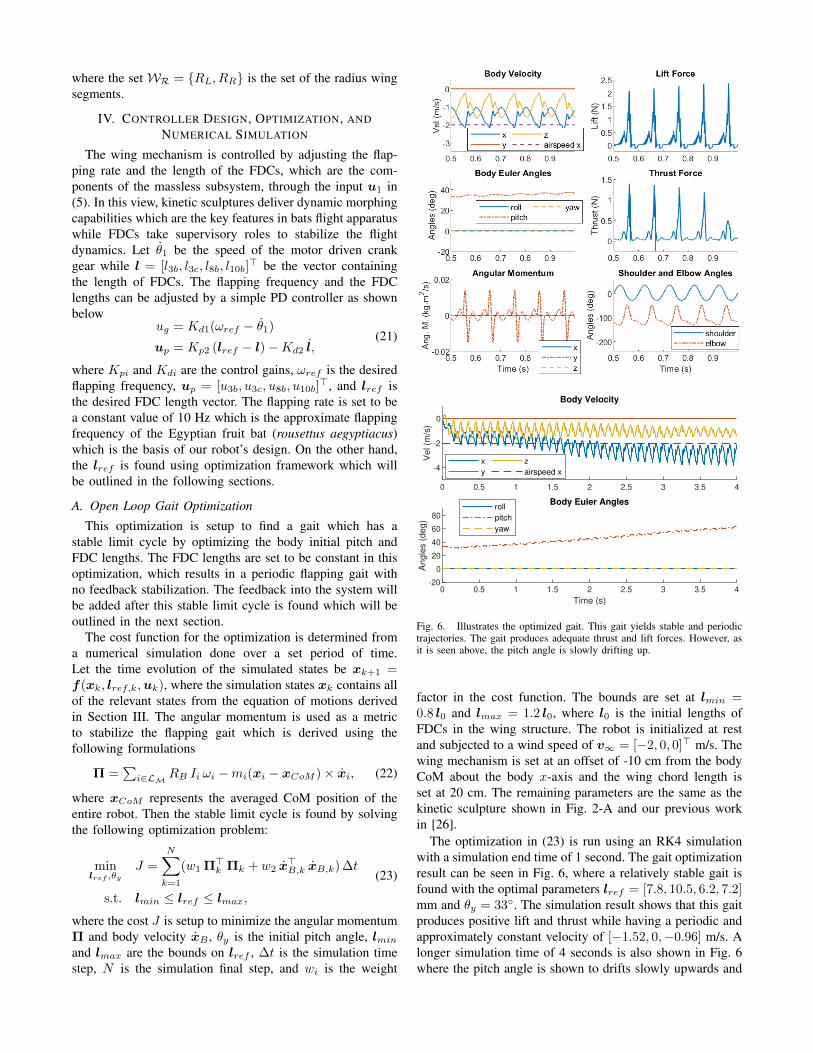
Fig. 6. Illustrates the optimized gait. This gait yields stable and periodictrajectories. The gait produces adequate thrust and lift forces. However, asit is seen above, the pitch angle is slowly drifting up.
factor in the cost function. The bounds are set at lmin =0.8 l0 and lmax = 1.2 l0, where l0 is the initial lengths ofFDCs in the wing structure. The robot is initialized at restand subjected to a wind speed of v∞ = [−2, 0, 0]> m/s. Thewing mechanism is set at an offset of -10 cm from the bodyCoM about the body x-axis and the wing chord length isset at 20 cm. The remaining parameters are the same as thekinetic sculpture shown in Fig. 2-A and our previous workin [26].
The optimization in (23) is run using an RK4 simulationwith a simulation end time of 1 second. The gait optimizationresult can be seen in Fig. 6, where a relatively stable gait isfound with the optimal parameters lref = [7.8, 10.5, 6.2, 7.2]mm and θy = 33◦. The simulation result shows that this gaitproduces positive lift and thrust while having a periodic andapproximately constant velocity of [−1.52, 0,−0.96] m/s. Alonger simulation time of 4 seconds is also shown in Fig. 6where the pitch angle is shown to drifts slowly upwards and
0 0.5 1 1.5 2 2.5 3 3.5 4-4
-2
0
2V
el (m
/s)
Body Velocityx
y
z
airspeed x
0 0.5 1 1.5 2 2.5 3 3.5 4-20
0
20
40
60
Eu
ler
An
gle
s (
de
g)
Body Euler Angles
roll
pitch
yaw
pitch ref
0 0.5 1 1.5 2 2.5 3 3.5 4
0
1
2
Fo
rce
(N
)
Lift and Thrust Force (Body Frame)
lift
thrust
0 0.5 1 1.5 2 2.5 3 3.5 4-150
-100
-50
0
50
An
gle
s (
de
g)
Shoulder and Elbow Angles
shoulder
elbow
0 0.5 1 1.5 2 2.5 3 3.5 4
Time (s)
0
0.5
1
1.5
Le
ng
th (
cm
)
FDC Lengths
l3b
l3c
l8b
l10b
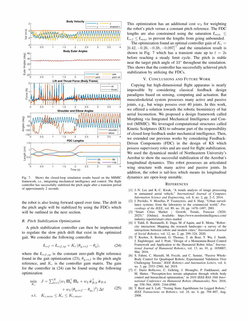
Fig. 7. Shows the closed-loop simulation results based on the MIMICframework, i.e., integrating mechanical intelligence and control. The flightcontroller has successfully stabilized the pitch angle after a transient periodof approximately 2 seconds.
the robot is also losing forward speed over time. The drift inthe pitch angle will be stabilized by using the FDCs whichwill be outlined in the next section.
B. Pitch Stabilization Optimization
A pitch stabilization controller can then be implementedto regulate the slow pitch drift that exist in the optimizedgait. We consider the following controller
lref = lref,zp +Kc (θy,ref − θy), (24)
where the lref,zp is the constant zero-path flight referencefound in the gait optimization (23), θy,ref is the pitch anglereference, and Kc is the controller gain matrix. The gainfor the controller in (24) can be found using the followingoptimization
minKc
J =∑Nk=1(w1 Π>k Πk + w2 x
>B,k xB,k
+ w3 (θy,ref − θyk)2) ∆t
s.t. Kc,min ≤ Kc ≤ Kc,max.
(25)
This optimization has an additional cost w3 for weightingthe robot’s pitch versus a constant pitch reference. The FDClengths are also constrained using the saturation lmin ≤lref ≤ lmax to prevent the lengths from going unbounded.
The optimization found an optimal controller gain of Kc =[0.42,−0.26,−0.38,−0.097]> and the simulation result isshown in Fig. 7 which has a transient state up to t = 2sbefore reaching a steady limit cycle. The pitch is stablenear the target pitch angle of 33◦ throughout the simulation.This shows that the controller has successfully achieved pitchstabilization by utilizing the FDCs.
V. CONCLUSIONS AND FUTURE WORK
Copying bat high-dimensional flight apparatus is nearlyimpossible by considering classical feedback designparadigms based on sensing, computing and actuation. Batmusculoskeletal system possesses many active and passivejoints, e.g., bat wings possess over 40 joints. In this work,we offered a solution towards the robotic biomimicry of bataerial locomotion. We proposed a design framework calledMorphing via Integrated Mechanical Intelligence and Con-trol (MIMIC). We leveraged computational structures calledKinetic Sculptures (KS) to subsume part of the responsibilityof closed-loop feedback under mechanical intelligence. Then,we extended our previous works by considering Feedback-Driven Components (FDC) in the design of KS whichpossess supervisory roles and are used for flight stabilization.We used the dynamical model of Northeastern University’sAerobat to show the successful stabilization of the Aerobat’slongitudinal dynamics. This robot possesses an articulatedwing structure with many active and passive joints. Inaddition, the robot is tail-less which means its longitudinaldynamics are open-loop unstable.
REFERENCES
[1] J.-N. Lee and K.-C. Kwak, “A trends analysis of image processingin unmanned aerial vehicle,” International Journal of Computer,Information Science and Engineering, vol. 8, no. 2, pp. 2–5, 2014.
[2] I. Pavlidis, V. Morellas, P. Tsiamyrtzis, and S. Harp, “Urban surveil-lance systems: from the laboratory to the commercial world,” Pro-ceedings of the IEEE, vol. 89, no. 10, pp. 1478–1497, 2001.
[3] “Smart Cities Market | Growth, Trends, Forecast (2020-2025).” [Online]. Available: https://www.mordorintelligence.com/industry-reports/smart-cities-market
[4] I. Tiddi, E. Bastianelli, E. Daga, M. d’Aquin, and E. Motta, “Robot–city interaction: Mapping the research landscape—a survey of theinteractions between robots and modern cities,” International Journalof Social Robotics, vol. 12, no. 2, pp. 299–324, 2020.
[5] T. Koolen, S. Bertrand, G. Thomas, T. de Boer, T. Wu, J. Smith,J. Englsberger, and J. Pratt, “Design of a Momentum-Based ControlFramework and Application to the Humanoid Robot Atlas,” Interna-tional Journal of Humanoid Robotics, vol. 13, no. 01, p. 1650007,Mar. 2016.
[6] S. Fahmi, C. Mastalli, M. Focchi, and C. Semini, “Passive Whole-Body Control for Quadruped Robots: Experimental Validation OverChallenging Terrain,” IEEE Robotics and Automation Letters, vol. 4,no. 3, pp. 2553–2560, Jul. 2019.
[7] C. Dario Bellicoso, C. Gehring, J. Hwangbo, P. Fankhauser, andM. Hutter, “Perception-less terrain adaptation through whole bodycontrol and hierarchical optimization,” in 2016 IEEE-RAS 16th Inter-national Conference on Humanoid Robots (Humanoids), Nov. 2016,pp. 558–564, iSSN: 2164-0580.
[8] T. Bretl and S. Lall, “Testing Static Equilibrium for Legged Robots,”IEEE Transactions on Robotics, vol. 24, no. 4, pp. 794–807, Aug.2008.
[9] D. Pardo, L. Moller, M. Neunert, A. W. Winkler, and J. Buchli,“Evaluating Direct Transcription and Nonlinear Optimization Methodsfor Robot Motion Planning,” IEEE Robotics and Automation Letters,vol. 1, no. 2, pp. 946–953, Jul. 2016.
[10] C. Mastalli, M. Focchi, I. Havoutis, A. Radulescu, S. Calinon,J. Buchli, D. G. Caldwell, and C. Semini, “Trajectory and footholdoptimization using low-dimensional models for rough terrain loco-motion,” in 2017 IEEE International Conference on Robotics andAutomation (ICRA), May 2017, pp. 1096–1103.
[11] C. Mastalli, I. Havoutis, A. W. Winkler, D. G. Caldwell, and C. Sem-ini, “On-line and on-board planning and perception for quadrupedallocomotion,” in 2015 IEEE International Conference on Technologiesfor Practical Robot Applications (TePRA), May 2015, pp. 1–7.
[12] A. W. Winkler, C. D. Bellicoso, M. Hutter, and J. Buchli, “Gaitand Trajectory Optimization for Legged Systems Through Phase-Based End-Effector Parameterization,” IEEE Robotics and AutomationLetters, vol. 3, no. 3, pp. 1560–1567, Jul. 2018.
[13] B. Aceituno-Cabezas, C. Mastalli, H. Dai, M. Focchi, A. Radulescu,D. G. Caldwell, J. Cappelletto, J. C. Grieco, G. Fernandez-Lopez,and C. Semini, “Simultaneous Contact, Gait, and Motion Planningfor Robust Multilegged Locomotion via Mixed-Integer Convex Opti-mization,” IEEE Robotics and Automation Letters, vol. 3, no. 3, pp.2531–2538, Jul. 2018.
[14] H. Dai and R. Tedrake, “Planning robust walking motion on uneventerrain via convex optimization,” in 2016 IEEE-RAS 16th InternationalConference on Humanoid Robots (Humanoids), Nov. 2016, pp. 579–586, iSSN: 2164-0580.
[15] D. Arterburn, M. Ewing, R. Prabhu, F. Zhu, D. Francis et al., “Faa uascenter of excellence task a4: Uas ground collision severity evaluation.”2017.
[16] H. Tanaka, H. Okada, Y. Shimasue, and H. Liu, “Flexible flappingwings with self-organized microwrinkles,” Bioinspiration & Biomimet-ics, vol. 10, no. 4, p. 046005, 2015.
[17] D. K. Riskin, D. J. Willis, J. Iriarte-Dıaz, T. L. Hedrick, M. Kostandov,J. Chen, D. H. Laidlaw, K. S. Breuer, and S. M. Swartz, “Quantify-ing the complexity of bat wing kinematics,” Journal of TheoreticalBiology, vol. 254, no. 3, pp. 604–615, 2008.
[18] A. Azuma, The biokinetics of flying and swimming. Springer Science& Business Media, 2012.
[19] J. W. Bahlman, S. M. Swartz, and K. S. Breuer, “Design andcharacterization of a multi-articulated robotic bat wing,” Bioinspiration& Biomimetics, vol. 8, no. 1, p. 016009, 2013.
[20] J. Colorado, A. Barrientos, C. Rossi, and K. S. Breuer, “Biomechanicsof smart wings in a bat robot: morphing wings using sma actuators,”Bioinspiration & biomimetics, vol. 7, no. 3, p. 036006, 2012.
[21] A. Ramezani, S.-J. Chung, and S. Hutchinson, “A biomimetic roboticplatform to study flight specializations of bats,” Science Robotics,vol. 2, no. 3, 2017.
[22] J. Hoff, A. Ramezani, S.-J. Chung, and S. Hutchinson, “Synergisticdesign of a bio-inspired micro aerial vehicle with articulated wings.”in Robotics: science and systems, 2016.
[23] J. Hoff, A. Ramezani, S.-J. Chung, and S. Hutchinson, “Optimizingthe structure and movement of a robotic bat with biological kinematicsynergies,” The International Journal of Robotics Research, vol. 37,no. 10, pp. 1233–1252, 2018.
[24] J. Hoff, A. Ramezani, S.-J. Chung, and S. Hutchinson, “Reducingversatile bat wing conformations to a 1-dof machine,” in Conferenceon Biomimetic and Biohybrid Systems. Springer, 2017, pp. 181–192.
[25] A. Ramezani, “Towards biomimicry of a bat-style perching maneuveron structures: the manipulation of inertial dynamics,” in 2020 IEEEInternational Conference on Robotics and Automation (ICRA). IEEE,2020, pp. 7015–7021.
[26] E. Sihite, P. Kelly, and A. Ramezani, “Computational structure designof a bio-inspired armwing mechanism,” IEEE Robotics and Automa-tion Letters, vol. 5, no. 4, pp. 5929–5936, 2020.
[27] A. Ramezani, X. Shi, S.-J. Chung, and S. Hutchinson, “Lagrangianmodeling and flight control of articulated-winged bat robot,” in 2015IEEE/RSJ International Conference on Intelligent Robots and Systems(IROS). IEEE, 2015, pp. 2867–2874.
[28] J. Hoff, U. Syed, A. Ramezani, and S. Hutchinson, “Trajectoryplanning for a bat-like flapping wing robot,” in 2019 IEEE/RSJInternational Conference on Intelligent Robots and Systems (IROS).IEEE, 2019, pp. 6800–6805.
[29] A. Ramezani, X. Shi, S.-J. Chung, and S. Hutchinson, “Nonlinearflight controller synthesis of a bat-inspired micro aerial vehicle,” inAIAA Guidance, Navigation, and Control Conference, 2016, p. 1376.
[30] A. Ramezani, S. U. Ahmed, J. Hoff, S.-J. Chung, and S. Hutchinson,“Describing robotic bat flight with stable periodic orbits,” in Con-ference on Biomimetic and Biohybrid Systems. Springer, 2017, pp.394–405.
[31] U. A. Syed, A. Ramezani, S.-J. Chung, and S. Hutchinson, “Fromrousettus aegyptiacus (bat) landing to robotic landing: Regulation ofcg-cp distance using a nonlinear closed-loop feedback,” in 2017 IEEEInternational Conference on Robotics and Automation (ICRA). IEEE,2017, pp. 3560–3567.
[32] E. Sihite and A. Ramezani, “Enforcing nonholonomic constraintsin aerobat, a roosting flapping wing model,” in 2020 59th IEEEConference on Decision and Control (CDC). IEEE, 2020, pp. 5321–5327.
[33] H. Hauser, A. J. Ijspeert, R. M. Fuchslin, R. Pfeifer, and W. Maass,“The role of feedback in morphological computation with compliantbodies,” Biological cybernetics, vol. 106, no. 10, pp. 595–613, 2012.
[34] S. P. Sane and M. H. Dickinson, “The control of flight force bya flapping wing: lift and drag production,” Journal of experimentalbiology, vol. 204, no. 15, pp. 2607–2626, 2001.


![SAP NetWeaver Business Intelligence Integrated Planning[1]](https://img.pdfslide.us/doc/110x75/55cf97f6550346d03394b4b7/sap-netweaver-business-intelligence-integrated-planning1.jpg)