Embed Size (px)
Citation preview

HAL Id: hal-01765257https://hal.inria.fr/hal-01765257
Submitted on 12 Apr 2018
HAL is a multi-disciplinary open accessarchive for the deposit and dissemination of sci-entific research documents, whether they are pub-lished or not. The documents may come fromteaching and research institutions in France orabroad, or from public or private research centers.
L’archive ouverte pluridisciplinaire HAL, estdestinée au dépôt et à la diffusion de documentsscientifiques de niveau recherche, publiés ou non,émanant des établissements d’enseignement et derecherche français ou étrangers, des laboratoirespublics ou privés.
Distributed under a Creative Commons Attribution| 4.0 International License
An Integrated Enterprise Modeling Framework Usingthe RUP/UML Business Use-Case Model and BPMN
Yves Wautelet, Stephan Poelmans
To cite this version:Yves Wautelet, Stephan Poelmans. An Integrated Enterprise Modeling Framework Using theRUP/UML Business Use-Case Model and BPMN. 10th IFIP Working Conference on The Practiceof Enterprise Modeling (PoEM), Nov 2017, Leuven, Belgium. pp.299-315, �10.1007/978-3-319-70241-4_20�. �hal-01765257�

An Integrated Enterprise Modeling Framework usingthe RUP/UML Business Use-Case Model and BPMN
Yves Wautelet and Stephan Poelmans
KU Leuven, Belgiumyves.wautelet, [email protected],
Abstract. Various frameworks are available for modeling an organizational set-ting. Their constituting models nevertheless mostly choose a particular decisionlevel to represent perceived reality meaning that some introduce coarse-grained(i.e. abstract) elements and some others fine-grained (i.e. detailed) ones. Some-times, in a same model, elements of various levels of granularity can be mixedlike for example in the i* strategic rationale model. The main drawback is thatthis leads to hard to read and complex models, not ideal for easy and quick un-derstanding of the software problem. Also, within the industry, poor unificationin the use of models does exist. The various Unified Modeling Language (UML)models and the Business Process Model and Notation (BPMN) are neverthelessrather popular. In this paper, we study the use of the Business Use Case Model– an extension of the classical UML use-case model defined in the Rational Uni-fied Process (RUP) – and the BPMN Business Process Model (BPM) as a unifiedframework for knowledge representation at strategic, tactical and operational lev-els. By default, the RUP advises to use UML activity diagrams for operational-level knowledge representation. Their main drawback is that they have been en-gineered to model software behavior with respect to the user and not businessprocess modeling at large. The BPMN BPM thus offers more perspectives forpure business process modeling; that is why it mostly used in the industry for thispurpose. The use of these models in a unified way is ensured by traceability atthe various levels of modeling.
Keywords: Business Use-Case Model, Business Modeling, BPMN, Business Goal.
1 Introduction
1.1 Research Context
Business (often refereed to as enterprise) modeling provides guidance for the analyston how to understand and represent the organizational setting through all of its pro-cesses. As-is process understanding is required for further process re-engineering ordetermining possible software systems support. In order to furnish adequate models tosupport such an activity, we need to model different levels of abstraction. Traditionally,a company structures around three (complementary) abstraction (or decision) levels –the strategic, tactical and operational level – each one requiring representation mod-els. Furthermore, guidance for a follow-up between all hierarchy levels is required; i.e.knowledge must – at least partially – be refined and traceable.

2 Yves Wautelet and Stephan Poelmans
Within the the Rational Unified Process (RUP) [10, 25, 12], the RUP/UML BusinessUse-Case Model1 (BUCM) offers a syntax and semantic to represent the situation as-isat tactical and (at least partially2) strategic level. The BUCM is, indeed, an extensionof the Unified Modeling Language (UML) [17] Use-Case Model supported by the RUPand many Computer Aided Software Engineering (CASE) tools. Then, at the operationallevel, the representation is ensured by the UML activity model as defined in the OMGspecification (see [17]). These are, nevertheless, primarily designed to document theto-be system behavior through the interaction with users. RUP defines no alignment(anchoring of elements) between the tactical and operational levels.
1.2 Towards the combined use of the RUP/UML Business Use Case Model andthe BPMN Business Process Model
The RUP/UML BUCM and the Business Process Modeling Notation (BPMN) [16, 1,26] Business Process Model (BPM) 3 have in common that they are targeted to purebusiness process modeling so that they dispose of a richer set of elements associatedwith precise semantics for this purpose. Even if they come from different semantic do-mains, some elements are semantically close enough and they can be used for anchoring(and traceability) among representation levels. That is why, previous research (see [29])studies the possible anchoring between the RUP/UML BUCM and the BPMN BPM.
The conjunct use of these two frameworks is supported by CASE-tools like RationalSoftware Architect [23] or Visual Paradigm [18].
1.3 Research Context and Objective
As evoked, [29] evaluates the possible anchoring between the RUP/UML BUCM andBPMN BPM, but focuses exclusively on tactical and operational levels representation.It does not detail the strategic level and is thus an incomplete solution for full businessmodeling knowledge levels coverage.
The research developed in this paper further justifies the choice of the integrationof the two frameworks and furnishes a meta-model for the full integration of the 2frameworks and their use for knowledge representation and traceability among the threeknowledge level representations. This unified-model has been used within the context ofthe Design of a Business Information System (DBIS) course within the Master in Busi-ness Information Systems (faculty of economics and business) at KU Leuven (campusBrussels). Further justification of the choices for framework selection can be found inSection 2. We specifically wanted to adopt BPMN BPM within the as-is business pro-cess modeling of a case study given to students. Within the context of the course, we
1 We do not refer here to the use case model as defined by the OMG in [17] but to the refinementproposed in the business modeling discipline from the RUP (see [10, 25, 8, 12, 15]). That iswhy, in this paper, we refer to it as the RUP/UML Business Use-Case Model.
2 The strategic elements within the BUCM are the business goal and objective (see Section 5).3 Note that we do not include the BPMN Process Maps in our study but only the Business
Process Model (i.e. the classical workflow), see Section 3. Also, when we refer to the BPMNBPM, we refer to the entire theoretical set of elements defined by the OMG while when werefer to a BPMN process diagram we refer to an instance of the model (applied to a case).

Integrated Enterprise Modeling using the RUP/UML BCM and BPMN 3
(the teachers) have initially decided to integrate the use of the BPMN BPM for processoperational level representation instead of the UML activity model because:
– The BPMN BPM offers a set of (relevant) stereotypes with associated semantics torepresent business processes in an operational manner because these were primarilyengineered for enterprise modeling. The activity model does not offer these; thismisalignment comes from the fact that they have been engineered to model userbehavior with respect to a to-be software system;
– The BPMN BPM is an increasingly important industry standard for enterprise mod-eling (see [14]);
– The BPMN BPM offers the possibility to easily execute modeled workflows with alanguage as the Business Process Execution Language (BPEL, see [21, 19, 20, 5]);
– Further extensions of the BPMN BPM include the definition of Key PerformanceIndicators (e.g. [7]) that could be applied to the BPMN BPM in our approach toevaluate their support to tactical and strategic aspect(s). This is left for future work.
Finally, poor (we could even say no) documentation and support is offered for theuse of strategic modeling within the RUP/UML BUCM. That is why we distinguishhere the strategic modeling level as a separate diagram to be built in parallel with theclassical (business) use case model and allowing to trace the impact of processes (i.e.business use-cases) on the long term strategic goals and objectives. This is discussed inSection 5.
1.4 Added Value of Defining Anchoring Points between the RUP/UML BusinessUse Case Model and the BPMN Business Process Model
The set of elements defined by the BPMN BPM allows better anchoring between theoperational and tactical levels than the classical UML activity model. A preliminaryquestion is, however, the utility of defining such anchoring points to ensure traceabilitybetween the different abstraction levels. We highlight the following benefits:
– Ensure consistency during the refinement process. Providing anchoring points ofelements from the models at the different abstraction levels helps to ensure thatthe vision of the reality built and shown in the different models (thus at differentknowledge levels) is aligned rather than divergent. In other words, it allows buildingcomplementary models envisioning reality with the same perspective rather thanbuilding concurrent models envisioning reality with various perspectives;
– Giving guidelines to modelers. By defining a set of anchoring points, modelersdispose of a clear set of guidelines for building and structuring their models; this isvery useful for novice modelers (see Section 1.5);
– Simplify the structuring in the refinement process. A set of elements present at thetactical level need to be present at the operational level, these can immediately beincluded in the operational view simplifying the structuring of diagrams;
– Help communicating with stakeholders. The correct use of the anchoring guidelinesallows to explain and justify modeling choices when communicating the producedmodels to stakeholders.
As said, the definition of these anchoring points has been done in [29] and aresummarized in Section 4.

4 Yves Wautelet and Stephan Poelmans
1.5 Added Value of the Integrated Framework and ContributionsAs said, the integrated framework presented in this paper has been developed and ap-plied in the context of an applied software engineering course at master level. When thecourse was initially defined and given, the BPMN BPM was integrated in the BusinessModeling discipline of the RUP for operational workflow representation but withoutspecific anchoring points with the RUP/UML BUCM. During the two first academicyears, the teachers only gave the indication to use the BPMN BPM instead of the UMLactivity model in order to practice skills with the former framework (it was judged rel-evant for the reasons evoked previously). The course format stipulates that students re-ceive real-life process descriptions (submitted to a major consultancy company, partnerin the students’ solutions evaluation) and have to produce an initial as-is representa-tion of the business processes. In practice, when modeling the case, students made alot of round-trip between the abstraction levels (thus the RUP/UML BUC diagram andthe BPMN process diagrams) while understanding and modeling the processes. Thisresulted often in a poor linkage between the tactical and operational diagrams. Whenquestioned about it, students could hardly relate the different modeling levels and jus-tify their choices. In the next (and last) two academic years, students received theoreti-cal information about the anchoring points and could use these as modeling guidelinesleading to more consistent models and the ability to justify some modeling choices. Aformal evaluation of this is left for future work.
The primary contribution of this paper is the meta-model furnishing an integratedview for the conjunct use of the RUP/UML BUCM and the BPMN BPM; this one isintended to be used as guideline for the building diagrams documenting the organizationand its processes on three layers (see Section 5).
The goal is not (necessarily) to push the adoption of “our integrated framework”into the industry but to teach business process modeling as a prerequisite in softwaredevelopment using industry adopted practices. This paper highlights possible anchoringbetween the frameworks to force the modeler to consider traceability when depictingthe three knowledge (or decision) levels of an organization increasing the level of con-sistency between levels.
1.6 Paper StructureThe paper is structured as follows. Section 2 justifies the choice of the software en-gineering methodology guiding developments and its constituting artifacts. Section 3overviews related work. Section 4 explains the theoretical background through the pre-sentation of the mapping of elements from the RUP/UML BUCM and the BPMN BPM.The Section summarizes the work realized in [29] used as a basis for the present re-search. Section 5 studies the use of an integrated model on the basis of the alignmentstudy performed and shows its applicability on an illustrative example. Finally, Section7 concludes the paper.
2 Selecting a Methodology and Artifacts
The main issue when starting up the course in 2012 was to find a methodology beingan adequate compromise between the best suiting method for a structured learning of
Integrated Enterprise Modeling using the RUP/UML BCM and BPMN 5
software engineering and industry adopted practices. Indeed, one of the characteristicsof the institution is the so called business-orientation and, since the students are in theirMaster year, they are very likely to be on the job market soon so that using industryadopted practices is of course favored. The first possible option to use methodologiesand artifacts mainly used in the academic world like for example the i* modeling frame-work [30] or KAOS [27] was thus abandoned. Despite the real interest of these for theirbroad representation capabilities and their formal approach, they are far from beingindustry-adopted which partially conflicts with the objectives expressed earlier.
In order to conciliate with the objectives, we did a small informal survey of theframeworks used by the main consulting companies that are also teaching partners of theinstitution. This lead to the conclusion that each of them used their custom developmentmethod mostly documented internally within the company or group. A few commonpatterns could nevertheless be distinguished. They all:
– devote significant effort to representing the as-is situation before depicting the sit-uation to-be;
– represent operational workflows using the BPMN BPM or very similar formalisms.
Pure agile methods are too informal and operational in their requirements defini-tion so that we did not want to push them neither. The Rational Unified Process (RUP)nevertheless made a perfect candidate to be adopted as a guidance development method-ology for the purpose of our course. Indeed, the business modeling discipline devotessignificant effort to the representation as-is. This allows a structured approach of the de-velopment of software systems for heavy processes organizations and has already beenidentified in [2] as a strength of the framework for educational purpose. Indeed, from astrong identification of the as-is situation, the added value of the to-be situation can beshowed/demonstrated.
We thus decided to select the RUP as a methodology but to study the possible in-tegration of the BPMN BPM instead of the UML activity model within the businessmodeling discipline.
3 Related Work and Positioning
[24] claims that using of the UML use-case model associated with workflows in thecontext of business process analysis is useful and needs to be further studied. It thusadvocates for the interest of our research.
[6] proposes yPBL, a learning methodology applied to Software Engineering (SE).The methodology is based on the well-known PBL method and adapted to SE uni-fied processes. It specifies the relationship between the roles and phases considered inPBL methods and the roles, iterations and phases considered in the Two Tracks UnifiedProcess (2TUP). The yPBL method concentrates on the realization of three tracks (i.e.functional, technical and development). The functional track considers a tactical level,the used models are the UML Use Cases and Activity ones.
As already evoked, [2] points to the use of the RUP for educational purpose notablybecause of the presence of the Business Modeling discipline. Within this disciplinethe RUP/UML business use-case model is defined and by including the BPMN BPM

6 Yves Wautelet and Stephan Poelmans
instead of the UML activity model in the RUP process, more formality and traceabilityis required which could have a positive impact on their approach of complex softwareproblems. This approach is followed by this paper’s authors in the evoked course.
Artifacts for a tactical representation are present in the global BPMN frameworkand artifacts for an operational one are present in the UML, indeed:
– Process Maps (PM) are included in BPMN; PM are made of coarse-grained ele-ments with limited expressiveness. PM are only constituted by a set of elementsrepresenting sets of business processes and the triggering actors represented aslanes. PM are comparable to a classical use-case model but the RUP/UML BUCMoffers richer representation possibilities;
– The UML Activity Model define a set of elements for workflow modeling, but, asdiscussed earlier, the set of available elements is much poorer for pure business (en-terprise) modeling than the ones of BPMN’s BPM because they are mostly orientedon representing software system behavior with user interaction.
Traceability studies and referrals between use-cases and business processes havebeen studied in both top-down and bottom-up perspectives.
[3] proposes an approach to obtain a use-case model from a business process model.It builds a complete use case model – including the identification of actors, uses casesand the corresponding descriptions – which are created from a set of predefined naturallanguage sentences mapped from the BPMN BPM elements. The approach is dividedin two parts. The first one presents a set of rules to obtain a use-case diagram from aBPMN process diagram. Then, the rules are used to derive the description of the usescases previously identified. When sub-processes are involved, the approach demandsthat they are fully expanded which induces losing some structure information. [22]details how to make use of the Visual Paradigm Model Transitor function to build ause case model from a BPMN process diagram. It nevertheless remains a tool-basedapproach with no formal rules.
In opposition to the previous approaches, [9] suggests to use the BPMN BPM in-stead of the UML activity model in the RUP process. Their study showed that the per-ceived complexity of a BPMN process diagram is lower than the one of an activitydiagram. The only guideline given in the paper is the use of one BPMN process dia-gram to depict one particular use-case; no further traceability rules are given. Similarly,[13] studies traceability between use-case elements and the BPMN BPM. They distin-guish the same integration approach as we do plus distinguish an upper level to depictthe sequence of the use-cases themselves. Such an encapsulation is notably supportedby Visual Paradigm (see for example [28]) and was already supported in the same wayin Rational Rose but with UML activity diagrams only and we inherently encompassthe same encapsulation in our approach (see Section 4). We suggest to have a finer levelof traceability meaning to trace elements constituting the RUP/UML BUCM with ele-ments from the BPMN BPM.
Finally, [4] proposes a mapping from the BPMN BPM to a formal language, namelyPetri nets, for which efficient analysis techniques are available. This work is comple-mentary and could be integrated into the RUP for the forward engineering of businessprocess models. As evoked in the introduction, the BPMN BPM has also mapping ap-proaches to other execution languages like for example BPEL.

Integrated Enterprise Modeling using the RUP/UML BCM and BPMN 7
Business GoalBusiness Objective Business Use Case
Business Use Case Realization Business Worker Business Actor Business Entity Business Event
File: F:\2016_RCIS_BPMN\legend.mdl 12:14:37 maandag 8 februari 2016 Use Case Diagram: Use Case View / Main Page 1
Fig. 1. Icons of the RUP/UML Business Use-Case Model.
4 Theoretical Background
[29] has studied the alignment between the elements from the RUP/UML BUCM andBPMN’s BPM. To such an extend, the RUP/UML BUCM’s elements defined in thebusiness modeling discipline of the RUP knowledge base (see [15, 12, 11]) were takenas input elements to be mapped. More precisely, three categories of elements were dis-tinguished: Inheriting from Use Case (IUC), Inheriting from the Actor (IA) and Links(UMLLink). The icons of the RUP/UML BUCM are represented in Figure 1. Similarly,on the basis of the documentation found in [16], Wautelet et al. [29] has built four cate-gories of elements within the BPMN BPM ones: Events (Evt), Activity (Act), Gateway(Gwy) and Connections (Cnt). In this section, we relate the transformations in a top-down manner meaning that we start from tactical elements (from the RUP/UML BUCModel) and see how they are mapped to the operational elements (from the BPMNBPM).
We are, of course, aware of the fact that we are facing two different semantic do-mains and that a perfect alignment is illusive. Nevertheless, since the two frameworksare devoted to business modeling their semantic coverage is rather close and (as will beseen in the next section) the mappings that have been made are (rather) consistent.
4.1 Traceability of Inheriting from Use Case Elements
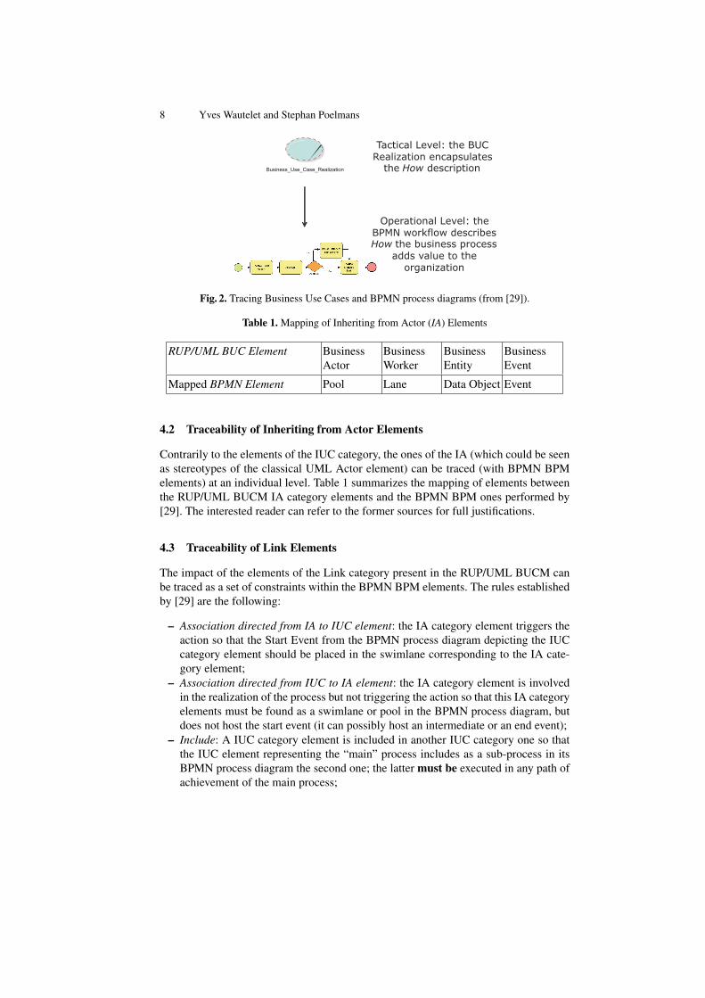
The elements from the IUC category (which could be seen as stereotypes of the clas-sical UML use-case element) are coarse grained (so very abstract) ones. It means thateach elements of this category encapsulate an entire (business) process so are not suitedfor traceability at individual level with elements grouped in the categories of the BPMNBPM. [29] indicates to map a Business Use Case Realization (BUC Realization) ele-ment with one BPMN Process Model. Following the RUP knowledge base, a BusinessUse Case (instance) is a sequence of actions that a business performs that yields an ob-servable result of value to a particular business actor. The BUC Realization representsan entire business process and [29] thus suggests to encapsulate the details of its real-ization within a BPMN process diagram; this is represented in Figure 2. This two-levelabstraction view is fully supported by Visual Paradigm (see for example [28]).
8 Yves Wautelet and Stephan Poelmans
Business_Use_Case_Realization
Tactical Level: the BUCRealization encapsulates
the How description
Operational Level: theBPMN workflow describesHow the business process
adds value to theorganization
Fig. 2. Tracing Business Use Cases and BPMN process diagrams (from [29]).
Table 1. Mapping of Inheriting from Actor (IA) Elements
RUP/UML BUC Element BusinessActor
BusinessWorker
BusinessEntity
BusinessEvent
Mapped BPMN Element Pool Lane Data Object Event
4.2 Traceability of Inheriting from Actor Elements
Contrarily to the elements of the IUC category, the ones of the IA (which could be seenas stereotypes of the classical UML Actor element) can be traced (with BPMN BPMelements) at an individual level. Table 1 summarizes the mapping of elements betweenthe RUP/UML BUCM IA category elements and the BPMN BPM ones performed by[29]. The interested reader can refer to the former sources for full justifications.
4.3 Traceability of Link Elements
The impact of the elements of the Link category present in the RUP/UML BUCM canbe traced as a set of constraints within the BPMN BPM elements. The rules establishedby [29] are the following:
– Association directed from IA to IUC element: the IA category element triggers theaction so that the Start Event from the BPMN process diagram depicting the IUCcategory element should be placed in the swimlane corresponding to the IA cate-gory element;
– Association directed from IUC to IA element: the IA category element is involvedin the realization of the process but not triggering the action so that this IA categoryelements must be found as a swimlane or pool in the BPMN process diagram, butdoes not host the start event (it can possibly host an intermediate or an end event);
– Include: A IUC category element is included in another IUC category one so thatthe IUC element representing the “main” process includes as a sub-process in itsBPMN process diagram the second one; the latter must be executed in any path ofachievement of the main process;

Integrated Enterprise Modeling using the RUP/UML BCM and BPMN 9
– Extend: A IUC category element is thus extended by another IUC category one sothat the IUC element representing the “main” process includes as a sub-process inits BPMN process diagram the second one; the latter may be executed in the pathof achievement of the main process but not necessarily.
– Generalization: A generalization can take place both between elements of IA cate-gory or the IUC one in the RUP/UML BUCM.• When there is a generalization between 2 elements of the IA category, it cannot
be traced at the level of the BPMN process diagram;• When there is a generalization between two elements of the IUC category and
the parent is abstract, only a BPMN process diagram is build for the realiza-tion of the child IUC category element. If it is not abstract, a BPMN processdiagram is also associated with the parent IUC category element.
5 Three Layered Approach for Business Modeling
This section integrates the findings of [29] and suggests a way to integrate the strategic,tactical and operational levels in a unified framework based on the RUP/UML BUCMand the BPMN BPM. The findings of the mapping/alignment study are finally presentedand summarized through a meta-model in the form of a class diagram in Figure 3 andillustrated on a case study. The case study takes place in the chocolate industry.
My Chocolate Factory4 (MCF) is a company producing and selling chocolates thathas commercial presence in 3 continents and manufacturing activity in 2 of them. Thefocus of growth of MCF is the Asian region, and its main competitive advantage is thevertical integration with providers and customers, developing quality through all theproduction stages. In order to support this, MCF requires a system able to integratethe most important activities, in a non-redundant, stable and user-friendly way. Thecompany of Thailand is the scope and the first phase of the new system implementationbecause it covers both manufacturing and sales process, and is the center of operationsin the actual market of Asia. Part of this case is presented in this in Figure 4; The goalof the Section is to give a perspective on the use of the integrated framework and not toillustrate each cases of tactical/operational traceability. It depicts a reinterpretation ofthe strategic aspects of the RUP/UML BUCM – because that perspective is not formallydefined and illustrated in literature5 – as well as the integration of the strategic, tacticaland operational levels on one case.
5.1 Strategic Modeling: the Business Goal Model
The Strategic Level is concerned with decisions including the general direction i.e.long term goals, philosophies and values. In a SE perspective, we would be willing to
4 For confidentiality reasons the name of the company has been changed.5 The effective use in real-life of the strategic elements of the RUP/UML BUCM is hard to
evaluate. Often, this level is neglected or modeled with documents in natural language. Werecognize that strategic modeling using only business goals and objectives does not lead toan exhaustive strategy description. However, this (limited) graphical representation has manybenefits in terms of communication; textual documents can be used in parallel.

10 Yves Wautelet and Stephan Poelmans
Business_Actor
Association_Link
Business_Worker
Data_object
Start_Event
Intermediate_Event
SubprocessLane
<<instantiate>>
ActivityArtifact
Pool
<<instantiate>>
Event
supports_BG_Dependency_Link
Refines_BG_Dependency_Link
Extend_Dependency_Link
Use_Case_Model_Triggering_Element
Refines_BO_Dependency_Link
<<instantiate>>
Include_Dependency_Link
<<instantiate>>
BUCReal_Dependency_Link
Business_Entity
<<instantiate>>
Business_Use_Case_Realization
dimension : String = HOW
0..n
1..n
0..n
1..n
triggers
0..n
1..n
Business_Event
<<instantiate>>
0..n
1..n
uses includes
0..n
1..n
0..n
1..n
Business_Use_Case
dimension : String = WHAT
1 11 1
Business_Goal
metric : Double
refines
0..n
0..n
0..n
0..n
supports
Business_Objective
0..n
1..n
0..n
refines
1..n
Fig. 3. Unified Business Modeling Framework: Meta Model.
represent the goals of the organization as well as the processes it is involved in but in acoarse-grained, non-sequential and non-prioritized manner in order to trace support.
The RUP knowledge base defines a business goal as a requirement that the businessmust satisfy. It argues that business goals describe the desired value of a particularmeasure at some future point in time and can therefore be used to plan and managethe activities of the business. It also distinguishes business objectives as high-level busi-ness goals and emphasizes that because business objectives are usually abstract, theyare difficult to measure and are therefore translated into more measurable lower-levelbusiness goals. Both elements are represented with the same icon.
Business Goals in the large sense (including business objectives) are very interestingin the context of modeling a software system since they allow to include a representa-tion of the business strategy. Indeed, [11] highlights that the purpose of business goalsis to translate the business strategy into measurable steps with which the business oper-ations can be steered in the right direction, and, if necessary, improved. In that context,both concepts of business goals and objectives are interesting, they are mainly distin-guishable by the fact that the first one can be directly associated with a metric while thesecond needs to be refined in more business goals for measurement. Business goals canthen be supported by BUC themselves realized through BUC Realizations allowing todraw a full and clear hierarchy. This will be further discussed into Section 5.1.
The RUP knowledge base defines a business goal as a requirement that the businessmust satisfy. It argues that business goals describe the desired value of a particularmeasure at some future point in time and can therefore be used to plan and managethe activities of the business. It also distinguishes business objectives as high-level busi-ness goals and emphasizes that because business objectives are usually abstract, they

Integrated Enterprise Modeling using the RUP/UML BCM and BPMN 11
are difficult to measure and are therefore translated into more measurable lower-levelbusiness goals. Both elements are represented with the same icon.
Business goals and objectives are very interesting for enterprise modeling sincethey allow representing the business strategy. Indeed, [11] highlights that the purposeof business goals is to translate the business strategy into measurable steps with whichthe business operations can be steered in the right direction, and, if necessary, im-proved. These two elements are mainly distinguishable by the fact that the first one canbe directly associated with a metric while the second needs to be refined in more busi-ness goals for measurement. Business goals can then be supported by BUC themselvesrealized through BUC Realizations allowing to draw a full and clear hierarchy.
Few sources and examples are available to depict how they can/should be used ina project. In [11], the business objectives and goals are decomposed in a tree structureand, within the RUP/UML BUCM, business use cases trace their support of lowest levelgoals only. To clearly highlight the strategic level, we point to the use of an independentmodel (that we simply call the business goal model) at strategic level only relating thebusiness objectives, goals and their refinement as well as the business use-cases sup-porting these goals6; no actor should be present in it (actors will be later documentedat tactical level). RUP/UML business goals are related using a Dependency relationship(arrow) originating on the highest level goal and pointing to the lower level one. Simi-larly, when a RUP/UML business use-cases supports a business goal it is linked usinga Dependency relationship stereotyped supports from the the former to the later.
The upper left part of Figure 3 (the transparent classes) concerns the RUP/UMLBusiness Goal Model. The latter is composed of the Business Objective, the Busi-ness Goal and the Business Use Case classes. Instances of the Business Goal class (soBusiness Goal elements) can be linked through a Refine Dependency Link. Similarly,different instances of the Business Goal class (thus different Business Goal elements)can be linked through a Refine Dependency Link. Instances of the Business Use Caseclass (so Business Use Case elements) support the Business Goal class by offering sup-port so through a Supports Dependency Link.
The strategic layer in Figure 4 illustrates the Goal Model. The business objectiveSustainable Growth is refined in another business objective (Increase Customer Loy-alty) and more business goals. Also, business use-cases support the realization of cer-tain goals, we can notably cite the goal Manage Procurement that, within its realization,can favor the performance of the goal Acquire Raw Material Locally.
5.2 Tactical Modeling: the Business Use-Case Model
The upper middle and left part of Figure 3 (the mid-dark classes) concerns the Busi-ness Use Case Model. The latter is composed of the Business Use Case Realization,the Business Actor, Business Worker, Business Entity, Business Event, the Include Dependency Linkand the Extend Dependency Link classes. Business Use Case Realization elements areinstantiated and correspond to the Business Use Case elements depicted in the goal
6 We emphasize that BUC are thus represented to trace the support of the strategic level while –as will be seen later – BUC realizations are represented at tactical level.
12 Yves Wautelet and Stephan Poelmans
model in a 1 to 1 fashion. These Business Use Case Realization elements are triggeredby Business Worker or Business Actor elements.
The tactical layer of Figure 4 is illustrated by a business use-case diagram. EachBUC Realization in the diagram (i) corresponds to a BUC distinguished at strategiclevel that prescribes what should be done to obtain value (and thus linked with theBusiness Goals and Objectives) and (ii) encapsulates a description in the form of aBPMN process diagram of the process realization scenarios. Traceability between thestrategic and the tactical layers is thus ensured through the mapping of BUC and BUCrealizations.
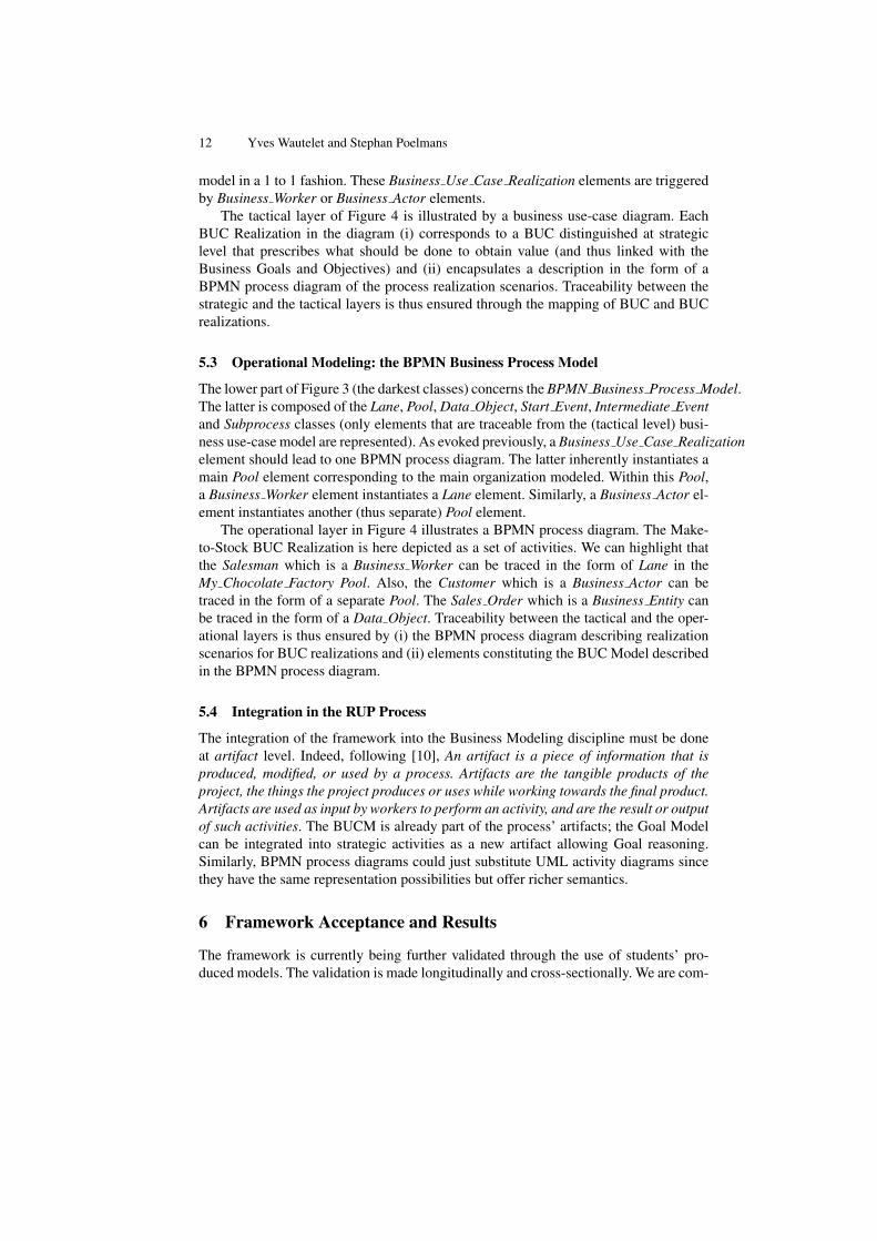
5.3 Operational Modeling: the BPMN Business Process Model
The lower part of Figure 3 (the darkest classes) concerns the BPMN Business Process Model.The latter is composed of the Lane, Pool, Data Object, Start Event, Intermediate Eventand Subprocess classes (only elements that are traceable from the (tactical level) busi-ness use-case model are represented). As evoked previously, a Business Use Case Realizationelement should lead to one BPMN process diagram. The latter inherently instantiates amain Pool element corresponding to the main organization modeled. Within this Pool,a Business Worker element instantiates a Lane element. Similarly, a Business Actor el-ement instantiates another (thus separate) Pool element.
The operational layer in Figure 4 illustrates a BPMN process diagram. The Make-to-Stock BUC Realization is here depicted as a set of activities. We can highlight thatthe Salesman which is a Business Worker can be traced in the form of Lane in theMy Chocolate Factory Pool. Also, the Customer which is a Business Actor can betraced in the form of a separate Pool. The Sales Order which is a Business Entity canbe traced in the form of a Data Object. Traceability between the tactical and the oper-ational layers is thus ensured by (i) the BPMN process diagram describing realizationscenarios for BUC realizations and (ii) elements constituting the BUC Model describedin the BPMN process diagram.
5.4 Integration in the RUP Process
The integration of the framework into the Business Modeling discipline must be doneat artifact level. Indeed, following [10], An artifact is a piece of information that isproduced, modified, or used by a process. Artifacts are the tangible products of theproject, the things the project produces or uses while working towards the final product.Artifacts are used as input by workers to perform an activity, and are the result or outputof such activities. The BUCM is already part of the process’ artifacts; the Goal Modelcan be integrated into strategic activities as a new artifact allowing Goal reasoning.Similarly, BPMN process diagrams could just substitute UML activity diagrams sincethey have the same representation possibilities but offer richer semantics.
6 Framework Acceptance and Results
The framework is currently being further validated through the use of students’ pro-duced models. The validation is made longitudinally and cross-sectionally. We are com-

Integrated Enterprise Modeling using the RUP/UML BCM and BPMN 13
Sales_Representative
Manage Pre_Sales
Manage_Procurement
Sourcer
Sales_Order
Make_to_order
Salesman
Customer
Make_to_stock
Realize Regional DeliveryMeet the Local Market Tastes Acquire Raw Material Locally
Increase Customer Loyalty Reduce Costs Reduce Carbon Impact
Sustainable Growth
Expand in Asian Market
Increase Market Share
Make-to-stock
Reduce Stocks
Make-to-order
<<supports>><<supports>>
<<refines>>
<<refines>> <<refines>>
<<refines>>
<<refines>> <<refines>> <<refines>> <<refines>> <<refines>><<refines>>
Manage Pre-Sales
Manage Procurement
<<supports>>
<<supports>>
<<supports>>
Strategic Level:
Goal Model
Tactical Level:
Business Use Case Model
Operational Level:
BPMN Business Process Diagram
(illustration on the
Make-to-Order process)
Fig. 4. Unified Business Modeling Framework Applied on the Case Study.

14 Yves Wautelet and Stephan Poelmans
paring the work produced by cohorts of students from different generations. Concretelya same case has been modeled by students that have only been taught the basic artifactsfrom the RUP and BPMN and by students that have received a specific training on thestructure and traceability rules. All of the students reports are given a score in functionof the (i) the quality of the application of the structure and traceability (including thecohort not familiar with the framework of this paper), and (ii) on the general qualityand completeness of the models produced. We then compare the results of the 2 cohorts(without and with knowledge of the framework). Across the cohorts, traceability scoresare also correlated to the general scores. The full validation of the framework will bepart of a future communication in the form of a scientific article.
7 Conclusion
The conjunct use of the RUP/UML BUC Model and the BPMN BPM leads to an inte-grated framework that allows to model both the strategic, tactical and operational layersof a business modeling problem. The framework has been used in the context of struc-tured learning of software engineering in a master course on information management.With respect to the traditional RUP approach, the pedagogical approach is enhanced be-cause of the strength of the framework to enforce traceability at all levels thanks to thericher semantics proposed by BPMN’s BPM compared to the classical UML activitymodel. Also, it allows to use the BPMN BPM that is widely adopted in the industry.
The coupling of elements could be made stronger if backed by an empirical evalu-ation of the choices that would be made by practitioners. This particular point will alsobe the subject of a study in the coming months. Future work includes the evaluationof the benefits of framework use in various contexts. Indeed, as evoked, the primarywillingness of its use is pure business modeling so not necessary leading to softwaredevelopment. It can indeed be used to audit business processes in order to point outweaknesses and optimization flows, for modeling the as-is situation in off-the shelfsoftware development (like for integrated ERP systems), etc.
References
1. Chinosi, M., Trombetta, A.: Bpmn: An introduction to the standard. Computer Standards &Interfaces 34(1), 124–134 (2012)
2. Ciancarini, P.: On the education of future software engineers. In: Roman, G.C., Griswold,W.G., Nuseibeh, B. (eds.) ICSE. pp. 649–650. ACM (2005)
3. Cruz, E., Machado, R., Santos, M.: From business process models to use case models: Asystematic approach. In: Aveiro, D., Tribolet, J., Gouveia, D. (eds.) Advances in EnterpriseEngineering VIII, LNBIP, vol. 174, pp. 167–181. Springer International Publishing (2014)
4. Dijkman, R.M., Dumas, M., Ouyang, C.: Semantics and analysis of business process modelsin bpmn. Information & Software Technology 50(12), 1281–1294 (2008)
5. Dumas, M.: Case study : Bpmn to bpel model transformation. In: 5th International Workshopon GraphBased Tools (GraBaTs) (2009)
6. Exposito, E.: ypbl methodology: A problem-based learning method applied to software en-gineering. In: Education Engineering (EDUCON), 2010 IEEE. pp. 1817–1823 (April 2010)

Integrated Enterprise Modeling using the RUP/UML BCM and BPMN 15
7. Friedenstab, J., Janiesch, C., Matzner, M., Muller, O.: Extending BPMN for business activ-ity monitoring. In: 45th Hawaii International International Conference on Systems Science(HICSS-45 2012), Proceedings, 4-7 January 2012, Grand Wailea, Maui, HI, USA. pp. 4158–4167. IEEE Computer Society (2012)
8. Gibbs, R.D.: Project Management with the IBM R©Rational Unified Process R©: LessonsFrom The Trenches. IBM Press (2006)
9. Herden, A., Farias, P.P.M., Albuquerque, A.B.: An Approach Based on BPMN to Detail UseCases, pp. 537–544. Springer International Publishing, Cham (2015)
10. IBM: The Rational Unified Process, Version 7.0.1 (2007)11. Johnston, S.: Rational R©uml profile for business modeling. Tech. rep. (2004)12. Kruchten, P.: The rational unified process : An introduction. Longman (Wokingham),
Addison-Wesley, December (2003)13. Lubke, D., Schneider, K., Weidlich, M.: Visualizing use case sets as bpmn processes. In:
Requirements Engineering Visualization, 2008. REV ’08. pp. 21–25 (Sept 2008)14. zur Muehlen, M., Recker, J.: How much language is enough? theoretical and practical use of
the business process modeling notation. In: Jr., J.A.B., Krogstie, J., Pastor, O., Pernici, B.,Rolland, C., Sølvberg, A. (eds.) Seminal Contributions to Information Systems Engineering,25 Years of CAiSE, pp. 429–443. Springer (2013)
15. Nailburg, E.J., Maksimchuk, R.A.: UML for Database Design. Addison-Wesley LongmanPublishing Co., Inc., Boston, MA, USA, 1st edn. (2001)
16. OMG: Business process model and notation (bpmn). version 2.0.1. Tech. rep. (2013)17. OMG: Omg unified modeling language (omg uml). version 2.5. Tech. rep. (2015)18. Oscar, S.: Visual Paradigm for Uml. International Book Market Service Limited (2013)19. Ouyang, C., Dumas, M., ter Hofstede, A.H.M., van der Aalst, W.M.P.: From BPMN process
models to BPEL web services. In: 2006 IEEE ICWS 2006, , Chicago, Illinois, USA. pp.285–292. IEEE Computer Society (2006)
20. Ouyang, C., Dumas, M., Hofstede, A.H.M.T., et al.: From business process models toprocess-oriented software systems: The bpmn to bpel way (2006)
21. Ouyang, C., Dumas, M., ter Hofstede, A.H., van der Aalst, W.M.: Pattern-based translation ofbpmn process models to bpel web services. International Journal of Web Services Research(JWSR) 5(1), 42–62 (2007)
22. Paradigm, V.: From business process to use case. https://www.visual-paradigm.com/tutorials/from-business-process-to-use-cases.jsp
23. Quatrani, T., Palistrant, J.: Visual Modeling with IBM Rational Software Architect and UML(The developerWorks Series). IBM Press (2006)
24. Shishkov, B., Xie, Z., Liu, K., Dietz, J.: Deriving use case from business process modelsdeveloped using norm analysis. In: Gazendam, H., Jorna, R., Cijsouw, R. (eds.) Dynamicsand Change in Organizations, pp. 117–131. Springer Netherlands (2003)
25. Shuja, A., Krebs, J.: Ibm R©; rational unified process R©; reference and certification guide:solution designer. IBM Press, first edn. (2007)
26. Stephen A. White, Derek Miers: BPMN Modeling and Reference Guide. Future StrategiesInc., Lighthouse Pt, FL (2008)
27. Van Lamsweerde, A.: Requirements engineering: From System Goals to UML Models toSoftware Specifications. Wiley (2009)
28. VisualParadigm: From use case to business process (2012), https://www.youtube.com/watch?v=jkIZuBZ876c
29. Wautelet, Y., Poelmans, S.: Aligning the elements of the RUP/UML business use-case modeland the BPMN business process diagram. In: Grunbacher, P., Perini, A. (eds.) RequirementsEngineering: Foundation for Software Quality - 23rd International Working Conference,REFSQ 2017, Essen, Germany, Proceedings. LNCS, vol. 10153, pp. 22–30. Springer (2017)
30. Yu, E., Giorgini, P., Maiden, N., Mylopoulos, J.: Social Modeling for Requirements Engi-neering. MIT Press (2011)