Embed Size (px)
Citation preview

An Integrated Approach to Cyber-Enabled Additive Manufacturing using Physics based,
Coupled Multi-scale Process Modeling
Deepankar Pal, Nachiket Patil, Mohammad Nikoukar, Kai Zeng, Khalid Haludeen Kutty and
Brent E. Stucker
Department of Industrial Engineering, University of Louisville
Abstract
The complexity of localized and dynamic boundary conditions in additive manufacturing
processes makes it difficult to track in-situ thermo-mechanical changes at different length scales
within a part using experimental equipment such as a FLIR1 system and other NDE2 techniques.
Moreover, in-situ process monitoring is limited to providing information at an exposed surface of
the build. As a result, an understanding of the bulk microstructure and behavior of a part still
requires rigorous post-process microscopy and mechanical testing.
In order to circumvent the limited feedback obtained from in-situ experiments and to better
understand material response, a novel 3D dislocation density based thermo-mechanical finite
element framework has been developed. This framework solves for the in-situ response 2 orders
of magnitude faster than currently used state-of-the-art modeling software since it has been
specifically designed for additive manufacturing platforms. Various aspects of this simulation tool
have been and are being validated using research grants from NSF3, ONR4, AFRL5, NIST6 and
NAMII7.
This modeling activity has many potential commercial impacts, such as to predict the
anisotropic performance of AM-produced components before they are built and as a method to
enable in-situ closed-loop process control by monitoring the process and comparing it to predicted
responses in real time (as the model will be used to predict results faster than an AM machine can
build a part). This manuscript provides an overview of various software modules essential for
creation of a robust and reliable AM software suite to address future needs for machine
development, material (alloy) development and geometric optimization.
Introduction
Additive Manufacturing (AM) is a way of converting a virtual 3 Dimensional file into a
useful physical 3 Dimensional object using energy sources such as light, ultrasonic vibration, lasers
or electron beams to bond or otherwise join materials. Depending on the technology and the
material(s) used for creation of the final part, the strength and type of these bonds vary. Evaluation
of these bonds as a function of process parameters and materials is a critical step for process
reliability and quality control.
In AM, the 2 dimensional layer-by-layer addition of materials to fabricate the final
geometry enables complex internal features such as channels and embedment of pre-fabricated
1 FLIR= Forward Looking Infra-Red camera 2 NDE=Non Destructive Engineering 3 NSF=National Science Foundation 4 ONR=Office of Naval Research 5 AFRL=Air Force Research Laboratory 6 NIST=National Institute of Standards and Technology 7 NAMII=National Additive Manufacturing Innovation Institute
1

components such as fibers and sensors. The inclusion of these internal features and the highly
dynamic nature of these processes lead to residual stresses and dimensional warping which may
lead to runtime (during the build) or premature failure of these parts in service. This calls for
evaluation of residual stresses and dimensional warping of the parts as a function of process
parameters, materials and build geometry. In addition, the surface finish and geometrical accuracy
of AM-produced parts are not necessarily good enough for precision applications and thus post-
processing operations are often required. Therefore, evaluation of surface finish and geometrical
accuracy as a function of 2 Dimensional slice information, part orientation, material and process
characteristics is also important.
To fully capitalize on the future potential for AM for precision engineered components, a
theoretical understanding of the physics involved in AM processing and validated software tools
which can predict process effects are needed. These software tools will enable future machines to
be more efficient, scientists and researchers to develop new material alloys specifically tweaked
for cooling rates experienced during additive manufacturing and designers to more fully explore
the geometric freedom and functionality desired by the end-user while still maintaining essential
strength, fatigue, corrosion or other attributes.
Broader Objectives
The objective of this modeling effort is to build new software tools which can efficiently
simulate highly dynamic, coupled manufacturing and metallurgical processes, including the high
strain and cooling rates exhibited by additive manufacturing. Some of the key objectives of this
effort are:
a) To formulate process map response surfaces which correlate parameters and outcomes such
as beam power and scan speed to grain size and shapes or melt pool geometry. This enables
optimization of materials and geometry apriori. Other predictive outputs can include residual
stress, dynamic warping and mechanical properties.
b) To enable closed loop control where on-the-fly compensation for out-of-spec thermal or
microstructural defects can be achieved. A possible path for doing so includes using optical
sensors which record layer-by-layer information such as temperatures, geometry, distortion,
porosity, etc. and their spatio-temporal locations so that this information can be fed for an
instantaneous next layer feed forward simulation using the real, current build geometry so that
a local tweak of the process parameters can be achieved in the x-y vicinity of the defect in the
previous layer to counter-act or fix the defect. With the increasing speed of simulations
achievable by porting codes to a General Purpose Graphical Processing Unit (GP-GPU), these
defects may even be fixable within a layer by changing, for instance, beam power and scan
speed in the next scan vector.
c) To accurately predict mechanical properties of the parts as a function of process
parameters, material(s) and geometry.
d) To formulate better scan strategies and optimize support structure placement for metal
melting based AM, leading to lower residual stresses and less post-processing of the fabricated
part.
2

Software capabilities
Finite Element Analysis software suites generally have three components built into them,
namely preprocessing, solver and post-processing capabilities. In this paper, we will focus on the
preprocessing and solver capabilities of our software. It should be noted that all of these
capabilities were written as Fortran and/or Matlab routines and can run independently from
commercial FEA software tools.
3 Dimensional multi-scale dynamic meshing capabilities (Preprocessing)
Novel dynamically adaptive meshing strategies have been formulated which can move with
the energy sources and sinks employed in additive manufacturing technologies. The adaptive
meshes are generally refined near the energy source or energy dispersive mechanism(s), since high
thermal or stress/strain gradients in these locations require fine-scale accuracy to minimize the
global error which would occur if the spatial discretization remained at a coarser scale. The
required refinement regimes are multi-dimensional in nature. Some examples of energy sources
include Gaussian point energy sources (figure1) for Selective laser Melting (SLM) and Electron
Beam Melting (EBM) and line energy ultrasonic vibration compressive forces (figure2a) for
Ultrasonic Consolidation (UC). An example of superficial or area based refinement occurs at the
interface of mating surfaces of foils (figure 2b) undergoing ultrasonic consolidation (UC) or
friction stir welding. An example of volume based refinements include the modeling of Inconel
alloys, since they contain secondary and tertiary precipitates (figure 3) which respond differently
than the bulk to the thermal and deformation fields experienced in metal based AM processes such
as UC, SLM and EBM. Figure 4 demonstrates a microstructurally informed hexagonal mesh for
predicting the mechanical properties of Ti6/4 parts produced by Electron Beam melting.
Figure1: Meshing configuration for a point energy source located within the fine mesh region. The
point source could be a Gaussian heat source such as a concentrated laser or electron beam and the
fine mesh region moves as the point energy source moves [1].
Zoomed-in view
3

(a)
(b)
Figure 2. Multi-scale mesh for ultrasonic consolidation showing: (a) the full 3D mesh with
selective adaptive refinement near the sonotrode and the interfacial mating surfaces and (b) a close-
up showing how the hexahedral elements are preserved throughout refinement. Red and blue
denote the top and bottom foils respectively. The vertical refined region moves with sonotrode
motion while the horizontal fine mesh region is indexed up layer-by-layer as new foils are added
[2].
4

Figure 3: (1/8th views) (a) Volumetric refined mesh of a precipitate with curvature, (b)
Precipitate+Matrix, (c) 2 D view of the precipitate within the matrix, and (d) full mesh [3].
5

(a) (b)
(c)
Figure 4: (a) Optical micrograph of an EBM-made Ti 6/4 microstructure showing hexagonal prior
β grain motifs and (b) microstructurally informed mesh and (c) In-plane mesh complexity [4].
-3 -2 -1 0 1 2 3 4
x 10-4
0
1
2
3
4
5
6x 10
-4
6

Thermo-Mechanical Finite Element Framework including macroscopic non-linear thermal and
deformation behavior of materials
A general-purpose non-linear coupled thermo-mechanical solver has been developed. Selective
Laser Melting (SLM) thermal contours (figure 5) and residual stresses on a block of 4 mm×4 mm
at the third processed layer (figure 6) are shown based upon the developed solution methodology
for a part built directly on the base plate. Experiments to validate the residual stress predictions
will be performed in the future using Neutron Beam energy sources.
(a) (b)
Figure 5: Match of thermal contours between non-linear Thermo-mechanical analysis (a)
(Temperature in Kelvins) using the mesh provided in Figure 1 and experiments (b) obtained using
a Forward Looking InfraRed (FLIR) camera (Temperature in Celsius) [1]. This model runs atleast
66 times faster than its ANSYS counterpart [5].
Figure 6. Residual stress contours on a previously deposited layer at the same location as the
applied energy shown in figure 5 (a).
7

Dislocation Density based Finite Element Method (DDCPFEM) [2-4,6-10]
The UC problem (figure 2) as a function of normal force, weld speed and surface roughness has
been modeled using DDCPFEM. The model has been shown to accurately predict average grain
size at the interface. Figure 7 illustrates the ability of the model to predict trends for surface-finish-
based differences in subgrain refinement at the interface.
.
Figure 7: Variation of GND with surface roughness. The simulated average grain size at the mating
interface for the rough sample was ~1.3 µm whereas the experimentally obtained and weight
averaged value was found to be ~1.33 µm. The simulated average grain size at the mating interface
for the smooth sample was ~2.43 µm which is in good agreement with Dr. K. Johnson’s PhD work
[10].
The effect of microstructure (figure 4) on mechanical properties can also been predicted using
DDCPFEM. The analysis provides both global scale and local scales results. Results in Figures 8
and 9 illustrate detailed stress/strain analysis using DDCPFEM in regimes where commercial
software packages fail to accurately predict the grain specific response for plastic deformation.
8

Figure 8: Volume averaged true stress-strain plot for a vertically-built EBM Ti6/4 sample
computed by ANSYS (orange) and DDCPFEM (red). These average stress-strain evolutions have
been compared against experiments (blue) [4].
(a) (b)
Figure 9: Plastic strain distribution at 10% total average strain for the stress/strain curves from
Figure 8: (a) DDCPFEM simulations and (b) ANSYS anisotropic multilinear continuum plasticity
model. The plastic strain evolution in DDCPFEM simulations is grain-orientation specific in (a)
whereas the plastic strain is symmetric about the top and bottom centers of the simulated model in
(b) which is physically incorrect. The value of the maximum plastic strain at the top center is
~17.88% in both the ANSYS and DDCPFEM simulations [4].
Eigenmodal solver (EigenSolver) [11]
A unique methodology is under development to more quickly solve the thermo-mechanical SLM
process problem. All SLM process models are computationally expensive to solve using traditional
9

FEM methods, as they require fine-scale resolution across a part volume that is many orders of
magnitude larger than the fine-scale lengths. This has led to efforts to solve the problem using
asymptotic behaviors, modal space methodologies or beam theories. The intent behind this solver
is to solve for dominant modes in the macroscopic domain and local high frequency modes in the
microscopic domain using our thermo-mechanical solver. These can be accurately applied at
certain locations (e.g. 5 layers) below the melt pool.
Beam and plate theories are meant to take benefit of asymptotic theories involved in dimensionally
reducible structures. Beam theories for complicated geometries such as aircraft wings, naval
structures (ship hulls) etc. and material variations across the cross-section and length have been a
topic of research in the past. An analytical method, namely the Variational Asymptotic Method
(VAM), has been used extensively to derive these beam theories. One of the limitations of this
methodology lies in the difficulty of deriving beam theories for very complicated beams. We have
developed a new beam theory derivation methodology EigenSolver using a Finite Element
Method. This novel method can consider any complicated shape and cross-sectional variation and
derives beam or plate theories involved in it. Further it has applications in problems which do not
fall in the categories of beams or plates (e.g. prismatic bodies or any general structural
configuration). The importance of this methodology lies in calculating eigenvectors of the cross-
section or group of nodes in FEM matrices such as the stiffness matrix. It is well known that
eigenvalues and eigenvectors are computationally expensive to calculate. To overcome this
difficulty, any set of orthogonal vectors can be employed for this purpose and their coupling is
calculated to derive simplified simultaneous equations. Various material and geometrical
nonlinearities can be incorporated in beam theories with the help of our other existing solver tools.
This methodology can be further generalized to work with groups of nodes in banded FEM meshes
for large size problems. These can then be solved on desktop computers. In summary this
methodology should be capable of:
Representing complicated geometry and material inhomogeneity in beams.
Inexpensive computations leading to global-local coupled response.
Generalization to be used for any problem with some hidden unknown asymptotics.
Solving large size FEM problems (for example 10 million Degrees of Freedom or much
larger in some specific cases) on desktop computers.
Simplified and fast FEM matrices assembly.
In addition, an analytical method using a multi-dimensional multi-resolution wavelet based
eigentheory is also being developed. This methodology can solve both linear and non-linear
problems provided a space transformation between the cross-sections is available. The theory is
being extended to account for inhomogenous material distributions which are very common among
powder based additive manufacturing technologies where solid and powder continuously interact
in a non-linear mode with the applied thermal and resulting deformation based boundary
conditions.
10
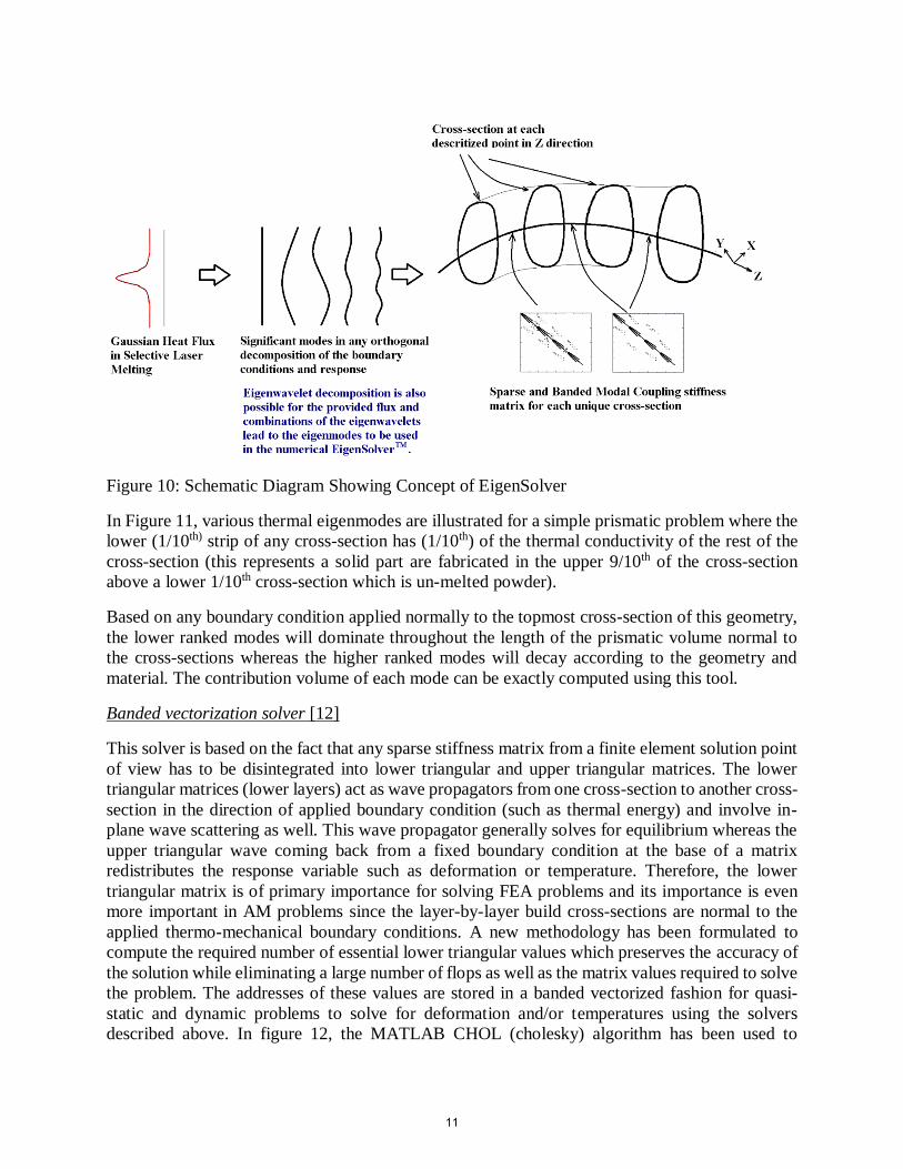
Figure 10: Schematic Diagram Showing Concept of EigenSolver
In Figure 11, various thermal eigenmodes are illustrated for a simple prismatic problem where the
lower (1/10th) strip of any cross-section has (1/10th) of the thermal conductivity of the rest of the
cross-section (this represents a solid part are fabricated in the upper 9/10th of the cross-section
above a lower 1/10th cross-section which is un-melted powder).
Based on any boundary condition applied normally to the topmost cross-section of this geometry,
the lower ranked modes will dominate throughout the length of the prismatic volume normal to
the cross-sections whereas the higher ranked modes will decay according to the geometry and
material. The contribution volume of each mode can be exactly computed using this tool.
Banded vectorization solver [12]
This solver is based on the fact that any sparse stiffness matrix from a finite element solution point
of view has to be disintegrated into lower triangular and upper triangular matrices. The lower
triangular matrices (lower layers) act as wave propagators from one cross-section to another cross-
section in the direction of applied boundary condition (such as thermal energy) and involve in-
plane wave scattering as well. This wave propagator generally solves for equilibrium whereas the
upper triangular wave coming back from a fixed boundary condition at the base of a matrix
redistributes the response variable such as deformation or temperature. Therefore, the lower
triangular matrix is of primary importance for solving FEA problems and its importance is even
more important in AM problems since the layer-by-layer build cross-sections are normal to the
applied thermo-mechanical boundary conditions. A new methodology has been formulated to
compute the required number of essential lower triangular values which preserves the accuracy of
the solution while eliminating a large number of flops as well as the matrix values required to solve
the problem. The addresses of these values are stored in a banded vectorized fashion for quasi-
static and dynamic problems to solve for deformation and/or temperatures using the solvers
described above. In figure 12, the MATLAB CHOL (cholesky) algorithm has been used to
11

compute the lower triangular matrix of a thermal stiffness matrix of a 3 Dimensional prismatic
(cuboid) thermal problem with a Gaussian flux applied on its top surface, the base of the domain
has been kept at a specified temperature of 353 K with opposing faces perpendicular to x and y
directions comprising of periodic boundary conditions. The periodic boundary conditions involves
constraints which tremendously affect the bandwidth of the thermal stiffness matrix and therefore
the lower triangular matrix in Figure 12 is highly populated. On performing banded vectorization
using L(row number1,:) *L(row number2,:) capping for calculation of updated L(row number1, :)
with increasing thresholds and checking the resulting changes in quality of the solution vector in
terms of error w.r.t original solution using 1st and 2nd norms of the difference vector, it has been
found that the solution vector has not changed beyond 0.026% while the number of the values
required to compute the lower triangular matrix has decreased to 6.7% than required by the
MATLAB CHOL algorithm. The optimized matrix at 10-4 has been shown in figure 13. In figure
14, the number of flops have been calculated with respect to logarithm of L*LT capping threshold.
It has been found that for the matrix represented in Figure 13 the number of flops required to
calculate that matrix is around 1.57% of the flops required for calculating the lower triangular
matrix by Cholesky algorithm. Also, the efficiency and speed statistics of the modified Cholesky
method has been completely tracked for solution and flops as a function of discrete values of
logarithm of L*LT capping threshold.
12

Figure 11: 1st to 8th significant modes for of the powder bed case study c/s
Figure 12: Matlab generated lower triangular matrix for a sample thermal problem with periodic
boundary conditions.
13

Figure 13: Preserved solution optimized lower triangular matrix by modified CHOL (Cholesky
factorization) method. Only 6.7% of the values were required to efficiently solve the problem with
solution quality preservation.
Figure 14: Efficiency and speed statistics for modified CHOL method.
Enhanced Contact solver [13]
A matrix based self-updating solver has also been created to solve for adhesion/delamination and
crack growth problems relevant to solid state metal additive manufacturing, support snapping in
melting based metal additive manufacturing and fatigue crack propagation in additively
14

manufactured parts. A simple problem has been solved to illustrate the feasibility of this method
using linear elastic blocks of Stainless Steel 304 held on top of each other via normal compressive
force and unidirectional simple shear. The blocks have a dimension of 1mm×1mm×500µm (~100
grain diameters in rolled SS 304 sheets in the z direction). The objective is to obtain a macroscopic
shear resistance-shear slip law and use this law at the interface while solving contact FEM
problems using anisotropic plasticity based constitutive laws or DDCPFEM. The shear resistance
as a function of macroscopic slip has been plotted in figure 15 whereas the deformed configuration
(red) and reference configuration (blue) are shown in figure 16. It can be clearly observed that
after a certain number of slip steps, the blocks lose their resistance in shear at the interface and the
block on top slides without much difficulty.
Figure 15: Shear resistance as a function of macroscopic slip.
3 Dimensional Surface Reconstruction software [14]
Geometrical errors during 2D slicing and thermo-mechanical deformation during processing are
two sources of inaccuracies in the parts produced using AM technologies. In most AM processes,
the CAD model is represented by the STL file format which is sliced into layers. It has been
assumed that the Delaunay triangulation in an STL file is an accurate representation of the 3D
CAD geometry. The Common Layer Interface (CLI) and SLI files are two common file formats
containing the layer information. We have developed a software program to access the cross
sectional information from the CLI/SLI files and stack the extracted layers to reconstruct the 3D
geometry. The geometrical errors in the prefabrication stage can be obtained by comparing the
STL file against the ‘stacked’ model. The scan strategy including build orientation, scan angle,
hatch space and beam offsets can be also extracted from the ‘stacked’ model. This information is
further used in thermo-mechanical analysis of the SLM process using our framework. The
predicted deformation using this analysis is compared against the actual STL file and the error is
proposed to be used as a corrector for closed loop control of the SLM process.
15

Figure 16: Reference (blue) and deformed (red) configurations during macroscopic slip
Figure 17: Comparison of the original CAD model of a semi sphere with the stacked model. (a)
Solid CAD model and (b) Stacked model from layers of cross sections with stair-step-effect errors.
The magnitude of the error increases from red to blue.
16

Conclusions
In response to an increasing need for optimization of parameters, materials and geometries
for AM-fabricated parts, an integrated approach to be accurately simulating the physics and
materials science aspects of AM has been undertaken. Since AM is a particularly time and
resource-consuming problem to solve, based upon moving energy sources and material additions
over time and space, new numerical algorithms and software tools must be developed.
Homogenization strategies applied to some of these tools may lead to better machine architectures
in the near future, such as for modeling the multibeam capabilities of electron beam-based and
solid state additive manufacturing. The numerical algorithms and tools are generic for highly
dynamic processes with high strain and thermal gradient environments, and can be flexibly adapted
for relatively quasi-static and macroscopic traditional manufacturing processes as well. The
process of integration of these software tools to result in a fully functional software suite for
additive manufacturing processes is underway.
Acknowledgements
The authors would like to gratefully acknowledge funding support from the Office of Naval
Research (N000141110689 & N000140710633), the Air Force Research Laboratory (as a
subcontractor to Mound Laser & Photonics Center on three SBIR projects), the National Institute
of Standards and Technology (70NANB12H262), the National Additive Manufacturing
Innovation Institute (as a subcontractor to Case Western Reserve University) and the National
Science Foundation (CMMI-1234468).
References
[1] Pal, D., Patil, N., Khalid Rafi, H., Zeng, K., Moreland, A., Hicks, A., Beeler, D. and Stucker,
B.E., 2013, “A fast Feed Forward Dynamic Adaptive Mesh refinement and de-refinement for
applications in non-linear spatiotemporally periodic localized boundary condition, Journal of
Applied Physics (under review).
[2] Pal, D., Patil, N., and Stucker, B.E., 2013, A study of subgrain formation in Al 3003 H-18 foils
undergoing Ultrasonic Additive Manufacturing using a Dislocation Density based Crystal
Plasticity Finite Element Framework,” Journal of Applied Physics, 113(20), pp.203517.1-
203517.8.
[3] Pal, D., Behera, S.K., and Ghosh, S., 2009, “Crystal Plasticity Modeling of Creep and
Microtwinning in Nickel Based Superalloys,” Proceedings of the 10th United States National
Congress on Computational Mechanics, Columbus, OH.
[4] Pal, D., Patil, N., and Stucker, B.E., 2012, “Prediction of mechanical properties of Electron
Beam Melted Ti6Al4V parts using dislocation density based crystal plasticity framework,”
Proceedings of the Solid Freeform Fabrication Symposium, Austin, TX.
[5] Zeng, K., Pal, D., Patil, N., and Stucker, B. E., 2013, “A New Dynamic Mesh Method Applied
to the Simulation of Selective Laser Melting,” Proceedings of the Solid Freeform Fabrication
Symposium, Austin, TX.
[6] Pal, D., and Stucker, B. E., 2012, “Time Homogenization of Al3003 H-18 foils undergoing
metallurgical bonding using Ultrasonic Consolidation,” Proceedings of the Solid Freeform
Fabrication Symposium, Austin, TX.
17

[7] Pal, D., and Stucker, B.E., 2011, “Some Studies on Dislocation Density Based Finite Element
Modeling of Ultrasonic Consolidation,” Proceedings of the 5th International conference on
Virtual and Rapid Prototyping, Leiria, Portugal.
[8] Pal, D., and Stucker, B.E., 2011, “Dislocation Density Based Finite Element Modeling of
Ultrasonic Consolidation,” Proceedings of the Solid Freeform Fabrication Symposium, Austin,
TX. (updated approach included)
[9] Pal, D., and Stucker, B.E., 2010, “Dislocation Density Based Finite Element Modeling of
Ultrasonic Consolidation,” Proceedings of the Solid Freeform Fabrication Symposium, Austin,
TX.
[10] Pal, D., and Stucker, B.E., 2012, “Modeling of Ultrasonic Consolidation using a Dislocation
Density based Finite Element Framework,” Virtual and Physical Prototyping Journal, 7(1), pp.
65-79.
[11] Nikoukar, M., Patil, N., Pal, D., and Stucker, B.E., 2013, “Methods for Enhancing the Speed
of Numerical Calculations for the Prediction of the Mechanical Behavior of Parts Made Using
Additive Manufacturing,” Proceedings of the Solid Freeform Fabrication Symposium, Austin,
TX.
[12] Patil, N., Pal, D., and Stucker, B.E., 2013, “A New Finite Element Solver using Numerical
Eigen Modes for Fast Simulation of Additive Manufacturing Processes,” Proceedings of the
Solid Freeform Fabrication Symposium, Austin, TX.
[13] Patil, N., Pal, D., and Stucker, B.E., 2013, “An energy dissipative constitutive model for
multi-surface interface at weld defect sites in Ultrasonic Consolidation Process,” Proceedings
of the Solid Freeform Fabrication Symposium, Austin, TX.
[14] Zeng, K., Patil, N., Gu, H., Gong, H., Pal, D., Starr, T. and Stucker, B.E., 2013, “Layer by
Layer Validation of Geometrical Accuracy in Additive Manufacturing processes,”
Proceedings of the Solid Freeform Fabrication Symposium, Austin, TX.
18