Embed Size (px)
Citation preview

AN INNOVATIVE PUMPED-STORAGE PROJECT IN AN UNDERGROUND MINE
Ernst ZellerNovember 2017

COPYRIGHT©PÖYRY
AGENDA
NOVEMBER 20172
Pump storage technology
Battery vs. Pump storage technology
Why in Pyhäsalmi Ore Mine?
Pyhäsalmi Project

COPYRIGHT©PÖYRY
PUMP STORAGE TECHNOLOGY
NOVEMBER 20173
Pumped storage facility is made by two water basins, connected by a pressure
pipe, with the water running through a pump-turbine rotating motor-generator
Demand
Pumping
PSP Productionמתח תדר יציבות
Load MW
איזור התועלות הדינמיות
Straightened curve
Pumping
Storing potential energy by pumping the water from the lower basin to an upper
one and using that energy by releasing the water back when required
Upper Reservoir
Lower Reservoir
Turbine mode
Pump mode

COPYRIGHT©PÖYRY
PROVEN MATURE TECHNOLOGY
NOVEMBER 20174
World Energy Council 2015:
” 99% of world’s
operational electricity
storage is in hydropower
(pump storage)”
“PSP is a significantly cheaper energy
storage alternative compares to
batteries, answering all national grid
dynamic benefits needs “
IEC 2016:
COPYRIGHT©PÖYRY
PUMPED STORAGE HYDRO WORLDWIDE
NOVEMBER 20175
COPYRIGHT©PÖYRY
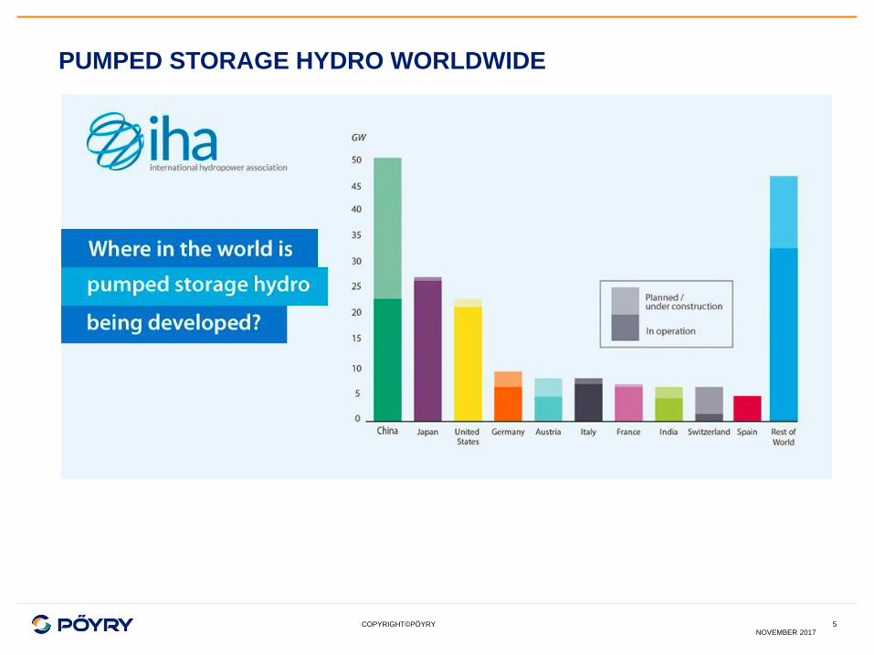
PUMPED STORAGE VS BATTERIES (PSP VS BAT)
NOVEMBER 20176
LIFE TIME TECHNOLOGY
CAPEX OPEX
> 50 years vs. ~15 years
PSP BAT
Batteries Lifetime is 11-15 years*
Batteries storage capacity decreases
substantially after 3 years
* According to NREL Predictive Models of Li-ion Battery Lifetime
1
100
10000
PSP Batteries
O&
M C
ost
[$/kW]
According to Energy Storage Screening Study For Integrating Variable Energy Resources within
the PacifiCorp System July 9, 2014According to EPRI Energy Storage Project A
PSP
~77 %
~68 %
~65 %
~40%
Pumped storage hydro
Batteries Li-ion*
Compressed air
Hydrogen
* Average Efficiency, which declines over the years for Batteries
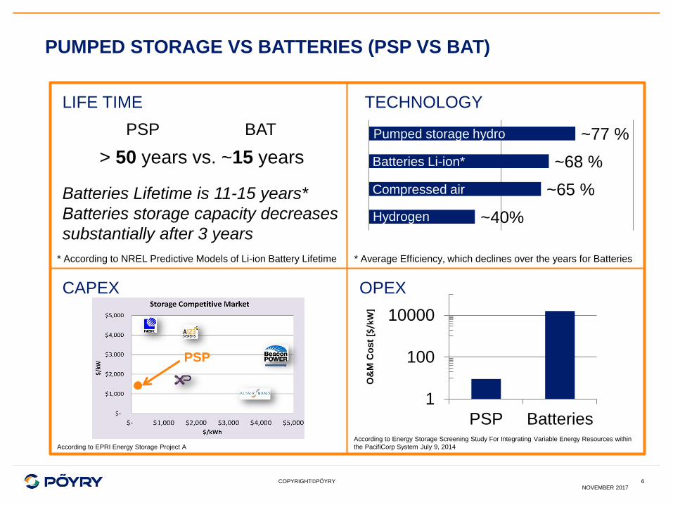
BENEFITS OF PUMPED STORAGE POWER PLANTS
Storing Energy
– Provide a substantial contribution towards a balance between electricity generation and
consumption
– Absorb excess power in the grid particularly when balancing energy produced by wind and
solar plants
– wind and solar erratic through 24 hour period
– Increase of Wind capacity in many emerging countries
– Solar power starts
Balancing Services
– Provide required regulatory functions contributing to grid stabilization and frequency regulation
at primary and secondary levels in generating mode
– Black Start services able
Increasing Effectiveness of Renewables
– Diversify the energy mix
– Absorb base load production particularly from nuclear and coal plants at night and release
during peak hours in morning and evening
Lower the dependency on non-renewable fuels
– Combining the generation of Wind- Solar- and Hydro Energy with Pumped Storage Power
plants
Reducing Transmission costs
– Installing PSPP close to Demand and Generation of Wind Power
7November 2017
COPYRIGHT©PÖYRY
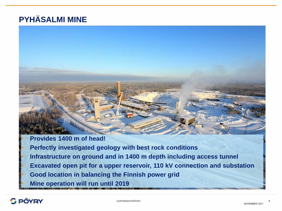
PYHÄSALMI MINE
8NOVEMBER 2017
• Provides 1400 m of head!
• Perfectly investigated geology with best rock conditions
• Infrastructure on ground and in 1400 m depth including access tunnel
• Excavated open pit for a upper reservoir, 110 kV connection and substation
• Good location in balancing the Finnish power grid
• Mine operation will run until 2019
COPYRIGHT©PÖYRY
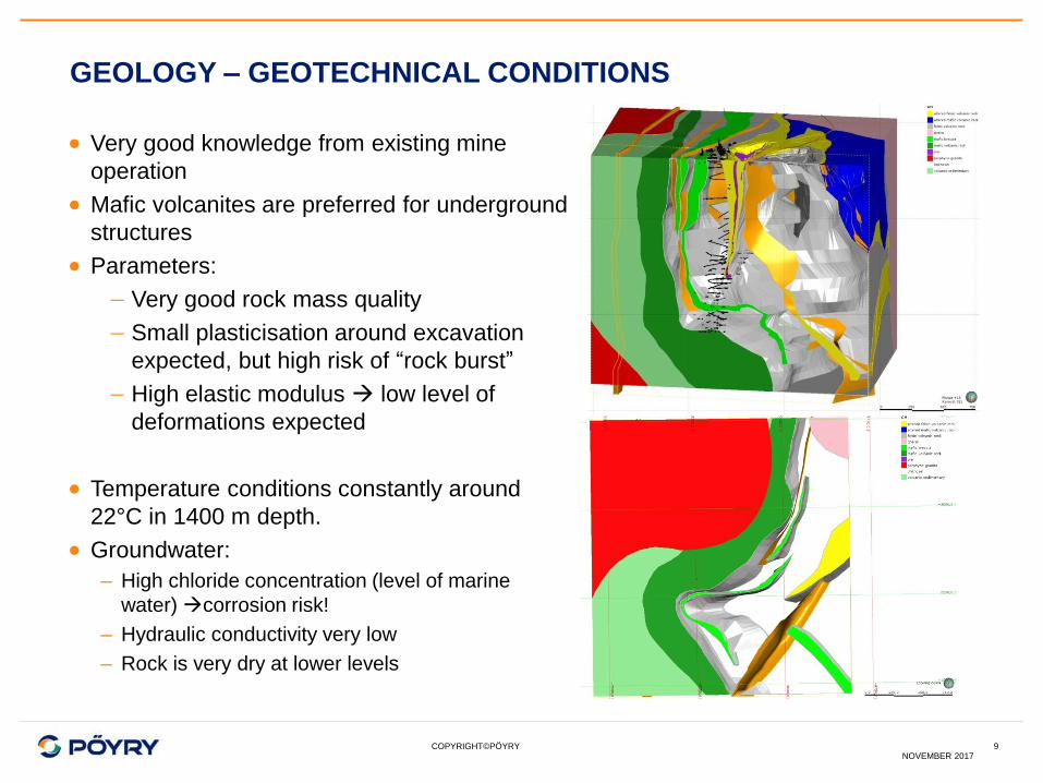
GEOLOGY – GEOTECHNICAL CONDITIONS
Very good knowledge from existing mine
operation
Mafic volcanites are preferred for underground
structures
Parameters:
Very good rock mass quality
Small plasticisation around excavation
expected, but high risk of “rock burst”
High elastic modulus low level of
deformations expected
Temperature conditions constantly around
22°C in 1400 m depth.
Groundwater:
– High chloride concentration (level of marine
water) corrosion risk!
– Hydraulic conductivity very low
– Rock is very dry at lower levels
NOVEMBER 20179

COPYRIGHT©PÖYRY
ALTERNATIVE STUDY – HYDRAULIC HEAD
NOVEMBER 201710
Elevation -700 m
Elevation -1400 m
Preferred location
– Higher head / reduced flow rate
– Reduced underground storage size main cost driver
COPYRIGHT©PÖYRY
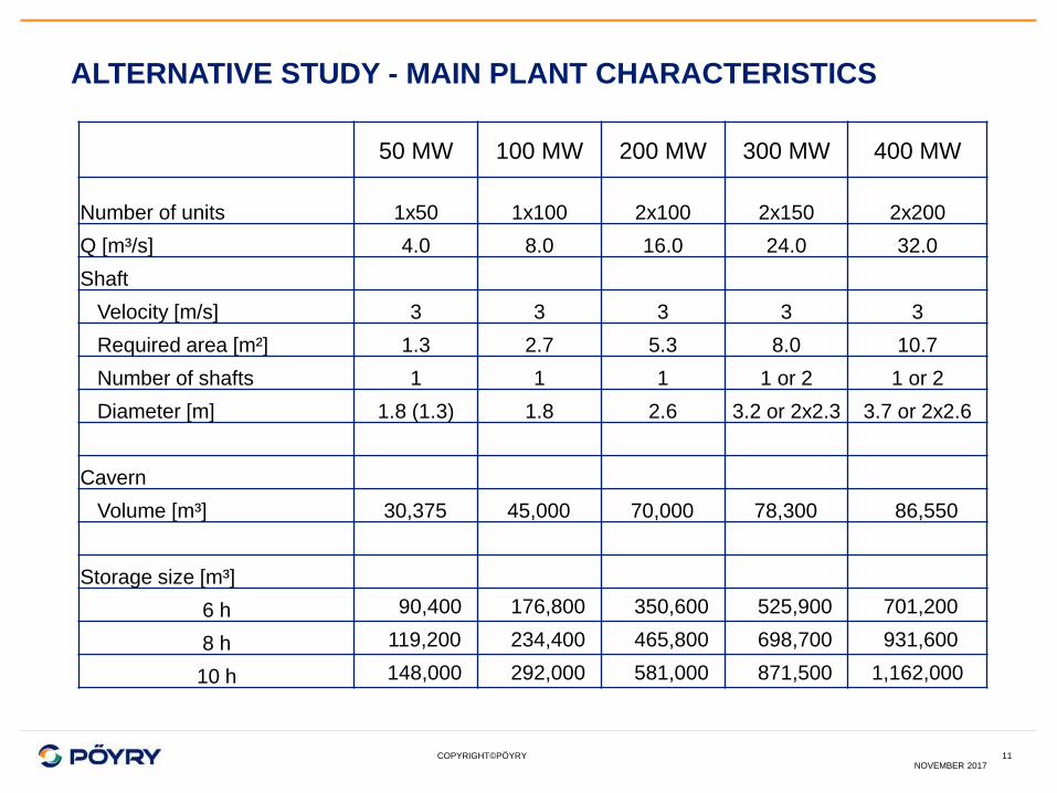
ALTERNATIVE STUDY - MAIN PLANT CHARACTERISTICS
NOVEMBER 201711
50 MW 100 MW 200 MW 300 MW 400 MW
Number of units 1x50 1x100 2x100 2x150 2x200
Q [m³/s] 4.0 8.0 16.0 24.0 32.0
Shaft
Velocity [m/s] 3 3 3 3 3
Required area [m²] 1.3 2.7 5.3 8.0 10.7
Number of shafts 1 1 1 1 or 2 1 or 2
Diameter [m] 1.8 (1.3) 1.8 2.6 3.2 or 2x2.3 3.7 or 2x2.6
Cavern
Volume [m³] 30,375 45,000 70,000 78,300 86,550
Storage size [m³]
6 h 90,400 176,800 350,600 525,900 701,200
8 h 119,200 234,400 465,800 698,700 931,600
10 h 148,000 292,000 581,000 871,500 1,162,000
COPYRIGHT©PÖYRY
INITIAL ECONOMIC EVALUATION
NOVEMBER 201712
Expected revenues from day-ahead market are relative modest
Revenues from ancillary services are limited due to market size
Outcome from generation benefit analysis (Pöyry’s BID3 market model)
suggests that the most feasible configuration is around 75 MW and 6 hours
storage size.
Due to current challenging market conditions an implementation in stages
appears favourable.
2 options have been studied further:
– 75 + 75 MW
– 100 + 100 MW
wide range from 75 MW to 200 MW is covered within the feasibility study
COPYRIGHT©PÖYRY
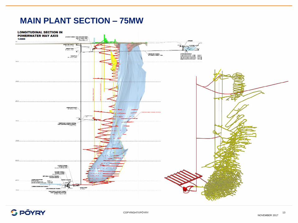
MAIN PLANT SECTION – 75MW
13NOVEMBER 2017

COPYRIGHT©PÖYRY
MAIN PLANT LAYOUT – 75MW
14NOVEMBER 2017

COPYRIGHT©PÖYRY
LOWER RESERVOIR
Layout of final tunnels optimized
in respect to geological
conditions (joint systems, primary
state of stress) and existing
tunnel system
Aeration tunnel can be used for
construction, partly as reservoir
and for later access in case of
maintenance
Active storage of 162,000 m³ and
21,000 m³ for dewatering of
power waterway
15NOVEMBER 2017

COPYRIGHT©PÖYRY
POWER SHAFT - UNLINED
Unlined pressure shaft (based on experience from Norway)
Design criteria:
Sufficient distance to existing tunnels (based on rock
condition / hydraulic gradient < 18 distance min. 70m
Reduced flow velocity < 2.5 m/s
Include a rock trap before cavern
Raised boring method constructed in 2 sections
Treatment of fracture zone
NOVEMBER 201716

COPYRIGHT©PÖYRY
ES PYHÄSALMI - CAVERN DESIGN – 75MW
17NOVEMBER 2017

COPYRIGHT©PÖYRY
PROJECT IMPLEMENTATION - EXPANDABLE DESIGN
18NOVEMBER 2017
COPYRIGHT©PÖYRYNOVEMBER 2017
19
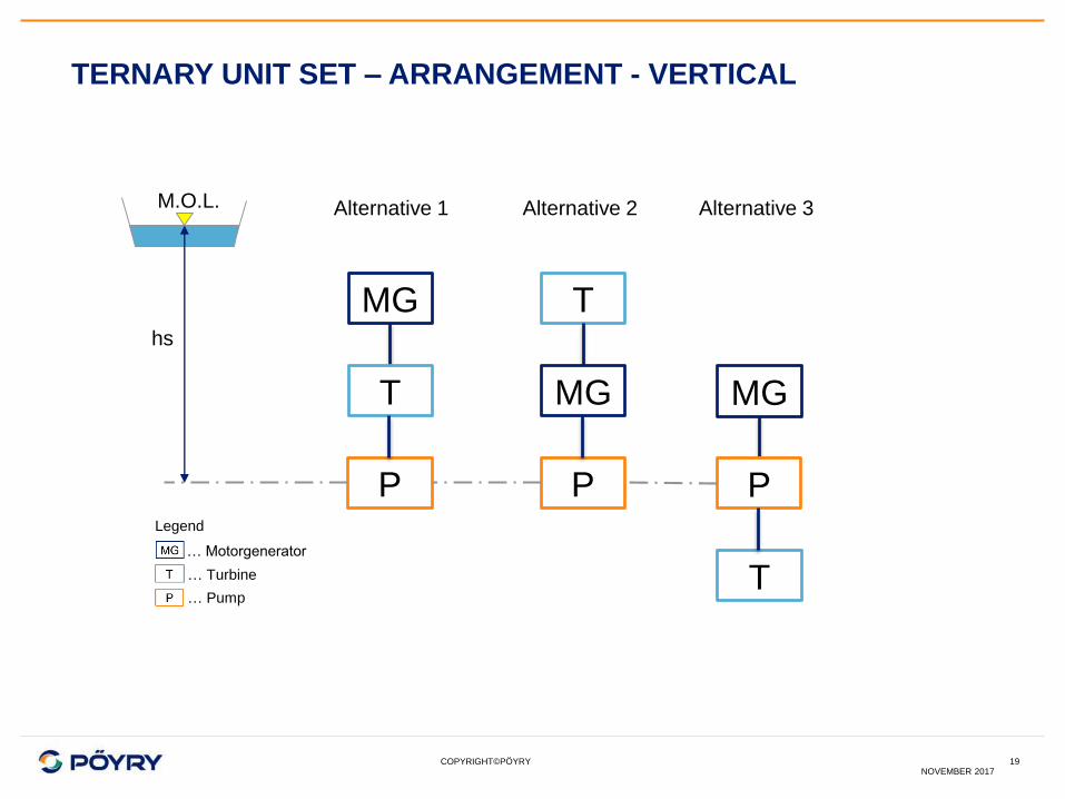
TERNARY UNIT SET – ARRANGEMENT - VERTICAL
MG
T
P
T
MG
P
T
MG
P
Alternative 1 Alternative 2 Alternative 3M.O.L.
hs
… Motorgenerator
… Turbine
… Pump
Legend

COPYRIGHT©PÖYRYNOVEMBER 2017
20
TERNARY UNIT SET - DESIGN CHALLENGE
MG
T
P
hs
M.O.L.
F.S.L.
~11 m
hf
Motorgenerator
Pelton-Turbine
with mandatory free board
Shaft length!
Multistage Pump
with mandatory suction head

COPYRIGHT©PÖYRYNOVEMBER 2017
21
TERNARY UNIT SET - 75 MW UNIT SET
Pelton Turbine
Converter
Multistage Pump
Motorgenerator
COPYRIGHT©PÖYRYNOVEMBER 2017
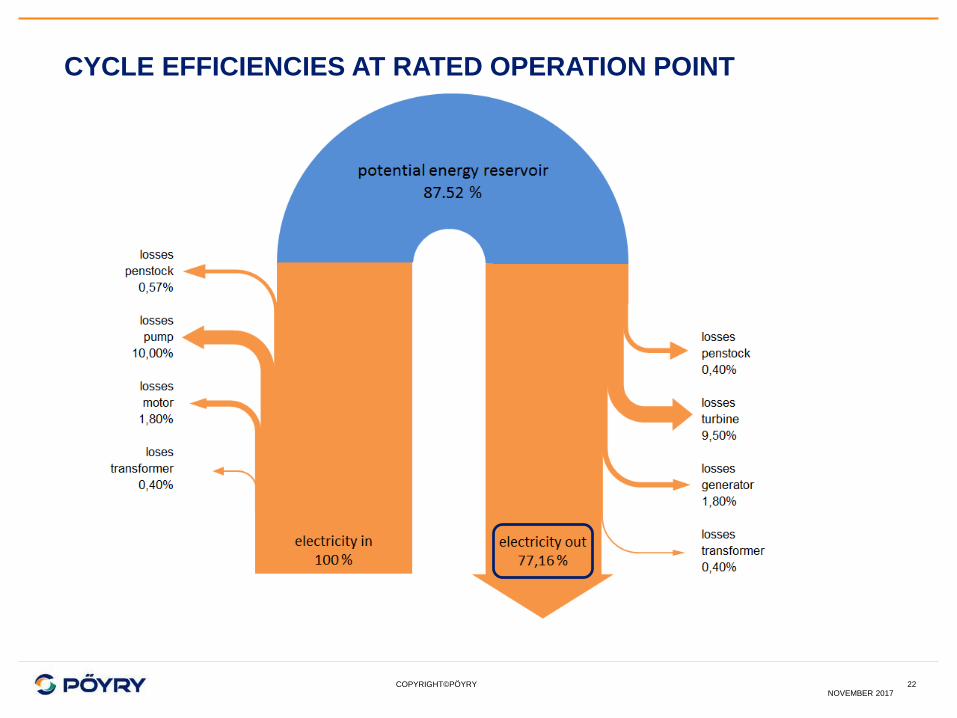
22
CYCLE EFFICIENCIES AT RATED OPERATION POINT

COPYRIGHT©PÖYRY
TRANSPORT LOGISTICS
NOVEMBER 201723
• Transport of large E&M equipment to depth level of -1400 m is considered as critical
• Existing decline tunnel has steep gradient, narrow curve radius and restricted cross-
section
• Transport study showed that curves have to widened by about 1,5 m.

COPYRIGHT©PÖYRY
CONCLUSION
NOVEMBER 201724
• Preferred location at -1400 m depth in order to utilise the full head and to minimise
related storage volume.
• No technical “show stoppers” have been identified.
• Technical and construction advantages due to excellent geological conditions.
• Ternary unit set with pressured turbine-tailwater chamber is the preferred arrangement.
• Specific costs are in the lower range compared to other PS projects.
• Economic evaluation (Pöyry’s BID3 market model) showed challenging conditions for PS
in Finland.
If realised it will
likely be the
pumped -storage
plant with the
highest head
worldwide.

COPYRIGHT©PÖYRY
70%
with higher
academic
degree
45countries
50languages
spoken
10,000projects
delivered
annually
6,000 experts
150offices
70nationalities
WE ARE PÖYRY – THE CONNECTED COMPANY
CLIENT
FOCUS
Delivering consulting,
engineering, project execution
and operational services.
Global community of talented
people working closely with
clients locally.
Inspiring new solutions by
connecting deep expertise
and profound insight.
Contributing to projects that
make a difference.
INDUSTRYENERGY INFRA
25NOVEMBER 2017

COPYRIGHT©PÖYRY
ENERGY – EMPOWERING YOUR BUSINESS
• Thermal power & Renewable energy
• Hydropower
• Transmission & distribution
• Nuclear energy
* RANKED #
8OVER
60 GW
DELIVERED
200+
CONTRIBUTED TO
10%
in power generation
globally *
total hydropower
capacity globally
total combined
capacity of thermal
power plant projects
wind power
projects
Consulting. Engineering. Projects. Operations. * source: ENR 2015
26NOVEMBER 2017

COPYRIGHT©PÖYRY
INFORMATION
NOVEMBER 201727

Consulting. Engineering. Projects. Operations. www.poyry.com
Contact:
Ernst Zeller