Embed Size (px)
Citation preview

Full Terms & Conditions of access and use can be found athttp://www.tandfonline.com/action/journalInformation?journalCode=taut20
AutomatikaJournal for Control, Measurement, Electronics, Computing andCommunications
ISSN: 0005-1144 (Print) 1848-3380 (Online) Journal homepage: http://www.tandfonline.com/loi/taut20
An improved startup mode using clutch couplingfor in-wheel electric vehicle drives
Ping Xiong & Chenglin Gu
To cite this article: Ping Xiong & Chenglin Gu (2017) An improved startup mode usingclutch coupling for in-wheel electric vehicle drives, Automatika, 58:1, 97-110, DOI:10.1080/00051144.2017.1361612
To link to this article: https://doi.org/10.1080/00051144.2017.1361612
© 2017 The Author(s). Published by InformaUK Limited, trading as Taylor & FrancisGroup
Published online: 17 Aug 2017.
Submit your article to this journal
Article views: 366
View Crossmark data
REGULAR PAPER
An improved startup mode using clutch coupling for in-wheelelectric vehicle drives
Ping Xiong and Chenglin Gu
School of Electrical and Electronic Engineering, Huazhong University of Science & Technology, Wuhan, Hubei, P.R. China
ARTICLE HISTORYReceived 30 September 2016Accepted 20 July 2017
ABSTRACTBy introducing a new type of clutch into the driveline system of an in-wheel drive electricvehicle, a flexible connection has been developed to replace the rigid one between the huband the motor. The driving motor can realize variable idling, unlike the internal combustionengine, which needs a minimum rotational speed. This paper proposes a new startup methodthat utilizes the initial kinetic energy of the motor to achieve a smooth and fast acceleration ofthe wheel speed from zero to the expected motor speed. First, the powertrain system,including the driving motor, the clutch and the vehicle resistance, is modelled. Second, factorsinfluencing the starting current and the jerk level during the starting process are investigated.In consequence, the idle speed can be interpreted as a tunable variable that determines thetradeoff between the torque capacity and the jerk level. Finally, simulation and experiments ona laboratory test rig are performed. The results validate that the proposed variable-idle speedcontrol strategy has a lower jerk level and lower starting current when compared with thoseusing a direct start under the same load condition.
KEYWORDSClutch coupling; startupmode; variable-idle speed;vehicle jerk
1. Introduction
The increasing awareness regarding air pollution andthe energy crisis draws the attention of many research-ers to the development of alternative-fuel vehicles [1].Different kinds of green cars (e.g. hybrid electricvehicles, fuel-cell vehicles and pure electric vehicles)have been widely promoted in recent years. Althoughthe traditional centralized-drive mode is adopted inmost of them, the in-wheel drive mode is currentlyconsidered to be an attractive candidate for the electricvehicle (EV) propulsion system because of its promi-nent advantages, such as lower drivetrain losses, alightweight body structure, high energy efficiency andlow road noise [2,3].
The force that resists wheel motion is mainly causedby factors such as deformations of the wheel and theroadbed, bearing losses, and slippage between thewheel and the surface. The problem of vehicle startupbecomes prominent, especially taking into account theadditional resistance forces arising from the static fric-tion of bearings or the relative micro-sliding betweenthe surfaces of contact [4,5]. In the case of a vehiclestarting from a dead stop, the resistive force caused bythe bearing friction can actually be a larger portion ofthe vehicle’s total rolling resistance [5]. Thus, morepower is required to accelerate the wheel from a stand-still, i.e. the larger driving torque of the motor has tobe guaranteed when the motor is rigidly connected tothe stationary driveline of the vehicle. Additionally, the
voltage surge that results from the higher di/dt maydamage the components, such as the Hall sensors andthe controllers, if the EV brakes at a high speed [6].Therefore, unsatisfactory starting performance anduncomfortable feelings to drivers will be inevitablyproduced with a rigid connection between the hub andthe motor, in particular during the starting and brak-ing processes.
Combined with the advanced control strategy, theclutch mechanism has been commonly used in thedriveline of internal combustion engine vehicles andhybrid electric vehicles for reducing mechanical shockand improving the comfort level when starting the vehi-cle or shifting gears [7,8]. It is also applied to decreasethe electromagnetic impulsion in the starting of themotor. A centrifugal clutch is used to assist with motorstarting. The basic operating principle is to employ cen-trifugal force to engage or disengage automatically fromthe load at a certain rotating speed, which will result ina reduction in the residence time of electromagneticimpulsion and accumulated heat in the armature wind-ing during the starting process [9]. Additionally, thepermanent magnet (PM) coupling is considered a solu-tion for oversizing the driving motor, especially for thestarting of large-inertia equipment [10]. In addition, thedog clutch has been adopted and tested within an elec-tric drivetrain to verify the effectiveness of the energysavings by disengaging the propulsion motor from thewheels during coasting events [11].
CONTACT Ping Xiong [email protected]
© 2017 The Author(s). Published by Informa UK Limited, trading as Taylor & Francis GroupThis is an Open Access article distributed under the terms of the Creative Commons Attribution License (http://creativecommons.org/licenses/by/4.0/), which permits unrestricteduse, distribution, and reproduction in any medium, provided the original work is properly cited.
AUTOMATIKA, 2017VOL. 58, NO. 1, 97–110https://doi.org/10.1080/00051144.2017.1361612

As stated above, the value of including the clutchmechanism within the drivetrain is examined. Severaltypes of clutch mechanisms have been reported in lit-eratures so far. Most of them are concerned with amechanically controlled clutch or a centrifugal clutchmechanism concentrated mainly on the centralized-drive conditions [8,12]. However, there seem to be fewreferences regarding the utilization of the clutch mech-anism for the application of an in-wheel drive EV.Several cases have been covered in references or pat-ents concerning the so-called “pulse and glide” drivingstrategy and the optional switch between a pedal driveor a motor drive in the motorized bicycle drive system[11,13], in which the dog clutch or the overrun clutchis used to disengage the propulsion motor from thewheel load.
Therefore, a new type of clutch is especiallydesigned for the restricted space between the hub andthe motor. Its operating principle and design ruleswere investigated in previous work [14]. As shown inFigure 1(a), the armature is polarized when the controlcoil is energized. Acted upon by the resultant electro-magnetic force of the PM on one side, the armature ismoved to the other side. Then, the clutch accomplishesthe transfer from open to locked state. Accordingly,the driving torque is transmitted to the wheel after thepush rods slide into the joint holes, as displayed inFigure 1(b). The push rod of the clutch functions as atorque transfer medium for the driveline system.
By applying either the friction pairs or the dogclutch pairs that are placed, respectively, at the wheel
hub and the motor side, different assemblies of theclutch units can be achieved. One demonstration isshown in Figure 1(b). Several joint holes providing auniform division of a circle are laid at the wheel huband they correspond to the clutch’s push rods.Composed of several clutch units that are uniformlymounted on the external surface of the hub motor, theactuator functions like a dog clutch for the powertransmission and interruption between the motor(driving end) and the wheel (driven end) of an in-wheel electric drive system.
As key parts of the clutch system, this paper mainlyfocuses on the startup method highlighted by “no-loadstarting” and “variable-idle shifting” together. Basedon the behaviour of an instantaneous engagement pro-cess between the motor and the wheel, the paper pro-poses an ideal clutch model that complies with theprinciple of conservation of angular momentum,which is distinguished from the control of the pressureor the displacement profile of the clutch. Accordingly,the no-load speed of the motor, i.e. the so-called idlespeed, is chosen, aiming at balancing the jerk level andthe starting current based on load conditions. Thestartup of the EV with a rigid connection between themotor and the hub is referred to as “direct start”. Cor-respondingly, the separated process of motor startupand load operation is referred to as “clutch start”.
2. Modelling the powertrain
The simplified powertrain of the in-wheel drive systempresented in the article consists of three parts: the driv-ing motor, the clutch and the vehicle resistance. Someassumptions are made before modelling. Ignoring thewheel slip, the vehicle mass can be regarded as a con-centrated mass referred to the rotational shaft of thedriving motor.
2.1. Modelling of the driving motor
Because the motor selection will have little effect onperformance comparisons between the direct start andthe clutch start, a DC motor is chosen as the mainpower unit of the driveline system to simplify the anal-ysis. The DC drive system model is composed of anelectrical equation and a mechanical equation,
Ladiadt
þ iaRa þ E ¼ ua; (1)
Jedve
dt¼ Te � TM; (2)
where Ra is the armature resistance, La is the armatureinductance, ia is the armature current, ve is themechanical angular speed, ua is the input voltage, Je isthe motor inertia, Te is the output torque of the electricmachine, TM is the load torque, and E is the back EMF
Figure 1. Schematic diagram of the assembly of clutch unitsbetween the hub and the motor in an in-wheel drive system:(a) a new type of clutch unit, (b) demonstration of the assem-bly of clutch units between the hub and the motor in an in-wheel drive system.
98 P. XIONG AND C. GU

(electromotive force), which is described by
E ¼ Keve; (3)
where Ke is the EMF constant of the electric motor.
2.2. Modelling of the vehicle dynamics
The resistive force acting upon the vehicle is generallythe summation of the aerodynamic drag, rolling resis-tance, inclination force and acceleration [15]. Ignoringthe rotational parts of the wheel, the vehicle mass islumped into a single inertia referred to the rotationalshaft of the driving motor,
Jv ¼ Mvr2w=G
2; (4)
where Mv is the gross mass including the load, rw is thetire radius, Jv is the equivalent moment of inertia referredto the rotational shaft of the driving motor, and G is thegear ratio, which has a value of 1 in direct-drive mode.
Additionally, air resistance is small enough to beignored because the vehicle speed remains fairly lowat the initial instant of startup. Combined with theelectrical and mechanical equations of the DC motor,the following equations show the overall model of thedirect-drive EV system:
Ladiadt
þ iaRa þ Keve ¼ ua
ðJe þMvr2wG2
Þ dve
dt¼ KTia � rw
GðfrMvg þMvgsin uÞ;
(5)
where g is the acceleration of gravity, fr is the coeffi-cient of rolling friction, u is the inclination angle, andKT is the torque constant of the DC motor.
The resistance torque applied to the wheel on levelground is always influenced by the rolling loss group,which is attributed to factors such as the bearing lossesand the deformation between the wheel and the road-bed surface. Based on the variation law of the frictioncoefficient of the bearing, the friction coefficient tendsto have a relatively high value when the vehicle travelsat a low driving speed or accelerates from a standstill[16]. Additionally, the rolling resistance is likewise theresult of deformations occurring at the point of contactbetween the tire and the road. Road roughness willinfluence the tire–road frictional behaviour, and itraises static resistance with little effect on dynamicresistance [17]. Therefore, the effects of bearing fric-tion and the tire–road frictional behaviour should bedistinguished between the rolling and non-rolling sit-uations. In some cases, the total resistance torque act-ing upon the wheel at the initial instant of startupcould be several times larger than the one when thewheel rolls at a steady speed [16,18].
In general, the frictional behaviour of contact surfa-ces is often modelled as a basic Coulomb frictionmodel, a static-kinetic friction model, or a stick-slipfriction model [4]. In consideration of the complexityof characterizing the nonlinear frictional propertieswith an expression that should be determined throughextensive experiments on a test vehicle, the static-kinetic friction model is taken into account in thisarticle. Namely, a constant dynamic coefficient oper-ates at all rolling speeds, whereas a higher static coeffi-cient operates at the beginning. The symbol fs,which corresponds to the force to start motion, wouldrepresent the static coefficient of rolling friction.Correspondingly, the symbol fr would represent thedynamic coefficient, which is operative for the movingcondition [19].
2.3. Modelling of sudden clutch engagement
By implementing the clutch start, there exists a speeddifference between the motor and the wheel before theclutch engages. Two possible scenarios are distin-guished during the starting period and are described asthe synchronizing and engaged phases. The dynamicprocess of clutch engagement during the synchroniz-ing phase can be presented as
Je _ve ¼ Te � Tc; (6)
Jv _vv ¼ Tc � TL; (7)
where Tc is the clutch torque, vv is the angular speed ofthe wheel, and TL is the total resistance torque actingon the wheel.
Acted upon by the clutch torque Tc, the motorspeed is decreased while the wheel speed is increased.Accordingly, the motor speed during this phase is gov-erned by the following equation:
Z tc
0ðTe � TcÞdt ¼
Z v1
v0
Jedv; (8)
whereas the wheel speed is governed by
Z tc
0ðTc � TLÞdt ¼
Z v1
0Jvdv; (9)
where v0 is the no-load angular speed of the motor, v1
is the angular speed at the clutch lockup instant, and tcis the elapsed time for the clutch engagement.
The angular impulse is the time integration of thetorque. The impulse that is produced by the drivingtorque and the clutch torque will act upon the motor,while the loading torque and the clutch torque will actupon the wheel. Based on the principle of impulse,the action of the impulse can be equivalent to an aver-age torque by the time during which it acts. Once thespeed difference between the motor and the wheel
AUTOMATIKA 99
approaches zero, the clutch has been transitioned intothe locked state from the open state. Then, the elapsedtime for the clutch engagement can be calculated by
tc ¼ v0JeJvJvðTc � TeÞ þ JeðTc � TLÞ : (10)
Moreover, in the numerical and experimental meas-urements carried out in [20,21], the action of rapidclutch engagement always produces high drivelineloads over a short duration in the engine mounts anddriveline components. In this case, supposing theequivalent clutch torque is far greater than the motortorque and the resistance torque, Equation (10) can bereduced to the following equation:
tcTc
Jv¼ Jev0
Je þ Jv: (11)
It is noted from Equation (11) that the variation ofwheel speed during this phase is simply proportionalto the zero-load speed v0.
Furthermore, a rigid connection is made betweenthe wheel and the motor while the clutch remains in alocked state, and while in an open state it transmitszero force (or torque). Analogous to ideal electricalswitches, it is assumed that the ideal mechanical cou-pling between two masses rotating at different speedsengages or disengages instantaneously. Hence, thepaper treats such an event as a completely inelastic col-lision, and the principle of conservation of angularmomentum is applied to calculate the collision speed[22]. The common angular speed when the clutch isinstantly locked is governed by
v1 ¼ Jev0
Je þ Jv: (12)
Equation (12) implies that the common angularspeed v1 obtained by the ideal mechanical couplingagrees with the result of the left-hand side of Equation(11). The action of rapid engagement of the clutch canbe considered to be in accord with an ideal clutch thatcan instantaneously open or close. Additionally, thederived equation as shown in Equation (11) notes thatcommon angular speeds are obtained by the motorand the wheel via the operation of rapid engagementof the clutch. Then, the wheel is flexibly coupled to themotor, behaving like a linking element. The single-degree-of-freedom (single-DOF) dynamic model ofthe clutch at the engaged phase is presented as
Te � TL ¼ ðJe þ JvÞ dve
dt: (13)
In [4], a typical response of the wheel momentand the wheel angular velocity is measured during a
“snap-start” experiment with a standing and rollingstart. It is indicated that there is a transient processwith high peak values of oscillations, and the peakvalue of the wheel moment in the case of a standingstart is higher than that in the case of a rolling start. Inaddition, the increase of wheel speed will help toreduce the free rolling resistance force and wheel sink-age [23]. To some extent, the required tractive torquefor accelerating the wheel from a standstill would bedecreased as a result of the initial speed obtained bythe wheel via the operation of sudden engagement ofthe clutch.
3. Variable-idle speed control strategy forvehicle startup
3.1. Performance indices
The criterion for evaluating the comfort level of vehiclestartup or shifting is susceptible to the subjective per-ception of human beings. In general, the change rate ofacceleration reflects the force variation on an object,which exactly accounts for the phenomenon of the“head nod” effect on passengers during vehicle shiftingor the sense of uncomfortable feelings in the case of ele-vator starting and stopping. Neglecting the vertical andlateral vibrations, the change rate of the vehicle’s longi-tudinal acceleration, called jerk, is considered as theobjective index of driving comfort [24]. Uncomfortablephysiological feelings will be experienced as long as theabsolute value of the jerk level is beyond the recom-mended value of 10 m/s3 [25]. In addition, the peakarmature current and the armature heating during thestarting process are seen as the performance indices forquantifying the level of electromagnetic impulsion.
3.2. Determination of the idle speed for theimprovement to performance indices
The minimum rotational speed of the engine, which isapproximately 10%–15% of its maximum speed, isgenerally sufficient to assure an acceleration of thewheel speed from zero to engine speed under normaldriving conditions [26]. Similarly, the same ratio of amotor’s rated speed is matched with its fixed idlespeed. However, because of the limitation of the start-ing torque of the driving motor when it is engaged tothe wheel at a fixed idle speed, potential negative accel-eration of the wheel would occur after the rapid clutchengagement. Therefore, the variable-idle speed controlscheme is proposed to find a balance between thereduction in jerk level and the improvement of torquecapacity. The specific flowchart for variable-idle speedcontrol strategy is shown in Figure 2.
In practical applications, the initial force that resistswheel motion, i.e. the starting resistance, can beapproximately estimated from the sensors or the initial
100 P. XIONG AND C. GU
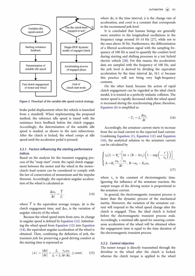
brake pedal displacement when the vehicle is launchedfrom a standstill. When implementing the proposedmethod, the reference idle speed is tuned with theresistance force feedback before the clutch engages.Accordingly, the determination of the suitable idlespeed is studied, as shown in the next subsections.After the clutch is locked, the wheel creeps at idlespeed until the accelerator pedal is pressed.
3.2.1. Factors influencing the starting performanceindicesBased on the analysis for the transient engaging pro-cess of the “snap-start” event, the rapid clutch engage-ment between the motor and the wheel in the motor–clutch–load system can be considered to comply withthe law of conservation of momentum and the impulsetheorem. Accordingly, the equivalent angular accelera-tion of the wheel is calculated as
Dvv
Dt¼ T
Jv; (14)
where T is the equivalent average torque, Dt is theclutch engagement time, and Dvv is the variation ofangular velocity of the wheel.
Because the wheel speed starts from zero, its changein angular speed is defined by Equation (12). Substitut-ing the wheel speed from Equation (12) into Equation(14), the equivalent angular acceleration of the wheel isobtained. Then, combining the definition of jerk, thetransient jerk for preserving a good driving comfort atthe starting time is expressed as
j _a j ¼ dadt
�������� ¼ Je
Je þ Jv
rwv0
Dt�Dts � const; (15)
where Dts is the time interval, _a is the change rate ofacceleration, and const is a constant that correspondsto the recommend jerk level.
It is concluded that human beings are generallymore sensitive to the longitudinal oscillations in thefrequency range around 10–14 Hz [27], while not tothe ones above 50 Hz. Furthermore, the differentiationof a filtered acceleration signal with the sampling fre-quency of 100 Hz is used to quantify the comfort levelduring starting and shifting processes in a test hybridelectric vehicle [28]. For this reason, the accelerationdata are sampled with the frequency of 100 Hz, andthe jerk level is derived by dividing the equivalentacceleration by the time interval Dts (0.1 s) becausethis practice will not bring very high-frequencycontents.
On the other hand, because the action of rapidclutch engagement can be regarded as the ideal clutchmodel, it is treated as a perfectly inelastic collision. Themotor speed is rapidly decreased while the wheel speedis increased during the synchronizing phase; therefore,Equation (6) is simplified as
�Tc ¼ Jedve
dt: (16)
Accordingly, the armature current starts to increasefrom the no-load current to the expected load current.Combining Equation (1), Equation (12) and Equation(16), the analytical solution to the armature currentcan be calculated by
iaðtÞ ¼ R�1a At þ ðB� AtaÞ 1� exp � t
ta
� �� �� �
A ¼Kev0 � v1
Dt; B ¼ua � Kev0
;
8><>:
(17)
where ta is the constant of electromagnetic time.Ignoring the influence of the armature reaction, theoutput torque of the driving motor is proportional tothe armature current.
In general, the electromagnetic transient process isfaster than the dynamic process of the mechanicalinertia. Moreover, the variation of the armature cur-rent will respond to the wheel speed change after theclutch is engaged. Thus, the ideal clutch is lockedbefore the electromagnetic transient process ends.Accordingly, a minimal idle speed for assuring contin-uous acceleration of the wheel will be obtained whenthe engagement time is equal to the time duration ofthe electromagnetic transient process.
3.2.2. Control objectiveThe motor torque is directly transmitted through thedriveline to the wheel after the clutch is locked,whereas the clutch torque is applied to the wheel
Figure 2. Flowchart of the variable-idle speed control strategy.
AUTOMATIKA 101
during the synchronizing phase. Obviously, there is asudden change in the clutch torque at speed synchro-nization instant, and the discontinuity in angularacceleration of the wheel at the clutch lockup timeinstant t is proportional to the slip angular accelerationjust before the clutch is locked according to [29],
_vvðtþÞ � _vvðt�Þ ¼ JeJe þ Jv
_vslðt�Þ_vslðt�Þ ¼ _veðt�Þ � _vvðt�Þ
;
8<: (18)
where _vslðt�Þ is the slip angular acceleration before theclutch is locked, _vvðt�Þ and _vvðtþÞ are the angularaccelerations of the wheel at the time instant of clutchpre-lockup and post-lockup, i.e. the time prior to theclutch lockup time instant is referred to as the pre-lockup phase, whereas the time after that is referred toas the post-lockup phase, and veðt�Þis the angularspeed of the driving motor just before the clutch islocked.
For the same time interval, the jerk level amountsto the discontinuity of the wheel acceleration. Giventhat the angular speed variation of the motor is farlarger than that of the wheel over the same time span, thediscontinuity in angular acceleration of the wheel at theclutch lockup time instant can be approximately equiva-lent to the jerk level while the clutch instantaneouslyengages. In comprehensive consideration of (15) and(18), the idle speed should be restricted to a certain rangefor ensuring the discontinuity of the wheel accelerationsboth before and after the clutch lockup time.
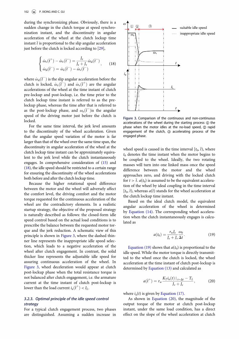
Because the higher rotational speed differencebetween the motor and the wheel will adversely affectthe comfort level, the driving comfort and the motortorque requested for the continuous acceleration of thewheel are the contradictory elements. In a realisticstartup strategy, the objective of the proposed strategyis naturally described as follows: the closed-form idlespeed control based on the actual load conditions is toprescribe the balance between the requested motor tor-que and the jerk reduction. A schematic view of thisprinciple is shown in Figure 3, where the dashed thin-ner line represents the inappropriate idle speed selec-tion, which leads to a negative acceleration of thewheel after clutch engagement. In contrast, the solidthicker line represents the adjustable idle speed forassuring continuous acceleration of the wheel. InFigure 3, wheel deceleration would appear at clutchpost-lockup phase when the total resistance torque isnot balanced after clutch engagement, i.e. the armaturecurrent at the time instant of clutch post-lockup islower than the load current iaðtþÞ< IL.
3.2.3. Optimal principle of the idle speed controlstrategyFor a typical clutch engagement process, two phasesare distinguished. Assuming a sudden increase in
wheel speed is caused in the time interval [t0, t), wheret0 denotes the time instant when the motor begins tobe coupled to the wheel. Ideally, the two rotatingmasses will turn into one linked mass once the speeddifference between the motor and the wheelapproaches zero, and driving with the locked clutchfor t > t. a(t0) is assumed to be the equivalent accelera-tion of the wheel by ideal coupling in the time interval[t0, t), whereas a(t) stands for the wheel acceleration atthe clutch lockup time instant.
Based on the ideal clutch model, the equivalentangular acceleration of the wheel is determinedby Equation (14). The corresponding wheel accelera-tion when the clutch instantaneously engages is calcu-lated as
aðt0Þ ¼ rwJeJe þ Jv
v0
Dt: (19)
Equation (19) shows that a(t0) is proportional to theidle speed. While the motor torque is directly transmit-ted to the wheel once the clutch is locked, the wheelacceleration at the time instant of clutch post-lockup isdetermined by Equation (13) and calculated as
aðtþÞ ¼ rwKTiaðtÞ j t¼Dt � TL
Jv þ Je; (20)
where ia(t) is given by Equation (17).As shown in Equation (20), the magnitude of the
output torque of the motor at clutch post-lockupinstant, under the same load condition, has a directeffect on the slope of the wheel acceleration at clutch
Figure 3. Comparison of the continuous and non-continuousaccelerations of the wheel during the starting process: thephase when the motor idles at the no-load speed, rapidengagement of the clutch, accelerating process of theengaged phase.
102 P. XIONG AND C. GU
post-lockup instant. Therefore, the slope of this accel-eration–speed relationship (a(tþ) ¡ v0) is equal to theslope of torque–speed relationship (Te(t
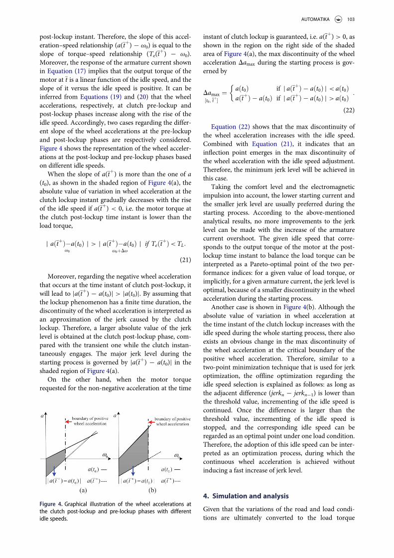
þ) ¡ v0).Moreover, the response of the armature current shownin Equation (17) implies that the output torque of themotor at t is a linear function of the idle speed, and theslope of it versus the idle speed is positive. It can beinferred from Equations (19) and (20) that the wheelaccelerations, respectively, at clutch pre-lockup andpost-lockup phases increase along with the rise of theidle speed. Accordingly, two cases regarding the differ-ent slope of the wheel accelerations at the pre-lockupand post-lockup phases are respectively considered.Figure 4 shows the representation of the wheel acceler-ations at the post-lockup and pre-lockup phases basedon different idle speeds.
When the slope of a(tþ) is more than the one of a(t0), as shown in the shaded region of Figure 4(a), theabsolute value of variation in wheel acceleration at theclutch lockup instant gradually decreases with the riseof the idle speed if a(tþ) < 0, i.e. the motor torque atthe clutch post-lockup time instant is lower than theload torque,
j aðtþÞ�aðt0Þv0
j > j aðtþÞ�aðt0Þv0þDv
j if TeðtþÞ<TL:
(21)
Moreover, regarding the negative wheel accelerationthat occurs at the time instant of clutch post-lockup, itwill lead to ja(tþ) ¡ a(t0)j > ja(t0)j. By assuming thatthe lockup phenomenon has a finite time duration, thediscontinuity of the wheel acceleration is interpreted asan approximation of the jerk caused by the clutchlockup. Therefore, a larger absolute value of the jerklevel is obtained at the clutch post-lockup phase, com-pared with the transient one while the clutch instan-taneously engages. The major jerk level during thestarting process is governed by ja(tþ) ¡ a(t0)j in theshaded region of Figure 4(a).
On the other hand, when the motor torquerequested for the non-negative acceleration at the time
instant of clutch lockup is guaranteed, i.e. a(tþ) > 0, asshown in the region on the right side of the shadedarea of Figure 4(a), the max discontinuity of the wheelacceleration Damax during the starting process is gov-erned by
Damax½t0; tþ�
¼ aðt0Þ if j aðtþÞ � aðt0Þ j < aðt0ÞaðtþÞ � aðt0Þ if j aðtþÞ � aðt0Þ j > aðt0Þ
:
�
(22)
Equation (22) shows that the max discontinuity ofthe wheel acceleration increases with the idle speed.Combined with Equation (21), it indicates that aninflection point emerges in the max discontinuity ofthe wheel acceleration with the idle speed adjustment.Therefore, the minimum jerk level will be achieved inthis case.
Taking the comfort level and the electromagneticimpulsion into account, the lower starting current andthe smaller jerk level are usually preferred during thestarting process. According to the above-mentionedanalytical results, no more improvements to the jerklevel can be made with the increase of the armaturecurrent overshoot. The given idle speed that corre-sponds to the output torque of the motor at the post-lockup time instant to balance the load torque can beinterpreted as a Pareto-optimal point of the two per-formance indices: for a given value of load torque, orimplicitly, for a given armature current, the jerk level isoptimal, because of a smaller discontinuity in the wheelacceleration during the starting process.
Another case is shown in Figure 4(b). Although theabsolute value of variation in wheel acceleration atthe time instant of the clutch lockup increases with theidle speed during the whole starting process, there alsoexists an obvious change in the max discontinuity ofthe wheel acceleration at the critical boundary of thepositive wheel acceleration. Therefore, similar to atwo-point minimization technique that is used for jerkoptimization, the offline optimization regarding theidle speed selection is explained as follows: as long asthe adjacent difference (jerkn ¡ jerkn¡1) is lower thanthe threshold value, incrementing of the idle speed iscontinued. Once the difference is larger than thethreshold value, incrementing of the idle speed isstopped, and the corresponding idle speed can beregarded as an optimal point under one load condition.Therefore, the adoption of this idle speed can be inter-preted as an optimization process, during which thecontinuous wheel acceleration is achieved withoutinducing a fast increase of jerk level.
4. Simulation and analysis
Given that the variations of the road and load condi-tions are ultimately converted to the load torque
Figure 4. Graphical illustration of the wheel accelerations atthe clutch post-lockup and pre-lockup phases with differentidle speeds.
AUTOMATIKA 103

applied to the driving motor, the performance compar-isons between the direct start and the clutch start areinvestigated under the same load condition. As the keyelement of an in-wheel EV drive, the hub motor is fea-tured by high torque and low speed. First, similar tothe features of a hub motor, the parameters of the driv-ing motor are considered for an in-wheel drivecondition.
In general, the rolling coefficient is approximately0.01–0.018 under normal driving conditions. As men-tioned in Section 2, taking into account the bearingfriction or the complex tire–road interactions, the sta-tionary resistance torque at the initial instant of start-ing can reach several times the value of the rolling one.Hence, in the case of a vehicle starting from a stand-still, a working condition where the fs is assumed to bethree times as much as the fr is considered. The simula-tion parameters of a lightweight EV and the drivingmotor are specified in Table 1.
Because the road and load conditions are widelyvaried, the scheme of reducing the voltage across thearmature without current limiting is commonlyadopted for the motor starting with the load. Duringthis case, the peak current is governed by
I�max ¼u�aR�a: (23)
Note that variables, respectively, with superscript �
and subscript “N” stand for the per-unit value and therated value. The average jerk value is calculated by thedifferentiating Equation (13) with respect to time,
_a ¼ dadt
¼ rwJv þ Je
dTe
dt¼ rwKT
Jv þ Je
diadt
: (24)
Equation (24) shows that the torque variation isequivalent to the change rate of the acceleration, whichis the same as the physical significance of the jerk.Equations (23) and (24) suggest that reducing theinput voltage across the armature is advantageous fordecreasing the starting current and increasing the com-fort level. However, it will cause a longer starting timeof the motor. The wheel stays stationary until sufficient
motor torque is supplied to overcome the startingresistance moment, i.e. the armature current increasesto the load current IL from the no-load current. Duringthis phase, the response of the armature current isdetermined by
iaðtÞ ¼ uaRa
1� exp � tta
� �� �: (25)
Accordingly, the elapsed time td when the wheel isset into motion is governed by the solution of equationIL = ia(t), and it is described as follows:
td ¼ � 1taln 1� TLRa
uaKT
� �: (26)
Because of the fact that the electrical time constantof the motor is negligibly small compared with themechanical time constant of the driveline system, theper-unit value of total dissipated energy in the wind-ings of the motor or equivalent heating in the armatureover the starting period is determined by [30] to be
Q�¼Z tr
0ðI�max � I�z Þexp � t
tm
� �þ I�z
� �2dt: (27)
tm is the mechanical time constant of the drivelinesystem, tr is the elapsed time from rest to steady loadspeed, and Iz is the steady load current.
Next, on the premise of the minimum tractive tor-que to propel the vehicle into motion, the clutch startand the direct start are simulated under the same loadcondition for comparison. The contrast curves of themotor and wheel speeds, armature current, equivalentarmature heating and jerk level are sequentially shownin Figure 5. The rated current and the recommendedjerk value are the base values of the armature currentand the jerk level.
As shown in Figure 5(a), the motor is idling atapproximately 30 r/min (ne) before the clutch engages.At time instant 1 s, the motor begins to connect to thewheel. Because of the significant loads for a short dura-tion among the driveline components by the idealengaging process, it will lead to momentum transferfrom the motor to the wheel. Correspondingly, thequick deceleration of the motor is acquired while thewheel is obtained with an initial speed.
Ideally, based on the simple model as described inSection 2, the transition between the static and kineticconditions occurs when the common speeds of themotor and the wheel are obtained by an ideal clutch.Thus, the dynamic resistance torque needs to be over-come to maintain the wheel speed in the creep modeafter clutch engagement. In contrast, as indicated byEquation (26), the wheel starts rotation when thearmature current rises to compensate the static
Table 1. Simulation parameters of the vehicle and the DCmotor.Name Symbol (unit) Value
DC motorRated voltage UN (V) 60Rated current IN (A) 56Rated speed nN (r/min) 540Armature resistance Ra (V) 0.05Inertia of motor Je (kg m
2) 0.5
VehicleFull load gross mass Mv (kg) 1000Tire radius rw (m) 0.3Gear ratio G 1Static coefficient of rolling friction fs 0.03Dynamic coefficient of rolling friction fr 0.01
104 P. XIONG AND C. GU

resistance torque. As shown in the subgraph of Figure 5(a), the speed curve displayed as a dotted line (nv)shows that the wheel is set into motion at approxi-mately 1.2 s. Apparently, the time instant when thewheel accelerates from zero in the direct start case lagsbehind that using the clutch start. On the minimumtractive torque for accelerating the wheel from a stand-still, the lag time using the direct start is the right timewhen the armature current reaches its peak current.
During the process of the clutch start from 1 s to20 s in Figure 5(b), the armature current rises fromthe no-load current to the expected load current.Figure 5(b) indicates the peak current using the directstart is three times that of using the clutch start. Addi-tionally, in Figure 5(c), the area between the equiva-lent armature heating curves represents the energyreduction using the clutch start, where the energylosses are reduced by 40% during the starting period,compared with the one using the direct start. More-over, the jerk curves using the direct start and theclutch start tend to be zero with the increase of thewheel speed. Figure 5(d) shows that the max jerkvalue using the clutch start is approximately 60% ofthat using the direct start.
Furthermore, the corresponding acceleration curveof the wheel is displayed in Figure 6. There exists anegative acceleration of the wheel during the startingprocess, which accounts for the larger jerk level at theclutch lockup time than the one at the time when theclutch initially engages at the speed of 30 r/min. Then,the armature current at the time instant of the clutchlockup and the max jerk level, respectively, tuned withdifferent idle speeds are graphically demonstrated inFigure 7. An obvious change in the slope of the fittedjerk curve occurs near the idle speed at approximately42 r/min. Figure 7 implies that the fitted jerk curveexhibits an inflection point where the output torque ofthe motor at the clutch lockup time is matched to theload torque at dynamic state (TL
�= 1). The simulation
results are basically in accord with the aforementionedanalysis in Section 3.2.
5. Experiments and analysis
To validate the effectiveness of using the clutch startfor reducing the mechanical and electromagneticshocks further, as well as its optimal idle speed strat-egy, a set of experiments are performed on a laboratory
Figure 5. Comparisons between the direct start and the clutch start under the same load condition: (a) angular speed, (b) armaturecurrent, (c) equivalent armature heating, (d) jerk level.
AUTOMATIKA 105

test rig. A brief description of the experimental setup isshown in Figure 8.
5.1. Test rig
The test rig, as shown in Figure 9, is basically com-posed of the following parts that include the drivingmotor (1), flanges (2) and (7), speed and torque trans-ducer (3), clutch assembly (flywheel, pressure plateand friction disk) (4), clutch operator (5), brake assem-bly (brake disk and friction pairs) (6) and loadingmotor (8). The driving end of the powertrain system iscomposed of the motor and the flywheel. The drivenend is composed of the loading motor in series withthe brake assembly.
Because of its simple control, a separately excitedDC motor is chosen as the driving unit of the drivelinesystem. A speed and torque transducer is placedbetween the driving motor and the clutch assembly tomeasure the load torque and the rotational speed ofthe driving motor. A 30 kW DC motor is located at theend of the driveline, and serves as a generator and thereference moment of inertia of the load. The parame-ters of the driving motor and the loading motor arelisted in Table 2.
For simplifying the construction of the drivelinesystem and focusing on the regulation of the idle speedstrategy, an integrated mechanical clutch is used forthe power transmission and interruption and is con-trolled by the operator arm. The electric machine isinitially increased to the expected idle speed when theclutch is in an open state. Then, for the purpose ofaccelerating the loading motor from a standstill, thesudden engagement of the clutch is finished by quicklyreleasing the pressure plate to utilize the initial kineticenergy of the driving end. In this manner, the impulseloads for a short duration that act upon the drivelinecomponents can be produced by the operation ofthe rapid movement of the pressure plate for lockingthe clutch as quickly as possible. Accordingly, theaction of the angular impulse is transferred to the
Figure 6. Plot of the wheel acceleration when the clutchengages at the speed of 30 r/min.
Figure 7. Plot of the armature current (p.u) at the clutchlockup time and the jerk level for the clutch start at variable-idle speeds.
Figure 8. Description of the experimental setup.
Figure 9. Photograph of the experimental setup for simulatingload startup in direct-drive mode.
Table 2. Parameters of the diving motor and the loadingmotorName Symbol (unit) Value
Driving motorRated voltage UN (V) 110Rated current IN (A) 35Rated speed nN (r/min) 750Armature resistance Ra (V) 0.412Field voltage Uf (V) 220Field current If (A) 1.36Inertia of motor Je (kg m
2) 0.5
Loading motorRated voltage UN (V) 220Rated current IN (A) 160Rated speed nN (r/min) 1500Inertia of motor Jm (kg m2) 2.6
106 P. XIONG AND C. GU
loading motor and is equivalent to the change in angu-lar momentum of the driving end of the powertrainsystem to the greatest extent possible.
Generator dynamometer is commonly used to pro-vide motor load, but it is difficult to achieve a quickloading torque at the initial instant of startup. Thebrake assembly is introduced and is composed of abrake disk, a mechanical actuator and the frictionpairs. It basically defines the mechanical load on thedriven end of the driveline system. The static frictiontorque is applied to the driven end of the driveline sys-tem when contact surfaces between the friction pairsand the brake disk remain at rest, while the dynamicloading torque is produced by the relative slidingbetween them. Therefore, the mechanical load that isproduced by using a disk brake naturally mimics thetransition of resistance force from static to dynamicstate during the starting process. Using this type ofload imitates a condition where the resistance force iscaused by the wheel bearing drag in the case of a vehi-cle starting from a standstill. A simplified character forthe resistance force caused by the braking effect of thedisk brake is followed by using the friction modelreviewed in [31]. The friction force is modelled as afunction of sliding velocity for a case where the staticfriction coefficient is larger than the dynamic frictioncoefficient. In this paper, the resistance force initiallyat rest and at a low rotating speed can be obtainedusing data from the test rig.
Nevertheless, the ideal clutch load transfer via theaction of rapid clutch engagement and dynamic load-ing can be achieved on the test rig mentioned above.The existing experimental setup is still suitable forinvestigations on the regulation of the idle speed con-trol strategy and for validating its effectiveness.
5.2. Comparisons and performance
In the following section, some contrast results areachieved by applying the direct start and the clutchstart, respectively, on the test rig.
In general, the operating velocity of an in-wheeldrive EV is not high. The max velocity of an in-wheeldrive EV is roughly 50–60 km/h in consideration ofthe urban drive cycle. Therefore, the reference inputvoltage ua is limited to 60 V to ensure that the maxangular speed of the driving motor is approximately400 r/min (50 km/h) in this paper. The load accelera-tion is estimated from the sampled speed signal, usinga differentiator with a low-pass filter, where a cut-offfrequency of 100 Hz gives a good balance between thephase lag and the noise. The base value of current isthe rated current (35 A). Additionally, the equivalentjerk _ad is directly calculated by the second derivative ofthe sampled speed and considered for the transversecomparisons of the comfort level in the following tests.
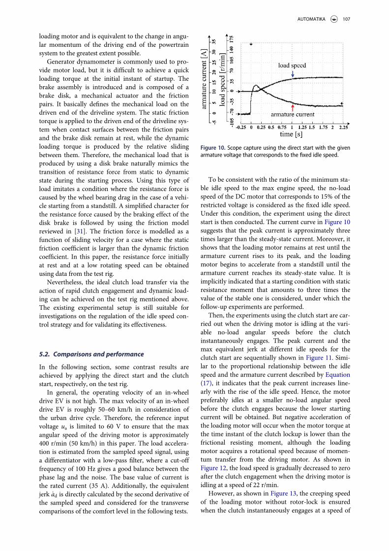
To be consistent with the ratio of the minimum sta-ble idle speed to the max engine speed, the no-loadspeed of the DC motor that corresponds to 15% of therestricted voltage is considered as the fixed idle speed.Under this condition, the experiment using the directstart is then conducted. The current curve in Figure 10suggests that the peak current is approximately threetimes larger than the steady-state current. Moreover, itshows that the loading motor remains at rest until thearmature current rises to its peak, and the loadingmotor begins to accelerate from a standstill until thearmature current reaches its steady-state value. It isimplicitly indicated that a starting condition with staticresistance moment that amounts to three times thevalue of the stable one is considered, under which thefollow-up experiments are performed.
Then, the experiments using the clutch start are car-ried out when the driving motor is idling at the vari-able no-load angular speeds before the clutchinstantaneously engages. The peak current and themax equivalent jerk at different idle speeds for theclutch start are sequentially shown in Figure 11. Simi-lar to the proportional relationship between the idlespeed and the armature current described by Equation(17), it indicates that the peak current increases line-arly with the rise of the idle speed. Hence, the motorpreferably idles at a smaller no-load angular speedbefore the clutch engages because the lower startingcurrent will be obtained. But negative acceleration ofthe loading motor will occur when the motor torque atthe time instant of the clutch lockup is lower than thefrictional resisting moment, although the loadingmotor acquires a rotational speed because of momen-tum transfer from the driving motor. As shown inFigure 12, the load speed is gradually decreased to zeroafter the clutch engagement when the driving motor isidling at a speed of 22 r/min.
However, as shown in Figure 13, the creeping speedof the loading motor without rotor-lock is ensuredwhen the clutch instantaneously engages at a speed of
Figure 10. Scope capture using the direct start with the givenarmature voltage that corresponds to the fixed idle speed.
AUTOMATIKA 107

32 r/min. Because of the different dynamic torquesapplied to the loading motor during the clutch engage-ment period, the load speed curve shows two differentaccelerating phases in Figure 13, and it implies that thecommon speeds of the driving motor and the loadingmotor are acquired before reaching the peak armaturecurrent. Furthermore, the value of the armature
current at the time instant of clutch lockup amounts tothat of the steady-state load current. Moreover, asshown in Figure 11(b), there is an inflection point inthe plotted curve between the idle speed and the jerklevel when the clutch engages at the idle speed of32 r/min. It is implied that no more improvements canbe achieved regarding the equivalent jerk while theundesired larger value of the armature current over-shoot is obtained by increasing the idle speed further.On the whole, the no-load speed when the drivingmotor idles at a speed of 32 r/min can be interpretedas a Pareto-optimal point. The experimental results arebasically in accordance with the aforementioned analy-sis in Section 3.
Subsequently, the contrast results between the directstart and the clutch start are shown in Figure 14. Asexpected, similar results are obtained as with the simu-lation, showing the larger value of the peak currentand the jerk level by using the direct start, althoughfast load acceleration is obtained. Obviously, the com-parison results in Figure 14(a) clearly indicate the load-ing motor begins to accelerate at the instantaneoustime while the clutch engages, which is faster than thetime instant when the loading motor accelerates froma standstill by using the direct start. Moreover, in con-trast to the performance indices of using the directstart, the peak current and the max jerk value by usingthe clutch start are reduced approximately by 67% and50%, as shown in Figure 14(b,d). Accordingly, the cur-rent curve by using the clutch start is a concave-upward response function, which is different from theslightly concave-downward one by using the directstart because of the influence of static resistance tor-que. In contrast to the case of direct start, the lowerarmature current is obtained by applying the clutchstart, resulting in the lower armature heating over thestarting period. Figure 14(c) proves the improvementof the energy reduction by using the clutch start underthe same load condition. The area between the equiva-lent armature heating curves represents the energyreduction during the starting phase. It is clearly seen
Figure 11. (a) Relationship between the idle speed and thepeak armature current. (b) Relationship between the idle speedand the max jerk level.
Figure 12. Scope capture using the clutch start idling at22 r/min under steady-state load torque of 6 N m.
Figure 13. Scope capture using the clutch start when theclutch engages at the idle speed of approximately 32 r/min.
108 P. XIONG AND C. GU

that the direct start case consumes a large amount ofenergy when compared with the clutch start case. Theequivalent armature heating is reduced by approxi-mately 40% by using the clutch start.
Overall, the experiments show the process for EVlaunch without rotor-lock can be achieved by using theclutch start. The advantages of using the clutch startover the direct start are illustrated through the experi-ments on the laboratory test rig, as well as the regula-tion method of the variable-idle speed strategy.
6. Conclusion
The startup problem of a quick and smooth clutchengagement is considered for the in-wheel EV drivethat uses initial kinetic energy storage of the drivingend for vehicle launch. The paper contributes a new,simple control method featured by the separated pro-cess of motor starting and load operation. The resultsindicate that the starting current and the per-unit valueof the armature heating are decreased by approxi-mately 67% and 40% respectively, and the comfortlevel is doubled compared with the direct start case
under the same load condition. Apparently, the clutchstart mode can be treated as an effective solution to thestartup problems for an in-wheel drive electric propul-sion system, because it exhibits lower starting currentand higher driving comfort compared with the onesprovided by using direct start. The results will be animportant reference for follow-up research on theoverall integration of the clutch system.
Acknowledgments
The authors would like to thank the editors and reviewersfor their thoughtful comments that have significantlyassisted in the improvement of this paper.
Disclosure statement
No potential conflict of interest was reported by the authors.
Funding
This work was supported by the Natural Science Foundationof China [grant number 51377063].
Figure 14. Experimental results of using the direct and the clutch start modes under the same load condition: (a) load angularspeed, (b) armature current, (c) equivalent armature heating, (d) jerk level.
AUTOMATIKA 109

References
[1] Deur J, �Skugor B, Cipek M. Integration of electricvehicles into energy and transport systems. Automa-tika. 2015;56(4):395–410.
[2] Yang YP, Liu JJ, Wang TJ, et al. An electric gearshiftwith ultracapacitors for the power train of an electricvehicle with a directly driven wheel motor. IEEE TransVeh Technol. 2007;56(5):2421–2431.
[3] Ramsden VS, Mecrow BC, Lovatt HC, et al. A high effi-ciency in-wheel drive motor for a solar-powered vehi-cle. Proceedings of the IEE Colloqium on ElectricalMachine Design for All-Electric and Hybrid-ElectricVehicles; 1999 Oct; London, England. London (UK):IET. p. 3/1–3/6.
[4] Maurice JP, Savkoor AR. Influence of flexibility prop-erties and friction laws on tyre behaviour. Veh SystDyn. 2003;37:107–124.
[5] Heißing B, Ersoy M. Chassis handbook: fundamentals,driving dynamics, components, mechatronics, perspec-tives. Berlin: Springer; 2011.
[6] Gupta BK, Nilsson NE, Sharma DK. Protection ofmotors against high voltage switching surges. IEEETrans Energy Convers. 1992;7(1):139–147.
[7] Lee HD, Sul SK, Cho HS, et al. Advanced gear-shiftingand clutching strategy for a parallel-hybrid vehicle.IEEE Ind Appl Mag. 2000;6(6):26–32.
[8] Sporleder J, Mohlin M, Olsson M. Development ofshift comfort for manual transmissions in passengercars. ATZ Worldwide. 2008;110(6):18–24.
[9] Tan LX, Ning LW, Zhou ZR. Controlled by computer’scentrifugal clutch to add power with hydraulic pressureand electromagnetism. J Mech Eng. 2003;39(12):151–153+157.
[10] Post RS. Permanent magnet coupling fundamentals.AISE Steel Technol. 1999;76(11):54–58.
[11] Camilleri R, Armstrong P, Ewin N, et al. The value of aclutch mechanism in electric vehicles. Proceedings27th International World Electric Vehicle Symposiumand Exhibition; 2013 Nov; Barcelona, Spain. Piscat-away (NJ): IEEE. p. 1–11.
[12] Altendorf JP. An electric vehicle drive concept using acentrifugal clutch. Proceedings of the 14th IntersocietyEnergy Conversion Engineering Conference; 1979 Aug;Boston, MA, USA. New York (NY): IEEE. p. 637–642.
[13] Murphy LJ, Mirades TE. Motorized bicycle drive sys-tem. United States patent no. 5242028A. 1993.
[14] Cai WL, Gu CL, Hu XD. Analysis and design of a per-manent magnet bi-stable electro-magnetic clutch unitfor in-wheel electric vehicle drives. Energies. 2015;8(6):5598–5612.
[15] Lu TL, Dai F, Zhang JW, et al. Optimal control of dryclutch engagement based on the driver’s starting inten-tions. Proc Inst Mech Eng D: J Automobile Eng.2012;226(8):1048–1057.
[16] Manfred M, Henning W. Dynamik der Kraftfahrzeuge.Berlin: Springer; 2013.
[17] Hersey MD, Golden PL. Rolling friction. Additionalcar wheel experiments. J Lubric Technol Trans ASME.1970;92(1):83–88.
[18] Ray LE. Estimation of terrain forces and parameters forrigid-wheeled vehicles. IEEE Trans Robot. 2009;25(3):717–726.
[19] Domenech A. Introduction to the study of rolling fric-tion. Am J Phys. 1987;55(3):231–235.
[20] Kemper S, Powell N, Poggi M, et al. Modelling of snapstart behaviour in an automotive driveline. NewportBeach (CA): MSCSC Software Support Library; 1999.
[21] Bingham P, Theodossiades S, Saunders T, et al. A studyon automotive drivetrain transient response to ‘clutchabuse’ events. Proc Inst Mech Eng D: J AutomobileEng. 2016;230(10):1403–1416.
[22] Mosterman PJ, Biswas G, Otter M. Simulation of dis-continuities in physical system models based on con-servation principles. Proceedings of the SummerComputer Simulation Conference; 1998 July; Reno,NE, USA. San Diego (CA): SCS. p. 320–325.
[23] Shmulevich I, Mussel U, Wolf D. The effect of velocityon rigid wheel performance. J Terramech. 1998;35(3):189–207.
[24] Huang QN, Wang HY. Fundamental study of jerk:evaluation of shift quality and ride comfort. SAE Auto-motive Dynamics, Stability and Controls Conferenceand Exhibition; 2004 May; Detroit, MI, United States.Warrendale (PA): SAE International. p. 93–98.
[25] He HW, Liu ZT, Zhu LM, et al. Dynamic coordinatedshifting control of automated mechanical transmis-sions without a clutch in a plug-in hybrid electric vehi-cle. Energies. 2012;5(8):3094–3109.
[26] Mollenhauer K, Tsch€oke H. Handbook of dieselengines. Berlin: Springer; 2010.
[27] Duan CW. Analytical study of a dog clutch in auto-matic transmission application. SAE Int J PassengerCars Mech Syst. 2012;7(3):1155–1162.
[28] Zhang JZ, Lu X, Wang LF, et al. A study on thedrivability of hybrid electric vehicle. 2008 SAE Interna-tional Powertrains, Fuels and Lubricants Congress;2008 June; Shanghai, China. p. 11–19.
[29] Dolcini P, de Wit CC, Bechart H. Lurch avoidancestrategy and its implementation in AMT vehicles.Mechatronics. 2008;18(5–6):289–300.
[30] Sheta MA, Agarwal V, Nataraj PSV. A new energyoptimal control scheme for a separately excited DCmotor based incremental motion drive. Int J AutomComput. 2009;6(3):267–276.
[31] Olsson H, Astrom KJ, De Wit CC, et al. Friction mod-els and friction compensation. Eur J Control. 1998;4(3):176–195.
110 P. XIONG AND C. GU