Embed Size (px)
Citation preview
I
AN IMPLEMENTATION OF PEAK TO AVERAGE POWER RATIO
REDUCTION FOR MULTICARRIER SYSTEM
(ORTHOGONAL FREQUENCY DIVISION MULTIPLEXING)
YASIR AMER ABDUL-JABBAR
A thesis submitted in fulfillment of the requirement for the award of the
Degree Masters in Electrical and Electronic Engineering
Faculty of Electrical and Electronic Engineering
University Tun Hussein Onn Malaysia
June 2015
V
ABSTRACT
Orthogonal frequency division multiplexing (OFDM) has been becoming more
popular modulation technique in the high-speed wireless communication system. It is
used especially in Large Term Evaluation technique (LTE) which depended from the
fourth-generation (4G) of wireless communication system. OFDM proves high
efficiency to transmit data rate as high as 100 Mbps, the capability to combat
multipath fading channel and utilization the whole bandwidth. Although, OFDM
technology has more advantages, the same time has some obstacles also.
The highest Peak to average power ratio (PAPR) considers the main restrict which
cause non-linearity at receiving end. Coding, clipping and phase rotation among
many PAPR reduction techniques are proposed to overcome this problem. In this
project, we investigated the PAPR reduction performance with two PAPR reduction
techniques selective mapping (SLM) and partial transmit sequence (PTS). These two
PAPR reduction methods consider sub-parts of signal scrambling technique that
depend on phase rotation technique in its operation.
The simulation results show SLM and PTS methods have improved the PAPR
reduction performance with different parameters. Moreover, different kinds of SLM
and PTS schemes are also plotted. Generally, PTS and SLM techniques are leading
the PAPR reduction better performance. The results are verified using MATLAB
software.
VI
ABSTRAK
Frekuensi Ortogon Bahagian Pemultipleksan ( OFDM) merupakan teknik modulasi
yang semakin popular dalam sistem komunikasi pantas tanpa wayar terutamanya
teknik Large Term Evaluation ( LTE) yang berasaskan kepada sistem komunikasi
tanpa wayar 4G. OFDM terbukti mempunyai keberkesanan yang tinggi untuk
menghantar data dengan kadar sehingga 100 Mbps, keupayaan untuk melalui saluran
pudar pelbagai arah dan penggunaan kesemua lebar jalur. Walaupun teknologi
OFDM mempunyai banyak kelebihan, tetapi pada masa yang sama ia juga
mempunyai banyak kekangan.
Nisbah Kuasa Puncak ke Kuasa Purata ( PAPR) merupakan kekangan utama yang
menyebabkan keadaan tak linear pada bahagian penerima. Pengkodan, keratan dan
putaran fasa diantara kebanyakan teknik pengurangan PAPR diutarakan untuk
mengatasi masalah tersebut. Dalam projek ini, prestasi pengurangan PAPR telah
dikaji dengan dua teknik PAPR iaitu selective mapping (SLM) dan Partial Transmit
Sequence (PTS). Kedua- dua teknik pengurangan PAPR ini boleh dikatakan pecahan
dari teknik gegasan isyarat yang berdasarkan kepada teknik putaran fasa dalam
operasinya.
Keputusan simulasi menunjukkan kaedah SLM dan PTS telah meningkatkan prestasi
pengurangan PAPR pada parameter yang berlainan. Tambahan lagi, jenis – jenis
skim SLM dan PTS yang berlainan juga dipaparkan pada graf. Umumnya, teknik
SLM dan PTS menunjukkan pencapaian yang lebih baik untuk pengurangan PAPR.
Keputusan dibuktikan menggunakan perisian MATLAB.
VII
CONTENTS
TITLE I
DECLARATION II
DEDICATION III
ACKNOWLEDGEMENT IV
ABSTRACT V
CONTENTS VII
LIST OF FIGURES XII
LIST OF ABBREVIATION AND SYMBOLS XV
CHAPTER 1 INTRODUCTION 1
1.1 Introduction 1
1.2 Problem Statement 3
1.3 Objectives 4
1.4 Project Scope 4
CHAPTER 2 LITERATURE REVIEW 6
2.1 Introduction 6
2.2 OFDM System 6
2.3 Principle of OFDM 7
VIII
2.4 Operation of OFDM 9
2.4.1 Multicarrier System and Single Carrier 12
2.4.1.1 Single carrier system basic structure 12
2.4.1.2 Multicarrier system basic structure 13
2.4.2 Cyclic Prefix of OFDM System 14
2.4.3 OFDM Advantage and Disadvantage 15
2.5 Peak-to-Average Power Ratio in OFDM 16
2.5.1 PAPR Definition 17
2.5.2 Criteria for PAPR Reduction 19
2.5.2.1 Capability of PAPR Reduction 20
2.5.2.2 Low Average Power 20
2.5.2.3 Low Complexity 20
2.5.2.4 Less Bandwidth Expansion 21
2.5.2.5 Less BER Performance Degradation 21
2.5.2.6 Less Additional Power Need 21
2.5.2.7 Good Spectral Efficiency 21
2.6 Probability Distribution Function of PAPR 22
2.7 Studying of PAPR Reduction Techniques 23
2.7.1 Signal Scrambling Methods 23
2.7.1.1 SLM Selective Mapping 23
2.7.1.2 PTS Partial Transmit Sequence 24
2.7.2 Coding Techniques 25
2.7.3 Signal Deformation 26
IX
CHAPTE 3 METHODOLOGY 27
3.1 Introduction 27
3.3.1 Flow chart Methodology 27
3.2 Peak-to-Average Power Ratio (PAPR) 29
3.3 Overall Research Work and Methodologies for Signal 30
Scrambling techniques
3.3.1 Selected Mapping Method (SLM) 31
3.3.2 Simulation of Original OFDM Signal 34
3.3.3 Simulation of SLM Scheme 35
3.3.3.1 Comparison the PAPR performance 35
of original OFDM signal and
SLM reduction method.
3.3.3.2 Comparison the PAPR reduction 35
. performance for different values of M
while N is fixed at 128
3.3.3.3 Comparison the PAPR reduction 36
performance for different N values
while M is fixed at 8
3.4 Partial Transmit Sequence (PTS) 36
3.4.1 Proposed Techniques 39
3.4.1.1 Sub-block partition scheme 39
3.4.1.2 Suboptimal iterative algorithm 40
3.4.1.3 The proposed algorithm steps 41
3.4.2 PTS Scheme Simulation 41
X
3.4.2.1 Comparison the PAPR performance 42
original OFDM signal and
PTS reduction method
3.4.2.2 PAPR reduction performance effect 42
by number of sub-blocks V
3.4.2.3 PAPR reduction performance effect 42
by different value range W
3.4.2.4 PAPR reduction performance effect 42
by different sub block partition scheme
3.4.2.5 PAPR reduction performance using 43
sub-optimal iteration algorithm
3.4.3 Comparison SLM and PTS Algorithm 43
CHAPTER 4 RESULT AND DISCUSSION 44
4.1 Introduction 44
4.2 PAPR of OFDM Multicarrier Signals 45
4.3 The influential Parameters on PAPR Performance 46
4.3.1 Number of Sub-carriers (N) 48
4.3.2 Modulation Schemes 51
4.3.3 Oversampling Rate Factor (L) 52
4.4 Selected Mapping Technique (SLM) 53
4.4.1 Influence Route Number on SLM Method 54
4.4.2 Influence Sub-carrier Number on SLM Method 55
4.5 Partial Transmit Sequences (PTS) 57
4.5.1 Influence Sub-block (V) on PTS Method 58
XI
4.5.2 Influence Number of Weighting Factor (W) 59
on PTS Technique
4.5.3 Influence Sub-block Partition Schemes 60
4.5.3.1 Adjacent Partition Sachem 61
4.5.3.2 Pseudo-random Partition Schemes 62
4.4.3.3 Interleaved Partition Schemes 63
4.5.3.4 Comparison The Three Types 64
of Partition Schemes
4.5.4 Sub-optimal Iterative Algorithm 65
4.6 Comparison SLM and PTS Methods 66
CHAPTER 5 CONCLUSION AND FUTURE WORKS 68
5.1 Introduction 68
5.2 Conclusion 68
5.3 Suggestions for Future Work 70
REFERENCES 72
APPENDIX 78
XII
LIST OF FIGURES
NO. FIGURES PAGES
2.1 Concept of OFDM signal orthogonal multicarrier technique and 8
versus conventional multicarrier technique
2.2 Multi-carriers of OFDM signal 10
2.3 OFDM system block diagram 11
2.4 Single carrier system basic structure. 12
2.5 Multicarrier system basic structure 13
2.6 OFDM symbols with added cyclic prefix 15
2.7 An OFDM signal waveform in time domain 18
2.8 OFDM when sub-carriers are modulated by same symbols 19
2.9 SLM technique for PAPR reduction 24
2.10 Block diagram of PTS based OFDM system 25
3.1 Block diagram of PTS based OFDM system 28
3.2 Block diagram of basic principle of selected mapping 32
3.3 Block diagram of PTS algorithm 36
4.1 Normal OFDM signal power in time domain 46
4.2 OFDM signal power when modulated by same phase 46
4.3 Comparison PAPR of the normal OFDM signal and PAPR 47
of OFDM signal modulated with the same phases
4.4 CCDF of the PAPR performance with different numbers of sub-carriers N 49
XIII
4.5 Peak power values with different numbers of sub-carriers N 50
4.6 Mean power values with different numbers of sub-carriers N 50
4.7 CCDF of the PAPR performance with different modulation schemes 51
4.8 CCDF of the PAPR performance with different numbers of oversampling 52
factor L
4.9 Comparison SLM reduction method and the PAPR of original 53
OFDM signal
4.10 Comparison PAPR of original OFDM signal and SLM reduction method 54
with different route number M
4.11 Comparison PAPR of original OFDM signal and SLM reduction method 55
with different sub-carrier number (N= 256)
4.12 Comparison PAPR of original OFDM signal and SLM reduction method 56
with different sub-carrier number (N= 1024)
4.13 Comparison PAPR of original OFDM signal and PTS reduction method 57
4.14 Comparison PAPR of original OFDM signal and PTS reduction 59
method with different number of sub-block (V)
4.15 Comparison PAPR of original OFDM signal and PTS reduction method 60
with different number of sub-weighting factor (W)
4.16 Comparison PAPR of original and PTS reduction method with different 61
number of sub-block (V) using the adjacent partition scheme
4.17 Comparison PAPR of original and PTS reduction method with different 62
number of sub-block (V) using pseudo-random scheme
XIV
4.18 Comparison PAPR of original and PTS reduction method with different 63
number of sub-block (V) using interleaving scheme
4.19 Comparison PAPR of original and PTS reduction method with different 64
number of sub-block (V) using three types of partition schemes:
interleaving, pseudo-random and adjacent partition schemes
4.20 Comparison PAPR of original and PTS reduction method with two 65
algorithms: optimal and sub-optimal algorithm
4.21 Comparison SLM method and PTS method with V and M= 4 66
4.22 Comparison SLM method and PTS method with different values 67
of V and M
XV
LIST OF ABBREVIATION AND SYMBOLS
2G Second Generation
3G Third Generations
4G Fourth Generation
IP Internet Protocol
OFDM Orthogonal Frequency Division Multiplexing
WLAN Wireless Local Area Network
WMAN Wireless Metropolitan Area Network
DVB-T Digital Video Broadcasting — Terrestrial
PAPR Peak-to-Average Power Ratio
SLM Selective Mapping Technique
PTS Partial Transmit Sequence Technique
U Correlation Detectors Factor
DFT Discrete Fourier Transforms
FFT Fast Fourier Transforms
IFFT Inverse Fast Fourier Transforms
DSP Digital Signal Processing
CP Cyclic Prefix
S/P Serial to Parallel
P/S Parallel to Serial
XVI
ADC Analog to Digital Convertor
HPA High Power Amplifier
SNR Signal-to-Noise Ratio
R Transmission Rate
Tmc Time Multichannel
N Number of sub-carrier
ISI Inter-sample interference
MCM Multi carrier modulation
di Complex Modulation Symbols
CCDF Complementary Cumulative Distribution Function
BER Bit Error Rate
M Statistical Independent Sequences (route number) in SLM technique
Pm Rotation factor or weighting factor in SLM technique
16-QAM 4-Bits (Quadrature Amplitude Modulation)
V Non-overlapping sub-block in PTS technique
bv Weighting Factor in PTS Technique
W Number of Phase Variation values in PTS Technique
CHAPTER 1
INTRODUCTION
1.1 Introduction
In the early nowadays, third-generation (3G) mobile communication systems have
become popular all around the world. However, its services cannot provide a very big
dynamic range of data rates, nor can it meet the requirements of a variety of business
types. Besides, voice transportation in 3G still relies on circuit switching technology,
which is the same method as used in second-generation (2G) communications systems,
rather than pure Internet Protocol (IP) approach. Thus, based on consideration listed
above, many countries have already carried out research on the next completely
evolutionary fourth generation (4G) communication systems which provide a
comprehensive and secure IP solution where voice, data, and multimedia can be offered
to users at "any time, anywhere" with higher data rates than previous generations [1, 2].
2
Since bandwidth resource in 4G mobile communications is still scarce, in order
to improve spectrum efficiency and achieve as high as 100Mbps wireless transmission
rate, it requires more advanced techniques to be employed. The limitation of modulation
schemes in existing communication systems has become an obstruction in further
increasing the data rate. Hence, next generation mobile communication systems need
more sophisticated modulation scheme and information transmission structure.
Orthogonal frequency division multiplexing (OFDM) has therefore been
adopted due to their superior performance. It promises to become key high-speed
wireless communication technologies and can provide wireless industry evolution from
3G to 4G system.
The growth of mobile wireless communications has been producing the demand
for high-speed, efficient and reliable communication over the hostile wireless medium.
As a modulation scheme for such applications, Orthogonal Frequency Division
Multiplexing (OFDM) possesses several desirable attributes, such as immunity to the
inter-symbol interference, robustness with respect to multi-path fading, and ability for
high data rates. Thus, OFDM has been proposed in various wireless communication
standards such as IEEE802.11a standard for wireless Local Area Networks (WLAN),
IEEE802.16a standard for Wireless Metropolitan Area Networks (WMAN), digital
audio/video broadcasting, Terrestrial Digital Video Broadcasting (DVB-T), the ETS1
HIPERLAN/2 standard and high-speed cellular data [3]. However, one of the major
drawbacks of OFDM system has been its high Peak-to-Average Power Ratio (PAPR).
To reduce the PAPR several techniques have been proposed such as partial
transmit sequences (PTS) [4, 5], selective mapping (SLM) [4, 6], clipping [7] clipping
and filtering [8], coding [9], tone reservation (TR) and tone injection (TI) [10, 11]. Each
of these methods has a different cost for the reduced PAPR. Although some techniques
of PAPR reduction have been summarized, it is still necessary to give a comprehensive
review of PAPR reductions in terms of transmission power, data rate loss,
implementation complexity and BER performance, etc.
3
1.2 Problem Statement
In OFDM system, its output produces a superposition of multiple sub-carriers.
In this situation, some instantaneous power outputs may increase greatly and become so
far greater than the mean power of the system with the condition the phases of these
carriers are same. This is defined large Peak-to-Average Power Ratio (PAPR). High
PAPR is one of the biggest problems in OFDM system. To transmit signals with high
PAPR, it requires power amplifiers with very high power scope. These kinds of
amplifiers are very expensive and have low efficiency-cost. If the peak power is too
high, it could be out of the scope of the linear region of a power amplifier. This gives an
increase to non-linear region distortion which that affects and changes the superposition
of the signal spectrum resulting degeneration in performance. OFDM system has
encountered many restrictions in practical applications if there is no arrangement to
PAPR reduction.
One traditional solution to combat high PAPR is to adopt amplifiers to have
larger trade-off range. However, these types of amplifiers are generally costly and have
low efficiency-cost therefore it is difficult to use in the practical application. On the
other hand, many certain algorithms were introduced and they have been proved a
superior performance to PAPR reduction.
4
1.3 Objective
Although OFDM has some advantages that make it suitable for fading channels, it
presents a high peak-to-average power ratio (PAPR), which is one of the main
drawbacks of OFDM systems. The goal of this project is to analysis and investigates
the PAPR reduction performance as the following:
I. To investigate the PAPR reduction performance with two different PAPR
reduction techniques: partial transmit sequence (PTS) and selective mapping
(SLM).
II. To study corresponding modified algorithms with consideration to balance
between the performance and the applicability.
III. To analyze the comparison between two methods (SLM and PTS) and indicate
the best method leading to PAPR reduction performance and less
computational complexity.
1.4 Project Scope
The scopes of this project will use two techniques based on scrambling i.e. Selected
Mapping (SLM) and Partial Transmit Sequence (PTS). Many scopes should be bound
in order to make this project achieve the objectives:
I. In SLM method, the input data block is subjected to scramble or (rotation in
phase) by U different phase sequence. The resulting data sequence generates a
new sequence, among which the one with the lowest PAPR is selected for
transmission.
II. In another approach that is PTS, the data block is partitioned into non-
overlapping sub-blocks and each sub-block is rotated with a statistically
independent rotation factor. The rotation factor, which generates the time
domain data with the lowest PAPR amplitude, is also transmitted to the receiver
as side information.
5
III. The PAPR of the original OFDM signal is used as a reference for each
comparison.
IV. The complementary cumulative distribution function (CCDF) is employed for
comparison the PAPR values with different parameters.
V. 1000 samples of the OFDM signal are conducted for each process compared.
VI. Simulate PAPR reduction performance and compare SLM and PTS by applying
Computer simulation Technology Software (MATLAB).
CHAPTER 2
LITERATURE REVIEW
2.1 Introduction
In this chapter, the peak-to-average power ratio (PAPR) reduction for an orthogonal
frequency-division multiplexing (OFDM) is presented. It is a method of digital
modulation in which a signal is split into several narrowband channels at different
frequencies. The technology was first conceived in the 1960s and 1970s, during
research into minimizing interference between channels near each other in frequency.
2.2 OFDM System
The descents of OFDM development started in the late 1950‟s with the introduction of
Frequency Division Multiplexing (FDM) for data communications. In 1966 Chang
patented the structure of OFDM and published the concept of using orthogonal
overlapping multi-tone signals for data communications. In 1971 Weinstein and Ebert
[12] introduced the idea of using a Discrete Fourier Transform (DFT) for
7
implementation of the generation and reception of OFDM signals, eliminating the
requirement for banks of analog subcarrier oscillators. This presented an opportunity for
an easy implementation of OFDM, especially with the use of Fast Fourier Transforms
(FFT), which are an efficient implementation of the DFT. This suggested that the
easiest implementation of OFDM is with the use of Digital Signal Processing (DSP),
which can implement FFT algorithms [13]. It is only recently that the advances in
integrated circuit technology have made the implementation of OFDM cost effective.
The reliance on DSP prevented the wide spread use of OFDM during the early
development of OFDM. It wasn‟t until the late 1980‟s that work began on the
development of OFDM for commercial use [14], with the introduction of the Digital
Audio Broadcasting (DAB) system. Cyclic prefix (CP) or cyclic extension was also first
introduced by Peled and Ruiz in 1980 [15] for OFDM systems. In 1985, Cimini
introduced a pilot-based method to reduce the interference emanating from the
multipath and co-channels [16]. In the 1990s, OFDM was exploited for wideband data
communications over mobile radio FM channels, high-bit-rate digital subscriber lines
(HDSL; 1.6 Mbps), asymmetric digital subscriber lines (ADSL; up to 6 Mbps), very-
high-speed digital subscriber lines (VDSL; 100 Mbps), digital audio broadcasting
(DAB), and high definition television (HDTV) terrestrial broadcasting [17].
2.3 Principle of OFDM
Orthogonal Frequency Division Multiplexing (OFDM) is a multicarrier transmission
technique, which divides the bandwidth into many carriers; each one is modulated by a
low rate data stream. In terms of multiple access technique, OFDM is similar to FDMA
in that the multiple user access is achieved by subdividing the available bandwidth into
multiple channels that are then allocated to users [18]. However, OFDM uses the
spectrum much more efficiently by spacing the channels much closer together. This is
achieved by making all the carriers orthogonal to one another, preventing interference
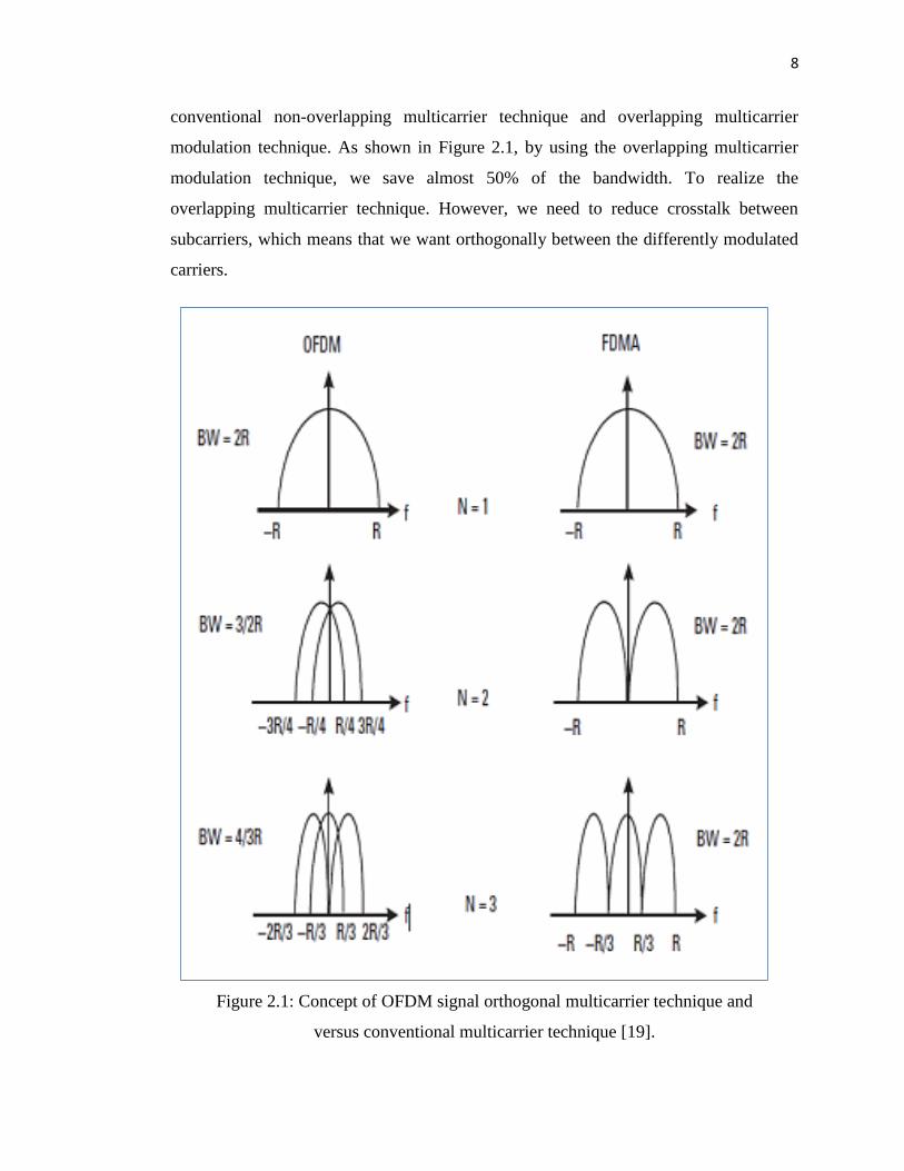
between the closely spaced carriers. Figure 2.1 shows the difference between the
8
conventional non-overlapping multicarrier technique and overlapping multicarrier
modulation technique. As shown in Figure 2.1, by using the overlapping multicarrier
modulation technique, we save almost 50% of the bandwidth. To realize the
overlapping multicarrier technique. However, we need to reduce crosstalk between
subcarriers, which means that we want orthogonally between the differently modulated
carriers.
Figure 2.1: Concept of OFDM signal orthogonal multicarrier technique and
versus conventional multicarrier technique [19].
9
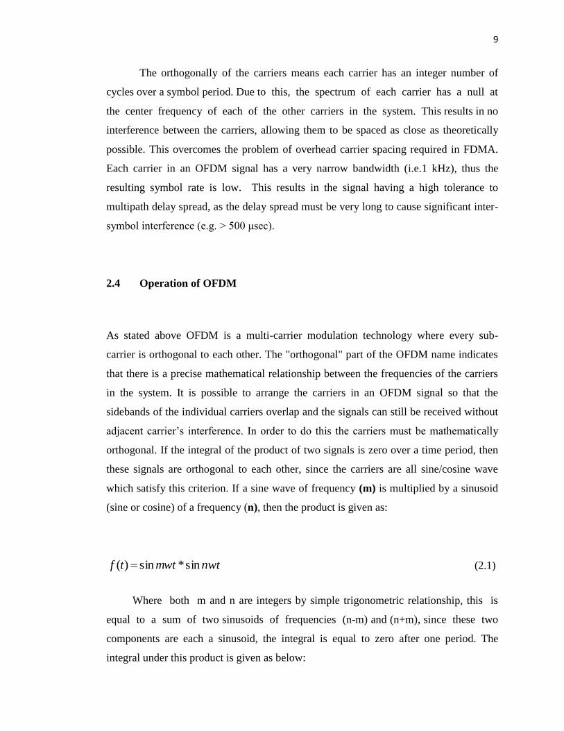
The orthogonally of the carriers means each carrier has an integer number of
cycles over a symbol period. Due to this, the spectrum of each carrier has a null at
the center frequency of each of the other carriers in the system. This results in no
interference between the carriers, allowing them to be spaced as close as theoretically
possible. This overcomes the problem of overhead carrier spacing required in FDMA.
Each carrier in an OFDM signal has a very narrow bandwidth (i.e.1 kHz), thus the
resulting symbol rate is low. This results in the signal having a high tolerance to
multipath delay spread, as the delay spread must be very long to cause significant inter-
symbol interference (e.g. > 500 μsec).
2.4 Operation of OFDM
As stated above OFDM is a multi-carrier modulation technology where every sub-
carrier is orthogonal to each other. The "orthogonal" part of the OFDM name indicates
that there is a precise mathematical relationship between the frequencies of the carriers
in the system. It is possible to arrange the carriers in an OFDM signal so that the
sidebands of the individual carriers overlap and the signals can still be received without
adjacent carrier‟s interference. In order to do this the carriers must be mathematically
orthogonal. If the integral of the product of two signals is zero over a time period, then
these signals are orthogonal to each other, since the carriers are all sine/cosine wave
which satisfy this criterion. If a sine wave of frequency (m) is multiplied by a sinusoid
(sine or cosine) of a frequency (n), then the product is given as:
nwtmwttf sin*sin)( (2.1)
Where both m and n are integers by simple trigonometric relationship, this is
equal to a sum of two sinusoids of frequencies (n-m) and (n+m), since these two
components are each a sinusoid, the integral is equal to zero after one period. The
integral under this product is given as below:
10
wtnmnmtf )cos(2
1)cos(
2
02
1)(
(2.2)
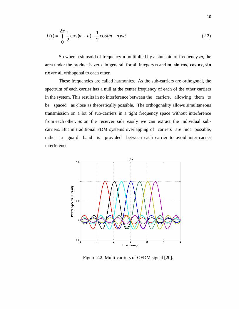
So when a sinusoid of frequency n multiplied by a sinusoid of frequency m, the
area under the product is zero. In general, for all integers n and m, sin mx, cos nx, sin
nx are all orthogonal to each other.
These frequencies are called harmonics. As the sub-carriers are orthogonal, the
spectrum of each carrier has a null at the center frequency of each of the other carriers
in the system. This results in no interference between the carriers, allowing them to
be spaced as close as theoretically possible. The orthogonality allows simultaneous
transmission on a lot of sub-carriers in a tight frequency space without interference
from each other. So on the receiver side easily we can extract the individual sub-
carriers. But in traditional FDM systems overlapping of carriers are not possible,
rather a guard band is provided between each carrier to avoid inter-carrier
interference.
Figure 2.2: Multi-carriers of OFDM signal [20].
11
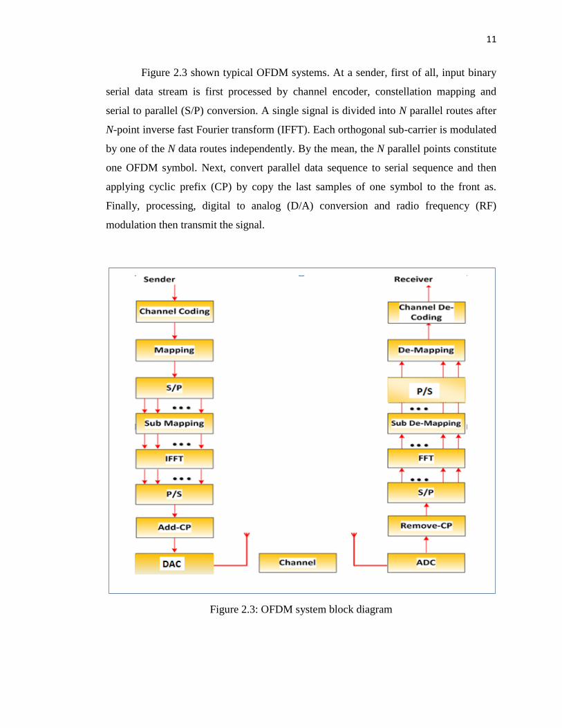
Figure 2.3 shown typical OFDM systems. At a sender, first of all, input binary
serial data stream is first processed by channel encoder, constellation mapping and
serial to parallel (S/P) conversion. A single signal is divided into N parallel routes after
N-point inverse fast Fourier transform (IFFT). Each orthogonal sub-carrier is modulated
by one of the N data routes independently. By the mean, the N parallel points constitute
one OFDM symbol. Next, convert parallel data sequence to serial sequence and then
applying cyclic prefix (CP) by copy the last samples of one symbol to the front as.
Finally, processing, digital to analog (D/A) conversion and radio frequency (RF)
modulation then transmit the signal.
Figure 2.3: OFDM system block diagram
12
At the receiver end, firstly, demodulate received signals then demodulated signals are
converted from analog to digital (A/D) converter, sample output and take time
estimation to find an initial position of OFDM symbol. The CP added in transmission
process is removed and N-Points fast Fourier transforms (FFT) transformation will be
conducted on the sample points to recover the data in the frequency domain. Finally, the
output of baseband demodulation is passed to the channel decoder to recover the
original data.
2.4.1 Multicarrier System and Single Carrier
2.4.1.1 Single Carrier System Basic Structure
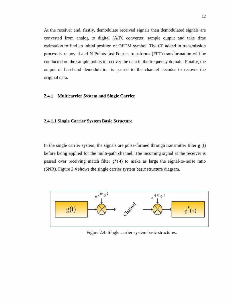
In the single carrier system, the signals are pulse-formed through transmitter filter g (t)
before being applied for the multi-path channel. The incoming signal at the receiver is
passed over receiving match filter g*(-t) to make as large the signal-to-noise ratio
(SNR). Figure 2.4 shows the single carrier system basic structure diagram.
Cha
nnel
Cha
nnel
tjωe o t-j ω
e o
g(t) (-t)*g
Figure 2.4: Single carrier system basic structures.
13
2.4.1.2 Multicarrier System Basic Structure
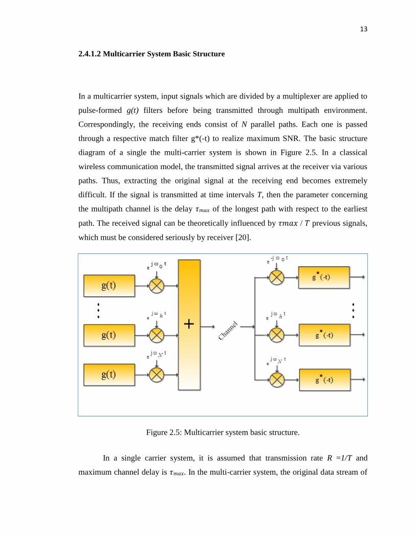
In a multicarrier system, input signals which are divided by a multiplexer are applied to
pulse-formed g(t) filters before being transmitted through multipath environment.
Correspondingly, the receiving ends consist of N parallel paths. Each one is passed
through a respective match filter g*(-t) to realize maximum SNR. The basic structure
diagram of a single the multi-carrier system is shown in Figure 2.5. In a classical
wireless communication model, the transmitted signal arrives at the receiver via various
paths. Thus, extracting the original signal at the receiving end becomes extremely
difficult. If the signal is transmitted at time intervals T, then the parameter concerning
the multipath channel is the delay 𝜏𝑚𝑎𝑥 of the longest path with respect to the earliest
path. The received signal can be theoretically influenced by 𝜏𝑚𝑎𝑥 / 𝑇 previous signals,
which must be considered seriously by receiver [20].
Figure 2.5: Multicarrier system basic structure.
In a single carrier system, it is assumed that transmission rate R =1/T and
maximum channel delay is 𝜏𝑚𝑎𝑥. In the multi-carrier system, the original data stream of
14
rate R is multiplexed into N parallel data streams with rate 𝑅𝑚𝑐=1/𝑇𝑚𝑐=R/N. Each of
the sub streams is modulated with a different sub-carriers frequency and all the data
streams are transmitted in the same band. In this case, the ISI of each sub-system
reduces to 𝜏𝑚𝑎𝑥/𝑇𝑚𝑐 =𝜏𝑚𝑎𝑥/𝑁∙𝑇. As the value of N increases, inter-symbol interference
(ISI) becoming decreases.
In a single carrier system, fading or interference can make the entire link fail.
However, in the multi-carrier system, only a small part of sub-carriers will be affected.
Error correction coding methods can be employed to correct the errors which were
happening in sub-carriers. OFDM is a special form of multicarrier modulation (MCM),
in which a signal is transmitted over a number of lower rate sub-carriers.
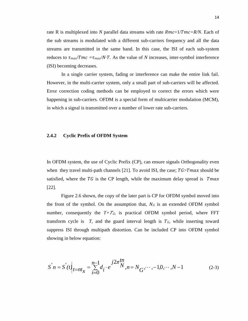
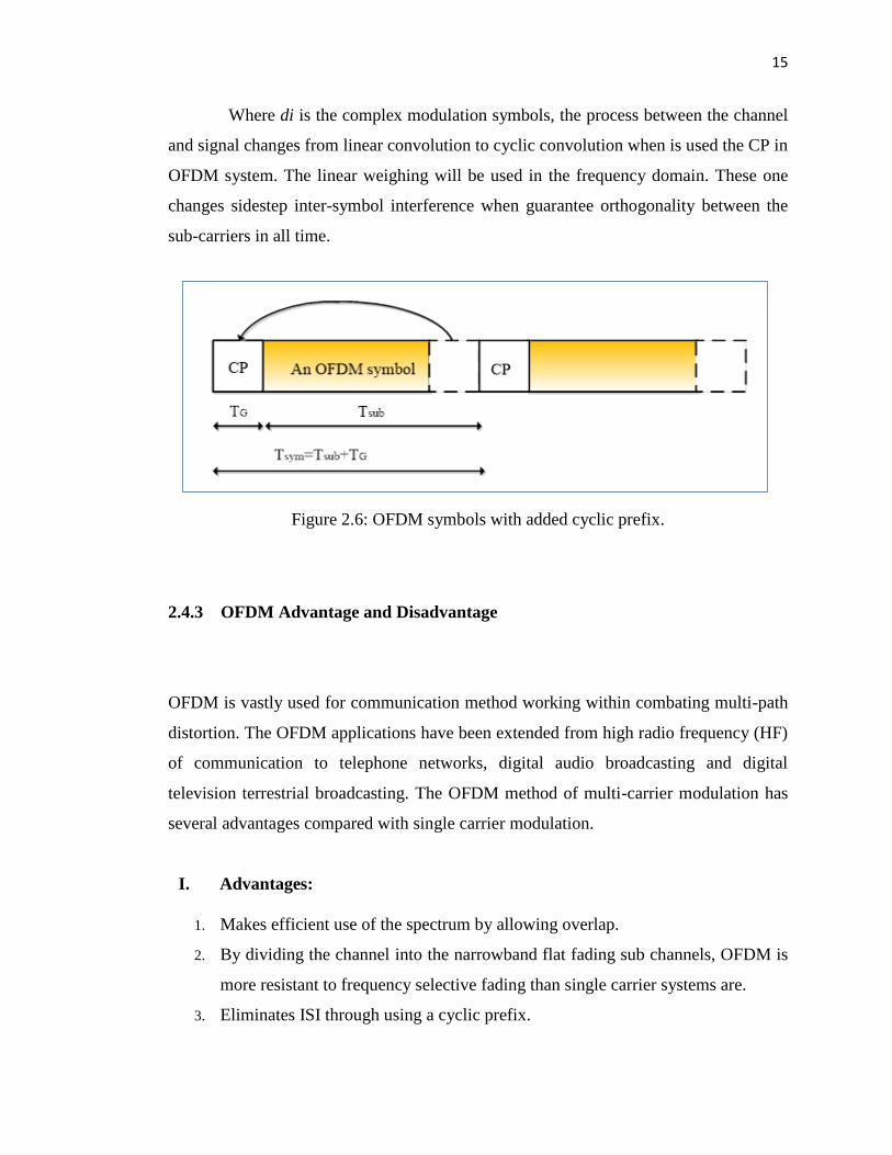
2.4.2 Cyclic Prefix of OFDM System
In OFDM system, the use of Cyclic Prefix (CP), can ensure signals Orthogonality even
when they travel multi-path channels [21]. To avoid ISI, the case; 𝑇𝐺>𝑇𝑚𝑎𝑥 should be
satisfied, where the 𝑇𝐺 is the CP length, while the maximum delay spread is 𝑇𝑚𝑎𝑥
[22].
Figure 2.6 shown, the copy of the later part is CP for OFDM symbol moved into
the front of the symbol. On the assumption that, 𝑁𝐺 is an extended OFDM symbol
number, consequently the T+𝑇𝐺, is practical OFDM symbol period, where FFT
transform cycle is T, and the guard interval length is 𝑇𝐺, while inserting toward
suppress ISI through multipath distortion. Can be included CP into OFDM symbol
showing in below equation:
10121
0
,N,,,,
GN,nN
tnπje
n
ii
dxntt(t)'Sn'S (2-3)
15
Where di is the complex modulation symbols, the process between the channel
and signal changes from linear convolution to cyclic convolution when is used the CP in
OFDM system. The linear weighing will be used in the frequency domain. These one
changes sidestep inter-symbol interference when guarantee orthogonality between the
sub-carriers in all time.
Figure 2.6: OFDM symbols with added cyclic prefix.
2.4.3 OFDM Advantage and Disadvantage
OFDM is vastly used for communication method working within combating multi-path
distortion. The OFDM applications have been extended from high radio frequency (HF)
of communication to telephone networks, digital audio broadcasting and digital
television terrestrial broadcasting. The OFDM method of multi-carrier modulation has
several advantages compared with single carrier modulation.
I. Advantages:
1. Makes efficient use of the spectrum by allowing overlap.
2. By dividing the channel into the narrowband flat fading sub channels, OFDM is
more resistant to frequency selective fading than single carrier systems are.
3. Eliminates ISI through using a cyclic prefix.
16
4. Using proper channel coding and interleaving one can recover symbols lost due
to the frequency selectivity of the channel.
5. Channel equalization becomes simpler than by using adaptive equalization
techniques with single carrier systems.
6. It is possible to use maximum likelihood decoding with reasonable complexity.
7. OFDM is computationally efficient by using FFT techniques to implement the
modulation and demodulation functions.
8. Is less sensitive to sample timing offsets than single carrier systems are.
9. Provides good protection against co-channel interference and impulsive parasitic
noise channel equalization becomes simpler than by using adaptive equalization
techniques with single carrier systems.
II. Disadvantages:
1. The OFDM signal has a noise like amplitude with a very large dynamic range.
Therefore, it requires RF power amplifiers with a high peak to average power
ratio.
2. It is more sensitive to carrier frequency offset and drift than single carrier
systems.
2.5 Peaks-to-Average Power Ratio in OFDM System
The instantaneous output of an OFDM system often has large fluctuations compared to
traditional single-carrier systems. This requires that system devices, such as power
amplifiers, A/D converters and D/A converters, must have large linear dynamic ranges.
If this is not satisfied, a series of undesirable interference is encountered when the peak
signal goes into the non-linear region of devices at the transmitter, such as high out of
band radiation and inter-modulation distortion. PAPR reduction techniques are therefore
of great importance for OFDM systems [23].
17
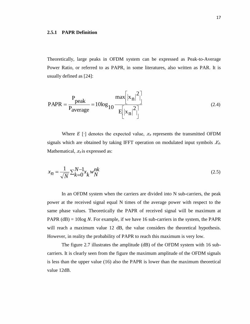
2.5.1 PAPR Definition
Theoretically, large peaks in OFDM system can be expressed as Peak-to-Average
Power Ratio, or referred to as PAPR, in some literatures, also written as PAR. It is
usually defined as [24]:
2
nxE
2nxmax
1010log
averageP
peakP
PAPR (2.4)
Where 𝐸 [∙] denotes the expected value, 𝑥𝑛 represents the transmitted OFDM
signals which are obtained by taking IFFT operation on modulated input symbols 𝑋𝑘.
Mathematical, 𝑥𝑛 is expressed as:
nkN
wNk k
xN
nx
10
1 (2.5)
In an OFDM system when the carriers are divided into N sub-carriers, the peak
power at the received signal equal N times of the average power with respect to the
same phase values. Theoretically the PAPR of received signal will be maximum at
PAPR (dB) = 10log 𝑁. For example, if we have 16 sub-carriers in the system, the PAPR
will reach a maximum value 12 dB, the value considers the theoretical hypothesis.
However, in reality the probability of PAPR to reach this maximum is very low.
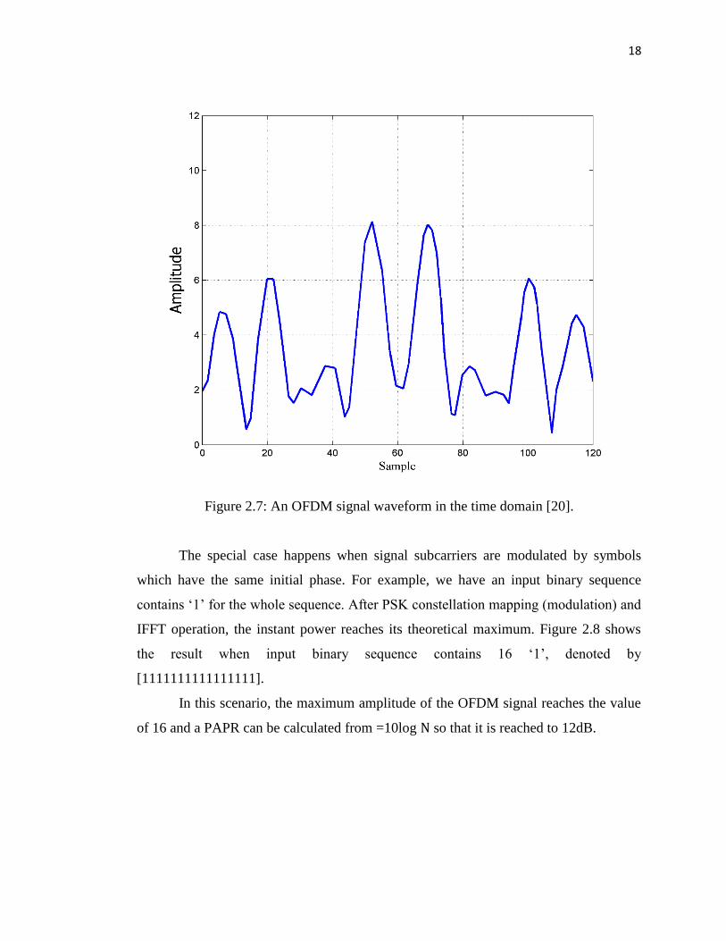
The figure 2.7 illustrates the amplitude (dB) of the OFDM system with 16 sub-
carriers. It is clearly seen from the figure the maximum amplitude of the OFDM signals
is less than the upper value (16) also the PAPR is lower than the maximum theoretical
value 12dB.
18
Figure 2.7: An OFDM signal waveform in the time domain [20].
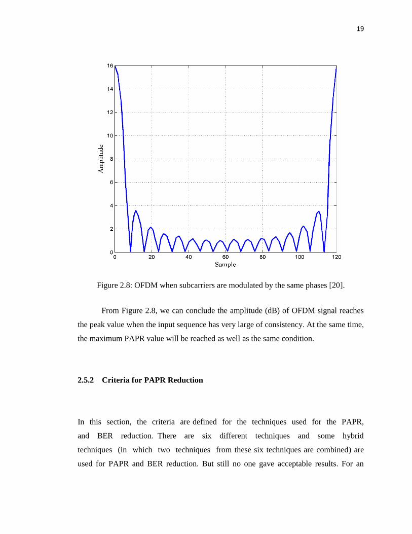
The special case happens when signal subcarriers are modulated by symbols
which have the same initial phase. For example, we have an input binary sequence
contains „1‟ for the whole sequence. After PSK constellation mapping (modulation) and
IFFT operation, the instant power reaches its theoretical maximum. Figure 2.8 shows
the result when input binary sequence contains 16 „1‟, denoted by
[1111111111111111].
In this scenario, the maximum amplitude of the OFDM signal reaches the value
of 16 and a PAPR can be calculated from =10log N so that it is reached to 12dB.
19
Figure 2.8: OFDM when subcarriers are modulated by the same phases [20].
From Figure 2.8, we can conclude the amplitude (dB) of OFDM signal reaches
the peak value when the input sequence has very large of consistency. At the same time,
the maximum PAPR value will be reached as well as the same condition.
2.5.2 Criteria for PAPR Reduction
In this section, the criteria are defined for the techniques used for the PAPR,
and BER reduction. There are six different techniques and some hybrid
techniques (in which two techniques from these six techniques are combined) are
used for PAPR and BER reduction. But still no one gave acceptable results. For an
20
acceptable technique, that technique must reduce the PAPR and BER largely plus the
following performance factors must be considered for OFDM based system.
2.5.2.1 Capability of PAPR Reduction
The primary factor of selecting PAPR reduction technique is the capability of PAPR
reduction. A technique is considered best if it reduces PAPR largely. Out Of Band
radiation (OOB) and In Band (IB) distortion are few considerable factors for selecting a
technique
2.5.2.2 Low Average Power
A technique must reduce PAPR as well as the average power of the signal not increased
from an acceptable region. If so it will require a large linear region for operation
in High Power Amplifier (HPA), which will increase the BER rate of the OFDM
system.
2.5.2.3 Low Complexity
The technique should also not increase the complexity of the overall system.
Complexity includes both time and hardware requirements for implementation of the
system.
21
2.5.2.4 Less Bandwidth Expansion
Some techniques such as scrambling techniques need side information, which increase
the bandwidth usage. Some coding techniques also expand the bandwidth due to code
rate generation. A technique must not increase the bandwidth in value which
causes degradation in the throughput.
2.5.2.5 Less BER Performance Degradation
The main goal of the PAPR reduction technique is to gain better performance, including
BER as compared to the conventional OFDM system.
2.5.2.6 Less Additional Power Need
The technique required no additional power for PAPR reduction, as it will
degrade the BER performance of the system plus power efficiency is the main goal of
wireless based systems.
2.5.2.7 Good Spectral Efficiency
If a technique destroys the ICI or immunity to multipath fading or some other advantage
related to spectrum should not be considered a good PAPR reduction technique.
22
2.6 Probability Distribution Function of PAPR
In accordance to the centric limit theorem, for sub-carriers great number in multi-carrier
signal, the sample values real and imaginary part in time-domain will obey Gaussian
distribution with mean 0 and variance of 0.5 average values. For that, the multi-carrier
signals amplitude follows Rayleigh distribution with zero average and N times
difference, and the one complex sinusoid difference [25]. Its power value comply the
𝜒2 distribution with zero average and freedom 2 degrees. The Cumulative Distribution
Function (CDF) written as follows:
)exp(1)( zzF (2-6)
On the assumption that the different sub-channels, sampling values are
reciprocally freelance, and free for oversampling operation, the PAPR probability
distribution function less than the confirmed threshold value, then equation written as
follows:
NzNzFzPAPRP ))exp(1()()( < (2-7)
PAPR in reality it favored to take into account the probability exceeding and the
index measuring the threshold for a representation of the distribution of PAPR. Thus, it
can be called as a “Complementary Cumulative Distribution Function” (CCDF), and is
written as:
NzNzFzPAPRPzPAPRP ))exp(1(1)(1)(1)( (2-8)
23
2.7 Studying of PAPR Reduction Techniques
There are many different algorithms that have been proposed to solve the high PAPR
problem of OFDM system. These reduction solutions can be roughly divided into three
categories:
2.7.1 Signal Scrambling Methods
The essential precept of this method is to scramble every OFDM signal with various
scrambling sequences while it‟s smallest for transmission of PAPR value. Obviously,
this method does not ensure that to decrease the value of PAPR lower to a certain
threshold, but it can decrease the high PAPR appearance probability to a great range.
Thus, this approach type implicates, firstly the Selective Mapping SLM and then the
Partial Transmit Sequences PTS. Appling scrambling rotation of SLM technique to all
sub-carriers autonomously, but scrambling of PTS technique applied to the part of sub-
carriers. The two techniques can be considered to apply each scenario without
constraint within sub-carriers number and modulation type. Nevertheless, in order to
indicate the successful recovery at the receiver, additional information is needed. That
leads to the use of low-bandwidth and high-complexity hardware implementation.
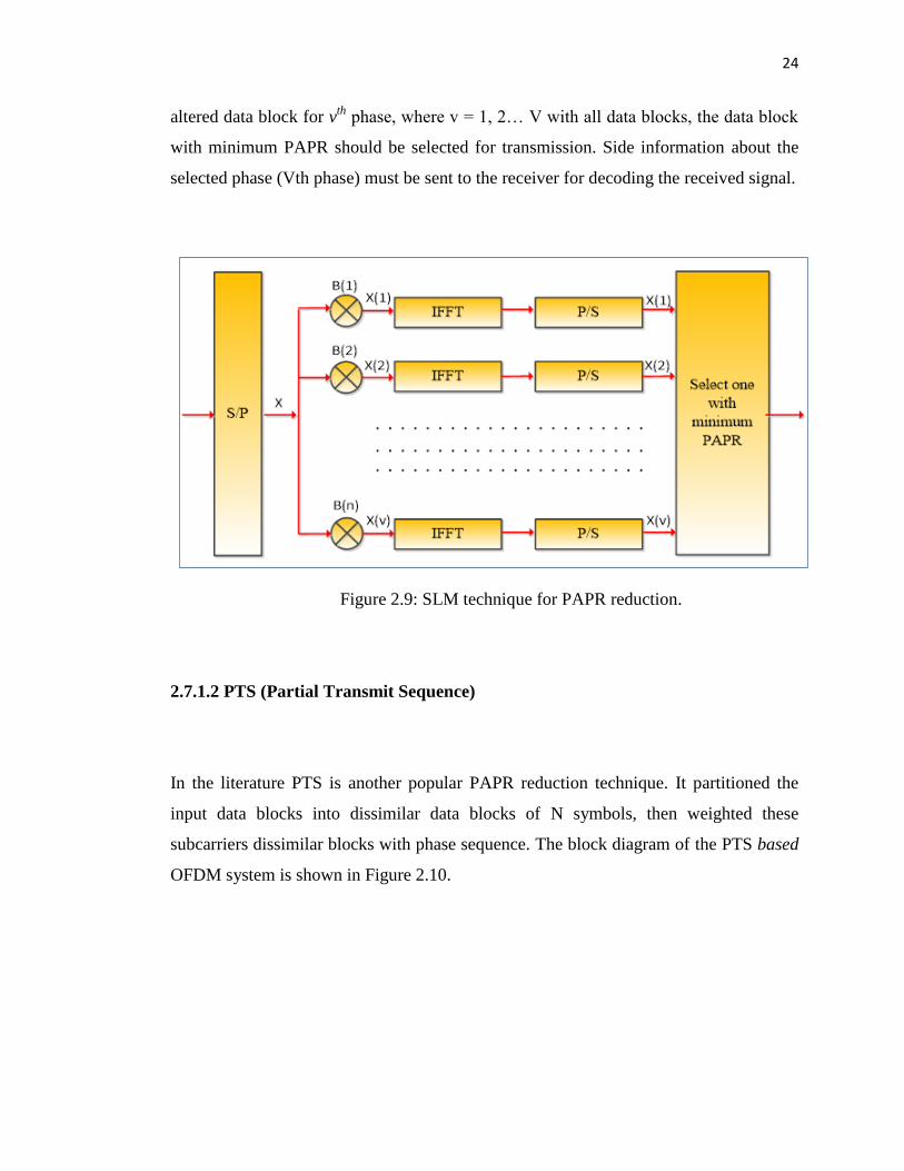
2.7.1.1 SLM Selective Mapping
A set of V dissimilar data blocks is created at the receiver side which consist identical
information and a block with minimum PAPR is selected for transmission. This
technique is used in SLM which is shown in Figure 2.9, multiplied with the dissimilar
phase sequence V of length N. (v=1, 2, …V) results an altered data block. Let‟s an
24
altered data block for vth
phase, where v = 1, 2… V with all data blocks, the data block
with minimum PAPR should be selected for transmission. Side information about the
selected phase (Vth phase) must be sent to the receiver for decoding the received signal.
Figure 2.9: SLM technique for PAPR reduction.
2.7.1.2 PTS (Partial Transmit Sequence)
In the literature PTS is another popular PAPR reduction technique. It partitioned the
input data blocks into dissimilar data blocks of N symbols, then weighted these
subcarriers dissimilar blocks with phase sequence. The block diagram of the PTS based
OFDM system is shown in Figure 2.10.
27
REFERENCES
[1] K. Srinivasarao, B. Prabhakararao, and M. Sairam, "PEAK-TO-AVERAGE
POWER REDUCTION IN MIMO-OFDM SYSTEMS USING SUB-
OPTIMAL ALGORITHM," International Journal of Distributed & Parallel
Systems, vol. 3, 2012.
[2] K. Young Kyun and R. Prasad, "4G Roadmap and Emerging Communication
Technologies. Artech House," ISBN 1-58053-931-9.
[3] J. Hou, J. Ge, D. Zhai, and J. Li, "Peak-to-average power ratio reduction of
OFDM signals with nonlinear companding scheme," Broadcasting, IEEE
Transactions on, vol. 56, pp. 259-263, 2010.
[4] I. Baig and V. Jeoti, "DCT precoded Selective Mapping technique for PAPR
reduction in OFDM systems," in Intelligent and Advanced Systems (ICIAS),
2010 International Conference on, 2010, pp. 1-6.
[5] C.-P. Li, S.-H. Wang, and C.-L. Wang, "Novel low-complexity SLM schemes
for PAPR reduction in OFDM systems," Signal Processing, IEEE
Transactions on, vol. 58, pp. 2916-2921, 2010.
[6] X. Ouyang, J. Jin, and Z. Wang, "A low complexity peak-to-average power
ratio reduction method for OFDM systems," in Communications and
Networking in China (CHINACOM), 2011 6th International ICST Conference
on, 2011, pp. 114-117.
[7] M. Naeiny and F. Marvasti, "Selected Mapping Algorithm for PAPR reduction
of space-frequency coded OFDM systems without side information,"
Vehicular Technology, IEEE Transactions on, vol. 60, pp. 1211-1216, 2011.
[8] I. Baig and V. Jeoti, "On the PAPR reduction in OFDM systems: a novel ZCT
precoding based SLM technique," Journal of Engineering Science and
Technology, vol. 6, pp. 266-378, 2011.
27
[9] J. Hou, J. Ge, and J. Li, "Peak-to-average power ratio reduction of OFDM
signals using PTS scheme with low computational complexity," Broadcasting,
IEEE Transactions on, vol. 57, pp. 143-148, 2011.
[10] D. Guel and J. Palicot, "FFT/IFFT pair based digital filtering for the
transformation of adding signal PAPR reduction techniques in tone reservation
techniques," in Wireless and Mobile Communications, 2009. ICWMC'09. Fifth
International Conference on, 2009, pp. 200-204.
[11] D.Guel, J. Palicot, and Y. Louët, "Tone reservation technique based on
geometric method for orthogonal frequency division multiplexing peak-to-
average power ratio reduction," IET communications, vol. 4, pp. 2065-2073,
2010.
[12] S. B. Weinstein, "The history of orthogonal frequency-division multiplexing
[History of Communications]," Communications Magazine, IEEE, vol. 47, pp.
26-35, 2009.
[13] N. J. LaSorte, W. J. Barnes, and H. H. Refai, "The History of Orthogonal
Frequency Division Multiplexing," in GLOBECOM, 2008, pp. 3592-3596.
[14] C. Ciochina and H. Sari, "A review of OFDMA and single-carrier FDMA," in
Wireless Conference (EW), 2010 European, 2010, pp. 706-710.
[15] A. Peled and A. Ruiz, "Frequency domain data transmission using reduced
computational complexity algorithms," in Acoustics, Speech, and Signal
Processing, IEEE International Conference on ICASSP'80., 1980, pp. 964-
967.
[16] L. J. Cimini, "Analysis and simulation of a digital mobile channel using
orthogonal frequency division multiplexing," Communications, IEEE
Transactions on, vol. 33, pp. 665-675, 1985.
[17] E. Panayirci, H. Senol, and H. V. Poor, "Joint channel estimation, equalization,
and data detection for OFDM systems in the presence of very high mobility,"
Signal Processing, IEEE Transactions on, vol. 58, pp. 4225-4238, 2010.
27
[18] M. Ergen, "Principles of OFDM," in Mobile Broadband, ed: Springer, 2009,
pp. 109-175.
[19] U. S. Jha and R. Prasad, OFDM towards fixed and mobile broadband wireless
access: Artech House, Inc., 2007.
[20] N. Kaneda, Q. Yang, X. Liu, S. Chandrasekhar, W. Shieh, and Y.-K. Chen,
"Real-time 2.5 GS/s coherent optical receiver for 53.3-Gb/s sub-banded
OFDM," Journal of lightwave technology, vol. 28, pp. 494-501, 2010.
[21] D. Qu, Z. Wang, and T. Jiang, "Extended active interference cancellation for
sidelobe suppression in cognitive radio OFDM systems with cyclic prefix,"
Vehicular Technology, IEEE Transactions on, vol. 59, pp. 1689-1695, 2010.
[22] K. Nagatomi, H. Kawai, and K. Higuchi, "Complexity-reduced MLD based on
QR decomposition in OFDM MIMO multiplexing with frequency domain
spreading and code multiplexing," EURASIP Journal on Advances in Signal
Processing, vol. 2011, p. 5, 2011.
[23] P. Variorum, W. F. Al-Azzo, and B. M. Ali, "A low complexity partial transmit
sequence scheme by use of dummy signals for PAPR reduction in OFDM
systems," Consumer Electronics, IEEE Transactions on, vol. 56, pp. 2416-
2420, 2010.
[24] Y. Wang, W. Chen, and C. Tellambura, "A PAPR reduction method based on
artificial bee colony algorithm for OFDM signals," Wireless Communications,
IEEE Transactions on, vol. 9, pp. 2994-2999, 2010.
[25] B. Farhang-Boroujeny and C. H. Yuen, "Cosine modulated and offset QAM
filter bank multicarrier techniques: a continuous-time prospect," EURASIP
Journal on Advances in Signal Processing, vol. 2010, p. 6, 2010.
[26] J. Hou, J. Ge, D. Zhai, and J. Li, "Peak-to-average power ratio reduction of
OFDM signals with nonlinear companding scheme," Broadcasting, IEEE
Transactions on, vol. 56, pp. 258-262, 2010.
27
[27] M. Sabbaghian, Y. Kwak, B. Smida, and V. Tarokh, "Near Shannon limit and
low peak to average power ratio turbo block coded OFDM," Communications,
IEEE Transactions on, vol. 59, pp. 2042-2045, 2011.
[28] J. Hou, J. Ge, and J. Li, "Peak-to-average power ratio reduction of OFDM
signals using PTS scheme with low computational complexity," Broadcasting,
IEEE Transactions on, vol. 57, pp. 145-149, 2011.
[29] C.-P.Li, S.-H.Wang, and C.-L. Wang, "Novel low-complexity Selective
mapping schemes for PAPR reduction in OFDM systems," Signal Processing,
IEEE Transactions on, vol. 58, pp. 2916-2921, 2010.
[30] I. Baig and V. Jeoti, "PAPR reduction in OFDM systems: Zadoff-Chu matrix
transform based pre/post-coding techniques," in Computational Intelligence,
Communication Systems and Networks (CICSyN), 2010 Second International
Conference on, 2010, pp. 373-377.
[31] H.-L. Hung, "Using evolutionary computation technique for trade-off between
performance peak-to average power ration reduction and computational
complexity in OFDM systems," Computers & Electrical Engineering, vol. 37,
pp. 57-70, 2011.
[32] H.-L. Hung and Y.-F. Huang, "Peak-to-average power ratio reduction in
orthogonal frequency division multiplexing system using differential
evolution-based partial transmit sequences scheme," Communications, IET,
vol. 6, pp. 1483-1488, 2012.
[33] J.-C. Chen, "Partial transmit sequences for PAPR reduction of OFDM signals
with stochastic optimization techniques," Consumer Electronics, IEEE
Transactions on, vol. 56, pp. 1229-1234, 2010.
[34] N. Taspinar, A. Kalinli, and M. Yildirim, "Partial transmit sequences for PAPR
reduction using parallel tabu search algorithm in OFDM systems,"
Communications Letters, IEEE, vol. 15, pp. 974-976, 2011.
[35] L. Wang and J. Liu, "PAPR reduction of OFDM signals by PTS with grouping
and recursive phase weighting methods," Broadcasting, IEEE Transactions
on, vol. 57, pp. 299-306, 2011.
27
[36] Hyun-Seung Joo, Jong-Seon No," A New Subblock Partitioning Scheme Using
Sub block Partition Matrix for PTS", Broadcasting, IEEE Transactionson ,
International Conference on, 2011, pp. 127 – 128.
[37] J.-C. Chen, "Application of quantum-inspired evolutionary algorithm to reduce
PAPR of an OFDM signal using partial transmit sequences technique,"
Broadcasting, IEEE Transactions on, vol. 56, pp. 110-113, 2010.
[38] L. Hsinying,C. Houshou and W. Chao-Ming. 2009. A modified partial transmit
sequence with PAPR reduction and error correction in 16-QA OFDM systems.
In: Intelligent Signal Processing and Communications Systems, 2008.
ISPACS2008, International Symposium on. pp. 1-4.
[39] L. Wang and J. Liu, "PAPR reduction of OFDM signals by Partial transmit
sequance with grouping and recursive phase weighting methods,"
Broadcasting, IEEE Transactions on, vol. 57, pp. 299-306, 2011.
[40] A. Goel, P. Gupta and M. Agrawal. 2012. SER analysis of Partial transmit
sequance based techniques for PAPR reduction in OFDM systems. Digital
Signal Processing.