Embed Size (px)
Citation preview
RisB-R=1257(EN)
Isolated Systems with Wind Power
An Implementation Guideline
Niels-Erik Clausen, Henrik Bindner, Sten Frandsen,Jens Carsten Hansen, Lars Henrik Hansen, Per Lundsager
Risa National Laboratory, Roskilde, DenmarkJune 2001
Abstract The overall objective of this research project is to study the devel-opment of methods and guidelines rather than “universal solutions” for the useof wind energy in isolated communities. So far most studies of isolated systemswith wind power have been case-oriented and it has proven difficult to extendresults from one project to another, not least due to the strong individuality thathas characterised such systems in design and implementation.
In the present report a unified and generally applicable approach is attempted inorder to support a fair assessment of the technical and economical feasibility ofisolated power supply systems with wind energy.
General guidelines and checklists on which facts and data are needed to carryout a project feasibility analysis are presented as well as guidelines how to carryout the project feasibility study and the environmental analysis.
The report outlines the results of the project as a set of proposed guidelines tobe applied when developing a project containing an application of wind in anisolated power system. It is the author’s hope that this will facilitate the devel-opment of projects and enhance electrification of small rural communities indeveloping countries.
ISBN 87-550-2860-8; ISBN 87-550 -2861-6 (internet)ISSN 0106-2840
Print: Danka Services International, 2001
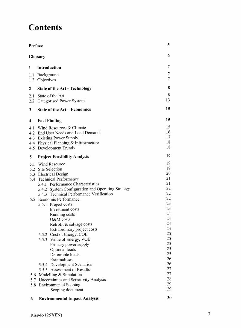
Contents
Preface
Glossary
1 Introduction
1.1 Background1.2 Objectives
2 State of the Art - Technology
2.1 State of the Art2.2 Categorised Power Systems
3 State of the Art – Economics
4 Fact Finding
4.1 Wind Resources & Climate4.2 End User Needs and Load Demand4.3 Existing Power Supply4.4 Physical Planning & Infrastructure4.5 Development Trends
5 Project Feasibility Analysis
5.1 Wind Resource5.2 Site Selection5.3 Electrical Design5.4 Technical Performance
5.4.1 Performance Characteristics5.4.2 System Configuration and Operating Strategy5.4.3 Technical Performance Verification
5.5 Economic Performance5.5.1 Project costs
Investment costsRunning costsO&M costsRetrofit & salvage costsExtraordinary project costs
5.5.2 Cost of Energy, COE5.5.3 Value of Energy, VOE
Primary power sUpplyOptional loadsDeferrable loadsExternalities
5.5.4 Development Scenarios5.5.5 Assessment of Results
5.6 Modelling & Simulation5.7 Uncertainties and Sensitivity Analysis5.8 Environmental Scoping
Scoping document
6 Environmental Impact Analysis
Riso-R-1257(EN)
5
6
7
77
8
813
15
15
1516171818
19
1919202121222222232324242424252525252526262727282929
30
61.62.63.64.65.
7
71.72.73.74.75.
8
9
10
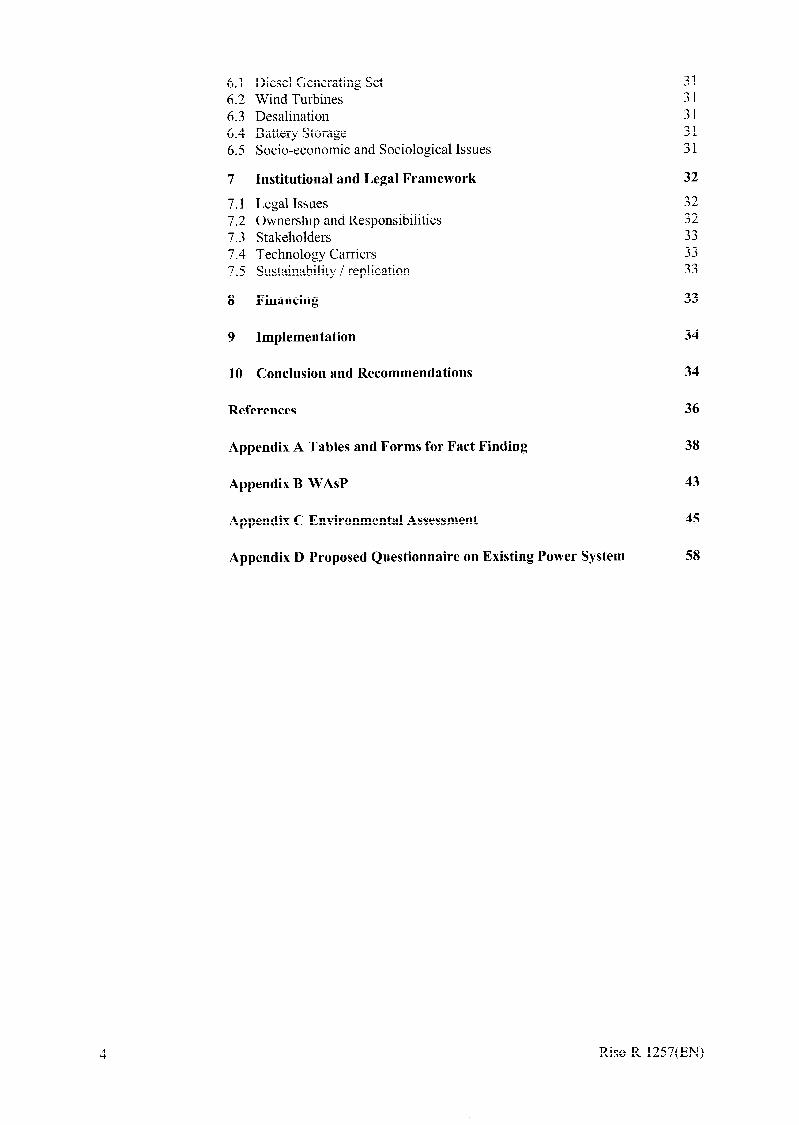
Diesel Generating SetWind TurbinesDesalinationBattery StorageSocio-economic and Sociological Issues
Institutional and Legal Framework
Legal IssuesOwnership and ResponsibilitiesStakeholdersTechnology CarriersSustainability / replication
Financing
Implementation
Conclusion and Recommendations
References
Appendix A Tables and Forms for Fact Finding
Appendix B WASP
Appendix C Environmental Assessment
Appendix D Proposed Questionnaire on Existing Power System
3131313131
32
3232333333
33
34
34
36
38
43
45
58
Riso-R-1257(EN)
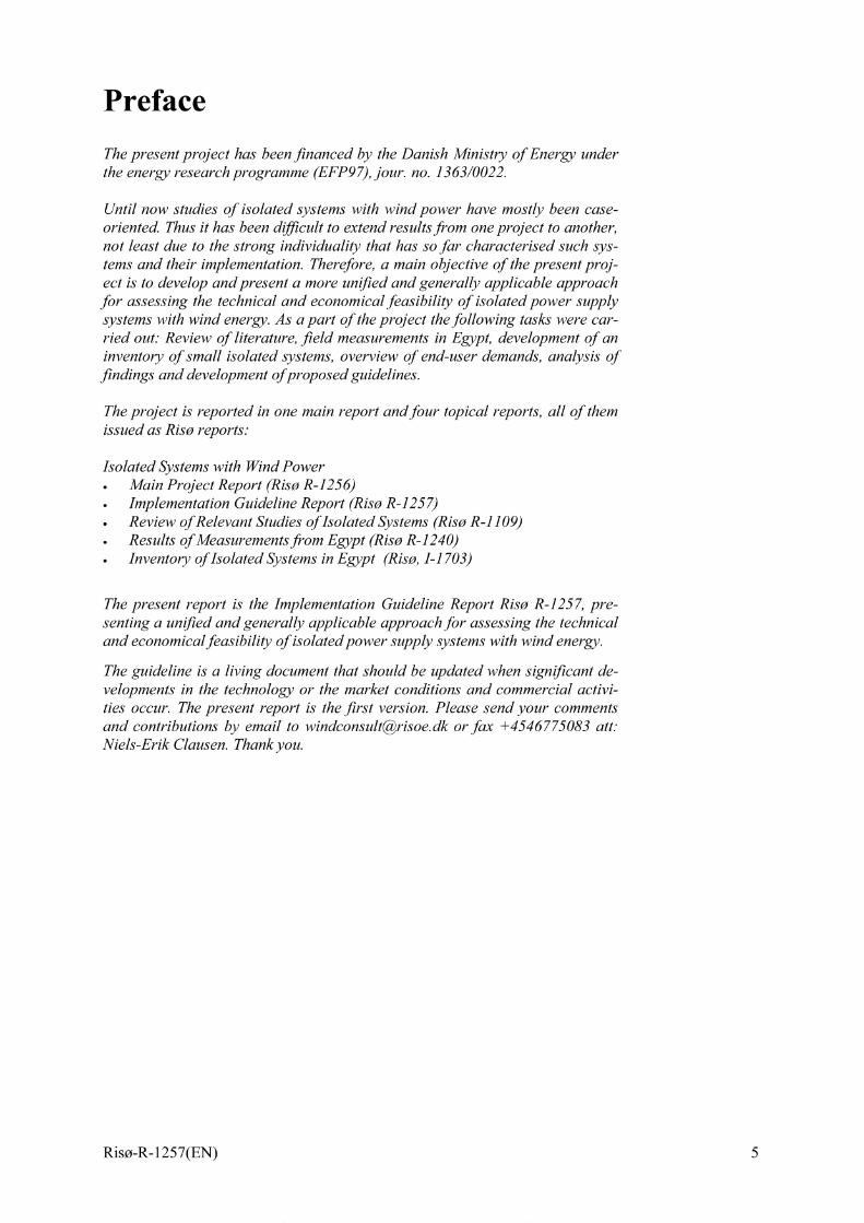
Preface
The present project has been Jnanced by the Danish Ministy of Energy underthe energy research programne (EFP97), jour. no. 1363/0022.
Until now studies of isolated systems with wind power have mostly been case-oriented. Thus it has been djjjcult to extend resultsfrom one project to another,not least due to the strong individuality that has so far characterised such sys-tems and their implementation. Therefore, a main objective of the present proj-ect is to develop andpresent a more unij?edand generally applicable approachfor assessing the technical and economical feasibility of isolated power supplysystems with wind energy. As apart of theproj”ect thefollowing tasks were car-ried out: Review of literature, Jeld measurements in Egypt, development of aninventoy of small isolated systems, overview of end-user demands, analysis ofjindings and development ofproposedguidelines.
The project is reported in one main report andfour topical reports, all of themissued as Riso reports.”
Isolated Systemswith WindPower. Main Project Report (Riso R-1256)● Implementation Guideline Report (Riso R-1257). Review of Relevant Studies of Isolated Systems (Riso R-1109). Results of Measurementsfrom Egypt (Riso R-1240). Inventoy of Isolated Systems in Egypt (Rise, I-1703)
The present report is the Implementation Guideline Report Riso R-1257, pre-senting a unij?ed and generally applicable approach for assessing the technicaland economical feasibility of isolated power supply systems with wind energy.
The guideline is a living document that should be updated when signij?cant de-velopments in the technology or the market conditions and commercial activi-ties occur. The present report is the Jrst version. Please send your commentsand contributions by email to windconsult@risoe. dk or fax +4546775083 att:lViels-Erik Clausen. Thankyou.
Riso-R-1257(EN)
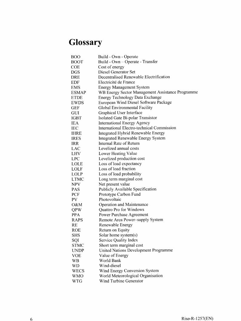
BOOBOOTCOEDGSDREEDFEMSESMAPETDEEWDSGEFGUIIGBTIEAIECIHREIRESIRRLACLHVLPCLOLELOLFLOLPLTMCNPVPASPCFPvO&MQPWPPARAPSREROESHSSQISTMCUNDPVOEWBWDWECSWMOWTG
Build - Own - OperateBuild - Own – OperateCost of energyDiesel Generator Set
Transfer
Decentralised Renewable ElectrificationElectricity de FranceEnergy Management SystemWB Energy Sector Management Assistance ProgrammeEnergy Technology Data ExchangeEuropean Wind Diesel Software PackageGlobal Environmental FacilityGraphical User InterfaceIsolated Gate Bi-polar TransistorInternational Energy AgencyInternational Electro-technical CommissionIntegrated Hybrid Renewable EnergyIntegrated Renewable Energy SystemInternal Rate of ReturnLevelized annual costsLower Heating ValueLevelized production costLoss of load expectancyLoss of load fractionLoss of load probabilityLong term marginal costNet present valuePublicly Available SpecificationPrototype Carbon FundPhotovoltaicOperation and MaintenanceQuattro Pro for WindowsPower Purchase AgreementRemote Area Power–supply SystemRenewable EnergyReturn on EquitySolar home system(s)Service Quality IndexShort term marginal costUnited Nations Development ProgrammeValue of EnergyWorld BankWind-dieselWind Energy Conversion SystemWorld Meteorological OrganisationWind Turbine Generator
6 RisO-R-1257(EN)
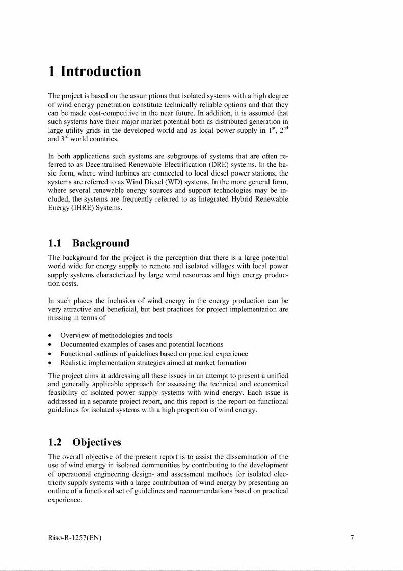
1 Introduction
The project is based on the assumptions that isolated systems with a high degreeof wind energy penetration constitute technically reliable options and that theycan be made cost-competitive in the near fbture. In addition, it is assumed thatsuch systems have their major market potential both as distributed generation inlarge utility grids in the developed world and as local power supply in Ist, 2ndand 3rdworld countries.
In both applications such systems are subgroups of systems that are often re-ferred to as Decentralised Renewable Electrification (DRE) systems. In the ba-sic form, where wind turbines are connected to local diesel power stations, thesystems are referred to as Wind Diesel (WD) systems. In the more general form,where several renewable energy sources and support technologies may be in-cluded, the systems are frequently referred to as Integrated Hybrid RenewableEnergy (IHRE) Systems.
1.1 BackgroundThe background for the project is the perception that there is a large potentialworld wide for energy supply to remote and isolated villages with local powersupply systems characterized by large wind resources and high energy produc-tion costs.
In such places the inclusion of wind energy in the energy production can bevery attractive and beneficial, but best practices for project implementation aremissing in terms of
. Overview of methodologies and tools
. Documented examples of cases and potential locations
. Functional outlines of guidelines based on practical experience
. Realistic implementation strategies aimed at market formation
The project aims at addressing all these issues in an attempt to present a unifiedand generally applicable approach for assessing the technical and economicalfeasibility of isolated power supply systems with wind energy. Each issue isaddressed in a separate project report, and this report is the report on fictionalguidelines for isolated systems with a high proportion of wind energy.
1.2 ObjectivesThe overall objective of the present report is to assist the dissemination of theuse of wind energy in isolated communities by contributing to the developmentof operational engineering design- and assessment methods for isolated elec-tricity supply systems with a large contribution of wind energy by presenting anoutline of a functional set of guidelines and recommendations based on practicalexperience.
Riso-R-1257(EN)
The difference between guidelines and standards is illustrated by the two typesof documents, that are now being developed in the framework of the IEC:
Guidelines deal with project implementation related elements of DRE systemsand may include guidelines for system selection, bid and contract, quality assur-ance, operation, maintenance and overall system classification. Several versionsof project implementation guidelines may be envisaged for various types andclasses of systems
Standards deal with the specific technical elements of DRE systems and is theresponsibility of individual technical committees in the national and interna-tional standardisation framework, that include IEC, CENELEC and other bod-ies. The standards are unique, and all project implementation guidelines shouldrefer to one and the same set of RE systems standards
These definitions are adopted in the development of IEC/PAS 62111 document(EDF, 1997) for small DRE systems for rural electrification in 3rd world coun-tries.
A basic philosophy of the presented work is that wind energy should only beintroduced in power systems when it is applicable and beneficial, rather thanintroducing wind power for demonstration purposes in projects not well suitedfor wind energy.
2 State of the Art - Technology
The main purpose of the first part of this section is to uncover “state of the art”from a technical point of view. The second part sets up a framework on how tocharacterise power systems with wind energy.
2.1 State of the ArtThe main focus of this paragraph is on state-of-the-art of wind turbines andpower systems with wind power. Since the technical know-how and perform-ance of wind tirbines are non-uniform a definition for categorisation of windturbines will be introduced. Power systems with wind power are assessed byliterature.
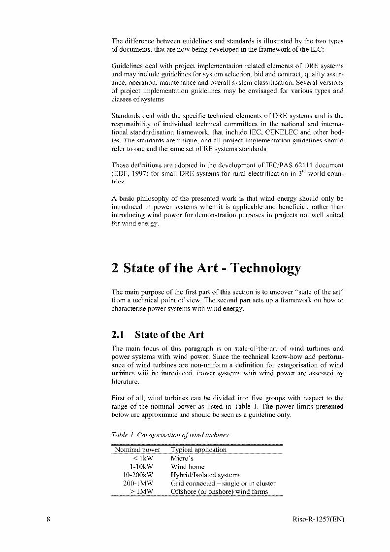
First of all, wind tirbines can be divided into five groups with respect to therange of the nominal power as listed in Table 1. The power limits presentedbelow are approximate and should be seen as a guideline only.
Table 1. Categorisation of wind turbines.
Nominal power Typical application
< lkW Micro’sl-10kW Wind home
10-200kW Hybrid/Isolated systems200-lMW Grid connected – single or in cluster
> lMW Offshore (or onshore) wind farms
8 Riso-R-1257(EN)
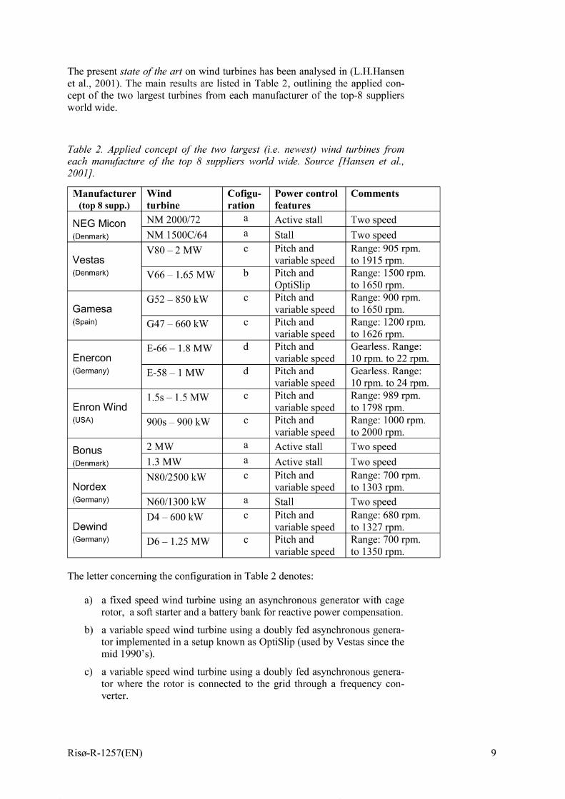
The present state of the art on wind tirbines has been analysed in (L. H. Hansenet al., 2001). The main results are listed in Table 2, outlining the applied con-cept of the two largest turbines from each manufacturer of the top-8 suppliersworld wide.
Table 2. Applied concept of the two largest (i.e. newes~ wind turbines fromeach manufacture of the top 8 suppliers world wide. Source [Hansen et al.,2001].
Manufacturer Wind co figu- Power control Comments(top 8 S1.lpp.) turbine ration features
NEG Micon NM 2000/72 a Active stall Two speed
(Denmark) NM 1500C/64 a Stall Two speed
V80 – 2 MW c Pitch and Range: 905 rpm.Vestas variable speed to 1915 rpm.(Denmark) V66 – 1.65 MW b Pitch and Range: 1500 rpm.
OptiSlip to 1650 rpm.
G52 – 850 kW c Pitch and Range: 900 rpm.Gamesa variable speed to 1650 rpm.(Spain) G47 – 660 kW c Pitch and Range: 1200 rpm.
variable speed to 1626 rpm.
E-66 – 1.8 MW d Pitch and Gearless. Range:Enercon variable speed 10 rpm. to 22 rpm.(Germany) E-58 – 1 MW d Pitch and Gearless. Range:
variable speed 10 rpm. to 24 rpm.
1.5s–1.5MW c Pitch and Range: 989 rpm.Enron Wind variable speed to 1798 rpm.(USA) 900s – 900 kW c Pitch and Range: 1000 rpm.
variable speed to 2000 rpm.
Bonus 2 MW a Active stall Two speed
(Denmark) 1.3 MW a Active stall Two speed
N80/2500 kW c Pitch and Range: 700 rpm.Nordex variable speed to 1303 rpm.(Germany) N60/1300 kW a Stall Two speed
D4 – 600 kW c Pitch and Range: 680 rpm.Dewind variable speed to 1327 rpm.(Germany) D6 – 1.25 MW c Pitch and Range: 700 rpm.
variable speed to 1350 rpm.
The letter concerning the configuration in Table 2 denotes:
a)
b)
c)
a fixed speed wind tirbine using an asynchronous generator with cagerotor, a soft starter and a batte~ bank for reactive power compensation.
a variable speed wind tirbine using a doubly fed asynchronous genera-tor implemented in a setup known as OptiSlip (used by Vestas since themid 1990’s).
a variable speed wind tirbine using a doubly fed asynchronous genera-tor where the rotor is connected to the grid through a frequency con-verter.
Riso-R-1257(EN)
d)
Based
a gearless variable speed wind turbine using a multipole wound syn-chronous generator, where the stator is connected to the grid through afrequency converter and the rotor through a rectifier.
on the findings in [Hansen et al., 20011, the present “state-of-the-art”large wind turbine is ~ 3 bladed upstream machine with tibular tower using:
● active stall with a two speed asynchronous generator, or
. pitch control combined with variable speed. Moreover, the variable speedconcept is mainly realised using configuration “c”, i.e. a doubly fed induc-tion generator with a rotor connected IGBT based frequency converter.
. only one of the top-10 manufactures is building a gearless (variable speed)wind turbine.
The above characteristics are for a typical main-stream wind turbine. Besidesthat a number of alternative wind tirbine designs exist. As described in(L.H.Hansen et al., 2001) Lagerwey is using configuration “d”, but with a 6phased wound synchronous generator. Nordic Windpower promotes configura-tion “a” in a two bladed upwind version. And Gaia is using configuration “a” ina two bladed downwind version. Vergnet is also using configuration “a”, in atwo bladed as both upwind or downwind versions. Scanwind has started theconstruction of a wind tirbine using a configuration with a permanent magnetsynchronous generator based on the Windformer and a DC grid.
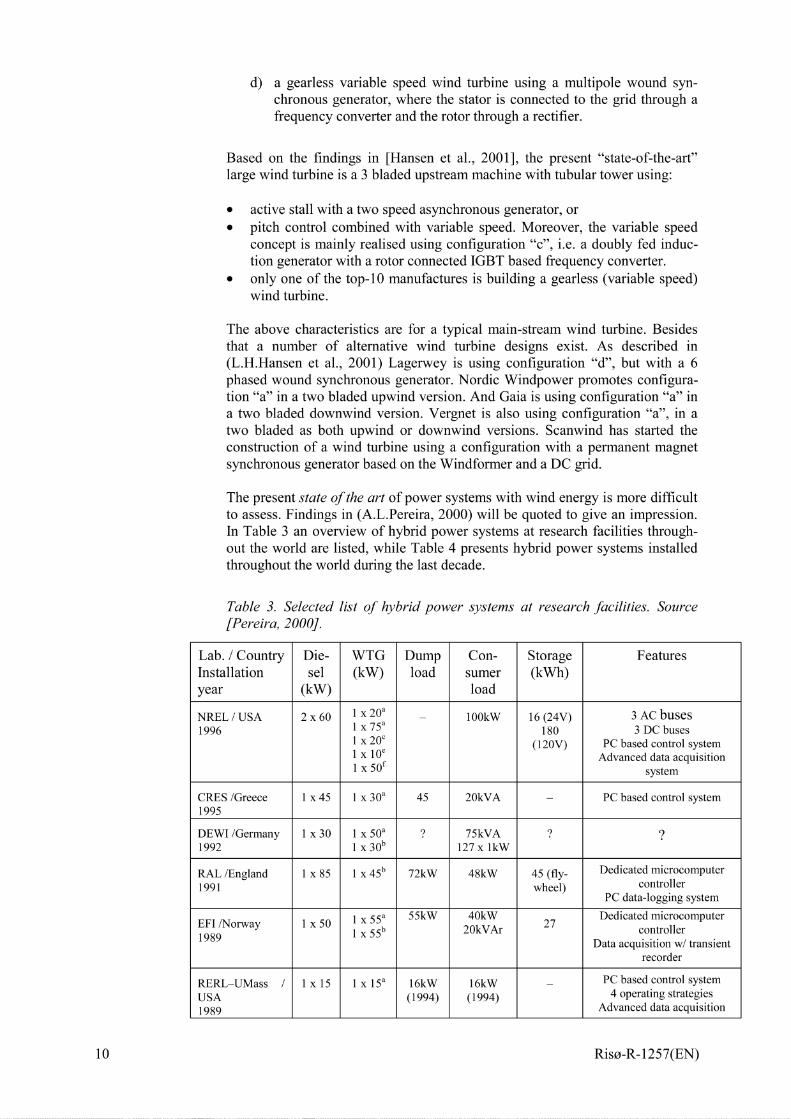
The present state of the art of power systems with wind energy is more difficultto assess. Findings in (A. L. Pereira, 2000) will be quoted to give an impression.In Table 3 an overview of hybrid power systems at research facilities through-out the world are listed, while Table 4 presents hybrid power systems installedthroughout the world during the last decade.
Table 3. Selected list of hybrid power systems at research facilities. Source[Pereira, 2000].
Lab. / Country Die- WTG Dump Con- Storage FeaturesInstallation sel (kW) load sumer (kWh)year (kW) load
NREL / USA 2x60 1 x 20’ 10OkW 16 (24V) 3 AC buses1996 1 x 75’ – 180 3 DC buses
1 x 20’ (120V) PC based control system1 x 10’ Advanced data acquisition1 x 5of system
CRES /Greece 1X45 1 x 30’ 45 20kVA – PC based control system1995
DEWI /Germany 1X30 1 x 50’ ? 75kVA ? ‘?1992 1 x 3ob 127 X lkW
RAL /England 1x85 1 x 45b 72kW 48kW 45 (fly- Dedicated microcomputer
1991 wheel) controllerPC data-logging system
1 x 55’ 55kW 40kW Dedicated microcomputerEFI /Norway 1X50 27
1 x 55b 20kVAr1989
controllerData acquisition WI transient
recorder
RERL–UMass / 1X15 1 x 15’ 16kW 16kW PC based control system
USA (1994) (1994) - 4 operating strategies
1989 Advanced data acquisition
10 Riso-R-1257(EN)

IREQ /Canada1986
AWTS /Canada1985
IUS@ /Denmark1984
Notes: (a) wind tu
1X35
2x50
1X30
ine sim
1 x 50’
1 x 4ob1 x 35’1 X 65d1 X 80’1 x 5of
1 x 55b
17kW
190kW
75kW
50kW
115
—
—
—
30 (400V)(1997)
system (1994)Rotary converter AC-DC-AC
—
—
PC based control systemSophisticated data acquisition
system
‘T, fixed speed induction gen-tor; (b) fixed speed i iuction generator; (c) VAerator; (d) two speed induction generator; (e) variable speed synchronous generator; (f) downwind fixed speedinduction generator.
Riso-R-1257(EN) 11
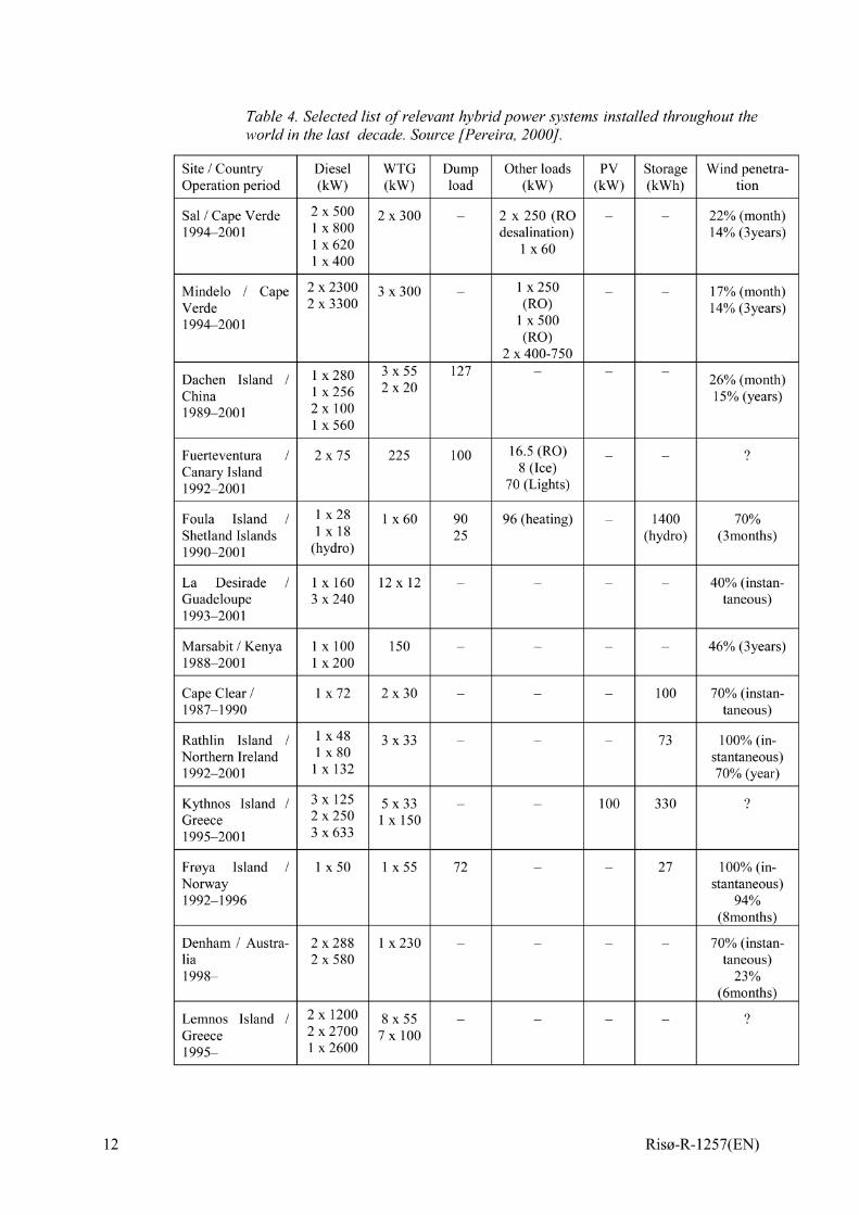
Table 4. Selected list of relevant hybrid power systems installed throughout theworld in the last decade. Source [Pereira, 2000].
Site / Country Diesel WTG Dump Other loads Pv Storage Wind penetra-
Operation period (kw) (kw) load (kw) (kw) (kwh) tion
Sal I Cape Verde 2 x 500 2 x 300 – 2 X 250 (RO – – 22% (month)1994–200 1 ~ X 800 desalination) 14% (3years)
~ X 620 Ix601 x 400
Mindelo / Cape 2 X 2300 3 x 300” – ~ X250 17% (month)Verde 2 x 3300 (RO) - - 14% (3years)1994–200 1 1 x 500
(RO)2 x 400-750
Dachen Island / ~ X280 3x55 127 — — —
2X20 26% (month)China I X256 15% (years)1989–2001 2XIO0
~ X560
Fuerteventura / 2x75 225 100 16.5 (RO) _ _ ?Canary Island 8 (Ice)
1992–200 1 70 (Lights)
Fouls Island / 1x28 Ix60 90 96 (heating) – 1400 70%Shetland Islands 1x18 25 (hydro) (3months)1990–2001 (hydro)
La Desirade / ~ X 160 12x 12 – — — — 40% (instan-Guadeloupe 3 X240 taneous)1993–2001
Marsabit / Kenya 1 x 100 150 – — — — 46% (3years)1988–2001 1 x 200
Cape Clear I 1x72 2x30 – — — 100 70% (instan-1987–1990 taneous)
Rathlin Island / 1x48 3x33 – — — 73 100% (in-Noflhern Ireland Ix80
~ X 132stantaneous)
1992–200 1 70% (year)
K~hnos Island / 3 X 125 5x33 – — 100 330 ?Greece 2 X250 1 x 1501995–2001 3 X633
FrOya Island / IX50 1X55 72 — — 27 100% (in-Norway stantaneous)1992–1996 94%
(8months)
Denham / Austra- 2 X288 ~ X230 – — — — 70% (instan-lia 2 X580 taneous)1998– 23%
(6months)
Lemnos Island / 2 x 1200 8x55 – — — — ?Greece 2 X2700 7x~oo
1995– ~ X2600
12 Riso-R-1257(EN)
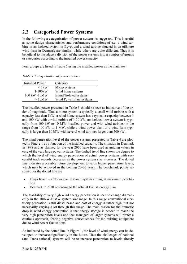
2.2 Categorised Power SystemsIn the following a categorisation of power systems is suggested. This is usefulas some design characteristics and performance conditions of e.g. a wind tur-bine in an isolated system in Egypt and a wind turbine situated in an offshorewind farm in Denmark are similar, while others are quite different. Thus it isbeneficial to introduce a division of the power systems into a number of groupsor categories according to the installed power capacity.
Four groups are listed in Table 5 using the installed power as the main key.
Table 5. Categorisation ofpower systems.
Installed Power Category< lkW Micro systems
1-100kW Wind home systems100kW-10MW Island/Isolated systems
> 10MW Wind Power Plant systems
The installed power presented in Table 5 should be seen as indicative of the or-der of magnitude. Thus a micro system is typically a small wind turbine with acapacity less than 1kW; a wind home system has a typical a capacity between 1and 100 kW with a wind turbine of 1-50 kW; an isolated power system is typi-cally from 100 kW to 10 MW installed power and with wind tirbines in therange from 100 kW to 1 MW, while a wind power plant or a wind farm typi-cally is larger than 10 MW with several wind @rbines larger than 500 kW.
The wind penetration level of the power systems presented in Table 4 are plot-ted in Figure 1 as a fbnction of the installed capacity. The situation in Denmarkin 1998 and as planned for the year 2030 have been used as guiding values incase of the very large power systems. The dashed trend line shows the degree towhich the level of wind energy penetration of actual power systems with suc-cessful track records decreases as the power system size increases. The dottedline indicates a possible future development towards higher penetration levels,which may be achieved in the coming 20-30 years. The benchmark points as-sumed for the dotted line are
● Fraya Island - a Norwegian research system aiming at maximum penetra-tion
● Denmark in 2030 according to the official Danish energy plan
The feasibility of very high wind energy penetration is seen to change dramati-cally in the 10OkW- 10MW system size range. In this range conventional elec-tricity generation is still diesel based and cost of energy is rather high, but notnecessarily varying a lot through this range. The main reason for the dramaticdrop in wind energy penetration is that energy storage is needed to reach thevery high penetration levels and that managers of larger systems will prefer acautious approach, fearing negative consequences for the existing equipmentdue to wind power fluctuations.
As indicated by the dotted line in Figure 1, the level of wind energy can be de-veloped to increase significantly in the future. Thus the challenges of national(and Trans-national) systems will be to increase penetration to levels already
Riso-R-1257(EN) 13
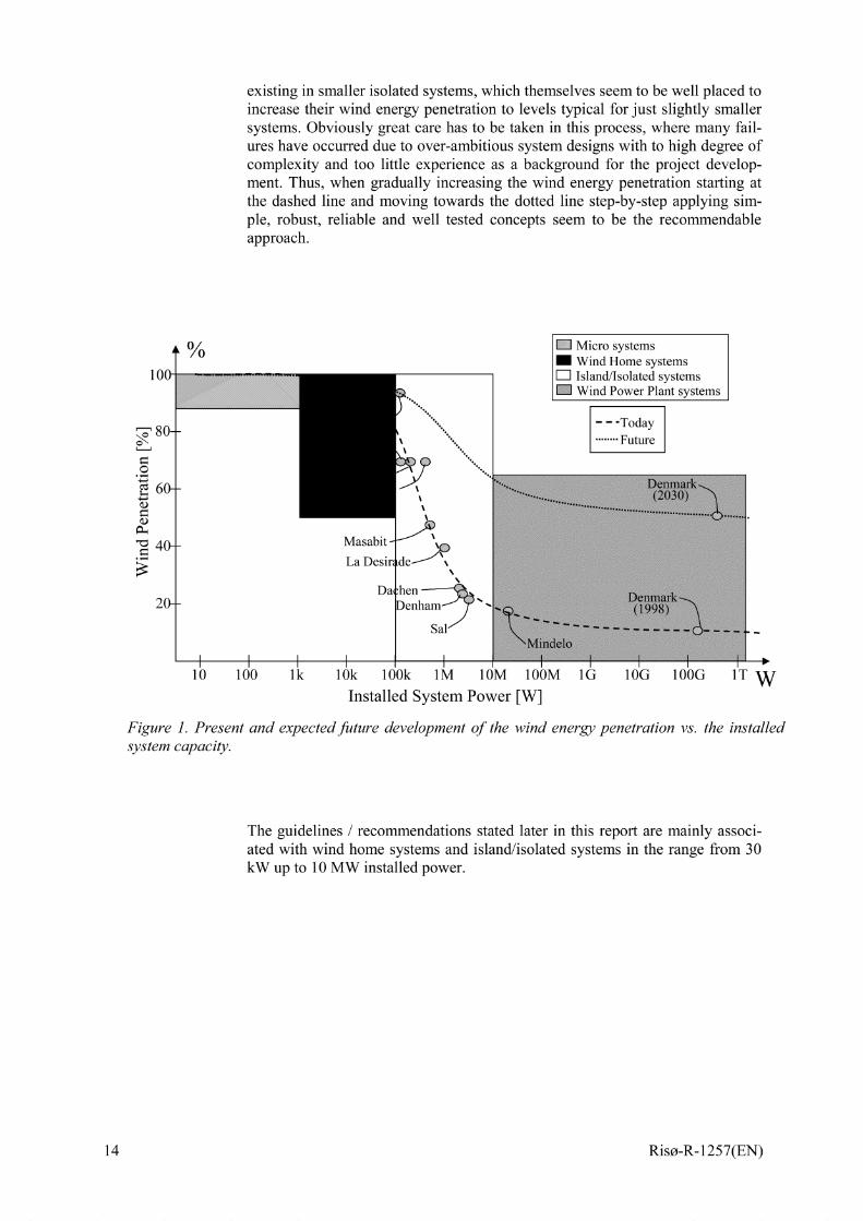
existing in smaller isolated systems, which themselves seem to be well placed toincrease their wind energy penetration to levels typical for just slightly smallersystems. Obviously great care has to be taken in this process, where many fail-ures have occurred due to over-ambitious system designs with to high degree ofcomplexity and too little experience as a background for the project develop-ment. Thus, when gradually increasing the wind energy penetration starting atthe dashed line and moving towards the dotted line step-by-step applying sim-ple, robust, reliable and well tested concepts seem to be the recommendableapproach.
00/
●☛●☛☛
☎☞✌
D Micro systems_ Wind Home systems
1 1 1 1 1
10 100 lk 1ok 1Ools lM 10M 100M 16 1OG 100(3 1’T ~
Installed System l?ower [W]
Figure 1. Present and expected future development of the wind energy penetration vs. the installedsystem capacity.
The guidelines / recommendations stated later in this report are mainly associ-ated with wind home systems and island/isolated systems in the range from 30kW up to 10 MW installed power.
14 Riso-R-1257(EN)
3 State of the Art – Economics
The economics of isolated systems with wind power is not well documented,but a description includes the following issues:
. Cost of electricity in isolated systems
. Cost of electricity from wind tirbines
. Typical electricity production costs of a WD system
Cost of electricity in isolated systems, where existing power supply is typicallyfrom diesel power plants, varies over a very wide range:. Low values of the order 0,20 USD/kWh
. Medium values of the order 0,45 USD/kWh
. High values of the order 1,0 USD/kWh.
Thus the cost of electricity in existing isolated systems is typically many timeshigher than in large utility grids, where production cost of electricity (taxes notconsidered) is of the order 0,04 USD/kWh
Cost of electricity from grid connected wind tirbines has decreased from typi-cally 0,20 USD/kWh in the early 1980’s to now approaching the productioncosts of 0,04 USD/kWh in large grids. The main parameter influencing the COEfrom wind tirbines is the annual average wind speed.
Electricity production costs from WD systems are not well documented, andthey cover a very wide range. Furthermore COE from a WD system maybe dif-ficult to ascertain precisely, as the task maybe outside the scope of small scaleDRE projects. Therefore the economic viability of a WD system will often beassessed by comparing the COE from the wind turbine (including costs of anysupport technology) with the avoided costs due to fuel saving in the existingdiesel system. In case of a retrofit installation of a wind tirbine in an existingWD system this maybe a fair assessment, however, in the planning phase of anew isolated system the comparison should be based on total cost of electricityincluding capital cost of the alternatives analysed.
4 Fact Finding
4.1 Wind Resources & Climate
Knowledge of the characteristics of the climate and especially the wind regimeis crucial for the design and assessment of a potential project with a content ofwind energy. This task should comprise the following:
Riso-R-1257(EN) 15
●
●
●
●
●
●
Identification of existing long-term measurement of wind speed and direc-tion from a meteorological station. Data should preferably be either in time-series format or in histogram for a period of 3-10 years.Assessment of quality of such data
Extrapolation to potential application sites – by WASP or WASP derivedtoolsIdentification of sites for additional wind measurements
Planning and execution of dedicated wind measurements (see (B. H. Bailey& S.L McDonald, 1997)
Obtain maps of the area in digital and paper form. The maps should contain
both height contours and land-use (roughness) contours.
During a site visit, the roughness classification should be obsemed and inter-preted based on the maps and the visual inspection.● at the wind measurement locations and surroundings● at potential wind farm sites and surroundings● at existing long term meteorological stations and surroundings
For a good guide to monitoring of wind and data collection see (B. H. Bailey &S.L McDonald, 1997).
Surroundings of sites and meteorological stations means in this respect up to 10km from the candidate sites for wind turbines and from any meteorological sta-tion, where the influence of roughness is significant for the results of the flowmodelling. Some useful forms for fact finding are included in appendix A.
4.2 End User Needs and Load Demand
The primary objective of the power system is to supply power in order to pro-vide certain services for the community. The single most important task whendesigning a power system is the description of the services that are required.The list of services can be quite long however it is necessary for the assessor toproduce this list as accurately as possible. This has to be done in close collabo-ration with the local community/authority. The list should contain both requiredand desired services for immediate implementation as well as future implemen-tation. Such a list might contain some of the services listed below:
. Domestic: Lighting, TV, refrigerator etc.
. Telecommunication: Repeaters, telephone/fax/internet
. Workshops
● Offices
● Shops. Hotels
. Desalination plants
. Hospitals/Health clinics
● Schools
16
Each of the services should be characterised according to the list below. Energy consumption
. Load profile (day, week)
. Geographical location
. Priority (primary or base, optional, defenable load)
Riso-R-1257(EN)
● Seasonal influenceHaving produced a list of services supplied by the power system including thecharacteristics as above it is possible to aggregate the load for use in the systemanalysis. Since the estimated load is to be used in both the sizing of the compo-nents, determination of the operating strategy and for the technical/economicanalysis the important key figures are the minimum and maximum load and theload profile. It is also important to specify the priority of the load in terms ofprimary, optional and defenable. If there are significant seasonal variationsthese have to be quantified as well.
The final part of the specification of the end user need is to provide forecasts forthe load. Since improvement of the power supply often results in more peopleusing more energy there will typically be a relatively high growth rate in thedemand. The steep increase in the load will of course have a significant impactof the performance of the power system, especially on the ability to supplypower even during peak load periods. The load forecast is also used in the plan-ning of grid extensions including analysis of potential interconnection of theisolated grid either to neighboring grids or to a larger national grid.
The acquisition of consumer load data can be quite difficult especially if theproject is electrification. In existing power systems the only data available willoften be readings by the operator at the power station e.g. hourly and monthlyenergy consumption readings. These data are valuable but are not sufficient fora more thorough analysis of advanced operating strategies. Load forecasts canalso be estimated based on historical data. In case of electrification the load ofthe system has to be entirely based on the assumed loads. In this case the sys-tematic approach outlined above is recommended.
4.3 Existing Power Supply
In order to obtain data on the existing power supply and grid it is recommendedto prepare a questionnaire. The questionnaire should cover generation, distribu-tion and consumption. There are many applications of the data. These includeperformance characteristics (e.g. fuel consumption) for system performanceassessment, condition of the equipment (e.g. gensets and grid) in view of futureuse in the system, extension plans etc. An example of a questionnaire is in-cluded as appendix D. It can be beneficial to divide the questionnaire in order tohave a less detailed one to be used in the initial stage of the analysis and a moredetailed one to be used in the final design. Some of the points to be covered arelisted below.
Number of consumersInstalled capacity, No. generator units, year of commissioning andO&M-statusFor each generating unit specify (base load/ intermediate/ peakloadback-up)System operation: manual/automaticDiesel genset operation: maximum and minimum load, load sharing
cosq at busbargrid-frequency and voltage stability limits and control e.g. type ofgovernor and AVRDistribution: Breakers, protection level, earthing, transformersGrid map: length, cross section, material, overhead lines/cables
Riso-R-1257(EN) 17
18
Operational experience: typical faults, number and duration of outages,maintenance schemesFuel consumptionOperational hours on annual basisTotal consumption (kWh)Diurnal load variationCost of energy, price of energyO&M staff, qualifications etc.Billing proceduresDesign codesPlanning codes (guidelines/ manufacturers framework agreements/ etc.)
4.4 Physical Planning & Infrastructure
The possibilities and limitations imposed by the existing physical planning ofthe community must be taken into account. Examples of issues to be consideredinclude
. Land use and building restrictions
. Development plans for the location in question (land, buildings, industry)
. Permissions needed and ownership issues
● Special protection areas. Environmental restrictions.
The existing infrastructure and its ability to support the level of technology pro-vided by the prospective project must be carefully assessed. Also basic issues ofaccess roads and load carrying abilities should be evaluated, including issuessuch as:●
●
●
●
●
●
●
●
Site access: roads, rails, harbourRelevant wind turbine sites: accessibility, distance to applicable grid
Cost-addition to fuel due to long transport distance
Sustainability of possible wind tirbine equipment: temperature and tem-perature variations, dust, dirt.Access to phone, fax, e-mail.
Accommodation facilities, for temporary construction team and permanentO&M staffShops where common spare parts and tools can be obtainedLocal presence of electronic and mechanical workshops to produce rudi-mentary spare parts on the location and carry out emergency repairs
4.5 Development Trends
The introduction of wind power (and several other renewable energy technolo-gies) implies that considerable investments must be made initially, which meansa long technical/economical project life time (8 – 10 years or more) in order toobtain a reasonably low COE from the system.
Therefore it is necessary to get as much information as possible about the ex-pected development trends for the community in question, in terms of
Riso-R-1257(EN)
. Technical development trends such as expected developments in powerconsumption / end user needs and expected scenarios for the expansion ofpower production facilities by utilities.
. Economic development trends such as expected developments in fuel andlabour cost, capital costs (interest, inflation rates) and taxes/ duties.
. Private projects adding new power plants.
Additional details are offered in Section 6.6.4
5 Project Feasibility Analysis
In the feasibility phase a potential site (or a few sites) are identified for furtherexamination. For the analysis of the technical and economical performance ofthe isolated or WD system a sketch design of the proposed system is carried outand the scenarios to be studied are identified.
5.1 Wind ResourceEstimation of the wind energy resource potential at a given site should be doneusing the Wind Atlas method (see (Riso Wind Energy Dept., 2001)). This im-plies extrapolation of nearby representative wind statistics from a wind meas-urement station taken at a topographically simple site for a climatologicallylong enough period to the potential wind farm site.
The assessment of the wind resource and annual energy production requiressome or all the following:
●
●
●
●
●
●
●
●
Literature, data from WMO, airports and met stations
Existing wind turbine production statistics
Surrounding topography -1:25000 maps, 5-1 Okm distanceAssessment of existing wind data and new measurements at the potentialsitesWASP or a WASP based wind resource assessment tools (see appendix B)Extreme winds and turbulence (from e.g. WASP Engineering (see (J.Mannet al., 2000))
Candidate lay-out of wind turbines (co-ordinates of the tirbines)
Power and thrust coefficient curve(s) of the turbines, hub height and rotor
diameter of the wind tirbines.
5.2 Site Selection. In general: availability of land, human resources and infrastructure
. Adaptation to the national and local development plans and physical sur-roundings
. Physical planning - existing and new requirements for the site and surround-ing land
Riso-R-1257(EN) 19
. Requirements and limitations set by nearby installations - e.g. airports’ obsta-cle limits
. Electromagnetic interference - e.g. airports’ ILS and radio systems, LORANand VOR systems, SOLAS systems, Microwave links, telecom stations,military installations
. Climate in general - temperature, humidity, etc., and its impact on design re-quirements e.g. regarding corrosion protection, cooling, tropicalization, pro-tection against low temperatures etc.
. Soil conditions
. Access to site
. Erection - facilities, conditions, need for landscaping
5.3 Electrical DesignDuring the fact finding the relevant standards and requirements are identified aswell as existing grid codes. These standards, requirements and grid codesshould cover:
● Safety of personnel
. Quality of supply incl. security of supply, quality of voltage and frequency(variations, distortion, flicker etc.)
. Preferred types of equipment
Using this for each of the scenarios the following is assessed:
. Voltage stability
. Frequency (angular) stability
. Steady state behaviour (load flow)
. Assessment of flicker, harmonics etc.
The analysis is carried out with due consideration to the size of the system un-der investigation. For small systems the additional costs involved in performingthe analysis will often be prohibitive. The approach in this case could be somekind of type approval, factory tests and track records (verified references). Forlarge systems the performance requirements will be more demanding and a de-tailed analysis is required.
The electrical design should be as detailed as the technical performance is en-sured and that cost estimates of the complete system can be done. Sketch designof the system is a requirement both in order to be able proper performanceanalysis and system costing but also in order to document various designs con-sidered as part of the study.
The sizing of the components should include the spatial and temporal distribu-tion of the load and generation. This information is collected as part of the factfinding.
●
●
●
●
●
●
●
Electric grid connection – standards& requirements
Drawings and specifications of the grid components
Load distribution in the grid - historical data and forecasts
Sketch design of grid interconnection of wind farmAssessment of potential impact on power quality (applicable standards)
Power system operation and control system communication
Grid reinforcement versus wind power
20 Riso-R-1257(EN)
5.4 Technical PerformanceThe technical performance will be assessed byapplying avariety of measures.These measures include overall system performance as well as performance ofthe individual components ofthe system. For prospective systems thedetermi-nation of the performance figures will usually involve system simulations usinga variety of models each capable of simulating specific aspects of the systembehaviour. This includes screening models, logistic (power flow) models, loadflow models, dynamic models and transient models. In order to be able to cal-culate the specified measures system operating strategies have to be specifiedand implemented in the relevant models. It is also very important to specifyhow the performance is verified on the installed system.
5.4.1 Performance Characteristics
By evaluation of the performance characteristics it is possible to compare thevarious scenarios on system level as well as at a component level. On the sys-tem level the most interesting measures are security of supply, total fuel con-sumption, saved fuel as well as potential and utilised wind energy.
A range of relevant performance characteristics are listed below:
● Conventional generation. Power production
. Running hours
. Fuel consumption
. Fuel tank capacity requirements
. Wind energy. Potential production
. Utilized production
● Capacity factor
● Storage. Energy in/out
. Efficiency
. Life time consumption e.g. charge cycles
. Power Quality& Grid stability
. Loss of load expectatiotiprobability
. Loss of energy
● Voltage quality. Frequency quality
. Supply reliability. Production statistics
. Primary load
. Optional load
. Defemable load
. Penetration of wind energy
. Dumped energy
As is obsemed from the list above the range of performance characteristics isvery wide. Some are calculated on a time scale of years and others are calcu-
Riso-R-1257(EN) 21
lated at a time scale of sub seconds. In the design and analysis phase of a projectthese numbers are calculated using simulation models. Due to the very differenttime scales involved as well as of the different nature of the measures separatemodels have to be applied. A selection of models are listed in section 5.6.
The use of the performance characteristics is twofold. First of all, they are useddirectly in the comparison between the scenarios studied. This includes charac-teristics such as loss of load probability, voltage quality and frequency quality.Secondly, some of the figures are used in the economic performance calcula-tions. These are fuel consumption, utilized wind energy and expected batte~lifetime.
5.4.2 System Configuration and Operating Strategy
The system configuration and operating strategy both play an important role inthe performance of the system. The objectives of the system can be many andinclude high quality power supply for communication purposes, maximum fbelsaving for environmental purposes and lowest operating cost for economic rea-sons. The operating strategy also has a significant impact on the conditions ofthe individual components of the system such as minimum load of the diesels,charge and discharge regime of batteries and voltage variations for the load.
Many considerations have to be taken into account when designing the operat-ing strategy. This include the desired level of automatic operation, the maturityof the system design, the infrastructure of the community served as well as moretechnical matters such as operating conditions of components and the systemobjective.
5.4.3 Technical Performance Verification
A major and very difficult task is to specify procedures for the verification ofthe performance of the system. The main difficulty arises from the fact that thesystem performance specifications are often based on a complex set of assump-tions. These assumptions have to be made in the design phase due to a lack ofdata on the conditions in which the system will be operating.
One approach is to establish the actual operating conditions as accurately aspossible together with measurements of the main system performance measures.The exercise is then to transform the obsemed system performance at the actualconditions to the conditions specified. This can be done using the same modelsas applied in the design phase of the project. It is a difficult task and the resultswill often be open for interpretation. It is recommended to simplify as much aspossible the guaranteed performance data and state the proposed procedure forperformance verification at an early state in order to maintain a high level ofconfidence with the project stake holders.
5.5 Economic PerformanceIt is necessary to distinguish between economic and financial performance.
22
The analysis of economic performance excludes items such as local taxes and isused to provide the community’s decision makers with a basis for comparing
Riso-R-1257(EN)
the investment in the proposed project with other options, not necessarily re-lated to energy production.
Financial analysis results, where local taxes etc. are included, areused to pro-vide the prospective operator/developer and his financiers with a basis for a de-cision on whether the financial returns are satisfactory and thus warrants an in-vestment in the project.
Both types of analysis should be based on life cycle cost analyses as describedin the IEA recommended practice for estimating COE from wind tirbines - see(J.O.G Tande & R.Hunter, 1994).
In a total cost analysis the total power supply system with all installations in-cluding wind power is considered. In this case it is possible to estimate overallCOE for the entire power production.
In an avoided cost analysis the marginal costs and benefits associated withadding wind power to the existing power supply are considered. In this case thecosts of adding the wind tirbine is compared to the benefits of replacing part ofthe fuel consumption of the existing power supply system.
Both technical and economic developments in time should be considered, and ifthe technical lifetime of the installed technology exceeds the economical life ofthe project, the salvage value of the equipment at the end of the economic lifeshould be added to the income of the system.
5.5.1 Project costs
All ordinary project costs should be included in the cost analysis to be carriedover to the track record for COE of the technology. Ordinary project costs in-clude capital costs, O&M costs etc. as outlined below.
Extraordinary project costs for the demonstration aspects of the project shouldnot be included in the cost analysis. Otherwise the track record of the technol-ogy might be confbsed by the seed money necessary to open the market.
Investment costs
If more accurate data are not available from previous or similar projects oneshould use generic data based on established practice.
Wind turbines:
. Std cost/MW installed, additional cost for arctic or other modifications
. Infrastructure: Standard add-on (30Yo) unless specified
Diesel generators:
. Std cost/MW installed, additional cost for arctic, tropical, high altitude etc.
. Infrastructure: Standard add-on (30Yo) unless specified
Auxiliary equipment :. Dump load
. Devices for optional/defenable production (pump, heat, cool, freeze, other)
. Devices for energy storage (batteries, flywheel, pumped storage, other)
. Transpotiation of equipment
Riso-R-1257(EN) 23
. Erection of equipment
. Training
Running costs
The two major operating costs for the diesel generators are
. Fuel cost. A typical specific fuel oil consumption for small diesel generat-ing sets at high loads is 200-250 g/kWh produced (at LHV of 42,7 MJ/kg).For a WD system the diesel generator is often running at low load (<50%)and it is more relevant to consider the fuel consumption as a flow rate (l/h),which is nearly constant at low load. When estimating the fbel cost careshould be taken to use the cost delivered at the site and including all appli-cable taxes.
. Cost of lubricating oil. A typical consumption of lubrication oil is 1-3g/kWh.
O&M costs
Operating and maintenance costs comprise manpower for operation and main-tenance as well as spare parts. Use typical data from similar projects or manu-facturers or use generic data based on established practice.
. Wind tirbines: Percentage of wind turbine investment per year or cost perkWh produced
. Diesel generators: Percentage / fixed cost per operational hour or cost perkWh produced
. Auxiliary equipment by type (e.g. life time/ replacement for batteries)
Retrofit & salvage costs
In general it is recommended to use data from previous or similar projects oth-erwise one should use generic data based on established practices for. Wind turbines
. Diesel generators
. Auxiliary equipment (determination of lifetime and replacement frequencyfor batte~ storage)
. Other costs
Extraordinary project costs
The extraordinary costs are project costs that are to be covered for a pilot /demo system but should not enter the track record because they are not part ofthe regular expenses. Extraordinary costs include:. Engineering support
● Consultancy & supervision● Planning support
● Project& system monitoring
. Evaluation& reporting
24 Riso-R-1257(EN)
5.5.2 Cost of Energy, COE
The COE should be calculated based on a life cycle cost analysis along thelines of the IEA Recommended Practice for COE from grid connected windturbines ((J.O.G Tande & R. Hunter, 1994)). Items include. Financial vs. economic COE
. Discount rate(s)
● Capital costs
● O&M Costs. Retrofit Costs
● Salvage value. Levellised COE
5.5.3 Value of Energy, VOE
The VOE is input to a Life Cycle Cost analysis of return on the investment inthe project and the operation of the system. Items include. Baseline scenario for existing power supply
. Cost& price structures, subsidies
. Tariffs, PPA for sales of electricity
. Fuel costs, total& avoided by adding the equipment of the project
. Externalities i.e. incremental costs related to e.g. greenhouse gas abatement
Primary power supply
Primary power supply denotes consumer loads that must (in principle) alwaysbe met upon demand. It is characterised by
● VOE according to existing tariffs/ PPA. Industry and household electricity demands
. Street lights and other public demands
. Base loads for e.g. water pumping, desalination, heating, cooling etc.
Optional loads
Optional power supply denotes consumer loads that can be met if and whenpower is available after the primary load demand is met. It is characterised by. Utilisation of dump load power for e.g. water pumping, desalination, heat-
ing, cooling etc.
. VOE is typically lower than primary power and should be estimated if notincluded in the tariffs or PPA
Deferrable loads
Defemable power supply denotes consumer loads that must be met within acertain span of time but maybe met if& when power is available after primaryload demand is met. It is characterised by
. Utilisation of dump load power for e.g. water pumping, desalination, heat-ing, cooling etc.
. VOE is typically lower than primary power and should be estimated if notincluded in tariffs or PPA
. If defenable loads are not met within a certain time span they become pri-mary loads
Riso-R-1257(EN) 25
Externalities
Externalities are the term often used for the values that are associated with re-newable energy production but not accounted for in the traditional economicanalysis. They include
. Reductions in greenhouse gas emissions. Values are assigned on a na-tionaVregional/global level.
. Reduction of harmful air borne emissions e.g. NOX, S02 and particulateemissions. Values are assigned on a regional/local level.
. Reductions in fuel and oil spillage. Values are assigned on a local level
. Reductions in noise levels and other disturbances. Values are assigned on alocal level
Externalities can only be included in the assessment of operational economy ifthey are actually paid for by customers. Externalities maybe used to obtain partof the investments on favorable conditions, e.g. from GEF on a global level orby governments on a national level, and in such cases externalities can be in-cluded in the assessment of the operational economy of the project.
5*5*4 Development Scenarios
The technical-economical project life associated with implementing wind en-ergy into an isolated power supply system will be many years, frequently up to20 years. Therefore, the scenario to be analysed should include a developmentscenario that represents the assumed development in both technical and eco-nomical/financial terms.
Technical development includes the development of parameters such as
. Consumer demand in terms of primary and secondary load types
. Generating capacity in terms of e.g. active diesels and their replacements /extensions
. O&M needs as generating capacity ages and expands
. Operating strategy and priorities
Economical development includes the development of parameters such as
. Consumer rates and tariffs
. Fuel costs and prices
. O&M costs as existing generating capacity ages and new capacity is added
. Major repairs/ overhaul/ retrofit
Financial development includes the development of parameters such as. Inflation
. Interest rates
. Taxes, duties and deductions
26
Ideally the development scenario should be represented by tables speci~ing theassumed values of the above parameters year by year during the entire projectlife. The technical-economical models used should be able to utilise this infor-mation in a life cycle cost analysis.
Riso-R-1257(EN)
5.5.5 Assessment of Results
The results of the economic/financial analyses come in the form of annual cashflows specifying the projected expenses and income from the installation andoperation of the project. The economic/financial indicators used to assess theresults include. Levelised production cost, LPC (cost/kWh) of wind energy,
. Sort run marginal cost, SRMC (cost/kWh) - with and without the assessedwind power plant.
. Net present value, NPV of the project
. Economic internal rate of return, EIRR (Yo p.s.) of the project
. Financial internal rate of return FIRR (Yo p.s.) of the project
. Return on Equity ROE (Yo p.s.) for the investor
. Simple payback time (years) of the project
. Cost of alternative technologies (relevant for the case considered) e.g. solar,hydro etc.
The results will be assessed by comparing the economic/financial indicatorswith the criteria / threshold values applied by the investor/financier/donor inquestion for the project.
5.6 Modelling & SimulationThe technical and economical performance of prospective systems is analysedby computer simulation of the systems, and several types of models are useddepending on the characteristics on which the simulation is focused. The mainparameter characterizing the models is the time scale of the simulation, and weusually distinguish between the following types:
. Screening models give an overall assessment of the performance of thesystem, without going into very much detail of the specifics in the operationof the system.
. Logistic models focus on predicting the annual power productions, fbelsavings and power flows in the system. Logistic models are usually the ba-sis in screening models, and they may be deterministic time series modelsor probabilistic models that produce probability distributions.
. Dispatch models focus on the dispatch of the various power producingcomponents of the system, i.e. start/stop of diesels etc. Time scale typicallyminutes to an hour.
. Dynamic models focus on the electromechanical behaviour of the system,i.e. machine dynamics but not electrical switching may be represented.Time scale typical a few seconds to half an hour.
. Transient models focus on electrical transients including switching. Timescale typically seconds to minutes.
System control models focus on a representation of control strategies of thesystem, or parts of the system. Dispatch type models are usually the basis forsystem control models.
A number of numerical modelling techniques and models are available for theassessment of technical-economic performance the system. Riso R- 1109 pres-ents a review of models, and selected models from the review are briefly de-scribed below:
Riso-R-1257(EN) 27
HOMER is a fast & comprehensive village power systems screening model,now (1998) supplemented with the VIPOR model for optimal layout of a supplyarea into grid connected vs. independently supplied consumers. State of the artin this category, but not publicly available. (P. Lilienthal et al., 1995)
INSEL Offers almost unlimited flexibility in specifying system configurationsby allowing the user to specify the connectivity on a component level. Intendedas an out-of-house-model. (Renewable Energy Group, 1993)
HYBRID2 The state-of-the-art (1998) time series model for prediction of tech-nical-economical performance of hybrid wind/PV systems. Offers a very highflexibility in specifying the connectivity of systems. Publicly available and quitewidely used. (H. J.Green & J.Manwell, 1995)
SIMENERG The only model so far with a very high degree of flexibility in thecontrol / dispatch strategy, using a “market square” approach, where the eco-nomically optimal subset of power sources that satisfy the power demand isdispatched in each time step. (C.Briozzo et al., 1996)
WINSYS is a spreadsheet (QPW) based model implementing probabilistic rep-resentations of resources and demands. WINSYS incorporates the anticipatedtechnical expansions during its lifetime in the technical performance measures,combined with a traditional economic life cycle cost assessment. ThusWINSYS represents a more real life cycle cost analysis than most other models.It is not commercially available. (J. C.Hansen & J.O. G. Tande, 1994)
ENGINEERING DESIGN TOOLS FOR WIND DIESEL SYSTEMS, Thispackage contains seven European logistic models: SOMES (NL), VINDEC (N),WDILOG (DK), RALMOD (UK) and TKKMOD (FIN). It also includes themodular electromechanical model JODYMOD. (D. Infield, 1994)
PROLOAD A probabilistic load flow analysis code, using Monte Carlo tech-niques, developed in co-operation with an electrical utility for dimensioning ofdistribution systems with wind tirbines. (J. O. G. Tande et.al., 1999)
RETScreen is a spreadsheet (Microsoft Excel) based analysis and evaluationtool for assessment of the cost-effectiveness of potential projects with renew-able energy technologies. The software package consists of a series of work-sheets with a standardised layout as well as an online manual and a weather andcost database. The tool is developed by the CANMET Energy DiversificationResearch Laborato~ (CEDRL) and is available from the Website of CEDRL.(CEDRL, 2000)
5.7 Uncertainties and Sensitivity AnalysisAs the modelling techniques used imply (often considerable) uncertainties theresults should not be taken as an accurate representation of the reality of thefuture. They should rather be taken as one possible manifestation, and theyshould be supplemented by an analysis of the impact of the major uncertainties.The most important types of uncertainties are
28
. Modelling uncertainties
. Input data uncertainties
● Parameter uncertaintiesThe sensitivity to changes in assumptions and input data is usually ascertainedby running the models a number of times, where each time one parameter ischanged while the other are kept constant. This way the sensitivity of results tovariations in the assumptions is estimated, and this is a very important aspect of
Riso-R-1257(EN)
the analyses. The results of a sensitivity analysis is usually presented in so-called spider diagrams
5.8 Environmental ScopingAt the same time as carrying out technical and economical analyses, developersshould also consider the environmental acceptability of potential sites. The ini-tial environmental acceptability considerations (commonly known as environ-mental scooping) will mainly be based on studies of existing data. A review ofreports, equipment performance specifications and maps of the area should becarried out in order to determine specific technical or environmental issues, de-velopers should be aware of considering existing and emerging national, re-gional and local planning policies.
The following issues should be addressed at a preliminary level, each of whichwill be studied in greater detail in subsequent phases of the project develop-ment:
●
●
●
●
●
●
●
●
●
Visual ImpactProximity to dwellings (existing and planned)
Ambient air quality
Noise
Sensitive Ecology /rare or endangered speciesArchaeological / historical heritage
Areas for Recreational use /national parks / reserves
Interference with telecommunications
Planning issues e.g. civil and military airports
Scoping document
The scooping phase will briefly review the data already available and identi~the environmental issues that will have to be subsequently reviewed in detail.The results are normally summarised in a scooping document or report.
Riso-R-1257(EN) 29
6 Environmental Impact Analysis
In projects, where it is likely that the proposed project will have significant ef-fects on the environment by virtue of factors such as its nature, size or location,it may require a more detailed environmental impact analysis.
A full and comprehensive environmental impact assessment consist of an analy-sis of the following:
●
●
●
●
●
●
●
●
●
Policy and legislation framework
Plant design documented in a project description with emphasis on envi-ronmental impactAnalysis of present or baseline situation (emphasize what is particularlysensitive)Environmental impact assessment (Construction phase)
Environmental impact assessment (Operation phase)
Analysis of alternatives
Describe mitigation measures to decrease the environmental impact
Outline of monitoring in the construction and operation phase.Public Consultations
The list of contents above is generally accepted as the basis of a full environ-mental assessment of a project and is widely used internationally among othersby the World Bank and other financial institutions as well as consultants. Forreference see the World Bank /IFC Operational Procedure for environmentalassessment included in appendix C. In case of large projects it is recommendedto follow the full environmental review procedure outlined above, while forsmall projects and /or projects with a limited impact on the existing environ-ment a reduced scope can be applied. In many such cases the environmentalscoping report will be sufficient to satisfy the needs of the stakeholders of theproject including the local authorities and the financing body.
The following topics are considered in the environmental analysis:
●
●
●
●
●
●
●
●
●
●
●
●
●
Site selectionAmbient air quality
Visual and landscape assessment
Noise assessmentAssessment of flora and fauna
Archaeological and historical heritage
Hydrological assessment
Interference with telecommunication systems
Aircraft safety
Safety assessmentTraffic management and construction of access roads
Landscaping and deposit of waste during the construction
Socio-economic effects
30 Riso-R-1257(EN)
In particular for the main components of the WD plant:
6.1 Diesel Generating Set. Exhaust Gas Emissions: NOX SOZ and particulate matter
. Global warning effects from COZ
. Noise emission
. Risk of fbel spills
. Disposal of used lubrication oil
6.2 Wind Turbines● Visual impact
. Noise emission
. Shadows and blinks
. Impact on flora and fauna - e.g. danger for rare species, migrating birds
. Impact on reservation areas, archaeological sites or other special interests
. Probability and consequences of accidents to humans or nature
6.3 Desalination. Impact of raw water supply on level of aquifer or marine life
. Disposal of cone. and warm brine
● Use of additives to control of scale formation and biocides to prevent or-ganic growth
. Impact on drinking water quality and health aspects
6.4 Battery Storage. Risk of leaks
. Expected lifetime and disposal after use
6.5 Socio-economic and Sociological Issues
Socio-economic and sociological issues are often neglected in the evaluation ofviability of a project. This is due to the fact that the items related to the socio-economic and sociological issues can be difficult to assess and moreover it canbe quite difficult to prescribe/estimate a fair price/cost of these items. An im-portant example is environmental externalities.
Nevertheless, evaluation of socio-economic and sociological issues should bequantified and analysed as much as possible. The keywords are identificationand quantification of relevant issues. In general terms the methodology there-fore comprises two tasks:
1) identify and assess the benefits of rural electrification.2) quantify the costs of rural electrification.
Riso-R-1257(EN) 31
Examples of socio-economic and sociological issues to be considered are listedbelow. What is the impact:
● on economic growth.● on agricultural production and rural industrialisation,● on the unemployment rate● on the quality of rural life.● on incomes and poverty alleviation.● on migration and birth rates.● on the environment.
Based on these findings a comparison of benefits and costs can be performed –preferably both on a monetary and a non-monetary manner. The monetary partshould of course be added to the economic analysis as project costs. See e.g.(F.Fluitman, 1983) and (World Bank Group, 1998)
7 Institutional and Legal Framework
The importance of institutional issues is illustrated by the fact that it has fre-quently been demonstrated that technically feasible but institutionally problem-atic projects will not work. These issues should be paid a proper attention byproject developers. Institutional issues denote a range of non-technical issuesthat are outlined in this section.
7.1 Legal Issues
It is necessary to clarify which (if any) legal framework exists for the utilisationof wind energy in the prospective case of isolated power supply. Issues include:. Policies & incentives for wind energy
. Rights & conditions to build/erect/install wind energy equipment
. Rights & conditions to connect to busbar / grid / substation
. How and by whom are the policies, incentives, rights and conditions deter-mined?
. Which standards& regulations apply?
7.2 Ownership and ResponsibilitiesThe ownership of the project and subsequent the plant should be clearly de-fined. Is the owner a
● Utility. IPP organised as Ltd.
● Co-operative. BOO/ BOOT scheme
32
On the rights and obligations of the ownership:. Rights to connect to the grid and produce power
. Agreements on how to get revenues (PPA)
. Obligation or right to produce/repair/remove/replace/expand
Riso-R-1257(EN)
In a project with multiple partners a clear definition of the responsibilities in thedevelopment, construction and operation phase of the project is vital for a goodprogress of the project.
7.3 StakeholdersThe parties with an interest in the project should be identified as well as the na-ture of their interest
. Community council/ local authorities
. Regional/ governmental authorities
. Power supply responsible/ companies/ utilities
. Consumers/ consumer groups/ consumers with special needs
. Experts/ expert groups/ associations/ knowledge centres
. Industry/ manufacturers (local vs. regional/ national)
. Neighbors
Outline the structure of interests and try to identi~ possible conflicts of interestthat could jeopardise or delay the project
7.4 Technology CarriersIdentification of parties with a capability to participate in the necessary technol-ogy transfer and to make the technology available to the community in question(region / nation). It should be considered how to involve such parties in theproject. Potential parties are
● Power supply entities
. Private industry
● Service organisations
. Government agencies
● Universities
7.5 Sustainability / replicationThe sustainability and replication potential of the project should be assessedbased on institutional issues as well as findings from technical, economical, andmarket & policy issues.
8 Financing
Before the project sponsor or developer approach a potential investor or afunding agency e.g. a bank or an aid organisation it is recommended to considerthe following:
. Prepare a project outline description
. Proposed time schedule for implementation
. Project investment including breakdown in major items
. Relevant economical and financial key figures or indicators for the project
Riso-R-1257(EN) 33
. Adraft PPAorother evidence ofpotential income
. Costofland (inapplicable) andaccess right/roads
. Environmental scoping report/ statement
The sources of project financing are●
●
●
●
●
●
9
Traditional private national sources
Traditional private international sources
World Bank / IFC, GEF, PCF
Other multilateral organisations: Inter-American Development Bank, AsianDevelopment Bank, African Development Bank etc.
National aid organisations e.g. DANIDAPrivate non-governmental organisations
Implementation
An important issue is to select a suitable scheme for implementation of the proj-ect. An essential issue is to maintain a clear definition of the responsibilitythroughout the design, transportation of components, erection and commis-sioning of the plant. Subsequently in the operation phase it should be clarifiedwhich party has the capability to operate, maintain and monitor the plant.Monitoring and reporting including development and assessment of operationpatterns is of utmost importance for the fbrther development of isolated powersystems.
. Implementation Schemes (turnkey, BOOT, etc.)
. Engineering design of WD Plant
. Identification of local specialists
. Assessment of the need for Ex-pats
. Logistics of spare parts, fuel and lubrication oil
. Establishment of an O&M organisation
. Monitoring and reporting
10 Conclusion and Recommenda-tions
A number of issues have been identified which should be considered when de-veloping a wind power project in an isolated power system. The main charac-teristics of a successful project maybe summarised as follows:
. The use of updated versions of relevant international standards – includingthe one for decentralised power systems with renewable energies now inprogress within the IEC.
34
. That best practice guidelines for project implementation are applied includ-ing common references and relevant experience from recent projects.
Riso-R-1257(EN)
●
●
●
●
●
●
●
●
That the wind power project in the isolated system in question is part of aconcerted action in a national and international programme rather than an in-dividual project.
That the wind power technology applied in a small to medium size systemfollow simple and proven approaches, e.g. by repeating and/or downscalingpilot and demonstration systems with positive track records, which may havebeen developed from filtering down from large-scale systems any techno-logical achievements adaptable to smaller systems.
That small systems are developed and specified to apply rugged technologysuitable for remote communities.
That no experimental systems are installed at rural remote communities un-less previously thoroughly tested and documented at test benches dedicatedto serve as experimental facilities
That ownership is well defined with a built-in interest identified to ensurelong-term interest and funding of operation, maintenance and re-investmentswhen needed.
That an organisation is established with the necessary capacity and capabili-ty for implementation, operation and maintenance, preferably including theback-up from a relevant national or regional knowledge centre.
That a sufficiently detailed feasibility study has been performed.
That modelling assumptions, input data and methodology applied for thefeasibility study and system design reflect the true hardware reality for thetypes of systems in question
The technical capacity to design, build and operate isolated power systems witha high penetration of wind power exists, but the mature product and the markethave not yet met. Nevertheless, there is today an industry offering small windturbines (10 - 300kW) for hybrid system applications with a long-term com-mitment in this business. This indicates their belief that a market is emerging sothat interest also from some of the large wind tirbine manufacturers can be ex-pected.
The above recommendations are seen as moves that would all lead in the direc-tion of a development of the use of wind power in isolated power systems. Thiswill open up and extend access to electricity for the benefit of the developmentof small rural communities.
Riso-R-1257(EN) 35
References
A. L.Pereira. (2000).Systems.
Modular Supervisory Controller for Hybrid Power
B. H. Bailey, & S.L McDonald,A.S. (1997). Wind Resource AssessmentHandbook. NREL Golden CO.
C.Briozzo, G. Casaravilla, R. Chaer, & J.P. Oliver. (1996). SIMENERG: TheDesign of Autonomous Systems pp. 2070-2073. In WREC.
RETSCREEN Pre-feasibility Analysis Software: www.retscreen.gc.ca[Computer Software]. (2000). CANMET Energy Diversification Re-search Laborato~ (CEDRL).CEDRL.
D. Infield. (1994). Engineering Design Tools for Wind Diesel Systems. En-ergy Research Unit, Rutherford Appleton Laborato~.
EDF. (1997). Specifications for the Use of Renewable Energies h RuralDecentralised Electrification. Electricity De France. IEC/PAS 62111ver 1.0.
F.Fluitman. (1983). The Socio-Economic Impact of Rural Electrification onDeveloping Countries: A Review of Experience. In World EmploymentProgramme Reaseach Working Paper: Vol. WEP 2022/wp126. ILO.
H. J.Green,& J.Manwell. (1995). HYBRID2 - A Versatile Model of the Per-formance of Hybrid Power Systems pp. 437-446. In Vol. Wind-power’95 Proceedings of AWEA.
J.C. Hansen,& J. O. G. Tande. (1994). High Wind Energy Penetration SystemsPlanning. In EUWEC’94 Thessaloniki, Greece.
J.Mann, P Astrup, L.Kristensen, O. Rathmann, P.H. Madsen, & D. Heathfield.(2000). WASP Engineering DK. Riso National Laborato~: R-1 179(EN).
J.O.G Tande, & R. Hunter. (1994). IEA Recommended Practices for WindTurbine Testing and Evaluation: 2. Estimation of Cost of Energy fromWind Energ Y Conversion Systems. Risa National Laborato~, Den-mark and NEL, United Kingdom.
J.O. G. Tande et.al. (1999). Power Ouality and Grid Connection of WindTurbines. Part 1: Stationary Voltages.
L. H. Hansen, L.Helle, F.Blaabjerg, E.Richie, S.Munk-Nielsen, H. Bindner,P. Sorensen, & B. Bak-Jensen. (2001). Conceptual Survey of Generatorsand Power Electronics for Wind Turbines. Riso National Laborato~:Riso R-1205 (EN).
36 Riso-R-1257(EN)

P. Lilienthal, L.Flowers, & C.Rossmann. (1995). HOMER: The Hybrid Op-timization Model for Electric Renewable. pp 475-480. In Vol. Wind-power ’95 -Proceedings AWEA.
Renewable Energy Group. (1993). INSEL Reference Manual. (version 4.80cd.). Dept. of Physics, Univ of Oldenburg.
Riso Wind Energy Dept. Wind Atlas Analysis and Application Program(WASP). Internet . 2001. Riso National Laborato~. (GENERIC)Ref Type: Electronic Citation.
World Bank Group. (1998, July). Pollution Prevention and AbatementHandbook: The Effects of Pollution on Health: The Economic Toll.Washington DC.
Riso-R-1257(EN) 37

Appendix A Tables and Forms forFact Finding
38
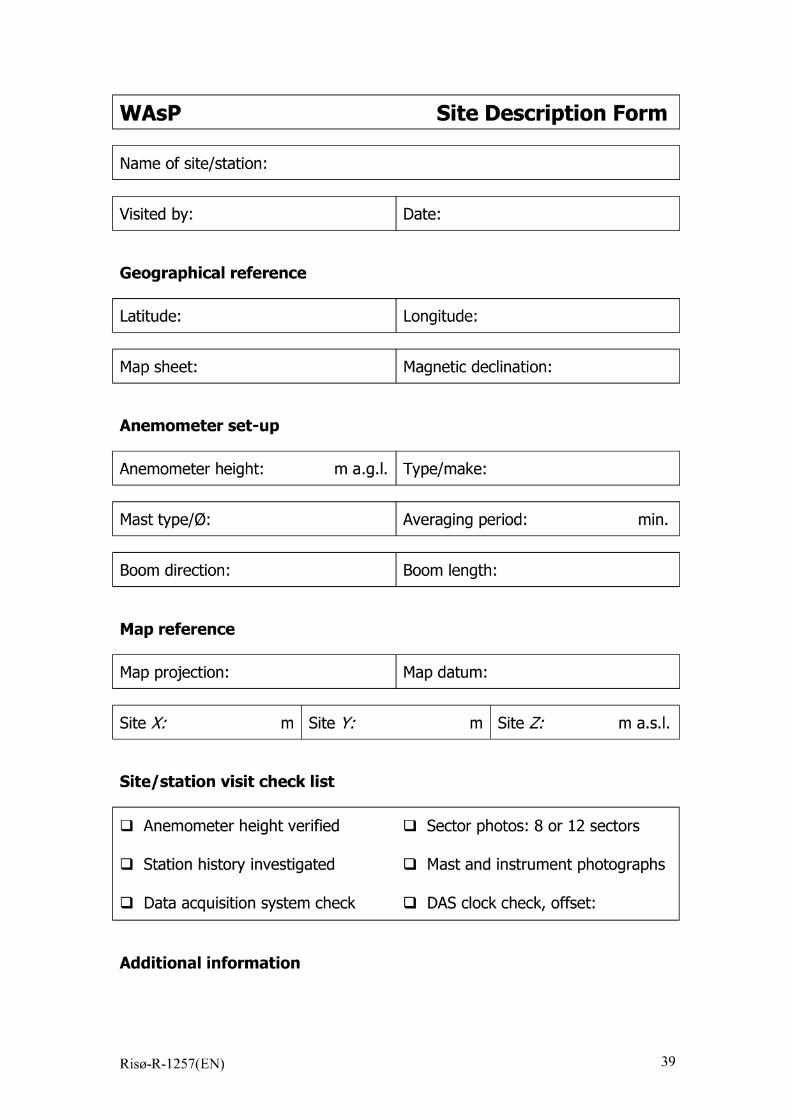
WASP Site Description Form
Name of site/station:
Visited by: Date:
Geographical reference
Latitude: Longitude:
Map sheet: Magnetic declination:
Anemometer set-up
Anemometer height: m amgmlmType/make:
Mast type/@: Averaging period: min.
Boom direction: Boom length:
Map reference
Map projection: Map datum:
Site X: m Site )0 m Site Z; m amsmlm
Site/station visit check list
❑ Anemometer height verified ❑ Sector photos: 8 or 12 sectors
❑ Station history investigated ❑ Mast and instrument photographs
❑ Data acquisition system check ❑ DASclock check, offset:
Additional information
Riso-R-1257(EN) 39
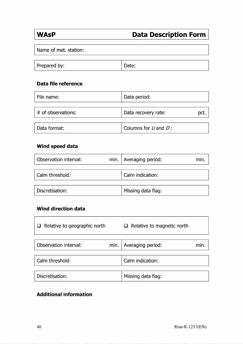
WASP Data Description Form
Name of met. station:
Prepared by: Date:
Data file reference
File name: Data period:
# of obsewations: Data recovery rate: pet ■
Data format: Columns for Uand 1):
Wind speed data
Obsewation intewal: min. Averaging period: min.
Calm threshold: Calm indication:
Discretisation: Missing data flag:
Wind direction data
❑ Relative to geographic north ❑ Relative to magnetic no~h
Obsewation intewal: min. Averaging period: min.
Calm threshold: Calm indication:
Discretisation: Missing data flag:
Additional information
40 Riso-R-1257(EN)

WASP Obstacle Description Form
Name of site:
Visited by: Date:
a1 R 1 a 2 R2 H d P Comments
Note: q and a2 are given in degrees clockwise from notih and RI, R2, hand d in metres.
Riso-R-1257(EN) 41
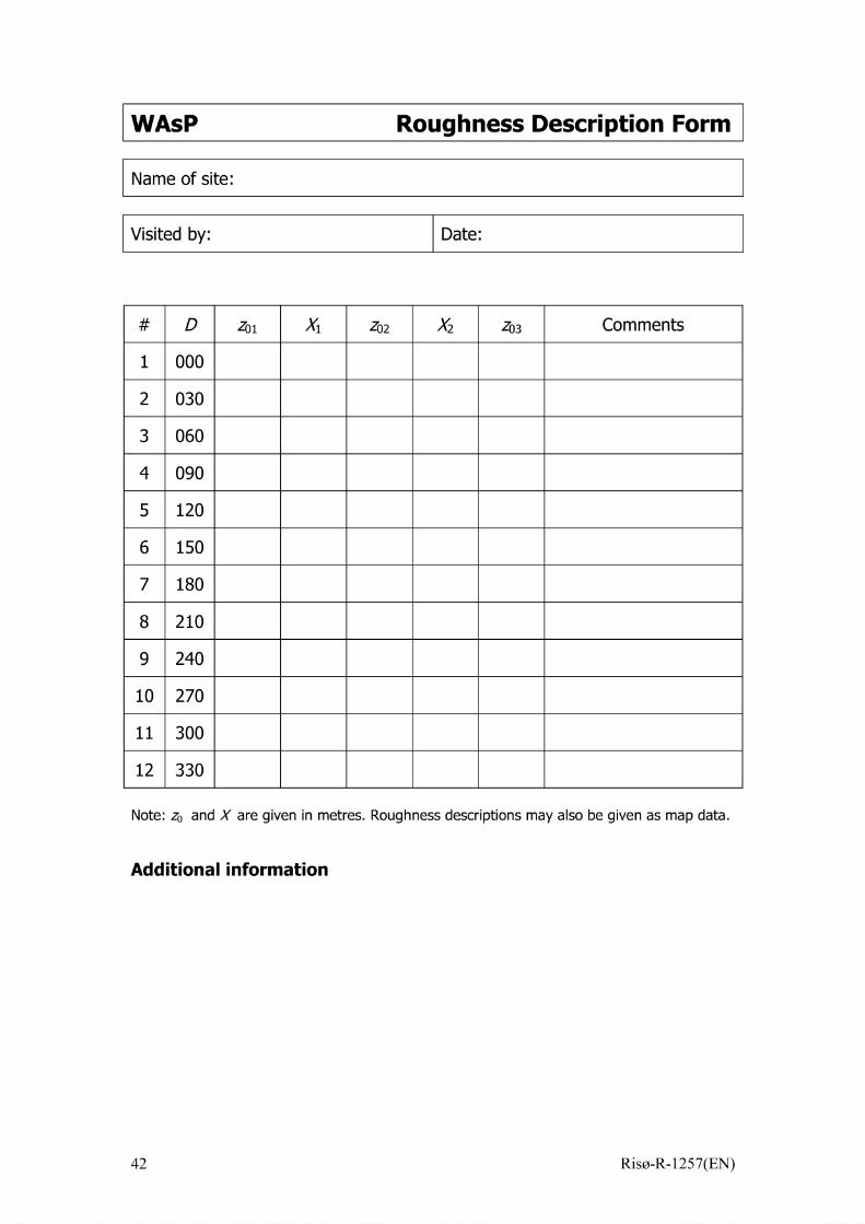
WASP Roughness Description Form
Name of site:
Visited by: Date:
D Zol x 1 Z02 x 2 zo~ Comments
1 000
2 030
3 060
4 090
5 120
6 150
7 180
8 210
9 240
10 270
11 300
12 330
Note: ZO and X are given in metres. Roughness descriptions may also be given as map data.
Additional information

Appendix B
m
m
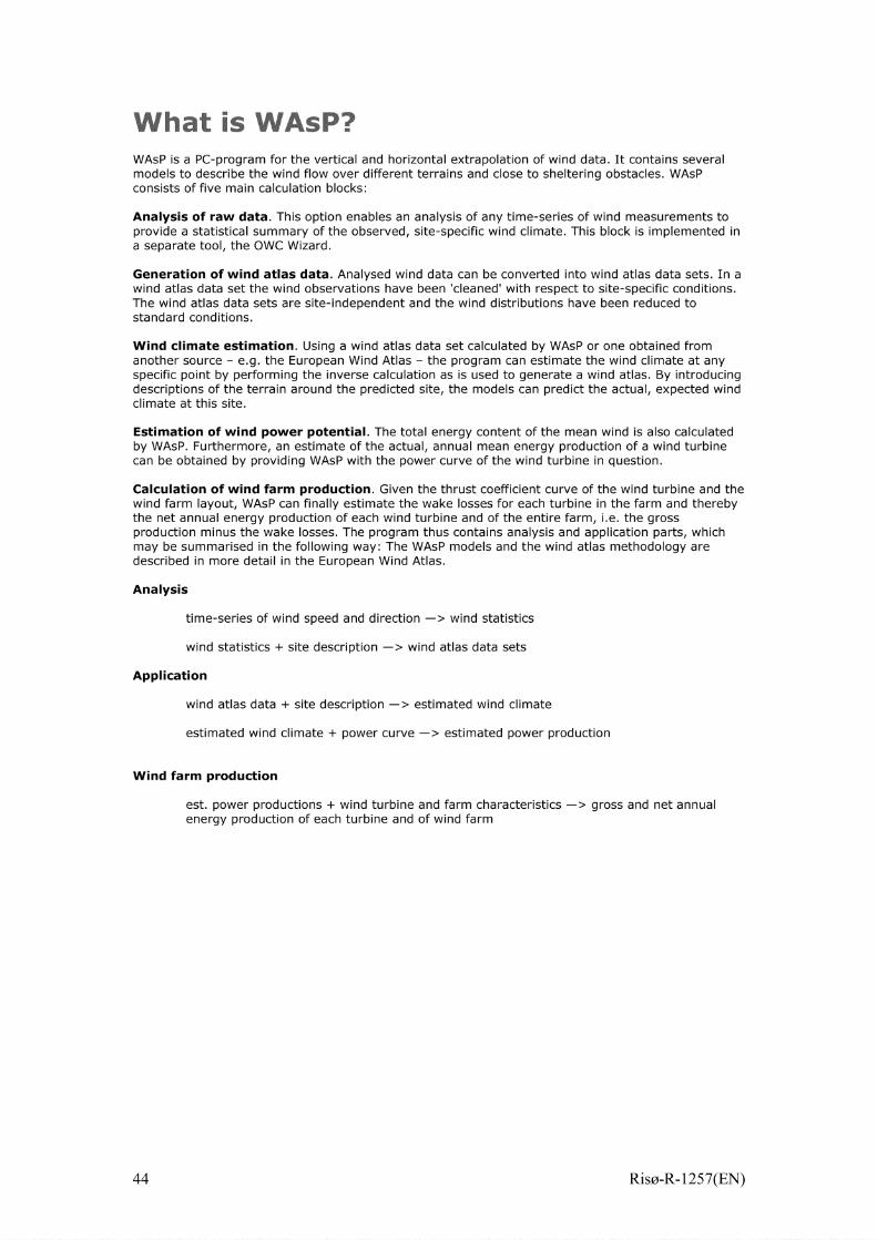
WASP is a PC-program for the vertical and horizontal extrapolation of wind data, It contains severalmodels to describe the wind flow over different terrains and close to sheltering obstacles, WASPconsists of five main calculation blocks:
Analysis of raw data, This option enables an analysis of any time-series of wind measurements toprovide a statistical summary of the observed, site-specific wind climate, This block is implemented ina separate tool, the OWC Wizard,
Generation of wind atlas data, Analysed wind data can be converted into wind atlas data sets, In awind atlas data set the wind observations have been ‘cleaned’ with respect to site-specific conditions,The wind atlas data sets are site-independent and the wind distributions have been reduced tostandard conditions,
Wind climate estimation, Using a wind atlas data set calculated by WASP or one obtained from
another source – e-g, the European Wind Atlas – the program can estimate the wind climate at anyspecific point by performing the inverse calculation as is used to generate a wind atlas, By introducingdescriptions of the terrain around the predicted site, the models can predict the actual, expected windclimate at this site,
Estimation of wind power potential, The total energy content of the mean wind is also calculatedby WASP. Furthermore, an estimate of the actual, annual mean energy production of a wind turbinecan be obtained by providing WASP with the power curve of the wind turbine in question,
Calculation of wind farm production, Given the thrust coefficient curve of the wind turbine and thewind farm layout, WASP can finally estimate the wake losses for each turbine in the farm and therebythe net annual energy production of each wind turbine and of the entire farm, i-e, the grossproduction minus the wake losses, The program thus contains analysis and application parts, whichmay be summarised in the following way: The WASP models and the wind atlas methodology aredescribed in more detail in the European Wind Atlas,
Analysis
time-series of wind speed and direction —> wind statistics
wind statistics + site description —> wind atlas data sets
Application
wind atlas data + site description —> estimated wind climate
estimated wind climate + power curve —> estimated power production
Wind farm production
est, power productions + wind turbine and farm characteristics —> gross and net annualenergy production of each turbine and of wind farm
44 Riso-R-1257(EN)

Appendix C Environmental As-sessment
Riso-R-1257(EN) 45
Arabic Chinese French m Portuguese Russian
Note: OP 4.01 replaces the policy elements of IFC’S EnvironmentalAnalysis and Review of International Finance Corporation Projects(Washington, D.C.: IFC, 1993). IFC’S Procedure for Environmental andSocial Review went into effect as of September 1, 1998. Instructions to staffon public consultation and disclosure are contained in IFC’S Policy onDisclosure of Information (Washington, D. C.: IFC, 1997). Additionalinformation related to this OP is provided in the Environmental AssessmentSourcebook (Washington, D.C.: World Bank, 1991) and subsequentupdates available from the Environment Sector Board and in the PollutionPrevention and Abatement Handbook. Other IFC policies that relate to theenvironment include OP 4.04, /Vatum/ Habitats; OP 4.09, PestManagement; OP 4.10, Indigenous Peoples (forthcoming); OP 4.11,Safeguarding Cultural Propedy in IfC-Financed Projects (forthcoming); OP4.12, Involuntary Resettlement (forthcoming); OP 4.36, Forestry; OP 4.37,Safety of Dams (fodhcoming), and OP 7.50, Projects on InternationalWaterwaysm
Questions may be addressed to the Associate Director, IFC’S Environmentand Social Development Depafiment. Additional copies are available to IFCstaff in the Information Resources Center, Room L-124.
Environmental Assessment
1. IFC1 requires environmental assessment (EA) of projects proposed forIFC financing to help ensure that they are environmentally sound andsustainable, and thus to improve decision making.
2. EA is a process whose breadth, depth, and type of analysis depend onthe nature, scale, and potential environmental impact of the proposedproject. EA evaluates a project’s potential environmental tisks and impacts
in its area of influence;_2 examines project alternatives; identifies ways ofimproving project selection, siting, planning, design, and implementation bypreventing, minimizing, mitigating, or compensating for adverseenvironmental impacts and enhancing positive impacts; and includes theprocess of mitigating and managing adverse environmental impactsthroughout project implementation. IFC favors preventive measures overmitigatoy or compensatory measures, whenever feasible.
3. EA takes into account the natural environment (air, water, and land);human health and safety; and social aspects (involuntary resettlement,
indigenous peoples and cultural property); 3 and transbounday and global
environmental aspects4. EA considers natural and social aspects in anintegrated way. It also takes into account the variations in project andcountry conditions; the findings of country environmental studies; nationalenvironmental action plans; the country’s overall policy framework andnational legislation; the project sponsor’s capabilities related to theenvironment and social aspects, and obligations of the country, petiainingto project activities, under relevant international environmental treaties and
agreements. IFC does not finance project activities that would contravenesuch country obligations, as identified during the EA. EA is initiated as earlyas possible in project processing and is integrated closely with theeconomic, financial, institutional, social, and technical analyses of aproposed project.
4. The project sponsor is responsible for carying out the EA. For Category
A projects5 the project sponsor retains independent EA experts not afiliated
with the project to carry out the EA.6 For Category A projects that are highlyrisky or contentious or that involve serious and multidimensionalenvironmental concerns, the project sponsor should normally also engagean advisoy panel of independent, internationally recognized environmental
specialists to advise on all aspects of the project relevant to the EA.7 Therole of the advisoy panel depends on the degree to which projectpreparation has progressed, and on the extent and quality of any EA workcompleted, at the time IFC begins to consider the project.
5. IFC advises the project sponsor on IFC’S EA requirements. IFC reviewsthe findings and recommendations of the EA to determine whether theyprovide an adequate basis for processing the project for IFC financing.When the project sponsor has completed or pafiially completed EA workprior to IFC’S involvement in a project, IFC reviews the EA to ensure itsconsistency with this policy. IFC may, if appropriate, require additional EAwork, including public consultation and disclosure.
6. The Pollution Prevention and Abatement Handbook desctibes pollutionprevention and abatement measures and emission levels that are normallyacceptable to IFC. However, taking into account country legislation andlocal conditions, the EA may recommend alternative emission levels andapproaches to pollution prevention and abatement for the project. The EAreport must provide full and detailed justification for the levels andapproaches chosen for the pafiicular project or site.
EA Instruments
7. Depending on the project, a range of instruments can be used to satisfyIFC’S EA requirement: environmental impact assessment (EIA),environmental audit, hazard or risk assessment, and environmental actionplan (EAP) .8 EA applies one or more of these instruments, or elements ofthem, as appropriate.
Environmental Screening
8. IFC undefiakes environmental screening of each proposed operation todetermine the appropriate extent and type of EA. IFC classifies theproposed project into one of four categories, depending on the type,location, sensitivity, and scale of the project and the nature and magnitudeof its potential environmental impacts.
(a) Category A: A proposed project is classified as Category A if it is likely
to have significant adverse environmental impacts that are sensitive,gdiverse, or unprecedented. These impacts may affect an area broader thanthe sites or facilities subject to physical works. EA for a Category A projectexamines the project’s potential negative and positive environmentalimpacts, compares them with those of feasible alternatives (including, the“without project” situation), and recommends any measures needed toprevent, minimize, mitigate, or compensate for adverse impacts andimprove environmental performance. For a Category A project, the projectsponsor is responsible for preparing a report, normally an EIA that includes,as necessary, elements of the other instruments referred to in para 7.
(b) Category B : A proposed project is classified as Category B if its
potential adverse environmental impacts on human populations orenvironmentally important areas— including wetlands, forests, grasslands,and other natural habitats—are less adverse than those of Category Aprojects. These impacts are site-specific; few if any of them are irreversible;and in most cases mitigatoy measures can be designed more readily thanfor Category A projects. The scope of EA for a Category B project may varyfrom project to project, but it is narrower than that of Category A EA. LikeCategory A EA, it examines the project’s potential negative and positiveenvironmental impacts and recommends any measures needed to prevent,minimize, mitigate, or compensate for adverse impacts and improveenvironmental performance. The findings and results of Category B EA are
desctibed in the Environmental Review Summary, which is prepared by IFCu
(c) Category C: A proposed project is classified as Category C if it is likelyto have minimal or no adverse environmental impacts.
Beyond screening, no fufiher EA action is required for a Category C project.
(d) Category F/: A proposed project is classified as Category FI if it involvesinvestment of IFC funds through a financial intermediacy, in subprojects thatmay result in adverse environmental impacts. In addition, in some capitalmarkets projects, IFC funds are not targeted to specific subprojects (e.g.equity in a financial institution such as a commercial bank), but the financialinstitution has operations which may have adverse environmental impacts(e.g. project finance). In such cases, IFC may also classify the project asCategory F1.
EA for Special Project Types
financial Intermediary Lending
9. For a financial intermediacy (Fl) operation targeting specific subprojects,IFC requires that each FI screen proposed subprojects and ensure thatsubproject sponsors carry out appropriate EA for each subproject. Beforeapproving a subproject, the FI verifies (through its own staff, outsideexperts, or existing environmental institutions) that the subproject meets theenvironmental requirements of appropriate national and local authoritiesand is consistent with this OP and other applicable environmental policies
of IFC.H When IFC funds are not targeted to specific subprojects (e.g.equity in a financial institution such as a commercial bank) but the financialinstitution has operations which may have adverse environmental impacts,IFC will require the FI to receive training on environmental management, ifnecessary. In addition, IFC requires that investments under the relevantoperations comply with host country environmental, health and safetyrequirements; no fufiher environmental requirements would normally beapplied to these operations.
10. In appraising a proposed FI investment by IFC, IFC reviews theadequacy of the proposed F1’s EA arrangements for subprojects, includingthe mechanisms and responsibilities for environmental screening andreview of EA results. When necessary, IFC ensures that the projectincludes components to strengthen such EA arrangements. For FIoperations expected to have Category A subprojects, during appraisal IFCexamines the F1’s institutional capacity for its subproject EA work andidentifies, as necessary, measures to strengthen capacity. If IFC is notsatisfied that adequate capacity exists for carying out EA, all Category Asubprojects and, as appropriate, Category B subprojects—including EAreports-are subject to ptior review and approval by IFC.U
Institutional Capacity
11. When the project sponsor has inadequate environmental capacity tocarry out key EA-related functions (such as review of EA, environmentalmonitoring, inspections, or management of mitigation measures) for aproposed project, IFC requires the project sponsor to strengthen internalstaff capacity or retain qualified outside expefiise.
Public Consultation
12. For all Category A projects and as appropriate for Category B projectsduting the EA process, the project sponsor consults project-affected groupsand local nongovernmental organizations (NGOS) about the project’senvironmental aspects and takes their views into account. The projectsponsor initiates such consultations as early as possible. For Category Aprojects, the project sponsor consults these groups at least twice: (a)shofily after environmental screening and before the terms of reference forthe EA are finalized, and (b) once a draft EA report is prepared. In addition,the project sponsor consults with such groups throughout projectimplementation, as necessary to address EA related issues that affect
them._”
13. In those cases where the Category A EA has been completed prior toIFC involvement in a project, IFC reviews the public consultation anddisclosure carried out by the project sponsor during and after EApreparation. If necessary IFC and the project sponsor then agree on asupplemental public consultation and disclosure program to address anydeficiencies identified by IFC. On completion of the supplemental programthe project sponsor prepares a report detailing the results of the full publicconsultation and disclosure program. The Category A EA will only be madeavailable to the World Bank’s InfoShop once this report is complete.
Disclosure
14. For meaningful consultations between the project sponsor and project-affected groups and local NGOS on all Category A and as appropriate forCategory B projects, the project sponsor provides relevant matetial in atimely manner ptior to consultation and in a form and language that areunderstandable and accessible to the groups being consulted.
15. For a Category A project, the project sponsor provides for the initialconsultation a summary of the proposed project’s objectives, description,and potential impacts; for consultation after the draft EA report is prepared,the project sponsor provides a summary of the EA’s conclusions. Inaddition, for a Category A project, the project sponsor makes the draft EAreport available at a public place accessible to project-affected groups andlocal NGOS. For FI operations, the FI ensures that EA reports for CategoryA subprojects are made available in a public place accessible to affectedgroups and local NGOS.
16. The Category B report (Environmental Review Summary) for a projectis made available to project affected groups and local NGOS.
17. Once the project sponsor oficially provides a Category A EA report toIFC, IFC distributes the summary (in English) to the members of IFC’SBoard of Directors. As required under its policy on disclosure, IFC alsomakes the Category A EA and Category B environmental information
14 If the project sponsor objectsavailable through the World Bank lnfoShop.—to IFC’S releasing this environmental information through the World BankInfoShop, IFC staff do not continue work on the project. In rare andcompelling circumstances and for Category B projects only, an exception tothe time deadline associated with this public disclosure requirement may begranted in writing by the Vice President, Investment Operations.
Implementation
18. Duting project implementation, the project sponsor reports oncompliance with (a) measures agreed with IFC on the basis of the findingsand results of the EA, including implementation of any EAP, as set out inthe project documents; (b) the status of mitigatoy measures; and (c) thefindings of monitoring programs. IFC bases supewision of the project’senvironmental aspects on the findings and recommendations of the EA,including measures set out in the legal agreements, any EAP, and other
project documents.
1. The International Finance Corporation (IFC) is the World Bank Group entity with a mandate toinvest in private sector projects in developing member countries. It lends directly to and makesequity investments in private companies without guarantees from governments, and attracts othersources of funds for these projects. IFC also provides advisory services and technical assistanceto governments and businesses. This policy also covers projects funded under the GlobalEnvironment Facility (GEF).’’EA’ refers to the entire process set out in OP 4.01
2. For definitions, see Annex A. The area of influence for any project is determined with the adviceof environmental specialists and set out in the EA terms of reference.
3. See OP 4.12, Involuntary Resettlement, and OP 4.10, Indigenous Peoples (forthcoming); OD4.20, Indigenous Peoples; and OP 4.11, Safeguarding Cultural Property in lFC-Financed Projects(forthcoming).
4. Global environmental issues include climate change, ozone-depleting substances, pollution ofinternational waters, and adverse impacts on biodiversity.
5. For screening, see para. 8
6. EA is closely integrated with the project’s economic, financial, institutional, social, and technicalanalyses to ensure that (a) environmental considerations are given adequate weight in projectselection, siting, and design decisions; and (b) EA does not delay project processing. However, theproject sponsor ensures that when individuals or entities are engaged to carry out EA activities,any conflict of interest is avoided. For example, when an independent EA is required, it is notcarried out by the consultants hired to prepare the engineering design.
7. The panel (which is different from the dam safety panel required under OP 4.37, Safety ofDarns) advises the project sponsor specifically on the following aspects: (a) the terms of referencefor the EA, (b) key issues and methods for preparing the EA, (c) recommendations and findings ofthe EA, (d) implementation of the EA’s recommendations, and (e) development of environmentalmanagement capacity.
8. These terms are defined in Annex A. Annexes B and C discuss the content of EA reports andEAPs.
9. A potential impact is considered “sensitive” if it may be irreversible (e.g., lead to loss of a majornatural habitat) or raise issues covered by OP 4.10, /ndigenous Peoples (forthcoming) ; OP 4.04,Alatura/ Habitats; OP 4.11, Safeguarding Cu/tura/ Property in IFC-Financed Projects (forthcoming);or OP 4.12, Involuntary Resettlement.
10. When the screening process determines, or national legislation requires, that any of theenvironmental issues identified warrant special attention, the findings and results of the Category BEA may be set out in a separate report. Depending on the type of project and the nature andmagnitude of the impacts, this report may include, for example, a limited environmental impactassessment, an environmental mitigation or action plan, an environmental audit, or a hazardassessment. For Category B projects that are not in environmentally sensitive areas and thatpresent well-defined and well-understood issues of narrow scope, IFC may accept alternativeapproaches for meeting EA requirements: for example, environmentally sound design criteria,siting criteria, or pollution standards for small-scale industrial plants or rural works; environmentallysound siting criteria, construction standards, or inspection procedures for housing projects; orenvironmentally sound operating procedures for road rehabilitation projects.
11. The requirements for FI operations are derived from the EA process, and are consistent withthe provisions of para 6 of this OP. The EA process takes into account the type of finance beingconsidered, the nature and scale of anticipated subprojects, and the environmental requirements ofthe jurisdiction in which subprojects will be located.
12. The criteria for prior review of Category B subprojects, which are based on such factors astype or size of the subproject and the EA capacity of the financial intermediary, are set out in thelegal agreements for the project.
13. For projects with major social components, consultations are also required by other IFCpolicies—for example OP 4.10, Indigenous Peoples (forthcoming), and OP 4.12, InvoluntaryResettlement.

14. For a further discussion of IFC’s disclosure procedures, see /FC’s Policy on Disclosure of/formation. Specific requirements for disclosure of resettlement plans and indigenous peoplesdevelopment plans are set out in OP 4.12, Involuntary Resettlement (forthcoming), and OP 4.10,
/ndigenous Peoples (forthcoming).
Annex A
Definitions
1. Environments/ audit An instrument to determine the nature and extent ofall environmental areas of concern at an existing facility. The audit identifiesand justifies appropriate measures to mitigate the areas of concern,estimates the cost of the measures, and recommends a schedule forimplementing them. For cetiain projects, the EA report may consist of anenvironmental audit alone; in other cases, the audit is part of the EAdocumentation.
2. Environmental impact assessment (EIA): An instrument to identify andassess the potential environmental impacts of a proposed project, evaluatealternatives, and design appropriate mitigation, management, andmonitoring measures.
3. Environmental action plan: (EAP) An instrument that details (a) themeasures to be taken during the implementation and operation of a projectto eliminate or offset adverse environmental impacts, or to reduce them toacceptable levels; and (b) the actions needed to implement thesemeasures. The EAP is an integral part of Category A EAs (irrespective ofother instruments used). EAs for Category B projects may also result in anEAP.
4. Hazard assessment An instrument for identifying, analyzing, andcontrolling hazards associated with the presence of dangerous materialsand conditions at an installation. IFC requires a hazard assessment forprojects involving cetiain inflammable, explosive, reactive, and toxicmaterials when they are present at a site in quantities above a specifiedthreshold level. For cetiain projects, the EA report may consist of thehazard assessment alone; in other cases, the hazard assessment is part ofthe EA documentation.
5. Project area of inf/uence: The area likely to be affected by the project,including all its ancillay aspects, such as power transmission corridors,pipelines, canals, tunnels, relocation and access roads, borrow anddisposal areas, and construction camps, as well as unplanneddevelopments induced by the project (e.g., spontaneous settlement,logging, or shifting agriculture along access roads). The area of influencemay include, for example, (i) the watershed within which the project islocated; (ii) any affected estuary and coastal zone; (iii) off-site areasrequired for resettlement or compensatory tracts; (iv) the airshed (e.g.,where airborne pollution such as smoke or dust may enter or leave the areaof influence); (v) migratory routes of humans, wildlife, or fish, pafiicularlywhere they relate to public health, economic activities, or environmentalconsewation; and (vi) areas used for livelihood activities (hunting, fishing,grazing, gathering, agriculture, etc.) or religious or ceremonial purposes ofa customary nature.
6. Risk assessment: An instrument for estimating the probability of harmoccurring from the presence of dangerous conditions or materials at aninstallation. Risk represents the likelihood and significance of a potentialhazard being realized; therefore, a hazard assessment often precedes arisk assessment, or the two are conducted as one exercise. Riskassessment is a flexible method of analysis; a systematic approach toorganizing and analyzing information about potentially hazardous activitiesor about substances that might pose risks under specified conditions. IFCroutinely requires risk assessment for projects involving handling, storage,
or disposal of hazardous materials and waste; the construction of dams; ormajor construction works in locations vulnerable to seismic activity or otherpotentially damaging natural events. For cefiain projects, the EA report mayconsist of the risk assessment alone; in other cases, the risk assessment is
part of the EA documentation.
Annex B
Content of an EnvironmentalAssessment Report for a Category A Project
1. An environmental assessment (EA) report for a Category A projectlfocuses on the significant environmental issues of a project. The report’sscope and level of detail should be commensurate with the project’spotential impacts. The report submitted to IFC is prepared in English,French, or Spanish, and the executive summary in English.
2. The EA report should include the following items (not necessarily in theorder shown):
(a) Executive summary. Concisely discusses significant findings andrecommended actions.
(b) Policy, legal, and administrative framework. Discusses the policy, legal,and administrative framework within which the EA is carried out. Explainsthe environmental requirements of any cofinanciers. Identifies relevantinternational environmental agreements to which the country is a party.
(c) Project description . Concisely desctibes the proposed project and itsgeographic, ecological, social, and temporal context, including any off-siteinvestments that may be required (e.g., dedicated pipelines, access roads,power plants, water supply, housing, and raw matetial and product storagefacilities). Indicates the need for any resettlement plan or indigenous
peoples development plan2 (see also subpara (h)(v) below). Normallyincludes a map showing the project site and the project’s area of influence.
(d) Base/ine data. Assesses the dimensions of the study area anddesctibes relevant physical, biological, and socioeconomic conditions,including any changes anticipated before the project commences. Alsotakes into account current and proposed development activities within theproject area but not directly connected to the project. Data should berelevant to decisions about project location, design, operation, or mitigatorymeasures. The section indicates the accuracy, reliability, and sources of thedata.
(e) Environments/ impacts. Predicts and assesses the project’s likelypositive and negative impacts, in quantitative terms to the extent possible.Identifies mitigation measures and any residual negative impacts thatcannot be mitigated. Explores oppofiunities for environmentalenhancement. Identifies and estimates the extent and quality of availabledata, key data gaps, and uncefiainties associated with predictions, andspecifies topics that do not require fufiher attention.
(f) Ana/ysis of a/ternatives.3 Systematically compares feasible alternativesto the proposed project site, technology, design, and operatio~including,the “without project” situation— in terms of their potential environmentalimpacts; the feasibility of mitigating these impacts; their capital andrecurrent costs; their suitability under local conditions; and their institutional,training, and monitoring requirements. For each of the alternatives,quantifies the environmental impacts to the extent possible, and attacheseconomic values where feasible. States the basis for selecting thepatiicular project design proposed and justifies recommended emission
levels and approaches to pollution prevention and abatement.
(g) f%virormenta/ action @m (EAPII . Covers mitigation measures,monitoring, and institutional strengthening; see outline in OP 4.01, Annex C.
(h) Appendixes
(i) List of EA report preparers— individuals and organizations.
(ii) References— written materials, both published and unpublished,used in study preparation.
(iii) Record of interagency and consultation meetings, includingconsultations for obtaining the informed views of the affected peopleand local nongovernmental organizations (NGOS). The recordspecifies any means other than consultations (e.g., surveys) thatwere used to obtain the views of affected groups and local NGOS.
(iv) Tables presenting the relevant data referred to or summarized inthe main text.
(v) List of associated reports (e.g., resettlement plan or indigenouspeoples development plan).
1. The EA report for a Category A project is normally an environmental impact assessment, withelements of other instruments included as appropriate. Any report for a Category A operation usesthe components described in this annex. IFC’s Environment and Social Development Departmentcan provide detailed guidance on the focus and components of the various EA instruments.
2. See OP 4.12, /nvo/untary Resettlement and OP 4.10, /ndigenou.s Peep/es (forthcoming).
3. EIA is normally best suited to the analysis of alternatives within a given project concept (e.g., ageothermal power plant, or a project aimed at meeting local energy demand), including detailedsite, technology, design, and operational alternatives. Where a project has broad environmentalimplications (e.g. a large reservoir), these should be addressed through a careful and
comprehensive analysis of the project’s area of influence and the proper scoping of the EIA.
Annex C
Environmental Action Plan
1. A project’s environmental action plan (EAP) consists of the set ofmitigation, management, monitoring, and institutional measures to be takenduting implementation and operation to eliminate adverse environmentaland social impacts, offset them, or reduce them to acceptable levels. Theplan also includes the actions needed to implement these measures..lAction plans are essential elements of EA reports for Category A projects;for many Category B projects, the EA may result in an action plan only. Toprepare an action plan, project sponsors and their EA design team (a)identify the set of responses to potentially adverse impacts; (b) determinerequirements for ensuring that those responses are made effectively and ina timely manner; and (c) describe the means for meeting those
requirements.z More specifically, the EAP includes the followingcomponents.
Mitigation
2. The EAP identifies feasible and cost-effective measures that may reducepotentially significant adverse environmental impacts to acceptable levels.The plan includes compensatory measures if mitigation measures are notfeasible, cost-effective, or sufficient. Specifically, the EAP
(a) identifies and summarizes all anticipated significant adverseenvironmental impacts (including those involving indigenous people orinvoluntary resettlement);
(b) desctibes-with technical detail-each mitigation measure, includingthe type of impact to which it relates and the conditions under which it isrequired (e.g., continuously or in the event of contingencies), together withdesigns, equipment descriptions, and operating procedures, as appropriate;
(c) estimates any potential environmental impacts of these measures; and
(d) provides linkage with any other mitigation plans (e.g., for involunta~resettlement or indigenous peoples) required for the project.
Monitoring
3. Environmental monitoring during project implementation providesinformation about key environmental aspects of the project, patiicularly theenvironmental impacts of the project and the effectiveness of mitigationmeasures. Such information enables the project sponsor and IFC toevaluate the success of mitigation as part of project supewision, and allowscorrective action to be taken when needed. Therefore, the EAP identifiesmonitoring objectives and specifies the type of monitoring, with linkages tothe impacts assessed in the EA report and the mitigation measuresdesctibed in the EAP. Specifically, the monitoring section of the EAPprovides
(a) a specific description, and technical details, of monitoring measures,including the parameters to be measured, methods to be used, samplinglocations, frequency of measurements, detection limits (where appropriate),and definition of thresholds that will signal the need for corrective actions;and
(b) monitoring and repofiing procedures to (i) ensure early detection ofconditions that necessitate patiicular mitigation measures, and (ii) furnishinformation on the progress and results of mitigation.
Capacity Development and Training
4. To support timely and effective implementation of environmental projectcomponents and mitigation measures, the EAP draws on the EA’sassessment of the existence, role, and capability of environmental units on
site.3 If necessary, the EAP recommends the establishment or expansion ofsuch units, and the training of staff, to allow implementation of EArecommendations. Specifically, the EAP provides a specific description ofthe project sponsor’s arrangements— who is responsible for carying out themitigatoy and monitoring measures (e.g., for operation, supewision,monitoring of implementation, remedial action, financing, repofiing, andstaff training). To strengthen the project sponsor’s environmentalmanagement capability, most EAPs cover one or more of the followingadditional topics: (a) technical assistance programs, (b) procurement ofequipment and supplies, and (c) organizational changes.
Implementation Schedule and Cost Estimates
5. For all three aspects (mitigation, monitoring, and capacity development),the EAP provides (a) an implementation schedule for measures that mustbe carried out as part of the project, showing phasing and coordination withoverall project implementation plans; and (b) the capital and recurrent costestimates and sources of funds for implementing the EAP.
Integration of EAP with Project
6. The project sponsor’s decision to proceed with a project, and IFC’Sdecision to support it, are predicated in part on the expectation that the EAPwill be executed effectively. Consequently, IFC expects the plan to bespecific in its description of the individual mitigation, management andmonitoring measures and its assignment of responsibilities, and it must beintegrated into the project’s overall planning, design, budget, andimplementation. Such integration is achieved by establishing the EAP withinthe project so that the plan will receive funding and supewision along withthe other components.
1. The action plan is sometimes known as a “management plan.”
2. For projects involving rehabilitation, upgrading, expansion, or privatization of existing facilities,remediation of existing environmental problems may be more important than mitigation andmonitoring of expected impacts. For such projects, the action plan focuses on cost-effectivemeasures to remediate and manage these problems.
3. For projects having significant environmental implications, it is particularly important that theproject sponsor have an in-house environmental unit with adequate budget and professionalstaffing strong in expertise relevant to the project.
Consultation Comments
1. This policy allows IFC to waive certain environmental standards onemission levels or approaches to pollution prevention and abatement (seeparagraph 6, OP 4. 01). Even when waivers must be justified, this omnibusclause seems to undercut Bank policies almost arbitrarily and should bedeleted. If waivers are required, IFC should seek specific Board approval.Another viewpoint finds the new Handbook to be more flexible, reflectingmore holistic conceptual thinking, and expressing an ecosystem approach.IfC’s demand-driven, single-project focus, however, means that tooperationalize this more comprehensive approach, IFC must work closely
with the Bank at project and sectoral levels.
OP 4.01, Environments/Assessment reflects, and is consistent with, thePollution Prevention and Abatement Handbook. The Handbook statesthat: “New projects should meet the maximum emission /eve/s contained inthe sector-specific guidelines unless the site-specific environmentalanalysis (which the Bank Group requires for all projects that may affect theenvironment and which takes into account local conditions and nationallegislation) recommends stricter controls or provides a justification for avariance from the guidelines contained in the Handbook.” Depending onhost country laws and regulations and local conditions, for example, the EAmay result in recommendations for different requirements than specified inthe Handbook. In such cases the recommended vatiance must be fullyjustified in the EA and any vatiance will only be acceptable if both IFC andthe project sponsor agree on the variance. IFC has established aprocedure that any variance from the Handbook requirements is approvedby IFC’S Vice President, Investment Operations. IFC expects that avariance allowing the use of lesser standards than those contained in theHandbook will be permitted only in rare and compelling circumstances.
2. IFC projects should engender a sense of ownership in those populationsand communities they seek to benefit and the emphasis should be onusing local technology, resources, skills and standards wherever possible.
IFC agrees that locally affected people and communities should beinformed about proposed projects and be consulted about a project’spositive and negative impacts and mitigation measures. This allows project

affected people-and interested pafiies ~o submit informed feedback to -project sponsors and financiers. IFC has wtitten and published a GoodPractice /Wmua/ (October 1998) as a “how to” guide for project sponsors inimplementing public consultation and disclosure activities. The /Wmua/includes a discussion on the use of local resources and training of the localworkforce to help foster community development in the project affected
area.
3. Where applicable, the EA report should include the resettlement planand the indigenous people’s development plan.
Resettlement plans and indigenous peoples action plans, where required,are considered substantive EA addenda. For Category A projects, therevised environmental and social review procedure (ESRP) requires that allsubstantive addenda be disclosed and consulted on similarly to the
requirements for the Category A EA report.
4. The addition of an independent panel of experts for Category A projects(OP 4.01, paragraph 4) is welcome, but the fact that it is the sponsor’s dutyto set it up could undermine its independence. IFC should make the
Panel’s recommendations mandatory, and not just advisory.
The Independent Panel of Expetis is advisoy to the project sponsor. ThePanel begins at the front end of the EA process and continues throughproject implementation with the aim of btinging international best practiceto the project. While the Panel is retained by the project sponsor it retainsits independence from the project sponsor because members are expertswith international reputations to uphold. To ensure an interactive process,IFC will review the recommendations of the Independent Panel both with
Panel members and the project sponsor.
5. IFC should include in OP 4.01 an assessment of cumulative andassociated impacts, as is common practice in the US.
Assessment of cumulative impacts normally is oriented to regional orsectoral concerns, reflected in the World Bank version of OP 4.01,Environments/ Assessment. IFC has recognized that there may be someprojects that IFC is considering where it is appropriate to have the projectsponsor include consideration of cumulative impacts. IFC therefore hasincluded in the IFC environmental and social review procedure (ESRP)language that reflects this: “The EA involves consideration of the following,as appropriate to specific projects, cumulative impacts of existing projects,the proposed project, and anticipated future projects” and “Project specificEIA reports should normally cover . . . potential environmental and socialimpacts (direct and indirect), including oppofiunities for enhancement; thisincludes the cumulative impact of the proposed project and otherdevelopments which are anticipated”. IFC has added a footnote to theESRP noting “The assessment of cumulative impacts would take intoaccount projects or potential developments that are realistically definedand described at the time the EA is undefiaken and where they would
directly impact on the project area.”
6. Paragraphs 3 and 12 of OP 4.01 speak of the need to assess nationalenvironmental action plans and national legislation. The IFC environmentalassessment process should clearly identify national legal requirements,and IFC projects should be judged in part by their compliance withapplicable national environmental laws and regulations.
In Paragraph 3 of OP 4.01, the EA process clearly states that “EAconsiders natural and social aspects in an integrated way. It also takesinto account the variations in project and country conditions; the findings ofcountry environmental studies; national environmental action plans; thecmmtrv’s overall noiicv framework and national Ienisiation” the nroiect
-------- ------ .. w- mm-. . . . . . . . . . . . . . ---- . . . . . . . . . . . . . . . . . . . . . . . . . . . -. -,---
spons&’s capabilities’related to the environment, ‘&d obligations bf thecountry, pefiaining to project activities, under relevant internationalenvironmental treaties and agreements. IFC does not finance projectactivities that would contravene such country obligations, as identifiedduting the EA.” The EA process, as laid out in IFC’S OP 4.01 thereforerequires a clear identification of national legal requirements related to theenvironment. IFC’S environmental and social review procedure (ESRP)requires the project sponsor to ensure compliance with host countryrequirements. Investment agreements also contain covenants requiringthe project sponsor to comply with IFC and host country requirements.
7. In OP 4.01, paragraph 11, the discussion of financial intermediaries,non-targeted funds requires clarification. It says, “IFC may.. require thatin vestments.. comply with host country requirements. ” Under whatcircumstances would compliance with host country requirements not be
mandated?
This implication resulted from a grammatical construct and was not theintent. The language has been changed to ”.. .IFC will require the FI toreceive training, if necessary. In addition, IFC requires that investments...comply with host country environmental, health and safety requirements...”
Q mpyright 2000 Intmatimal Finanm Cmpmatim

58
Appendix D Proposed Question-naire on Existing Power System
Riso-R-1257(EN)
WINSYS QUESTIONNAIRE
Table 1 Svstem identification data.
I System I IStatus yearAnnual load ex. desalination (MWh)
Annual desalination demand (m3)
Table 2 Conventional generating capacity.
IGI 1G2 1G3 I I ISiteType specification
Installed cap.l (kW)
Commissioned hear) I I I I I ILifetime (year)
Fuel type
Full load efficiency (%)
Min load efficiency (%)
Tech. min load (%)
Tech. availability (%)
Investment (ECU/kW)
Non fuel O&M (ECU/h) I I I I I I
1COS(’U))= 0.8 I I I I I I
Table 3 l%el spec~j?cation.
Type
Heat value (kWh/kg)
Cost (ECU/kg)
Table 4 Misc. forecasts andplans.
Load forecasts
Conventional capacity expansionDesalination demand forecasts
Fuel costs forecasts
Table 5 ?Kinddata (airport, met. -mast, etc.)
Wind data time series (wind speed, direction)
I Met. mast anemometer hekht (m) I I
Annual avg. temperature (deg. C)
Annual avg. air nressure (’mBar)
1See reference (J.C.Hansen & J.O.G.Tande, 1994)
Riso-R-1257(EN) 59
Table 1 Desalination ca~acitv (o~tional)
Desalination plant type
Capacity (m3/day)Electric full load (kW)
Table 2 Load spec@cation,
Jan-
of day day end(MW) (MW)
1
2
3
4
51 I6
‘7
8
91 I10
11
12
13 I I14
15
16
17 I I18
19
20
21 I I22
23
24
Apr-Jun
Week-day(MW)
Jul-Sep oct-Dec
Week- Week- Week- Week-end day end day(MW) (MW) (MW) (MW)
Week-end(MW)
60
Table 8 Water demand s~ecification (o~tional).
IH our of I Jan- 1Ap r- I Jul- I Ott- Iday Mar Jun Sep Dec
3()m
3()m (m3) (m3)
1
2
3
4
5
6
8
9
10
I 11 I I I I I12
13
14
I 15 I I I I I
I 17 I I I I II 18 I I I I II 19 I I I I I
20
21
22
I 23 I I I I I
Riso-R-1257(EN) 61
Bibliographic Data Sheet Risn-R 1257(EN)
Title and authors
Isolated Systems with Wind PowerAn Implementation Guideline
Niels-Erik Clausen, Henrik Bindner, Sten Frandsen, Jens Carsten Hansen, LarsHenrik Hansen and Per Lundsager
ISBN ISSN
87-550-2860-8; ISBN 87-550 -2861-6 (internet) 0106-2840
Department or group Date
Wind Energy June 2001
Groups own reg. number(s) Project/contract No(s)
1120084–00 EFP-1363/97-OO07
Sponsorship
Danish Energy Agency (Energistyrelsen)
Pages Tables Illustrations References
61 4 1 17
Abstract (max. 2000 characters)
The overall objective of this research project is to study the develop-ment of methods and guidelines rather than “universal solutions” for the use ofwind energy in isolated communities. So far most studies of isolated systemswith wind power have been case-oriented and it has proven difficult to extendresults from one project to another, not least due to the strong individuality thathas characterised such systems in design and implementation.
In the present report a unified and generally applicable approach is at-tempted in order to support a fair assessment of the technical and economicalfeasibility of isolated power supply systems with wind energy.
General guidelines and checklists on which facts and data are needed tocarry out a project feasibility analysis are presented as well as guidelines how tocarry out the project feasibility study and the environmental analysis.
The report outlines the results of the project as a set of proposed guide-lines to be applied when developing a project containing an application of windin an isolated power system. It is the author’s hope that this will facilitate thedevelopment of projects and enhance electrification of small rural communitiesin developing countries.
Descriptors INIS/EDB
DIESEL ENGINES; DISPERSED STOWGE AND GENEWTION;FEASIBILITY STUDIES; ON-SITE POWER GENEWTION; POWERSYSTEMS; RECOMMENDATIONS; REMOTE AREAS; RURAL AREAS;WIND POWER
62
Available on request from Information Service Department, Risa National Laboratory,
(Afdelingen for Informationsservice, Forskningscenter Risa), P. O.Box 49, DK-4000 Roskilde, Denmark.
Telephone +45 46774004, Telefax +45 46774013, email: [email protected]
Riso-R-1257(EN)