Embed Size (px)
Citation preview
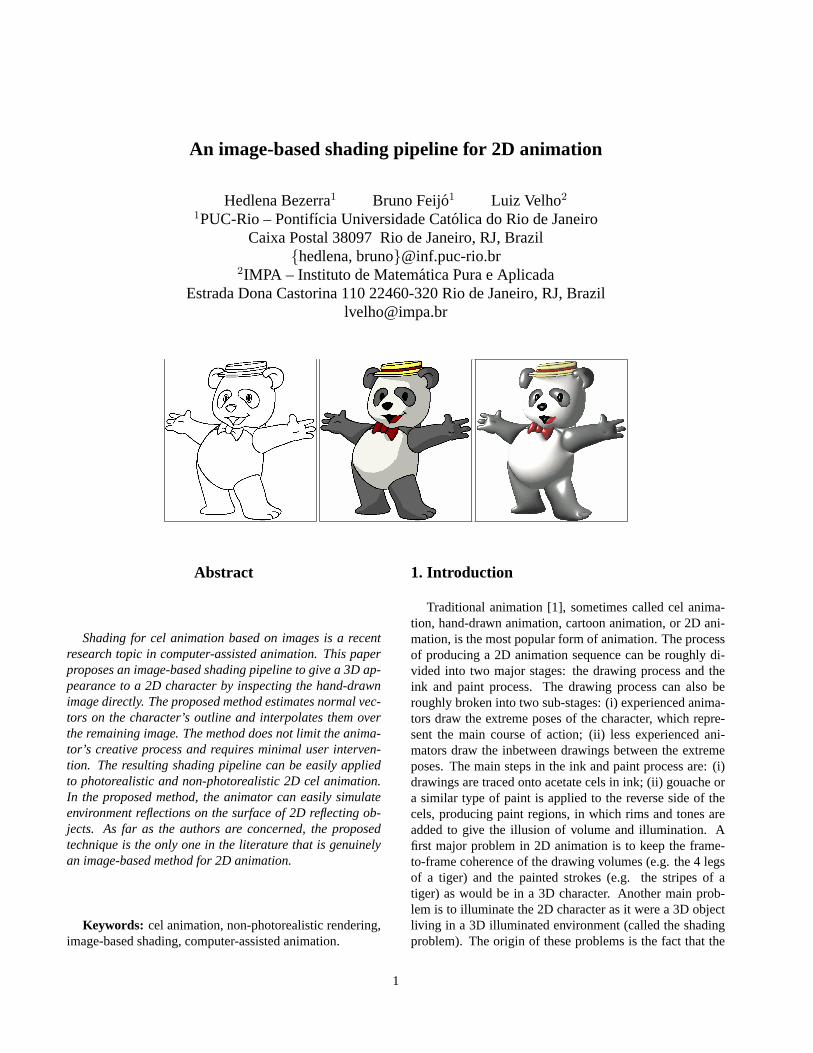
An image-based shading pipeline for 2D animation
Hedlena Bezerra1 Bruno Feijo1 Luiz Velho2
1PUC-Rio – Pontifıcia Universidade Catolica do Rio de JaneiroCaixa Postal 38097 Rio de Janeiro, RJ, Brazil
{hedlena, bruno}@inf.puc-rio.br2IMPA – Instituto de Matematica Pura e Aplicada
Estrada Dona Castorina 110 22460-320 Rio de Janeiro, RJ, [email protected]
Abstract
Shading for cel animation based on images is a recentresearch topic in computer-assisted animation. This paperproposes an image-based shading pipeline to give a 3D ap-pearance to a 2D character by inspecting the hand-drawnimage directly. The proposed method estimates normal vec-tors on the character’s outline and interpolates them overthe remaining image. The method does not limit the anima-tor’s creative process and requires minimal user interven-tion. The resulting shading pipeline can be easily appliedto photorealistic and non-photorealistic 2D cel animation.In the proposed method, the animator can easily simulateenvironment reflections on the surface of 2D reflecting ob-jects. As far as the authors are concerned, the proposedtechnique is the only one in the literature that is genuinelyan image-based method for 2D animation.
Keywords: cel animation, non-photorealistic rendering,image-based shading, computer-assisted animation.
1. Introduction
Traditional animation [1], sometimes called cel anima-tion, hand-drawn animation, cartoon animation, or 2D ani-mation, is the most popular form of animation. The processof producing a 2D animation sequence can be roughly di-vided into two major stages: the drawing process and theink and paint process. The drawing process can also beroughly broken into two sub-stages: (i) experienced anima-tors draw the extreme poses of the character, which repre-sent the main course of action; (ii) less experienced ani-mators draw the inbetween drawings between the extremeposes. The main steps in the ink and paint process are: (i)drawings are traced onto acetate cels in ink; (ii) gouache ora similar type of paint is applied to the reverse side of thecels, producing paint regions, in which rims and tones areadded to give the illusion of volume and illumination. Afirst major problem in 2D animation is to keep the frame-to-frame coherence of the drawing volumes (e.g. the 4 legsof a tiger) and the painted strokes (e.g. the stripes of atiger) as would be in a 3D character. Another main prob-lem is to illuminate the 2D character as it were a 3D objectliving in a 3D illuminated environment (called the shadingproblem). The origin of these problems is the fact that the
1
animator’s drawings and paints are really two-dimensionalprojections of 3D characters as visualized in the animator’smind. These problems become even bigger when computer-assisted animation systems [2, 3] are used. Ed Catmull [4],in 1978, was among the first ones to discuss the frame-to-frame coherence in computer-assisted animation. The shad-ing problem in computer-assisted 2D animation is a muchrecent concern [5, 6, 7, 8, 9], although some related workscould be traced back to the beginning of the 90’s [10]. S.Johnston [8] discusses the shading problem very clearly, in-dicating that the components involved in the illuminationof a point on a surface (position and surface normal) areincomplete in hand-drawn artwork - the surface normal isunknown and the position information lacks depth.
Computer assistance for traditional animation can beconsidered part of the new area of Non-photorealistic Ren-dering - we recommend a visit to the Web page by CraigReynolds [11]. Current research on computer assistance fortraditional animation focuses on two main lines: geometry-based methods and image-based methods. In the first, ge-ometric objects are created in order to support the anima-tion process. The latter uses image-based techniques torender the 2D character without jumping to 3D geometry.The great advantage of the geometry-based methods is thepossibility of supporting both the frame-to-frame coherenceand the shading process. However, these methods cannotcope with more fluid animations, where few strokes wouldchange the implied geometry drastically. On the other hand,image-based methods work directly with the vivid drawingsmade by the artist.
This paper proposes an image-based shading pipeline togive a 3D appearance to a 2D character by inspecting thehand-drawn image directly. The goal is to minimize theuser intervention by extracting information based only onthe 2D image. We show that the character’s outline is theonly information needed to infer a 3D aspect through an il-lumination model. The proposed method estimates normalvectors on the character’s outline and interpolates them overthe remaining image. As far as the authors are concerned,the proposed technique is the only one in the literature thatis genuinely an image-based method. The proposed tech-nique permits animators easily obtain the illusion of light-ing in 2D animation that: does not require 3D input; avoidsscene transformation to vectorial space; and automaticallyenhances depth and position perception.
This paper is organized as follows. Section 2 reviews theprevious works. Section 3 presents a pipeline to process 2Dimages as a preparation for shading effects. Section 4 de-scribes how rendering techniques can be adapted to use 2Dposition and approximate normals to illuminate a drawing.Section 5 describes how to simulate an environment reflec-tion in a geometric 2D object. Section 6 concludes withfinal remarks and a discussion of ongoing work.
2 Previous work
Most of the prior work in this area relies on reconstructedgeometry. Igarashiet al. [6] create a surface from 2D in-formation, providing a gesture-based sketching interface toquickly and easily design freeform models. Correaet al.[5]take a geometry model and deform it to match a hand-drawnfigure. Fiore & Reeth [9] generates approximate 3D modelsin order to help animators keep frame-to-frame coherence.Pretovicet al. [7] presents a scheme for ”inflating” a 3Dfigure based on hand-drawn art to create shadows for celanimation.
The present research was inspired on the seminal workby Scott Johnston [8] that uses image-based techniques. Healso estimates normal vectors and uses sparse interpolationto approximate them over the remaining image to illuminate2D drawings. However, the present work has major con-ceptual and technical differences. The main drawbacks ofthe Johnston’s method are the need of multi-channel imagesand the need of scene transformation to vectorial space. Inour model, we work directly from the 2D image and weavoid transformations to vectorial space completely. This isthe reason why we claim that our method is the only one inthe literature that is genuinely an image-based method.
3. Guessing 3D surfaces from 2D images
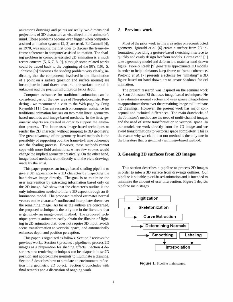
This section describes a pipeline to process 2D imagesin order to infer a 3D surface from drawings outlines. Ourpipeline is suitable to cel-based animation and is intended tominimize the amount of user intervention. Figure 1 depictspipeline main stages.
Figure 1. Pipeline main stages.
2
3.1. Digitization
In the traditional animation process, animators begin bydrawing sequences of animation on a paper with pencils,one picture or ”frame” at a time. The pipeline’s input dataare images made by the traditional cel animation productionprocess. Those images are scanned from cel by a digitalprocess. It is assumed that original drawings contain homo-geneous, non-textured lines drawn onto a white backgroundhaving black outlines. These requirements make the imagescleaning process easier because, in the final step, it will alsohave black line drawings in a white background.
After the scanning process, each cel has registrationholes. Those small holes allow the cel to be placed onpegs to ensure each cel aligns with the one before it. Ifthe cells are not aligned in such a manner, the animation,when played at full speed, will look ”jittery.”
3.2. Skeletonization
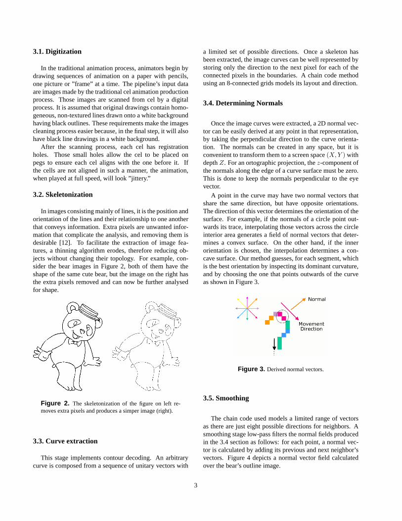
In images consisting mainly of lines, it is the position andorientation of the lines and their relationship to one anotherthat conveys information. Extra pixels are unwanted infor-mation that complicate the analysis, and removing them isdesirable [12]. To facilitate the extraction of image fea-tures, a thinning algorithm erodes, therefore reducing ob-jects without changing their topology. For example, con-sider the bear images in Figure 2, both of them have theshape of the same cute bear, but the image on the right hasthe extra pixels removed and can now be further analysedfor shape.
Figure 2. The skeletonization of the figure on left re-moves extra pixels and produces a simper image (right).
3.3. Curve extraction
This stage implements contour decoding. An arbitrarycurve is composed from a sequence of unitary vectors with
a limited set of possible directions. Once a skeleton hasbeen extracted, the image curves can be well represented bystoring only the direction to the next pixel for each of theconnected pixels in the boundaries. A chain code methodusing an 8-connected grids models its layout and direction.
3.4. Determining Normals
Once the image curves were extracted, a 2D normal vec-tor can be easily derived at any point in that representation,by taking the perpendicular direction to the curve orienta-tion. The normals can be created in any space, but it isconvenient to transform them to a screen space(X, Y ) withdepthZ. For an ortographic projection, thez-component ofthe normals along the edge of a curve surface must be zero.This is done to keep the normals perpendicular to the eyevector.
A point in the curve may have two normal vectors thatshare the same direction, but have opposite orientations.The direction of this vector determines the orientation of thesurface. For example, if the normals of a circle point out-wards its trace, interpolating those vectors across the circleinterior area generates a field of normal vectors that deter-mines a convex surface. On the other hand, if the innerorientation is chosen, the interpolation determines a con-cave surface. Our method guesses, for each segment, whichis the best orientation by inspecting its dominant curvature,and by choosing the one that points outwards of the curveas shown in Figure 3.
Figure 3. Derived normal vectors.
3.5. Smoothing
The chain code used models a limited range of vectorsas there are just eight possible directions for neighbors. Asmoothing stage low-pass filters the normal fields producedin the 3.4 section as follows: for each point, a normal vec-tor is calculated by adding its previous and next neighbor’svectors. Figure 4 depicts a normal vector field calculatedover the bear’s outline image.
3
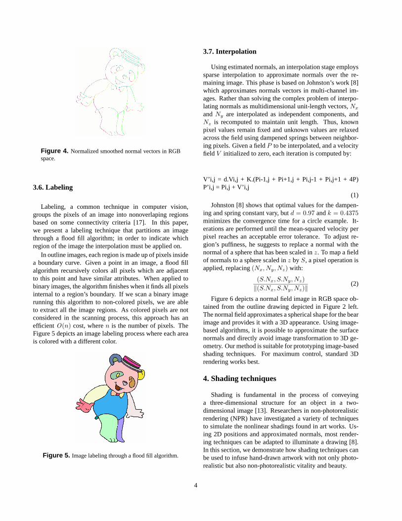
Figure 4. Normalized smoothed normal vectors in RGBspace.
3.6. Labeling
Labeling, a common technique in computer vision,groups the pixels of an image into nonoverlaping regionsbased on some connectivity criteria [17]. In this paper,we present a labeling technique that partitions an imagethrough a flood fill algorithm; in order to indicate whichregion of the image the interpolation must be applied on.
In outline images, each region is made up of pixels insidea boundary curve. Given a point in an image, a flood fillalgorithm recursively colors all pixels which are adjacentto this point and have similar attributes. When applied tobinary images, the algorithm finishes when it finds all pixelsinternal to a region’s boundary. If we scan a binary imagerunning this algorithm to non-colored pixels, we are ableto extract all the image regions. As colored pixels are notconsidered in the scanning process, this approach has anefficientO(n) cost, wheren is the number of pixels. TheFigure 5 depicts an image labeling process where each areais colored with a different color.
Figure 5. Image labeling through a flood fill algorithm.
3.7. Interpolation
Using estimated normals, an interpolation stage employssparse interpolation to approximate normals over the re-maining image. This phase is based on Johnston’s work [8]which approximates normals vectors in multi-channel im-ages. Rather than solving the complex problem of interpo-lating normals as multidimensional unit-length vectors,Nx
and Ny are interpolated as independent components, andNz is recomputed to maintain unit length. Thus, knownpixel values remain fixed and unknown values are relaxedacross the field using dampened springs between neighbor-ing pixels. Given a fieldP to be interpolated, and a velocityfield V initialized to zero, each iteration is computed by:
V’i,j = d.Vi,j + K.(Pi-1,j + Pi+1,j + Pi,j-1 + Pi,j+1 + 4P)P’i,j = Pi,j + V’i,j
(1)
Johnston [8] shows that optimal values for the dampen-ing and spring constant vary, butd = 0.97 andk = 0.4375minimizes the convergence time for a circle example. It-erations are performed until the mean-squared velocity perpixel reaches an acceptable error tolerance. To adjust re-gion’s puffiness, he suggests to replace a normal with thenormal of a sphere that has been scaled inz. To map a fieldof normals to a sphere scaled inz by S, a pixel operation isapplied, replacing(Nx, Ny, Nz) with:
(S.Nx, S.Ny, Nz)‖(S.Nx, S.Ny, Nz)‖
(2)
Figure 6 depicts a normal field image in RGB space ob-tained from the outline drawing depicted in Figure 2 left.The normal field approximates a spherical shape for the bearimage and provides it with a 3D appearance. Using image-based algorithms, it is possible to approximate the surfacenormals and directly avoid image transformation to 3D ge-ometry. Our method is suitable for prototyping image-basedshading techniques. For maximum control, standard 3Drendering works best.
4. Shading techniques
Shading is fundamental in the process of conveyinga three-dimensional structure for an object in a two-dimensional image [13]. Researchers in non-photorealisticrendering (NPR) have investigated a variety of techniquesto simulate the nonlinear shadings found in art works. Us-ing 2D positions and approximated normals, most render-ing techniques can be adapted to illuminate a drawing [8].In this section, we demonstrate how shading techniques canbe used to infuse hand-drawn artwork with not only photo-realistic but also non-photorealistic vitality and beauty.
4
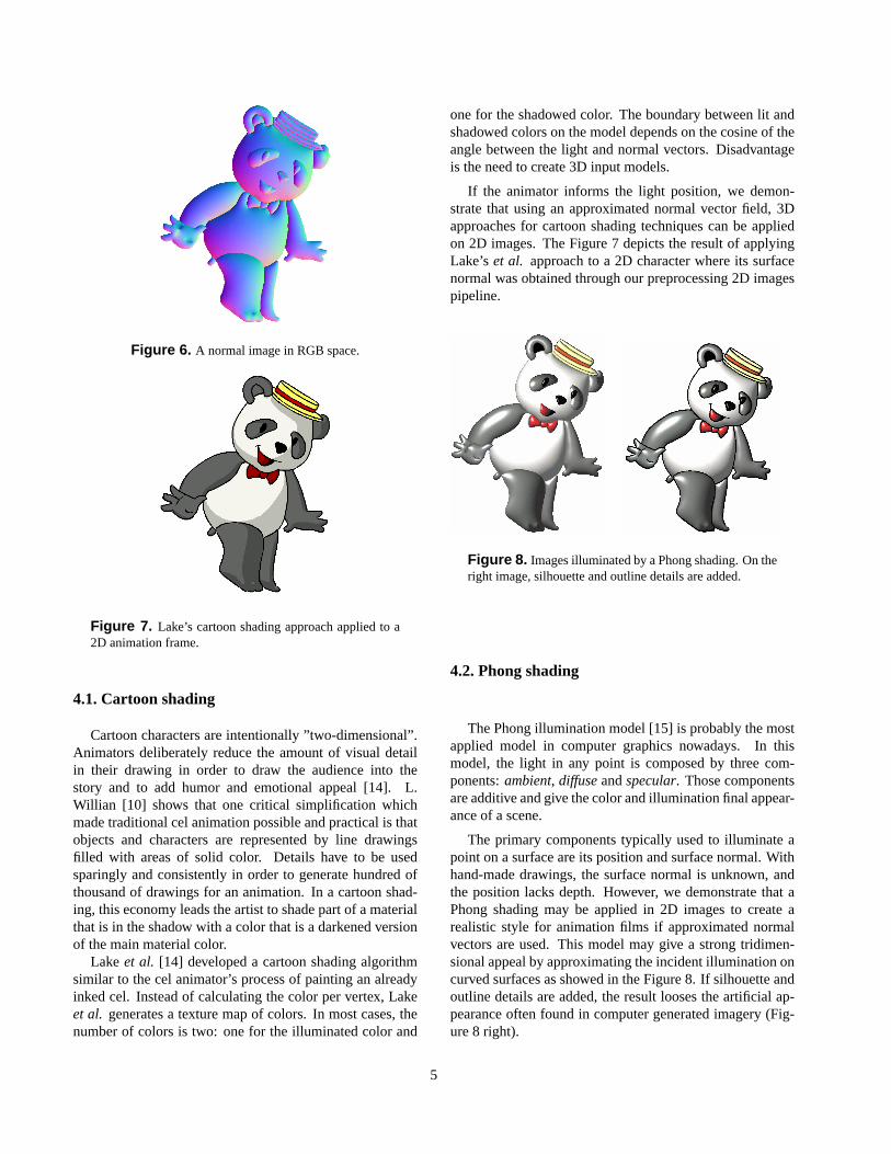
Figure 6. A normal image in RGB space.
Figure 7. Lake’s cartoon shading approach applied to a2D animation frame.
4.1. Cartoon shading
Cartoon characters are intentionally ”two-dimensional”.Animators deliberately reduce the amount of visual detailin their drawing in order to draw the audience into thestory and to add humor and emotional appeal [14]. L.Willian [10] shows that one critical simplification whichmade traditional cel animation possible and practical is thatobjects and characters are represented by line drawingsfilled with areas of solid color. Details have to be usedsparingly and consistently in order to generate hundred ofthousand of drawings for an animation. In a cartoon shad-ing, this economy leads the artist to shade part of a materialthat is in the shadow with a color that is a darkened versionof the main material color.
Lake et al. [14] developed a cartoon shading algorithmsimilar to the cel animator’s process of painting an alreadyinked cel. Instead of calculating the color per vertex, Lakeet al. generates a texture map of colors. In most cases, thenumber of colors is two: one for the illuminated color and
one for the shadowed color. The boundary between lit andshadowed colors on the model depends on the cosine of theangle between the light and normal vectors. Disadvantageis the need to create 3D input models.
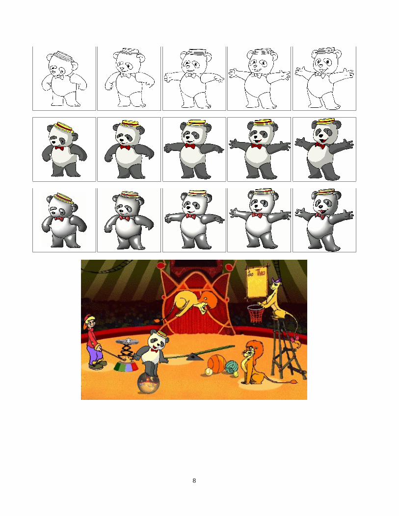
If the animator informs the light position, we demon-strate that using an approximated normal vector field, 3Dapproaches for cartoon shading techniques can be appliedon 2D images. The Figure 7 depicts the result of applyingLake’s et al. approach to a 2D character where its surfacenormal was obtained through our preprocessing 2D imagespipeline.
Figure 8. Images illuminated by a Phong shading. On theright image, silhouette and outline details are added.
4.2. Phong shading
The Phong illumination model [15] is probably the mostapplied model in computer graphics nowadays. In thismodel, the light in any point is composed by three com-ponents:ambient, diffuseandspecular. Those componentsare additive and give the color and illumination final appear-ance of a scene.
The primary components typically used to illuminate apoint on a surface are its position and surface normal. Withhand-made drawings, the surface normal is unknown, andthe position lacks depth. However, we demonstrate that aPhong shading may be applied in 2D images to create arealistic style for animation films if approximated normalvectors are used. This model may give a strong tridimen-sional appeal by approximating the incident illumination oncurved surfaces as showed in the Figure 8. If silhouette andoutline details are added, the result looses the artificial ap-pearance often found in computer generated imagery (Fig-ure 8 right).
5
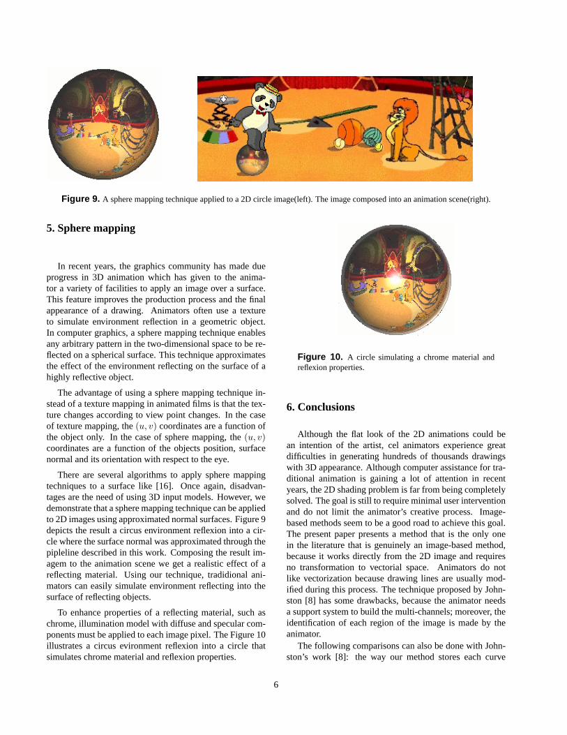
Figure 9. A sphere mapping technique applied to a 2D circle image(left). The image composed into an animation scene(right).
5. Sphere mapping
In recent years, the graphics community has made dueprogress in 3D animation which has given to the anima-tor a variety of facilities to apply an image over a surface.This feature improves the production process and the finalappearance of a drawing. Animators often use a textureto simulate environment reflection in a geometric object.In computer graphics, a sphere mapping technique enablesany arbitrary pattern in the two-dimensional space to be re-flected on a spherical surface. This technique approximatesthe effect of the environment reflecting on the surface of ahighly reflective object.
The advantage of using a sphere mapping technique in-stead of a texture mapping in animated films is that the tex-ture changes according to view point changes. In the caseof texture mapping, the(u, v) coordinates are a function ofthe object only. In the case of sphere mapping, the(u, v)coordinates are a function of the objects position, surfacenormal and its orientation with respect to the eye.
There are several algorithms to apply sphere mappingtechniques to a surface like [16]. Once again, disadvan-tages are the need of using 3D input models. However, wedemonstrate that a sphere mapping technique can be appliedto 2D images using approximated normal surfaces. Figure 9depicts the result a circus environment reflexion into a cir-cle where the surface normal was approximated through thepipleline described in this work. Composing the result im-agem to the animation scene we get a realistic effect of areflecting material. Using our technique, tradidional ani-mators can easily simulate environment reflecting into thesurface of reflecting objects.
To enhance properties of a reflecting material, such aschrome, illumination model with diffuse and specular com-ponents must be applied to each image pixel. The Figure 10illustrates a circus evironment reflexion into a circle thatsimulates chrome material and reflexion properties.
Figure 10. A circle simulating a chrome material andreflexion properties.
6. Conclusions
Although the flat look of the 2D animations could bean intention of the artist, cel animators experience greatdifficulties in generating hundreds of thousands drawingswith 3D appearance. Although computer assistance for tra-ditional animation is gaining a lot of attention in recentyears, the 2D shading problem is far from being completelysolved. The goal is still to require minimal user interventionand do not limit the animator’s creative process. Image-based methods seem to be a good road to achieve this goal.The present paper presents a method that is the only onein the literature that is genuinely an image-based method,because it works directly from the 2D image and requiresno transformation to vectorial space. Animators do notlike vectorization because drawing lines are usually mod-ified during this process. The technique proposed by John-ston [8] has some drawbacks, because the animator needsa support system to build the multi-channels; moreover, theidentification of each region of the image is made by theanimator.
The following comparisons can also be done with John-ston’s work [8]: the way our method stores each curve
6
(chain code) makes easy the task of finding normal vec-tors at each point (there is no need for using gradients asin [8]); the animator needs only to select the curve and setthe orientation parameter in order to define the orientationof the normal vectors (there is no need for ”light over dark”lines along each curve as in [8]); the segmentation process(labeling) is automatic, apart from the selection of the finalcolor of each region (this process is not automatic in [8]).There is also a difference towards the objectives of the sys-tem: our method is for traditional cartoon animation, whileJohnston [8] envisages the blending of 2D animation andlive action as in ”Who Framed Roger Rabbit” (1998) [18].
Further work will be carried out in building a frameworkto visual creation and edition of computer assisted anima-tions. Through this framework, the animator will work ininteractive high level programming environment which pro-vides a fast adapted concept of: (i) shade engines (e.g. Per-lin’s Pixel Stream Editor [19]), (ii) shading languages (e.g.Cook’s shade Trees [20] and Pixar Renderman [21]), (iii)real-time previews using normal look-up tables, (iv) real-time shadow effects by changing light position, (v) newstyles application by learning analogies (e.g. Aaron Hertz-mannet al. [22] Image Analogies) and (vi) creation of astyles library.
Acknowledgments. The authors thank Cesar Coelho forall lovely bear outlines and his support as a renowned tradi-tional animator. We also would like to thank Ives MacedoJunior and Marcelo Vieira for many helpful discussionsand comments regarding the present work. This work wasdeveloped at ICAD/VisionLab (PUC-Rio) - sponsored byCNPq and FINEP - and VISGRAF (IMPA) - sponsoredby CNPq, FAPERJ, FINEP, and IBM Brasil. The first au-thor is partially supported by scholarships from PUC-Rioand CAPES. The second author’s research work is underresearch contracts CNPq Grant PQ No. 305982/2003-6,SEPIN-CNPQ-FINEP No. 01.02.0230.00 (Ref. 2425/02)and FINEP No. 01.04.0945.00 (Ref. 3110/04).
References
[1] P. Blair. Cartoon Animation. Walter Foster Pub. Inc.,1994.
[2] J. D. Fekete, E. Bizouarn, E. Cournarie, T. Galas andF. Taillefer. TicTacToon: A paperless system for pro-fessional 2D animation. In Proc. of SIGGRAPH’95, p79–90, 1995.
[3] H. Griffin. The Animator’s Guide to 2D Computer An-imation. Focal Press, 2001.
[4] E. Catmull. The problems of computer-assisted anima-tion. In Proc. of SIGGRAPH’78, p. 348–303, 1978.
[5] W. T. Correa, R. J. Jensen, C. E. Thayer and A. Finkel-stein. Texture Mapping for Cel Animation. In Proc. ofSIGGRAPH’98, p. 430–446, 1998.
[6] T. Igarashi, S. Matsuoka and H. Tanaka. Teddy: asketching interface for 3D freeform design. In Proc. ofSIGGRAPH’99, p 409–416, 1999.
[7] L. Petrovic, B. Fujito, L. Williams and A. Finkelstein.Shadows for cel animation. In Proc. of SIGGRAPH’00,p. 511–516, 2000.
[8] S. F. Johnston. Lumo: Illumination for cel animation.In Proc. of NPAR 2002, p. 45–52 and p. 156, 2002.
[9] F. Di Fiore and F. Van Reeth. Employing Approximate3D Models to Enrich Traditional Computer AssistedAnimation. In Proc. of Computer Animation, p. 183–190, 2002.
[10] L. Williams. Shading in two dimensions. In Proc. ofGraphics Interface, p. 143–151, 1991.
[11] C. Reynolds. Stylized Depiction in ComputerGraphics – Non-Photorealistic, Painterly and ’TonnRendering, www.red3d.com/cwr/npr [accessed in12/May/2005].
[12] J. R. Parker. Pratical Computer Vision using C. JohnWiley and Sons Inc., 1994.
[13] Bruce Gooch and Amy Gooch. Non-PhotorealisticAnimation Rendering. A K Peters Ltd., 2001.
[14] A. Lake, C. Marshall, M. Harris and M. Blackstein.Stylized Rendering techniques for scalable real-time3D animation. In Proc. of NPAR 2000, p. 13–20, 2000.
[15] B. Phong. Illumination for computer-generated pic-tures. Communications of the ACM, V.18 #3 p. 311–317, 1975.
[16] L. Velho and J. Gomes. Sistemas Graficos 3D. Insti-tuto de Matematica Pura e Aplicada – IMPA, 2001.
[17] E. Davies. Machine Vision: Theory, Algorithms andPracticalities. Academic Press, 1990.
[18] C. Solomon. Enchanted Drawings: the History of An-imation. Knopf, 1989.
[19] K. Perlin. Image analogies. In Proc. of SIG-GRAPH’85, pp 287–296, 1985.
[20] Robert L. Cook. Illumination for computer-generatedpictures. In Proc. of SIGGRAPH’84, p. 223–231, 1984.
[21] Pixar Animation Studios. Pixar’s RenderManProducts, https://renderman.pixar.com/ [accessed in15/May/2005]
[22] A. Hertzmann, C. E. Jacobs, N. Oliver, B. Curlessand D. H. Salesin. Image analogies. In Proc. of SIG-GRAPH’01, p. 327–340, 2001.
7
8